EP3967867A1 - Fuel system for an internal combustion engine - Google Patents
Fuel system for an internal combustion engine Download PDFInfo
- Publication number
- EP3967867A1 EP3967867A1 EP21196519.9A EP21196519A EP3967867A1 EP 3967867 A1 EP3967867 A1 EP 3967867A1 EP 21196519 A EP21196519 A EP 21196519A EP 3967867 A1 EP3967867 A1 EP 3967867A1
- Authority
- EP
- European Patent Office
- Prior art keywords
- fuel
- pressure
- low
- pressure fuel
- delivery unit
- Prior art date
- Legal status (The legal status is an assumption and is not a legal conclusion. Google has not performed a legal analysis and makes no representation as to the accuracy of the status listed.)
- Pending
Links
- 239000000446 fuel Substances 0.000 title claims abstract description 298
- 238000002485 combustion reaction Methods 0.000 title claims description 40
- 230000010349 pulsation Effects 0.000 claims abstract description 46
- 239000012530 fluid Substances 0.000 claims abstract description 8
- 238000005086 pumping Methods 0.000 description 24
- 239000002828 fuel tank Substances 0.000 description 11
- 230000008901 benefit Effects 0.000 description 5
- 238000001816 cooling Methods 0.000 description 3
- 238000002347 injection Methods 0.000 description 3
- 239000007924 injection Substances 0.000 description 3
- 238000005461 lubrication Methods 0.000 description 3
- 230000002411 adverse Effects 0.000 description 2
- 230000000694 effects Effects 0.000 description 2
- 238000005457 optimization Methods 0.000 description 2
- 230000003466 anti-cipated effect Effects 0.000 description 1
- 238000005094 computer simulation Methods 0.000 description 1
- 230000001351 cycling effect Effects 0.000 description 1
- 239000003502 gasoline Substances 0.000 description 1
- 230000000116 mitigating effect Effects 0.000 description 1
- 238000011144 upstream manufacturing Methods 0.000 description 1
Images


Classifications
-
- F—MECHANICAL ENGINEERING; LIGHTING; HEATING; WEAPONS; BLASTING
- F02—COMBUSTION ENGINES; HOT-GAS OR COMBUSTION-PRODUCT ENGINE PLANTS
- F02M—SUPPLYING COMBUSTION ENGINES IN GENERAL WITH COMBUSTIBLE MIXTURES OR CONSTITUENTS THEREOF
- F02M63/00—Other fuel-injection apparatus having pertinent characteristics not provided for in groups F02M39/00 - F02M57/00 or F02M67/00; Details, component parts, or accessories of fuel-injection apparatus, not provided for in, or of interest apart from, the apparatus of groups F02M39/00 - F02M61/00 or F02M67/00; Combination of fuel pump with other devices, e.g. lubricating oil pump
- F02M63/02—Fuel-injection apparatus having several injectors fed by a common pumping element, or having several pumping elements feeding a common injector; Fuel-injection apparatus having provisions for cutting-out pumps, pumping elements, or injectors; Fuel-injection apparatus having provisions for variably interconnecting pumping elements and injectors alternatively
- F02M63/0225—Fuel-injection apparatus having a common rail feeding several injectors ; Means for varying pressure in common rails; Pumps feeding common rails
- F02M63/0275—Arrangement of common rails
- F02M63/0285—Arrangement of common rails having more than one common rail
- F02M63/029—Arrangement of common rails having more than one common rail per cylinder bank, e.g. storing different fuels or fuels at different pressure levels per cylinder bank
-
- F—MECHANICAL ENGINEERING; LIGHTING; HEATING; WEAPONS; BLASTING
- F02—COMBUSTION ENGINES; HOT-GAS OR COMBUSTION-PRODUCT ENGINE PLANTS
- F02M—SUPPLYING COMBUSTION ENGINES IN GENERAL WITH COMBUSTIBLE MIXTURES OR CONSTITUENTS THEREOF
- F02M59/00—Pumps specially adapted for fuel-injection and not provided for in groups F02M39/00 -F02M57/00, e.g. rotary cylinder-block type of pumps
- F02M59/20—Varying fuel delivery in quantity or timing
- F02M59/205—Quantity of fuel admitted to pumping elements being metered by an auxiliary metering device
-
- F—MECHANICAL ENGINEERING; LIGHTING; HEATING; WEAPONS; BLASTING
- F02—COMBUSTION ENGINES; HOT-GAS OR COMBUSTION-PRODUCT ENGINE PLANTS
- F02M—SUPPLYING COMBUSTION ENGINES IN GENERAL WITH COMBUSTIBLE MIXTURES OR CONSTITUENTS THEREOF
- F02M37/00—Apparatus or systems for feeding liquid fuel from storage containers to carburettors or fuel-injection apparatus; Arrangements for purifying liquid fuel specially adapted for, or arranged on, internal-combustion engines
- F02M37/0011—Constructional details; Manufacturing or assembly of elements of fuel systems; Materials therefor
- F02M37/0023—Valves in the fuel supply and return system
- F02M37/0029—Pressure regulator in the low pressure fuel system
-
- F—MECHANICAL ENGINEERING; LIGHTING; HEATING; WEAPONS; BLASTING
- F02—COMBUSTION ENGINES; HOT-GAS OR COMBUSTION-PRODUCT ENGINE PLANTS
- F02M—SUPPLYING COMBUSTION ENGINES IN GENERAL WITH COMBUSTIBLE MIXTURES OR CONSTITUENTS THEREOF
- F02M37/00—Apparatus or systems for feeding liquid fuel from storage containers to carburettors or fuel-injection apparatus; Arrangements for purifying liquid fuel specially adapted for, or arranged on, internal-combustion engines
- F02M37/0011—Constructional details; Manufacturing or assembly of elements of fuel systems; Materials therefor
- F02M37/0041—Means for damping pressure pulsations
-
- F—MECHANICAL ENGINEERING; LIGHTING; HEATING; WEAPONS; BLASTING
- F02—COMBUSTION ENGINES; HOT-GAS OR COMBUSTION-PRODUCT ENGINE PLANTS
- F02M—SUPPLYING COMBUSTION ENGINES IN GENERAL WITH COMBUSTIBLE MIXTURES OR CONSTITUENTS THEREOF
- F02M37/00—Apparatus or systems for feeding liquid fuel from storage containers to carburettors or fuel-injection apparatus; Arrangements for purifying liquid fuel specially adapted for, or arranged on, internal-combustion engines
- F02M37/0047—Layout or arrangement of systems for feeding fuel
-
- F—MECHANICAL ENGINEERING; LIGHTING; HEATING; WEAPONS; BLASTING
- F02—COMBUSTION ENGINES; HOT-GAS OR COMBUSTION-PRODUCT ENGINE PLANTS
- F02M—SUPPLYING COMBUSTION ENGINES IN GENERAL WITH COMBUSTIBLE MIXTURES OR CONSTITUENTS THEREOF
- F02M55/00—Fuel-injection apparatus characterised by their fuel conduits or their venting means; Arrangements of conduits between fuel tank and pump F02M37/00
- F02M55/02—Conduits between injection pumps and injectors, e.g. conduits between pump and common-rail or conduits between common-rail and injectors
-
- F—MECHANICAL ENGINEERING; LIGHTING; HEATING; WEAPONS; BLASTING
- F02—COMBUSTION ENGINES; HOT-GAS OR COMBUSTION-PRODUCT ENGINE PLANTS
- F02M—SUPPLYING COMBUSTION ENGINES IN GENERAL WITH COMBUSTIBLE MIXTURES OR CONSTITUENTS THEREOF
- F02M55/00—Fuel-injection apparatus characterised by their fuel conduits or their venting means; Arrangements of conduits between fuel tank and pump F02M37/00
- F02M55/02—Conduits between injection pumps and injectors, e.g. conduits between pump and common-rail or conduits between common-rail and injectors
- F02M55/025—Common rails
-
- F—MECHANICAL ENGINEERING; LIGHTING; HEATING; WEAPONS; BLASTING
- F02—COMBUSTION ENGINES; HOT-GAS OR COMBUSTION-PRODUCT ENGINE PLANTS
- F02M—SUPPLYING COMBUSTION ENGINES IN GENERAL WITH COMBUSTIBLE MIXTURES OR CONSTITUENTS THEREOF
- F02M55/00—Fuel-injection apparatus characterised by their fuel conduits or their venting means; Arrangements of conduits between fuel tank and pump F02M37/00
- F02M55/04—Means for damping vibrations or pressure fluctuations in injection pump inlets or outlets
-
- F—MECHANICAL ENGINEERING; LIGHTING; HEATING; WEAPONS; BLASTING
- F02—COMBUSTION ENGINES; HOT-GAS OR COMBUSTION-PRODUCT ENGINE PLANTS
- F02M—SUPPLYING COMBUSTION ENGINES IN GENERAL WITH COMBUSTIBLE MIXTURES OR CONSTITUENTS THEREOF
- F02M2200/00—Details of fuel-injection apparatus, not otherwise provided for
- F02M2200/31—Fuel-injection apparatus having hydraulic pressure fluctuations damping elements
- F02M2200/315—Fuel-injection apparatus having hydraulic pressure fluctuations damping elements for damping fuel pressure fluctuations
Definitions
- the present disclosure relates to a fuel system for an internal combustion engine; more particularly to a fuel system which includes a portion for delivering fuel directly to the combustion chamber of the internal combustion engine at a relatively high pressure and a portion for delivering fuel upstream of the combustion chamber at a relatively low pressure; and still even more particularly to a fuel system where a high-pressure fuel delivery unit is cooled and lubricated even when little or no fuel is delivered directly to the combustion chamber.
- the means for reducing fuel pressure pulsations may include a chamber which provides an enlarged volume.
- a wall of said chamber is flexible in response to said fuel pressure pulsations.
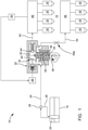
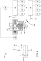
- FIGS. 1-4 are schematic views of fuel systems in accordance with the present disclosure.
- Fuel system 10 generally includes a fuel tank 14 which holds a volume of fuel to be supplied to internal combustion engine 12 for operation thereof; a plurality of high-pressure fuel injectors 16 which inject fuel directly into respective combustion chambers (not shown) of internal combustion engine 12; a plurality of low-pressure fuel injectors 18 which inject fuel into an air intake manifold or other combustion air passage (not shown) of internal combustion engine 12 where the fuel mixes with air and is subsequently passed to the combustion chambers through respective intake valves (not shown); a low-pressure fuel delivery unit 20; and a high-pressure fuel delivery unit 22 where the low-pressure fuel delivery unit 20 draws fuel from fuel tank 14 and elevates the pressure of the fuel for delivery to high-pressure fuel delivery unit 22 and to low-pressure fuel injectors 18 and where the high-pressure fuel delivery unit 22 further elevates the pressure of the fuel for delivery to high-pressure fuel injectors 16.
- a fuel tank 14 which holds a volume of fuel to be supplied to internal combustion engine 12 for operation thereof
- high-pressure fuel injectors 16 or by low-pressure fuel injectors 18. It is also contemplated that fuel may be delivered to the combustion chambers by both high-pressure fuel injectors 16 and by low-pressure fuel injectors 18 concurrently. While four high-pressure fuel injectors 16 and four low-pressure fuel injectors 18 have been illustrated, it should be understood that a lesser or greater number of each of high-pressure fuel injectors 16 and low-pressure fuel injectors 18 may be provided. The various elements of fuel system 10 will be described in greater detail in the paragraphs that follow.
- High-pressure fuel delivery unit 22 includes a low-pressure region 30 and a high-pressure region 32.
- High-pressure fuel delivery unit 22 may be a plunger pump which is mechanically driven by internal combustion engine 12 such that low-pressure region 30 includes a pumping plunger 34 which is reciprocated within a plunger bore 36 by a rotating camshaft 38 of internal combustion engine 12.
- High-pressure region 32 includes an inlet valve 40, a pumping chamber 42, and an outlet valve 44.
- Low-pressure region 30 includes all of the portions of high-pressure fuel delivery unit 22 that are in fluid communication with low-pressure fuel supply passage 24 when inlet valve 40 is closed.
- the fuel within pumping chamber 42 is pressurized by reciprocation of pumping plunger 34, and when the pressure within pumping chamber 42 is sufficiently high, outlet valve 44 is caused to open. Fuel that exits high-pressure fuel delivery unit 22 through outlet valve 44 is communicated, via a high-pressure fuel passage 45, to a high-pressure fuel rail 46 with which each of high-pressure fuel injectors 16 are in fluid communication.
- Inlet valve 40 may be, by way of non-limiting example only, a solenoid operated valve which is controlled by a controller 48. Controller 48 may receive input from a pressure sensor 50 which supplies a signal indicative of the pressure of the fuel being supplied to high-pressure fuel injectors 16.
- pressure sensor 50 is shown arranged to read the fuel pressure within high-pressure fuel rail 46, it should be understood that pressure sensor 50 may be positioned at other locations that are indicative of the pressure of the fuel being supplied to high-pressure fuel injectors 16. Controller 48 sends signals to inlet valve 40 to open and close inlet valve 40 as necessary to achieve a desired fuel pressure at pressure sensor 50 as may be determined by current and anticipated engine operating demands. When inlet valve 40 is opened while pumping plunger 34 is moving to increase the volume of pumping chamber 42, fuel from low-pressure fuel supply passage 24 is allowed to flow into pumping chamber 42.
- a low-pressure fuel injector supply passage 54 is connected at one end directly to high-pressure fuel delivery unit 22, more particularly to low-pressure region 30 and even more particularly to the portion of low-pressure region 30 which surrounds pumping plunger 34, and is connected at its other end directly to a low-pressure fuel rail 56 with which each of low-pressure fuel injectors 18 are in fluid communication.
- Low-pressure fuel injector supply passage 54 provides fluid communication from high-pressure fuel delivery unit 22 to low-pressure fuel rail 56. However, it is important to note that low-pressure fuel injector supply passage 54 receives fuel from high-pressure fuel delivery unit 22 without the fuel passing through pumping chamber 42.
- charging is understood to be filling pumping chamber 42 with fuel when pumping plunger 34 is moving to expand pumping chamber 42 and spilling is flowing fuel from pumping chamber 42 back to low-pressure fuel supply passage 24 and/or low-pressure region 30 when pumping plunger 34 is moving to decrease pumping chamber 42 in volume while inlet valve 40 is open (done in order to provide a desired output of fuel from high-pressure fuel delivery unit 22).
- the means for reducing fuel pressure pulsations is indicated by reference number 58b which takes the form of a check valve which allows fuel flow from high-pressure fuel delivery unit 22 to low-pressure fuel rail 56, but prohibits fuel flow in the opposite direction. Similar to the orifice or restriction, the check valve provides a restriction or impedance to flow which inhibits propagation of the pressure pulsation within low-pressure fuel injector supply passage 54.
- the means for reducing fuel pressure pulsations is indicated by reference number 58c which takes the form of a chamber or accumulator which includes an area of enlarged cross-sectional area within low-pressure fuel injector supply passage 54.
- the chamber or accumulator provides an enlarged volume within which pressure pulsations may naturally reflect and decrease in magnitude.
- a pulsation damper 60 may be located within the chamber or accumulator such that the pulsation damper 60 is flexible and resilient in nature in order to adsorb the pressure pulsations.
- Pulsation damper 60 may take the form of an imperforate hollow and flexible shell which is pressurized with a gas.
- the pressure pulsations cause the shell of pulsation damper 60 to flex inward and the pressurized gas returns the shell to its original shape, thereby mitigating the pressure pulsations.
- An example of a suitable pulsation damper is described in United States Patent No. 8,727,752 to Lucas , the disclosure of which is hereby incorporated by reference in its entirety.
- a wall which defines the chamber or accumulator is flexible in response to the fuel pressure pulsations in order to mitigate the fuel pressure pulsations by flexing outward, either with or without the presence of pulsation damper 60 therewithin.
- the means for reducing fuel pressure pulsations 58d includes two or more of the restriction or orifice of FIG. 1 , the check valve of FIG. 2 , and the chamber or accumulator of FIG. 3 . While all three devices 58d have been illustrated, it should be understood that one may be omitted. It should also be understood that duplicates of some of the devices may be additionally included. Furthermore, while the devices 58d have been illustrated as being arranged in series (in a line), it should be understood that a parallel arrangement or a combination of series and parallel may be utilized. Optimization for specific fuel system applications can be made by choosing the most effective orifice or restriction size, check valve flow rate and opening pressure, and chamber or accumulator volume and flexing characteristics. This optimization may be achieved, by way of non-limiting example only, through empirical testing or computer simulation.
- low-pressure fuel delivery unit 20 draws fuel from fuel tank 14 and passes the fuel to high-pressure fuel delivery unit 22 through low-pressure fuel supply passage 24.
- the fuel supplied to high-pressure fuel delivery unit 22 passes through low-pressure region 30 and exits high-pressure fuel delivery unit 22 through low-pressure fuel injector supply passage 54.
- the fuel then passes to low-pressure fuel rail 56 where it is distributed to low-pressure fuel injectors 18 and subsequently.
- high-pressure fuel delivery unit 22 is lubricated and cooled even when only low-pressure fuel injectors 18 are used to supply fuel to the combustion chambers of internal combustion engine 12 or when low-pressure fuel injectors 18 are used to supply fuel to the combustion chambers concurrently with high-pressure fuel injectors 16 providing a low rate of fuel to the combustion chambers of internal combustion engine 12.
Landscapes
- Engineering & Computer Science (AREA)
- Chemical & Material Sciences (AREA)
- Combustion & Propulsion (AREA)
- Mechanical Engineering (AREA)
- General Engineering & Computer Science (AREA)
- Fuel-Injection Apparatus (AREA)
Abstract
Description
- The present disclosure relates to a fuel system for an internal combustion engine; more particularly to a fuel system which includes a portion for delivering fuel directly to the combustion chamber of the internal combustion engine at a relatively high pressure and a portion for delivering fuel upstream of the combustion chamber at a relatively low pressure; and still even more particularly to a fuel system where a high-pressure fuel delivery unit is cooled and lubricated even when little or no fuel is delivered directly to the combustion chamber.
- Fuel systems for modern internal combustion engines typically employ either 1) port fuel injection (PFI) where fuel is injected into an air intake manifold or other combustion air passage of the internal combustion engine at relatively low pressure (typically below about 500 kPa) and subsequently passed to the combustion chamber of the internal combustion engine or 2) gasoline direct injection (GDi) where fuel is injected directly into the combustion chamber of the internal combustion engine at relatively high pressure (typically above about 14 MPa). However, some fuel systems have been developed which employ both PFI and GDi in order to take advantage of operating modes where PFI provides operational benefits and in order to take advantage of operating modes where GDi provides operational benefits. Consequently, only the PFI may be utilized under some operating conditions while only GDi may be utilized under other operating conditions.
- One example of a fuel system which employs both PFI and GDi is described in
United States Patent number 7,263,973 to Akita et al. ; however, a disadvantage of the system of Akita et al. is that when only the PFI system is used, the high-pressure fuel pump used to pressurize the fuel in the GDi system continues to be cycled by a camshaft of the internal combustion engine. This cycling, along with the close proximity of the high-pressure fuel pump to the internal combustion engine, causes fuel in the high-pressure fuel pump to elevate in temperature and potentially create vapor in the GDi system which is undesirable for the high-pressure fuel pump and which may hinder fueling when the GDi system is used. -
United States Patent number 8,973,556 to Hoefner et al. describes another fuel system which employs both PFI and GDi. Hoefner et al. provides an arrangement where fuel that is used in both the PFI system and GDi system is first supplied to a drive section of the high-pressure fuel pump. Consequently, when only the PFI system is used, fuel flows through the drive section of the high-pressure fuel pump, thereby providing lubrication and cooling to the high-pressure fuel pump. However, the PFI system of Hoefner et al. may be susceptible to pressure pulsations. What is needed is a fuel system which minimizes or eliminates one or more of the shortcomings as set forth above and provides an alternative to the fuel systems as set forth above. - According to the present invention, a fuel system for an internal combustion engine is provided which includes a low-pressure fuel delivery unit; a high-pressure fuel delivery unit which has a low-pressure region and a high-pressure region such that the low-pressure region supplies fuel to the high-pressure region and such that the high-pressure region pressurizes fuel and supplies the fuel pressurized by the high-pressure region to a plurality of high-pressure fuel injectors; a low-pressure fuel rail which supplies fuel to a plurality of low-pressure fuel injectors; a low-pressure fuel injector line which is 1) connected at a first end thereof directly to the high-pressure fuel delivery unit and receives fuel from the low-pressure region and 2) connected at a second end thereof directly to the low-pressure fuel rail, thereby providing fluid communication from the low-pressure region to the low-pressure fuel rail; and a means for reducing fuel pressure pulsations, the means for reducing fuel pressure pulsations being located between the low-pressure region and the low-pressure fuel rail. The fuel system with means for reducing fuel pressure pulsations allows the high-pressure fuel delivery unit to be lubricated and cooled even when only the low-pressure fuel injectors are being used to supply fuel to the internal combustion engine. Furthermore, audible noise that is objectionable, cylinder-to-cylinder fuel delivery variation, and other adverse effects caused by pressure pulsations between the high-pressure fuel delivery unit and the low-pressure fuel rail are minimized.
- The means for reducing fuel pressure pulsations may include a restriction. The restriction may be fixed or variable.
- The means for reducing fuel pressure pulsations may include a check valve which allows fuel flow from said low-pressure region to said low-pressure fuel rail and prevents fuel flow from said low-pressure fuel rail to said low-pressure region.
- The means for reducing fuel pressure pulsations may include a chamber which provides an enlarged volume.
- The means for reducing fuel pressure pulsations may include a pulsation damper which is flexible and resilient in order to dampen pressure pulsations such that said pulsation damper is located within said chamber.
- In one embodiment, a wall of said chamber is flexible in response to said fuel pressure pulsations.
- The means for reducing fuel pressure pulsations may include two or more of the following: a restriction, a check valve which allows fuel flow from said low-pressure region to said low-pressure fuel rail and prevents fuel flow from said low-pressure fuel rail to said low-pressure region, and a chamber which provides an enlarged volume.
- The two or more devices may be arranged in series. Alternatively, two or more of the devices may be arranged in parallel.
- By way of example, the low-pressure fuel injector line may provide a path for fuel to flow from said high-pressure fuel delivery unit to said low-pressure fuel rail without again passing through said high-pressure fuel delivery unit.
- Further features and advantages of the invention will appear more clearly on a reading of the following detailed description of the preferred embodiment of the invention, which is given by way of non-limiting example only and with reference to the accompanying drawings.
- This invention will be further described with reference to the accompanying drawings in which:
FIGS. 1-4 are schematic views of fuel systems in accordance with the present disclosure. - In accordance with a preferred embodiment of this disclosure and referring to
FIG. 1 , afuel system 10 for aninternal combustion engine 12 is shown.Fuel system 10 generally includes afuel tank 14 which holds a volume of fuel to be supplied tointernal combustion engine 12 for operation thereof; a plurality of high-pressure fuel injectors 16 which inject fuel directly into respective combustion chambers (not shown) ofinternal combustion engine 12; a plurality of low-pressure fuel injectors 18 which inject fuel into an air intake manifold or other combustion air passage (not shown) ofinternal combustion engine 12 where the fuel mixes with air and is subsequently passed to the combustion chambers through respective intake valves (not shown); a low-pressurefuel delivery unit 20; and a high-pressurefuel delivery unit 22 where the low-pressurefuel delivery unit 20 draws fuel fromfuel tank 14 and elevates the pressure of the fuel for delivery to high-pressurefuel delivery unit 22 and to low-pressure fuel injectors 18 and where the high-pressurefuel delivery unit 22 further elevates the pressure of the fuel for delivery to high-pressure fuel injectors 16. By way of non-limiting example only, low-pressurefuel delivery unit 20 may elevate the pressure of the fuel to about 500 kPa or less and high-pressurefuel delivery unit 22 may elevate the pressure of the fuel to above about 14 MPa. - Depending on the operating conditions and desired performance, selection can be made to deliver fuel to the combustion chambers by high-
pressure fuel injectors 16 or by low-pressure fuel injectors 18. It is also contemplated that fuel may be delivered to the combustion chambers by both high-pressure fuel injectors 16 and by low-pressure fuel injectors 18 concurrently. While four high-pressure fuel injectors 16 and four low-pressure fuel injectors 18 have been illustrated, it should be understood that a lesser or greater number of each of high-pressure fuel injectors 16 and low-pressure fuel injectors 18 may be provided. The various elements offuel system 10 will be described in greater detail in the paragraphs that follow. - As shown, low-pressure
fuel delivery unit 20 may be provided withinfuel tank 14, however low-pressurefuel delivery unit 20 may alternatively be provided outside offuel tank 14. Low-pressurefuel delivery unit 20 may be an electric fuel pump. A low-pressurefuel supply passage 24 provides fluid communication from low-pressurefuel delivery unit 20 to high-pressurefuel delivery unit 22. Afuel pressure regulator 26 may be provided such thatfuel pressure regulator 26 maintains a substantially uniform pressure within low-pressurefuel supply passage 24 by returning a portion of the fuel supplied by low-pressurefuel delivery unit 20 tofuel tank 14 through afuel return passage 28. Whilefuel pressure regulator 26 has been illustrated in low-pressurefuel supply passage 24 outside offuel tank 14, it should be understood thatfuel pressure regulator 26 may be located withinfuel tank 14 and may be integrated with low-pressurefuel delivery unit 20. - High-pressure
fuel delivery unit 22 includes a low-pressure region 30 and a high-pressure region 32. High-pressurefuel delivery unit 22 may be a plunger pump which is mechanically driven byinternal combustion engine 12 such that low-pressure region 30 includes apumping plunger 34 which is reciprocated within aplunger bore 36 by a rotatingcamshaft 38 ofinternal combustion engine 12. High-pressure region 32 includes aninlet valve 40, apumping chamber 42, and anoutlet valve 44. Low-pressure region 30 includes all of the portions of high-pressurefuel delivery unit 22 that are in fluid communication with low-pressurefuel supply passage 24 wheninlet valve 40 is closed. The fuel withinpumping chamber 42 is pressurized by reciprocation ofpumping plunger 34, and when the pressure withinpumping chamber 42 is sufficiently high,outlet valve 44 is caused to open. Fuel that exits high-pressurefuel delivery unit 22 throughoutlet valve 44 is communicated, via a high-pressure fuel passage 45, to a high-pressure fuel rail 46 with which each of high-pressure fuel injectors 16 are in fluid communication.Inlet valve 40 may be, by way of non-limiting example only, a solenoid operated valve which is controlled by acontroller 48.Controller 48 may receive input from apressure sensor 50 which supplies a signal indicative of the pressure of the fuel being supplied to high-pressure fuel injectors 16. Whilepressure sensor 50 is shown arranged to read the fuel pressure within high-pressure fuel rail 46, it should be understood thatpressure sensor 50 may be positioned at other locations that are indicative of the pressure of the fuel being supplied to high-pressure fuel injectors 16.Controller 48 sends signals to inletvalve 40 to open and closeinlet valve 40 as necessary to achieve a desired fuel pressure atpressure sensor 50 as may be determined by current and anticipated engine operating demands. Wheninlet valve 40 is opened while pumpingplunger 34 is moving to increase the volume ofpumping chamber 42, fuel from low-pressurefuel supply passage 24 is allowed to flow intopumping chamber 42. - A low-pressure fuel
injector supply passage 54 is connected at one end directly to high-pressurefuel delivery unit 22, more particularly to low-pressure region 30 and even more particularly to the portion of low-pressure region 30 which surroundspumping plunger 34, and is connected at its other end directly to a low-pressure fuel rail 56 with which each of low-pressure fuel injectors 18 are in fluid communication. Low-pressure fuelinjector supply passage 54 provides fluid communication from high-pressurefuel delivery unit 22 to low-pressure fuel rail 56. However, it is important to note that low-pressure fuelinjector supply passage 54 receives fuel from high-pressurefuel delivery unit 22 without the fuel passing throughpumping chamber 42. In this way, fuel passes through low-pressure region 30, without being further pressurized, thereby allowing the fuel to be supplied to low-pressure fuel rail 56 and low-pressure fuel injectors 18 at the appropriate pressure while aiding in cooling and lubrication of high-pressurefuel delivery unit 22 since fresh, relatively cool fuel fromfuel tank 14 passes through low-pressure region 30 even when high-pressure fuel is not supplied to high-pressure fuel rail 46 and high-pressure fuel injectors 16. - If left unmitigated, fuel pressure pulsations, initiated by injection events (opening and closing of high-
pressure fuel injectors 16 or opening and closing of low-pressure fuel injectors 18) or initiated by pump operating events (charging, spilling, and pumping of high-pressure fuel delivery unit 22) can cause audible noise that is objectionable, cylinder-to-cylinder fuel delivery variation, and other adverse effects. As used herein, charging is understood to be fillingpumping chamber 42 with fuel when pumpingplunger 34 is moving to expandpumping chamber 42 and spilling is flowing fuel frompumping chamber 42 back to low-pressurefuel supply passage 24 and/or low-pressure region 30 when pumpingplunger 34 is moving to decreasepumping chamber 42 in volume whileinlet valve 40 is open (done in order to provide a desired output of fuel from high-pressure fuel delivery unit 22). - In order to minimize or eliminate one or more of these results, a means for reducing fuel pressure pulsations, indicated by
reference number 58a inFIG. 1 , is provided in low-pressure fuelinjector supply passage 54 between high-pressurefuel delivery unit 22 and low-pressure fuel rail 56. As illustrated inFIG. 1 , means for reducingfuel pressure pulsations 58a, may take the form of an orifice or restriction which may either be fixed or variable. The orifice or restriction inhibits propagation of the pressure pulsation within low-pressure fuelinjector supply passage 54. - In an alternative shown in
FIG. 2 , the means for reducing fuel pressure pulsations is indicated byreference number 58b which takes the form of a check valve which allows fuel flow from high-pressurefuel delivery unit 22 to low-pressure fuel rail 56, but prohibits fuel flow in the opposite direction. Similar to the orifice or restriction, the check valve provides a restriction or impedance to flow which inhibits propagation of the pressure pulsation within low-pressure fuelinjector supply passage 54. - In another alternative shown in
FIG. 3 , the means for reducing fuel pressure pulsations is indicated byreference number 58c which takes the form of a chamber or accumulator which includes an area of enlarged cross-sectional area within low-pressure fuelinjector supply passage 54. The chamber or accumulator provides an enlarged volume within which pressure pulsations may naturally reflect and decrease in magnitude. Apulsation damper 60 may be located within the chamber or accumulator such that thepulsation damper 60 is flexible and resilient in nature in order to adsorb the pressure pulsations.Pulsation damper 60 may take the form of an imperforate hollow and flexible shell which is pressurized with a gas. The pressure pulsations cause the shell ofpulsation damper 60 to flex inward and the pressurized gas returns the shell to its original shape, thereby mitigating the pressure pulsations. An example of a suitable pulsation damper is described inUnited States Patent No. 8,727,752 to Lucas , the disclosure of which is hereby incorporated by reference in its entirety. Alternatively, a wall which defines the chamber or accumulator is flexible in response to the fuel pressure pulsations in order to mitigate the fuel pressure pulsations by flexing outward, either with or without the presence ofpulsation damper 60 therewithin. - In yet another embodiment as shown in
FIG. 4 , the means for reducingfuel pressure pulsations 58d includes two or more of the restriction or orifice ofFIG. 1 , the check valve ofFIG. 2 , and the chamber or accumulator ofFIG. 3 . While all threedevices 58d have been illustrated, it should be understood that one may be omitted. It should also be understood that duplicates of some of the devices may be additionally included. Furthermore, while thedevices 58d have been illustrated as being arranged in series (in a line), it should be understood that a parallel arrangement or a combination of series and parallel may be utilized. Optimization for specific fuel system applications can be made by choosing the most effective orifice or restriction size, check valve flow rate and opening pressure, and chamber or accumulator volume and flexing characteristics. This optimization may be achieved, by way of non-limiting example only, through empirical testing or computer simulation. - In operation, when only high-
pressure fuel injectors 16 are used to supply fuel to the combustion chambers ofinternal combustion engine 12, low-pressurefuel delivery unit 20 draws fuel fromfuel tank 14 and passes the fuel to high-pressurefuel delivery unit 22 through low-pressurefuel supply passage 24.Inlet valve 40 is opened bycontroller 48 when pumpingplunger 34 is moving to expand the volume of pumpingchamber 42, thereby drawing fuel into pumpingchamber 42.Inlet valve 40 is subsequently closed bycontroller 48, thereby allowing fuel within pumpingchamber 42 to be compressed when pumpingplunger 34 is moving to decrease the volume of pumpingchamber 42. When the pressure of fuel within pumpingchamber 42 is sufficiently high, the fuel pressure causesoutlet valve 44 to open and communicate the pressurized fuel to high-pressure fuel rail 46 where high-pressure fuel injectors 16 are able to receive the pressurized fuel and inject the fuel directly into the combustion chambers ofinternal combustion engine 12. Since high-pressurefuel delivery unit 22 is supplying fuel to high-pressure fuel injectors 16, a constant supply of fresh, relatively cool fuel is supplied fromfuel tank 14 to high-pressurefuel delivery unit 22, thereby providing lubrication and cooling to high-pressurefuel delivery unit 22. - In operation, when only low-
pressure fuel injectors 18 are used to supply fuel to the combustion chambers ofinternal combustion engine 12, low-pressurefuel delivery unit 20 draws fuel fromfuel tank 14 and passes the fuel to high-pressurefuel delivery unit 22 through low-pressurefuel supply passage 24. The fuel supplied to high-pressurefuel delivery unit 22 passes through low-pressure region 30 and exits high-pressurefuel delivery unit 22 through low-pressure fuelinjector supply passage 54. The fuel then passes to low-pressure fuel rail 56 where it is distributed to low-pressure fuel injectors 18 and subsequently. Consequently, high-pressurefuel delivery unit 22 is lubricated and cooled even when only low-pressure fuel injectors 18 are used to supply fuel to the combustion chambers ofinternal combustion engine 12 or when low-pressure fuel injectors 18 are used to supply fuel to the combustion chambers concurrently with high-pressure fuel injectors 16 providing a low rate of fuel to the combustion chambers ofinternal combustion engine 12. While this invention has been described in terms of preferred embodiments thereof, it is not intended to be so limited, but rather only to the extent set forth in the claims that follow.
Claims (11)
- A fuel system (10) for an internal combustion engine (12), said fuel system (10) comprising:a low-pressure fuel delivery unit (20);a high-pressure fuel delivery unit (22) which has a low-pressure region (30) and a high-pressure region (32) such that said low-pressure region (30) supplies fuel to said high-pressure region (32) and such that said high-pressure region (32) pressurizes fuel and supplies the fuel pressurized by the high-pressure region (32) to a plurality of high-pressure fuel injectors (16);a low-pressure fuel rail (56) which supplies fuel to a plurality of low-pressure fuel injectors (18);a low-pressure fuel injector line (54) which is (I) connected at a first end thereof directly to said high-pressure fuel delivery unit (22) and receives fuel from said low-pressure region (30) and (II) connected at a second end thereof directly to said low-pressure fuel rail (56), thereby providing fluid communication from said low-pressure region (30) to said low-pressure fuel rail (56); anda means for reducing fuel pressure pulsations (58a, 58b, 58c, 58d), said means for reducing fuel pressure pulsations (58a, 58b, 58c, 58d) being located between said low-pressure region (30) and said low-pressure fuel rail (56).
- A fuel system (10) as in claim 1, wherein said means for reducing fuel pressure pulsations (58a, 58b, 58c, 58d) includes a restriction (58a).
- A fuel system (10) as claimed in claim 2, wherein the restriction (58a) is fixed.
- A fuel system (10) as in claim any of claims 1 to 3, wherein said means for reducing fuel pressure pulsations (58a, 58b, 58c, 58d) includes a check valve (58b) which allows fuel flow from said low-pressure region (30) to said low-pressure fuel rail (56) and prevents fuel flow from said low-pressure fuel rail (56) to said low-pressure region (30).
- A fuel system (10) as in any of claims 1 to 4, wherein said means for reducing fuel pressure pulsations (58a) includes a chamber (58c) which provides an enlarged volume.
- A fuel system (10) as in claim 5, wherein said means for reducing fuel pressure pulsations (58a, 58b, 58c, 58d) includes a pulsation damper (60) which is flexible and resilient in order to dampen pressure pulsations such that said pulsation damper (60) is located within said chamber (58c).
- A fuel system (10) as in claim 5 or claim 6, wherein a wall of said chamber (58c) is flexible in response to said fuel pressure pulsations.
- A fuel system (10) as in any of claims 1 to 7, wherein said means for reducing fuel pressure pulsations (58a, 58b, 58c, 58d) includes two or more devices (58d) selected from the following: (I) a restriction (58a), (II) a check valve (58b) which allows fuel flow from said low-pressure region (30) to said low-pressure fuel rail (56) and prevents fuel flow from said low-pressure fuel rail (56) to said low-pressure region (30), and (III) a chamber (58c) which provides an enlarged volume.
- A fuel system as claimed in claim 8, wherein two or more of the devices (58) are arranged in series.
- A fuel system as claimed in claim 8, wherein two or more of the devices (58d) are arranged in parallel.
- A fuel system (10) as in any of claims 1 to 10, wherein said low-pressure fuel injector line (54) provides a path for fuel to flow from said high-pressure fuel delivery unit (22) to said low-pressure fuel rail (56) without again passing through said high-pressure fuel delivery unit (22).
Applications Claiming Priority (2)
| Application Number | Priority Date | Filing Date | Title |
|---|---|---|---|
| US202063078720P | 2020-09-15 | 2020-09-15 | |
| US17/405,166 US11536233B2 (en) | 2020-09-15 | 2021-08-18 | Fuel system for an internal combustion engine |
Publications (1)
| Publication Number | Publication Date |
|---|---|
| EP3967867A1 true EP3967867A1 (en) | 2022-03-16 |
Family
ID=77750120
Family Applications (1)
| Application Number | Title | Priority Date | Filing Date |
|---|---|---|---|
| EP21196519.9A Pending EP3967867A1 (en) | 2020-09-15 | 2021-09-14 | Fuel system for an internal combustion engine |
Country Status (3)
| Country | Link |
|---|---|
| US (1) | US11536233B2 (en) |
| EP (1) | EP3967867A1 (en) |
| CN (1) | CN114183286B (en) |
Families Citing this family (1)
| Publication number | Priority date | Publication date | Assignee | Title |
|---|---|---|---|---|
| US12416280B2 (en) | 2022-11-02 | 2025-09-16 | RK IP Holdings, LLC | High-pressure fuel injection system |
Citations (8)
| Publication number | Priority date | Publication date | Assignee | Title |
|---|---|---|---|---|
| US7263973B2 (en) | 2004-10-07 | 2007-09-04 | Toyota Jidosha Kabushiki Kaisha | Fuel supply apparatus for internal combustion engine |
| WO2008009974A2 (en) * | 2006-07-21 | 2008-01-24 | Delphi Technologies, Inc. | Fuel injection system |
| US20090068041A1 (en) * | 2007-09-07 | 2009-03-12 | Gm Global Technology Operations, Inc. | Low Back-Flow Pulsation Fuel Injection Pump |
| DE102010043112A1 (en) * | 2010-10-29 | 2012-05-03 | Robert Bosch Gmbh | Fuel injection system for an internal combustion engine |
| US8727752B2 (en) | 2010-10-06 | 2014-05-20 | Stanadyne Corporation | Three element diaphragm damper for fuel pump |
| US8973556B2 (en) | 2010-07-06 | 2015-03-10 | Robert Bosch Gmbh | Fuel system for an internal combustion engine |
| US20160377018A1 (en) * | 2015-06-23 | 2016-12-29 | Ford Global Technologies, Llc | Methods and systems for dual fuel injection |
| US20170167450A1 (en) * | 2015-12-09 | 2017-06-15 | Delphi Technologies, Inc. | Fuel system for an internal combustion engine and method of operating |
Family Cites Families (15)
| Publication number | Priority date | Publication date | Assignee | Title |
|---|---|---|---|---|
| US5354183A (en) | 1993-02-11 | 1994-10-11 | Elasis Sistema Ricerca Fiat Nel Mezzogiorno Societa Consortile Per Azioni | Pumping device with a main pumping stage and a supply pump |
| US6722864B2 (en) | 2001-12-12 | 2004-04-20 | Denso Corporation | Fuel injection pump |
| JP4036197B2 (en) | 2003-04-03 | 2008-01-23 | 株式会社デンソー | Fuel supply pump |
| US20060272144A1 (en) * | 2003-09-12 | 2006-12-07 | Takuji Matsuki | Diaphragm damper, and method and device for producing the same |
| JP4297160B2 (en) * | 2006-12-22 | 2009-07-15 | トヨタ自動車株式会社 | Internal combustion engine |
| DE102008047303A1 (en) * | 2008-02-18 | 2009-08-20 | Continental Teves Ag & Co. Ohg | Pulsationsdämpfungskapsel |
| EP2317105B1 (en) * | 2009-10-28 | 2012-07-11 | Hitachi Ltd. | High-pressure fuel supply pump and fuel supply system |
| JP5401360B2 (en) * | 2010-02-26 | 2014-01-29 | 日立オートモティブシステムズ株式会社 | High pressure fuel supply pump |
| FR2997151B1 (en) | 2012-10-18 | 2015-06-26 | Ratier Figeac Soc | DAMPER WITH RELATIVE SPRING FUNCTION |
| JP6098344B2 (en) * | 2013-05-13 | 2017-03-22 | トヨタ自動車株式会社 | Fuel supply device for internal combustion engine |
| US9316161B2 (en) * | 2014-04-02 | 2016-04-19 | Ford Global Technologies, Llc | High pressure fuel pumps with mechanical pressure regulation |
| US9932949B2 (en) * | 2014-11-07 | 2018-04-03 | Denso Corporation | High pressure pump |
| JP6387812B2 (en) * | 2014-12-05 | 2018-09-12 | 株式会社デンソー | High pressure pump and fuel supply system using the same |
| KR101911502B1 (en) * | 2015-12-30 | 2018-10-25 | 주식회사 현대케피코 | High Pressure Pump for Complex Injection Engine |
| US9885310B2 (en) * | 2016-01-20 | 2018-02-06 | Ford Global Technologies, Llc | System and methods for fuel pressure control |
-
2021
- 2021-08-18 US US17/405,166 patent/US11536233B2/en active Active
- 2021-09-14 EP EP21196519.9A patent/EP3967867A1/en active Pending
- 2021-09-14 CN CN202111073219.0A patent/CN114183286B/en active Active
Patent Citations (8)
| Publication number | Priority date | Publication date | Assignee | Title |
|---|---|---|---|---|
| US7263973B2 (en) | 2004-10-07 | 2007-09-04 | Toyota Jidosha Kabushiki Kaisha | Fuel supply apparatus for internal combustion engine |
| WO2008009974A2 (en) * | 2006-07-21 | 2008-01-24 | Delphi Technologies, Inc. | Fuel injection system |
| US20090068041A1 (en) * | 2007-09-07 | 2009-03-12 | Gm Global Technology Operations, Inc. | Low Back-Flow Pulsation Fuel Injection Pump |
| US8973556B2 (en) | 2010-07-06 | 2015-03-10 | Robert Bosch Gmbh | Fuel system for an internal combustion engine |
| US8727752B2 (en) | 2010-10-06 | 2014-05-20 | Stanadyne Corporation | Three element diaphragm damper for fuel pump |
| DE102010043112A1 (en) * | 2010-10-29 | 2012-05-03 | Robert Bosch Gmbh | Fuel injection system for an internal combustion engine |
| US20160377018A1 (en) * | 2015-06-23 | 2016-12-29 | Ford Global Technologies, Llc | Methods and systems for dual fuel injection |
| US20170167450A1 (en) * | 2015-12-09 | 2017-06-15 | Delphi Technologies, Inc. | Fuel system for an internal combustion engine and method of operating |
Also Published As
| Publication number | Publication date |
|---|---|
| US11536233B2 (en) | 2022-12-27 |
| CN114183286A (en) | 2022-03-15 |
| CN114183286B (en) | 2024-12-13 |
| US20220082071A1 (en) | 2022-03-17 |
Similar Documents
| Publication | Publication Date | Title |
|---|---|---|
| US9989022B2 (en) | Fuel system for an internal combustion engine and method of operating | |
| JP5171930B2 (en) | Improvements to fuel injection systems for internal combustion engines. | |
| US7044110B2 (en) | Fuel injection device for a combustion engine | |
| US7353798B2 (en) | Fuel supply system for internal combustion engine | |
| US6209525B1 (en) | Fuel supply system for direct injection gasoline engine | |
| US7509943B2 (en) | Injection system for an internal-combustion engine | |
| JP2006037920A (en) | Control device for high pressure fuel system of internal combustion engine | |
| KR20140009097A (en) | Fuel system for an internal combustion engine | |
| US20170298886A1 (en) | High pressure fuel pump | |
| JP2002526716A (en) | Pump device that generates high fuel pressure | |
| EP2383460B1 (en) | Device for controlling variation in pressure upstream of common rail | |
| US11536233B2 (en) | Fuel system for an internal combustion engine | |
| US7278399B2 (en) | Injection system for an internal-combustion engine | |
| JP4082392B2 (en) | Fuel supply device for internal combustion engine | |
| US7096856B2 (en) | Fuel feed pump for internal combustion engines | |
| CN111295508B (en) | GDI pump with direct injection and port injection | |
| JP2002004965A (en) | Fuel injection device for internal combustion engine | |
| CN116940757A (en) | Fuel injection device | |
| CN111692029A (en) | High-pressure pump for dual-fuel injection system, dual-fuel injection system | |
| US20260117729A1 (en) | High pressure pump with bypass flow for lpg fuel | |
| EP4030049B1 (en) | A common rail fuel injection system for a multicylinder internal combustion piston engine, method of upgrading a fuel injection system in a multicylinder internal combustion piston engine and an internal combustion piston engine | |
| JP4306159B2 (en) | Fuel supply device | |
| JP2020112086A (en) | Fuel supply device | |
| JP2007327424A (en) | Fuel supply device for internal combustion engine |
Legal Events
| Date | Code | Title | Description |
|---|---|---|---|
| PUAI | Public reference made under article 153(3) epc to a published international application that has entered the european phase |
Free format text: ORIGINAL CODE: 0009012 |
|
| STAA | Information on the status of an ep patent application or granted ep patent |
Free format text: STATUS: THE APPLICATION HAS BEEN PUBLISHED |
|
| AK | Designated contracting states |
Kind code of ref document: A1 Designated state(s): AL AT BE BG CH CY CZ DE DK EE ES FI FR GB GR HR HU IE IS IT LI LT LU LV MC MK MT NL NO PL PT RO RS SE SI SK SM TR |
|
| STAA | Information on the status of an ep patent application or granted ep patent |
Free format text: STATUS: REQUEST FOR EXAMINATION WAS MADE |
|
| 17P | Request for examination filed |
Effective date: 20220915 |
|
| RBV | Designated contracting states (corrected) |
Designated state(s): AL AT BE BG CH CY CZ DE DK EE ES FI FR GB GR HR HU IE IS IT LI LT LU LV MC MK MT NL NO PL PT RO RS SE SI SK SM TR |
|
| P01 | Opt-out of the competence of the unified patent court (upc) registered |
Effective date: 20230327 |
|
| STAA | Information on the status of an ep patent application or granted ep patent |
Free format text: STATUS: EXAMINATION IS IN PROGRESS |
|
| 17Q | First examination report despatched |
Effective date: 20240129 |
|
| RAP1 | Party data changed (applicant data changed or rights of an application transferred) |
Owner name: PHINIA DELPHI LUXEMBOURG SARL |