EP3967819A1 - Pivot joint for partition system - Google Patents
Pivot joint for partition system Download PDFInfo
- Publication number
- EP3967819A1 EP3967819A1 EP21196024.0A EP21196024A EP3967819A1 EP 3967819 A1 EP3967819 A1 EP 3967819A1 EP 21196024 A EP21196024 A EP 21196024A EP 3967819 A1 EP3967819 A1 EP 3967819A1
- Authority
- EP
- European Patent Office
- Prior art keywords
- pivot
- wall panels
- pivot joint
- structures
- tabs
- Prior art date
- Legal status (The legal status is an assumption and is not a legal conclusion. Google has not performed a legal analysis and makes no representation as to the accuracy of the status listed.)
- Granted
Links
Images




Classifications
-
- E—FIXED CONSTRUCTIONS
- E04—BUILDING
- E04B—GENERAL BUILDING CONSTRUCTIONS; WALLS, e.g. PARTITIONS; ROOFS; FLOORS; CEILINGS; INSULATION OR OTHER PROTECTION OF BUILDINGS
- E04B2/00—Walls, e.g. partitions, for buildings; Wall construction with regard to insulation; Connections specially adapted to walls
- E04B2/74—Removable non-load-bearing partitions; Partitions with a free upper edge
- E04B2/7407—Removable non-load-bearing partitions; Partitions with a free upper edge assembled using frames with infill panels or coverings only; made-up of panels and a support structure incorporating posts
- E04B2/7416—Removable non-load-bearing partitions; Partitions with a free upper edge assembled using frames with infill panels or coverings only; made-up of panels and a support structure incorporating posts with free upper edge, e.g. for use as office space dividers
-
- E—FIXED CONSTRUCTIONS
- E04—BUILDING
- E04B—GENERAL BUILDING CONSTRUCTIONS; WALLS, e.g. PARTITIONS; ROOFS; FLOORS; CEILINGS; INSULATION OR OTHER PROTECTION OF BUILDINGS
- E04B2/00—Walls, e.g. partitions, for buildings; Wall construction with regard to insulation; Connections specially adapted to walls
- E04B2/74—Removable non-load-bearing partitions; Partitions with a free upper edge
- E04B2/7407—Removable non-load-bearing partitions; Partitions with a free upper edge assembled using frames with infill panels or coverings only; made-up of panels and a support structure incorporating posts
- E04B2/7416—Removable non-load-bearing partitions; Partitions with a free upper edge assembled using frames with infill panels or coverings only; made-up of panels and a support structure incorporating posts with free upper edge, e.g. for use as office space dividers
- E04B2/7433—Removable non-load-bearing partitions; Partitions with a free upper edge assembled using frames with infill panels or coverings only; made-up of panels and a support structure incorporating posts with free upper edge, e.g. for use as office space dividers with panels and support posts
- E04B2/7438—Removable non-load-bearing partitions; Partitions with a free upper edge assembled using frames with infill panels or coverings only; made-up of panels and a support structure incorporating posts with free upper edge, e.g. for use as office space dividers with panels and support posts with adjustable angular connection of panels to posts
- E04B2/7442—Removable non-load-bearing partitions; Partitions with a free upper edge assembled using frames with infill panels or coverings only; made-up of panels and a support structure incorporating posts with free upper edge, e.g. for use as office space dividers with panels and support posts with adjustable angular connection of panels to posts hinged connections
-
- E—FIXED CONSTRUCTIONS
- E04—BUILDING
- E04B—GENERAL BUILDING CONSTRUCTIONS; WALLS, e.g. PARTITIONS; ROOFS; FLOORS; CEILINGS; INSULATION OR OTHER PROTECTION OF BUILDINGS
- E04B2/00—Walls, e.g. partitions, for buildings; Wall construction with regard to insulation; Connections specially adapted to walls
- E04B2/74—Removable non-load-bearing partitions; Partitions with a free upper edge
- E04B2/7407—Removable non-load-bearing partitions; Partitions with a free upper edge assembled using frames with infill panels or coverings only; made-up of panels and a support structure incorporating posts
- E04B2/7416—Removable non-load-bearing partitions; Partitions with a free upper edge assembled using frames with infill panels or coverings only; made-up of panels and a support structure incorporating posts with free upper edge, e.g. for use as office space dividers
- E04B2/7422—Removable non-load-bearing partitions; Partitions with a free upper edge assembled using frames with infill panels or coverings only; made-up of panels and a support structure incorporating posts with free upper edge, e.g. for use as office space dividers with separate framed panels without intermediary support posts
- E04B2/7427—Removable non-load-bearing partitions; Partitions with a free upper edge assembled using frames with infill panels or coverings only; made-up of panels and a support structure incorporating posts with free upper edge, e.g. for use as office space dividers with separate framed panels without intermediary support posts with adjustable angular connection of panels
- E04B2/7431—Removable non-load-bearing partitions; Partitions with a free upper edge assembled using frames with infill panels or coverings only; made-up of panels and a support structure incorporating posts with free upper edge, e.g. for use as office space dividers with separate framed panels without intermediary support posts with adjustable angular connection of panels using hinges having two parallel rotation axes
-
- E—FIXED CONSTRUCTIONS
- E04—BUILDING
- E04B—GENERAL BUILDING CONSTRUCTIONS; WALLS, e.g. PARTITIONS; ROOFS; FLOORS; CEILINGS; INSULATION OR OTHER PROTECTION OF BUILDINGS
- E04B2/00—Walls, e.g. partitions, for buildings; Wall construction with regard to insulation; Connections specially adapted to walls
- E04B2/74—Removable non-load-bearing partitions; Partitions with a free upper edge
- E04B2/76—Removable non-load-bearing partitions; Partitions with a free upper edge with framework or posts of metal
- E04B2/78—Removable non-load-bearing partitions; Partitions with a free upper edge with framework or posts of metal characterised by special cross-section of the frame members as far as important for securing wall panels to a framework with or without the help of cover-strips
- E04B2/7854—Removable non-load-bearing partitions; Partitions with a free upper edge with framework or posts of metal characterised by special cross-section of the frame members as far as important for securing wall panels to a framework with or without the help of cover-strips of open profile
- E04B2/7872—Removable non-load-bearing partitions; Partitions with a free upper edge with framework or posts of metal characterised by special cross-section of the frame members as far as important for securing wall panels to a framework with or without the help of cover-strips of open profile of substantially H - section with flanges perpendicular to plane of partition
-
- E—FIXED CONSTRUCTIONS
- E04—BUILDING
- E04B—GENERAL BUILDING CONSTRUCTIONS; WALLS, e.g. PARTITIONS; ROOFS; FLOORS; CEILINGS; INSULATION OR OTHER PROTECTION OF BUILDINGS
- E04B2/00—Walls, e.g. partitions, for buildings; Wall construction with regard to insulation; Connections specially adapted to walls
- E04B2/74—Removable non-load-bearing partitions; Partitions with a free upper edge
- E04B2/76—Removable non-load-bearing partitions; Partitions with a free upper edge with framework or posts of metal
- E04B2/78—Removable non-load-bearing partitions; Partitions with a free upper edge with framework or posts of metal characterised by special cross-section of the frame members as far as important for securing wall panels to a framework with or without the help of cover-strips
- E04B2/7854—Removable non-load-bearing partitions; Partitions with a free upper edge with framework or posts of metal characterised by special cross-section of the frame members as far as important for securing wall panels to a framework with or without the help of cover-strips of open profile
- E04B2/789—Removable non-load-bearing partitions; Partitions with a free upper edge with framework or posts of metal characterised by special cross-section of the frame members as far as important for securing wall panels to a framework with or without the help of cover-strips of open profile of substantially U- or C- section
-
- E—FIXED CONSTRUCTIONS
- E04—BUILDING
- E04B—GENERAL BUILDING CONSTRUCTIONS; WALLS, e.g. PARTITIONS; ROOFS; FLOORS; CEILINGS; INSULATION OR OTHER PROTECTION OF BUILDINGS
- E04B2/00—Walls, e.g. partitions, for buildings; Wall construction with regard to insulation; Connections specially adapted to walls
- E04B2/74—Removable non-load-bearing partitions; Partitions with a free upper edge
- E04B2/7407—Removable non-load-bearing partitions; Partitions with a free upper edge assembled using frames with infill panels or coverings only; made-up of panels and a support structure incorporating posts
- E04B2/7416—Removable non-load-bearing partitions; Partitions with a free upper edge assembled using frames with infill panels or coverings only; made-up of panels and a support structure incorporating posts with free upper edge, e.g. for use as office space dividers
- E04B2/7433—Removable non-load-bearing partitions; Partitions with a free upper edge assembled using frames with infill panels or coverings only; made-up of panels and a support structure incorporating posts with free upper edge, e.g. for use as office space dividers with panels and support posts
- E04B2/7438—Removable non-load-bearing partitions; Partitions with a free upper edge assembled using frames with infill panels or coverings only; made-up of panels and a support structure incorporating posts with free upper edge, e.g. for use as office space dividers with panels and support posts with adjustable angular connection of panels to posts
-
- E—FIXED CONSTRUCTIONS
- E04—BUILDING
- E04B—GENERAL BUILDING CONSTRUCTIONS; WALLS, e.g. PARTITIONS; ROOFS; FLOORS; CEILINGS; INSULATION OR OTHER PROTECTION OF BUILDINGS
- E04B2/00—Walls, e.g. partitions, for buildings; Wall construction with regard to insulation; Connections specially adapted to walls
- E04B2/74—Removable non-load-bearing partitions; Partitions with a free upper edge
- E04B2/7407—Removable non-load-bearing partitions; Partitions with a free upper edge assembled using frames with infill panels or coverings only; made-up of panels and a support structure incorporating posts
- E04B2/7416—Removable non-load-bearing partitions; Partitions with a free upper edge assembled using frames with infill panels or coverings only; made-up of panels and a support structure incorporating posts with free upper edge, e.g. for use as office space dividers
- E04B2002/742—Details of panel top cap
-
- E—FIXED CONSTRUCTIONS
- E04—BUILDING
- E04B—GENERAL BUILDING CONSTRUCTIONS; WALLS, e.g. PARTITIONS; ROOFS; FLOORS; CEILINGS; INSULATION OR OTHER PROTECTION OF BUILDINGS
- E04B2/00—Walls, e.g. partitions, for buildings; Wall construction with regard to insulation; Connections specially adapted to walls
- E04B2/74—Removable non-load-bearing partitions; Partitions with a free upper edge
- E04B2002/7461—Details of connection of sheet panels to frame or posts
- E04B2002/7462—Details of connection of sheet panels to frame or posts using resilient connectors, e.g. clips
- E04B2002/7464—Details of connection of sheet panels to frame or posts using resilient connectors, e.g. clips clasping a flange of a profile
Definitions
- the present disclosure relates to partition systems. More specifically, the present disclosure relates to adjustable partition systems.
- Partition systems are commonly used in control rooms, trading floors, operation centers, and other commercial settings to divide a large area into smaller, separate workspaces. Partition systems provide users with some privacy and reduce noise and other distractions, thereby potentially increasing workplace productivity and improving worker mental health.
- the present disclosure provides a pivot joint for connecting partition wall panels, comprising two pivot structures having partial circular cross-sections centered on a pivot axis, each pivot structure for engaging with a wall panel and permitting an engaged wall panel to pivot about the pivot axis; a linking structure extending between and joining the two pivot structures; and a stop member extending outwardly from a proximal end at the linking structure to a distal end spaced apart from the linking structure, the stop member limiting the range within which wall panels engaged with the pivot structures can pivot about the pivot axis.
- the stop member comprises a perpendicular cross member at the distal end thereof, the stop member having a T-shaped cross-section.
- the stop member further comprises a pair of flanges extending from ends of the perpendicular cross member.
- the pivot joint is a metal extrusion, such as an aluminum extrusion.
- the present disclosure further provides a tab connector for connecting a wall panel to a pivot joint, the tab connector comprising connector means for securing the tab connector to an end face of a wall panel, and a pair of parallel tabs extending outwardly from the connector means, at least one of said tabs having an end flange extending inwardly toward the other of said tabs, the end flange being adapted to engage the pivot joint.
- the tab connector is a metal extrusion, such as an aluminum extrusion.
- the present disclosure further provides a partition system comprising at least one pivot joint, each at least one pivot joint comprising: two pivot structures having partial circular cross-sections centered on a pivot axis, each pivot structure for engaging with a wall panel and permitting an engaged wall panel to pivot about the pivot axis; a linking structure extending between and joining the two pivot structures; and a stop member extending outwardly from a proximal end at the linking structure to a distal end spaced apart from the linking structure, the stop member limiting the range within which wall panels engaged with the pivot structures can pivot about the pivot axis, the partition system further comprising a plurality of wall panels, each of said wall panels comprising a pair of parallel tabs extending substantially perpendicularly from at least one end face of the wall panel, at least one of said parallel tabs having an end flange extending inwardly toward the other of said tabs, the end flange being adapted to engage one of the pivot structures of the at least one pivot joint, each of the plurality of wall panels being pivotally
- the pair of parallel tabs of the plurality of wall panels comprises a tab connector, comprising connector means for securing the tab connector to an end face of a wall panel, and a pair of parallel tabs extending outwardly from the connector means, at least one of said tabs having an end flange extending inwardly toward the other of said tabs, the end flange being adapted to engage the at least one pivot joint.
- the at least one pivot joint and the tab connectors are metal extrusions, such as aluminum extrusions.
- the present disclosure provides an adjustable partition system that can be assembled and configured to accommodate the needs of the user and the physical workspace.
- FIG. 1 is a perspective view of a partition system 100 according to an embodiment of the present invention.
- Partition system 100 is comprised of a pivot joint 102, partition wall panels 108a, 108b and tab connectors 109a, 109b.
- the partition wall panels 108a, 108b may be manufactured using any suitable materials, such as, but not limited to, particleboard, foam, acrylic, plastic and glass, and may be manufactured using any suitable manufacturing technique as will be readily appreciated by the skilled person.
- Partition wall panels 108a, 108b have end faces 104 to which the tab connectors 109a, 109b or end frame members 106a, 106b are secured.
- the tab connectors 109a, 109b are adapted to engage the pivot joint 102.
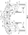
- FIG. 2 is an exploded view of the partition system 100.
- the pivot joint 102 has two pivot structures 110a, 110b, each being roughly cylindrical and having partial circular cross-sections centered on a pivot axis 115.
- Each of the pivot structures 110a, 110b engage with one of the partition wall panels 108a, 108b, permitting the engaged wall panel 108a, 108b to pivot about the pivot axis 115.
- the pivot structures 110a, 110b have a series of internal flanges 110c extending inwardly toward the pivot axis 115.
- a linking structure 112 extends between and joins the two pivot structures 110a, 110b.
- the linking structure 112 includes an outer linking edge 113 and an inner linking edge 114, each formed integrally with the pivot structures 110a and 110b.
- a stop member 118 extends outwardly from the linking structure 112 to limit the range within which wall panels 108a, 108b, which are engaged with the pivot structures 110a, 110b, can pivot about the pivot axis 115, as explained in greater detail below.
- the stop member 118 extends outwardly from the inner linking edge 114.
- the stop member has a T-shaped cross-section, with a body 118a extending outwardly from a proximal end at the inner linking edge 114 to a distal end spaced apart from the inner linking edge 114.
- the stop member 118 also has a perpendicular cross member 118b extending from the distal end of the body 118a, parallel to the inner linking edge 114.
- the stop member 118 also has a pair of flanges 118c extending from the ends of the perpendicular cross member 118b, toward the inner linking edge 114.
- the pivot joint 102 is formed as a metal extrusion, such as, but not limited to, an aluminum extrusion.
- the pivot structures 110a and 110b, the internal flanges 110c, the outer linking edge 113, the inner linking edge 114, the stop member body 118a, the stop member perpendicular cross member 118b and the flanges 118c are all formed integrally as one piece of extruded aluminum.
- the partition wall panels 108a, 108b each have an inside wall face 107a, 107b and an outside wall face 105a, 105b.
- Each of the end faces 104 extend from an end of the inside wall face 107a, 107b to a corresponding end of the outside wall face 105a, 105b.
- the end faces 104 are formed as shown in Figure 2 .
- This form is the inverse form of ports 128a, 128b of the tab connectors 109a, 109b, such that said tab connectors 109a, 109b can slide onto the end faces 104, the end faces 104 being securely received in ports 128a, 128b of the tab connectors 109a, 109b as shown in Figure 1 .
- the tab connectors 109a, 109b are described in greater detail below.
- end faces 104 can be of any shape or form, such as a rectangle, extending from the inside wall face 107a, 107b to the outside wall face 105a, 105b.
- the tab connectors 109a, 109b rely on other any other suitable connecting means to connect to the end faces 104 of the partition wall panels 108a, 108b.
- the tab connectors 109a, 109b can connect by way of a friction fit using a pair of opposed connecting flanges (not shown) that extend from the tab connector 109a, 109b to receive and grip a partition wall panel 108a, 108b.
- the tab connectors 109a, 109b comprise a pair of parallel tabs 120a, 120b, 122a, 122b for engaging the pivot joint 102.
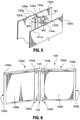
- the tabs 120a, 120b, 122a, 122b are formed integrally with the tab connectors 109a, 109b, as shown in Figure 5 , and extend from the end faces 104a, 104b when end faces 104a, 104b are securely received in port 128a, 128b of pivot arm extrusions.
- the tabs 120a, 120b, 122a, 122b can be connected to, and extend from the end faces 104a, 10b in any suitable manner, or could be formed integrally with the wall panels 108a, 108b.
- the tabs 120a, 120b, 122a, 122b extend outwardly from the end face 104a, 104b and substantially parallel to the inside wall face 107a, 107b and the outside wall face 105a, 105b.
- At least one of the tabs has an end flange adapted to engage the pivot joint.
- tabs 120a, 120b each have an end flange 124a, 124b extending inwardly toward the opposite tab 122a, 122b.
- the end flanges 124a, 124b extend such that the distance from the end of said flange to the opposite tab 122a, 122b is somewhat less than the diameter of the circular cross section of the pivot structures 110a, 110b. While said distance should be less than said diameter, it should not be so much less that the wall panels 108a, 108b cannot be snap fit onto the pivot structures 110a, 110b.
- the tabs 120a, 120b, 122a, 122b of wall panels 108a, 108b are adapted to snap fit onto the pivot structures 110a, 110b, as shown in Figure 3 .
- the partition wall panel 108a, 108b can be placed adjacent to the pivot structures 110a, 110b, such that the tabs 120a, 120b, 122a, 122b are in contact with the pivot structures 110a, 110b.
- pivot structures 110a, 110b By applying additional force on the wall panels 108a, 108b, directed inward toward the pivot structures 110a, 110b, the tabs 120a, 120b having flanges 124a, 124b deflect outward, away from the pivot structures 110a, 110b, thereby increasing the distance between flanges 124a, 124b and tabs 122a, 122b. Once said distance has increased sufficiently, pivot structures 110a, 110b will fit between tabs 120a, 122a, and tabs 120b, 122b, respectively, and the wall panels 108a, 108b will move forward into an engaged position, abutting the pivot structures 110a, 110b.
- the tabs 120a, 120b will have deflected back to their original position, and will extend forward past the apex of the circular cross-section of the pivot structures 110a, 110b.
- Flanges 124a, 124b will extend inward, beyond the apex of the circular cross section of the pivot structures 110a, 110b, thereby "gripping" said pivot structures.
- the flanges 124a, 124b can be in physical contact with the pivot structures 110a, 110b when in the engaged position, or can be spaced apart such that they will come into physical contact with pivot structure 110a, 110b, if the wall panels 108a, 108b are pulled away from said pivot structures.
- Figures 3 and 4 illustrate the range within which the wall panels 108a, 108b can be pivoted about the pivot axis 115 when the wall panels are in the engaged position.
- Figure 3 is a top view of the pivot joint 102 and the wall panels 108a, 108b, where a relative angle ⁇ between the wall panels 108a, 108b is 180 degrees.
- Figure 4 illustrates the wall panels 108a, 108b at 90 degrees to one another.
- the range of possible relative angles ⁇ between the wall panels 108a, 108b is directly related to, and dictated by, the size and shape of the stop member 118.
- the lengths of the perpendicular cross member 118b and the end flanges 118c dictate the minimum relative angle ⁇ between the wall panels 108a, 108b.
- the minimum relative angle ⁇ will be decreased or increased, respectively.
- Increasing or decreasing the length of end flanges 118c will also decrease or increase the minimum relative angle ⁇ , respectively, although to a somewhat lesser extent than changes to the length of cross member 118b.
- the tabs 120a, 120b, 122a, 122b are formed integrally with the tab connectors 109a, 109b.
- Tab connectors 109a, 109b include a connector means, for connecting the tab connectors 109a, 109b to the end faces 104 of the wall panels 108a, 108b.
- the connector means of the tab connector 109a is a port 128a.
- the port 128a is an extruded metal structure defined by an opening 130a and stepped side walls 132a, 132b that provide multiple widths w1, w2, w3 within the port 128a.
- the stepped side walls 132a, 132b are connected to an inner wall 121a and an outer wall 123a by circular recesses 134a.
- the circular recesses 134a, 134b may be used to receive and hold cap castings, which will be explained in more detail below.
- Port 128b of tab connector 109b has a similar structure as port 128a.
- any other suitable means for connecting the tab connectors 109a, 109b to the end faces 104 of the wall panels 108a, 108b can be used.
- the port 128a can be replaced with any other structure suitable for connecting inner wall 121a and outer wall 123a.
- Inner wall 121a and outer wall 123a can act as opposed connecting flanges (referred to above) that provide for a friction fit between the tab connector 109a, 109b and wall panel 108a, 108b, as described above.
- the tab connectors 109a, 109b are formed as metal extrusions, such as, but not limited to, an aluminum extrusion.
- the tabs 120a, 120b, 122a, 122b, the port 128a, 128b, the cylindrical recesses 134a, 134b, the inner wall 121a, 121b and the outer wall 123a, 123b are all formed integrally as one piece of extruded aluminum.
- each end frame member 106a, 106b has a port 146a, 146b located between an inner wall 142a, 142b and an outer wall 144a, 144b that has essentially the same structure as the port 128a shown in Figure 5 .
- the port 146a, 146b is connected to the inner wall 142a, 142b and the outer wall 144a, 144b by circular recesses 148a, 148b.
- the end frame members 106a, 106b are formed as metal extrusions, such as, but not limited to, aluminum extrusions.
- the port 146a, 146b, the cylindrical recesses 148a, 148b, the inner wall 142a, 142b and the outer wall 144a, 144b are all formed integrally as one piece of extruded aluminum.
- the ports 128a, 128b, 146a, 146b are shaped such that they can slide onto and secure the end faces 104 of the partition walls 108a, 108b. Since the ports 128a, 128b of the tab connectors 109a, 109b and the ports 146a, 146b of the end frame members 106a, 106b are of the same shape, they can be used interchangeably to secure the end faces 104 of the partition walls 108a, 108b depending on whether a pivot arm extrusion or an end frame member is required when assembling the partition system. In other words, the tab connectors 109a, 109b will be used when the end face 104 of the partition wall panel 108a, 108b will be joined to another wall panel. The end frame member 106a, 106b will be used when the end face 104 of the partition wall panel 108a, 108b is the end of the partition system.
- end frame members 106a, 106b can be connected to partition walls 108a, 108b in any suitable manner, and in the same manner that tab connectors 109a, 109b are connected to partition walls 108a, 108b.
- end frame members 106a, 106b can be connected to partition walls 108a, 108b by way of a friction fit with inner wall 142a, 142b and outer wall 144a, 144b, in the same manner that tab connectors 109a, 109b can be connected to partition walls 108a, 108b by way of a friction fit with opposed connecting flanges, such as inner wall 121a and outer wall 123a.
- the profile of said ports may also be used to receive and hold mechanical fasteners within said ports, such as but not limited to, bolt heads and nuts.
- FIG. 6 is a perspective view of the partition system, fully assembled.
- the pivot joint 102 is illustrated therein, connected to the two partition wall panels 108a, 108b.
- the end faces 104 are secured either to the tab connectors 109a, 109b or to the end frame members 106a, 106b.
- the tab connectors 109a, 109b engage with the pivot joint 102.
- Figure 6 further illustrates top frame members 150a, 150b that secure a respective top edge (not shown) of the partition wall panels 108a, 108b.
- the top frame members 150a, 150b have essentially the same structure as the end frame members 106, 106b shown in Figure 2 .
- top frame members 150a, 150b are metal extrusions, such as, but not limited to, aluminum extrusions.
- the top frame members 150a, 150b are connected to the end frame members 106a, 106b by end frame member caps 156a, 156b.
- Figure 7 is a perspective view of the end frame member cap 156a.
- the end frame member cap 156a has a square cross section with a first connecting peg 158 that is inserted into and connected to the port of the top frame member 150a using suitable fasteners.
- the end frame member cap 156a has additional connecting pegs 160 positioned at right angles to the first connecting peg 158. The additional connecting pegs 160 are received in the cylindrical recesses 148a, 148b of the end frame member 106a.
- End frame member cap 156b has a similar structure as end frame member cap 156a and connects end frame member 106b and top frame member 150b in a similar manner.
- the end frame caps 156a, 156b are metal castings, such as, but not limited to, aluminum castings.
- tab connector caps 154a, 154b connect the top frame members 150a, 150b to the tab connectors 109a, 109b.
- tab connector cap 154b has a rectangular cross section with a semicircular cutout to accommodate the pivot joint cap 152, which will be discussed in more detail below.
- Tab connector cap 154b has a first connecting peg 162 that is inserted into and connected to the port of the top frame member 150b using suitable fasteners.
- the tab connector cap 154b has additional connecting pegs 164 positioned at right angles to the first connecting peg 162. The additional connecting pegs 164 are received in the cylindrical recesses of the tab connector 109a.
- tab connector cap 154a has a similar structure as tab connector cap 154b and connects top frame member 150a and tab connector 109b in a similar manner.
- the pivot joint 102 has a pivot joint cap 152 that is more clearly illustrated in Figure 9 .
- the pivot joint cap 152 has an oval cross section with connecting pegs 166 that project downwardly from a bottom of the pivot joint cap 152.
- the connecting pegs 166 are received in slots formed by the internal flanges 110c of the two pivot structures 110a, 110b of the pivot joint 102.
- FIG 10 is a perspective view of a partition system 200 according to another embodiment.
- three partition wall panels 202a, 202b, 202c having similar structures as the partition wall panels in Figures 1 and 2 have end faces (not shown) that are secured by tab connectors 206a, 206b, 206c, 206d or by end frame members 208a, 208b.
- Tab connectors 206a, 206b, 206c, 206d engage pivot joints 204a, 204b having similar structures as the pivot joints in Figures 1 and 2 .
- the three partition wall panels 202a, 202b, 202c are also framed by top frame members 210a, 210b, 210c.
- the end frame members 208a, 208b and top frame members 210a, 210b, 210c have similar structures as the end frame members shown in Figures 1 and 2 .
- End frame member caps 212a, 212b having similar structures as the end frame member cap in Figure 7 connect the end frame members 208a, 208b to the respective top frame members 210a, 210c.
- Tab connector caps 214a, 214b, 214c, 214d having similar structures as the tab connector cap in Figure 8 connect the top frame members 210a, 210b, 210c to the respective tab connectors 206a, 206b, 206c, 206d.
- Pivot joint caps 216a, 216b having similar structures as the pivot joint cap in Figure 9 are inserted into slots in the pivot joints 204a, 204b.
- a plurality partition wall panels can be connected in series to one another at varying angles using multiple joints.
- the overall width and shape of the partition system may therefore be customized.
- An additional advantage of the partition system provided by the present disclosure is that the configuration of the partition system can be adjusted without having to disassemble any part of the system. Moreover, the partition system is easy to assemble given that the partition system comprises relatively few pieces. Fewer fasteners are required for the partition system of the present disclosure since the tab connectors attached to the end faces of the partition wall panels snap fit onto the pivot members, unlike existing partition systems.
- partition panel may be secured between the pivot joint and an end frame member, or between two pivot joints.
- two partition wall panels made of different materials are stacked one on top of the other.
- two partition wall panels are stacked vertically with a slat wall in between the two partition wall panels for securing office equipment thereto.
Landscapes
- Engineering & Computer Science (AREA)
- Architecture (AREA)
- Physics & Mathematics (AREA)
- Electromagnetism (AREA)
- Civil Engineering (AREA)
- Structural Engineering (AREA)
- Building Environments (AREA)
- Extensible Doors And Revolving Doors (AREA)
Abstract
Description
- The present disclosure relates to partition systems. More specifically, the present disclosure relates to adjustable partition systems.
- Partition systems are commonly used in control rooms, trading floors, operation centers, and other commercial settings to divide a large area into smaller, separate workspaces. Partition systems provide users with some privacy and reduce noise and other distractions, thereby potentially increasing workplace productivity and improving worker mental health.
- Many traditional partition systems come with numerous different pieces and parts, which make it more difficult and time-consuming to assemble. Further, many existing systems are not easily customizable in terms of size, shape, or configuration. Once assembled, the relative angle between the partition walls cannot be modified without partially disassembling the partition system, adjusting the angle, and reassembling the partition system in order to achieve the desired configuration, which is labour-intensive and thus has cost implications.
- Accordingly, there is a need for a partition system that is quick and easy to assemble, with relatively few parts, and can be easily adjusted to accommodate the needs of the user and the physical workspace.
- In at least one embodiment, the present disclosure provides a pivot joint for connecting partition wall panels, comprising two pivot structures having partial circular cross-sections centered on a pivot axis, each pivot structure for engaging with a wall panel and permitting an engaged wall panel to pivot about the pivot axis; a linking structure extending between and joining the two pivot structures; and a stop member extending outwardly from a proximal end at the linking structure to a distal end spaced apart from the linking structure, the stop member limiting the range within which wall panels engaged with the pivot structures can pivot about the pivot axis.
- In some embodiments, the stop member comprises a perpendicular cross member at the distal end thereof, the stop member having a T-shaped cross-section.
- In some embodiments, the stop member further comprises a pair of flanges extending from ends of the perpendicular cross member.
- In some embodiments, the pivot joint is a metal extrusion, such as an aluminum extrusion.
- The present disclosure further provides a tab connector for connecting a wall panel to a pivot joint, the tab connector comprising connector means for securing the tab connector to an end face of a wall panel, and a pair of parallel tabs extending outwardly from the connector means, at least one of said tabs having an end flange extending inwardly toward the other of said tabs, the end flange being adapted to engage the pivot joint.
- In some embodiments, the tab connector is a metal extrusion, such as an aluminum extrusion.
- The present disclosure further provides a partition system comprising at least one pivot joint, each at least one pivot joint comprising: two pivot structures having partial circular cross-sections centered on a pivot axis, each pivot structure for engaging with a wall panel and permitting an engaged wall panel to pivot about the pivot axis; a linking structure extending between and joining the two pivot structures; and a stop member extending outwardly from a proximal end at the linking structure to a distal end spaced apart from the linking structure, the stop member limiting the range within which wall panels engaged with the pivot structures can pivot about the pivot axis, the partition system further comprising a plurality of wall panels, each of said wall panels comprising a pair of parallel tabs extending substantially perpendicularly from at least one end face of the wall panel, at least one of said parallel tabs having an end flange extending inwardly toward the other of said tabs, the end flange being adapted to engage one of the pivot structures of the at least one pivot joint, each of the plurality of wall panels being pivotally connected to the at least one pivot joint.
- In some embodiments, the pair of parallel tabs of the plurality of wall panels comprises a tab connector, comprising connector means for securing the tab connector to an end face of a wall panel, and a pair of parallel tabs extending outwardly from the connector means, at least one of said tabs having an end flange extending inwardly toward the other of said tabs, the end flange being adapted to engage the at least one pivot joint.
- In some embodiments, the at least one pivot joint and the tab connectors are metal extrusions, such as aluminum extrusions.
- Aspects and embodiments of the disclosure will now be described in greater detail with reference to the accompanying diagrams, in which:
-
FIGURE 1 is a perspective view of a partition system in accordance with an embodiment of the present invention; -
FIGURE 2 is an exploded perspective view of the partition system ofFIGURE 1 ; -
FIGURE 3 is a top view of a pivot joint, tab connectors and partition wall panels of the partition system ofFIGURE 1 , with the partition wall panels at 180 degrees to one another; -
FIGURE 4 is a top view of the pivot joint, tab connectors and partition wall panels of the partition system ofFIGURE 1 , with the partition wall panels at 90 degrees to one another; -
FIGURE 5 is a perspective view of the tab connector of the partition system ofFIGURE 1 ; -
FIGURE 6 is a perspective view of the partition system ofFIGURE 1 , fully assembled; -
FIGURE 7 is a perspective view of an end frame member cap of the partition system ofFIGURE 1 ; -
FIGURE 8 is a perspective view of a tab connector cap of the partition system ofFIGURE 7 ; -
FIGURE 9 is a perspective view of a pivot joint cap of the partition system ofFIGURE 7 ; and -
FIGURE 10 is a perspective view of a partition system according to another embodiment of the present invention. - It is contemplated that the present disclosure provides an adjustable partition system that can be assembled and configured to accommodate the needs of the user and the physical workspace.
-
Figure 1 is a perspective view of apartition system 100 according to an embodiment of the present invention.Partition system 100 is comprised of apivot joint 102,partition wall panels tab connectors partition wall panels Partition wall panels end faces 104 to which thetab connectors end frame members tab connectors pivot joint 102. -
Figure 2 is an exploded view of thepartition system 100. Thepivot joint 102 has twopivot structures pivot structures partition wall panels wall panel pivot structures internal flanges 110c extending inwardly toward the pivot axis 115. - A linking
structure 112 extends between and joins the twopivot structures structure 112 includes an outer linkingedge 113 and an inner linking edge 114, each formed integrally with thepivot structures - A
stop member 118 extends outwardly from the linkingstructure 112 to limit the range within whichwall panels pivot structures stop member 118 extends outwardly from the inner linking edge 114. In this embodiment, the stop member has a T-shaped cross-section, with abody 118a extending outwardly from a proximal end at the inner linking edge 114 to a distal end spaced apart from the inner linking edge 114. Thestop member 118 also has a perpendicular cross member 118b extending from the distal end of thebody 118a, parallel to the inner linking edge 114. Thestop member 118 also has a pair offlanges 118c extending from the ends of the perpendicular cross member 118b, toward the inner linking edge 114. - In some embodiments, the
pivot joint 102 is formed as a metal extrusion, such as, but not limited to, an aluminum extrusion. In such embodiments, thepivot structures internal flanges 110c, the outer linkingedge 113, the inner linking edge 114, thestop member body 118a, the stop member perpendicular cross member 118b and theflanges 118c are all formed integrally as one piece of extruded aluminum. - The
partition wall panels inside wall face outside wall face end faces 104 extend from an end of theinside wall face outside wall face end faces 104 are formed as shown inFigure 2 . This form is the inverse form ofports tab connectors tab connectors end faces 104, theend faces 104 being securely received inports tab connectors Figure 1 . Thetab connectors - In other embodiments of the invention (not shown),
end faces 104 can be of any shape or form, such as a rectangle, extending from theinside wall face outside wall face tab connectors end faces 104 of thepartition wall panels tab connectors tab connector partition wall panel - The
tab connectors parallel tabs pivot joint 102. In the illustrated embodiment, thetabs tab connectors Figure 5 , and extend from the end faces 104a, 104b when end faces 104a, 104b are securely received inport tabs wall panels tabs inside wall face outside wall face - At least one of the tabs has an end flange adapted to engage the pivot joint. In
Figure 2 ,tabs end flange 124a, 124b extending inwardly toward theopposite tab end flanges 124a, 124b extend such that the distance from the end of said flange to theopposite tab pivot structures wall panels pivot structures - As mentioned above, the
tabs wall panels pivot structures Figure 3 . In particular, thepartition wall panel pivot structures tabs pivot structures wall panels pivot structures tabs flanges 124a, 124b deflect outward, away from thepivot structures flanges 124a, 124b andtabs pivot structures tabs tabs wall panels pivot structures tabs pivot structures Flanges 124a, 124b will extend inward, beyond the apex of the circular cross section of thepivot structures flanges 124a, 124b can be in physical contact with thepivot structures pivot structure wall panels -
Figures 3 and 4 illustrate the range within which thewall panels Figure 3 is a top view of the pivot joint 102 and thewall panels wall panels Figure 4 illustrates thewall panels - It will be appreciated that the range of possible relative angles α between the
wall panels stop member 118. In the illustrated embodiment, the lengths of the perpendicular cross member 118b and theend flanges 118c dictate the minimum relative angle α between thewall panels end flanges 118c will also decrease or increase the minimum relative angle α, respectively, although to a somewhat lesser extent than changes to the length of cross member 118b. - As mentioned previously, in the illustrated embodiment the
tabs tab connectors Tab connectors tab connectors wall panels Figure 5 , the connector means of thetab connector 109a is aport 128a. Theport 128a is an extruded metal structure defined by anopening 130a and steppedside walls port 128a. The steppedside walls inner wall 121a and anouter wall 123a bycircular recesses 134a. Thecircular recesses Port 128b oftab connector 109b has a similar structure asport 128a. - In other embodiments, any other suitable means for connecting the
tab connectors wall panels port 128a can be replaced with any other structure suitable for connectinginner wall 121a andouter wall 123a.Inner wall 121a andouter wall 123a can act as opposed connecting flanges (referred to above) that provide for a friction fit between thetab connector wall panel - In some embodiments, the
tab connectors tabs port cylindrical recesses inner wall outer wall - Referring again to
Figure 2 , eachend frame member port inner wall outer wall port 128a shown inFigure 5 . Theport inner wall outer wall circular recesses - In some embodiments, the
end frame members port cylindrical recesses inner wall outer wall - As mentioned previously, the
ports partition walls ports tab connectors ports end frame members partition walls tab connectors end face 104 of thepartition wall panel end frame member end face 104 of thepartition wall panel - It will be appreciated that
end frame members walls tab connectors walls end frame members walls inner wall outer wall tab connectors walls inner wall 121a andouter wall 123a. - In embodiments where
ports -
Figure 6 is a perspective view of the partition system, fully assembled. The pivot joint 102 is illustrated therein, connected to the twopartition wall panels tab connectors end frame members tab connectors pivot joint 102.Figure 6 further illustratestop frame members partition wall panels top frame members end frame members 106, 106b shown inFigure 2 . In some embodiments,top frame members - The
top frame members end frame members frame member caps Figure 7 is a perspective view of the endframe member cap 156a. The endframe member cap 156a has a square cross section with a first connectingpeg 158 that is inserted into and connected to the port of thetop frame member 150a using suitable fasteners. The endframe member cap 156a has additional connectingpegs 160 positioned at right angles to the first connectingpeg 158. The additional connectingpegs 160 are received in thecylindrical recesses end frame member 106a. Endframe member cap 156b has a similar structure as endframe member cap 156a and connectsend frame member 106b andtop frame member 150b in a similar manner. In some embodiments, theend frame caps - Turning back to
Figure 6 ,tab connector caps top frame members tab connectors Figure 8 ,tab connector cap 154b has a rectangular cross section with a semicircular cutout to accommodate the pivotjoint cap 152, which will be discussed in more detail below.Tab connector cap 154b has a first connectingpeg 162 that is inserted into and connected to the port of thetop frame member 150b using suitable fasteners. Thetab connector cap 154b has additional connectingpegs 164 positioned at right angles to the first connectingpeg 162. The additional connectingpegs 164 are received in the cylindrical recesses of thetab connector 109a.tab connector cap 154a has a similar structure astab connector cap 154b and connectstop frame member 150a andtab connector 109b in a similar manner. - Referring again to
Figure 6 , the pivot joint 102 has a pivotjoint cap 152 that is more clearly illustrated inFigure 9 . The pivotjoint cap 152 has an oval cross section with connectingpegs 166 that project downwardly from a bottom of the pivotjoint cap 152. The connectingpegs 166 are received in slots formed by theinternal flanges 110c of the twopivot structures pivot joint 102. -
Figure 10 is a perspective view of apartition system 200 according to another embodiment. In this embodiment, threepartition wall panels Figures 1 and2 have end faces (not shown) that are secured bytab connectors end frame members Tab connectors Figures 1 and2 . The threepartition wall panels top frame members end frame members top frame members Figures 1 and2 . Endframe member caps Figure 7 connect theend frame members top frame members Tab connector caps Figure 8 connect thetop frame members respective tab connectors joint caps Figure 9 are inserted into slots in the pivot joints 204a, 204b. - In at least one embodiment, it is contemplated that a plurality partition wall panels can be connected in series to one another at varying angles using multiple joints. The overall width and shape of the partition system may therefore be customized. An additional advantage of the partition system provided by the present disclosure is that the configuration of the partition system can be adjusted without having to disassemble any part of the system. Moreover, the partition system is easy to assemble given that the partition system comprises relatively few pieces. Fewer fasteners are required for the partition system of the present disclosure since the tab connectors attached to the end faces of the partition wall panels snap fit onto the pivot members, unlike existing partition systems.
- It is further contemplated that more than one partition panel may be secured between the pivot joint and an end frame member, or between two pivot joints. For example, in one embodiment, two partition wall panels made of different materials are stacked one on top of the other. In another embodiment, two partition wall panels are stacked vertically with a slat wall in between the two partition wall panels for securing office equipment thereto.
- The embodiments described herein are intended to be illustrative of the present compositions and are not intended to limit the scope of the present disclosure. Various modifications and changes consistent with the description as a whole and which are readily apparent to the person of skill in the art are intended to be included. The appended claims should not be limited by the specific embodiments set forth in the examples but should be given the broadest interpretation consistent with the description as a whole.
Claims (12)
- A pivot joint for connecting partition wall panels, comprising:- two pivot structures having partial circular cross-sections centered on a pivot axis, each pivot structure for engaging with a wall panel and permitting an engaged wall panel to pivot about the pivot axis;- a linking structure extending between and joining the two pivot structures; and- a stop member extending outwardly from a proximal end at the linking structure to a distal end spaced apart from the linking structure, the stop member limiting the range within which wall panels engaged with the pivot structures can pivot about the pivot axis.
- The pivot joint of claim 1, wherein the stop member comprises a perpendicular cross member at the distal end thereof, the stop member having a T-shaped cross-section.
- The pivot joint of claim 2, wherein the stop member further comprises a pair of flanges extending from ends of the perpendicular cross member.
- The pivot joint of any one of claims 1 to 3, wherein the pivot joint is a metal extrusion.
- The pivot joint of claim 4, wherein the metal extrusion is an aluminum extrusion.
- A tab connector for connecting a wall panel to a pivot joint, the tab connector comprising connector means for securing the tab connector to an end face of a wall panel, and a pair of parallel tabs extending outwardly from the connector means, at least one of said tabs having an end flange extending inwardly toward the other of said tabs, the end flange being adapted to engage the pivot joint.
- The tab connector of claim 6, wherein the tab connector is a metal extrusion.
- The tab connector of claim 7, wherein the metal extrusion is an aluminum extrusion.
- A partition system comprising:- at least one pivot joint, each at least one pivot joint comprising:- two pivot structures having partial circular cross-sections centered on a pivot axis, each pivot structure for engaging with a wall panel and permitting an engaged wall panel to pivot about the pivot axis;- a linking structure extending between and joining the two pivot structures; and- a stop member extending outwardly from a proximal end at the linking structure to a distal end spaced apart from the linking structure, the stop member limiting the range within which wall panels engaged with the pivot structures can pivot about the pivot axis; and- a plurality of wall panels, each of said wall panels comprising a pair of parallel tabs extending substantially perpendicularly from at least one end face of the wall panel, at least one of said parallel tabs having an end flange extending inwardly toward the other of said tabs, the end flange being adapted to engage one of the pivot structures of the at least one pivot joint;- each of the plurality of wall panels being pivotally connected to one of the pivot structures of the at least one pivot joint.
- The partition wall system of claim 9, wherein the pair of parallel tabs of the plurality of wall panels comprises a tab connector of any one of claims 6-8 secured to the end faces of the wall panels.
- The partition system of claim 10, wherein the at least one pivot joint and the tab connector are metal extrusions.
- The partition system of claim 11, wherein the metal extrusions are aluminum extrusions.
Applications Claiming Priority (1)
| Application Number | Priority Date | Filing Date | Title |
|---|---|---|---|
| US202063076720P | 2020-09-10 | 2020-09-10 |
Publications (2)
| Publication Number | Publication Date |
|---|---|
| EP3967819A1 true EP3967819A1 (en) | 2022-03-16 |
| EP3967819B1 EP3967819B1 (en) | 2025-08-20 |
Family
ID=78008072
Family Applications (1)
| Application Number | Title | Priority Date | Filing Date |
|---|---|---|---|
| EP21196024.0A Active EP3967819B1 (en) | 2020-09-10 | 2021-09-10 | Pivot joint for partition system |
Country Status (2)
| Country | Link |
|---|---|
| US (1) | US12371902B2 (en) |
| EP (1) | EP3967819B1 (en) |
Families Citing this family (2)
| Publication number | Priority date | Publication date | Assignee | Title |
|---|---|---|---|---|
| ES1274119Y (en) * | 2021-06-22 | 2021-10-19 | Spazia Glass S L | MODULAR SCREEN |
| BE1031369B1 (en) * | 2023-02-23 | 2024-09-25 | Aluvision N V | Holder for connecting element for stand construction profile |
Citations (3)
| Publication number | Priority date | Publication date | Assignee | Title |
|---|---|---|---|---|
| US543906A (en) * | 1895-08-06 | Algenon s | ||
| US3889315A (en) * | 1974-04-15 | 1975-06-17 | Wilfred Stouffer | Safety door hinge |
| EP0168354A1 (en) * | 1984-06-05 | 1986-01-15 | EFFE - ELLE S.p.A. | Folding partition system composed of a series of adjacent panels |
Family Cites Families (18)
| Publication number | Priority date | Publication date | Assignee | Title |
|---|---|---|---|---|
| US3605851A (en) | 1969-09-22 | 1971-09-20 | Rosemount Partitions Inc | Divider screen assembly |
| US3696855A (en) | 1970-10-16 | 1972-10-10 | Gen Telephone Co Of Calif | Interior modular panel assemblies |
| BE785766A (en) | 1971-07-02 | 1973-01-03 | Westinghouse Electric Corp | IMPROVEMENTS TO SPACE DIVISION SYSTEMS |
| US3889736A (en) * | 1973-05-18 | 1975-06-17 | Firks Exhibitions Inc | Display screen for exhibits and the like |
| US4103465A (en) * | 1977-08-25 | 1978-08-01 | Greyhound Exhibitgroup, Inc. | Modular panel display system |
| US4606394A (en) * | 1981-09-18 | 1986-08-19 | Marler Haley Exposystems Ltd. | Barrier systems and the like |
| US4594829A (en) * | 1983-08-05 | 1986-06-17 | Herrgord Donald E | Joint interlocking system |
| GB2159573B (en) | 1984-05-30 | 1987-09-16 | Venesta International Componen | Improvements in and relating to hinges and door stop assemblies |
| GB2176220B (en) * | 1985-06-11 | 1988-09-14 | Alan Raymond Notley | Screen for partitioning open floor areas |
| US4601145A (en) * | 1985-08-05 | 1986-07-22 | Roger Wilcox | Adjustable room partition |
| DE3613574A1 (en) * | 1986-04-22 | 1987-12-23 | Theodor Puschkarski | CONNECTING ELEMENT TO CONNECT TWO PANELS |
| US4774792A (en) * | 1986-08-25 | 1988-10-04 | Ballance Design Limited | Exhibition display apparatus |
| CA2054152C (en) * | 1991-10-24 | 1995-10-10 | Robert Dagenais | Hinge construction for a folding closure assembly |
| US5287909A (en) * | 1992-12-09 | 1994-02-22 | Steelcase Inc. | Freestanding privacy screen |
| US5363612A (en) * | 1993-02-12 | 1994-11-15 | Erickson Arvid L | Display panel assembly |
| DE19844027A1 (en) * | 1998-09-25 | 2000-03-30 | Preform Raumgliederungssysteme | Connecting element for connecting two components of a partition and use of such a connecting element |
| US20060254176A1 (en) * | 2005-04-13 | 2006-11-16 | Sing Bee Enterprise Co., Ltd. | Combinative partition |
| US9062484B2 (en) * | 2013-06-14 | 2015-06-23 | Qualitas Manufacturing, Inc. | Accordion shutter hinge assembly |
-
2021
- 2021-09-09 US US17/470,610 patent/US12371902B2/en active Active
- 2021-09-10 EP EP21196024.0A patent/EP3967819B1/en active Active
Patent Citations (3)
| Publication number | Priority date | Publication date | Assignee | Title |
|---|---|---|---|---|
| US543906A (en) * | 1895-08-06 | Algenon s | ||
| US3889315A (en) * | 1974-04-15 | 1975-06-17 | Wilfred Stouffer | Safety door hinge |
| EP0168354A1 (en) * | 1984-06-05 | 1986-01-15 | EFFE - ELLE S.p.A. | Folding partition system composed of a series of adjacent panels |
Also Published As
| Publication number | Publication date |
|---|---|
| EP3967819B1 (en) | 2025-08-20 |
| US20220074200A1 (en) | 2022-03-10 |
| US12371902B2 (en) | 2025-07-29 |
Similar Documents
| Publication | Publication Date | Title |
|---|---|---|
| EP3967819B1 (en) | Pivot joint for partition system | |
| US6854233B2 (en) | Quick-connect panel system | |
| US8961259B2 (en) | Toy building blocks | |
| CN108601984B (en) | Modular frame connectors and systems using them | |
| US4463684A (en) | Horizontal shelf unit for handling papers | |
| US20080168633A1 (en) | Elastic fastener and actuator module using the same | |
| US8130996B2 (en) | Loud speaker group assembled from a plurality of loud speakers with snap-on connections | |
| JP4402838B2 (en) | Toy assembly set | |
| US20050129460A1 (en) | Modular frame corners | |
| WO2011110972A1 (en) | Method and system for a modular connector | |
| AU2018263295A1 (en) | Panel systems and components | |
| US5687859A (en) | Non-racking panel display device | |
| CA1302039C (en) | Connector for suspension ceiling grid | |
| EP3633809B1 (en) | Cable ladder | |
| GB2283071A (en) | Joining of panels | |
| GB2159573A (en) | Improvements in and relating to hinges and door stop assemblies | |
| US20030159378A1 (en) | Method and apparatus for providing a modular storage system | |
| US20190078328A1 (en) | Screen assembly | |
| EP3381324A1 (en) | An improved complex of elements for associating a profiled member | |
| KR102522704B1 (en) | Tube retainers, tube retainer sets, and tube management systems | |
| EP0169697B1 (en) | Jointing system | |
| EP0383427B1 (en) | Display panel assembly | |
| EP3885620B1 (en) | Tube retainers, tube retainer sets, and tube management systems | |
| EP1016055B1 (en) | Block | |
| EP0163616B1 (en) | Tubular elements and joints for their mutual articulated connection to form a partition wall of variable shape |
Legal Events
| Date | Code | Title | Description |
|---|---|---|---|
| PUAI | Public reference made under article 153(3) epc to a published international application that has entered the european phase |
Free format text: ORIGINAL CODE: 0009012 |
|
| STAA | Information on the status of an ep patent application or granted ep patent |
Free format text: STATUS: THE APPLICATION HAS BEEN PUBLISHED |
|
| AK | Designated contracting states |
Kind code of ref document: A1 Designated state(s): AL AT BE BG CH CY CZ DE DK EE ES FI FR GB GR HR HU IE IS IT LI LT LU LV MC MK MT NL NO PL PT RO RS SE SI SK SM TR |
|
| STAA | Information on the status of an ep patent application or granted ep patent |
Free format text: STATUS: REQUEST FOR EXAMINATION WAS MADE |
|
| 17P | Request for examination filed |
Effective date: 20220916 |
|
| RBV | Designated contracting states (corrected) |
Designated state(s): AL AT BE BG CH CY CZ DE DK EE ES FI FR GB GR HR HU IE IS IT LI LT LU LV MC MK MT NL NO PL PT RO RS SE SI SK SM TR |
|
| STAA | Information on the status of an ep patent application or granted ep patent |
Free format text: STATUS: EXAMINATION IS IN PROGRESS |
|
| 17Q | First examination report despatched |
Effective date: 20241011 |
|
| GRAP | Despatch of communication of intention to grant a patent |
Free format text: ORIGINAL CODE: EPIDOSNIGR1 |
|
| STAA | Information on the status of an ep patent application or granted ep patent |
Free format text: STATUS: GRANT OF PATENT IS INTENDED |
|
| GRAJ | Information related to disapproval of communication of intention to grant by the applicant or resumption of examination proceedings by the epo deleted |
Free format text: ORIGINAL CODE: EPIDOSDIGR1 |
|
| STAA | Information on the status of an ep patent application or granted ep patent |
Free format text: STATUS: EXAMINATION IS IN PROGRESS |
|
| GRAP | Despatch of communication of intention to grant a patent |
Free format text: ORIGINAL CODE: EPIDOSNIGR1 |
|
| STAA | Information on the status of an ep patent application or granted ep patent |
Free format text: STATUS: GRANT OF PATENT IS INTENDED |
|
| GRAS | Grant fee paid |
Free format text: ORIGINAL CODE: EPIDOSNIGR3 |
|
| INTG | Intention to grant announced |
Effective date: 20250617 |
|
| GRAA | (expected) grant |
Free format text: ORIGINAL CODE: 0009210 |
|
| STAA | Information on the status of an ep patent application or granted ep patent |
Free format text: STATUS: THE PATENT HAS BEEN GRANTED |
|
| INTG | Intention to grant announced |
Effective date: 20250711 |
|
| AK | Designated contracting states |
Kind code of ref document: B1 Designated state(s): AL AT BE BG CH CY CZ DE DK EE ES FI FR GB GR HR HU IE IS IT LI LT LU LV MC MK MT NL NO PL PT RO RS SE SI SK SM TR |
|
| REG | Reference to a national code |
Ref country code: GB Ref legal event code: FG4D |
|
| REG | Reference to a national code |
Ref country code: CH Ref legal event code: EP |
|
| REG | Reference to a national code |
Ref country code: DE Ref legal event code: R096 Ref document number: 602021036502 Country of ref document: DE |
|
| REG | Reference to a national code |
Ref country code: IE Ref legal event code: FG4D |
|
| PGFP | Annual fee paid to national office [announced via postgrant information from national office to epo] |
Ref country code: GB Payment date: 20250828 Year of fee payment: 5 |
|
| PGFP | Annual fee paid to national office [announced via postgrant information from national office to epo] |
Ref country code: AT Payment date: 20251020 Year of fee payment: 5 |
|
| REG | Reference to a national code |
Ref country code: NL Ref legal event code: MP Effective date: 20250820 |
|
| PG25 | Lapsed in a contracting state [announced via postgrant information from national office to epo] |
Ref country code: IS Free format text: LAPSE BECAUSE OF FAILURE TO SUBMIT A TRANSLATION OF THE DESCRIPTION OR TO PAY THE FEE WITHIN THE PRESCRIBED TIME-LIMIT Effective date: 20251220 |
|
| PG25 | Lapsed in a contracting state [announced via postgrant information from national office to epo] |
Ref country code: NO Free format text: LAPSE BECAUSE OF FAILURE TO SUBMIT A TRANSLATION OF THE DESCRIPTION OR TO PAY THE FEE WITHIN THE PRESCRIBED TIME-LIMIT Effective date: 20251120 |
|
| REG | Reference to a national code |
Ref country code: LT Ref legal event code: MG9D |
|
| PG25 | Lapsed in a contracting state [announced via postgrant information from national office to epo] |
Ref country code: PT Free format text: LAPSE BECAUSE OF FAILURE TO SUBMIT A TRANSLATION OF THE DESCRIPTION OR TO PAY THE FEE WITHIN THE PRESCRIBED TIME-LIMIT Effective date: 20251222 |
|
| PG25 | Lapsed in a contracting state [announced via postgrant information from national office to epo] |
Ref country code: FI Free format text: LAPSE BECAUSE OF FAILURE TO SUBMIT A TRANSLATION OF THE DESCRIPTION OR TO PAY THE FEE WITHIN THE PRESCRIBED TIME-LIMIT Effective date: 20250820 |
|
| PG25 | Lapsed in a contracting state [announced via postgrant information from national office to epo] |
Ref country code: NL Free format text: LAPSE BECAUSE OF FAILURE TO SUBMIT A TRANSLATION OF THE DESCRIPTION OR TO PAY THE FEE WITHIN THE PRESCRIBED TIME-LIMIT Effective date: 20250820 Ref country code: HR Free format text: LAPSE BECAUSE OF FAILURE TO SUBMIT A TRANSLATION OF THE DESCRIPTION OR TO PAY THE FEE WITHIN THE PRESCRIBED TIME-LIMIT Effective date: 20250820 |
|
| PG25 | Lapsed in a contracting state [announced via postgrant information from national office to epo] |
Ref country code: GR Free format text: LAPSE BECAUSE OF FAILURE TO SUBMIT A TRANSLATION OF THE DESCRIPTION OR TO PAY THE FEE WITHIN THE PRESCRIBED TIME-LIMIT Effective date: 20251121 |
|
| PG25 | Lapsed in a contracting state [announced via postgrant information from national office to epo] |
Ref country code: SE Free format text: LAPSE BECAUSE OF FAILURE TO SUBMIT A TRANSLATION OF THE DESCRIPTION OR TO PAY THE FEE WITHIN THE PRESCRIBED TIME-LIMIT Effective date: 20250820 |
|
| PG25 | Lapsed in a contracting state [announced via postgrant information from national office to epo] |
Ref country code: LV Free format text: LAPSE BECAUSE OF FAILURE TO SUBMIT A TRANSLATION OF THE DESCRIPTION OR TO PAY THE FEE WITHIN THE PRESCRIBED TIME-LIMIT Effective date: 20250820 |
|
| PG25 | Lapsed in a contracting state [announced via postgrant information from national office to epo] |
Ref country code: BG Free format text: LAPSE BECAUSE OF FAILURE TO SUBMIT A TRANSLATION OF THE DESCRIPTION OR TO PAY THE FEE WITHIN THE PRESCRIBED TIME-LIMIT Effective date: 20250820 Ref country code: PL Free format text: LAPSE BECAUSE OF FAILURE TO SUBMIT A TRANSLATION OF THE DESCRIPTION OR TO PAY THE FEE WITHIN THE PRESCRIBED TIME-LIMIT Effective date: 20250820 |
|
| PG25 | Lapsed in a contracting state [announced via postgrant information from national office to epo] |
Ref country code: RS Free format text: LAPSE BECAUSE OF FAILURE TO SUBMIT A TRANSLATION OF THE DESCRIPTION OR TO PAY THE FEE WITHIN THE PRESCRIBED TIME-LIMIT Effective date: 20251120 |
|
| PG25 | Lapsed in a contracting state [announced via postgrant information from national office to epo] |
Ref country code: ES Free format text: LAPSE BECAUSE OF FAILURE TO SUBMIT A TRANSLATION OF THE DESCRIPTION OR TO PAY THE FEE WITHIN THE PRESCRIBED TIME-LIMIT Effective date: 20250820 |
|
| REG | Reference to a national code |
Ref country code: AT Ref legal event code: MK05 Ref document number: 1827437 Country of ref document: AT Kind code of ref document: T Effective date: 20250820 |
|
| PG25 | Lapsed in a contracting state [announced via postgrant information from national office to epo] |
Ref country code: RO Free format text: LAPSE BECAUSE OF FAILURE TO SUBMIT A TRANSLATION OF THE DESCRIPTION OR TO PAY THE FEE WITHIN THE PRESCRIBED TIME-LIMIT Effective date: 20250820 |
|
| PG25 | Lapsed in a contracting state [announced via postgrant information from national office to epo] |
Ref country code: SM Free format text: LAPSE BECAUSE OF FAILURE TO SUBMIT A TRANSLATION OF THE DESCRIPTION OR TO PAY THE FEE WITHIN THE PRESCRIBED TIME-LIMIT Effective date: 20250820 |
|
| PG25 | Lapsed in a contracting state [announced via postgrant information from national office to epo] |
Ref country code: DK Free format text: LAPSE BECAUSE OF FAILURE TO SUBMIT A TRANSLATION OF THE DESCRIPTION OR TO PAY THE FEE WITHIN THE PRESCRIBED TIME-LIMIT Effective date: 20250820 |
|
| PG25 | Lapsed in a contracting state [announced via postgrant information from national office to epo] |
Ref country code: AT Free format text: LAPSE BECAUSE OF FAILURE TO SUBMIT A TRANSLATION OF THE DESCRIPTION OR TO PAY THE FEE WITHIN THE PRESCRIBED TIME-LIMIT Effective date: 20250820 |
|
| PG25 | Lapsed in a contracting state [announced via postgrant information from national office to epo] |
Ref country code: IT Free format text: LAPSE BECAUSE OF FAILURE TO SUBMIT A TRANSLATION OF THE DESCRIPTION OR TO PAY THE FEE WITHIN THE PRESCRIBED TIME-LIMIT Effective date: 20250820 |
|
| PG25 | Lapsed in a contracting state [announced via postgrant information from national office to epo] |
Ref country code: CZ Free format text: LAPSE BECAUSE OF FAILURE TO SUBMIT A TRANSLATION OF THE DESCRIPTION OR TO PAY THE FEE WITHIN THE PRESCRIBED TIME-LIMIT Effective date: 20250820 |
|
| PG25 | Lapsed in a contracting state [announced via postgrant information from national office to epo] |
Ref country code: EE Free format text: LAPSE BECAUSE OF FAILURE TO SUBMIT A TRANSLATION OF THE DESCRIPTION OR TO PAY THE FEE WITHIN THE PRESCRIBED TIME-LIMIT Effective date: 20250820 Ref country code: SK Free format text: LAPSE BECAUSE OF FAILURE TO SUBMIT A TRANSLATION OF THE DESCRIPTION OR TO PAY THE FEE WITHIN THE PRESCRIBED TIME-LIMIT Effective date: 20250820 |
|
| REG | Reference to a national code |
Ref country code: CH Ref legal event code: H13 Free format text: ST27 STATUS EVENT CODE: U-0-0-H10-H13 (AS PROVIDED BY THE NATIONAL OFFICE) Effective date: 20260504 |