EP3967604A1 - Parachute riser assembly - Google Patents
Parachute riser assembly Download PDFInfo
- Publication number
- EP3967604A1 EP3967604A1 EP21196614.8A EP21196614A EP3967604A1 EP 3967604 A1 EP3967604 A1 EP 3967604A1 EP 21196614 A EP21196614 A EP 21196614A EP 3967604 A1 EP3967604 A1 EP 3967604A1
- Authority
- EP
- European Patent Office
- Prior art keywords
- riser
- parachute
- curtain
- assembly
- coupled
- Prior art date
- Legal status (The legal status is an assumption and is not a legal conclusion. Google has not performed a legal analysis and makes no representation as to the accuracy of the status listed.)
- Withdrawn
Links
- 230000004044 response Effects 0.000 claims abstract description 19
- 230000001419 dependent effect Effects 0.000 claims 1
- 101000714541 Danio rerio Cadherin-2 Proteins 0.000 description 50
- 230000008901 benefit Effects 0.000 description 8
- 230000007704 transition Effects 0.000 description 4
- 238000000034 method Methods 0.000 description 3
- 238000000926 separation method Methods 0.000 description 2
- 230000006978 adaptation Effects 0.000 description 1
- 230000000712 assembly Effects 0.000 description 1
- 238000000429 assembly Methods 0.000 description 1
- 238000010276 construction Methods 0.000 description 1
- 230000008878 coupling Effects 0.000 description 1
- 238000010168 coupling process Methods 0.000 description 1
- 238000005859 coupling reaction Methods 0.000 description 1
- 231100001261 hazardous Toxicity 0.000 description 1
- 230000009191 jumping Effects 0.000 description 1
- 230000008569 process Effects 0.000 description 1
Images


Classifications
-
- B—PERFORMING OPERATIONS; TRANSPORTING
- B64—AIRCRAFT; AVIATION; COSMONAUTICS
- B64D—EQUIPMENT FOR FITTING IN OR TO AIRCRAFT; FLIGHT SUITS; PARACHUTES; ARRANGEMENT OR MOUNTING OF POWER PLANTS OR PROPULSION TRANSMISSIONS IN AIRCRAFT
- B64D17/00—Parachutes
-
- B—PERFORMING OPERATIONS; TRANSPORTING
- B64—AIRCRAFT; AVIATION; COSMONAUTICS
- B64D—EQUIPMENT FOR FITTING IN OR TO AIRCRAFT; FLIGHT SUITS; PARACHUTES; ARRANGEMENT OR MOUNTING OF POWER PLANTS OR PROPULSION TRANSMISSIONS IN AIRCRAFT
- B64D17/00—Parachutes
- B64D17/22—Load suspension
- B64D17/24—Rigging lines
-
- B—PERFORMING OPERATIONS; TRANSPORTING
- B64—AIRCRAFT; AVIATION; COSMONAUTICS
- B64D—EQUIPMENT FOR FITTING IN OR TO AIRCRAFT; FLIGHT SUITS; PARACHUTES; ARRANGEMENT OR MOUNTING OF POWER PLANTS OR PROPULSION TRANSMISSIONS IN AIRCRAFT
- B64D17/00—Parachutes
- B64D17/22—Load suspension
- B64D17/30—Harnesses
Definitions
- the present disclosure relates to parachute riser assemblies, and in particular to providing neck support to parachute users in order to prevent neck hyperextension.
- Various aircraft include one or more ejection seats configured to eject a pilot or other occupant from the aircraft during an emergency.
- ejection seats configured to eject a pilot or other occupant from the aircraft during an emergency.
- the subsequent separation of the pilot from the ejection seat often results in the pilot experiencing neck hyperextensions in response to rapid tensioning of the parachute risers.
- This problem may be exacerbated by the fact that the weight of a pilot's helmet has been increasing as more sophisticated equipment and components are integrated and incorporated with the pilot's helmet (e.g., helmet mounted display components, etc.).
- the parachute riser assembly may include a left riser, a right riser, and a curtain.
- the left riser is configured to extend from a canopy and is configured to be coupled to a left attachment point of a harness worn by a user, according to various embodiments.
- the right riser is configured to extend from the canopy and is configured to be coupled to a right attachment point of the harness, according to various embodiments.
- the curtain may be coupled to and may extend between the left riser and the right riser.
- a portion of the curtain is configured to move along the left riser and the right riser from a furled state to an unfurled state in response to tensioning the left riser and the right riser.
- the curtain comprises a top edge and a bottom edge, wherein the bottom edge is the portion of the curtain that is configured to move along the left riser and the right riser such that the bottom edge moves down towards the harness along the left riser and the right riser in response to tensioning the left riser and the right riser via deployment of the parachute.
- the top edge of the curtain is non-movably coupled to the left riser and the right riser such that the top edge is prevented from moving relative to the left riser and the right riser.
- At least the bottom edge of the curtain comprises a sleeve structure that envelopes respective sections of the left riser and the right riser such that the sleeve structure enables the bottom edge of the curtain to be slidably coupled to the left riser and the right riser to allow the bottom edge of the curtain to slide along the left riser and the right riser towards the harness in response to deployment of the parachute.
- the parachute riser assembly further includes respective draw straps extending along the left riser and the right riser, wherein each draw strap of the respective draw straps comprises a first end coupled to a respective riser and a second end directly coupled to the portion of the curtain.
- the parachute riser assembly further includes respective links affixed to the left riser and the right riser proximate the harness, wherein each draw strap of the respective draw straps extends through and bends substantially 180 degrees about one link of the respective links.
- a first length of the left riser and the right riser, as measured between the respective links and the first end of the respective draw straps, is greater than a second length of the respective draw straps, also as measured between the respective links and the first end of the respective draw straps, according to various embodiments.
- the second length of the respective draw straps is increased as the second end of the respective draw straps is pulled down towards the harness, thereby transitioning the curtain to the unfurled state and substantially equalizing the first length and the second length, according to various embodiments.
- a shape of a bottom edge of the curtain extending between the left riser and the right riser in the unfurled state is arcuate.
- the left riser and the right riser are rear risers.
- the parachute riser assembly further includes respective draw straps extending along the left riser and the right riser, wherein each draw strap of the respective draw straps comprises a first end coupled to a respective riser and a second end directly coupled to the portion of the curtain.
- a parachute that includes a canopy, a left riser, a right riser, a curtain, and respective draw straps.
- the left riser may extend from the canopy and may be configured to be coupled to a left attachment point of a harness worn by a user.
- the right riser may extend from the canopy and may be configured to be coupled to a right attachment point of the harness.
- the curtain may be coupled to and may extend between the left riser and the right riser.
- the respective draw straps may extend along the left riser and the right riser, wherein each draw strap of the respective draw straps comprises a first end coupled to a respective riser and a second end directly coupled to a portion of the curtain.
- the portion of the curtain is configured to move along the left riser and the right riser from a furled state to an unfurled state in response to tensioning the left riser and the right riser.
- the parachute further includes respective links affixed to the left riser and the right riser proximate the harness, wherein each draw strap of the respective draw straps extends through and bends substantially 180 degrees about one link of the respective links.
- a first length of the left riser and the right riser, as measured between the respective links and the first end of the respective draw straps is greater than a second length of the respective draw straps, also as measured between the respective links and the first end of the respective draw straps.
- the second length of the respective draw straps in response to tensioning the left riser and the right riser, is increased as the second end of the respective draw straps is pulled down towards the harness, thereby transitioning the curtain to the unfurled state and substantially equalizing the first length and the second length.
- a parachute riser assembly configured to support the head and/or neck of a parachute user during parachute deployment.
- the parachute riser assembly generally includes a curtain that transitions from a furled state to an unfurled state in response to tensioning the risers of the parachute (e.g., in response to parachute deployment), according to various embodiments.
- FIG. 1 is a schematic view of an aircraft ejection event, in accordance with various embodiments.
- FIG. 1 illustrates an aircraft ejection system 100, in accordance with various embodiments.
- the aircraft ejection system 100 may be installed in an aircraft 102 to safely expel an ejection seat 106 and a user 110 of the ejection seat 106 from a cockpit 104 of the aircraft 102.
- the ejection seat 106 may be urged from the cockpit 104 by a propulsion system 108.
- the aircraft ejection system 100 may include a parachute 116. In various embodiments, prior to deployment of the parachute 116, a portion of the parachute 116 may be stored within the ejection seat 106.
- a parachute riser assembly 200 is provided.
- the parachute riser assembly 200 is configured to extend from the canopy of a parachute 116 (which may be stored in the ejection seat 106) to a harness 50 worn by the user 110 (which may be a pilot, a crewperson, or other parachute user), according to various embodiments.
- a harness 50 worn by the user 110 which may be a pilot, a crewperson, or other parachute user
- inertial real straps 64 and roller fittings 62 are also shown inertial real straps 64 and roller fittings 62.
- the roller fittings 62 are coupled to the harness 50 and the inertial real straps 64 extend from the roller fittings 62 to the seat 106 in order to secure the user 110 to the seat 106.
- the inertial real straps 64 are configured to be released during seat-user separation after ejection.
- FIGS. 2B , 3A , 3B , 4A, and 4C show the roller fittings 62, but the inertial real straps 64 are purposefully omitted from these figures in order to avoid obscuring the clarity of the depiction of the parachute riser assembly 200.
- the parachute riser assembly 200 generally includes one or more left risers 210 and one or more right risers 220 that extend from the canopy to an attachment point 51 of the harness 50 worn by the user 110, according to various embodiments.
- the one or more left risers 210 may include a left forward riser 211 and a left rear riser 212, while the one or more right risers 220 may include a right forward riser 221 and a right rear riser 222.
- the parachute riser assembly 200 may include a curtain 230 coupled to and between the left rear riser 212 and the right rear riser 222.
- the curtain 230 is generally configured to support the head 111 and/or neck 112 of the user 110 during deployment of the parachute, according to various embodiments. That is, during parachute deployment with conventional risers, the head of the parachute user would be pushed back between the risers in response to the deployment force of the parachute. With the curtain 230 in place between the risers, the rearward movement of head 111 and/or neck 112 of the user 110 is prevented (or at least mitigated) by the presence of the curtain 230.
- the curtain 230 is coupled between the left rear riser 212 and the right rear riser 222 (as opposed to the corresponding forward risers, which would result in the head 111 and/or neck 112 of the user 110 being pushed to far forward or potentially covering the face of the user 110). Accordingly, the terms “left riser” and “right riser” as used below and in the claims refer to the respective rear risers 212, 222.
- the attachment point 51 to which the parachute riser assembly 200 is coupled is forward of the user's shoulders. That is, the attachment point 51 may be proximate the chest of the user.
- the curtain 230 comprises a bottom edge 232 and a top edge 234 ( FIG 3A ).
- the terms “bottom,” “down,” “top,” and “up” refer to relative positions of various components based on a standard orientation of the curtain 230 with the parachute in a deployed state, with the riser assembly 200 extending upward from the attachment point 51 to the canopy above the user 110.
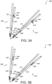
- the curtain 230 comprises a portion that is configured to move (e.g., slide) along the risers 212, 222 from a furled state to an unfurled state, as described in more detail below with reference to FIGS. 3A and 3B .
- the parachute riser assembly 200 further includes respective draw straps 240 and respective links 250 to facilitate the expansion of the curtain 230, as explained in greater detail below starting with reference to FIGS. 3A and 3B .
- the moveable portion of the curtain 230 is configured to move down towards the user.
- one of the benefits of having the curtain 230 comprise this downward-expanding configuration is that in the furled state, the bottom edge 232 of the curtain 230 remains a distance away from the neck 112 of the user (e.g., see FIG. 2B , with the bottom edge 232 of the curtain not being in direct contact with the neck 112 of the user).
- Such a configuration may provide various comfort and/or safety benefits to the user.
- the support panel would likely be in constant contact with the back of the neck of the user, which would be an uncomfortable and/or distracting nuisance to the user (e.g., a pilot) and could potentially cause harm/damage to the user, or otherwise create a hazardous situation.
- movement of the portion (e.g., the bottom edge 232) of the curtain 230 is configured to automatically occur in response to tensioning the left riser 212 and the right riser 222.
- the curtain 230 may automatically transition from the furled state ( FIG. 3A ) to the unfurled state ( FIG. 3B ).
- the curtain 230 may have a tapered, fan-like shape in the unfurled state.
- a shape of the bottom edge 232 of the curtain 230 may be arcuate, thus further improving the comfort that the user experiences with the curtain in the furled state (stowed configuration) and also potentially improving the ergonomics of the curtain 230 relative to the user's neck in the unfurled state (deployed configuration).
- the top edge 234 of the curtain is non-movably coupled (e.g., permanently affixed) to the left riser 212 and the right riser 222 such that the top edge 234 is prevented from moving relative to the left riser 212 and the right riser 222.
- at least the bottom edge 232 of the curtain 230 comprises a sleeve structure that envelopes respective sections of the left riser 212 and the right riser 222 such that the sleeve structure enables the risers 212, 222 to be received within and extend through the sleeve structure.
- the sleeve structure of the curtain 230 may allow for the bottom edge 232 of the curtain 230, which is positioned around the risers 212, 222, to slide along the risers 212, 222 towards the harness 50. This sliding movement may be facilitated by the draw straps 240 and the links 250, as described in greater detail below.
- the parachute riser assembly 200 includes draw straps 240 that respectively extend along at least a section/segment of the left riser 212 and the right riser 222.
- the draw straps 240 may be generally configured to facilitate the automatic transition of the curtain from the furled state to the unfurled state.
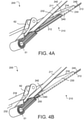
- each draw strap 240 has a first end 244 ( FIGS. 3A and 3B ) that is coupled to a respective riser above the curtain 230 and a second end 242 ( FIGS. 2B , 4A, and 4B ) that is coupled to the moveable portion (e.g., the bottom edge 232) of the curtain 230.
- the parachute riser assembly 200 further includes respective links 250 affixed to the left riser 212 and the right riser 222 proximate the attachment point of the harness 50.
- the links 250 may function as pulleys through which the draw straps 240 are configured to move in response to tensioning the risers during parachute deployment.
- each draw strap 240 may extend through and bend substantially 180 degrees about one of the links 250 ( FIG. 2B shows this very clearly).
- a first length of the risers 212, 222, as measured between the respective links 250 and the first end 244 of the draw straps 240, is greater than a second length of the respective draw straps 240, also as measured between the respective links 250 and the first end 244 of the draw straps. That is, with the curtain in the furled state, the risers 212, 222 may include loops 215 of excess material that contribute to the risers 212, 222 having a greater length between the two reference points (the respective links 250 and the first end 244 of the respective draw straps 240).
- loops 215 of excess length of the risers 212, 222 may become tensioned during parachute deployment, and as the slack of these loops 215 is taken up, the second end 242 of each draw strap 240, which is redirected around the link 250 and is attached to the bottom edge 232 of the curtain 230, is pulled down towards the harness, thereby causing the curtain 230 to unfurl or expand.
- the second length of the respective draw straps 240 (i.e., the length of the draw straps between the links 250 and the first ends 244 thereof) is increased as the draw strap 240 pulls on its second end 242 to meet the now fully taught first length of the risers 212, 222.
- the second end 242 of the respective draw straps 240 is thus pulled down towards the harness 50, thereby transitioning the curtain 230 to the unfurled state and substantially equalizing the first length and the second length.
- any of the method or process descriptions may be executed in any order and are not necessarily limited to the order presented.
- any reference to singular includes plural embodiments, and any reference to more than one component or step may include a singular embodiment or step.
- Elements and steps in the figures are illustrated for simplicity and clarity and have not necessarily been rendered according to any particular sequence. For example, steps that may be performed concurrently or in different order are illustrated in the figures to help to improve understanding of embodiments of the present disclosure.
- any reference to attached, fixed, connected or the like may include permanent, removable, temporary, partial, full and/or any other possible attachment option. Additionally, any reference to without contact (or similar phrases) may also include reduced contact or minimal contact.
- certain terms may be used such as “up,” “down,” “upper,” “lower,” “horizontal,” “vertical,” “left,” “right,” and the like. These terms are used, where applicable, to provide some clarity of description when dealing with relative relationships. But, these terms are not intended to imply absolute relationships, positions, and/or orientations. For example, with respect to an object, an "upper” surface can become a “lower” surface simply by turning the object over. Nevertheless, it is still the same object. Surface shading lines may be used throughout the figures to denote different parts or areas but not necessarily to denote the same or different materials. In some cases, reference coordinates may be specific to each figure.
- first, second, etc. are used herein merely as labels, and are not intended to impose ordinal, positional, or hierarchical requirements on the items to which these terms refer. Moreover, reference to, e.g., a “second” item does not require or preclude the existence of, e.g., a "first” or lower-numbered item, and/or, e.g., a "third" or higher-numbered item.
- references to "one embodiment”, “an embodiment”, “various embodiments”, etc. indicate that the embodiment described may include a particular feature, structure, or characteristic, but every embodiment may not necessarily include the particular feature, structure, or characteristic. Moreover, such phrases are not necessarily referring to the same embodiment. Further, when a particular feature, structure, or characteristic is described in connection with an embodiment, it is submitted that it is within the knowledge of one skilled in the art to affect such feature, structure, or characteristic in connection with other embodiments whether or not explicitly described. After reading the description, it will be apparent to one skilled in the relevant art(s) how to implement the disclosure in alternative embodiments.
Landscapes
- Engineering & Computer Science (AREA)
- Aviation & Aerospace Engineering (AREA)
- Curtains And Furnishings For Windows Or Doors (AREA)
Abstract
A parachute riser assembly for a parachute comprises a left riser (210), a right riser (220), and a curtain (230). The left riser is configured to extend from a canopy and is configured to be coupled to a left attachment point of a harness (50) worn by a user, according to various embodiments. Similarly, the right riser is configured to extend from the canopy and is configured to be coupled to a right attachment point of the harness, according to various embodiments. The curtain may be coupled to and may extend between the left riser and the right riser. In various embodiments, a portion of the curtain is configured to move along the left riser and the right riser from a furled state to an unfurled state in response to tensioning the left riser and the right riser.
Description
- The present disclosure relates to parachute riser assemblies, and in particular to providing neck support to parachute users in order to prevent neck hyperextension.
- Various aircraft include one or more ejection seats configured to eject a pilot or other occupant from the aircraft during an emergency. When a pilot or other occupant ejects from an aircraft, the subsequent separation of the pilot from the ejection seat often results in the pilot experiencing neck hyperextensions in response to rapid tensioning of the parachute risers. This problem may be exacerbated by the fact that the weight of a pilot's helmet has been increasing as more sophisticated equipment and components are integrated and incorporated with the pilot's helmet (e.g., helmet mounted display components, etc.).
- In various embodiments, the present disclosure provides a parachute riser assembly for a parachute. The parachute riser assembly may include a left riser, a right riser, and a curtain. The left riser is configured to extend from a canopy and is configured to be coupled to a left attachment point of a harness worn by a user, according to various embodiments. Similarly, the right riser is configured to extend from the canopy and is configured to be coupled to a right attachment point of the harness, according to various embodiments. The curtain may be coupled to and may extend between the left riser and the right riser. In various embodiments, a portion of the curtain is configured to move along the left riser and the right riser from a furled state to an unfurled state in response to tensioning the left riser and the right riser.
- In various embodiments, the curtain comprises a top edge and a bottom edge, wherein the bottom edge is the portion of the curtain that is configured to move along the left riser and the right riser such that the bottom edge moves down towards the harness along the left riser and the right riser in response to tensioning the left riser and the right riser via deployment of the parachute. In various embodiments, the top edge of the curtain is non-movably coupled to the left riser and the right riser such that the top edge is prevented from moving relative to the left riser and the right riser. In various embodiments, at least the bottom edge of the curtain comprises a sleeve structure that envelopes respective sections of the left riser and the right riser such that the sleeve structure enables the bottom edge of the curtain to be slidably coupled to the left riser and the right riser to allow the bottom edge of the curtain to slide along the left riser and the right riser towards the harness in response to deployment of the parachute.
- In various embodiments, the parachute riser assembly further includes respective draw straps extending along the left riser and the right riser, wherein each draw strap of the respective draw straps comprises a first end coupled to a respective riser and a second end directly coupled to the portion of the curtain. In various embodiments, the parachute riser assembly further includes respective links affixed to the left riser and the right riser proximate the harness, wherein each draw strap of the respective draw straps extends through and bends substantially 180 degrees about one link of the respective links. In the furled state a first length of the left riser and the right riser, as measured between the respective links and the first end of the respective draw straps, is greater than a second length of the respective draw straps, also as measured between the respective links and the first end of the respective draw straps, according to various embodiments. In response to tensioning the left riser and the right riser, the second length of the respective draw straps is increased as the second end of the respective draw straps is pulled down towards the harness, thereby transitioning the curtain to the unfurled state and substantially equalizing the first length and the second length, according to various embodiments.
- In various embodiments, a shape of a bottom edge of the curtain extending between the left riser and the right riser in the unfurled state is arcuate. In various embodiments, the left riser and the right riser are rear risers. In various embodiments, the parachute riser assembly further includes respective draw straps extending along the left riser and the right riser, wherein each draw strap of the respective draw straps comprises a first end coupled to a respective riser and a second end directly coupled to the portion of the curtain.
- Also disclosed herein, according to various embodiments, is a parachute that includes a canopy, a left riser, a right riser, a curtain, and respective draw straps. The left riser may extend from the canopy and may be configured to be coupled to a left attachment point of a harness worn by a user. Similarly, the right riser may extend from the canopy and may be configured to be coupled to a right attachment point of the harness. The curtain may be coupled to and may extend between the left riser and the right riser. The respective draw straps may extend along the left riser and the right riser, wherein each draw strap of the respective draw straps comprises a first end coupled to a respective riser and a second end directly coupled to a portion of the curtain. In various embodiments, the portion of the curtain is configured to move along the left riser and the right riser from a furled state to an unfurled state in response to tensioning the left riser and the right riser.
- In various embodiments, the parachute further includes respective links affixed to the left riser and the right riser proximate the harness, wherein each draw strap of the respective draw straps extends through and bends substantially 180 degrees about one link of the respective links. In the furled state a first length of the left riser and the right riser, as measured between the respective links and the first end of the respective draw straps, is greater than a second length of the respective draw straps, also as measured between the respective links and the first end of the respective draw straps. In various embodiments, in response to tensioning the left riser and the right riser, the second length of the respective draw straps is increased as the second end of the respective draw straps is pulled down towards the harness, thereby transitioning the curtain to the unfurled state and substantially equalizing the first length and the second length.
- The forgoing features and elements may be combined in various combinations without exclusivity, unless expressly indicated herein otherwise. These features and elements as well as the operation of the disclosed embodiments will become more apparent in light of the following description and accompanying drawings.
-
-
FIG. 1 is a schematic view of an aircraft ejection event, in accordance with various embodiments; -
FIG. 2A is a perspective view of a user seated in an aircraft ejection seat with a parachute riser assembly coupled to the user's harness, in accordance with various embodiments; -
FIG. 2B is an enlarged perspective view of the parachute riser assembly ofFIG. 2A , in accordance with various embodiments; -
FIG. 3A is a perspective view of a parachute riser assembly with a curtain in a furled state, in accordance with various embodiments; -
FIG. 3B is a perspective view of a parachute riser assembly with a curtain in an unfurled state, in accordance with various embodiments; -
FIG. 4A is a perspective view of a parachute riser assembly with a curtain in a furled state, in accordance with various embodiments; and -
FIG. 4B is a perspective view of a parachute riser assembly with a curtain in an unfurled state, in accordance with various embodiments. - The subject matter of the present disclosure is particularly pointed out and distinctly claimed in the concluding portion of the specification. A more complete understanding of the present disclosure, however, may best be obtained by referring to the detailed description and claims when considered in connection with the drawing figures.
- The detailed description of exemplary embodiments herein makes reference to the accompanying drawings, which show exemplary embodiments by way of illustration. While these exemplary embodiments are described in sufficient detail to enable those skilled in the art to practice the disclosure, it should be understood that other embodiments may be realized and that logical changes and adaptations in design and construction may be made in accordance with this disclosure and the teachings herein without departing from the scope of the invention as defined by the claims. Thus, the detailed description herein is presented for purposes of illustration only and not of limitation.
- Disclosed herein, according to various embodiments, is a parachute riser assembly configured to support the head and/or neck of a parachute user during parachute deployment. As described in greater detail below, the parachute riser assembly generally includes a curtain that transitions from a furled state to an unfurled state in response to tensioning the risers of the parachute (e.g., in response to parachute deployment), according to various embodiments. Although numerous details and examples are included herein pertaining to utilizing these concepts in conjunction with aircraft ejection systems, the present disclosure is not necessarily so limited, and thus aspects of the disclosed embodiments may be adapted for use in a variety of other parachute-related industries (e.g., non-ejection situations, such as skydiving, base jumping, etc.). As such, numerous applications of the present disclosure may be realized.
-
FIG. 1 is a schematic view of an aircraft ejection event, in accordance with various embodiments.FIG. 1 illustrates anaircraft ejection system 100, in accordance with various embodiments. Theaircraft ejection system 100 may be installed in anaircraft 102 to safely expel anejection seat 106 and auser 110 of theejection seat 106 from acockpit 104 of theaircraft 102. Theejection seat 106 may be urged from thecockpit 104 by apropulsion system 108. Theaircraft ejection system 100 may include aparachute 116. In various embodiments, prior to deployment of theparachute 116, a portion of theparachute 116 may be stored within theejection seat 106. - In various embodiments, and with reference to
FIG. 2A , aparachute riser assembly 200 is provided. Generally, theparachute riser assembly 200 is configured to extend from the canopy of a parachute 116 (which may be stored in the ejection seat 106) to aharness 50 worn by the user 110 (which may be a pilot, a crewperson, or other parachute user), according to various embodiments. Also shown inFIG. 2A , according to various embodiments, are inertialreal straps 64 androller fittings 62. Theroller fittings 62 are coupled to theharness 50 and the inertialreal straps 64 extend from theroller fittings 62 to theseat 106 in order to secure theuser 110 to theseat 106. The inertialreal straps 64 are configured to be released during seat-user separation after ejection.FIGS. 2B ,3A ,3B ,4A, and 4C show theroller fittings 62, but the inertialreal straps 64 are purposefully omitted from these figures in order to avoid obscuring the clarity of the depiction of theparachute riser assembly 200. - In various embodiments, and with reference to
FIG. 2B , an enlarged view of theparachute riser assembly 200 is provided. Theparachute riser assembly 200 generally includes one or moreleft risers 210 and one or moreright risers 220 that extend from the canopy to anattachment point 51 of theharness 50 worn by theuser 110, according to various embodiments. The one or moreleft risers 210 may include a leftforward riser 211 and a leftrear riser 212, while the one or moreright risers 220 may include a rightforward riser 221 and a rightrear riser 222. Theparachute riser assembly 200 may include acurtain 230 coupled to and between the leftrear riser 212 and the rightrear riser 222. As introduced above, thecurtain 230 is generally configured to support thehead 111 and/orneck 112 of theuser 110 during deployment of the parachute, according to various embodiments. That is, during parachute deployment with conventional risers, the head of the parachute user would be pushed back between the risers in response to the deployment force of the parachute. With thecurtain 230 in place between the risers, the rearward movement ofhead 111 and/orneck 112 of theuser 110 is prevented (or at least mitigated) by the presence of thecurtain 230. - In various embodiments the
curtain 230 is coupled between the leftrear riser 212 and the right rear riser 222 (as opposed to the corresponding forward risers, which would result in thehead 111 and/orneck 112 of theuser 110 being pushed to far forward or potentially covering the face of the user 110). Accordingly, the terms "left riser" and "right riser" as used below and in the claims refer to the respectiverear risers attachment point 51 to which theparachute riser assembly 200 is coupled is forward of the user's shoulders. That is, theattachment point 51 may be proximate the chest of the user. - In various embodiments, and with continued reference to
FIG. 2B , thecurtain 230 comprises abottom edge 232 and a top edge 234 (FIG 3A ). The terms "bottom," "down," "top," and "up" refer to relative positions of various components based on a standard orientation of thecurtain 230 with the parachute in a deployed state, with theriser assembly 200 extending upward from theattachment point 51 to the canopy above theuser 110. In various embodiments, thecurtain 230 comprises a portion that is configured to move (e.g., slide) along therisers FIGS. 3A and 3B . With thecurtain 230 having at least a portion thereof that can move along therisers curtain 230 can transition from a collapsed/stowed configuration (i.e., the furled state) to an expanded/deployed configuration (i.e., the unfurled state). In various embodiments, theparachute riser assembly 200 further includes respective draw straps 240 andrespective links 250 to facilitate the expansion of thecurtain 230, as explained in greater detail below starting with reference toFIGS. 3A and 3B . - In various embodiments, and with reference to
FIGS. 3A and 3B , the moveable portion of thecurtain 230 is configured to move down towards the user. According to various embodiments, one of the benefits of having thecurtain 230 comprise this downward-expanding configuration is that in the furled state, thebottom edge 232 of thecurtain 230 remains a distance away from theneck 112 of the user (e.g., seeFIG. 2B , with thebottom edge 232 of the curtain not being in direct contact with theneck 112 of the user). Such a configuration may provide various comfort and/or safety benefits to the user. For example, if a parachute assembly were to be implemented with a non-expanding neck support panel between the risers, the support panel would likely be in constant contact with the back of the neck of the user, which would be an uncomfortable and/or distracting nuisance to the user (e.g., a pilot) and could potentially cause harm/damage to the user, or otherwise create a hazardous situation. - In various embodiments, and with continued reference to
FIGS. 3A and 3B , movement of the portion (e.g., the bottom edge 232) of thecurtain 230 is configured to automatically occur in response to tensioning theleft riser 212 and theright riser 222. Said differently, in response to therisers curtain 230 may automatically transition from the furled state (FIG. 3A ) to the unfurled state (FIG. 3B ). In various embodiments, thecurtain 230 may have a tapered, fan-like shape in the unfurled state. A shape of thebottom edge 232 of thecurtain 230 may be arcuate, thus further improving the comfort that the user experiences with the curtain in the furled state (stowed configuration) and also potentially improving the ergonomics of thecurtain 230 relative to the user's neck in the unfurled state (deployed configuration). - In various embodiments, the
top edge 234 of the curtain is non-movably coupled (e.g., permanently affixed) to theleft riser 212 and theright riser 222 such that thetop edge 234 is prevented from moving relative to theleft riser 212 and theright riser 222. In various embodiments, at least thebottom edge 232 of thecurtain 230 comprises a sleeve structure that envelopes respective sections of theleft riser 212 and theright riser 222 such that the sleeve structure enables therisers curtain 230 may allow for thebottom edge 232 of thecurtain 230, which is positioned around therisers risers harness 50. This sliding movement may be facilitated by the draw straps 240 and thelinks 250, as described in greater detail below. - In various embodiments, and with reference to
FIGS. 3A and 3B , theparachute riser assembly 200 includes draw straps 240 that respectively extend along at least a section/segment of theleft riser 212 and theright riser 222. The draw straps 240, according to various embodiments, may be generally configured to facilitate the automatic transition of the curtain from the furled state to the unfurled state. For example, according to various embodiments, eachdraw strap 240 has a first end 244 (FIGS. 3A and 3B ) that is coupled to a respective riser above thecurtain 230 and a second end 242 (FIGS. 2B ,4A, and 4B ) that is coupled to the moveable portion (e.g., the bottom edge 232) of thecurtain 230. - In various embodiments, the
parachute riser assembly 200 further includesrespective links 250 affixed to theleft riser 212 and theright riser 222 proximate the attachment point of theharness 50. Thelinks 250 may function as pulleys through which the draw straps 240 are configured to move in response to tensioning the risers during parachute deployment. For example, eachdraw strap 240 may extend through and bend substantially 180 degrees about one of the links 250 (FIG. 2B shows this very clearly). Returning to referenceFIGS. 3A and 3B , a first length of therisers respective links 250 and thefirst end 244 of the draw straps 240, is greater than a second length of the respective draw straps 240, also as measured between therespective links 250 and thefirst end 244 of the draw straps. That is, with the curtain in the furled state, therisers loops 215 of excess material that contribute to therisers respective links 250 and thefirst end 244 of the respective draw straps 240). Theseloops 215 of excess length of therisers loops 215 is taken up, thesecond end 242 of eachdraw strap 240, which is redirected around thelink 250 and is attached to thebottom edge 232 of thecurtain 230, is pulled down towards the harness, thereby causing thecurtain 230 to unfurl or expand. That is, in response to tensioning theleft riser 212 and theright riser 222, the second length of the respective draw straps 240 (i.e., the length of the draw straps between thelinks 250 and the first ends 244 thereof) is increased as thedraw strap 240 pulls on itssecond end 242 to meet the now fully taught first length of therisers second end 242 of the respective draw straps 240 is thus pulled down towards theharness 50, thereby transitioning thecurtain 230 to the unfurled state and substantially equalizing the first length and the second length. - Benefits, other advantages, and solutions to problems have been described herein with regard to specific embodiments. Furthermore, the connecting lines shown in the various figures contained herein are intended to represent exemplary functional relationships and/or physical couplings between the various elements. It should be noted that many alternative or additional functional relationships or physical connections may be present in a practical system. However, the benefits, advantages, solutions to problems, and any elements that may cause any benefit, advantage, or solution to occur or become more pronounced are not to be construed as critical, required, or essential features or elements of the disclosure.
- The scope of the disclosure is accordingly to be limited by nothing other than the appended claims, in which reference to an element in the singular is not intended to mean "one and only one" unless explicitly so stated, but rather "one or more." It is to be understood that unless specifically stated otherwise, references to "a," "an," and/or "the" may include one or more than one and that reference to an item in the singular may also include the item in the plural. All ranges and ratio limits disclosed herein may be combined.
- Moreover, where a phrase similar to "at least one of A, B, or C" is used in the claims, it is intended that the phrase be interpreted to mean that A alone may be present in an embodiment, B alone may be present in an embodiment, C alone may be present in an embodiment, or that any combination of the elements A, B and C may be present in a single embodiment; for example, A and B, A and C, B and C, or A and B and C. Different cross-hatching is used throughout the figures to denote different parts but not necessarily to denote the same or different materials.
- The steps recited in any of the method or process descriptions may be executed in any order and are not necessarily limited to the order presented. Furthermore, any reference to singular includes plural embodiments, and any reference to more than one component or step may include a singular embodiment or step. Elements and steps in the figures are illustrated for simplicity and clarity and have not necessarily been rendered according to any particular sequence. For example, steps that may be performed concurrently or in different order are illustrated in the figures to help to improve understanding of embodiments of the present disclosure.
- Any reference to attached, fixed, connected or the like may include permanent, removable, temporary, partial, full and/or any other possible attachment option. Additionally, any reference to without contact (or similar phrases) may also include reduced contact or minimal contact. In the above description, certain terms may be used such as "up," "down," "upper," "lower," "horizontal," "vertical," "left," "right," and the like. These terms are used, where applicable, to provide some clarity of description when dealing with relative relationships. But, these terms are not intended to imply absolute relationships, positions, and/or orientations. For example, with respect to an object, an "upper" surface can become a "lower" surface simply by turning the object over. Nevertheless, it is still the same object. Surface shading lines may be used throughout the figures to denote different parts or areas but not necessarily to denote the same or different materials. In some cases, reference coordinates may be specific to each figure.
- Unless otherwise indicated, the terms "first," "second," etc. are used herein merely as labels, and are not intended to impose ordinal, positional, or hierarchical requirements on the items to which these terms refer. Moreover, reference to, e.g., a "second" item does not require or preclude the existence of, e.g., a "first" or lower-numbered item, and/or, e.g., a "third" or higher-numbered item.
- Systems, methods and apparatus are provided herein. In the detailed description herein, references to "one embodiment", "an embodiment", "various embodiments", etc., indicate that the embodiment described may include a particular feature, structure, or characteristic, but every embodiment may not necessarily include the particular feature, structure, or characteristic. Moreover, such phrases are not necessarily referring to the same embodiment. Further, when a particular feature, structure, or characteristic is described in connection with an embodiment, it is submitted that it is within the knowledge of one skilled in the art to affect such feature, structure, or characteristic in connection with other embodiments whether or not explicitly described. After reading the description, it will be apparent to one skilled in the relevant art(s) how to implement the disclosure in alternative embodiments.
Claims (11)
- A parachute riser assembly for a parachute, the parachute riser assembly comprising:a left riser (210) configured to extend from a canopy and configured to be coupled to a left attachment point (51) of a harness (50) worn by a user (110);a right riser (220) configured to extend from the canopy and configured to be coupled to a right attachment point (51) of the harness; anda curtain (230) coupled to and extending between the left riser and the right riser;wherein a portion of the curtain is configured to move along the left riser and the right riser from a furled state to an unfurled state in response to tensioning the left riser and the right riser.
- The parachute riser assembly of claim 1, wherein the curtain comprises a top edge (234) and a bottom edge (232), wherein the bottom edge is the portion of the curtain that is configured to move along the left riser and the right riser such that the bottom edge moves down towards the harness along the left riser and the right riser in response to tensioning the left riser and the right riser via deployment of the parachute.
- The parachute riser assembly of claim 2, wherein the top edge (234) of the curtain is non-movably coupled to the left riser and the right riser such that the top edge is prevented from moving relative to the left riser and the right riser.
- The parachute riser assembly of claim 3, wherein at least the bottom edge (232) of the curtain comprises a sleeve structure that envelopes respective sections of the left riser and the right riser such that the sleeve structure enables the bottom edge of the curtain to be slidably coupled to the left riser and the right riser to allow the bottom edge of the curtain to slide along the left riser and the right riser towards the harness in response to deployment of the parachute.
- The parachute riser assembly of any preceding claim, further comprising respective draw straps (240) extending along the left riser and the right riser, wherein each draw strap of the respective draw straps comprises a first end (244) coupled to a respective riser and a second end (242) directly coupled to the portion of the curtain.
- The parachute riser assembly of claim 5, further comprising respective links (250) affixed to the left riser and the right riser proximate the harness, wherein each draw strap of the respective draw straps extends through and bends substantially 180 degrees about one link of the respective links.
- The parachute riser assembly of claim 6, wherein in the furled state a first length of the left riser and the right riser, as measured between the respective links and the first end of the respective draw straps, is greater than a second length of the respective draw straps, also as measured between the respective links and the first end of the respective draw straps.
- The parachute riser assembly of claim 7, wherein, in response to tensioning the left riser and the right riser, the second length of the respective draw straps is increased as the second end of the respective draw straps is pulled down towards the harness, thereby transitioning the curtain to the unfurled state and substantially equalizing the first length and the second length.
- The parachute riser assembly of any preceding claim, wherein a shape of a bottom edge of the curtain extending between the left riser and the right riser in the unfurled state is arcuate.
- The parachute riser assembly of any preceding claim, wherein the left riser and the right riser are rear risers (212, 222).
- A parachute comprising:a canopy;a parachute riser assembly as claimed in claim 5 or any claim dependent thereon,the left riser and the right riser extending from the canopy.
Applications Claiming Priority (1)
| Application Number | Priority Date | Filing Date | Title |
|---|---|---|---|
| US17/020,604 US11279493B1 (en) | 2020-09-14 | 2020-09-14 | Parachute riser assembly |
Publications (1)
| Publication Number | Publication Date |
|---|---|
| EP3967604A1 true EP3967604A1 (en) | 2022-03-16 |
Family
ID=78008102
Family Applications (1)
| Application Number | Title | Priority Date | Filing Date |
|---|---|---|---|
| EP21196614.8A Withdrawn EP3967604A1 (en) | 2020-09-14 | 2021-09-14 | Parachute riser assembly |
Country Status (2)
| Country | Link |
|---|---|
| US (1) | US11279493B1 (en) |
| EP (1) | EP3967604A1 (en) |
Citations (4)
| Publication number | Priority date | Publication date | Assignee | Title |
|---|---|---|---|---|
| EP3156332A2 (en) * | 2015-10-16 | 2017-04-19 | Martin-Baker Aircraft Co. Ltd. | A parachute |
| US20200094972A1 (en) * | 2018-09-21 | 2020-03-26 | Goodrich Corporation | Head restraint for parachute assemblies |
| US20200094973A1 (en) * | 2018-09-21 | 2020-03-26 | Goodrich Corporation | Inflatable head restraint for parachutes |
| US20200094974A1 (en) * | 2018-09-21 | 2020-03-26 | Goodrich Corporation | Seat back head restrain for parachute assemblies |
Family Cites Families (2)
| Publication number | Priority date | Publication date | Assignee | Title |
|---|---|---|---|---|
| US4850554A (en) | 1987-01-27 | 1989-07-25 | Strong Edward T | Stabilizing parachute harness |
| US10946970B2 (en) * | 2018-09-21 | 2021-03-16 | Goodrich Corporation | Systems for removal of parachute assembly head restraints |
-
2020
- 2020-09-14 US US17/020,604 patent/US11279493B1/en not_active Expired - Fee Related
-
2021
- 2021-09-14 EP EP21196614.8A patent/EP3967604A1/en not_active Withdrawn
Patent Citations (4)
| Publication number | Priority date | Publication date | Assignee | Title |
|---|---|---|---|---|
| EP3156332A2 (en) * | 2015-10-16 | 2017-04-19 | Martin-Baker Aircraft Co. Ltd. | A parachute |
| US20200094972A1 (en) * | 2018-09-21 | 2020-03-26 | Goodrich Corporation | Head restraint for parachute assemblies |
| US20200094973A1 (en) * | 2018-09-21 | 2020-03-26 | Goodrich Corporation | Inflatable head restraint for parachutes |
| US20200094974A1 (en) * | 2018-09-21 | 2020-03-26 | Goodrich Corporation | Seat back head restrain for parachute assemblies |
Also Published As
| Publication number | Publication date |
|---|---|
| US20220081120A1 (en) | 2022-03-17 |
| US11279493B1 (en) | 2022-03-22 |
Similar Documents
| Publication | Publication Date | Title |
|---|---|---|
| US10414503B2 (en) | Components for enhancement of a low profile crew attendant seat | |
| US11046444B2 (en) | Inflatable head restraint for parachutes | |
| US11235883B2 (en) | Evacuation slide restraint | |
| EP3227183B1 (en) | Tray table assembly | |
| US11021256B2 (en) | Seat back head restrain for parachute assemblies | |
| CN103842253B (en) | Aircraft cockpit, display device and hood for cockpit, and aircraft | |
| US11027851B2 (en) | Head restraint for parachute assemblies | |
| EP3446978B1 (en) | Contoured stowable seat | |
| US20110062283A1 (en) | Device for delimiting a crew rest compartment and method for implementing such a device | |
| US11708167B2 (en) | Multipurpose readiness indicator for off-wing slide raft | |
| EP3960628B1 (en) | Aircraft seat cover attachment system | |
| US10556698B2 (en) | Asymmetric yoke | |
| US20170106987A1 (en) | Parachute | |
| US20060061202A1 (en) | Adjustable seat belt guide assembly | |
| US11279493B1 (en) | Parachute riser assembly | |
| US10000292B1 (en) | Multipurpose lane divider for evacuation slide | |
| US11136098B2 (en) | Integrated lifeline and geometric restraint | |
| EP4321435B1 (en) | Deployable sleep support system for seated passengers | |
| US12351086B2 (en) | Safety belt adjustment mechanism and safety seat using the same | |
| US11465761B2 (en) | Neck protection system for parachute assemblies | |
| EP3816051A1 (en) | Integrated truss restraint | |
| US20180319507A1 (en) | Evacuation slide connector | |
| US10661904B1 (en) | Stowable harness fan assembly for a low-back divan | |
| US12371166B2 (en) | Deployable sleep support system for seated passengers | |
| CN110877556B (en) | Lateral head support for a vehicle passenger seat |
Legal Events
| Date | Code | Title | Description |
|---|---|---|---|
| PUAI | Public reference made under article 153(3) epc to a published international application that has entered the european phase |
Free format text: ORIGINAL CODE: 0009012 |
|
| STAA | Information on the status of an ep patent application or granted ep patent |
Free format text: STATUS: THE APPLICATION HAS BEEN PUBLISHED |
|
| AK | Designated contracting states |
Kind code of ref document: A1 Designated state(s): AL AT BE BG CH CY CZ DE DK EE ES FI FR GB GR HR HU IE IS IT LI LT LU LV MC MK MT NL NO PL PT RO RS SE SI SK SM TR |
|
| STAA | Information on the status of an ep patent application or granted ep patent |
Free format text: STATUS: THE APPLICATION IS DEEMED TO BE WITHDRAWN |
|
| 18D | Application deemed to be withdrawn |
Effective date: 20220917 |