EP3967586A1 - Leaning vehicle equipped with autonomous emergency braking (aeb) control device - Google Patents
Leaning vehicle equipped with autonomous emergency braking (aeb) control device Download PDFInfo
- Publication number
- EP3967586A1 EP3967586A1 EP20805495.7A EP20805495A EP3967586A1 EP 3967586 A1 EP3967586 A1 EP 3967586A1 EP 20805495 A EP20805495 A EP 20805495A EP 3967586 A1 EP3967586 A1 EP 3967586A1
- Authority
- EP
- European Patent Office
- Prior art keywords
- braking force
- wheel braking
- rear wheel
- front wheel
- state
- Prior art date
- Legal status (The legal status is an assumption and is not a legal conclusion. Google has not performed a legal analysis and makes no representation as to the accuracy of the status listed.)
- Granted
Links
Images


Classifications
-
- B—PERFORMING OPERATIONS; TRANSPORTING
- B60—VEHICLES IN GENERAL
- B60T—VEHICLE BRAKE CONTROL SYSTEMS OR PARTS THEREOF; BRAKE CONTROL SYSTEMS OR PARTS THEREOF, IN GENERAL; ARRANGEMENT OF BRAKING ELEMENTS ON VEHICLES IN GENERAL; PORTABLE DEVICES FOR PREVENTING UNWANTED MOVEMENT OF VEHICLES; VEHICLE MODIFICATIONS TO FACILITATE COOLING OF BRAKES
- B60T7/00—Brake-action initiating means
- B60T7/12—Brake-action initiating means for automatic initiation; for initiation not subject to will of driver or passenger
- B60T7/22—Brake-action initiating means for automatic initiation; for initiation not subject to will of driver or passenger initiated by contact of vehicle, e.g. bumper, with an external object, e.g. another vehicle, or by means of contactless obstacle detectors mounted on the vehicle
-
- B—PERFORMING OPERATIONS; TRANSPORTING
- B60—VEHICLES IN GENERAL
- B60T—VEHICLE BRAKE CONTROL SYSTEMS OR PARTS THEREOF; BRAKE CONTROL SYSTEMS OR PARTS THEREOF, IN GENERAL; ARRANGEMENT OF BRAKING ELEMENTS ON VEHICLES IN GENERAL; PORTABLE DEVICES FOR PREVENTING UNWANTED MOVEMENT OF VEHICLES; VEHICLE MODIFICATIONS TO FACILITATE COOLING OF BRAKES
- B60T8/00—Arrangements for adjusting wheel-braking force to meet varying vehicular or ground-surface conditions, e.g. limiting or varying distribution of braking force
- B60T8/17—Using electrical or electronic regulation means to control braking
- B60T8/1701—Braking or traction control means specially adapted for particular types of vehicles
- B60T8/1706—Braking or traction control means specially adapted for particular types of vehicles for single-track vehicles, e.g. motorcycles
-
- B—PERFORMING OPERATIONS; TRANSPORTING
- B60—VEHICLES IN GENERAL
- B60T—VEHICLE BRAKE CONTROL SYSTEMS OR PARTS THEREOF; BRAKE CONTROL SYSTEMS OR PARTS THEREOF, IN GENERAL; ARRANGEMENT OF BRAKING ELEMENTS ON VEHICLES IN GENERAL; PORTABLE DEVICES FOR PREVENTING UNWANTED MOVEMENT OF VEHICLES; VEHICLE MODIFICATIONS TO FACILITATE COOLING OF BRAKES
- B60T8/00—Arrangements for adjusting wheel-braking force to meet varying vehicular or ground-surface conditions, e.g. limiting or varying distribution of braking force
- B60T8/17—Using electrical or electronic regulation means to control braking
- B60T8/176—Brake regulation specially adapted to prevent excessive wheel slip during vehicle deceleration, e.g. ABS
- B60T8/1766—Proportioning of brake forces according to vehicle axle loads, e.g. front to rear of vehicle
-
- B—PERFORMING OPERATIONS; TRANSPORTING
- B60—VEHICLES IN GENERAL
- B60T—VEHICLE BRAKE CONTROL SYSTEMS OR PARTS THEREOF; BRAKE CONTROL SYSTEMS OR PARTS THEREOF, IN GENERAL; ARRANGEMENT OF BRAKING ELEMENTS ON VEHICLES IN GENERAL; PORTABLE DEVICES FOR PREVENTING UNWANTED MOVEMENT OF VEHICLES; VEHICLE MODIFICATIONS TO FACILITATE COOLING OF BRAKES
- B60T8/00—Arrangements for adjusting wheel-braking force to meet varying vehicular or ground-surface conditions, e.g. limiting or varying distribution of braking force
- B60T8/26—Arrangements for adjusting wheel-braking force to meet varying vehicular or ground-surface conditions, e.g. limiting or varying distribution of braking force characterised by producing differential braking between front and rear wheels
- B60T8/261—Arrangements for adjusting wheel-braking force to meet varying vehicular or ground-surface conditions, e.g. limiting or varying distribution of braking force characterised by producing differential braking between front and rear wheels specially adapted for use in motorcycles
-
- B—PERFORMING OPERATIONS; TRANSPORTING
- B62—LAND VEHICLES FOR TRAVELLING OTHERWISE THAN ON RAILS
- B62L—BRAKES SPECIALLY ADAPTED FOR CYCLES
- B62L3/00—Brake-actuating mechanisms; Arrangements thereof
- B62L3/08—Mechanisms specially adapted for braking more than one wheel
-
- B—PERFORMING OPERATIONS; TRANSPORTING
- B62—LAND VEHICLES FOR TRAVELLING OTHERWISE THAN ON RAILS
- B62L—BRAKES SPECIALLY ADAPTED FOR CYCLES
- B62L5/00—Brakes, or actuating mechanisms therefor, controlled by back-pedalling
- B62L5/20—Brakes, or actuating mechanisms therefor, controlled by back-pedalling the brakes having adjustable braking power
-
- B—PERFORMING OPERATIONS; TRANSPORTING
- B60—VEHICLES IN GENERAL
- B60T—VEHICLE BRAKE CONTROL SYSTEMS OR PARTS THEREOF; BRAKE CONTROL SYSTEMS OR PARTS THEREOF, IN GENERAL; ARRANGEMENT OF BRAKING ELEMENTS ON VEHICLES IN GENERAL; PORTABLE DEVICES FOR PREVENTING UNWANTED MOVEMENT OF VEHICLES; VEHICLE MODIFICATIONS TO FACILITATE COOLING OF BRAKES
- B60T2201/00—Particular use of vehicle brake systems; Special systems using also the brakes; Special software modules within the brake system controller
- B60T2201/02—Active or adaptive cruise control system; Distance control
- B60T2201/022—Collision avoidance systems
Definitions
- the present teaching relates to a leaning vehicle including an AEB (Autonomous Emergency Braking) control device which is configured to automatically control braking force without requiring an operation of at least one of a front wheel brake operator or a rear wheel brake operator, based on a margin acquired based on the relationship between an obstacle and a host vehicle.
- AEB Automatic Emergency Braking
- Patent Literature 1 proposes a leaning vehicle including an AEB control device which is configured to automatically control braking force without requiring an operation of at least one of a front wheel brake operator or a rear wheel brake operator, based on a margin acquired based on the relationship between an obstacle and a host vehicle and corresponds to the obstacle.
- the leaning vehicle includes the front wheel brake operator and the rear wheel brake operator that are operated by a rider, and leans rightward in the vehicle left-right direction when turning right and leans leftward in the vehicle left-right direction when turning left.
- Patent Literature 1 Japanese Unexamined Patent Publication No. 2017-024644
- An object of the present teaching is to provide a leaning vehicle which includes a front wheel brake operator and a rear wheel brake operator that are operated by a rider, leans rightward in a vehicle left-right direction when turning right and leans leftward in the vehicle left-right direction when turning left, and includes an AEB control device configured to perform control different from known control schemes.
- the inventors of the present teaching diligently studied an assisting braking force automatically generated in a leaning vehicle including an AEB control device which is configured to automatically generate braking force without requiring an operation of at least one of a front wheel brake operator or a rear wheel brake operator, based on a margin acquired based on the relationship between an obstacle and a host vehicle, and found a novel control scheme.
- a leaning vehicle which includes a front wheel brake operator and a rear wheel brake operator that are operated by a rider and leans rightward in a vehicle left-right direction when turning right and leans leftward in the vehicle left-right direction when turning left
- braking force which is automatically generated based on a margin acquired based on the relationship between an obstacle and a host vehicle is controlled in consideration of the balance between a front wheel braking force and a rear wheel braking force relative to an ideal braking force distribution when one rider rides.
- the leaning vehicle includes the front wheel brake operator and the rear wheel brake operator.
- the rider may control the action of the leaning vehicle by adjusting the balance between the front wheel brake operator and the rear wheel brake operator.
- the present teaching is based on a technical idea that a braking force which is generated automatically is controlled in consideration of the balance between a front wheel braking force and a rear wheel braking force relative to an ideal braking force distribution when one rider rides.
- This technical idea is totally different from the technical idea of Patent Literature 1, i.e., an automatically-generated braking force is separated into a front wheel braking force and a rear wheel braking force, and a braking force is controlled with the use of the limits of front wheel braking force and rear wheel braking force, respectively.
- a leaning vehicle including an AEB control device of an embodiment of the present teaching has the following structures.
- a leaning vehicle comprises: a front wheel brake operator and a rear wheel brake operator that are operated by a rider; and an AEB (Autonomous Emergency Braking) control device which is mounted on a leaning vehicle body frame leaning rightward in a vehicle left-right direction when turning right and leaning leftward in the vehicle left-right direction when turning left and is configured to automatically control the front wheel braking force and the rear wheel braking force without requiring an operation of at least one of the front wheel brake operator or the rear wheel brake operator, based on a margin acquired based on the relationship between an obstacle and the leaning vehicle.
- the AEB control device controls the front wheel braking force and the rear wheel braking force that are automatically generated, so that the state transition of the front wheel braking force and the rear wheel braking force is a state transition 1 described below.
- State transition 1 Within a range excluding a range in which the rear wheel braking force is small as compared to an ideal braking force distribution when one rider rides, a state where the front wheel braking force and the rear wheel braking force are both zero transitions to a state of changing along positions where the front wheel braking force and the rear wheel braking force are both not zero.
- a leaning vehicle including an AEB control device of an embodiment of the present teaching may have the following structure.
- the AEB control device controls the front wheel braking force and the rear wheel braking force that are automatically generated, so that the state transition of the front wheel braking force and the rear wheel braking force is a state transition 2 described below.
- State transition 2 Within a range excluding a range in which the rear wheel braking force is small as compared to the ideal braking force distribution when one rider rides, a state where the front wheel braking force and the rear wheel braking force are both zero transitions to a state of departing from the ideal braking force distribution when one rider rides and a braking force distribution at which the front wheel braking force is zero.
- a leaning vehicle including an AEB control device of an embodiment of the present teaching may have the following structure.
- the AEB control device controls the front wheel braking force and the rear wheel braking force that are automatically generated, so that the state transition of the front wheel braking force and the rear wheel braking force is a state transition 3 described below.
- State transition 3 Within a range excluding a range in which the rear wheel braking force is small as compared to the ideal braking force distribution when one rider rides, a state of departing from the ideal braking force distribution when one rider rides transitions to a state of coming close to the ideal braking force distribution when one rider rides so that the total braking force which is the sum total of the front wheel braking force and the rear wheel braking force increases.
- a leaning vehicle including an AEB control device of an embodiment of the present teaching may have the following structure.
- the AEB control device controls the front wheel braking force and the rear wheel braking force that are automatically generated, so that the state transition of the front wheel braking force and the rear wheel braking force is a state transition 4 described below.
- State transition 4 Within a range excluding a range in which the rear wheel braking force is small as compared to the ideal braking force distribution when one rider rides, transition to a state of changing along the ideal braking force distribution when one rider rides so that the total braking force which is the sum total of the front wheel braking force and the rear wheel braking force increases occurs.
- a leaning vehicle including an AEB control device of an embodiment of the present teaching may have the following structure.
- the AEB control device controls the front wheel braking force and the rear wheel braking force that are automatically generated, so that the state transition of the front wheel braking force and the rear wheel braking force is a state transition 5 described below.
- State transition 5 Within a range excluding a range in which the rear wheel braking force is small as compared to the ideal braking force distribution when one rider rides, a state of changing along the ideal braking force distribution when one rider rides so that the total braking force increases transitions to a state of departing from the ideal braking force distribution when one rider rides.
- a leaning vehicle including an AEB control device of an embodiment of the present teaching may have the following structure.
- the AEB control device controls the front wheel braking force and the rear wheel braking force that are automatically generated, so that the state transition of the front wheel braking force and the rear wheel braking force is a state transition 6 described below.
- State transition 6 Within a range excluding a range in which the rear wheel braking force is small as compared to the ideal braking force distribution when one rider rides, a state where the total braking force which is the sum total of the front wheel braking force and the rear wheel braking force increases transitions to a state where the total braking force is maintained.
- the braking force which is automatically generated based on a margin acquired based on the relationship between an obstacle and a host vehicle can be controlled in consideration of the balance between the front wheel braking force and the rear wheel braking force relative to an ideal braking force distribution when one rider rides.
- the present teaching is based on a technical idea that the braking force which is generated automatically is controlled in consideration of the balance between the front wheel braking force and the rear wheel braking force relative to an ideal braking force distribution when one rider rides.
- This technical idea is totally different from the technical idea of Patent Literature 1, i.e., automatically-generated braking force is separated into front wheel braking force and rear wheel braking force, and the braking force is controlled with the use of the limit of each force.
- the present teaching is therefore able to provide a leaning vehicle which includes a front wheel brake operator and a rear wheel brake operator that are operated by a rider, leans rightward in a vehicle left-right direction when turning right and leans leftward in the vehicle left-right direction when turning left, and includes an AEB control device configured to perform a control different from known control schemes.
- the AEB control device may control the front wheel braking force and the rear wheel braking force that are automatically generated, so that the state transition of the front wheel braking force and the rear wheel braking force is a state transition 8 described below.
- State transition 8 Within a range excluding a range in which the rear wheel braking force is small as compared to the ideal braking force distribution when one rider rides on the leaning vehicle, transition to a state where the rear wheel braking force is increased and the front wheel braking force is decreased while the total braking force is maintained occurs.
- the AEB control device may control the front wheel braking force and the rear wheel braking force that are automatically generated, so that the state transition of the front wheel braking force and the rear wheel braking force is a state transition 9 described below.
- State transition 9 Within a range excluding a range in which the rear wheel braking force is small as compared to the ideal braking force distribution when one rider rides on the leaning vehicle, when the vehicle speed decreases either after the total braking force is increased or while the total braking force is being increased, transition to a state where the rear wheel braking force is increased and the front wheel braking force is decreased occurs.
- the AEB control device may control the front wheel braking force and the rear wheel braking force that are automatically generated, so that the state transition of the front wheel braking force and the rear wheel braking force is a state transition 10 described below.
- State transition 10 Within a range excluding a range in which the rear wheel braking force is small as compared to the ideal braking force distribution when one rider rides on the leaning vehicle, a state where the front wheel braking force and the rear wheel braking force are maintained transitions to a state where the rear wheel braking force increases whereas the front wheel braking force decreases.
- the AEB control device may control the front wheel braking force and the rear wheel braking force that are automatically generated, so that the state transition of the front wheel braking force and the rear wheel braking force is a state transition 11 described below.
- State transition 11 Within a range excluding a range in which the rear wheel braking force is small as compared to the ideal braking force distribution when one rider rides on the leaning vehicle, transition to a state where the front wheel braking force and the rear wheel braking force are maintained occurs.
- a state of changing along positions where the front wheel braking force and the rear wheel braking force are both not zero is a state where the front wheel braking force changes within a range excluding zero and the rear wheel braking force changes within a range excluding zero.
- the state excludes a state where the rear wheel braking force changes while the front wheel braking force remains at zero and a state where the front wheel braking force changes while the rear wheel braking force remains at zero.
- An ideal braking force distribution when one rider rides on the leaning vehicle in the present teaching and the embodiments is an ideal braking force distribution calculated with the assumption that the load on the leaning vehicle is only one rider who has a typical weight.
- the ideal braking force distribution when one rider rides on the leaning vehicle is calculated by a known method.
- the weight of the rider is, for example, 50kg. This weight of the rider is a relatively lightweight as compared to an average weight of Japanese people including women.
- the ideal braking force distribution when one rider rides on the leaning vehicle is a distribution of the front wheel braking force and the rear wheel braking force which is most efficient for generating deceleration (negative acceleration).
- Only one ideal braking force distribution when one rider rides is set for a single value of total braking force.
- only one ideal braking force against a front wheel and only one ideal braking force against a rear wheel are set for a single value of total braking force.
- Ideal braking force B f [N] against the front wheel and ideal braking force B r [N] against the rear wheel are calculated by the following mathematical expression, in accordance with a road surface ⁇ (coefficient of friction on a road).
- ⁇ m indicates a deceleration coefficient
- W[N] indicates vehicle weight
- W f0 [N] indicates a front wheel shared load at vehicle stop
- W r0 [N] indicates a rear wheel shared load at vehicle stop
- H[m] indicates ground height of the gravity center
- L[m] indicates the wheelbase.
- Examples of the dimensions include the vehicle weight, the distance in the vehicle front-rear direction between the gravity center and the grounding point of a front wheel, the distance in the vehicle front-rear direction between the gravity center and the grounding point of a rear wheel, and the ground height of the gravity center.
- B f ⁇ m ⁇ W f 0 + ⁇ m ⁇ H ⁇ W L
- B r ⁇ m ⁇ W r 0 ⁇ ⁇ m ⁇ H ⁇ W L
- a brake assist control device of the present teaching may control the braking force by utilizing the ideal braking force distribution when one rider rides according to the present teaching or an ideal braking force distribution when two occupants ride.
- the ideal braking force distribution when one rider rides will be simply referred to as the ideal braking force distribution.
- a state of coming close to the ideal braking force distribution when one rider rides in the present teaching and the embodiments includes a state of coming close to a position on the ideal braking force distribution when one rider rides from a position not on the ideal braking force distribution when one rider rides.
- the AEB control device controls at least one of the front wheel braking force or the rear wheel braking force so that the front wheel braking force and the rear wheel braking force come close to the ideal braking force distribution when one rider rides.
- the state of coming close to the ideal braking force distribution when one rider rides includes a state where the above-described control of causing the front wheel braking force and the rear wheel braking force to come close to the ideal braking force distribution has been done.
- the state of coming close to the ideal braking force distribution when one rider rides is a state of coming close to a position on the ideal braking force distribution when one rider rides from a position not on the ideal braking force distribution when one rider rides and reaching a position immediately before the ideal braking force distribution when one rider rides.
- the state of coming close to the ideal braking force distribution when one rider rides is a state of coming close to a position on the ideal braking force distribution when one rider rides from a position not on the ideal braking force distribution when one rider rides, going across the ideal braking force distribution when one rider rides, and reaching a position not on the ideal braking force distribution when one rider rides.
- a state of coming close to the ideal braking force distribution when two occupants ride is identical with the state of coming close to the ideal braking force distribution when one rider rides, except that one rider is replaced with two occupants.
- a state of changing along the ideal braking force distribution when one rider rides in the present teaching and the embodiments encompasses a state where the front wheel braking force and the rear wheel braking force change on the ideal braking force distribution when one rider rides and a state where the front wheel braking force and/or the rear wheel braking force change while keeping a distance from the ideal braking force distribution when one rider rides. This distance may not be constant.
- the ideal braking force distribution when one rider rides expressed by a curved line.
- the state of changing along the ideal braking force distribution when one rider rides may be a state of changing linearly along the ideal braking force distribution when one rider rides.
- a state changing along the ideal braking force distribution when two occupants ride is identical with the state changing along the ideal braking force distribution when one rider rides, except that one rider is replaced with two occupants.
- a state of departing from the ideal braking force distribution when one rider rides in the present teaching and the embodiments is a state where the front wheel braking force and/or the rear wheel braking force changes from a position where the shortest distance from the ideal braking force distribution when one rider rides is short to a position where the shortest distance from the ideal braking force distribution when one rider rides is long.
- a state of departing from the ideal braking force distribution when two occupants ride is identical to the state of departing from the ideal braking force distribution when one rider rides, except that one rider is replaced with two occupants.
- a transition to a state of changing along ideal braking force distribution when one rider rides may indicate a transition from a state where the front wheel braking force and the rear wheel braking force are both zero to a state of changing along an ideal braking force distribution when one rider rides, without the intermediary of another state, or may indicate a transition from a state where the front wheel braking force and the rear wheel braking force are both zero to a state of changing along an ideal braking force distribution when one rider rides, via a state of not changing along the ideal braking force distribution when one rider rides.
- a leaning vehicle of the present teaching and embodiments is a vehicle which includes a leaning vehicle body frame structured to lean rightward in the vehicle left-right direction when turning right and lean leftward in the vehicle left-right direction when turning left.
- the vehicle includes at least one front wheel and at least one rear wheel.
- the leaning vehicle may include two front wheels and one or two rear wheels.
- the leaning vehicle may include one front wheel and one or two rear wheels. In the leaning vehicle, either the front wheel or the rear wheel may be steered.
- the leaning vehicle includes a driving source.
- the driving source may be an engine, a motor driven by electricity, or a hybrid driving source including both an engine and a motor.
- the leaning vehicle body frame is a member which mainly receives stress in the leaning vehicle.
- the leaning vehicle body frame may be a frame formed by combining a plurality of components, or may be an integrally-molded frame.
- the leaning vehicle includes a front wheel brake, a rear wheel brake, and at least one brake operator.
- the front wheel brake is configured to apply the front wheel braking force to the front wheel.
- the rear wheel brake is configured to apply the rear wheel braking force to the rear wheel.
- the front wheel brake, the rear wheel brake, or a combination of the front wheel brake and the rear wheel brake may be simply referred to as a brake.
- the brake operator may be a lever operated by a hand of the rider or a pedal operated by a foot of the rider.
- the leaning vehicle may include a front wheel brake operator and a rear wheel brake operator as the brake operator.
- the front wheel brake operator may be arranged to be able to operate not only the front wheel brake but also the rear wheel brake.
- the rear wheel brake operator may be arranged to be able to operate not only the rear wheel brake but also the front wheel brake.
- the front wheel brake and the rear wheel brake may be operated by a single brake operator.
- a brake operation in the present teaching and the embodiments indicates an action to operate a brake operator provided in the leaning vehicle.
- a brake operation amount indicates to what extent the rider performs the brake operation.
- the brake operation amount may be information directly indicating the brake operation amount, or information indirectly indicating the brake operation amount, e.g., information correlated to the brake operation amount. Acquisition of a brake operation amount indicates that information indicating a brake operation amount is directly acquired or information indicating a brake operation amount is indirectly acquired.
- An AEB control device of the present teaching and the embodiments is a controller having a function of controlling an automatically-generated braking force.
- the AEB control device may have other functions.
- ABS control device having a function of antilock braking system (ABS) has a function of controlling an automatically-generated braking force
- ABS control device is regarded as an AEB control device.
- the AEB control device of the present teaching and the embodiments is electrically connected to a brake and a margin related sensor which is required to determine a margin acquired based on the relationship between an obstacle and a host vehicle.
- the AEB control device of the present teaching and the embodiments may be electrically connected to a leaning angle related sensor which is required to acquire at least one of leaning angular speed or leaning angular acceleration.
- the leaning angle related sensor include an IMU (Inertial Measurement Unit), a GPS (Global Positioning System), and a camera for obtaining a leaning angle from an image.
- the margin related sensor is, for example, a camera taking images ahead of the leaning vehicle, a millimeter wave radar, a LIDAR, or a combination of these devices. Each sensor may be of any type as long as the functions described above are achieved.
- the brake has a function of generating the braking force upon receiving an electrical signal from the AEB control device.
- the brake may be of any type as long as the function described above is achieved.
- the AEB control device may be electrically connected to a sensor different from the sensors above.
- the AEB control device may be controlled based on a signal acquired by a sensor different from the sensors above.
- the AEB control device may have a function of the antilock braking system (ABS).
- ABS antilock braking system
- the AEB control device may be electrically connected to a sensor capable of detecting a slipping state of a wheel.
- the AEB control device may control an electrically-connected brake which is a brake not mechanically but electrically connected to a brake operator.
- the AEB control device may control a brake that involves both mechanical connection and electrical connection.
- a margin acquired based on the relationship between an obstacle and a host vehicle is a margin when a rider deals with an obstacle.
- the margin is acquired based on the relative speed between an obstacle and a host vehicle, for example.
- the margin is information such as a numerical value and the magnitude of an analog signal.
- the reference value may be set in advance in accordance with each type of the leaning vehicles.
- the margin may be corrected or learned based on signals obtained by various types of sensors.
- the margin may be information directly indicating the margin or information indirectly indicating the margin such as information correlated with the margin. Acquisition of a margin indicates acquisition of information directly indicating the margin or acquisition of information indirectly indicating the margin.
- a leaning angle in the present teaching and the embodiments is a tilt angle in the left-right direction of the leaning vehicle relative to the vertical direction.
- the tilt angle in the left-right direction of the leaning vehicle relative to the vertical direction indicates the tilt angle in the left-right direction of the leaning vehicle body frame of the leaning vehicle relative to the vertical direction.
- the leaning angle is zero, the leaning vehicle is in an upright state in the left-right direction of the leaning vehicle.
- a state in which the absolute value of the leaning angle decreases is a state in which the leaning vehicle shifts from a state of leaning in the left-right direction of the leaning vehicle to the upright state.
- a state in which the absolute value of the leaning angle increases is a state in which the leaning vehicle shifts from the upright state to the state of leaning in the left-right direction of the leaning vehicle.
- the time change rate of the leaning angle during this shift is equivalent to the leaning angular speed.
- the time change rate of the leaning angular speed is equivalent to the leaning angular acceleration.
- the leaning angular speed or the leaning angular acceleration may be information directly indicating the leaning angular speed or the leaning angular acceleration, or may be information indirectly indicating the leaning angular speed or the leaning angular acceleration, such as information correlated to the leaning angular speed or the leaning angular acceleration.
- Acquisition of the leaning angular speed or the leaning angular acceleration indicates acquisition of information directly indicating the leaning angular speed or the leaning angular acceleration or acquisition of information indirectly indicating the leaning angular speed or the leaning angular acceleration.
- the leaning angle related sensor include an IMU (Inertial Measurement Unit), a GPS (Global Positioning System), and a camera for obtaining a leaning angle from an image.
- the AEB control device of the present teaching and the embodiments is a driving assist control device of one type.
- a brake assist control device has been proposed. These two devices are technologically different in the following points.
- the brake assist control device is a technology of controlling the assisting braking force based on an operation of the brake operator by the rider.
- the AEB control device is a technology of automatically controlling the braking force even if the brake operator is not operated.
- These two control devices are significantly different technologies from the viewpoint of the brake operation by the rider.
- the brake assist control device is a technology designed for scenes in which the brake operator is operated by the rider.
- the AEB control device is a technology designed for scenes in which the brake operator is not operated.
- the AEB control device may be combined with the brake assist control device even though they are different technologies.
- the brake assist controller is regarded as an AEB control device.
- the hardware structures of the AEB control device of the present teaching and the embodiments and of the leaning vehicle including this control device are not detailed in this description. Because the features of the present teaching and the embodiments are technologies related to control, a person with ordinary skill in the art would understand that the leaning vehicle including the AEB control device recited in the present teaching and the embodiments can be embodied by the hardware structures of a AEB control device recited in Patent Literature 1 or another known document and the hardware structures of a leaning vehicle including this control device.
- the figure of relationship of control schemes indicates each brake operation amount and each braking force. A person with ordinary skill in the art would understand what is meant by each figure, and would be able to embody the disclosure by means of a known hardware structure.
- to control the braking force indicates to control the brake in order to acquire the braking force.
- to control the braking force indicates to control the hydraulic pressure.
- to control the braking force indicates to control the rotational angle of the lever.
- a specific target of control is changed in accordance with the type of the brake.
- to increase / decrease / maintain total braking force is not limited to a case where actual total braking force is increased / decreased / maintained.
- To increase / decrease / maintain total braking force encompasses a case where control of increasing / decreasing / maintaining total braking force is considered to be performed even if actual total braking force is not increased / decreased / maintained.
- To increase / decrease / maintain the front wheel braking force and to increase / decrease / maintain the rear wheel braking force are similarly defined in the present teaching and the embodiments.
- a control based on A does not indicate that information used for the control is limited to A.
- the control based on A indicates that information based on which the control is performed includes information which is not A, and encompasses a case where the control is performed based on A and information which is not A.
- At least one of plural options encompasses all conceivable combinations of the options. At least one of plural options may be one of the options, some of the options, or all of the options. For example, at least one of A, B, or C indicates only A, only B, only C, A and B, A and C, B and C, or A, B, and C.
- the number of a constituent feature when the number of a constituent feature is not clearly specified and the constituent feature is expressed in a singular form in English, the number of the constituent feature may be more than one in the present teaching. In the present teaching, the number of the constituent features may be only one.
- connection is not only direct attachment, connection, coupling, and support but also indirect attachment, connection, coupling, and support are included.
- connected and coupled are not limited to physical or mechanical connections and couplings. They also include direct or indirect electrical connections and couplings.
- the term “preferable” is non-exclusive.
- the term “preferable” means “preferable but not limited to”. In this specification, an arrangement which is “preferable” exerts at least the above-described effects of the arrangement of claim 1.
- the term “may” is non-exclusive. The term “may” indicate “may but not must”. In this specification, an arrangement which is explained by using the term “may” exerts at least the above-described effects of the arrangement of claim 1.
- the present teaching is not limited to the configurations and layout of elements described below and/or shown in drawings.
- the present teaching is also applicable to embodiments other than the embodiments described later.
- the present teaching may be implemented as an embodiment other than the below-described embodiment.
- the present teaching may be implemented by suitably combining below-described embodiments and modifications.
- U indicates a direction upward from a leaning vehicle
- D indicates a direction downward from the leaning vehicle
- L indicates a direction leftward from the leaning vehicle
- R indicates a direction rightward from the leaning vehicle
- F indicates a direction forward from the leaning vehicle
- Re indicates a direction rearward from the leaning vehicle.
- a position where both the front wheel braking force and the rear wheel braking force are zero is indicated by a black circle.
- an arrow starting from each black circle falls within a range in which the rear wheel braking force is larger than an ideal braking force distribution when one rider rides on a leaning vehicle 1001, except the starting point of the arrow.
- a line segment of an arrow starting from each black circle, which excludes the starting point of the arrow indicates at least a part of a state of changing along positions where the front wheel braking force and the rear wheel braking force are both not zero.
- a line segment of an arrow starting from each black circle, which excludes the starting point of the arrow, indicates either a state of changing along the ideal braking force distribution when one rider rides or a state of departing from the ideal braking force distribution when one rider rides.
- an arrow connected to an arrow starting from a black circle as a starting point indicates a subsequent state.
- the subsequent state may be a state of coming close to the ideal braking force distribution when one rider rides, for example.
- An arrow indicating a state of changing along positions where the front wheel braking force and the rear wheel braking force are both not zero, a state of changing along the ideal braking force distribution when one rider rides, a state of departing from the ideal braking force distribution when one rider rides, or a state of coming close to the ideal braking force distribution when one rider rides may be a linear line, a curved line, a combination of a linear line and a curved line, or a combination of linear lines.
- automatic braking force is a collective term of the front wheel braking force and the rear wheel braking force that are automatically controlled by an AEB control device 1011.
- FIG. 2 to FIG. 7 the maximum value of rear wheel braking force in the ideal braking force distribution when one rider rides is indicated by a dotted linear line.
- the leaning vehicle 1001 includes a front wheel brake operator and a rear wheel brake operator that are operated by a rider.
- a leaning vehicle 1001 includes an AEB control device 1011 mounted on a leaning vehicle body frame 1002 which leans rightward in the vehicle left-right direction when turning right and leans leftward in the vehicle left-right direction when turning left.
- the AEB control device 1011 is configured to automatically control the front wheel braking force and the rear wheel braking force without requiring an operation of at least one of the front wheel brake operator or the rear wheel brake operator, based on a margin acquired based on the relationship between an obstacle 2001 and a host vehicle 1001.
- the AEB control device 1011 controls the front wheel braking force and the rear wheel braking force that are automatically generated, so that the state transition of the front wheel braking force and the rear wheel braking force is the state transition 1 described below.
- State transition 1 Within a range excluding a range in which the rear wheel braking force is small as compared to an ideal braking force distribution C1 when one rider rides, a state where the front wheel braking force and the rear wheel braking force are both zero transitions to a state of changing along positions where the front wheel braking force and the rear wheel braking force are both not zero.
- the front braking force and the rear braking force may change along positions where the front wheel braking force and the rear wheel braking force are both not zero.
- the distribution of the braking forces may change along positions on the ideal braking force distribution C1 when one rider rides, where the front wheel braking force and the rear wheel braking force are both not zero.
- a rear wheel brake operation amount and a front wheel brake operation amount are both zero. In other words, at the position where the front wheel braking force and the rear wheel braking force are both zero, the rear wheel brake operator and the front wheel brake operator are both not operated.
- An AEB control device 1011 of the Second Embodiment includes the following arrangements, in addition to those of the First Embodiment.
- the AEB control device 1011 controls the front wheel braking force and the rear wheel braking force that are automatically generated, so that the state transition of the front wheel braking force and the rear wheel braking force is the state transition 2 described below.
- State transition 2 Within a range excluding a range in which the rear wheel braking force is small as compared to the ideal braking force distribution C1 when one rider rides, a state where the front wheel braking force and the rear wheel braking force are both zero transitions to a state of departing from the ideal braking force distribution C1 when one rider rides and the braking force distribution at which the front wheel braking force is zero.
- the front wheel braking force and the rear wheel braking force may change along positions where the front wheel braking force and the rear wheel braking force are both not zero.
- the left drawing included in FIG. 2 shows that within a range where the above-described range overlaps a range between the ideal braking force distribution C1 when one rider rides and the braking force distribution at which the front wheel braking force is zero, the front wheel braking force and the rear wheel braking force may change along positions where the front wheel braking force and the rear wheel braking force are both not zero.
- the front wheel braking force and the rear wheel braking force may depart from the ideal braking force distribution C1 when one rider rides and the braking force distribution at which the front wheel braking force is zero.
- the front wheel braking force and the rear wheel braking force may depart from the ideal braking force distribution C1 when one rider rides and the braking force distribution at which the front wheel braking force is zero.
- the state transition 2 excludes, for example, a state transition of changing along positions on the ideal braking force distribution C1 when one rider rides, where the front wheel braking force and the rear wheel braking force are both not zero, which is indicated in the right drawing included in FIG. 1 and showing the state transition 1.
- An AEB control device 1011 of the Third Embodiment includes the following arrangements, in addition to those of the First Embodiment and Second Embodiment.
- the AEB control device 1011 controls the front wheel braking force and the rear wheel braking force that are automatically generated, so that the state transition of the front wheel braking force and the rear wheel braking force is the state transition 3 described below.
- State transition 3 Within a range excluding a range in which the rear wheel braking force is small as compared to the ideal braking force distribution C1 when one rider rides, a state of departing from the ideal braking force distribution C1 when one rider rides transitions to a state of coming close to the ideal braking force distribution C1 when one rider rides so that the total braking force which is the sum total of the front wheel braking force and the rear wheel braking force increases.
- the state where the front wheel braking force and the rear wheel braking force depart from the ideal braking force distribution C1 when one rider rides within the above-described range may be a state transitioned from a state where the front wheel braking force and the rear wheel braking force are both zero.
- the rear wheel braking force may be maintained whereas the front wheel braking force may be increased.
- the rear wheel braking force may be decreased whereas the front wheel braking force may be increased.
- FIG. 3 the state where the front wheel braking force and the rear wheel braking force depart from the ideal braking force distribution C1 when one rider rides within the above-described range.
- the rear wheel braking force may be increased and the front wheel braking force may be increased.
- the rear wheel braking force may be decreased whereas the front wheel braking force may be increased.
- An AEB control device 1011 of the Fourth Embodiment includes the following arrangements, in addition to those of the First Embodiment, Second Embodiment, or Third Embodiment.
- the AEB control device 1011 controls the front wheel braking force and the rear wheel braking force that are automatically generated, so that the state transition of the front wheel braking force and the rear wheel braking force is the state transition 4 described below.
- State transition 4 Within a range excluding a range in which the rear wheel braking force is small as compared to the ideal braking force distribution C1 when one rider rides, transition to a state of changing along the ideal braking force distribution C1 when one rider rides so that the total braking force which is the sum total of the front wheel braking force and the rear wheel braking force increases occurs.
- the state of changing along the ideal braking force distribution C1 when one rider rides so that the total braking force increases may be a state transitioned from a state of coming close to the ideal braking force distribution C1 when one rider rides.
- the state transition 4 may occur after the above-described state transition 3.
- the state of changing along the ideal braking force distribution C1 when one rider rides so that the total braking force increases may be a state transitioned from a state where the front wheel braking force and the rear wheel braking force are both zero.
- the state of changing along the ideal braking force distribution C1 when one rider rides so that the total braking force increases may fall within a range where the above-described range overlaps a range excluding a range larger than the maximum value of the rear wheel braking force of the ideal braking force distribution C1 when one rider rides.
- the change may continue within a range larger than the maximum value of the rear wheel braking force of the ideal braking force distribution C1 when one rider rides.
- a state of changing within a range where the above-described range overlaps the range larger than the maximum value of the rear wheel braking force of the ideal braking force distribution C1 when one rider rides may or may not exist.
- An AEB control device 1011 of the Fifth Embodiment includes the following arrangements, in addition to those of the Fourth Embodiment.
- the AEB control device 1011 controls the front wheel braking force and the rear wheel braking force that are automatically generated, so that the state transition of the front wheel braking force and the rear wheel braking force is the state transition 5 described below.
- State transition 5 Within a range excluding a range in which the rear wheel braking force is small as compared to the ideal braking force distribution C1 when one rider rides, a state of changing along the ideal braking force distribution C1 when one rider rides so that the total braking force increases transitions to a state of departing from the ideal braking force distribution C1 when one rider rides.
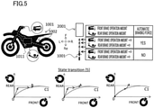
- FIG. 5 shows a part of the state transition 4 shown in FIG. 4 .
- the rear wheel braking force may be maintained whereas the front wheel braking force may be increased.
- the front wheel braking force may be decreased whereas the rear wheel braking force may be increased.
- the front wheel braking force may be increased and the rear wheel braking force may be increased.
- An AEB control device 1011 of the Sixth Embodiment includes the following arrangements, in addition to those of the First Embodiment, Second Embodiment, Third Embodiment, Fourth Embodiment, or Fifth Embodiment.
- the AEB control device 1011 controls the front wheel braking force and the rear wheel braking force that are automatically generated, so that the state transition of the front wheel braking force and the rear wheel braking force is the state transition 6 described below.
- State transition 6 Within a range excluding a range in which the rear wheel braking force is small as compared to the ideal braking force distribution C1 when one rider rides, a state where the total braking force which is the sum total of the front wheel braking force and the rear wheel braking force increases transitions to a state where the total braking force is maintained.
- the state where the total braking force of the front wheel braking force and the rear wheel braking force increases within the above-described range may be a state transitioned from a state where the front wheel braking force and the rear wheel braking force are both zero or may be a state transitioned from a state where the front wheel braking force and the rear wheel braking force are both zero, via another state.
- the state where the total braking force of the front wheel braking force and the rear wheel braking force increases within the above-described range may be a state of departing from the ideal braking force distribution C1 when one rider rides, a state of departing from the ideal braking force distribution C1 when one rider rides and a braking force distribution at which the front wheel braking force is zero, a state of coming close to the ideal braking force distribution C1 when one rider rides so that the total braking force increases, or a state of changing along the ideal braking force distribution C1 when one rider rides so that the total braking force increases.
- L1 indicates a braking force distribution with which the total braking force is maintained.
- the front wheel braking force may be decreased whereas the rear wheel braking force may be increased.
- the front wheel braking force may be increased whereas the rear wheel braking force may be decreased.
- the front wheel braking force and the rear wheel braking force may be maintained.
- An AEB control device 1011 of the Seventh Embodiment includes the following arrangements, in addition to those of the First Embodiment, Second Embodiment, Third Embodiment, Fourth Embodiment, Fifth Embodiment or Sixth Embodiment.
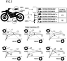
- C2 indicates an ideal braking force distribution when two occupants ride
- L1 indicates the braking force distribution with which the total braking force is maintained
- L2 indicates a rear wheel braking force limit that is the limit of the rear wheel braking force.
- the AEB control device 1011 may control the braking force by utilizing the ideal braking force distribution C2 when two occupants ride.
- the AEB control device 1011 may perform control utilizing the braking force distribution L1 with which the total braking force is maintained, in addition to the control of the braking force utilizing the ideal braking force distribution C2 when two occupants ride. For example, the AEB control device 1011 may perform the transition to a state of changing along the ideal braking force distribution C2 when two occupants ride. For example, the AEB control device 1011 may perform the transition to a state where the front wheel braking force and the rear wheel braking force are changed toward the ideal braking force distribution C2 when two occupants ride.
- the AEB control device 1011 may perform the transition to a state of coming close to the ideal braking force distribution C1 when one rider rides from a state in where the front wheel braking force and the rear wheel braking force are on the ideal braking force distribution C2 when two occupants ride. In this case, for example, the transition may be performed so that the total braking force is maintained.
- the AEB control device 1011 may perform the transition to a state of coming close to the ideal braking force distribution C2 when two occupants ride from a state where the front wheel braking force and the rear wheel braking force are on the ideal braking force distribution C1 when one rider rides. In this case, the transition may be performed so that the total braking force is maintained.
- a range excluding a range in which the rear wheel braking force is small as compared to the ideal braking force distribution when one rider rides in the present teaching and the embodiments does not encompass a case where the rear wheel braking force is infinite. This is because it is impossible to generate braking force exceeding the rear wheel braking force limit.
- a range excluding a range in which the rear wheel braking force is small as compared to the ideal braking force distribution when one rider rides encompasses a condition that the range is equal to or smaller than the rear wheel braking force limit.
- a range excluding a range in which the rear wheel braking force is small as compared to the ideal braking force distribution when one rider rides can be rephrased to a range which excludes a range in which the rear wheel braking force is smaller than the ideal braking force distribution when one rider rides and is equal to or lower than the rear wheel braking force limit.
- the AEB control device 1011 of the First Embodiment, Second Embodiment, Third Embodiment, Fourth Embodiment, Fifth Embodiment, Sixth Embodiment, or Seventh Embodiment may be arranged as described below.
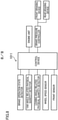
- the AEB control device 1011 shown in FIG. 7 has a brake assist control function.
- the AEB control device 1011 is electrically connected to a front braking device, a rear braking device, a front detection device which is required to determine a margin which is acquired based on the relationship between an obstacle 2001 and a host vehicle 1001, and a brake operation state detector which is required to acquire an operation amount of a brake operator.
- the AEB control device 1011 is electrically connected to an engine unit.
- the AEB control device 1011 may or may not be electrically connected to a leaning angle related physical quantity detector required to acquire at least one of leaning angular speed or leaning angular acceleration.
- the AEB control device 1011 may or may not be electrically connected to a yaw angle related physical quantity detector required to acquire at least one of yaw angular speed or yaw angular acceleration.
- the front braking device is an example of the front wheel brake or an example of the brake.
- the rear braking device is an example of the rear wheel brake or an example of the brake.
- the leaning angle related physical quantity detector is an example of the leaning angle related sensor.
- the front sensor is an example of the margin related sensor.
Landscapes
- Engineering & Computer Science (AREA)
- Mechanical Engineering (AREA)
- Transportation (AREA)
- Hydraulic Control Valves For Brake Systems (AREA)
- Regulating Braking Force (AREA)
Abstract
Description
- The present teaching relates to a leaning vehicle including an AEB (Autonomous Emergency Braking) control device which is configured to automatically control braking force without requiring an operation of at least one of a front wheel brake operator or a rear wheel brake operator, based on a margin acquired based on the relationship between an obstacle and a host vehicle.
- For example,
Patent Literature 1 proposes a leaning vehicle including an AEB control device which is configured to automatically control braking force without requiring an operation of at least one of a front wheel brake operator or a rear wheel brake operator, based on a margin acquired based on the relationship between an obstacle and a host vehicle and corresponds to the obstacle. The leaning vehicle includes the front wheel brake operator and the rear wheel brake operator that are operated by a rider, and leans rightward in the vehicle left-right direction when turning right and leans leftward in the vehicle left-right direction when turning left. - [Patent Literature 1]
Japanese Unexamined Patent Publication No. 2017-024644 - There is a need for a leaning vehicle including an AEB control device which is configured to perform control different from the control recited in
Patent Literature 1. - An object of the present teaching is to provide a leaning vehicle which includes a front wheel brake operator and a rear wheel brake operator that are operated by a rider, leans rightward in a vehicle left-right direction when turning right and leans leftward in the vehicle left-right direction when turning left, and includes an AEB control device configured to perform control different from known control schemes.
- The inventors of the present teaching diligently studied an assisting braking force automatically generated in a leaning vehicle including an AEB control device which is configured to automatically generate braking force without requiring an operation of at least one of a front wheel brake operator or a rear wheel brake operator, based on a margin acquired based on the relationship between an obstacle and a host vehicle, and found a novel control scheme. According to the novel control scheme, in a leaning vehicle which includes a front wheel brake operator and a rear wheel brake operator that are operated by a rider and leans rightward in a vehicle left-right direction when turning right and leans leftward in the vehicle left-right direction when turning left, braking force which is automatically generated based on a margin acquired based on the relationship between an obstacle and a host vehicle is controlled in consideration of the balance between a front wheel braking force and a rear wheel braking force relative to an ideal braking force distribution when one rider rides. In particular, the leaning vehicle includes the front wheel brake operator and the rear wheel brake operator. On this account, the rider may control the action of the leaning vehicle by adjusting the balance between the front wheel brake operator and the rear wheel brake operator. For example, when the braking force is generated at the front wheel in a state in which braking force is generated at neither the front wheel nor the rear wheel, a suspension of the front wheel contracts whereas a suspension of the rear wheel elongates, with the result that the leaning vehicle exhibits a pitching action. At this stage, loads acting on the front wheel and the rear wheel are varied. It is considered that the rider adjusts the balance between the front wheel brake operator and the rear wheel brake operator in consideration of such an action. The above-described action is specific to leaning vehicles each including a front wheel brake operator and a rear wheel brake operator, and is not observed in automobiles.
- The present teaching is based on a technical idea that a braking force which is generated automatically is controlled in consideration of the balance between a front wheel braking force and a rear wheel braking force relative to an ideal braking force distribution when one rider rides. This technical idea is totally different from the technical idea of
Patent Literature 1, i.e., an automatically-generated braking force is separated into a front wheel braking force and a rear wheel braking force, and a braking force is controlled with the use of the limits of front wheel braking force and rear wheel braking force, respectively. - A leaning vehicle including an AEB control device of an embodiment of the present teaching has the following structures.
- A leaning vehicle comprises: a front wheel brake operator and a rear wheel brake operator that are operated by a rider; and an AEB (Autonomous Emergency Braking) control device which is mounted on a leaning vehicle body frame leaning rightward in a vehicle left-right direction when turning right and leaning leftward in the vehicle left-right direction when turning left and is configured to automatically control the front wheel braking force and the rear wheel braking force without requiring an operation of at least one of the front wheel brake operator or the rear wheel brake operator, based on a margin acquired based on the relationship between an obstacle and the leaning vehicle. The AEB control device controls the front wheel braking force and the rear wheel braking force that are automatically generated, so that the state transition of the front wheel braking force and the rear wheel braking force is a
state transition 1 described below. - State transition 1: Within a range excluding a range in which the rear wheel braking force is small as compared to an ideal braking force distribution when one rider rides, a state where the front wheel braking force and the rear wheel braking force are both zero transitions to a state of changing along positions where the front wheel braking force and the rear wheel braking force are both not zero.
- A leaning vehicle including an AEB control device of an embodiment of the present teaching may have the following structure.
- The AEB control device controls the front wheel braking force and the rear wheel braking force that are automatically generated, so that the state transition of the front wheel braking force and the rear wheel braking force is a
state transition 2 described below. - State transition 2: Within a range excluding a range in which the rear wheel braking force is small as compared to the ideal braking force distribution when one rider rides, a state where the front wheel braking force and the rear wheel braking force are both zero transitions to a state of departing from the ideal braking force distribution when one rider rides and a braking force distribution at which the front wheel braking force is zero.
- A leaning vehicle including an AEB control device of an embodiment of the present teaching may have the following structure.
- The AEB control device controls the front wheel braking force and the rear wheel braking force that are automatically generated, so that the state transition of the front wheel braking force and the rear wheel braking force is a
state transition 3 described below. - State transition 3: Within a range excluding a range in which the rear wheel braking force is small as compared to the ideal braking force distribution when one rider rides, a state of departing from the ideal braking force distribution when one rider rides transitions to a state of coming close to the ideal braking force distribution when one rider rides so that the total braking force which is the sum total of the front wheel braking force and the rear wheel braking force increases.
- A leaning vehicle including an AEB control device of an embodiment of the present teaching may have the following structure. The AEB control device controls the front wheel braking force and the rear wheel braking force that are automatically generated, so that the state transition of the front wheel braking force and the rear wheel braking force is a
state transition 4 described below. - State transition 4: Within a range excluding a range in which the rear wheel braking force is small as compared to the ideal braking force distribution when one rider rides, transition to a state of changing along the ideal braking force distribution when one rider rides so that the total braking force which is the sum total of the front wheel braking force and the rear wheel braking force increases occurs.
- A leaning vehicle including an AEB control device of an embodiment of the present teaching may have the following structure. The AEB control device controls the front wheel braking force and the rear wheel braking force that are automatically generated, so that the state transition of the front wheel braking force and the rear wheel braking force is a
state transition 5 described below. - State transition 5: Within a range excluding a range in which the rear wheel braking force is small as compared to the ideal braking force distribution when one rider rides, a state of changing along the ideal braking force distribution when one rider rides so that the total braking force increases transitions to a state of departing from the ideal braking force distribution when one rider rides.
- A leaning vehicle including an AEB control device of an embodiment of the present teaching may have the following structure.
- The AEB control device controls the front wheel braking force and the rear wheel braking force that are automatically generated, so that the state transition of the front wheel braking force and the rear wheel braking force is a
state transition 6 described below. - State transition 6: Within a range excluding a range in which the rear wheel braking force is small as compared to the ideal braking force distribution when one rider rides, a state where the total braking force which is the sum total of the front wheel braking force and the rear wheel braking force increases transitions to a state where the total braking force is maintained.
- With the arrangements above, in a leaning vehicle which includes a front wheel brake operator and a rear wheel brake operator that are operated by a rider and leans rightward in a vehicle left-right direction when turning right and leans leftward in the vehicle left-right direction when turning left, the braking force which is automatically generated based on a margin acquired based on the relationship between an obstacle and a host vehicle can be controlled in consideration of the balance between the front wheel braking force and the rear wheel braking force relative to an ideal braking force distribution when one rider rides.
- The present teaching is based on a technical idea that the braking force which is generated automatically is controlled in consideration of the balance between the front wheel braking force and the rear wheel braking force relative to an ideal braking force distribution when one rider rides. This technical idea is totally different from the technical idea of
Patent Literature 1, i.e., automatically-generated braking force is separated into front wheel braking force and rear wheel braking force, and the braking force is controlled with the use of the limit of each force. - The present teaching is therefore able to provide a leaning vehicle which includes a front wheel brake operator and a rear wheel brake operator that are operated by a rider, leans rightward in a vehicle left-right direction when turning right and leans leftward in the vehicle left-right direction when turning left, and includes an AEB control device configured to perform a control different from known control schemes.
- The AEB control device may control the front wheel braking force and the rear wheel braking force that are automatically generated, so that the state transition of the front wheel braking force and the rear wheel braking force is a state transition 8 described below.
- State transition 8: Within a range excluding a range in which the rear wheel braking force is small as compared to the ideal braking force distribution when one rider rides on the leaning vehicle, transition to a state where the rear wheel braking force is increased and the front wheel braking force is decreased while the total braking force is maintained occurs.
- The AEB control device may control the front wheel braking force and the rear wheel braking force that are automatically generated, so that the state transition of the front wheel braking force and the rear wheel braking force is a state transition 9 described below.
- State transition 9: Within a range excluding a range in which the rear wheel braking force is small as compared to the ideal braking force distribution when one rider rides on the leaning vehicle, when the vehicle speed decreases either after the total braking force is increased or while the total braking force is being increased, transition to a state where the rear wheel braking force is increased and the front wheel braking force is decreased occurs.
- The AEB control device may control the front wheel braking force and the rear wheel braking force that are automatically generated, so that the state transition of the front wheel braking force and the rear wheel braking force is a state transition 10 described below.
- State transition 10: Within a range excluding a range in which the rear wheel braking force is small as compared to the ideal braking force distribution when one rider rides on the leaning vehicle, a state where the front wheel braking force and the rear wheel braking force are maintained transitions to a state where the rear wheel braking force increases whereas the front wheel braking force decreases.
- The AEB control device may control the front wheel braking force and the rear wheel braking force that are automatically generated, so that the state transition of the front wheel braking force and the rear wheel braking force is a state transition 11 described below.
- State transition 11: Within a range excluding a range in which the rear wheel braking force is small as compared to the ideal braking force distribution when one rider rides on the leaning vehicle, transition to a state where the front wheel braking force and the rear wheel braking force are maintained occurs.
- In the present teaching and the embodiments, a state of changing along positions where the front wheel braking force and the rear wheel braking force are both not zero is a state where the front wheel braking force changes within a range excluding zero and the rear wheel braking force changes within a range excluding zero. In other words, the state excludes a state where the rear wheel braking force changes while the front wheel braking force remains at zero and a state where the front wheel braking force changes while the rear wheel braking force remains at zero.
- An ideal braking force distribution when one rider rides on the leaning vehicle in the present teaching and the embodiments is an ideal braking force distribution calculated with the assumption that the load on the leaning vehicle is only one rider who has a typical weight. The ideal braking force distribution when one rider rides on the leaning vehicle is calculated by a known method. The weight of the rider is, for example, 50kg. This weight of the rider is a relatively lightweight as compared to an average weight of Japanese people including women. The ideal braking force distribution when one rider rides on the leaning vehicle is a distribution of the front wheel braking force and the rear wheel braking force which is most efficient for generating deceleration (negative acceleration). Only one ideal braking force distribution when one rider rides is set for a single value of total braking force. In other words, only one ideal braking force against a front wheel and only one ideal braking force against a rear wheel are set for a single value of total braking force.
- Ideal braking force Bf[N] against the front wheel and ideal braking force Br[N] against the rear wheel are calculated by the following mathematical expression, in accordance with a road surface µ (coefficient of friction on a road). In the expression, αm indicates a deceleration coefficient, W[N] indicates vehicle weight, Wf0[N] indicates a front wheel shared load at vehicle stop, Wr0[N] indicates a rear wheel shared load at vehicle stop, H[m] indicates ground height of the gravity center, and L[m] indicates the wheelbase. The ideal braking force distribution when one rider rides is therefore calculated from vehicle dimensions. Examples of the dimensions include the vehicle weight, the distance in the vehicle front-rear direction between the gravity center and the grounding point of a front wheel, the distance in the vehicle front-rear direction between the gravity center and the grounding point of a rear wheel, and the ground height of the gravity center.

- When two occupants including a rider ride on a leaning vehicle, a brake assist control device of the present teaching may control the braking force by utilizing the ideal braking force distribution when one rider rides according to the present teaching or an ideal braking force distribution when two occupants ride. Hereinafter, the ideal braking force distribution when one rider rides will be simply referred to as the ideal braking force distribution.
- A state of coming close to the ideal braking force distribution when one rider rides in the present teaching and the embodiments includes a state of coming close to a position on the ideal braking force distribution when one rider rides from a position not on the ideal braking force distribution when one rider rides. In this case, the AEB control device controls at least one of the front wheel braking force or the rear wheel braking force so that the front wheel braking force and the rear wheel braking force come close to the ideal braking force distribution when one rider rides. The state of coming close to the ideal braking force distribution when one rider rides includes a state where the above-described control of causing the front wheel braking force and the rear wheel braking force to come close to the ideal braking force distribution has been done. For example, the state of coming close to the ideal braking force distribution when one rider rides is a state of coming close to a position on the ideal braking force distribution when one rider rides from a position not on the ideal braking force distribution when one rider rides and reaching a position immediately before the ideal braking force distribution when one rider rides. For example, the state of coming close to the ideal braking force distribution when one rider rides is a state of coming close to a position on the ideal braking force distribution when one rider rides from a position not on the ideal braking force distribution when one rider rides, going across the ideal braking force distribution when one rider rides, and reaching a position not on the ideal braking force distribution when one rider rides. A state of coming close to the ideal braking force distribution when two occupants ride is identical with the state of coming close to the ideal braking force distribution when one rider rides, except that one rider is replaced with two occupants.
- A state of changing along the ideal braking force distribution when one rider rides in the present teaching and the embodiments encompasses a state where the front wheel braking force and the rear wheel braking force change on the ideal braking force distribution when one rider rides and a state where the front wheel braking force and/or the rear wheel braking force change while keeping a distance from the ideal braking force distribution when one rider rides. This distance may not be constant. The ideal braking force distribution when one rider rides expressed by a curved line. However, the state of changing along the ideal braking force distribution when one rider rides may be a state of changing linearly along the ideal braking force distribution when one rider rides. A state changing along the ideal braking force distribution when two occupants ride is identical with the state changing along the ideal braking force distribution when one rider rides, except that one rider is replaced with two occupants.
- A state of departing from the ideal braking force distribution when one rider rides in the present teaching and the embodiments is a state where the front wheel braking force and/or the rear wheel braking force changes from a position where the shortest distance from the ideal braking force distribution when one rider rides is short to a position where the shortest distance from the ideal braking force distribution when one rider rides is long. A state of departing from the ideal braking force distribution when two occupants ride is identical to the state of departing from the ideal braking force distribution when one rider rides, except that one rider is replaced with two occupants.
- In the present teaching and the embodiments, a transition to a state of changing along ideal braking force distribution when one rider rides may indicate a transition from a state where the front wheel braking force and the rear wheel braking force are both zero to a state of changing along an ideal braking force distribution when one rider rides, without the intermediary of another state, or may indicate a transition from a state where the front wheel braking force and the rear wheel braking force are both zero to a state of changing along an ideal braking force distribution when one rider rides, via a state of not changing along the ideal braking force distribution when one rider rides.
- A leaning vehicle of the present teaching and embodiments is a vehicle which includes a leaning vehicle body frame structured to lean rightward in the vehicle left-right direction when turning right and lean leftward in the vehicle left-right direction when turning left. The vehicle includes at least one front wheel and at least one rear wheel. The leaning vehicle may include two front wheels and one or two rear wheels. The leaning vehicle may include one front wheel and one or two rear wheels. In the leaning vehicle, either the front wheel or the rear wheel may be steered. The leaning vehicle includes a driving source. The driving source may be an engine, a motor driven by electricity, or a hybrid driving source including both an engine and a motor. The leaning vehicle body frame is a member which mainly receives stress in the leaning vehicle. The leaning vehicle body frame may be a frame formed by combining a plurality of components, or may be an integrally-molded frame.
- The leaning vehicle includes a front wheel brake, a rear wheel brake, and at least one brake operator. The front wheel brake is configured to apply the front wheel braking force to the front wheel. The rear wheel brake is configured to apply the rear wheel braking force to the rear wheel. The front wheel brake, the rear wheel brake, or a combination of the front wheel brake and the rear wheel brake may be simply referred to as a brake. The brake operator may be a lever operated by a hand of the rider or a pedal operated by a foot of the rider. The leaning vehicle may include a front wheel brake operator and a rear wheel brake operator as the brake operator. The front wheel brake operator may be arranged to be able to operate not only the front wheel brake but also the rear wheel brake. The rear wheel brake operator may be arranged to be able to operate not only the rear wheel brake but also the front wheel brake. The front wheel brake and the rear wheel brake may be operated by a single brake operator. A brake operation in the present teaching and the embodiments indicates an action to operate a brake operator provided in the leaning vehicle. A brake operation amount indicates to what extent the rider performs the brake operation. The brake operation amount may be information directly indicating the brake operation amount, or information indirectly indicating the brake operation amount, e.g., information correlated to the brake operation amount. Acquisition of a brake operation amount indicates that information indicating a brake operation amount is directly acquired or information indicating a brake operation amount is indirectly acquired.
- An AEB control device of the present teaching and the embodiments is a controller having a function of controlling an automatically-generated braking force. The AEB control device may have other functions. For example, when an ABS control device having a function of antilock braking system (ABS) has a function of controlling an automatically-generated braking force, the ABS control device is regarded as an AEB control device. The AEB control device of the present teaching and the embodiments is electrically connected to a brake and a margin related sensor which is required to determine a margin acquired based on the relationship between an obstacle and a host vehicle. The AEB control device of the present teaching and the embodiments may be electrically connected to a leaning angle related sensor which is required to acquire at least one of leaning angular speed or leaning angular acceleration. Examples of the leaning angle related sensor include an IMU (Inertial Measurement Unit), a GPS (Global Positioning System), and a camera for obtaining a leaning angle from an image. The margin related sensor is, for example, a camera taking images ahead of the leaning vehicle, a millimeter wave radar, a LIDAR, or a combination of these devices. Each sensor may be of any type as long as the functions described above are achieved. The brake has a function of generating the braking force upon receiving an electrical signal from the AEB control device. The brake may be of any type as long as the function described above is achieved. The AEB control device may be electrically connected to a sensor different from the sensors above. The AEB control device may be controlled based on a signal acquired by a sensor different from the sensors above. The AEB control device may have a function of the antilock braking system (ABS). In this case, the AEB control device may be electrically connected to a sensor capable of detecting a slipping state of a wheel. The AEB control device may control an electrically-connected brake which is a brake not mechanically but electrically connected to a brake operator. The AEB control device may control a brake that involves both mechanical connection and electrical connection.
- In the present teaching and the embodiments, a margin acquired based on the relationship between an obstacle and a host vehicle is a margin when a rider deals with an obstacle. The margin is acquired based on the relative speed between an obstacle and a host vehicle, for example. The margin is information such as a numerical value and the magnitude of an analog signal. When the margin is higher than a reference value, there is a margin in comparison with the reference value. The reference value may be set in advance in accordance with each type of the leaning vehicles. The margin may be corrected or learned based on signals obtained by various types of sensors. The margin may be information directly indicating the margin or information indirectly indicating the margin such as information correlated with the margin. Acquisition of a margin indicates acquisition of information directly indicating the margin or acquisition of information indirectly indicating the margin.
- A leaning angle in the present teaching and the embodiments is a tilt angle in the left-right direction of the leaning vehicle relative to the vertical direction. The tilt angle in the left-right direction of the leaning vehicle relative to the vertical direction indicates the tilt angle in the left-right direction of the leaning vehicle body frame of the leaning vehicle relative to the vertical direction. When the leaning angle is zero, the leaning vehicle is in an upright state in the left-right direction of the leaning vehicle. A state in which the absolute value of the leaning angle decreases is a state in which the leaning vehicle shifts from a state of leaning in the left-right direction of the leaning vehicle to the upright state. A state in which the absolute value of the leaning angle increases is a state in which the leaning vehicle shifts from the upright state to the state of leaning in the left-right direction of the leaning vehicle. The time change rate of the leaning angle during this shift is equivalent to the leaning angular speed. The time change rate of the leaning angular speed is equivalent to the leaning angular acceleration. The leaning angular speed or the leaning angular acceleration may be information directly indicating the leaning angular speed or the leaning angular acceleration, or may be information indirectly indicating the leaning angular speed or the leaning angular acceleration, such as information correlated to the leaning angular speed or the leaning angular acceleration. Acquisition of the leaning angular speed or the leaning angular acceleration indicates acquisition of information directly indicating the leaning angular speed or the leaning angular acceleration or acquisition of information indirectly indicating the leaning angular speed or the leaning angular acceleration. Examples of the leaning angle related sensor include an IMU (Inertial Measurement Unit), a GPS (Global Positioning System), and a camera for obtaining a leaning angle from an image.
- The AEB control device of the present teaching and the embodiments is a driving assist control device of one type. In addition to this, as a driving assist control device, a brake assist control device has been proposed. These two devices are technologically different in the following points. The brake assist control device is a technology of controlling the assisting braking force based on an operation of the brake operator by the rider. Meanwhile, the AEB control device is a technology of automatically controlling the braking force even if the brake operator is not operated. These two control devices are significantly different technologies from the viewpoint of the brake operation by the rider. In addition to the above, the brake assist control device is a technology designed for scenes in which the brake operator is operated by the rider. The AEB control device is a technology designed for scenes in which the brake operator is not operated. These two control devices are significantly different technologies from the viewpoint of the brake operation by the rider. The AEB control device may be combined with the brake assist control device even though they are different technologies. For example, when a brake assist control device having a brake assist control function has a function of controlling AEB, the brake assist controller is regarded as an AEB control device.
- The hardware structures of the AEB control device of the present teaching and the embodiments and of the leaning vehicle including this control device are not detailed in this description. Because the features of the present teaching and the embodiments are technologies related to control, a person with ordinary skill in the art would understand that the leaning vehicle including the AEB control device recited in the present teaching and the embodiments can be embodied by the hardware structures of a AEB control device recited in
Patent Literature 1 or another known document and the hardware structures of a leaning vehicle including this control device. The figure of relationship of control schemes indicates each brake operation amount and each braking force. A person with ordinary skill in the art would understand what is meant by each figure, and would be able to embody the disclosure by means of a known hardware structure. - In the present teaching and the embodiments, to control the braking force indicates to control the brake in order to acquire the braking force. For example, when a brake whose braking force varies in accordance with a hydraulic pressure is employed, to control the braking force indicates to control the hydraulic pressure. For example, when a drum brake whose braking force varies in accordance with the rotational angle of a lever is employed, to control the braking force indicates to control the rotational angle of the lever. A specific target of control is changed in accordance with the type of the brake.
- In the present teaching and the embodiments, to increase / decrease / maintain total braking force is not limited to a case where actual total braking force is increased / decreased / maintained. To increase / decrease / maintain total braking force encompasses a case where control of increasing / decreasing / maintaining total braking force is considered to be performed even if actual total braking force is not increased / decreased / maintained. To increase / decrease / maintain the front wheel braking force and to increase / decrease / maintain the rear wheel braking force are similarly defined in the present teaching and the embodiments.
- In the present teaching and the embodiments, a control based on A does not indicate that information used for the control is limited to A. The control based on A indicates that information based on which the control is performed includes information which is not A, and encompasses a case where the control is performed based on A and information which is not A.
- In the present teaching and embodiments, at least one of plural options encompasses all conceivable combinations of the options. At least one of plural options may be one of the options, some of the options, or all of the options. For example, at least one of A, B, or C indicates only A, only B, only C, A and B, A and C, B and C, or A, B, and C.
- In the claims, when the number of a constituent feature is not clearly specified and the constituent feature is expressed in a singular form in English, the number of the constituent feature may be more than one in the present teaching. In the present teaching, the number of the constituent features may be only one.
- In the present teaching and the embodiments, terms "including", "comprising", "having", and derivatives thereof are used to encompass not only listed items and equivalents thereof but also additional items.
- In the present teaching and the embodiments, the terms "mounted", "connected", "coupled", and "supported" are used in broad sense. Specifically, not only direct attachment, connection, coupling, and support but also indirect attachment, connection, coupling, and support are included. Further, connected and coupled are not limited to physical or mechanical connections and couplings. They also include direct or indirect electrical connections and couplings.
- Unless otherwise defined, all terms (technical and scientific terms) used in this specification and claims indicate meanings typically understood by a person with ordinary skill in the art in the technical field to which the present teaching belongs. Terms such as those defined in commonly used dictionaries are to be interpreted as having meaning that is consistent with their meaning in the context of the relevant art and the present disclosure, and are not to be interpreted in an idealized or excessively formal sense.
- In the present teaching and the embodiments, the term "preferable" is non-exclusive. The term "preferable" means "preferable but not limited to". In this specification, an arrangement which is "preferable" exerts at least the above-described effects of the arrangement of
claim 1. In this specification, the term "may" is non-exclusive. The term "may" indicate "may but not must". In this specification, an arrangement which is explained by using the term "may" exerts at least the above-described effects of the arrangement ofclaim 1. - In the present teaching and the embodiments, the preferred arrangements of the different aspects described above may be variously combined. Before the embodiments of the present teaching are detailed, it is informed that the present teaching is not limited to the configurations and layout of elements described below and/or shown in drawings. The present teaching is also applicable to embodiments other than the embodiments described later. The present teaching may be implemented as an embodiment other than the below-described embodiment. Furthermore, the present teaching may be implemented by suitably combining below-described embodiments and modifications.
-
-
FIG. 1 outlines a leaning vehicle of the First Embodiment of the present teaching. -
FIG. 2 outlines a leaning vehicle of the Second Embodiment of the present teaching. -
FIG. 3 outlines a leaning vehicle of the Third Embodiment of the present teaching. -
FIG. 4 outlines a leaning vehicle of the Fourth Embodiment of the present teaching. -
FIG. 5 outlines a leaning vehicle of the Fifth Embodiment of the present teaching. -
FIG. 6 outlines a leaning vehicle of the Sixth Embodiment of the present teaching. -
FIG. 7 outlines a leaning vehicle of the Seventh Embodiment of the present teaching. -
FIG. 8 outlines a leaning vehicle of the Eighth Embodiment of the present teaching. - In the drawings, U indicates a direction upward from a leaning vehicle, D indicates a direction downward from the leaning vehicle, L indicates a direction leftward from the leaning vehicle, R indicates a direction rightward from the leaning vehicle, F indicates a direction forward from the leaning vehicle, and Re indicates a direction rearward from the leaning vehicle.
- In the figures, a position where both the front wheel braking force and the rear wheel braking force are zero is indicated by a black circle. In the figures, an arrow starting from each black circle falls within a range in which the rear wheel braking force is larger than an ideal braking force distribution when one rider rides on a leaning
vehicle 1001, except the starting point of the arrow. In the figures, a line segment of an arrow starting from each black circle, which excludes the starting point of the arrow, indicates at least a part of a state of changing along positions where the front wheel braking force and the rear wheel braking force are both not zero. A line segment of an arrow starting from each black circle, which excludes the starting point of the arrow, indicates either a state of changing along the ideal braking force distribution when one rider rides or a state of departing from the ideal braking force distribution when one rider rides. In the figures, an arrow connected to an arrow starting from a black circle as a starting point indicates a subsequent state. The subsequent state may be a state of coming close to the ideal braking force distribution when one rider rides, for example. An arrow indicating a state of changing along positions where the front wheel braking force and the rear wheel braking force are both not zero, a state of changing along the ideal braking force distribution when one rider rides, a state of departing from the ideal braking force distribution when one rider rides, or a state of coming close to the ideal braking force distribution when one rider rides may be a linear line, a curved line, a combination of a linear line and a curved line, or a combination of linear lines. In the figures, automatic braking force is a collective term of the front wheel braking force and the rear wheel braking force that are automatically controlled by anAEB control device 1011. InFIG. 2 to FIG. 7 , the maximum value of rear wheel braking force in the ideal braking force distribution when one rider rides is indicated by a dotted linear line. - The following will describe a leaning
vehicle 1001 of the First Embodiment of the present teaching with reference toFIG. 1 . The leaningvehicle 1001 includes a front wheel brake operator and a rear wheel brake operator that are operated by a rider. A leaningvehicle 1001 includes anAEB control device 1011 mounted on a leaning vehicle body frame 1002 which leans rightward in the vehicle left-right direction when turning right and leans leftward in the vehicle left-right direction when turning left. TheAEB control device 1011 is configured to automatically control the front wheel braking force and the rear wheel braking force without requiring an operation of at least one of the front wheel brake operator or the rear wheel brake operator, based on a margin acquired based on the relationship between anobstacle 2001 and ahost vehicle 1001. TheAEB control device 1011 controls the front wheel braking force and the rear wheel braking force that are automatically generated, so that the state transition of the front wheel braking force and the rear wheel braking force is thestate transition 1 described below. - State transition 1: Within a range excluding a range in which the rear wheel braking force is small as compared to an ideal braking force distribution C1 when one rider rides, a state where the front wheel braking force and the rear wheel braking force are both zero transitions to a state of changing along positions where the front wheel braking force and the rear wheel braking force are both not zero.
- For example, as shown in the left drawing included in
FIG. 1 and showing thestate transition 1, within a range where the above-described range overlaps a range between the ideal braking force distribution C1 when one rider rides and the braking force distribution at which the front wheel braking force is zero, the front braking force and the rear braking force may change along positions where the front wheel braking force and the rear wheel braking force are both not zero. For example, as shown in the right drawing included inFIG. 1 and showing thestate transition 1, within the above-described range, the distribution of the braking forces may change along positions on the ideal braking force distribution C1 when one rider rides, where the front wheel braking force and the rear wheel braking force are both not zero. - At the position where the front wheel braking force and the rear wheel braking force are both zero, a rear wheel brake operation amount and a front wheel brake operation amount are both zero. In other words, at the position where the front wheel braking force and the rear wheel braking force are both zero, the rear wheel brake operator and the front wheel brake operator are both not operated.
- The following will describe a leaning
vehicle 1001 of the Second Embodiment of the present teaching with reference toFIG. 2 . AnAEB control device 1011 of the Second Embodiment includes the following arrangements, in addition to those of the First Embodiment. TheAEB control device 1011 controls the front wheel braking force and the rear wheel braking force that are automatically generated, so that the state transition of the front wheel braking force and the rear wheel braking force is thestate transition 2 described below. - State transition 2: Within a range excluding a range in which the rear wheel braking force is small as compared to the ideal braking force distribution C1 when one rider rides, a state where the front wheel braking force and the rear wheel braking force are both zero transitions to a state of departing from the ideal braking force distribution C1 when one rider rides and the braking force distribution at which the front wheel braking force is zero.
- For example, as shown in the two drawings included in
FIG. 2 and showing thestate transition 2, within a range where the above-described range overlaps a range between the ideal braking force distribution C1 when one rider rides and the braking force distribution at which the front wheel braking force is zero, the front wheel braking force and the rear wheel braking force may change along positions where the front wheel braking force and the rear wheel braking force are both not zero. For example, as shown in the left drawing included inFIG. 2 and showing thestate transition 2, within a range where the above-described range overlaps a range excluding a range larger than the maximum value of the rear wheel braking force of the ideal braking force distribution C1 when one rider ride, the front wheel braking force and the rear wheel braking force may depart from the ideal braking force distribution C1 when one rider rides and the braking force distribution at which the front wheel braking force is zero. For example, as shown in the right drawing included inFIG. 2 and showing thestate transition 2, after changing so as to depart from the ideal braking force distribution C1 when one rider rides and the braking force distribution at which the front wheel braking force is zero, within a range where the above-described range overlaps a range excluding a range larger than the maximum value of the rear wheel braking force of the ideal braking force distribution C1 when one rider ride, the front wheel braking force and the rear wheel braking force, and the change may continue within a range larger than the maximum value of the rear wheel braking force of the ideal braking force distribution C1 when one rider rides. Thestate transition 2 excludes, for example, a state transition of changing along positions on the ideal braking force distribution C1 when one rider rides, where the front wheel braking force and the rear wheel braking force are both not zero, which is indicated in the right drawing included inFIG. 1 and showing thestate transition 1. - The following will describe a leaning
vehicle 1001 of the Third Embodiment of the present teaching with reference toFIG. 3 . AnAEB control device 1011 of the Third Embodiment includes the following arrangements, in addition to those of the First Embodiment and Second Embodiment. TheAEB control device 1011 controls the front wheel braking force and the rear wheel braking force that are automatically generated, so that the state transition of the front wheel braking force and the rear wheel braking force is thestate transition 3 described below. - State transition 3: Within a range excluding a range in which the rear wheel braking force is small as compared to the ideal braking force distribution C1 when one rider rides, a state of departing from the ideal braking force distribution C1 when one rider rides transitions to a state of coming close to the ideal braking force distribution C1 when one rider rides so that the total braking force which is the sum total of the front wheel braking force and the rear wheel braking force increases.
- For example, as shown in
FIG. 3 , the state where the front wheel braking force and the rear wheel braking force depart from the ideal braking force distribution C1 when one rider rides within the above-described range may be a state transitioned from a state where the front wheel braking force and the rear wheel braking force are both zero. In the state of coming close to the ideal braking force distribution C1 when one rider rides by increasing the total braking force within the above-described range, for example, as shown inFIG. 3 , the rear wheel braking force may be maintained whereas the front wheel braking force may be increased. Alternatively, for example, as shown inFIG. 3 , the rear wheel braking force may be decreased whereas the front wheel braking force may be increased. Alternatively, for example, as shown inFIG. 3 , the rear wheel braking force may be increased and the front wheel braking force may be increased. Alternatively, for example, as shown inFIG. 3 , after the rear wheel braking force is maintained whereas the front wheel braking force is increased, the rear wheel braking force may be decreased whereas the front wheel braking force may be increased. - The following will describe a leaning
vehicle 1001 of the Fourth Embodiment of the present teaching with reference toFIG. 4 . AnAEB control device 1011 of the Fourth Embodiment includes the following arrangements, in addition to those of the First Embodiment, Second Embodiment, or Third Embodiment. TheAEB control device 1011 controls the front wheel braking force and the rear wheel braking force that are automatically generated, so that the state transition of the front wheel braking force and the rear wheel braking force is thestate transition 4 described below. State transition 4: Within a range excluding a range in which the rear wheel braking force is small as compared to the ideal braking force distribution C1 when one rider rides, transition to a state of changing along the ideal braking force distribution C1 when one rider rides so that the total braking force which is the sum total of the front wheel braking force and the rear wheel braking force increases occurs. - For example, the state of changing along the ideal braking force distribution C1 when one rider rides so that the total braking force increases, within the above-described range, may be a state transitioned from a state of coming close to the ideal braking force distribution C1 when one rider rides. For example, as shown in
FIG. 4 , thestate transition 4 may occur after the above-describedstate transition 3. - For example, as shown in
FIG. 4 , the state of changing along the ideal braking force distribution C1 when one rider rides so that the total braking force increases, within the above-described range, may be a state transitioned from a state where the front wheel braking force and the rear wheel braking force are both zero. - For example, the state of changing along the ideal braking force distribution C1 when one rider rides so that the total braking force increases may fall within a range where the above-described range overlaps a range excluding a range larger than the maximum value of the rear wheel braking force of the ideal braking force distribution C1 when one rider rides. For example, after changing along the ideal braking force distribution C1 when one rider rides so that the total braking force increases, within a range where the above-described range overlaps a range excluding a range larger than the maximum value of the rear wheel braking force of the ideal braking force distribution C1 when one rider rides, the change may continue within a range larger than the maximum value of the rear wheel braking force of the ideal braking force distribution C1 when one rider rides.
- Before the state of changing along the ideal braking force distribution C1 when one rider rides so that the total braking force increases, a state of changing within a range where the above-described range overlaps the range larger than the maximum value of the rear wheel braking force of the ideal braking force distribution C1 when one rider rides may or may not exist.
- The following will describe a leaning
vehicle 1001 of the Fifth Embodiment of the present teaching with reference toFIG. 5 . AnAEB control device 1011 of the Fifth Embodiment includes the following arrangements, in addition to those of the Fourth Embodiment. TheAEB control device 1011 controls the front wheel braking force and the rear wheel braking force that are automatically generated, so that the state transition of the front wheel braking force and the rear wheel braking force is thestate transition 5 described below. - State transition 5: Within a range excluding a range in which the rear wheel braking force is small as compared to the ideal braking force distribution C1 when one rider rides, a state of changing along the ideal braking force distribution C1 when one rider rides so that the total braking force increases transitions to a state of departing from the ideal braking force distribution C1 when one rider rides.
- The
state transition 5 occurs after thestate transition 4.FIG. 5 shows a part of thestate transition 4 shown inFIG. 4 . In the state where the front wheel braking force and the rear wheel braking force depart from the ideal braking force distribution C1 when one rider rides within the above-described range, for example, as shown inFIG. 5 , the rear wheel braking force may be maintained whereas the front wheel braking force may be increased. Alternatively, for example, as shown inFIG. 5 , the front wheel braking force may be decreased whereas the rear wheel braking force may be increased. Alternatively, for example, as shown inFIG. 5 , the front wheel braking force may be increased and the rear wheel braking force may be increased. - The following will describe a leaning
vehicle 1001 of the Sixth Embodiment of the present teaching with reference toFIG. 6 . AnAEB control device 1011 of the Sixth Embodiment includes the following arrangements, in addition to those of the First Embodiment, Second Embodiment, Third Embodiment, Fourth Embodiment, or Fifth Embodiment. TheAEB control device 1011 controls the front wheel braking force and the rear wheel braking force that are automatically generated, so that the state transition of the front wheel braking force and the rear wheel braking force is thestate transition 6 described below. - State transition 6: Within a range excluding a range in which the rear wheel braking force is small as compared to the ideal braking force distribution C1 when one rider rides, a state where the total braking force which is the sum total of the front wheel braking force and the rear wheel braking force increases transitions to a state where the total braking force is maintained.
- The state where the total braking force of the front wheel braking force and the rear wheel braking force increases within the above-described range may be a state transitioned from a state where the front wheel braking force and the rear wheel braking force are both zero or may be a state transitioned from a state where the front wheel braking force and the rear wheel braking force are both zero, via another state.
- The state where the total braking force of the front wheel braking force and the rear wheel braking force increases within the above-described range may be a state of departing from the ideal braking force distribution C1 when one rider rides, a state of departing from the ideal braking force distribution C1 when one rider rides and a braking force distribution at which the front wheel braking force is zero, a state of coming close to the ideal braking force distribution C1 when one rider rides so that the total braking force increases, or a state of changing along the ideal braking force distribution C1 when one rider rides so that the total braking force increases.
- In the figure, L1 indicates a braking force distribution with which the total braking force is maintained. In the state where the total braking force is maintained, for example, the front wheel braking force may be decreased whereas the rear wheel braking force may be increased. Alternatively, for example, the front wheel braking force may be increased whereas the rear wheel braking force may be decreased. Alternatively, for example, the front wheel braking force and the rear wheel braking force may be maintained.
- The following will describe a leaning
vehicle 1001 of the Seventh Embodiment of the present teaching with reference toFIG. 7 . AnAEB control device 1011 of the Seventh Embodiment includes the following arrangements, in addition to those of the First Embodiment, Second Embodiment, Third Embodiment, Fourth Embodiment, Fifth Embodiment or Sixth Embodiment. InFIG. 7 , C2 indicates an ideal braking force distribution when two occupants ride, L1 indicates the braking force distribution with which the total braking force is maintained, and L2 indicates a rear wheel braking force limit that is the limit of the rear wheel braking force. TheAEB control device 1011 may control the braking force by utilizing the ideal braking force distribution C2 when two occupants ride. TheAEB control device 1011 may perform control utilizing the braking force distribution L1 with which the total braking force is maintained, in addition to the control of the braking force utilizing the ideal braking force distribution C2 when two occupants ride. For example, theAEB control device 1011 may perform the transition to a state of changing along the ideal braking force distribution C2 when two occupants ride. For example, theAEB control device 1011 may perform the transition to a state where the front wheel braking force and the rear wheel braking force are changed toward the ideal braking force distribution C2 when two occupants ride. For example, theAEB control device 1011 may perform the transition to a state of coming close to the ideal braking force distribution C1 when one rider rides from a state in where the front wheel braking force and the rear wheel braking force are on the ideal braking force distribution C2 when two occupants ride. In this case, for example, the transition may be performed so that the total braking force is maintained. For example, theAEB control device 1011 may perform the transition to a state of coming close to the ideal braking force distribution C2 when two occupants ride from a state where the front wheel braking force and the rear wheel braking force are on the ideal braking force distribution C1 when one rider rides. In this case, the transition may be performed so that the total braking force is maintained. - It is easily understood that a range excluding a range in which the rear wheel braking force is small as compared to the ideal braking force distribution when one rider rides in the present teaching and the embodiments does not encompass a case where the rear wheel braking force is infinite. This is because it is impossible to generate braking force exceeding the rear wheel braking force limit. For a person with ordinary skill in the art, it is obvious that a range excluding a range in which the rear wheel braking force is small as compared to the ideal braking force distribution when one rider rides encompasses a condition that the range is equal to or smaller than the rear wheel braking force limit. For example, a range excluding a range in which the rear wheel braking force is small as compared to the ideal braking force distribution when one rider rides can be rephrased to a range which excludes a range in which the rear wheel braking force is smaller than the ideal braking force distribution when one rider rides and is equal to or lower than the rear wheel braking force limit.
- The following will describe a leaning
vehicle 1001 of the Eighth Embodiment of the present teaching with reference toFIG. 8 . TheAEB control device 1011 of the First Embodiment, Second Embodiment, Third Embodiment, Fourth Embodiment, Fifth Embodiment, Sixth Embodiment, or Seventh Embodiment may be arranged as described below. TheAEB control device 1011 shown inFIG. 7 has a brake assist control function. TheAEB control device 1011 is electrically connected to a front braking device, a rear braking device, a front detection device which is required to determine a margin which is acquired based on the relationship between anobstacle 2001 and ahost vehicle 1001, and a brake operation state detector which is required to acquire an operation amount of a brake operator. Furthermore, theAEB control device 1011 is electrically connected to an engine unit. TheAEB control device 1011 may or may not be electrically connected to a leaning angle related physical quantity detector required to acquire at least one of leaning angular speed or leaning angular acceleration. TheAEB control device 1011 may or may not be electrically connected to a yaw angle related physical quantity detector required to acquire at least one of yaw angular speed or yaw angular acceleration. - The front braking device is an example of the front wheel brake or an example of the brake. The rear braking device is an example of the rear wheel brake or an example of the brake. The leaning angle related physical quantity detector is an example of the leaning angle related sensor. The front sensor is an example of the margin related sensor.
-
- 1001
- leaning vehicle (host vehicle)
- 1002
- leaning vehicle body frame
- 2001
- obstacle
- 1011
- AEB (Autonomous Emergency Braking) control device
Claims (6)
- A leaning vehicle comprising: a front wheel brake operator and a rear wheel brake operator that are operated by a rider; and an AEB (Autonomous Emergency Braking) control device which is mounted on a leaning vehicle body frame leaning rightward in a vehicle left-right direction when turning right and leaning leftward in the vehicle left-right direction when turning left and is configured to automatically control a front wheel braking force and a rear wheel braking force without requiring an operation of at least one of the front wheel brake operator or the rear wheel brake operator, based on a margin acquired based on the relationship between an obstacle and the leaning vehicle, the AEB control device controlling the front wheel braking force and the rear wheel braking force that are automatically generated, so that a state transition of the front wheel braking force and the rear wheel braking force is:a state transition 1 with which, within a range excluding a range in which the rear wheel braking force is small as compared to an ideal braking force distribution when one rider rides, a state where the front wheel braking force andthe rear wheel braking force are both zero transitions to a state of changing along positions where the front wheel braking force and the rear wheel braking force are both not zero.
- The leaning vehicle according to claim 1, wherein the AEB control device controlling the front wheel braking force and the rear wheel braking force that are automatically generated, so that a state transition of the front wheel braking force and the rear wheel braking force is:a state transition 2 with which, within a range excluding a range in which the rear wheel braking force is small as compared to the ideal braking force distribution when one rider rides, a state where the front wheel braking force andthe rear wheel braking force are both zero transitions to a state of departing from the ideal braking force distribution when one rider rides and a braking force distribution at which the front wheel braking force is zero.
- The leaning vehicle according to claim 2, wherein the AEB control device controlling the front wheel braking force and the rear wheel braking force that are automatically generated, so that a state transition of the front wheel braking force and the rear wheel braking force is:
a state transition 3 with which, within a range excluding a range in which the rear wheel braking force is small as compared to the ideal braking force distribution when one rider rides, a state of departing from the ideal braking force distribution when one rider rides transitions to a state of coming close to ideal braking force distribution when one rider rides so that the total braking force which is the sum total of the front wheel braking force and the rear wheel braking force increases. - The leaning vehicle according to any one of claims 1 to 3, wherein the AEB control device controlling the front wheel braking force and the rear wheel braking force that are automatically generated, so that a state transition of the front wheel braking force and the rear wheel braking force is:
a state transition 4 with which, within a range excluding a range in which the rear wheel braking force is small as compared to the ideal braking force distribution when one rider rides, transition to a state of changing along the ideal braking force distribution when one rider rides so that the total braking force which is the sum total of the front wheel braking force and the rear wheel braking force increases occurs. - The leaning vehicle according to claim 4, wherein the AEB control device controlling the front wheel braking force and the rear wheel braking force that are automatically generated, so that a state transition of the front wheel braking force and the rear wheel braking force is:
a state transition 5 with which, within a range excluding a range in which the rear wheel braking force is small as compared to the ideal braking force distribution when one rider rides, a state of changing along the ideal braking force distribution when one rider rides so that the total braking force increases transitions to a state of departing from the ideal braking force distribution when one rider rides. - The leaning vehicle according to any one of claims 1 to 5, wherein the AEB control device controlling the front wheel braking force and the rear wheel braking force that are automatically generated, so that a state transition of the front wheel braking force and the rear wheel braking force is:
a state transition 6 with which, within a range excluding a range in which the rear wheel braking force is small as compared to the ideal braking force distribution when one rider rides, a state where the total braking force which is the sum total of the front wheel braking force and the rear wheel braking force increases transitions to a state where the total braking force is maintained.
Applications Claiming Priority (2)
| Application Number | Priority Date | Filing Date | Title |
|---|---|---|---|
| JP2019089733 | 2019-05-10 | ||
| PCT/JP2020/018867 WO2020230765A1 (en) | 2019-05-10 | 2020-05-11 | LEANING VEHICLE EQUIPPED WITH Autonomous Emergency Braking (AEB) CONTROL DEVICE |
Publications (3)
| Publication Number | Publication Date |
|---|---|
| EP3967586A1 true EP3967586A1 (en) | 2022-03-16 |
| EP3967586A4 EP3967586A4 (en) | 2022-07-13 |
| EP3967586B1 EP3967586B1 (en) | 2023-10-04 |
Family
ID=73289898
Family Applications (1)
| Application Number | Title | Priority Date | Filing Date |
|---|---|---|---|
| EP20805495.7A Active EP3967586B1 (en) | 2019-05-10 | 2020-05-11 | Leaning vehicle equipped with autonomous emergency braking (aeb) control device |
Country Status (2)
| Country | Link |
|---|---|
| EP (1) | EP3967586B1 (en) |
| WO (1) | WO2020230765A1 (en) |
Families Citing this family (1)
| Publication number | Priority date | Publication date | Assignee | Title |
|---|---|---|---|---|
| JPWO2024003666A1 (en) * | 2022-06-30 | 2024-01-04 |
Family Cites Families (7)
| Publication number | Priority date | Publication date | Assignee | Title |
|---|---|---|---|---|
| JP4526135B2 (en) * | 1999-03-17 | 2010-08-18 | 本田技研工業株式会社 | Front and rear wheel interlocking brake device for motorcycles |
| JP4429762B2 (en) * | 2004-02-24 | 2010-03-10 | 本田技研工業株式会社 | Brake equipment for motorcycles |
| JP2006069303A (en) * | 2004-08-31 | 2006-03-16 | Yamaha Motor Co Ltd | Brake device for motorcycle and motorcycle |
| JP5715523B2 (en) * | 2011-07-31 | 2015-05-07 | 本田技研工業株式会社 | Brake system for motorcycle |
| JP6214601B2 (en) | 2015-07-27 | 2017-10-18 | 本田技研工業株式会社 | Automatic braking system for saddle-ride type vehicles |
| JP6222746B2 (en) * | 2015-07-27 | 2017-11-01 | 本田技研工業株式会社 | Automatic braking system for saddle-ride type vehicles |
| JP2018177046A (en) * | 2017-04-17 | 2018-11-15 | ローベルト ボッシュ ゲゼルシャフト ミット ベシュレンクテル ハフツング | Control device, control method and brake system |
-
2020
- 2020-05-11 EP EP20805495.7A patent/EP3967586B1/en active Active
- 2020-05-11 WO PCT/JP2020/018867 patent/WO2020230765A1/en not_active Ceased
Also Published As
| Publication number | Publication date |
|---|---|
| WO2020230765A1 (en) | 2020-11-19 |
| EP3967586B1 (en) | 2023-10-04 |
| EP3967586A4 (en) | 2022-07-13 |
Similar Documents
| Publication | Publication Date | Title |
|---|---|---|
| EP3281832B1 (en) | Travel control device for vehicle | |
| US10889272B2 (en) | Autonomous emergency braking apparatus and control method thereof | |
| CN102421645B (en) | Method and apparatus for performing closed-loop or open-loop control of vehicle driving stability | |
| JP5475257B2 (en) | Lane departure prevention control device | |
| US20200089225A1 (en) | Control system of vehicle and control method of vehicle | |
| US10040509B1 (en) | Control system for electric bicycles | |
| KR101496612B1 (en) | Phasing of traction control based on vehicle speed and road slope | |
| EP3998188A1 (en) | Steering control device, steering control method, and steering control system | |
| US12466391B2 (en) | Vehicle, motion manager, and motion request correction method | |
| JP6936349B2 (en) | Vehicle control devices, vehicles, and vehicle control methods | |
| US20240101116A1 (en) | Method for automatically supporting a motor vehicle for traversing an exit of a main road | |
| US20040117099A1 (en) | Vehicular brake force control apparatus and method | |
| EP3967587B1 (en) | Leanable vehicle equipped with rider assistance control device for obstacles | |
| US10493990B2 (en) | Systems and methods for ride control blending in electric vehicles | |
| EP3967586B1 (en) | Leaning vehicle equipped with autonomous emergency braking (aeb) control device | |
| EP3967588B1 (en) | Leaning vehicle equipped with brake assist control device | |
| JP6964060B2 (en) | Vehicle control system | |
| US9505360B2 (en) | Method and arrangement for improving the performance of a safety-critical vehicle actuator | |
| JPWO2019031106A1 (en) | Braking control device | |
| EP3950455B1 (en) | Rider-assistance system and control method for rider-assistance system | |
| WO2020230770A1 (en) | Leaning vehicle equipped with brake assist control device | |
| CN119817077B (en) | Torque adjusting method and device and vehicle | |
| EP1481861B1 (en) | A method and a computer readable storage device for estimating tirc-to-road friction | |
| EP1852323B1 (en) | Rear end collision mitigation system for an automotive vehicle | |
| EP4353513A1 (en) | Vehicle control device |
Legal Events
| Date | Code | Title | Description |
|---|---|---|---|
| STAA | Information on the status of an ep patent application or granted ep patent |
Free format text: STATUS: THE INTERNATIONAL PUBLICATION HAS BEEN MADE |
|
| PUAI | Public reference made under article 153(3) epc to a published international application that has entered the european phase |
Free format text: ORIGINAL CODE: 0009012 |
|
| STAA | Information on the status of an ep patent application or granted ep patent |
Free format text: STATUS: REQUEST FOR EXAMINATION WAS MADE |
|
| 17P | Request for examination filed |
Effective date: 20211210 |
|
| AK | Designated contracting states |
Kind code of ref document: A1 Designated state(s): AL AT BE BG CH CY CZ DE DK EE ES FI FR GB GR HR HU IE IS IT LI LT LU LV MC MK MT NL NO PL PT RO RS SE SI SK SM TR |
|
| A4 | Supplementary search report drawn up and despatched |
Effective date: 20220613 |
|
| RIC1 | Information provided on ipc code assigned before grant |
Ipc: B60T 8/26 20060101ALI20220608BHEP Ipc: B60T 8/00 20060101ALI20220608BHEP Ipc: B60T 7/12 20060101ALI20220608BHEP Ipc: B62L 3/08 20060101AFI20220608BHEP |
|
| DAV | Request for validation of the european patent (deleted) | ||
| DAX | Request for extension of the european patent (deleted) | ||
| GRAP | Despatch of communication of intention to grant a patent |
Free format text: ORIGINAL CODE: EPIDOSNIGR1 |
|
| STAA | Information on the status of an ep patent application or granted ep patent |
Free format text: STATUS: GRANT OF PATENT IS INTENDED |
|
| INTG | Intention to grant announced |
Effective date: 20230418 |
|
| P01 | Opt-out of the competence of the unified patent court (upc) registered |
Effective date: 20230527 |
|
| GRAS | Grant fee paid |
Free format text: ORIGINAL CODE: EPIDOSNIGR3 |
|
| GRAA | (expected) grant |
Free format text: ORIGINAL CODE: 0009210 |
|
| STAA | Information on the status of an ep patent application or granted ep patent |
Free format text: STATUS: THE PATENT HAS BEEN GRANTED |
|
| AK | Designated contracting states |
Kind code of ref document: B1 Designated state(s): AL AT BE BG CH CY CZ DE DK EE ES FI FR GB GR HR HU IE IS IT LI LT LU LV MC MK MT NL NO PL PT RO RS SE SI SK SM TR |
|
| REG | Reference to a national code |
Ref country code: GB Ref legal event code: FG4D |
|
| REG | Reference to a national code |
Ref country code: CH Ref legal event code: EP |
|
| REG | Reference to a national code |
Ref country code: DE Ref legal event code: R096 Ref document number: 602020018769 Country of ref document: DE |
|
| REG | Reference to a national code |
Ref country code: IE Ref legal event code: FG4D |
|
| REG | Reference to a national code |
Ref country code: LT Ref legal event code: MG9D |
|
| REG | Reference to a national code |
Ref country code: NL Ref legal event code: MP Effective date: 20231004 |
|
| REG | Reference to a national code |
Ref country code: AT Ref legal event code: MK05 Ref document number: 1617513 Country of ref document: AT Kind code of ref document: T Effective date: 20231004 |
|
| PG25 | Lapsed in a contracting state [announced via postgrant information from national office to epo] |
Ref country code: NL Free format text: LAPSE BECAUSE OF FAILURE TO SUBMIT A TRANSLATION OF THE DESCRIPTION OR TO PAY THE FEE WITHIN THE PRESCRIBED TIME-LIMIT Effective date: 20231004 |
|
| PG25 | Lapsed in a contracting state [announced via postgrant information from national office to epo] |
Ref country code: GR Free format text: LAPSE BECAUSE OF FAILURE TO SUBMIT A TRANSLATION OF THE DESCRIPTION OR TO PAY THE FEE WITHIN THE PRESCRIBED TIME-LIMIT Effective date: 20240105 |
|
| PG25 | Lapsed in a contracting state [announced via postgrant information from national office to epo] |
Ref country code: IS Free format text: LAPSE BECAUSE OF FAILURE TO SUBMIT A TRANSLATION OF THE DESCRIPTION OR TO PAY THE FEE WITHIN THE PRESCRIBED TIME-LIMIT Effective date: 20240204 |
|
| PG25 | Lapsed in a contracting state [announced via postgrant information from national office to epo] |
Ref country code: LT Free format text: LAPSE BECAUSE OF FAILURE TO SUBMIT A TRANSLATION OF THE DESCRIPTION OR TO PAY THE FEE WITHIN THE PRESCRIBED TIME-LIMIT Effective date: 20231004 |
|
| PG25 | Lapsed in a contracting state [announced via postgrant information from national office to epo] |
Ref country code: AT Free format text: LAPSE BECAUSE OF FAILURE TO SUBMIT A TRANSLATION OF THE DESCRIPTION OR TO PAY THE FEE WITHIN THE PRESCRIBED TIME-LIMIT Effective date: 20231004 |
|
| PG25 | Lapsed in a contracting state [announced via postgrant information from national office to epo] |
Ref country code: ES Free format text: LAPSE BECAUSE OF FAILURE TO SUBMIT A TRANSLATION OF THE DESCRIPTION OR TO PAY THE FEE WITHIN THE PRESCRIBED TIME-LIMIT Effective date: 20231004 |
|
| PG25 | Lapsed in a contracting state [announced via postgrant information from national office to epo] |
Ref country code: LT Free format text: LAPSE BECAUSE OF FAILURE TO SUBMIT A TRANSLATION OF THE DESCRIPTION OR TO PAY THE FEE WITHIN THE PRESCRIBED TIME-LIMIT Effective date: 20231004 Ref country code: IS Free format text: LAPSE BECAUSE OF FAILURE TO SUBMIT A TRANSLATION OF THE DESCRIPTION OR TO PAY THE FEE WITHIN THE PRESCRIBED TIME-LIMIT Effective date: 20240204 Ref country code: GR Free format text: LAPSE BECAUSE OF FAILURE TO SUBMIT A TRANSLATION OF THE DESCRIPTION OR TO PAY THE FEE WITHIN THE PRESCRIBED TIME-LIMIT Effective date: 20240105 Ref country code: ES Free format text: LAPSE BECAUSE OF FAILURE TO SUBMIT A TRANSLATION OF THE DESCRIPTION OR TO PAY THE FEE WITHIN THE PRESCRIBED TIME-LIMIT Effective date: 20231004 Ref country code: BG Free format text: LAPSE BECAUSE OF FAILURE TO SUBMIT A TRANSLATION OF THE DESCRIPTION OR TO PAY THE FEE WITHIN THE PRESCRIBED TIME-LIMIT Effective date: 20240104 Ref country code: AT Free format text: LAPSE BECAUSE OF FAILURE TO SUBMIT A TRANSLATION OF THE DESCRIPTION OR TO PAY THE FEE WITHIN THE PRESCRIBED TIME-LIMIT Effective date: 20231004 Ref country code: PT Free format text: LAPSE BECAUSE OF FAILURE TO SUBMIT A TRANSLATION OF THE DESCRIPTION OR TO PAY THE FEE WITHIN THE PRESCRIBED TIME-LIMIT Effective date: 20240205 |
|
| PG25 | Lapsed in a contracting state [announced via postgrant information from national office to epo] |
Ref country code: SE Free format text: LAPSE BECAUSE OF FAILURE TO SUBMIT A TRANSLATION OF THE DESCRIPTION OR TO PAY THE FEE WITHIN THE PRESCRIBED TIME-LIMIT Effective date: 20231004 Ref country code: RS Free format text: LAPSE BECAUSE OF FAILURE TO SUBMIT A TRANSLATION OF THE DESCRIPTION OR TO PAY THE FEE WITHIN THE PRESCRIBED TIME-LIMIT Effective date: 20231004 Ref country code: PL Free format text: LAPSE BECAUSE OF FAILURE TO SUBMIT A TRANSLATION OF THE DESCRIPTION OR TO PAY THE FEE WITHIN THE PRESCRIBED TIME-LIMIT Effective date: 20231004 Ref country code: NO Free format text: LAPSE BECAUSE OF FAILURE TO SUBMIT A TRANSLATION OF THE DESCRIPTION OR TO PAY THE FEE WITHIN THE PRESCRIBED TIME-LIMIT Effective date: 20240104 Ref country code: LV Free format text: LAPSE BECAUSE OF FAILURE TO SUBMIT A TRANSLATION OF THE DESCRIPTION OR TO PAY THE FEE WITHIN THE PRESCRIBED TIME-LIMIT Effective date: 20231004 Ref country code: HR Free format text: LAPSE BECAUSE OF FAILURE TO SUBMIT A TRANSLATION OF THE DESCRIPTION OR TO PAY THE FEE WITHIN THE PRESCRIBED TIME-LIMIT Effective date: 20231004 |
|
| REG | Reference to a national code |
Ref country code: DE Ref legal event code: R097 Ref document number: 602020018769 Country of ref document: DE |
|
| PG25 | Lapsed in a contracting state [announced via postgrant information from national office to epo] |
Ref country code: DK Free format text: LAPSE BECAUSE OF FAILURE TO SUBMIT A TRANSLATION OF THE DESCRIPTION OR TO PAY THE FEE WITHIN THE PRESCRIBED TIME-LIMIT Effective date: 20231004 |
|
| PG25 | Lapsed in a contracting state [announced via postgrant information from national office to epo] |
Ref country code: CZ Free format text: LAPSE BECAUSE OF FAILURE TO SUBMIT A TRANSLATION OF THE DESCRIPTION OR TO PAY THE FEE WITHIN THE PRESCRIBED TIME-LIMIT Effective date: 20231004 |
|
| PG25 | Lapsed in a contracting state [announced via postgrant information from national office to epo] |
Ref country code: SK Free format text: LAPSE BECAUSE OF FAILURE TO SUBMIT A TRANSLATION OF THE DESCRIPTION OR TO PAY THE FEE WITHIN THE PRESCRIBED TIME-LIMIT Effective date: 20231004 |
|
| PG25 | Lapsed in a contracting state [announced via postgrant information from national office to epo] |
Ref country code: SM Free format text: LAPSE BECAUSE OF FAILURE TO SUBMIT A TRANSLATION OF THE DESCRIPTION OR TO PAY THE FEE WITHIN THE PRESCRIBED TIME-LIMIT Effective date: 20231004 Ref country code: SK Free format text: LAPSE BECAUSE OF FAILURE TO SUBMIT A TRANSLATION OF THE DESCRIPTION OR TO PAY THE FEE WITHIN THE PRESCRIBED TIME-LIMIT Effective date: 20231004 Ref country code: RO Free format text: LAPSE BECAUSE OF FAILURE TO SUBMIT A TRANSLATION OF THE DESCRIPTION OR TO PAY THE FEE WITHIN THE PRESCRIBED TIME-LIMIT Effective date: 20231004 Ref country code: EE Free format text: LAPSE BECAUSE OF FAILURE TO SUBMIT A TRANSLATION OF THE DESCRIPTION OR TO PAY THE FEE WITHIN THE PRESCRIBED TIME-LIMIT Effective date: 20231004 Ref country code: DK Free format text: LAPSE BECAUSE OF FAILURE TO SUBMIT A TRANSLATION OF THE DESCRIPTION OR TO PAY THE FEE WITHIN THE PRESCRIBED TIME-LIMIT Effective date: 20231004 Ref country code: CZ Free format text: LAPSE BECAUSE OF FAILURE TO SUBMIT A TRANSLATION OF THE DESCRIPTION OR TO PAY THE FEE WITHIN THE PRESCRIBED TIME-LIMIT Effective date: 20231004 |
|
| PLBE | No opposition filed within time limit |
Free format text: ORIGINAL CODE: 0009261 |
|
| STAA | Information on the status of an ep patent application or granted ep patent |
Free format text: STATUS: NO OPPOSITION FILED WITHIN TIME LIMIT |
|
| 26N | No opposition filed |
Effective date: 20240705 |
|
| PG25 | Lapsed in a contracting state [announced via postgrant information from national office to epo] |
Ref country code: SI Free format text: LAPSE BECAUSE OF FAILURE TO SUBMIT A TRANSLATION OF THE DESCRIPTION OR TO PAY THE FEE WITHIN THE PRESCRIBED TIME-LIMIT Effective date: 20231004 |
|
| PG25 | Lapsed in a contracting state [announced via postgrant information from national office to epo] |
Ref country code: SI Free format text: LAPSE BECAUSE OF FAILURE TO SUBMIT A TRANSLATION OF THE DESCRIPTION OR TO PAY THE FEE WITHIN THE PRESCRIBED TIME-LIMIT Effective date: 20231004 |
|
| REG | Reference to a national code |
Ref country code: CH Ref legal event code: PL |
|
| PG25 | Lapsed in a contracting state [announced via postgrant information from national office to epo] |
Ref country code: MC Free format text: LAPSE BECAUSE OF FAILURE TO SUBMIT A TRANSLATION OF THE DESCRIPTION OR TO PAY THE FEE WITHIN THE PRESCRIBED TIME-LIMIT Effective date: 20231004 |
|
| PG25 | Lapsed in a contracting state [announced via postgrant information from national office to epo] |
Ref country code: LU Free format text: LAPSE BECAUSE OF NON-PAYMENT OF DUE FEES Effective date: 20240511 |
|
| PG25 | Lapsed in a contracting state [announced via postgrant information from national office to epo] |
Ref country code: MC Free format text: LAPSE BECAUSE OF FAILURE TO SUBMIT A TRANSLATION OF THE DESCRIPTION OR TO PAY THE FEE WITHIN THE PRESCRIBED TIME-LIMIT Effective date: 20231004 Ref country code: LU Free format text: LAPSE BECAUSE OF NON-PAYMENT OF DUE FEES Effective date: 20240511 Ref country code: CH Free format text: LAPSE BECAUSE OF NON-PAYMENT OF DUE FEES Effective date: 20240531 |
|
| REG | Reference to a national code |
Ref country code: BE Ref legal event code: MM Effective date: 20240531 |
|
| PG25 | Lapsed in a contracting state [announced via postgrant information from national office to epo] |
Ref country code: IE Free format text: LAPSE BECAUSE OF NON-PAYMENT OF DUE FEES Effective date: 20240511 |
|
| PG25 | Lapsed in a contracting state [announced via postgrant information from national office to epo] |
Ref country code: BE Free format text: LAPSE BECAUSE OF NON-PAYMENT OF DUE FEES Effective date: 20240531 |
|
| PGFP | Annual fee paid to national office [announced via postgrant information from national office to epo] |
Ref country code: DE Payment date: 20250521 Year of fee payment: 6 |
|
| PGFP | Annual fee paid to national office [announced via postgrant information from national office to epo] |
Ref country code: GB Payment date: 20250527 Year of fee payment: 6 |
|
| PGFP | Annual fee paid to national office [announced via postgrant information from national office to epo] |
Ref country code: IT Payment date: 20250527 Year of fee payment: 6 |
|
| PGFP | Annual fee paid to national office [announced via postgrant information from national office to epo] |
Ref country code: FR Payment date: 20250528 Year of fee payment: 6 |
|
| PG25 | Lapsed in a contracting state [announced via postgrant information from national office to epo] |
Ref country code: CY Free format text: LAPSE BECAUSE OF FAILURE TO SUBMIT A TRANSLATION OF THE DESCRIPTION OR TO PAY THE FEE WITHIN THE PRESCRIBED TIME-LIMIT; INVALID AB INITIO Effective date: 20200511 |
|
| PG25 | Lapsed in a contracting state [announced via postgrant information from national office to epo] |
Ref country code: HU Free format text: LAPSE BECAUSE OF FAILURE TO SUBMIT A TRANSLATION OF THE DESCRIPTION OR TO PAY THE FEE WITHIN THE PRESCRIBED TIME-LIMIT; INVALID AB INITIO Effective date: 20200511 |
|
| PG25 | Lapsed in a contracting state [announced via postgrant information from national office to epo] |
Ref country code: FI Free format text: LAPSE BECAUSE OF FAILURE TO SUBMIT A TRANSLATION OF THE DESCRIPTION OR TO PAY THE FEE WITHIN THE PRESCRIBED TIME-LIMIT Effective date: 20231004 |