EP3967570B1 - A support roller arrangement for a lift truck - Google Patents
A support roller arrangement for a lift truck Download PDFInfo
- Publication number
- EP3967570B1 EP3967570B1 EP21196144.6A EP21196144A EP3967570B1 EP 3967570 B1 EP3967570 B1 EP 3967570B1 EP 21196144 A EP21196144 A EP 21196144A EP 3967570 B1 EP3967570 B1 EP 3967570B1
- Authority
- EP
- European Patent Office
- Prior art keywords
- bogie
- support roller
- bracket
- roller arrangement
- pivot shaft
- Prior art date
- Legal status (The legal status is an assumption and is not a legal conclusion. Google has not performed a legal analysis and makes no representation as to the accuracy of the status listed.)
- Active
Links
Images

Classifications
-
- B—PERFORMING OPERATIONS; TRANSPORTING
- B66—HOISTING; LIFTING; HAULING
- B66F—HOISTING, LIFTING, HAULING OR PUSHING, NOT OTHERWISE PROVIDED FOR, e.g. DEVICES WHICH APPLY A LIFTING OR PUSHING FORCE DIRECTLY TO THE SURFACE OF A LOAD
- B66F9/00—Devices for lifting or lowering bulky or heavy goods for loading or unloading purposes
- B66F9/06—Devices for lifting or lowering bulky or heavy goods for loading or unloading purposes movable, with their loads, on wheels or the like, e.g. fork-lift trucks
-
- B—PERFORMING OPERATIONS; TRANSPORTING
- B62—LAND VEHICLES FOR TRAVELLING OTHERWISE THAN ON RAILS
- B62B—HAND-PROPELLED VEHICLES, e.g. HAND CARTS OR PERAMBULATORS; SLEDGES
- B62B3/00—Hand carts having more than one axis carrying transport wheels; Steering devices therefor; Equipment therefor
- B62B3/04—Hand carts having more than one axis carrying transport wheels; Steering devices therefor; Equipment therefor involving means for grappling or securing in place objects to be carried; Loading or unloading equipment
- B62B3/06—Hand carts having more than one axis carrying transport wheels; Steering devices therefor; Equipment therefor involving means for grappling or securing in place objects to be carried; Loading or unloading equipment for simply clearing the load from the ground
-
- B—PERFORMING OPERATIONS; TRANSPORTING
- B62—LAND VEHICLES FOR TRAVELLING OTHERWISE THAN ON RAILS
- B62B—HAND-PROPELLED VEHICLES, e.g. HAND CARTS OR PERAMBULATORS; SLEDGES
- B62B5/00—Accessories or details specially adapted for hand carts
- B62B5/02—Accessories or details specially adapted for hand carts providing for travelling up or down a flight of stairs
- B62B5/026—Accessories or details specially adapted for hand carts providing for travelling up or down a flight of stairs with spiders or adapted wheels
-
- B—PERFORMING OPERATIONS; TRANSPORTING
- B66—HOISTING; LIFTING; HAULING
- B66F—HOISTING, LIFTING, HAULING OR PUSHING, NOT OTHERWISE PROVIDED FOR, e.g. DEVICES WHICH APPLY A LIFTING OR PUSHING FORCE DIRECTLY TO THE SURFACE OF A LOAD
- B66F9/00—Devices for lifting or lowering bulky or heavy goods for loading or unloading purposes
- B66F9/06—Devices for lifting or lowering bulky or heavy goods for loading or unloading purposes movable, with their loads, on wheels or the like, e.g. fork-lift trucks
- B66F9/075—Constructional features or details
-
- B—PERFORMING OPERATIONS; TRANSPORTING
- B66—HOISTING; LIFTING; HAULING
- B66F—HOISTING, LIFTING, HAULING OR PUSHING, NOT OTHERWISE PROVIDED FOR, e.g. DEVICES WHICH APPLY A LIFTING OR PUSHING FORCE DIRECTLY TO THE SURFACE OF A LOAD
- B66F9/00—Devices for lifting or lowering bulky or heavy goods for loading or unloading purposes
- B66F9/06—Devices for lifting or lowering bulky or heavy goods for loading or unloading purposes movable, with their loads, on wheels or the like, e.g. fork-lift trucks
- B66F9/075—Constructional features or details
- B66F9/07568—Steering arrangements
-
- B—PERFORMING OPERATIONS; TRANSPORTING
- B62—LAND VEHICLES FOR TRAVELLING OTHERWISE THAN ON RAILS
- B62B—HAND-PROPELLED VEHICLES, e.g. HAND CARTS OR PERAMBULATORS; SLEDGES
- B62B2203/00—Grasping, holding, supporting the objects
-
- B—PERFORMING OPERATIONS; TRANSPORTING
- B62—LAND VEHICLES FOR TRAVELLING OTHERWISE THAN ON RAILS
- B62B—HAND-PROPELLED VEHICLES, e.g. HAND CARTS OR PERAMBULATORS; SLEDGES
- B62B2203/00—Grasping, holding, supporting the objects
- B62B2203/20—Grasping, holding, supporting the objects using forks or tines
-
- B—PERFORMING OPERATIONS; TRANSPORTING
- B62—LAND VEHICLES FOR TRAVELLING OTHERWISE THAN ON RAILS
- B62B—HAND-PROPELLED VEHICLES, e.g. HAND CARTS OR PERAMBULATORS; SLEDGES
- B62B2203/00—Grasping, holding, supporting the objects
- B62B2203/20—Grasping, holding, supporting the objects using forks or tines
- B62B2203/28—Guiding the forks into the pallets
Definitions
- the present invention relates to a support roller arrangement for a lift truck wherein a spring device that is coupled to the bogie and to the bracket (30) and configured to force the bogie towards a predetermined resting position. It also relates to a lift truck comprising a support roller arrangement.
- support roller arrangements are disclosed in documents CN 203 449 855 U , EP 2 998 189 A1 , DE 10 68 630 B , US 2 921 771 A , WO 2016/053124 A1 and DE 299 11 310 U1 .
- Powered Low Lifting Fork-Lift Trucks or Powered Pallet Trucks comprises a height adjustably fork which is supported on the ground by front support rollers. These trucks are typically used for moving loading pallets in warehouses. Such pallets are supported on the ground by lower baseboards that are arranged parallel and form two channel-like openings for receiving the forks of the pallet truck. Sometimes, it is not possible to maneuver the truck into a position where the forks may be inserted into the appropriate channels of the pallet and instead the pallet is engaged in a direction transverse to the base boards.
- the forks of the lift trucks are typically provided with support rollers that support the forks on the ground.
- rollers may be arranged in a bogie that pivots in order to enable the rollers to climb up onto and over the baseboards of the pallet.
- Climbing wheels may further be provided to facilitate the entering of the forks through the pallet.
- a lift truck comprising climbing wheels and a support roller bogie is disclosed in EP3251918 .
- a further object of the present invention is to provide a support roller arrangement for a lift truck, which allows for smooth engagement between the forks of the lift truck and the pallet.
- Yet a further object of the present invention is to provide a support roller arrangement for a lift truck which is of robust and simple construction and that may be realized at a low cost.
- the support roller arrangement according to the present invention provides an advantage in that the bogie is allowed to assume an inclined orientation when climbing up on a baseboard of a pallet. However, as soon as the bogie has passed the baseboard and loses contact therewith it is returned to a predetermined resting position, which may be selected such that the bogie does not hit the subsequent baseboard. This reduces or eliminates the risk that the bogie hits the subsequent baseboard as the forks of the lift-truck proceeds through the pallet. In all, the support roller arrangement provides for easy and smooth engagement of pallets in a direction transverse to baseboards.
- the present invention also relates to a fork lift truck comprising a support roller arrangement according to appended claims.
- the support roller arrangement according to the present invention will now be described more fully hereinafter.
- the support roller arrangement according to the present invention may however be embodied in many different forms and should not be construed as limited to the embodiments set forth herein. Rather, these embodiments are provided by way of example. The scope of the present invention is limited only by the appended claims.
- any references to direction or positions or orientation are in relation to a situation in which the support roller arrangement 10 is mounted on the engagement means 51.1, 52.1 of a lift truck 50 that positioned on a horizontal ground surface.
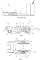
- Figure 2 shows a support roller arrangement 10 according to a first alternative of the present invention.
- the support roller arrangement 10 comprises a bogie 21 which comprises a pair of support rollers 22.1, 22.2 that are rotationally arranged in a bogie frame 23.
- the bogie frame 23 comprises first and second bogie frame sides 23.1, 23.2, which may be arranged parallel and be in the form of metal sheets or plates.
- the pair of support rollers 22.1, 22.2 is arranged in series, i.e. one roller in front of the other, between the bogie frame sides 23.1, 23.2.
- Each roller is rotationally attached to the bogie frame 23 by a respective roller pivot shaft 24.1, 24.2 that extends between the first bogie frame side 23.1 and the second bogie frame side 23.2 and through the respective roller (see figure 3 ).
- the roller support arrangement further comprises a bracket 30 for attaching the bogie 21 to a lift-truck 50.
- the bracket 30 comprises a front end to which the bogie 21 is pivotally is attached by the bogie pivot shaft 25.
- the bracket 30, may have a first and a second fork tine 31, 33 which extend on opposite sides of the bogie 21. The ends of the first and the second fork tines 31, 33 thereby constitute the front end of the bracket 30.
- the rear end of the bracket 30 is configured to be attached to the lift-truck 50.
- the rear end of the bracket 30 is configured to be attached to the underside of a ground supported load engagement of a lift truck not shown).
- a load engagement means may be in the form of ground supported lift-forks that are movable in vertical direction.
- the rear end of the bracket 30 is typically configured to be pivotally attached to underside of a ground supported load engagement means.
- the rear end of the bracket 30 may comprise diagonally spaced apart openings 35 that may be attached to pivot shafts on the underside of the ground supported load engagement means.
- the bracket 30, together with pivot shafts (not shown) between the load engagement means and the bogie 21 thereby forms a linkage which ensures that the pair of rollers 22.1, 22.2 remain in contact with the ground when the load engagement means 51.1, 52.1 moved vertically. This feature is known in the art and need not be described further here within.
- the bogie 21 is pivotally attached to the front end of the bracket 30.
- the bogie 21 comprises a bogie pivot shaft 25.
- the bogie pivot shaft 25 extends from the bogie frame 23 and is pivotally journalled in the front end of the bracket 30.
- the bogie pivot shaft 25 may be fixed to the bogie frame 23 such that the bogie 21 and the bogie pivot shaft 25 pivots relative the bracket 30.
- the bogie pivot shaft 25 comprises a first bogie pivot shaft section 25.1 and a second bogie pivot shaft section 25.2.
- the first bogie pivot shaft section 25.1 extends from the first bogie side frame 23.1 and is pivotally received in an opening 32 in the first fork tine 31.
- the second bogie pivot shaft section 25.2 extends from the second bogie frame side 23.2 and is pivotally received in an opening 34 in the second fork tine 33.
- the first and the second bogie pivot shaft sections 25.1, 25.2 are separate sections.
- the bogie pivot shaft 25 may also be realized as a single shaft.
- the first and second bogie pivot shaft sections 25.1, 25.2 extend respectively from a position between the first and the second roller. This facilitates a horizontal resting position of the bogie 21.
- the roller support arrangement comprises at least one spring device 40 which is coupled to the bogie 21 and to the bracket 30.
- the spring device 40 is configured to force or move the bogie 21 to a predetermined resting position.
- the spring device 40 is configured to force the bogie 21 from an inclined position, in which the orientation of the bogie 21 deviates from the resting position, to the resting position.
- the bogie 21 In the resting position, the bogie 21 may be level, i.e. oriented horizontally.
- the predetermined resting position may be relative a horizontal plane (X) and may be defined by the orientation of a longitudinal axis (A) that extends through the first and the second roller pivot shafts 24.1, 24.2 relative the horizontal plane (X).
- the spring device 40 is configured to force the bogie 21 to a resting position in which the bogie 21 is oriented parallel with the horizontal plane (since figure 2 is a plain side view, the horizontal plane is illustrated with a plain line). In the inclined position, the angular orientation of the bogie 21 (and the longitudinal axis (A) deviates from the horizontal plane (X).
- the spring device 40 is a torsion spring.
- the encircled area of figure 3 shows the spring device 40.
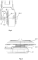
- Figure 4 shows an exploded view of the support roller arrangement 10 according to the first alternative of the present disclosure.
- the spring device 40 which may be manufactured of spring steel wire, comprises a coiled portion 41 and a first spring end 42.1 and a second spring end 42.2.
- the spring device may be dimensioned in view of the bogie in question. That is, in view of factors such as the dimensions and weight of the bogie and the pivoting distance back and forth from a resting position.
- a suitable spring device in the form of a torsion spring is available commercially from the company Lesjöfors AB under the article no: 7183: TSR 2,5X28X25X3.
- the coiled portion 41 is arranged around one of the bogie pivot shaft sections 25.1, 25.2, in this case the first bogie pivot shaft section 25.1.
- figure 5 which shows an enlarged view of the circled area of figure 3
- the first spring end 42.1 of the spring device 40 is coupled to the bogie 21, in this case attached to first bogie frame side 23.1.
- the second end 42.2 of the spring device 40 is coupled to the bracket 30, in this case attached to the first fork tine 31. Attachment of the ends 42.1, 42.2 of the spring device 40 may be achieved by bending the ends 42.1, 42.2 by e.g 90° and inserting them into appropriate openings in the bracket 30 and the bogie frame 23.
- a second spring device 40 in the form of a torsion spring, may be arranged around the second bogie pivot shaft section 25.2 and coupled by a first spring end 42.1 to the bogie 21, in this case the second bogie frame side 23.2, and by second spring end 42.2 to the bracket 30 in this case to the second fork tine 33. (this is not shown in the drawings).
- the bogie 21 may be forced to pivot in clockwise or anti-clock wise direction, for example as result of the bogie 21 climbing up on a pallet baseboard. Pivoting of the bogie 21 around the bogie pivot shaft 25 causes biasing of the spring device 40. When the bogie 21 loses the ground contact and no external forces acts on the bogie 21, the spring device relaxes from its biased state and forces the bogie 21 to pivot back to its resting position. Typically, in the resting position, no or small spring forces act on the bogie 21.
- FIG. 6 and 7 shows schematically a lift-truck 50 according to the present invention in operation of engaging a pallet.
- the lift-truck 50 may be a fork-lift truck, such as a powered pallet truck, powered stacker truck and low lifting order picking trucks.
- the lift-truck 50 comprises a first and a second vertically movable ground-supported load engagement means 51.1,51.2 in the form of a first and a second lifting fork arm (in figure 6 only load engagement means 51.1 is visible).
- the lift-truck 50 further comprises a housing 52.
- a drive wheel 53 is arranged underneath the housing 52.
- the housing 52 comprises a lifting/lowering arrangement 54 for raising or lowering the load engagement means 51.1, 51.2.
- the lifting/lowering arrangement 54 may comprise a hydraulic piston and cylinder coupled to the load engagement means 51.1, 52.1 and to hydraulic circuit including a hydraulic pump coupled to a motor (these features are not shown in detail).
- the housing 52 further comprises an electric motor 55 for propelling the drive wheel 53 of the lift-truck 50 and the hydraulic pump.
- the housing 52 further comprises an Electronic Control Unit (ECU) 56, for example a Programmable Logic Controller, which is configurable to control the motor 55 and the lifting/lowering arrangement 54 and other necessary functions of the lift-truck 50.
- the lift-truck 50 further comprises an operator's control 57 arranged on the housing 52 and other components (not shown) such as an electric battery and necessary electrical wiring, electronic circuits and hydraulic components as is known to the skilled person.
- the load engagement means 51.1, 52.2 extend from the front of the housing 52 and comprises each at least one support roller arrangement 10 according to the present invention for supporting the respective load engagement means 51.1, 52.2 on the ground surface that the lift-truck 50 is running on.
- the support roller arrangement 10 comprises, as described above a bracket 30 and a bogie 21 with a pair of support rollers 22.1, 22.2 that is attached in known manner, by a linkage (not shown), to the underside of the load engagement means 51.1, 52.2.
- Each load engagement means 51.1, 52.2 may further comprises a climbing wheel 58 which is arranged in front of the bogie 21.
- the load engagement means 51.1, 52.1 may further comprises a two auxiliary wheels 57 which are arranged behind the bogie 21.
- the climbing wheel 56, and the auxiliary wheels 59 are pivotally attached to shafts (not shown) to the lower side of the load engagement means 51.1, 52.2 and out of contact with the ground surface.
- the lift-truck 50 is in a position where the bogie 21 has started to climb up onto the baseboard of the pallet.
- the weight of the lift-truck 50 forces the bogie 21 to pivot such that the bogie 21 is inclined and may roll up onto the baseboard. Pivoting of the bogie 21 causes the biasing of the spring device as described hereinabove.
- the inclined orientation of the bogie 21 may remain in more or less degree until the bogie 21 has passed the baseboard and is out of contact with the underlying surface as shown in figure 7 . Since no forces now are acting on the bogie 21, the spring device 40 relaxes from its biased state and causes the bogie 21 to return to its horizontal resting position (see figure 7 ). The bogie 21 will then easily and without any impact roll over the next bas board of the pallet.
- figure 8 shows a roller support arrangement according to a second alternative of the present disclosure.
- the roller support arrangement according to the second alternative comprises a bogie 21 and a bracket 30 for attaching the bogie 21 to the load engagement means 51.1, 52.1 of a lift-truck 50.
- the spring device 40 is an extension spring having a coiled portion 41 and a first and a second spring end 42.1, 42.2.
- the first spring end 42.1 of the draw spring is coupled to the bogie, in this case the first bogie frame side 23.1
- the second end 42.2 of the draw spring is coupled to the bracket 30, in this case attached to the first fork tine 31.
- the draw spring In operation, when the bogie 21 is inclined during climbing, the draw spring will be biased by the pulling force from the bogie 21. When the bogie 21 loses ground contact the spring device 40 relaxes and forces the bogie 21 to pivot towards a predetermined resting position. Thus, if the bogie 21 is raised out of ground contact, the pulling force of the draw spring will force the bogie 21 to pivot back form an inclined position to its resting position (as shown in figures 6 and 7 ).
- FIG 9 shows a roller support arrangement according to a third alternative of the present invention.
- the roller support arrangement according to the third alternative comprises a bogie 21 and a bracket 30 for attaching the bogie 21 to the load engagement means 51.1, 52.1 of a lift-truck 50. These features are identical to the bogie 21 and bracket 30 as described under the first alternative.
- the spring device 40 is a torsion element arrangement.
- the torsion element arrangement comprises a first and a second resilient abutment bodies 43.1, 43.2 that are coupled to the bracket 30. In this case the abutment bodies 43.1, 43.2 are attached spaced apart in one of the openings for the bogie pivot shaft 25 in the rear end of the first fork tine 31.
- the abutment bodies 43.1, 43.2 may be made of rubber and may be in the form of cylinders.
- the torsion element arrangement further comprises an actuator 44 which is coupled to the bogie 21, in this case attached to the end of the bogie pivot shaft 25.
- the actuator 44 has a first end 42.1 which is attached to the end of the bogie pivot shaft 25 (not sown) and a second end 42.2 which extend in to the space between the first and the second abutment body 43.1, 43.2.
- the actuator 44 is configured such that, when the bogie 21 is in the predetermined resting position, the actuator 44 is in contact with the first and the second abutment body 43.1, 43.2 and exert the same force, or no force on the first and the second abutment body 43.1, 43.2.
- the actuator 44 rotates with the bogie pivot shaft 25 and exerts thereby a pressing force onto the abutment body 43.1, 43.2 that is in the pivoting direction of the bogie 21.
- the pair of rollers 22.1, 22.2 of the bogie 21 the is out of ground contact, in the abutment body 43.1, 43.2 will relax from its compressed, biased state and force the actuator 44 in counter direction and which causes the bogie 21 to pivot towards its resting position.
Landscapes
- Engineering & Computer Science (AREA)
- Transportation (AREA)
- Mechanical Engineering (AREA)
- Structural Engineering (AREA)
- Chemical & Material Sciences (AREA)
- Combustion & Propulsion (AREA)
- Civil Engineering (AREA)
- Life Sciences & Earth Sciences (AREA)
- Geology (AREA)
- Handcart (AREA)
Description
- The present invention relates to a support roller arrangement for a lift truck wherein a spring device that is coupled to the bogie and to the bracket (30) and configured to force the bogie towards a predetermined resting position. It also relates to a lift truck comprising a support roller arrangement.
- Examples of support roller arrangements are disclosed in documents
CN 203 449 855 U ,EP 2 998 189 A1 ,DE 10 68 630 BUS 2 921 771 A ,WO 2016/053124 A1 andDE 299 11 310 U1 . - Powered Low Lifting Fork-Lift Trucks or Powered Pallet Trucks comprises a height adjustably fork which is supported on the ground by front support rollers. These trucks are typically used for moving loading pallets in warehouses. Such pallets are supported on the ground by lower baseboards that are arranged parallel and form two channel-like openings for receiving the forks of the pallet truck. Sometimes, it is not possible to maneuver the truck into a position where the forks may be inserted into the appropriate channels of the pallet and instead the pallet is engaged in a direction transverse to the base boards. The forks of the lift trucks are typically provided with support rollers that support the forks on the ground. These rollers may be arranged in a bogie that pivots in order to enable the rollers to climb up onto and over the baseboards of the pallet. Climbing wheels may further be provided to facilitate the entering of the forks through the pallet. A lift truck comprising climbing wheels and a support roller bogie is disclosed in
EP3251918 . - However, a problem related to the known lift truck is that the support roller bogie, when hanging in the air between two baseboards of a pallet may be in an inclined orientation. This situation is shown in
Figure 1 . A problem thereby is that when theforks 3 of thelift truck 1 proceeds through thepallet 4, the inclinedsupport roller bogie 2 may hit the followingbase board 5. This in turn causes negative effects such as noise, shocks and movement of thepallet 4. - Thus, it is an object of the present invention to provide a support roller arrangement for a lift truck that solves or mitigates at least one of the problems of the prior art.
- A further object of the present invention is to provide a support roller arrangement for a lift truck, which allows for smooth engagement between the forks of the lift truck and the pallet.
- Yet a further object of the present invention is to provide a support roller arrangement for a lift truck which is of robust and simple construction and that may be realized at a low cost.
- According to the present invention, at least one of these objects is met by a support roller arrangement according to the appended claims.
- The support roller arrangement according to the present invention provides an advantage in that the bogie is allowed to assume an inclined orientation when climbing up on a baseboard of a pallet. However, as soon as the bogie has passed the baseboard and loses contact therewith it is returned to a predetermined resting position, which may be selected such that the bogie does not hit the subsequent baseboard. This reduces or eliminates the risk that the bogie hits the subsequent baseboard as the forks of the lift-truck proceeds through the pallet. In all, the support roller arrangement provides for easy and smooth engagement of pallets in a direction transverse to baseboards.
- Alternatives are set out in the appended dependent claims.
- The present invention also relates to a fork lift truck comprising a support roller arrangement according to appended claims.
-
- Fig. 1:
- A lift truck with a support roller arrangement according to the prior-art.
- Fig. 2:
- A support roller arrangement according to a first alternative of the present invention in side-view.
- Fig. 3:
- A support roller arrangement according to the first alternative of the present invention in a view from above.
- Fig. 4:
- An exploded view of a support roller arrangement according to first alternative of the present invention.
- Fig. 5:
- An enlarged portion of the support roller arrangement of
Fig. 3 . - Fig. 6, 7:
- A lift truck according to the present disclosure engaging a pallet.
- Fig. 8:
- A support roller arrangement according to a second alternative of the present invention.
- Fig. 9:
- A support roller arrangement according to a third alternative of the present invention.
- The support roller arrangement according to the present invention will now be described more fully hereinafter. The support roller arrangement according to the present invention may however be embodied in many different forms and should not be construed as limited to the embodiments set forth herein. Rather, these embodiments are provided by way of example. The scope of the present invention is limited only by the appended claims.
- Same reference numbers refer to same elements throughout the description.
- Further, in following description, any references to direction or positions or orientation are in relation to a situation in which the
support roller arrangement 10 is mounted on the engagement means 51.1, 52.1 of alift truck 50 that positioned on a horizontal ground surface. -
Figure 2 shows asupport roller arrangement 10 according to a first alternative of the present invention. - The
support roller arrangement 10 comprises abogie 21 which comprises a pair of support rollers 22.1, 22.2 that are rotationally arranged in abogie frame 23. Turning tofigure 3 , thebogie frame 23 comprises first and second bogie frame sides 23.1, 23.2, which may be arranged parallel and be in the form of metal sheets or plates. Returning tofigure 2 , the pair of support rollers 22.1, 22.2 is arranged in series, i.e. one roller in front of the other, between the bogie frame sides 23.1, 23.2. Each roller is rotationally attached to thebogie frame 23 by a respective roller pivot shaft 24.1, 24.2 that extends between the first bogie frame side 23.1 and the second bogie frame side 23.2 and through the respective roller (seefigure 3 ). - The roller support arrangement further comprises a
bracket 30 for attaching thebogie 21 to a lift-truck 50. - The
bracket 30 comprises a front end to which thebogie 21 is pivotally is attached by thebogie pivot shaft 25. Turning tofigure 3 , thebracket 30, may have a first and asecond fork tine bogie 21. The ends of the first and the second fork tines 31, 33 thereby constitute the front end of thebracket 30. Turning tofigure 2 , the rear end of thebracket 30 is configured to be attached to the lift-truck 50. Typically, the rear end of thebracket 30 is configured to be attached to the underside of a ground supported load engagement of a lift truck not shown). Such a load engagement means may be in the form of ground supported lift-forks that are movable in vertical direction. The rear end of thebracket 30 is typically configured to be pivotally attached to underside of a ground supported load engagement means. For this purpose, the rear end of thebracket 30 may comprise diagonally spaced apartopenings 35 that may be attached to pivot shafts on the underside of the ground supported load engagement means. Thebracket 30, together with pivot shafts (not shown) between the load engagement means and thebogie 21 thereby forms a linkage which ensures that the pair of rollers 22.1, 22.2 remain in contact with the ground when the load engagement means 51.1, 52.1 moved vertically. This feature is known in the art and need not be described further here within. - The
bogie 21 is pivotally attached to the front end of thebracket 30. For this purpose, thebogie 21 comprises abogie pivot shaft 25. Thebogie pivot shaft 25 extends from thebogie frame 23 and is pivotally journalled in the front end of thebracket 30. Thebogie pivot shaft 25 may be fixed to thebogie frame 23 such that thebogie 21 and thebogie pivot shaft 25 pivots relative thebracket 30. In the alternative of thesupport roller arrangement 10 shown infigure 3 , thebogie pivot shaft 25 comprises a first bogie pivot shaft section 25.1 and a second bogie pivot shaft section 25.2. The first bogie pivot shaft section 25.1 extends from the first bogie side frame 23.1 and is pivotally received in anopening 32 in thefirst fork tine 31. The second bogie pivot shaft section 25.2 extends from the second bogie frame side 23.2 and is pivotally received in anopening 34 in thesecond fork tine 33. Infigure 4 , the first and the second bogie pivot shaft sections 25.1, 25.2 are separate sections. However, thebogie pivot shaft 25 may also be realized as a single shaft. Typically, the first and second bogie pivot shaft sections 25.1, 25.2 extend respectively from a position between the first and the second roller. This facilitates a horizontal resting position of thebogie 21. - According to the present invention, the roller support arrangement comprises at least one
spring device 40 which is coupled to thebogie 21 and to thebracket 30. Thespring device 40 is configured to force or move thebogie 21 to a predetermined resting position. In detail, thespring device 40 is configured to force thebogie 21 from an inclined position, in which the orientation of thebogie 21 deviates from the resting position, to the resting position. In the resting position, thebogie 21 may be level, i.e. oriented horizontally. In detail, the predetermined resting position may be relative a horizontal plane (X) and may be defined by the orientation of a longitudinal axis (A) that extends through the first and the second roller pivot shafts 24.1, 24.2 relative the horizontal plane (X). For example, as shown infigure 2 , thespring device 40 is configured to force thebogie 21 to a resting position in which thebogie 21 is oriented parallel with the horizontal plane (sincefigure 2 is a plain side view, the horizontal plane is illustrated with a plain line). In the inclined position, the angular orientation of the bogie 21 (and the longitudinal axis (A) deviates from the horizontal plane (X). - According to a first alternative of the present invention, the
spring device 40 is a torsion spring. The encircled area offigure 3 shows thespring device 40. -
Figure 4 , shows an exploded view of thesupport roller arrangement 10 according to the first alternative of the present disclosure. Thus, thespring device 40, which may be manufactured of spring steel wire, comprises a coiledportion 41 and a first spring end 42.1 and a second spring end 42.2. The spring device may be dimensioned in view of the bogie in question. That is, in view of factors such as the dimensions and weight of the bogie and the pivoting distance back and forth from a resting position. A suitable spring device in the form of a torsion spring is available commercially from the company Lesjöfors AB under the article no: 7183:TSR 2,5X28X25X3. - The coiled
portion 41, is arranged around one of the bogie pivot shaft sections 25.1, 25.2, in this case the first bogie pivot shaft section 25.1. Turning tofigure 5 , which shows an enlarged view of the circled area offigure 3 , the first spring end 42.1 of thespring device 40 is coupled to thebogie 21, in this case attached to first bogie frame side 23.1. The second end 42.2 of thespring device 40 is coupled to thebracket 30, in this case attached to thefirst fork tine 31. Attachment of the ends 42.1, 42.2 of thespring device 40 may be achieved by bending the ends 42.1, 42.2 by e.g 90° and inserting them into appropriate openings in thebracket 30 and thebogie frame 23. - It is appreciated that a
second spring device 40, in the form of a torsion spring, may be arranged around the second bogie pivot shaft section 25.2 and coupled by a first spring end 42.1 to thebogie 21, in this case the second bogie frame side 23.2, and by second spring end 42.2 to thebracket 30 in this case to thesecond fork tine 33. (this is not shown in the drawings). - In operation, the
bogie 21 may be forced to pivot in clockwise or anti-clock wise direction, for example as result of thebogie 21 climbing up on a pallet baseboard. Pivoting of thebogie 21 around thebogie pivot shaft 25 causes biasing of thespring device 40. When thebogie 21 loses the ground contact and no external forces acts on thebogie 21, the spring device relaxes from its biased state and forces thebogie 21 to pivot back to its resting position. Typically, in the resting position, no or small spring forces act on thebogie 21. -
Figure 6 and 7 shows schematically a lift-truck 50 according to the present invention in operation of engaging a pallet. Turning tofigure 6 , the lift-truck 50 may be a fork-lift truck, such as a powered pallet truck, powered stacker truck and low lifting order picking trucks. The lift-truck 50 comprises a first and a second vertically movable ground-supported load engagement means 51.1,51.2 in the form of a first and a second lifting fork arm (infigure 6 only load engagement means 51.1 is visible). The lift-truck 50 further comprises ahousing 52. Adrive wheel 53 is arranged underneath thehousing 52. Thehousing 52 comprises a lifting/loweringarrangement 54 for raising or lowering the load engagement means 51.1, 51.2. For example, the lifting/loweringarrangement 54 may comprise a hydraulic piston and cylinder coupled to the load engagement means 51.1, 52.1 and to hydraulic circuit including a hydraulic pump coupled to a motor (these features are not shown in detail). Thehousing 52 further comprises anelectric motor 55 for propelling thedrive wheel 53 of the lift-truck 50 and the hydraulic pump. Thehousing 52 further comprises an Electronic Control Unit (ECU) 56, for example a Programmable Logic Controller, which is configurable to control themotor 55 and the lifting/loweringarrangement 54 and other necessary functions of the lift-truck 50. The lift-truck 50 further comprises an operator'scontrol 57 arranged on thehousing 52 and other components (not shown) such as an electric battery and necessary electrical wiring, electronic circuits and hydraulic components as is known to the skilled person. - The load engagement means 51.1, 52.2 extend from the front of the
housing 52 and comprises each at least onesupport roller arrangement 10 according to the present invention for supporting the respective load engagement means 51.1, 52.2 on the ground surface that the lift-truck 50 is running on. Thesupport roller arrangement 10 comprises, as described above abracket 30 and abogie 21 with a pair of support rollers 22.1, 22.2 that is attached in known manner, by a linkage (not shown), to the underside of the load engagement means 51.1, 52.2. Each load engagement means 51.1, 52.2 may further comprises aclimbing wheel 58 which is arranged in front of thebogie 21. The load engagement means 51.1, 52.1 may further comprises a twoauxiliary wheels 57 which are arranged behind thebogie 21. Theclimbing wheel 56, and theauxiliary wheels 59 are pivotally attached to shafts (not shown) to the lower side of the load engagement means 51.1, 52.2 and out of contact with the ground surface. - In
figure 6 , the lift-truck 50 is in a position where thebogie 21 has started to climb up onto the baseboard of the pallet. In this situation, the weight of the lift-truck 50 forces thebogie 21 to pivot such that thebogie 21 is inclined and may roll up onto the baseboard. Pivoting of thebogie 21 causes the biasing of the spring device as described hereinabove. The inclined orientation of thebogie 21 may remain in more or less degree until thebogie 21 has passed the baseboard and is out of contact with the underlying surface as shown infigure 7 . Since no forces now are acting on thebogie 21, thespring device 40 relaxes from its biased state and causes thebogie 21 to return to its horizontal resting position (seefigure 7 ). Thebogie 21 will then easily and without any impact roll over the next bas board of the pallet. - Although a particular embodiment has been disclosed in detail this has been done for purpose of illustration only, and is not intended to be limiting. In particular, it is contemplated that various substitutions, alterations and modifications may be made within the scope of the appended claims.
- For example,
figure 8 shows a roller support arrangement according to a second alternative of the present disclosure. The roller support arrangement according to the second alternative comprises abogie 21 and abracket 30 for attaching thebogie 21 to the load engagement means 51.1, 52.1 of a lift-truck 50. These features are identical to thebogie 21 andbracket 30 as described under the first alternative. However, according to the second the alternative of the present invention, thespring device 40 is an extension spring having a coiledportion 41 and a first and a second spring end 42.1, 42.2. The first spring end 42.1 of the draw spring is coupled to the bogie, in this case the first bogie frame side 23.1, The second end 42.2 of the draw spring is coupled to thebracket 30, in this case attached to thefirst fork tine 31. In operation, when thebogie 21 is inclined during climbing, the draw spring will be biased by the pulling force from thebogie 21. When thebogie 21 loses ground contact thespring device 40 relaxes and forces thebogie 21 to pivot towards a predetermined resting position. Thus, if thebogie 21 is raised out of ground contact, the pulling force of the draw spring will force thebogie 21 to pivot back form an inclined position to its resting position (as shown infigures 6 and 7 ). -
Figure 9 shows a roller support arrangement according to a third alternative of the present invention. The roller support arrangement according to the third alternative comprises abogie 21 and abracket 30 for attaching thebogie 21 to the load engagement means 51.1, 52.1 of a lift-truck 50. These features are identical to thebogie 21 andbracket 30 as described under the first alternative. However, according to the third the alternative of the present invention, thespring device 40 is a torsion element arrangement. The torsion element arrangement comprises a first and a second resilient abutment bodies 43.1, 43.2 that are coupled to thebracket 30. In this case the abutment bodies 43.1, 43.2 are attached spaced apart in one of the openings for thebogie pivot shaft 25 in the rear end of thefirst fork tine 31. The abutment bodies 43.1, 43.2 may be made of rubber and may be in the form of cylinders. The torsion element arrangement further comprises anactuator 44 which is coupled to thebogie 21, in this case attached to the end of thebogie pivot shaft 25. Theactuator 44 has a first end 42.1 which is attached to the end of the bogie pivot shaft 25 (not sown) and a second end 42.2 which extend in to the space between the first and the second abutment body 43.1, 43.2. Theactuator 44 is configured such that, when thebogie 21 is in the predetermined resting position, theactuator 44 is in contact with the first and the second abutment body 43.1, 43.2 and exert the same force, or no force on the first and the second abutment body 43.1, 43.2. However, when thebogie 21 is inclined, theactuator 44 rotates with thebogie pivot shaft 25 and exerts thereby a pressing force onto the abutment body 43.1, 43.2 that is in the pivoting direction of thebogie 21. As soon as the pair of rollers 22.1, 22.2 of thebogie 21 the is out of ground contact, in the abutment body 43.1, 43.2 will relax from its compressed, biased state and force theactuator 44 in counter direction and which causes thebogie 21 to pivot towards its resting position.
Claims (7)
- A support roller arrangement (10) for a lift truck (50) comprising:- a bogie (21) with a pair of support rollers (22.1, 22.2);- a bracket (30) for attaching the bogie (21) to a lift truck (50), wherein the bogie (21) is pivotally attached to the bracket (30), wherein a spring device (40) that is coupled to the bogie (21) and to the bracket (30) and configured to force the bogie (21) towards a predetermined resting position (A) characterized in thatthe spring device (40) is a coiled wire spring with a coiled portion (41) and a first end (42.1) that is attached to the bogie (21) and a second end (42.2) that is attached to the bracket (30).
- The support roller arrangement (10) according to claim 1, wherein the bogie (21) comprises a bogie frame (23) and wherein the support rollers (22.1, 22.2) are rotatable arranged in the bogie frame (23).
- The support roller arrangement (10) according to claim 1 or 2, wherein the bogie (21) is pivotally attached to the bracket (30) by a bogie pivot shaft (25).
- The support roller arrangement (10) according to anyone of claims 1 - 3, wherein the bracket (30) comprises a first fork tine (31) and a second fork tine (33) and wherein the bogie (21) is attached to the first fork tine (31) by a first bogie pivot shaft section (25.1) and to the second fork tine (33) by a second bogie pivot shaft section (25.2).
- The support roller arrangement (10) according to anyone one of claim 1 - 4, wherein the spring device (40) is a torsion spring.
- The support roller arrangement (10) according to claims 4 - 5 wherein the coiled portion (41) of the spring device (40) is arranged around a first or a second bogie pivot shaft section (25.1, 25.2) and wherein a first end (42.1) of the spring device (40) is attached to the bogie (21) and a second end (42.2) is attached to the bracket (30).
- A fork lift truck (50) having a first and a second height adjustable load engagement means (51.1, 52.1), characterized in that said first and a second height adjustable load engagement means (51.1, 52.1) respectively comprises a support roller arrangement (10) according to anyone of claims 1 - 6.
Applications Claiming Priority (1)
| Application Number | Priority Date | Filing Date | Title |
|---|---|---|---|
| SE2051073A SE544748C2 (en) | 2020-09-14 | 2020-09-14 | A support roller arrangement for a lift truck and a fork lift truck |
Publications (2)
| Publication Number | Publication Date |
|---|---|
| EP3967570A1 EP3967570A1 (en) | 2022-03-16 |
| EP3967570B1 true EP3967570B1 (en) | 2025-05-14 |
Family
ID=77738935
Family Applications (1)
| Application Number | Title | Priority Date | Filing Date |
|---|---|---|---|
| EP21196144.6A Active EP3967570B1 (en) | 2020-09-14 | 2021-09-10 | A support roller arrangement for a lift truck |
Country Status (3)
| Country | Link |
|---|---|
| EP (1) | EP3967570B1 (en) |
| CN (1) | CN114180493A (en) |
| SE (1) | SE544748C2 (en) |
Families Citing this family (1)
| Publication number | Priority date | Publication date | Assignee | Title |
|---|---|---|---|---|
| US12509338B2 (en) | 2024-03-27 | 2025-12-30 | Hyster-Yale Materials Handling, Inc. | Auxiliary rollers for a fork of a forked materials-handling vehicle |
Citations (1)
| Publication number | Priority date | Publication date | Assignee | Title |
|---|---|---|---|---|
| DE29911310U1 (en) * | 1999-06-29 | 2000-05-11 | Hannig, Tim, 38114 Braunschweig | Lifting vehicle |
Family Cites Families (12)
| Publication number | Priority date | Publication date | Assignee | Title |
|---|---|---|---|---|
| DE1068630B (en) * | 1958-05-21 | 1959-11-05 | ||
| US2178647A (en) * | 1938-03-25 | 1939-11-07 | Lyon Iron Works | Lift truck |
| US2921771A (en) * | 1957-09-19 | 1960-01-19 | Colson Corp | Pallet entry device |
| SE352868B (en) * | 1971-04-21 | 1973-01-15 | Bygg Och Transportekonomie Ab | |
| DE19615592B4 (en) * | 1996-04-19 | 2005-04-28 | Linde Ag | Pallet truck with a liftable load frame |
| DE102013100469A1 (en) * | 2012-10-15 | 2014-04-17 | Om Carrelli Elevatori S.P.A. | Industrial truck with load rollers arranged in pivoting load roller carriers |
| CN203449855U (en) * | 2013-06-03 | 2014-02-26 | 浙江中力机械有限公司 | Bearing wheel structure with high passing capability |
| SE539677C2 (en) * | 2014-09-19 | 2017-10-31 | Toyota Mat Handling Mfg Sweden Ab | Forklift truck and method for climbing an obstacle |
| PL231212B1 (en) * | 2014-09-30 | 2019-02-28 | Decylion Spolka Z Ograniczona Odpowiedzialnoscia | Servo-mechanism supporting movements on steep areas |
| CN104370244B (en) * | 2014-11-07 | 2017-04-05 | 诺力机械股份有限公司 | A kind of step type electric tray carriage |
| EP3251918B1 (en) | 2016-06-02 | 2019-03-06 | Toyota Material Handling Manufacturing Sweden AB | A lift-truck with automated climbing function |
| JP2018134958A (en) * | 2017-02-21 | 2018-08-30 | Kyb株式会社 | Lifting device |
-
2020
- 2020-09-14 SE SE2051073A patent/SE544748C2/en unknown
-
2021
- 2021-09-10 EP EP21196144.6A patent/EP3967570B1/en active Active
- 2021-09-13 CN CN202111068258.1A patent/CN114180493A/en active Pending
Patent Citations (1)
| Publication number | Priority date | Publication date | Assignee | Title |
|---|---|---|---|---|
| DE29911310U1 (en) * | 1999-06-29 | 2000-05-11 | Hannig, Tim, 38114 Braunschweig | Lifting vehicle |
Also Published As
| Publication number | Publication date |
|---|---|
| SE2051073A1 (en) | 2022-03-15 |
| CN114180493A (en) | 2022-03-15 |
| SE544748C2 (en) | 2022-11-01 |
| EP3967570A1 (en) | 2022-03-16 |
Similar Documents
| Publication | Publication Date | Title |
|---|---|---|
| US5890737A (en) | Pothole protection mechanism for a lifting device | |
| EP2159185B1 (en) | Industrial truck comprising two load carriages | |
| US9371217B1 (en) | Large wheeled, hand operated forklift | |
| EP2641862B1 (en) | Pedestrian-controlled highlifter | |
| US7165776B2 (en) | Pivotable tray for a pallet truck | |
| CN115744741B (en) | A stacker truck capable of carrying multiple goods | |
| US9994435B2 (en) | Forklift arrangement | |
| EP2805911B1 (en) | Industrial truck, in particular picking truck with a driver's cab that can be raised and lowered | |
| EP2825497B1 (en) | Order pickers | |
| US6220811B1 (en) | Apparatus and method for handling and transporting bales | |
| EP3967570A1 (en) | A support roller arrangement for a lift truck | |
| CN118973944A (en) | Unmanned conveyor with adjustable width | |
| CN113979362A (en) | Anti-tipping forklift structure | |
| US4268210A (en) | Pallet unloader for fork lifts | |
| US3672526A (en) | Front and side loading attachment for lifting trucks | |
| US9309096B2 (en) | Industrial truck with wheelarm lever system | |
| US5501297A (en) | Safety guard assembly for fork lift trucks | |
| KR20120015541A (en) | The lifting equipment for an automobil | |
| CA2564049A1 (en) | Forklift attachment utilizing plow mounts and frame | |
| EP3272699A1 (en) | Shelf stacker | |
| US6364060B1 (en) | Low profile lift assembly | |
| EP1322541A2 (en) | Two sided system for loading trucks | |
| EP1486393B1 (en) | A device for handling pallets | |
| KR20100133161A (en) | Hand Electric Pallet Feeder with Adjustable Fork Width | |
| KR101256847B1 (en) | Lifter for palette of cargo |
Legal Events
| Date | Code | Title | Description |
|---|---|---|---|
| PUAI | Public reference made under article 153(3) epc to a published international application that has entered the european phase |
Free format text: ORIGINAL CODE: 0009012 |
|
| STAA | Information on the status of an ep patent application or granted ep patent |
Free format text: STATUS: REQUEST FOR EXAMINATION WAS MADE |
|
| 17P | Request for examination filed |
Effective date: 20220201 |
|
| AK | Designated contracting states |
Kind code of ref document: A1 Designated state(s): AL AT BE BG CH CY CZ DE DK EE ES FI FR GB GR HR HU IE IS IT LI LT LU LV MC MK MT NL NO PL PT RO RS SE SI SK SM TR |
|
| STAA | Information on the status of an ep patent application or granted ep patent |
Free format text: STATUS: EXAMINATION IS IN PROGRESS |
|
| 17Q | First examination report despatched |
Effective date: 20221017 |
|
| P01 | Opt-out of the competence of the unified patent court (upc) registered |
Effective date: 20230523 |
|
| GRAP | Despatch of communication of intention to grant a patent |
Free format text: ORIGINAL CODE: EPIDOSNIGR1 |
|
| STAA | Information on the status of an ep patent application or granted ep patent |
Free format text: STATUS: GRANT OF PATENT IS INTENDED |
|
| INTG | Intention to grant announced |
Effective date: 20241115 |
|
| GRAJ | Information related to disapproval of communication of intention to grant by the applicant or resumption of examination proceedings by the epo deleted |
Free format text: ORIGINAL CODE: EPIDOSDIGR1 |
|
| STAA | Information on the status of an ep patent application or granted ep patent |
Free format text: STATUS: EXAMINATION IS IN PROGRESS |
|
| INTC | Intention to grant announced (deleted) | ||
| GRAS | Grant fee paid |
Free format text: ORIGINAL CODE: EPIDOSNIGR3 |
|
| STAA | Information on the status of an ep patent application or granted ep patent |
Free format text: STATUS: GRANT OF PATENT IS INTENDED |
|
| GRAP | Despatch of communication of intention to grant a patent |
Free format text: ORIGINAL CODE: EPIDOSNIGR1 |
|
| GRAA | (expected) grant |
Free format text: ORIGINAL CODE: 0009210 |
|
| STAA | Information on the status of an ep patent application or granted ep patent |
Free format text: STATUS: THE PATENT HAS BEEN GRANTED |
|
| INTG | Intention to grant announced |
Effective date: 20250402 |
|
| AK | Designated contracting states |
Kind code of ref document: B1 Designated state(s): AL AT BE BG CH CY CZ DE DK EE ES FI FR GB GR HR HU IE IS IT LI LT LU LV MC MK MT NL NO PL PT RO RS SE SI SK SM TR |
|
| REG | Reference to a national code |
Ref country code: GB Ref legal event code: FG4D |
|
| REG | Reference to a national code |
Ref country code: CH Ref legal event code: EP |
|
| REG | Reference to a national code |
Ref country code: IE Ref legal event code: FG4D |
|
| REG | Reference to a national code |
Ref country code: DE Ref legal event code: R096 Ref document number: 602021030715 Country of ref document: DE |
|
| REG | Reference to a national code |
Ref country code: SE Ref legal event code: TRGR |
|
| REG | Reference to a national code |
Ref country code: NL Ref legal event code: MP Effective date: 20250514 |
|
| PG25 | Lapsed in a contracting state [announced via postgrant information from national office to epo] |
Ref country code: FI Free format text: LAPSE BECAUSE OF FAILURE TO SUBMIT A TRANSLATION OF THE DESCRIPTION OR TO PAY THE FEE WITHIN THE PRESCRIBED TIME-LIMIT Effective date: 20250514 Ref country code: PT Free format text: LAPSE BECAUSE OF FAILURE TO SUBMIT A TRANSLATION OF THE DESCRIPTION OR TO PAY THE FEE WITHIN THE PRESCRIBED TIME-LIMIT Effective date: 20250915 Ref country code: ES Free format text: LAPSE BECAUSE OF FAILURE TO SUBMIT A TRANSLATION OF THE DESCRIPTION OR TO PAY THE FEE WITHIN THE PRESCRIBED TIME-LIMIT Effective date: 20250514 |
|
| PGFP | Annual fee paid to national office [announced via postgrant information from national office to epo] |
Ref country code: DE Payment date: 20250926 Year of fee payment: 5 |
|
| REG | Reference to a national code |
Ref country code: LT Ref legal event code: MG9D |
|
| PG25 | Lapsed in a contracting state [announced via postgrant information from national office to epo] |
Ref country code: GR Free format text: LAPSE BECAUSE OF FAILURE TO SUBMIT A TRANSLATION OF THE DESCRIPTION OR TO PAY THE FEE WITHIN THE PRESCRIBED TIME-LIMIT Effective date: 20250815 Ref country code: NO Free format text: LAPSE BECAUSE OF FAILURE TO SUBMIT A TRANSLATION OF THE DESCRIPTION OR TO PAY THE FEE WITHIN THE PRESCRIBED TIME-LIMIT Effective date: 20250814 |
|
| PG25 | Lapsed in a contracting state [announced via postgrant information from national office to epo] |
Ref country code: PL Free format text: LAPSE BECAUSE OF FAILURE TO SUBMIT A TRANSLATION OF THE DESCRIPTION OR TO PAY THE FEE WITHIN THE PRESCRIBED TIME-LIMIT Effective date: 20250514 Ref country code: NL Free format text: LAPSE BECAUSE OF FAILURE TO SUBMIT A TRANSLATION OF THE DESCRIPTION OR TO PAY THE FEE WITHIN THE PRESCRIBED TIME-LIMIT Effective date: 20250514 |
|
| PGFP | Annual fee paid to national office [announced via postgrant information from national office to epo] |
Ref country code: IT Payment date: 20250922 Year of fee payment: 5 |
|
| REG | Reference to a national code |
Ref country code: AT Ref legal event code: MK05 Ref document number: 1794578 Country of ref document: AT Kind code of ref document: T Effective date: 20250514 |
|
| PG25 | Lapsed in a contracting state [announced via postgrant information from national office to epo] |
Ref country code: BG Free format text: LAPSE BECAUSE OF FAILURE TO SUBMIT A TRANSLATION OF THE DESCRIPTION OR TO PAY THE FEE WITHIN THE PRESCRIBED TIME-LIMIT Effective date: 20250514 |
|
| PGFP | Annual fee paid to national office [announced via postgrant information from national office to epo] |
Ref country code: GB Payment date: 20250923 Year of fee payment: 5 |
|
| PG25 | Lapsed in a contracting state [announced via postgrant information from national office to epo] |
Ref country code: HR Free format text: LAPSE BECAUSE OF FAILURE TO SUBMIT A TRANSLATION OF THE DESCRIPTION OR TO PAY THE FEE WITHIN THE PRESCRIBED TIME-LIMIT Effective date: 20250514 |
|
| PG25 | Lapsed in a contracting state [announced via postgrant information from national office to epo] |
Ref country code: AT Free format text: LAPSE BECAUSE OF FAILURE TO SUBMIT A TRANSLATION OF THE DESCRIPTION OR TO PAY THE FEE WITHIN THE PRESCRIBED TIME-LIMIT Effective date: 20250514 |
|
| PGFP | Annual fee paid to national office [announced via postgrant information from national office to epo] |
Ref country code: FR Payment date: 20250925 Year of fee payment: 5 |
|
| PGFP | Annual fee paid to national office [announced via postgrant information from national office to epo] |
Ref country code: SE Payment date: 20250924 Year of fee payment: 5 |
|
| PG25 | Lapsed in a contracting state [announced via postgrant information from national office to epo] |
Ref country code: RS Free format text: LAPSE BECAUSE OF FAILURE TO SUBMIT A TRANSLATION OF THE DESCRIPTION OR TO PAY THE FEE WITHIN THE PRESCRIBED TIME-LIMIT Effective date: 20250814 |
|
| PG25 | Lapsed in a contracting state [announced via postgrant information from national office to epo] |
Ref country code: IS Free format text: LAPSE BECAUSE OF FAILURE TO SUBMIT A TRANSLATION OF THE DESCRIPTION OR TO PAY THE FEE WITHIN THE PRESCRIBED TIME-LIMIT Effective date: 20250914 |
|
| PG25 | Lapsed in a contracting state [announced via postgrant information from national office to epo] |
Ref country code: LV Free format text: LAPSE BECAUSE OF FAILURE TO SUBMIT A TRANSLATION OF THE DESCRIPTION OR TO PAY THE FEE WITHIN THE PRESCRIBED TIME-LIMIT Effective date: 20250514 |
|
| PG25 | Lapsed in a contracting state [announced via postgrant information from national office to epo] |
Ref country code: DK Free format text: LAPSE BECAUSE OF FAILURE TO SUBMIT A TRANSLATION OF THE DESCRIPTION OR TO PAY THE FEE WITHIN THE PRESCRIBED TIME-LIMIT Effective date: 20250514 Ref country code: SM Free format text: LAPSE BECAUSE OF FAILURE TO SUBMIT A TRANSLATION OF THE DESCRIPTION OR TO PAY THE FEE WITHIN THE PRESCRIBED TIME-LIMIT Effective date: 20250514 |
|
| PG25 | Lapsed in a contracting state [announced via postgrant information from national office to epo] |
Ref country code: CZ Free format text: LAPSE BECAUSE OF FAILURE TO SUBMIT A TRANSLATION OF THE DESCRIPTION OR TO PAY THE FEE WITHIN THE PRESCRIBED TIME-LIMIT Effective date: 20250514 |
|
| PG25 | Lapsed in a contracting state [announced via postgrant information from national office to epo] |
Ref country code: EE Free format text: LAPSE BECAUSE OF FAILURE TO SUBMIT A TRANSLATION OF THE DESCRIPTION OR TO PAY THE FEE WITHIN THE PRESCRIBED TIME-LIMIT Effective date: 20250514 |
|
| PG25 | Lapsed in a contracting state [announced via postgrant information from national office to epo] |
Ref country code: RO Free format text: LAPSE BECAUSE OF FAILURE TO SUBMIT A TRANSLATION OF THE DESCRIPTION OR TO PAY THE FEE WITHIN THE PRESCRIBED TIME-LIMIT Effective date: 20250514 Ref country code: SK Free format text: LAPSE BECAUSE OF FAILURE TO SUBMIT A TRANSLATION OF THE DESCRIPTION OR TO PAY THE FEE WITHIN THE PRESCRIBED TIME-LIMIT Effective date: 20250514 |
|
| REG | Reference to a national code |
Ref country code: DE Ref legal event code: R097 Ref document number: 602021030715 Country of ref document: DE |
|
| PLBE | No opposition filed within time limit |
Free format text: ORIGINAL CODE: 0009261 |
|
| STAA | Information on the status of an ep patent application or granted ep patent |
Free format text: STATUS: NO OPPOSITION FILED WITHIN TIME LIMIT |
|
| REG | Reference to a national code |
Ref country code: CH Ref legal event code: L10 Free format text: ST27 STATUS EVENT CODE: U-0-0-L10-L00 (AS PROVIDED BY THE NATIONAL OFFICE) Effective date: 20260325 |
|
| 26N | No opposition filed |
Effective date: 20260217 |
|
| REG | Reference to a national code |
Ref country code: CH Ref legal event code: H13 Free format text: ST27 STATUS EVENT CODE: U-0-0-H10-H13 (AS PROVIDED BY THE NATIONAL OFFICE) Effective date: 20260504 |
|
| PG25 | Lapsed in a contracting state [announced via postgrant information from national office to epo] |
Ref country code: LU Free format text: LAPSE BECAUSE OF NON-PAYMENT OF DUE FEES Effective date: 20250910 |
|
| REG | Reference to a national code |
Ref country code: BE Ref legal event code: MM Effective date: 20250930 |
|
| PG25 | Lapsed in a contracting state [announced via postgrant information from national office to epo] |
Ref country code: LT Free format text: LAPSE BECAUSE OF FAILURE TO SUBMIT A TRANSLATION OF THE DESCRIPTION OR TO PAY THE FEE WITHIN THE PRESCRIBED TIME-LIMIT Effective date: 20250514 |
|
| PG25 | Lapsed in a contracting state [announced via postgrant information from national office to epo] |
Ref country code: MC Free format text: LAPSE BECAUSE OF FAILURE TO SUBMIT A TRANSLATION OF THE DESCRIPTION OR TO PAY THE FEE WITHIN THE PRESCRIBED TIME-LIMIT Effective date: 20250514 |
|
| PG25 | Lapsed in a contracting state [announced via postgrant information from national office to epo] |
Ref country code: IE Free format text: LAPSE BECAUSE OF NON-PAYMENT OF DUE FEES Effective date: 20250910 Ref country code: CH Free format text: LAPSE BECAUSE OF NON-PAYMENT OF DUE FEES Effective date: 20250930 Ref country code: BE Free format text: LAPSE BECAUSE OF NON-PAYMENT OF DUE FEES Effective date: 20250930 |