EP3967564A1 - Method for adjusting the speed of a vehicle - Google Patents
Method for adjusting the speed of a vehicle Download PDFInfo
- Publication number
- EP3967564A1 EP3967564A1 EP20196131.5A EP20196131A EP3967564A1 EP 3967564 A1 EP3967564 A1 EP 3967564A1 EP 20196131 A EP20196131 A EP 20196131A EP 3967564 A1 EP3967564 A1 EP 3967564A1
- Authority
- EP
- European Patent Office
- Prior art keywords
- ego
- vehicle
- target
- speed
- control profile
- Prior art date
- Legal status (The legal status is an assumption and is not a legal conclusion. Google has not performed a legal analysis and makes no representation as to the accuracy of the status listed.)
- Granted
Links
Images


Classifications
-
- B—PERFORMING OPERATIONS; TRANSPORTING
- B60—VEHICLES IN GENERAL
- B60W—CONJOINT CONTROL OF VEHICLE SUB-UNITS OF DIFFERENT TYPE OR DIFFERENT FUNCTION; CONTROL SYSTEMS SPECIALLY ADAPTED FOR HYBRID VEHICLES; ROAD VEHICLE DRIVE CONTROL SYSTEMS FOR PURPOSES NOT RELATED TO THE CONTROL OF A PARTICULAR SUB-UNIT
- B60W30/00—Purposes of road vehicle drive control systems not related to the control of a particular sub-unit, e.g. of systems using conjoint control of vehicle sub-units
- B60W30/14—Adaptive cruise control
- B60W30/143—Speed control
-
- B—PERFORMING OPERATIONS; TRANSPORTING
- B60—VEHICLES IN GENERAL
- B60W—CONJOINT CONTROL OF VEHICLE SUB-UNITS OF DIFFERENT TYPE OR DIFFERENT FUNCTION; CONTROL SYSTEMS SPECIALLY ADAPTED FOR HYBRID VEHICLES; ROAD VEHICLE DRIVE CONTROL SYSTEMS FOR PURPOSES NOT RELATED TO THE CONTROL OF A PARTICULAR SUB-UNIT
- B60W30/00—Purposes of road vehicle drive control systems not related to the control of a particular sub-unit, e.g. of systems using conjoint control of vehicle sub-units
- B60W30/18—Propelling the vehicle
- B60W30/18009—Propelling the vehicle related to particular drive situations
- B60W30/18163—Lane change; Overtaking manoeuvres
-
- G—PHYSICS
- G08—SIGNALLING
- G08G—TRAFFIC CONTROL SYSTEMS
- G08G1/00—Traffic control systems for road vehicles
- G08G1/09—Arrangements for giving variable traffic instructions
- G08G1/0962—Arrangements for giving variable traffic instructions having an indicator mounted inside the vehicle, e.g. giving voice messages
- G08G1/09623—Systems involving the acquisition of information from passive traffic signs by means mounted on the vehicle
-
- G—PHYSICS
- G08—SIGNALLING
- G08G—TRAFFIC CONTROL SYSTEMS
- G08G1/00—Traffic control systems for road vehicles
- G08G1/22—Platooning, i.e. convoy of communicating vehicles
-
- B—PERFORMING OPERATIONS; TRANSPORTING
- B60—VEHICLES IN GENERAL
- B60W—CONJOINT CONTROL OF VEHICLE SUB-UNITS OF DIFFERENT TYPE OR DIFFERENT FUNCTION; CONTROL SYSTEMS SPECIALLY ADAPTED FOR HYBRID VEHICLES; ROAD VEHICLE DRIVE CONTROL SYSTEMS FOR PURPOSES NOT RELATED TO THE CONTROL OF A PARTICULAR SUB-UNIT
- B60W2720/00—Output or target parameters relating to overall vehicle dynamics
- B60W2720/10—Longitudinal speed
- B60W2720/103—Speed profile
Definitions
- the present invention relates to a first method for adjusting the speed of a vehicle. Further, the invention relates to a method for adjusting the position of the vehicle by executing the first method. Finally, the invention relates to a device, a system, a vehicle, a computer programme product and a storage medium.
- autonomous vehicles are understood to be those that are configured in particular to execute the methods that are the subject-matters of the invention.
- an autonomous vehicle is also a vehicle, that is configured only to execute the method according to the invention.
- autonomous vehicles can be understood to be configured to drive partially or fully autonomous.
- Autonomous driving is a huge field for automotive development. Vehicles must interact with other traffic participants such as other autonomous or non-autonomous vehicles and take other constraints such as obstacles, pedestrians, speed limits, etc. into account.
- One part of this field relates to the adjusting of the speed of an autonomous vehicle. To reach a target speed from an initial speed several speed profiles are possible. Further, if the vehicle tries to reach a target position relative to another traffic participant it has to adjust its speed to reach this target position. For example, this target position is a position within or at the end of a platoon of several vehicles. However, the target position can be a starting position for a lane change as well. Therefore, there is a need for adjusting the speed of a vehicle and in particular for leading a vehicle into a target position.
- a method for adjusting the speed of a vehicle that is moving with an initial speed, to a target speed comprising the steps:
- the vehicle is comprising a speed control system that is configured to receive at least one control parameter, in particular a target value, and to adjust the speed of the vehicle in reaction to the control parameter.
- a speed control system configured to receive at least one control parameter, in particular a target value, and to adjust the speed of the vehicle in reaction to the control parameter.
- the control parameter of the control profile is comprising a target value for the vehicle, wherein the vehicle is configured to reach the target value.
- the target value is comprising a target acceleration value or a target acceleration profile, and/or a target speed value or a target speed profile, and/or a target force or target torque value or a target force or target torque profile, and/or a target engine load value or a target engine load profile, and/or a target brake demand value or a target brake demand profile. If at least one of these parameters is supplied to the speed control system of the vehicle, the vehicle will preferably react by its speed control system to reach the corresponding target value or profile.
- one control profile part is comprising exclusively a control parameter causing an acceleration or a deceleration of the vehicle, wherein preferably, when the control profile consists of two control profile parts, one of the two control profile parts is comprising exclusively control parameter causing an acceleration and the other of the two control profile parts causing a deceleration.
- the control profile is comprising a target acceleration
- one control profile part can exclusively comprise positive or negative target acceleration values.
- the control profile is comprising a target speed
- the control profile part causing an acceleration of the vehicle can comprise ascending speed values
- the control profile part causing a deceleration of the vehicle can comprise descending speed values.
- control profile is comprising a switching point separating two control profile parts of the control profile from each other.
- switching point is dividing the control profile into two control profile parts.
- the two control profile parts can comprise the same length, but in general do not need to have the same length.
- control profile is comprising an end point defining the end of the control profile and when the end point is reached the speed of the vehicle is preferably equal to the target speed.
- the switching point and/or the end point are preferably determined during the determining of the control profile.
- each control profile part can cause a constant acceleration and/or deceleration.
- one of the two control profile parts can cause an acceleration and the other one a deceleration of the vehicle.
- These two control profile parts can be adjacent within the control profile.
- At least one of the control profile parts is causing a linear adjusting of the speed, wherein preferably, the control profile is causing exclusively a linear adjusting of the speed. That means that the adjusting of the speed is executed under constant acceleration and/or deceleration.
- the control profile is comprising a target acceleration profile
- the corresponding control profile part can comprise a constant acceleration value.
- the corresponding control profile part can comprise a linear speed profile.
- the control profile is based on time and/or speed of the vehicle and/or distance of the vehicle. If the control profile is based on time, the switching point and/or the end point can be defined as special points of time within the control profile. If the control profile is based on speed, the switching point and/or the end point can be defined by a special speed value. In this case the end point can be a speed with respect to another vehicle, in particular the speed of the other vehicle. If the control profile is based on distance, the switching point and/or the end point can be defined as special points along the driveway of the vehicle. In this case the end point can be a position with respect to another vehicle.
- a method for leading a vehicle that is moving on a lane into a target position with respect to at least one other vehicle comprising the steps:
- the end point of the control profile can also be the target position.
- the target position and/or the current position are longitudinal positions with respect to the direction of travel of the vehicle.
- This method can be used to adjust the position of the vehicle with respect to at least one other vehicle by adjusting the speed of the vehicle by the execution of the method as described above, wherein the control profile is determined and applied to the vehicle.
- the method for adjusting the speed as described above is only executed if the current position of the vehicle is not equal to the target position.
- the control profile is determined in such way that the speed of the vehicle is equal to the target speed when reaching the target position.
- the method is used to close a gap between the vehicle and another vehicle that is the last vehicle of a platoon, the vehicle reaches the target position, which is a position behind the other vehicle, with the same speed as the other vehicle. Therefore, the vehicle can be integrated into the platoon by reaching the target position.
- the method is used to lead the vehicle in a position with respect to another vehicle moving on an adjacent line. This position can be a starting position for a lane change, which can be defined by a safety distance with respect to the other vehicle, wherein the vehicle has to reach this safety distance before starting the lane change manoeuvre.
- the starting position can be in front or behind the other vehicle. Further, more than just one vehicle can be taken into account to determine the starting position, for example the starting position is determined by a gap between two vehicles moving behind each other on a lane adjacent to the lane where the vehicle is moving.
- At least one other vehicle or the at least one other vehicle is moving in front of the vehicle or behind the vehicle or on an adjacent lane.
- one of the methods above is comprising a step wherein determining the target speed from an external source is executed.
- the external source is a traffic sign and/or a digital source and/or the speed of at least one other vehicle.
- a digital source a speed limit from digital map data can be used. If the speed of the vehicle shall be adjusted to the speed of another vehicle, the target speed can be determined from the speed of the other vehicle.
- the target speed is determined by the use of a detection means, in particular a camera, a radar sensor, a GPS-receiver, a radio receiver.
- control profile in particular at least one control profile part is determined under consideration of time optimal, wear optimal and/or energy optimal aspects.
- the invention models the preparation for a lane change, in which the vehicle intends to merge into an adjacent lane which has traffic moving with a certain speed and distance between the vehicles.
- the following initial parameters are taking into account: the speed of the vehicle, the speed of the vehicles in the adjacent target lane, the distance of vehicles in adjacent lane, and the longitudinal offset distance between the vehicle and the closest vehicle in the adjacent lane.
- the vehicle aims to reach the point at which it can perform a safe lane change into that target lane.
- its speed must be the same as the vehicles in the target lane
- its longitudinal offset must be in between two vehicles or at least at a safe distance from the preceding and the following vehicle.
- the total time which this preparation for a lane change takes is modelled into two control profile parts, each of which has the same constant acceleration, but with opposite sign.
- This two-split preparation allows that the vehicle can reach the conditions for a safe lane change from any combination of the initial conditions.
- This simple model allows to formulate a relation between the following variables: vehicle acceleration, the total lane change preparation time and the time instance where the sign of the acceleration swaps (the switching point separating the total control profile into two control profile parts).
- the total duration of the preparation phase depends on the initial conditions as well as on the selected acceleration.
- the mathematical relation between these variables and parameters allows judgement if the lane change preparation is completed within a given time, considering limited lane change length and limited vehicle acceleration capabilities.
- the algorithm allows to select an acceleration which is optimal under certain conditions, e.g. regarding fuel efficiency, shortest possible time, or other criteria.
- the approach can also indicate which of the vehicle gaps in the moving traffic lane provides the best possible gap in between two vehicles moving on the target lane, where the vehicle can merge, again depending on its capabilities and boundary conditions. If there is no limit on the merging distance, then the preparation of the control profile with several control profile parts can default into a single time period with a constant acceleration, after which the vehicle is in the proper location for performing the lane change.
- a device for executing a method as described above comprising:
- the interface can supply the control profile directly to the speed control system of the vehicle.
- the control means is preferably comprising an electronic control unit, like an ECU. Therefore, by providing the device in the vehicle, the vehicle can be configured for executing the method according to the invention.
- a system comprising:
- a vehicle in particular an autonomous vehicle, is provided comprising a device as described above or a system as described above.
- the vehicle is configured to execute the method as described above in another way.
- a computer program product comprising code means configured to cause a device, in particular a device as described above, to execute the method as described above.
- a storage medium comprising a computer program product as described above.
- the invention allows to adjust the speed of the vehicle and in addition its position with respect to another vehicle.
- This can be used for a driver assistance system or a fully autonomously driving vehicle.
- the invention can determine a feasibility for a lane change from initial conditions like the speed of the vehicle, of at least one other vehicle and of their distances with respect to each other.
- the invention can provide the time after which the adjusting of the speed is finished.
- Fig. 1 shows a traffic situation seen from above for the executing of the method according to the invention.
- Two lanes L 1 , L 2 are shown in the drawing, extending from the left to the right and being parallel and adjacent to each other.
- traffic is moving on both lanes L 1 , L 2 from the left to the right.
- a vehicle EGO moves on the lane L 1 with a speed v ego, 0 from the left to the right.
- the vehicle EGO is configured to adjust its speed by a speed control system according to a control parameter that can be supplied to the speed control system of the vehicle EGO.
- On lane L 2 four vehicles 1, 2, 3, 4 are moving with a speed v L . Between the vehicles 1, 2, 3, 4 there are gaps d L, 12 , d L, 23 , d L , 34.
- the vehicle EGO has a current or initial position d 0, ego with reference to vehicle 2.
- the vehicles 1, 2, 3, 4 can for example form a platoon.
- the lane L 1 where the vehicle EGO is moving is limited in its extension to the right.
- lane L 1 is a merging lane. Therefore, the vehicle EGO needs to change to lane L 2 by a lane change manoeuvre.
- the vehicle EGO before the vehicle EGO can execute the lane change manoeuvre, it has to adjust its position and its speed with reference to the vehicles 1, 2, 3, 4 moving already on lane L 2 , to reach an initial state the vehicle EGO must have for the lane change manoeuvre.
- the vehicle EGO it is an object to get the vehicle EGO into a position on lane L 1 with respect to at least one of the vehicles 1, 2, 3, 4 that the vehicle EGO can start a lane change manoeuvre in order to change from lane L 1 to L 2 .
- the speed of the vehicle EGO has to be adjusted in such way that a lane change manoeuvre can be started. Therefore, the speed of the vehicle EGO must not be too slow or too fast.
- the speed of the vehicle EGO should be equal to the speed v L of the vehicles 1, 2, 3, 4 or at least within the same scale.
- the ending of the lane L 1 has to be considered by the method.
- a control profile comprising at least one control parameter allowing adjusting the speed of the vehicle EGO to a target speed.
- the target speed can be determined as stated above, from the speed v L of the vehicles 1, 2, 3, 4.
- the control parameter can comprise a target profile or value, that is supplied to the speed control system of the vehicle EGO.
- the control parameter comprises a target value as described above.
- a switching point T 1 is shown, which is determined as a part of the control profile.
- the switching point is a point of time, whereby two control profile parts are separated.
- an end point T m is shown, which is determined as a part of the control profile.
- the end point is a point of time, whereby the ending of the control profile and its duration is defined.
- both control profile parts can be configured to cause exclusively acceleration of the vehicle EGO during the executing one of both control profile parts, wherein during executing of the other control profile part exclusively deceleration of the vehicle EGO is caused.
- the time is set for adjusting the distance d 0, ego to the distance needed to join the platoon and for adjusting the speed of the vehicle EGO to a corresponding speed.
- Fig. 2 shows another traffic situation seen from above for the executing of the method according to the invention.
- a vehicle EGO is shown which corresponds to the vehicle EGO of Fig. 1 .
- the vehicle EGO is moving with its speed v ego, 0 from the left to the right on a lane L 3 which is extending from the left to the right.
- the vehicle EGO is approaching to several vehicles 1, 2, 3, 4 moving in front of the vehicle EGO, wherein the vehicles 1, 2, 3, 4 are moving with a speed v L on the same lane L 3 .
- the vehicles 1, 2, 3, 4 can, for example, act as a platoon as shown in Fig. 1 .
- the vehicle EGO is in an initial position d 0, ego with reference to the vehicle 1.
- a time axis t and an axis indicating the distance s(t) are shown, wherein the axis indicating the distance s(t) corresponds to the distance the vehicle EGO moves from left to right.
- the vehicle EGO can be an object to get the vehicle EGO into a position on lane L 3 with respect to at least one of the vehicles 1, 2, 3, 4, in particular to vehicle 1, wherein the vehicle EGO can join the platoon of the vehicles 1, 2, 3, 4.
- the speed of the vehicle EGO has to be adjusted in such way, that no safety critical situation appears on the one hand and that on the other hand the vehicle EGO can reduce the distance to the vehicle 1 indeed. Therefore, the speed of the vehicle EGO in the target position behind vehicle 1 must not be too slow or too fast.
- the speed of the vehicle EGO should be equal to the speed v L of the vehicles 1, 2, 3, 4 or at least within the same scale.
- a control profile comprising at least one control parameter allowing adjusting the speed of the vehicle EGO to a target speed.
- the target speed can be determined as stated above, from the speed v L of the vehicles 1, 2, 3, 4.
- the control parameter can comprise a target profile or value, that is supplied to the speed control system of the vehicle EGO.
- the control parameter comprises a target value as described above.
- a switching point T 1 is shown, which is determined as a part of the control profile.
- the switching point T 1 is a point of time, whereby two control profile parts are separated.
- an end point T m is shown, which is determined as a part of the control profile.
- the end point T m is a point of time, whereby the ending of the control profile and its duration is defined.
- both control profile parts can be configured to cause exclusively acceleration of the vehicle EGO during the executing one of both control profile parts, wherein during executing of the other control profile part exclusively deceleration of the vehicle EGO is caused.
- the time is set for adjusting the distance d 0, ego to the distance needed to join the platoon and for adjusting the speed of the vehicle EGO to a corresponding speed.
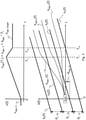
- Fig. 3 shows the execution of the method according to the invention using speed and distance profiles.
- a time based control parameter as part of a control profile comprising a target speed profile of the vehicle EGO as shown in Fig. 1 or Fig. 2 . If this control profile, in particular this control parameter, is supplied to the speed control system of the vehicle EGO as a target value, the vehicle EGO will adjust its speed according to the control profile, which causes acceleration or deceleration of the vehicle EGO.
- the target speed profile begins with an initial speed v ego,0 the vehicle is moving at time 0.
- the target speed profile is comprising an end point T m wherein the target speed v ego, target is reached.
- a switching point T 1 is shown between time 0 and the end point T m .
- the switching point T 1 divides the target speed profile into to control profile parts.
- the first control profile part extends from time 0 to the switching point T 1 wherein the second profile part extends from the switching point T 1 to the end point T m .
- the second control profile part causes the vehicle EGO exclusively to decrease its speed to reach v ego, target at the end point T m .
- the amount of the average acceleration from time 0 to T 1 and the amount of the average acceleration from time T 1 to T m are equal. In general, they can differ from each other. Further, the speed profile shown in the drawing comprises two control profile parts with a linear character. In general, profiles that are more complex are possible as well.
- this situation for example it is the object bringing the vehicle EGO into a position allowing the start of a lane change into a gap between two of the vehicles 1, 2, 3, 4.
- This situation is similar to the situation shown in Fig. 1 .
- the vehicle EGO shall move into the gap between vehicle 3 and 4, it has to adjust its position with reference to the other vehicles 1, 2, 3, 4 according to s ego, 1 (t) corresponding to the control profile shown in the drawing above. Therefore, the vehicle EGO has to accelerate to overtake vehicle 3 and to establish a safety distance to this vehicle 3.
- the acceleration stops by reaching the switching point T 1 wherein the vehicle EGO starts to reduce its speed to reach the target position between the vehicles 3 and 4 with the target speed v ego, target .
- the time points T 1 and T m and the amount of the acceleration and deceleration are determined by the determining of the profile shown above.
- another control profile is determined by the method according to the invention, causing the vehicle EGO to follow the trajectories according to the distances s ego, 2 (t) or s ego, 3 (t).
- the control profiles causing these trajectories differ from the control profile causing the trajectory according to s ego, 1 (t).
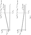
- Fig. 4 shows special use cases of the invention.
- the control profile comprises only one control profile part.
- Such control profiles are for example determined when the switching point T 1 is set equal to the end point T m .
- the upper drawing shows the case when the initial speed v ego, 0 shall be adjusted to a target speed v ego, target , wherein the initial speed v ego, 0 is smaller than the target speed v ego, target .
- the lower drawing shows the other case, wherein the initial speed v ego, 0 is higher than the target speed v ego, target .
- both cases only one control profile part can be identified wherein the corresponding control parameter only increases or decreases with an average acceleration or deceleration a ego .
- the acceleration or deceleration a ego is constant during the only control profile part.
- N indicates the number of gaps the vehicle EGO has to pass to reach the gap it will enter.
- T v a ego v L ⁇ v ego , 0 a ego describing the time which it takes to reach v L from v ego, 0 when using the acceleration a ego
- T d 2 a ego 2 d L 2 ⁇ d ego , 0 + N ⁇ d L a ego describing the time which it takes to change the distance offset from do to d L /2 with the acceleration a ego
- T m a ego T v a ego 1 ⁇ 2 1 ⁇ T d a ego T v a ego 2
- T 1 a ego T v a ego 1 ⁇ 1 2 1 ⁇ T d a ego T v a ego 2
Landscapes
- Engineering & Computer Science (AREA)
- Automation & Control Theory (AREA)
- Transportation (AREA)
- Mechanical Engineering (AREA)
- Physics & Mathematics (AREA)
- General Physics & Mathematics (AREA)
- Control Of Driving Devices And Active Controlling Of Vehicle (AREA)
- Traffic Control Systems (AREA)
- Control Of Velocity Or Acceleration (AREA)
Abstract
Description
- The present invention relates to a first method for adjusting the speed of a vehicle. Further, the invention relates to a method for adjusting the position of the vehicle by executing the first method. Finally, the invention relates to a device, a system, a vehicle, a computer programme product and a storage medium.
- In the following, autonomous vehicles are understood to be those that are configured in particular to execute the methods that are the subject-matters of the invention. In particular an autonomous vehicle is also a vehicle, that is configured only to execute the method according to the invention. Further, autonomous vehicles can be understood to be configured to drive partially or fully autonomous.
- Autonomous driving is a huge field for automotive development. Vehicles must interact with other traffic participants such as other autonomous or non-autonomous vehicles and take other constraints such as obstacles, pedestrians, speed limits, etc. into account. One part of this field relates to the adjusting of the speed of an autonomous vehicle. To reach a target speed from an initial speed several speed profiles are possible. Further, if the vehicle tries to reach a target position relative to another traffic participant it has to adjust its speed to reach this target position. For example, this target position is a position within or at the end of a platoon of several vehicles. However, the target position can be a starting position for a lane change as well. Therefore, there is a need for adjusting the speed of a vehicle and in particular for leading a vehicle into a target position.
- Therefore, it is the object of the present invention to show a solution for this problem.
- This object is reached by the subject-matters of the independent claims. Advantageous embodiments are subject-matters of the dependent claims.
- Preferably, a method is provided for adjusting the speed of a vehicle that is moving with an initial speed, to a target speed, comprising the steps:
- determining a control profile comprising at least one control profile part, wherein the control profile is comprising at least one control parameter for the vehicle and allowing the vehicle to change its speed from the initial speed to the target speed;
- adjusting the speed of the vehicle according to the control profile or supplying the control profile to a speed control system of the vehicle in order to adjust the speed of the vehicle.
- Preferably, the vehicle is comprising a speed control system that is configured to receive at least one control parameter, in particular a target value, and to adjust the speed of the vehicle in reaction to the control parameter.
- Preferably, the control parameter of the control profile is comprising a target value for the vehicle, wherein the vehicle is configured to reach the target value. Preferably, the target value is comprising a target acceleration value or a target acceleration profile, and/or a target speed value or a target speed profile, and/or a target force or target torque value or a target force or target torque profile, and/or a target engine load value or a target engine load profile, and/or a target brake demand value or a target brake demand profile. If at least one of these parameters is supplied to the speed control system of the vehicle, the vehicle will preferably react by its speed control system to reach the corresponding target value or profile.
- Preferably, one control profile part is comprising exclusively a control parameter causing an acceleration or a deceleration of the vehicle, wherein preferably, when the control profile consists of two control profile parts, one of the two control profile parts is comprising exclusively control parameter causing an acceleration and the other of the two control profile parts causing a deceleration. For example, if the control profile is comprising a target acceleration, one control profile part can exclusively comprise positive or negative target acceleration values. If the control profile is comprising a target speed, the control profile part causing an acceleration of the vehicle can comprise ascending speed values, wherein the control profile part causing a deceleration of the vehicle can comprise descending speed values.
- Preferably, the control profile is comprising a switching point separating two control profile parts of the control profile from each other. Preferably, the switching point is dividing the control profile into two control profile parts. The two control profile parts can comprise the same length, but in general do not need to have the same length.
- Preferably, the control profile is comprising an end point defining the end of the control profile and when the end point is reached the speed of the vehicle is preferably equal to the target speed.
- The switching point and/or the end point are preferably determined during the determining of the control profile.
- Preferably, the amount of the average acceleration and/or deceleration caused by two different control profile parts is equal. In particular, each control profile part can cause a constant acceleration and/or deceleration. Preferably, one of the two control profile parts can cause an acceleration and the other one a deceleration of the vehicle. These two control profile parts can be adjacent within the control profile.
- Preferably, at least one of the control profile parts is causing a linear adjusting of the speed, wherein preferably, the control profile is causing exclusively a linear adjusting of the speed. That means that the adjusting of the speed is executed under constant acceleration and/or deceleration. For example, if the control profile is comprising a target acceleration profile, the corresponding control profile part can comprise a constant acceleration value. If the control profile is comprising a target speed profile, the corresponding control profile part can comprise a linear speed profile.
- Preferably, the control profile is based on time and/or speed of the vehicle and/or distance of the vehicle. If the control profile is based on time, the switching point and/or the end point can be defined as special points of time within the control profile. If the control profile is based on speed, the switching point and/or the end point can be defined by a special speed value. In this case the end point can be a speed with respect to another vehicle, in particular the speed of the other vehicle. If the control profile is based on distance, the switching point and/or the end point can be defined as special points along the driveway of the vehicle. In this case the end point can be a position with respect to another vehicle.
- Preferably, a method for leading a vehicle that is moving on a lane into a target position with respect to at least one other vehicle is provided, comprising the steps:
- determining a current position of the vehicle with respect to the at least one other vehicle;
- determining the target position with respect to the at least one other vehicle;
- executing the method as described above to reach the target position.
- The end point of the control profile can also be the target position.
- Preferably, the target position and/or the current position are longitudinal positions with respect to the direction of travel of the vehicle.
- This method can be used to adjust the position of the vehicle with respect to at least one other vehicle by adjusting the speed of the vehicle by the execution of the method as described above, wherein the control profile is determined and applied to the vehicle. However, the method for adjusting the speed as described above is only executed if the current position of the vehicle is not equal to the target position.
- Preferably, the control profile is determined in such way that the speed of the vehicle is equal to the target speed when reaching the target position. Advantageously, if the method is used to close a gap between the vehicle and another vehicle that is the last vehicle of a platoon, the vehicle reaches the target position, which is a position behind the other vehicle, with the same speed as the other vehicle. Therefore, the vehicle can be integrated into the platoon by reaching the target position. In another use case the method is used to lead the vehicle in a position with respect to another vehicle moving on an adjacent line. This position can be a starting position for a lane change, which can be defined by a safety distance with respect to the other vehicle, wherein the vehicle has to reach this safety distance before starting the lane change manoeuvre. The starting position can be in front or behind the other vehicle. Further, more than just one vehicle can be taken into account to determine the starting position, for example the starting position is determined by a gap between two vehicles moving behind each other on a lane adjacent to the lane where the vehicle is moving.
- In general, at least one other vehicle or the at least one other vehicle is moving in front of the vehicle or behind the vehicle or on an adjacent lane.
- Preferably, one of the methods above is comprising a step wherein determining the target speed from an external source is executed. In particular, the external source is a traffic sign and/or a digital source and/or the speed of at least one other vehicle. As a digital source, a speed limit from digital map data can be used. If the speed of the vehicle shall be adjusted to the speed of another vehicle, the target speed can be determined from the speed of the other vehicle. Preferably, the target speed is determined by the use of a detection means, in particular a camera, a radar sensor, a GPS-receiver, a radio receiver.
- Preferably, the control profile, in particular at least one control profile part is determined under consideration of time optimal, wear optimal and/or energy optimal aspects.
- According to a special aspect, the invention models the preparation for a lane change, in which the vehicle intends to merge into an adjacent lane which has traffic moving with a certain speed and distance between the vehicles. The following initial parameters are taking into account: the speed of the vehicle, the speed of the vehicles in the adjacent target lane, the distance of vehicles in adjacent lane, and the longitudinal offset distance between the vehicle and the closest vehicle in the adjacent lane. In the preparation phase, the vehicle aims to reach the point at which it can perform a safe lane change into that target lane. For a safe lane change, the following conditions must be fulfilled: its speed must be the same as the vehicles in the target lane, and its longitudinal offset must be in between two vehicles or at least at a safe distance from the preceding and the following vehicle. The total time which this preparation for a lane change takes, is modelled into two control profile parts, each of which has the same constant acceleration, but with opposite sign. This two-split preparation allows that the vehicle can reach the conditions for a safe lane change from any combination of the initial conditions. This simple model allows to formulate a relation between the following variables: vehicle acceleration, the total lane change preparation time and the time instance where the sign of the acceleration swaps (the switching point separating the total control profile into two control profile parts). The total duration of the preparation phase depends on the initial conditions as well as on the selected acceleration. The mathematical relation between these variables and parameters allows judgement if the lane change preparation is completed within a given time, considering limited lane change length and limited vehicle acceleration capabilities. Also, the algorithm allows to select an acceleration which is optimal under certain conditions, e.g. regarding fuel efficiency, shortest possible time, or other criteria. The approach can also indicate which of the vehicle gaps in the moving traffic lane provides the best possible gap in between two vehicles moving on the target lane, where the vehicle can merge, again depending on its capabilities and boundary conditions. If there is no limit on the merging distance, then the preparation of the control profile with several control profile parts can default into a single time period with a constant acceleration, after which the vehicle is in the proper location for performing the lane change.
- Preferably, a device for executing a method as described above is provided, comprising:
- control means configured to cause the device the execution of the method as described above;
- an interface configured for supplying the control profile to the vehicle; and/or
- an interface for receiving data from the vehicle, in particular the speed of the vehicle and/or the position of the vehicle with reference to other vehicles.
- Preferably, the interface can supply the control profile directly to the speed control system of the vehicle. The control means is preferably comprising an electronic control unit, like an ECU. Therefore, by providing the device in the vehicle, the vehicle can be configured for executing the method according to the invention.
- Further preferably, a system is provided, comprising:
- a device as described above; and
- at least one detection means configured to detect information from the surrounding of the vehicle, wherein preferably, the at least one detection means is comprising a camera, a radar sensor, a GPS-receiver and/or a radio receiver, wherein preferably the system is configured to determine the target speed and/or the target position from the information from the detection means.
- Preferably a vehicle, in particular an autonomous vehicle, is provided comprising a device as described above or a system as described above. Alternatively, the vehicle is configured to execute the method as described above in another way.
- Preferably, a computer program product is provided, comprising code means configured to cause a device, in particular a device as described above, to execute the method as described above.
- Preferably, a storage medium is provided comprising a computer program product as described above.
- In particular, the invention allows to adjust the speed of the vehicle and in addition its position with respect to another vehicle. This can be used for a driver assistance system or a fully autonomously driving vehicle.
- In particular, the invention can determine a feasibility for a lane change from initial conditions like the speed of the vehicle, of at least one other vehicle and of their distances with respect to each other.
- In particular, the behaviour of other traffic participants can be taken into account.
- In particular, the invention can provide the time after which the adjusting of the speed is finished.
- In the following, general and specific aspects of the invention are explained in more detail using the attached drawings.
- In detail,
- Fig. 1
- shows a traffic situation for the executing of the method according to the invention,
- Fig. 2
- shows another traffic situation for the executing of the method according to the invention,
- Fig. 3
- shows the execution of the method according to the invention using speed and distance profiles, and
- Fig. 4
- shows special use cases of the invention.
-
Fig. 1 shows a traffic situation seen from above for the executing of the method according to the invention. - Two lanes L1, L2 are shown in the drawing, extending from the left to the right and being parallel and adjacent to each other. In the drawing traffic is moving on both lanes L1, L2 from the left to the right. A vehicle EGO moves on the lane L1 with a speed vego, 0 from the left to the right. The vehicle EGO is configured to adjust its speed by a speed control system according to a control parameter that can be supplied to the speed control system of the vehicle EGO. On lane L2, four
vehicles vehicles vehicle 2. Thevehicles - The lane L1 where the vehicle EGO is moving, is limited in its extension to the right. For example, lane L1 is a merging lane. Therefore, the vehicle EGO needs to change to lane L2 by a lane change manoeuvre. However, before the vehicle EGO can execute the lane change manoeuvre, it has to adjust its position and its speed with reference to the
vehicles - Above the lanes L1, L2, a time axis t and an axis indicating the distance s(t) are shown, wherein the axis indicating the distance s(t) corresponds to the distance the vehicle EGO moves from left to right.
- In this situation, it is an object to get the vehicle EGO into a position on lane L1 with respect to at least one of the
vehicles vehicles - According to the invention, a control profile is determined comprising at least one control parameter allowing adjusting the speed of the vehicle EGO to a target speed. The target speed can be determined as stated above, from the speed vL of the
vehicles - In the drawing, a switching point T1 is shown, which is determined as a part of the control profile. In this embodiment of the invention the switching point is a point of time, whereby two control profile parts are separated.
- Further, an end point Tm is shown, which is determined as a part of the control profile. In this embodiment of the invention the end point is a point of time, whereby the ending of the control profile and its duration is defined.
- During the time period from 0 to T1, adjusting the speed of the vehicle EGO is executed according to a first control profile part and during the time period from T1 to Tm, adjusting the speed of the vehicle EGO is executed according to a second control profile part. For example, both control profile parts can be configured to cause exclusively acceleration of the vehicle EGO during the executing one of both control profile parts, wherein during executing of the other control profile part exclusively deceleration of the vehicle EGO is caused.
- By the determination of the end point Tm the time is set for adjusting the distance d0, ego to the distance needed to join the platoon and for adjusting the speed of the vehicle EGO to a corresponding speed.
-
Fig. 2 shows another traffic situation seen from above for the executing of the method according to the invention. - A vehicle EGO is shown which corresponds to the vehicle EGO of
Fig. 1 . The vehicle EGO is moving with its speed vego, 0 from the left to the right on a lane L3 which is extending from the left to the right. - The vehicle EGO is approaching to
several vehicles vehicles vehicles Fig. 1 . In the situation shown on the drawing, the vehicle EGO is in an initial position d0, ego with reference to thevehicle 1. - Above the lane L3, a time axis t and an axis indicating the distance s(t) are shown, wherein the axis indicating the distance s(t) corresponds to the distance the vehicle EGO moves from left to right.
- In this situation, it can be an object to get the vehicle EGO into a position on lane L3 with respect to at least one of the
vehicles vehicle 1, wherein the vehicle EGO can join the platoon of thevehicles vehicle 1 indeed. Therefore, the speed of the vehicle EGO in the target position behindvehicle 1 must not be too slow or too fast. For example, the speed of the vehicle EGO should be equal to the speed vL of thevehicles - According to the invention, a control profile is determined comprising at least one control parameter allowing adjusting the speed of the vehicle EGO to a target speed. The target speed can be determined as stated above, from the speed vL of the
vehicles - In the drawing, a switching point T1 is shown, which is determined as a part of the control profile. In this embodiment of the invention the switching point T1 is a point of time, whereby two control profile parts are separated.
- Further, an end point Tm is shown, which is determined as a part of the control profile. In this embodiment of the invention the end point Tm is a point of time, whereby the ending of the control profile and its duration is defined.
- During the time period from 0 to T1, adjusting the speed of the vehicle EGO is executed according to a first control profile part and during the time period from T1 to Tm, adjusting the speed of the vehicle EGO is executed according to a second control profile part. For example, both control profile parts can be configured to cause exclusively acceleration of the vehicle EGO during the executing one of both control profile parts, wherein during executing of the other control profile part exclusively deceleration of the vehicle EGO is caused.
- By the determination of the end point Tm the time is set for adjusting the distance d0, ego to the distance needed to join the platoon and for adjusting the speed of the vehicle EGO to a corresponding speed.
-
Fig. 3 shows the execution of the method according to the invention using speed and distance profiles. - In the drawing shown above, a time based control parameter as part of a control profile is shown comprising a target speed profile of the vehicle EGO as shown in
Fig. 1 orFig. 2 . If this control profile, in particular this control parameter, is supplied to the speed control system of the vehicle EGO as a target value, the vehicle EGO will adjust its speed according to the control profile, which causes acceleration or deceleration of the vehicle EGO. - The target speed profile begins with an initial speed vego,0 the vehicle is moving at
time 0. The target speed profile is comprising an end point Tm wherein the target speed vego, target is reached. Betweentime 0 and the end point Tm, a switching point T1 is shown. The switching point T1 divides the target speed profile into to control profile parts. The first control profile part extends fromtime 0 to the switching point T1 wherein the second profile part extends from the switching point T1 to the end point Tm. - The first control profile part causes the vehicle EGO exclusively to increase its speed wherein at the switching point T1 the speed can be calculated as

time 0 to the switching point T1. It has to be noted, that the value of vego(T1) is bigger than the target speed vego, target. This is the general case when the control profile consists of two parts and when the control profile starts with a control profile part causing the acceleration of the vehicle EGO. - The second control profile part causes the vehicle EGO exclusively to decrease its speed to reach vego, target at the end point Tm.
- In the case shown in the drawing, the amount of the average acceleration from
time 0 to T1 and the amount of the average acceleration from time T1 to Tm are equal. In general, they can differ from each other. Further, the speed profile shown in the drawing comprises two control profile parts with a linear character. In general, profiles that are more complex are possible as well. - In the lower part of
Fig. 3 time based plots of the distance s(t) the vehicle EGO andother vehicles vehicles vehicles - Further, in the drawing three trajectories sego, 1(t), sego, 2(t), sego, 3(t) are shown by dotted lines representing three possible ways the vehicle EGO can take to adjust its speed and its position with reference to the
vehicles time 0 the vehicle EGO is moving between thevehicles vehicle 2. - In this situation, for example it is the object bringing the vehicle EGO into a position allowing the start of a lane change into a gap between two of the
vehicles Fig. 1 . - If the vehicle EGO shall move into the gap between
vehicle other vehicles vehicle 3 and to establish a safety distance to thisvehicle 3. The acceleration stops by reaching the switching point T1 wherein the vehicle EGO starts to reduce its speed to reach the target position between thevehicles - If the vehicle EGO shall change into another gap for example between the
vehicles -
Fig. 4 shows special use cases of the invention. In these cases the control profile comprises only one control profile part. Such control profiles are for example determined when the switching point T1 is set equal to the end point Tm. - The upper drawing shows the case when the initial speed vego, 0 shall be adjusted to a target speed vego, target, wherein the initial speed vego, 0 is smaller than the target speed vego, target. The lower drawing shows the other case, wherein the initial speed vego, 0 is higher than the target speed vego, target. In both cases only one control profile part can be identified wherein the corresponding control parameter only increases or decreases with an average acceleration or deceleration aego. In the case shown in the drawing, the acceleration or deceleration aego is constant during the only control profile part. In these special cases the speed at the switching point T1 or end point Tm can be calculated as follows:

- In the following, a particular embodiment of the invention is described based on mathematical formulas. This is a general and simplified use case of the invention for determination of a time based control profile comprising two control profile parts, wherein no constraint are considered. The embodiment shows the determination of a control profile, in particular the determination of the switching point T1 and the end point Tm for the situation shown in
Fig. 1 . For simplification, it is assumed that thevehicles - Therefore, the distance sL(t) driven by one of the
vehicles 
- The speed vego(Tm) of the vehicle EGO at the end point Tm can be calculated as follows:

- Further, the distance sego(Tm) driven by the vehicle EGO at the end point Tm can be calculated as follows:

- For the preparation of a lane change, the vehicle EGO shall have the same speed as the
vehicles 

- Wherein N indicates the number of gaps the vehicle EGO has to pass to reach the gap it will enter.
- Since the amount of the acceleration and deceleration aego of the vehicle EGO is assumed to be equal, at the switching point T1, the following equation can be formulated:

- With

- From the equations above, the following expressions for T1 can be formed:


- With the following expressions


- This is the general relation between the control parameters T1, Tm and aego based on the initial parameters vego, 0, vL, dego, 0, dL. That means, that only from these initial parameters, a control profile can be determined.
-
- 1
- vehicle
- 2
- vehicle
- 3
- vehicle
- 4
- vehicle
- aego
- acceleration/deceleration of the vehicle EGO
- dL
- distance between vehicles
- dL, i
- distance between vehicles
- EGO
- vehicle
- Li
- lane
- si
- distance
- S10
- method step
- S12
- method step
- S13
- method step
- S14
- method step
- S16
- method step
- T1
- switching point
- Tm
- end point
- vego
- speed of the vehicle EGO
- vego, 0
- initial speed of the vehicle EGO
- vego, target
- target speed of the vehicle EGO
- vL
- speed of the
vehicles
Claims (15)
- Method for adjusting the speed (vego) of a vehicle (EGO) moving with an initial speed (vego, 0) to a target speed (vego, target), comprising the steps:- step (S14): determining a control profile comprising at least one control profile part, wherein the control profile is comprising at least one control parameter for the vehicle (EGO) and allowing the vehicle (EGO) to change its speed (vego) from the initial speed (vego, 0) to the target speed (vego, target);- step (S16): adjusting the speed (vego) of the vehicle (EGO) according to the control profile or supplying the control profile to a speed control system of the vehicle in order to adjust the speed (vego) of the vehicle (EGO).
- Method according to claim 1, wherein
one control profile part is comprising exclusively control parameter causing an acceleration or a deceleration, wherein preferably, when the control profile consists of two control profile parts, one of the two control profile parts is comprising exclusively control parameter causing an acceleration and the other of the two control profile parts causing a deceleration. - Method according to claim 1 or 2, wherein
the control profile is comprising a switching point (T1) separating two control profile parts of the control profile from each other, preferably the switching point (T1) is dividing the control profile into two control profile parts, and/or wherein
the control profile is comprising an end point (Tm) defining the end of the control profile when reached the speed of the vehicle (EGO) is equal to the target speed (vego, target). - Method according to one of the preceding claims, wherein
the amount of the average acceleration and/or deceleration (aego) caused by two different control profile parts is equal. - Method according to one of the preceding claims, wherein
at least one of the control profile parts is causing a linear adjusting (S16) of the speed (vego), wherein preferably, the control profile is causing exclusively a linear adjusting (S16) of the speed (vego). - Method according to one of the preceding claims, wherein
the control profile is based on time and/or speed (vego) of the vehicle (EGO) and/or distance (sego) of the vehicle (EGO). - Method according to one of the preceding claims, wherein
the control parameter is comprising a target value, preferably a target acceleration value or a target acceleration profile, and/or a target speed value or a target speed profile, and/or a target force or target torque value or a target force or target torque profile, and/or a target engine load value or a target engine load profile, and/or a target brake demand value or a target brake demand profile. - Method for leading a vehicle (EGO) that is moving on a lane into a target position (dego, target) with respect to at least one other vehicle (1, 2, 3, 4), comprising the steps:- step (S10): determining a current position (dego, 0) of the vehicle (EGO) with respect to the at least one other vehicle (1, 2, 3, 4);- step (S12): determining the target position (dego, target) with respect to the at least one other vehicle (1, 2, 3, 4);if the current position (dego, 0) is not equal to the target position (dego, target):- executing the method according to one of the claims 1 to 7 to reach the target position (dego, target).
- Method according to claim 8, wherein
the control profile is determined in such way that the speed (vego) of the vehicle (EGO) is comprising the target speed (vego, target) when reaching the target position (dego, target), and/or wherein
the at least one other vehicle (1, 2, 3, 4) is moving in front of the vehicle (EGO) or behind the vehicle (EGO) or on an adjacent lane. - Method according to one of the claims 1 to 9, comprising the step:- step (S13): determining the target speed (vego, target) from an external source, in particular from a traffic sign and/or from a digital source and/or from the speed (vL) of at least one other vehicle (1, 2, 3, 4).
- Device for executing a method according to one of the claims 1 to 10, comprising:- control means configured to cause the executing of the method according to one of the claims 1 to 10 by the device;- an interface configured to supply the control profile to the vehicle (EGO); and/or- an interface for receiving data from the vehicle.
- System comprising:- a device according to claim 11; and- at least one detection means configured to detect information from the surrounding of the vehicle (EGO), wherein preferably, the at least one detection means is comprising a camera, a radar sensor, a GPS-receiver and/or a radio receiver, wherein preferably
the system is configured to determine the target speed (vego, target) and/or the target position (dego, target) from the information of the detection means. - Vehicle (EGO) comprising a device according to claim 11 or a system according to claim 12 or wherein the vehicle (EGO) is configured to execute the method according to one of the claims 1 to 10.
- Computer program product comprising code means configured to cause a device, in particular a device according to claim 11, to execute the method according to one of the claims 1 to 10.
- Storage medium comprising a computer program product according to claim 14.
Priority Applications (4)
| Application Number | Priority Date | Filing Date | Title |
|---|---|---|---|
| EP20196131.5A EP3967564B1 (en) | 2020-09-15 | 2020-09-15 | Method for adjusting the speed of a vehicle |
| PCT/EP2021/073614 WO2022058133A1 (en) | 2020-09-15 | 2021-08-26 | Method for adjusting the speed of a vehicle |
| CN202180063263.5A CN116234738A (en) | 2020-09-15 | 2021-08-26 | Method for adjusting the speed of a vehicle |
| US18/041,882 US12559100B2 (en) | 2020-09-15 | 2021-08-26 | Method for adjusting the speed of a vehicle |
Applications Claiming Priority (1)
| Application Number | Priority Date | Filing Date | Title |
|---|---|---|---|
| EP20196131.5A EP3967564B1 (en) | 2020-09-15 | 2020-09-15 | Method for adjusting the speed of a vehicle |
Publications (2)
| Publication Number | Publication Date |
|---|---|
| EP3967564A1 true EP3967564A1 (en) | 2022-03-16 |
| EP3967564B1 EP3967564B1 (en) | 2024-05-22 |
Family
ID=72521377
Family Applications (1)
| Application Number | Title | Priority Date | Filing Date |
|---|---|---|---|
| EP20196131.5A Active EP3967564B1 (en) | 2020-09-15 | 2020-09-15 | Method for adjusting the speed of a vehicle |
Country Status (4)
| Country | Link |
|---|---|
| US (1) | US12559100B2 (en) |
| EP (1) | EP3967564B1 (en) |
| CN (1) | CN116234738A (en) |
| WO (1) | WO2022058133A1 (en) |
Families Citing this family (1)
| Publication number | Priority date | Publication date | Assignee | Title |
|---|---|---|---|---|
| JP7509103B2 (en) * | 2021-08-31 | 2024-07-02 | トヨタ自動車株式会社 | Vehicle driving control device and method, and computer program |
Citations (4)
| Publication number | Priority date | Publication date | Assignee | Title |
|---|---|---|---|---|
| DE202012101687U1 (en) * | 2012-05-08 | 2012-05-29 | Deutsches Zentrum für Luft- und Raumfahrt e.V. | Lane change assistance system |
| US20150046058A1 (en) * | 2012-03-15 | 2015-02-12 | Toyota Jidosha Kabushiki Kaisha | Driving assist device |
| US20180050675A1 (en) * | 2016-08-17 | 2018-02-22 | Ford Global Technologies, Llc | Apparatus for reducing a speed of a motor vehicle |
| US20180237011A1 (en) * | 2017-02-23 | 2018-08-23 | Magna Electronics Inc. | Vehicular adaptive cruise control with enhanced vehicle control |
Family Cites Families (9)
| Publication number | Priority date | Publication date | Assignee | Title |
|---|---|---|---|---|
| MY191084A (en) * | 2015-07-28 | 2022-05-30 | Nissan Motor | Method for controlling travel control device, and travel control device |
| US10703367B2 (en) * | 2017-05-31 | 2020-07-07 | Nio Usa, Inc. | Utilization of smoothing functions for acceleration and deceleration profile generation |
| JP6933080B2 (en) * | 2017-10-05 | 2021-09-08 | いすゞ自動車株式会社 | Vehicle speed control device |
| US11453393B2 (en) * | 2017-10-09 | 2022-09-27 | Magna Electronics Inc. | Autonomous vehicle with path planning system |
| JP7260964B2 (en) * | 2018-06-04 | 2023-04-19 | 日立Astemo株式会社 | VEHICLE CONTROL DEVICE AND CONTROL METHOD |
| WO2019241565A1 (en) * | 2018-06-13 | 2019-12-19 | Skip Transport, Inc. | System and method for vehicle operation control |
| CN113544023B (en) * | 2019-03-01 | 2022-08-30 | 日产自动车株式会社 | Vehicle travel control method and travel control device |
| KR20210130324A (en) * | 2020-04-21 | 2021-11-01 | 현대자동차주식회사 | Advanced Driver Assistance System, Vehicle having the same and method for controlling the vehicle |
| JP7429172B2 (en) * | 2020-09-03 | 2024-02-07 | 本田技研工業株式会社 | Vehicle control device, vehicle control method, and program |
-
2020
- 2020-09-15 EP EP20196131.5A patent/EP3967564B1/en active Active
-
2021
- 2021-08-26 US US18/041,882 patent/US12559100B2/en active Active
- 2021-08-26 CN CN202180063263.5A patent/CN116234738A/en active Pending
- 2021-08-26 WO PCT/EP2021/073614 patent/WO2022058133A1/en not_active Ceased
Patent Citations (4)
| Publication number | Priority date | Publication date | Assignee | Title |
|---|---|---|---|---|
| US20150046058A1 (en) * | 2012-03-15 | 2015-02-12 | Toyota Jidosha Kabushiki Kaisha | Driving assist device |
| DE202012101687U1 (en) * | 2012-05-08 | 2012-05-29 | Deutsches Zentrum für Luft- und Raumfahrt e.V. | Lane change assistance system |
| US20180050675A1 (en) * | 2016-08-17 | 2018-02-22 | Ford Global Technologies, Llc | Apparatus for reducing a speed of a motor vehicle |
| US20180237011A1 (en) * | 2017-02-23 | 2018-08-23 | Magna Electronics Inc. | Vehicular adaptive cruise control with enhanced vehicle control |
Also Published As
| Publication number | Publication date |
|---|---|
| EP3967564B1 (en) | 2024-05-22 |
| US12559100B2 (en) | 2026-02-24 |
| CN116234738A (en) | 2023-06-06 |
| US20230311871A1 (en) | 2023-10-05 |
| WO2022058133A1 (en) | 2022-03-24 |
Similar Documents
| Publication | Publication Date | Title |
|---|---|---|
| US6873911B2 (en) | Method and system for vehicle operator assistance improvement | |
| EP3683782B1 (en) | Method for assisting a driver, driver assistance system, and vehicle including such driver assistance system | |
| US12017648B2 (en) | Vehicle control device | |
| EP3115272B1 (en) | Control system of automated driving vehicle | |
| EP3208786B1 (en) | Method and system for evaluating inter-vehicle traffic gaps and time instances to perform a lane change manoeuvre | |
| US11009872B2 (en) | Vehicle controller | |
| US10875529B2 (en) | Vehicle control device | |
| JP3714258B2 (en) | Recommended operation amount generator for vehicles | |
| CN110001638B (en) | Travel control device for autonomous vehicle | |
| US10583839B2 (en) | Method of lane change decision-making and path planning | |
| US11091035B2 (en) | Automatic driving system | |
| CN111746542B (en) | Method and system for vehicle intelligent lane change reminding, vehicle and storage medium | |
| EP2332795B1 (en) | Driving support system, method, program, and computer readable medium | |
| CN106428007A (en) | Autonomous driving control apparatus and method for vehicle | |
| CN111332283A (en) | Method and system for controlling a motor vehicle | |
| JP2019121063A (en) | Traveling control device for automatic driving vehicle | |
| JP2019107996A (en) | Running control device for automatic driving vehicle | |
| EP3145777A1 (en) | Method and system for improving the operating efficiency of a vehicle during driving of a vehicle along a route of travel | |
| EP3660459A1 (en) | Route candidate setting system, vehicle, route candidate setting method, and computer program product | |
| EP4173915A1 (en) | Systems and methods for handling cut-in traffic for autonomous driving | |
| US12559100B2 (en) | Method for adjusting the speed of a vehicle | |
| EP4481707B1 (en) | Construction zone determining method and construction zone determining device | |
| US20260109352A1 (en) | Methods, Data Processing Device and Software for Determining a Deceleration Strategy for a Vehicle | |
| Kim et al. | Serviceable Energy-Optimal Regenerative Braking Control for Age of MECA: A Practical Design and Implementation | |
| JP2026064310A (en) | Vehicle control system |
Legal Events
| Date | Code | Title | Description |
|---|---|---|---|
| PUAI | Public reference made under article 153(3) epc to a published international application that has entered the european phase |
Free format text: ORIGINAL CODE: 0009012 |
|
| STAA | Information on the status of an ep patent application or granted ep patent |
Free format text: STATUS: THE APPLICATION HAS BEEN PUBLISHED |
|
| AK | Designated contracting states |
Kind code of ref document: A1 Designated state(s): AL AT BE BG CH CY CZ DE DK EE ES FI FR GB GR HR HU IE IS IT LI LT LU LV MC MK MT NL NO PL PT RO RS SE SI SK SM TR |
|
| STAA | Information on the status of an ep patent application or granted ep patent |
Free format text: STATUS: REQUEST FOR EXAMINATION WAS MADE |
|
| 17P | Request for examination filed |
Effective date: 20220916 |
|
| RBV | Designated contracting states (corrected) |
Designated state(s): AL AT BE BG CH CY CZ DE DK EE ES FI FR GB GR HR HU IE IS IT LI LT LU LV MC MK MT NL NO PL PT RO RS SE SI SK SM TR |
|
| RAP3 | Party data changed (applicant data changed or rights of an application transferred) |
Owner name: KNORR-BREMSE SYSTEME FUER NUTZFAHRZEUGE GMBH |
|
| GRAP | Despatch of communication of intention to grant a patent |
Free format text: ORIGINAL CODE: EPIDOSNIGR1 |
|
| STAA | Information on the status of an ep patent application or granted ep patent |
Free format text: STATUS: GRANT OF PATENT IS INTENDED |
|
| INTG | Intention to grant announced |
Effective date: 20240117 |
|
| GRAS | Grant fee paid |
Free format text: ORIGINAL CODE: EPIDOSNIGR3 |
|
| GRAA | (expected) grant |
Free format text: ORIGINAL CODE: 0009210 |
|
| STAA | Information on the status of an ep patent application or granted ep patent |
Free format text: STATUS: THE PATENT HAS BEEN GRANTED |
|
| P01 | Opt-out of the competence of the unified patent court (upc) registered |
Effective date: 20240327 |
|
| P02 | Opt-out of the competence of the unified patent court (upc) changed |
Effective date: 20240327 |
|
| AK | Designated contracting states |
Kind code of ref document: B1 Designated state(s): AL AT BE BG CH CY CZ DE DK EE ES FI FR GB GR HR HU IE IS IT LI LT LU LV MC MK MT NL NO PL PT RO RS SE SI SK SM TR |
|
| REG | Reference to a national code |
Ref country code: GB Ref legal event code: FG4D |
|
| REG | Reference to a national code |
Ref country code: CH Ref legal event code: EP |
|
| REG | Reference to a national code |
Ref country code: DE Ref legal event code: R096 Ref document number: 602020031210 Country of ref document: DE |
|
| REG | Reference to a national code |
Ref country code: IE Ref legal event code: FG4D |
|
| REG | Reference to a national code |
Ref country code: LT Ref legal event code: MG9D |
|
| REG | Reference to a national code |
Ref country code: NL Ref legal event code: MP Effective date: 20240522 |
|
| PG25 | Lapsed in a contracting state [announced via postgrant information from national office to epo] |
Ref country code: IS Free format text: LAPSE BECAUSE OF FAILURE TO SUBMIT A TRANSLATION OF THE DESCRIPTION OR TO PAY THE FEE WITHIN THE PRESCRIBED TIME-LIMIT Effective date: 20240922 |
|
| PG25 | Lapsed in a contracting state [announced via postgrant information from national office to epo] |
Ref country code: BG Free format text: LAPSE BECAUSE OF FAILURE TO SUBMIT A TRANSLATION OF THE DESCRIPTION OR TO PAY THE FEE WITHIN THE PRESCRIBED TIME-LIMIT Effective date: 20240522 |
|
| PG25 | Lapsed in a contracting state [announced via postgrant information from national office to epo] |
Ref country code: FI Free format text: LAPSE BECAUSE OF FAILURE TO SUBMIT A TRANSLATION OF THE DESCRIPTION OR TO PAY THE FEE WITHIN THE PRESCRIBED TIME-LIMIT Effective date: 20240522 Ref country code: HR Free format text: LAPSE BECAUSE OF FAILURE TO SUBMIT A TRANSLATION OF THE DESCRIPTION OR TO PAY THE FEE WITHIN THE PRESCRIBED TIME-LIMIT Effective date: 20240522 |
|
| PG25 | Lapsed in a contracting state [announced via postgrant information from national office to epo] |
Ref country code: GR Free format text: LAPSE BECAUSE OF FAILURE TO SUBMIT A TRANSLATION OF THE DESCRIPTION OR TO PAY THE FEE WITHIN THE PRESCRIBED TIME-LIMIT Effective date: 20240823 |
|
| PG25 | Lapsed in a contracting state [announced via postgrant information from national office to epo] |
Ref country code: PT Free format text: LAPSE BECAUSE OF FAILURE TO SUBMIT A TRANSLATION OF THE DESCRIPTION OR TO PAY THE FEE WITHIN THE PRESCRIBED TIME-LIMIT Effective date: 20240923 |
|
| REG | Reference to a national code |
Ref country code: AT Ref legal event code: MK05 Ref document number: 1688540 Country of ref document: AT Kind code of ref document: T Effective date: 20240522 |
|
| PG25 | Lapsed in a contracting state [announced via postgrant information from national office to epo] |
Ref country code: NL Free format text: LAPSE BECAUSE OF FAILURE TO SUBMIT A TRANSLATION OF THE DESCRIPTION OR TO PAY THE FEE WITHIN THE PRESCRIBED TIME-LIMIT Effective date: 20240522 |
|
| PG25 | Lapsed in a contracting state [announced via postgrant information from national office to epo] |
Ref country code: ES Free format text: LAPSE BECAUSE OF FAILURE TO SUBMIT A TRANSLATION OF THE DESCRIPTION OR TO PAY THE FEE WITHIN THE PRESCRIBED TIME-LIMIT Effective date: 20240522 |
|
| PG25 | Lapsed in a contracting state [announced via postgrant information from national office to epo] |
Ref country code: AT Free format text: LAPSE BECAUSE OF FAILURE TO SUBMIT A TRANSLATION OF THE DESCRIPTION OR TO PAY THE FEE WITHIN THE PRESCRIBED TIME-LIMIT Effective date: 20240522 |
|
| PG25 | Lapsed in a contracting state [announced via postgrant information from national office to epo] |
Ref country code: PL Free format text: LAPSE BECAUSE OF FAILURE TO SUBMIT A TRANSLATION OF THE DESCRIPTION OR TO PAY THE FEE WITHIN THE PRESCRIBED TIME-LIMIT Effective date: 20240522 |
|
| PG25 | Lapsed in a contracting state [announced via postgrant information from national office to epo] |
Ref country code: LV Free format text: LAPSE BECAUSE OF FAILURE TO SUBMIT A TRANSLATION OF THE DESCRIPTION OR TO PAY THE FEE WITHIN THE PRESCRIBED TIME-LIMIT Effective date: 20240522 |
|
| PG25 | Lapsed in a contracting state [announced via postgrant information from national office to epo] |
Ref country code: PT Free format text: LAPSE BECAUSE OF FAILURE TO SUBMIT A TRANSLATION OF THE DESCRIPTION OR TO PAY THE FEE WITHIN THE PRESCRIBED TIME-LIMIT Effective date: 20240923 Ref country code: PL Free format text: LAPSE BECAUSE OF FAILURE TO SUBMIT A TRANSLATION OF THE DESCRIPTION OR TO PAY THE FEE WITHIN THE PRESCRIBED TIME-LIMIT Effective date: 20240522 Ref country code: NO Free format text: LAPSE BECAUSE OF FAILURE TO SUBMIT A TRANSLATION OF THE DESCRIPTION OR TO PAY THE FEE WITHIN THE PRESCRIBED TIME-LIMIT Effective date: 20240822 Ref country code: NL Free format text: LAPSE BECAUSE OF FAILURE TO SUBMIT A TRANSLATION OF THE DESCRIPTION OR TO PAY THE FEE WITHIN THE PRESCRIBED TIME-LIMIT Effective date: 20240522 Ref country code: LV Free format text: LAPSE BECAUSE OF FAILURE TO SUBMIT A TRANSLATION OF THE DESCRIPTION OR TO PAY THE FEE WITHIN THE PRESCRIBED TIME-LIMIT Effective date: 20240522 Ref country code: IS Free format text: LAPSE BECAUSE OF FAILURE TO SUBMIT A TRANSLATION OF THE DESCRIPTION OR TO PAY THE FEE WITHIN THE PRESCRIBED TIME-LIMIT Effective date: 20240922 Ref country code: HR Free format text: LAPSE BECAUSE OF FAILURE TO SUBMIT A TRANSLATION OF THE DESCRIPTION OR TO PAY THE FEE WITHIN THE PRESCRIBED TIME-LIMIT Effective date: 20240522 Ref country code: GR Free format text: LAPSE BECAUSE OF FAILURE TO SUBMIT A TRANSLATION OF THE DESCRIPTION OR TO PAY THE FEE WITHIN THE PRESCRIBED TIME-LIMIT Effective date: 20240823 Ref country code: FI Free format text: LAPSE BECAUSE OF FAILURE TO SUBMIT A TRANSLATION OF THE DESCRIPTION OR TO PAY THE FEE WITHIN THE PRESCRIBED TIME-LIMIT Effective date: 20240522 Ref country code: ES Free format text: LAPSE BECAUSE OF FAILURE TO SUBMIT A TRANSLATION OF THE DESCRIPTION OR TO PAY THE FEE WITHIN THE PRESCRIBED TIME-LIMIT Effective date: 20240522 Ref country code: BG Free format text: LAPSE BECAUSE OF FAILURE TO SUBMIT A TRANSLATION OF THE DESCRIPTION OR TO PAY THE FEE WITHIN THE PRESCRIBED TIME-LIMIT Effective date: 20240522 Ref country code: AT Free format text: LAPSE BECAUSE OF FAILURE TO SUBMIT A TRANSLATION OF THE DESCRIPTION OR TO PAY THE FEE WITHIN THE PRESCRIBED TIME-LIMIT Effective date: 20240522 Ref country code: RS Free format text: LAPSE BECAUSE OF FAILURE TO SUBMIT A TRANSLATION OF THE DESCRIPTION OR TO PAY THE FEE WITHIN THE PRESCRIBED TIME-LIMIT Effective date: 20240822 |
|
| PG25 | Lapsed in a contracting state [announced via postgrant information from national office to epo] |
Ref country code: DK Free format text: LAPSE BECAUSE OF FAILURE TO SUBMIT A TRANSLATION OF THE DESCRIPTION OR TO PAY THE FEE WITHIN THE PRESCRIBED TIME-LIMIT Effective date: 20240522 |
|
| PG25 | Lapsed in a contracting state [announced via postgrant information from national office to epo] |
Ref country code: EE Free format text: LAPSE BECAUSE OF FAILURE TO SUBMIT A TRANSLATION OF THE DESCRIPTION OR TO PAY THE FEE WITHIN THE PRESCRIBED TIME-LIMIT Effective date: 20240522 |
|
| PG25 | Lapsed in a contracting state [announced via postgrant information from national office to epo] |
Ref country code: CZ Free format text: LAPSE BECAUSE OF FAILURE TO SUBMIT A TRANSLATION OF THE DESCRIPTION OR TO PAY THE FEE WITHIN THE PRESCRIBED TIME-LIMIT Effective date: 20240522 |
|
| PG25 | Lapsed in a contracting state [announced via postgrant information from national office to epo] |
Ref country code: RO Free format text: LAPSE BECAUSE OF FAILURE TO SUBMIT A TRANSLATION OF THE DESCRIPTION OR TO PAY THE FEE WITHIN THE PRESCRIBED TIME-LIMIT Effective date: 20240522 Ref country code: SK Free format text: LAPSE BECAUSE OF FAILURE TO SUBMIT A TRANSLATION OF THE DESCRIPTION OR TO PAY THE FEE WITHIN THE PRESCRIBED TIME-LIMIT Effective date: 20240522 |
|
| PG25 | Lapsed in a contracting state [announced via postgrant information from national office to epo] |
Ref country code: SM Free format text: LAPSE BECAUSE OF FAILURE TO SUBMIT A TRANSLATION OF THE DESCRIPTION OR TO PAY THE FEE WITHIN THE PRESCRIBED TIME-LIMIT Effective date: 20240522 |
|
| PG25 | Lapsed in a contracting state [announced via postgrant information from national office to epo] |
Ref country code: SM Free format text: LAPSE BECAUSE OF FAILURE TO SUBMIT A TRANSLATION OF THE DESCRIPTION OR TO PAY THE FEE WITHIN THE PRESCRIBED TIME-LIMIT Effective date: 20240522 Ref country code: SK Free format text: LAPSE BECAUSE OF FAILURE TO SUBMIT A TRANSLATION OF THE DESCRIPTION OR TO PAY THE FEE WITHIN THE PRESCRIBED TIME-LIMIT Effective date: 20240522 Ref country code: RO Free format text: LAPSE BECAUSE OF FAILURE TO SUBMIT A TRANSLATION OF THE DESCRIPTION OR TO PAY THE FEE WITHIN THE PRESCRIBED TIME-LIMIT Effective date: 20240522 Ref country code: EE Free format text: LAPSE BECAUSE OF FAILURE TO SUBMIT A TRANSLATION OF THE DESCRIPTION OR TO PAY THE FEE WITHIN THE PRESCRIBED TIME-LIMIT Effective date: 20240522 Ref country code: DK Free format text: LAPSE BECAUSE OF FAILURE TO SUBMIT A TRANSLATION OF THE DESCRIPTION OR TO PAY THE FEE WITHIN THE PRESCRIBED TIME-LIMIT Effective date: 20240522 Ref country code: CZ Free format text: LAPSE BECAUSE OF FAILURE TO SUBMIT A TRANSLATION OF THE DESCRIPTION OR TO PAY THE FEE WITHIN THE PRESCRIBED TIME-LIMIT Effective date: 20240522 |
|
| PG25 | Lapsed in a contracting state [announced via postgrant information from national office to epo] |
Ref country code: IT Free format text: LAPSE BECAUSE OF FAILURE TO SUBMIT A TRANSLATION OF THE DESCRIPTION OR TO PAY THE FEE WITHIN THE PRESCRIBED TIME-LIMIT Effective date: 20240522 |
|
| REG | Reference to a national code |
Ref country code: DE Ref legal event code: R097 Ref document number: 602020031210 Country of ref document: DE |
|
| PLBE | No opposition filed within time limit |
Free format text: ORIGINAL CODE: 0009261 |
|
| STAA | Information on the status of an ep patent application or granted ep patent |
Free format text: STATUS: NO OPPOSITION FILED WITHIN TIME LIMIT |
|
| PG25 | Lapsed in a contracting state [announced via postgrant information from national office to epo] |
Ref country code: SI Free format text: LAPSE BECAUSE OF FAILURE TO SUBMIT A TRANSLATION OF THE DESCRIPTION OR TO PAY THE FEE WITHIN THE PRESCRIBED TIME-LIMIT Effective date: 20240522 Ref country code: MC Free format text: LAPSE BECAUSE OF FAILURE TO SUBMIT A TRANSLATION OF THE DESCRIPTION OR TO PAY THE FEE WITHIN THE PRESCRIBED TIME-LIMIT Effective date: 20240522 |
|
| 26N | No opposition filed |
Effective date: 20250225 |
|
| REG | Reference to a national code |
Ref country code: CH Ref legal event code: PL |
|
| PG25 | Lapsed in a contracting state [announced via postgrant information from national office to epo] |
Ref country code: LU Free format text: LAPSE BECAUSE OF NON-PAYMENT OF DUE FEES Effective date: 20240915 |
|
| GBPC | Gb: european patent ceased through non-payment of renewal fee |
Effective date: 20240915 |
|
| PG25 | Lapsed in a contracting state [announced via postgrant information from national office to epo] |
Ref country code: GB Free format text: LAPSE BECAUSE OF NON-PAYMENT OF DUE FEES Effective date: 20240915 |
|
| REG | Reference to a national code |
Ref country code: BE Ref legal event code: MM Effective date: 20240930 |
|
| PG25 | Lapsed in a contracting state [announced via postgrant information from national office to epo] |
Ref country code: BE Free format text: LAPSE BECAUSE OF NON-PAYMENT OF DUE FEES Effective date: 20240930 |
|
| PG25 | Lapsed in a contracting state [announced via postgrant information from national office to epo] |
Ref country code: FR Free format text: LAPSE BECAUSE OF NON-PAYMENT OF DUE FEES Effective date: 20240930 |
|
| PG25 | Lapsed in a contracting state [announced via postgrant information from national office to epo] |
Ref country code: CH Free format text: LAPSE BECAUSE OF NON-PAYMENT OF DUE FEES Effective date: 20240930 |
|
| PG25 | Lapsed in a contracting state [announced via postgrant information from national office to epo] |
Ref country code: IE Free format text: LAPSE BECAUSE OF NON-PAYMENT OF DUE FEES Effective date: 20240915 |
|
| PG25 | Lapsed in a contracting state [announced via postgrant information from national office to epo] |
Ref country code: SE Free format text: LAPSE BECAUSE OF FAILURE TO SUBMIT A TRANSLATION OF THE DESCRIPTION OR TO PAY THE FEE WITHIN THE PRESCRIBED TIME-LIMIT Effective date: 20240522 |
|
| PGFP | Annual fee paid to national office [announced via postgrant information from national office to epo] |
Ref country code: DE Payment date: 20250926 Year of fee payment: 6 |
|
| PG25 | Lapsed in a contracting state [announced via postgrant information from national office to epo] |
Ref country code: CY Free format text: LAPSE BECAUSE OF FAILURE TO SUBMIT A TRANSLATION OF THE DESCRIPTION OR TO PAY THE FEE WITHIN THE PRESCRIBED TIME-LIMIT; INVALID AB INITIO Effective date: 20200915 |
|
| PG25 | Lapsed in a contracting state [announced via postgrant information from national office to epo] |
Ref country code: HU Free format text: LAPSE BECAUSE OF FAILURE TO SUBMIT A TRANSLATION OF THE DESCRIPTION OR TO PAY THE FEE WITHIN THE PRESCRIBED TIME-LIMIT; INVALID AB INITIO Effective date: 20200915 |