EP3967529A1 - All terrain vehicle suspension - Google Patents
All terrain vehicle suspension Download PDFInfo
- Publication number
- EP3967529A1 EP3967529A1 EP21195653.7A EP21195653A EP3967529A1 EP 3967529 A1 EP3967529 A1 EP 3967529A1 EP 21195653 A EP21195653 A EP 21195653A EP 3967529 A1 EP3967529 A1 EP 3967529A1
- Authority
- EP
- European Patent Office
- Prior art keywords
- vehicle
- rocking rods
- rocker arm
- shock absorber
- front shock
- Prior art date
- Legal status (The legal status is an assumption and is not a legal conclusion. Google has not performed a legal analysis and makes no representation as to the accuracy of the status listed.)
- Withdrawn
Links
- 239000000725 suspension Substances 0.000 title claims description 57
- 239000006096 absorbing agent Substances 0.000 claims abstract description 51
- 230000035939 shock Effects 0.000 claims abstract description 51
- 230000000694 effects Effects 0.000 description 5
- 230000002238 attenuated effect Effects 0.000 description 1
- 238000005516 engineering process Methods 0.000 description 1
- 230000005484 gravity Effects 0.000 description 1
- 239000000463 material Substances 0.000 description 1
- 238000000034 method Methods 0.000 description 1
- 238000012986 modification Methods 0.000 description 1
- 230000004048 modification Effects 0.000 description 1
Images


Classifications
-
- B—PERFORMING OPERATIONS; TRANSPORTING
- B60—VEHICLES IN GENERAL
- B60G—VEHICLE SUSPENSION ARRANGEMENTS
- B60G3/00—Resilient suspensions for a single wheel
- B60G3/18—Resilient suspensions for a single wheel with two or more pivoted arms, e.g. parallelogram
- B60G3/20—Resilient suspensions for a single wheel with two or more pivoted arms, e.g. parallelogram all arms being rigid
-
- B—PERFORMING OPERATIONS; TRANSPORTING
- B60—VEHICLES IN GENERAL
- B60G—VEHICLE SUSPENSION ARRANGEMENTS
- B60G7/00—Pivoted suspension arms; Accessories thereof
- B60G7/001—Suspension arms, e.g. constructional features
-
- B—PERFORMING OPERATIONS; TRANSPORTING
- B60—VEHICLES IN GENERAL
- B60G—VEHICLE SUSPENSION ARRANGEMENTS
- B60G13/00—Resilient suspensions characterised by arrangement, location or type of vibration dampers
- B60G13/001—Arrangements for attachment of dampers
- B60G13/003—Arrangements for attachment of dampers characterised by the mounting on the vehicle body or chassis of the damper unit
-
- B—PERFORMING OPERATIONS; TRANSPORTING
- B60—VEHICLES IN GENERAL
- B60G—VEHICLE SUSPENSION ARRANGEMENTS
- B60G7/00—Pivoted suspension arms; Accessories thereof
- B60G7/02—Attaching arms to sprung part of vehicle
-
- B—PERFORMING OPERATIONS; TRANSPORTING
- B60—VEHICLES IN GENERAL
- B60G—VEHICLE SUSPENSION ARRANGEMENTS
- B60G2200/00—Indexing codes relating to suspension types
- B60G2200/10—Independent suspensions
- B60G2200/14—Independent suspensions with lateral arms
- B60G2200/144—Independent suspensions with lateral arms with two lateral arms forming a parallelogram
-
- B—PERFORMING OPERATIONS; TRANSPORTING
- B60—VEHICLES IN GENERAL
- B60G—VEHICLE SUSPENSION ARRANGEMENTS
- B60G2204/00—Indexing codes related to suspensions per se or to auxiliary parts
- B60G2204/10—Mounting of suspension elements
- B60G2204/12—Mounting of springs or dampers
- B60G2204/128—Damper mount on vehicle body or chassis
-
- B—PERFORMING OPERATIONS; TRANSPORTING
- B60—VEHICLES IN GENERAL
- B60G—VEHICLE SUSPENSION ARRANGEMENTS
- B60G2204/00—Indexing codes related to suspensions per se or to auxiliary parts
- B60G2204/10—Mounting of suspension elements
- B60G2204/14—Mounting of suspension arms
- B60G2204/143—Mounting of suspension arms on the vehicle body or chassis
-
- B—PERFORMING OPERATIONS; TRANSPORTING
- B60—VEHICLES IN GENERAL
- B60G—VEHICLE SUSPENSION ARRANGEMENTS
- B60G2300/00—Indexing codes relating to the type of vehicle
- B60G2300/07—Off-road vehicles
-
- B—PERFORMING OPERATIONS; TRANSPORTING
- B60—VEHICLES IN GENERAL
- B60G—VEHICLE SUSPENSION ARRANGEMENTS
- B60G2300/00—Indexing codes relating to the type of vehicle
- B60G2300/12—Cycles; Motorcycles
- B60G2300/124—Quads
-
- B—PERFORMING OPERATIONS; TRANSPORTING
- B60—VEHICLES IN GENERAL
- B60G—VEHICLE SUSPENSION ARRANGEMENTS
- B60G2300/00—Indexing codes relating to the type of vehicle
- B60G2300/13—Small sized city motor vehicles
Definitions
- the present disclosure relates to a field of vehicle technologies, and more particularly, to a vehicle.
- the design of a front shock absorber of a vehicle especially a vehicle with an off-road use, focuses on a support force for a vertical load, so that the vehicle such as the vehicle with the off-road use generally has an obvious phenomenon of braking nodding.
- an objective of the present disclosure is to propose a vehicle, which can significantly reduce the phenomenon of braking nodding.
- Embodiments of the present disclosure provide a vehicle.
- the vehicle includes: a frame; and a front shock absorber arranged to the frame and extends obliquely backward from bottom to top.
- An included angle between a projection of a central axis of the front shock absorber on a longitudinal central plane of the vehicle and a projection of a vertical line of the ground passing through a lower end of the front shock absorber on the longitudinal central plane is denoted as ⁇ , and ⁇ meets a relation of 9° ⁇ 20°.
- the front shock absorber extends obliquely backward from bottom to top, and the included angle between the projection of the central axis of the front shock absorber on the longitudinal central plane of the vehicle and the projection of the vertical line of the ground passing through the lower end of the front shock absorber on the longitudinal central plane is denoted as ⁇ ,and ⁇ meets the relation of 9° ⁇ 20°, so that the phenomenon of braking nodding can be significantly reduced, and a good effect against the braking nodding can be achieved.
- ⁇ is 11°.
- two front shock absorbers are provided, and the two front shock absorbers are arranged symmetrically in a left-right direction.
- a first suspension rocker arm is arranged to the lower end of the front shock absorber, and an included angle between projections of a rotation axis of the first suspension rocker arm and the central axis of the front shock absorber on the longitudinal central plane of the vehicle is denoted as ⁇ , and ⁇ meets a relation of 75° ⁇ 90°.
- ⁇ is 90°.
- the first suspension rocker arm includes two first rocking rods, first ends of the two first rocking rods are connected and rotatably connected to the lower end of the front shock absorber, second ends of the two first rocking rods are pivotally connected to the frame, respectively, and a pivot axis of the second end of each of the two first rocking rods is the rotation axis of the first suspension rocker arm.
- a first connecting rod is connected between the two first rocking rods.
- the two first rocking rods and the first connecting rod are in an "A" shape.
- the first connecting rod is connected to a portion of each of the two first rocking rods adjacent to the rotation axis of the first suspension rocker arm.
- a second suspension rocker arm is arranged below the first suspension rocker arm, a first end of the second suspension rocker arm is rotatably connected to the first ends of the two first rocking rods through a steering knuckle, and a second end of the second suspension rocker arm is pivotally connected to the frame.
- the second suspension rocker arm includes two second rocking rods, first ends of the two second rocking rods are rotatably connected to the steering knuckle, and second ends of the two second rocking rods are pivotally connected to the frame, respectively.
- a second connecting rod is connected between the two second rocking rods.
- the two second rocking rods and the second connecting rod are in an "A" shape.
- the second connecting rod is connected to a portion of each of the two second rocking rods adjacent to the first end of each of the two second rocking rods; or the second connecting rod is connected to a portion of each of the two second rocking rods adjacent to the second end of each of the two second rocking rods.
- the vehicle is an all-terrain vehicle.
- the vehicle 100 may be an all-terrain vehicle.
- the vehicle 100 is described by an example in which the vehicle 100 is the all-terrain vehicle.
- the vehicle 100 can further be other types of vehicles, rather than being limited to the all-terrain vehicle.
- the vehicle 100 may include a frame 10 and a front shock absorber 11.
- the frame 10 can provide a mounting carrier for mounting a powertrain, a steering system, etc. of the vehicle 100, so as to ensure the stability of the whole vehicle 100.
- the front shock absorber 11 is arranged on the frame 10, and extends obliquely backward from bottom to top.
- a "front” direction can be understood as a direction of a front part of the vehicle, and an opposite direction is defined as a "rear” direction, that is, a direction of a rear part of the vehicle.
- An included angle between a projection of a central axis of the front shock absorber 11 on a longitudinal central plane of the vehicle 100 and a projection of a vertical line of the ground passing through a lower end of the front shock absorber 11 on the longitudinal central plane is ⁇ , and ⁇ meets a relation of 9° ⁇ 20°, as shown in Fig. 2 and Fig. 4 .
- the included angle ⁇ is less than 9°, an inclination angle of the front shock absorber 11 is relatively small, and a support force for a forward dynamic load caused by a load transfer due to a braking deceleration is poor, so that there may be an obvious phenomenon of a braking nodding.
- the included angle ⁇ is greater than 20°, the inclination angle of the front shock absorber 11 is too large, and a support force for a vertical load may be small, so that the vehicle 100 may not be well adapted to complex road conditions.
- the front shock absorber 11 is arranged to extend obliquely backward with an angle range of 9° ⁇ 20°, so that the front shock absorber 11 arranged obliquely can be used to improve a support stiffness of a front suspension system when a center of gravity of the vehicle 100 transfers due to a large braking deceleration during a braking process of the vehicle 100. Therefore, the support force for the forward dynamic load caused by the load transfer due to the braking deceleration is good, an obvious effect against the braking nodding can be achieved, and the vehicle 100 can well be adapted to various road conditions (including the complex road conditions, etc.).
- the front shock absorber 11 is arranged to extend obliquely backward from bottom to top, and the included angle ⁇ between the projection of the central axis of the front shock absorber 11 on the longitudinal central plane of the vehicle 100 and the projection of the vertical line of the ground passing through the lower end of the front shock absorber 11 on the longitudinal central plane meets the relation of 9° ⁇ 20°, so that the phenomenon of the braking nodding can be significantly reduced and a good effect against the braking nodding can be achieved.
- ⁇ can be 11°.
- the vehicle 100 can achieve the good effect against the braking nodding, and also the vehicle 100 can be well adapted to various road conditions (including the complex road conditions, etc.).
- a specific value of the included angle ⁇ can be set specifically according to actual structural design requirements of the vehicle 100. That is, ⁇ can be any angle between 9° and 20°. For example, ⁇ can also be 17° and so on.
- the vehicle 100 may include a front wheel and a front suspension, and the front suspension includes the front shock absorber 11.
- the vehicle 100 has two front wheels, such as a left front wheel and a right front wheel (not shown in drawings), and two front suspensions, such as a left front suspension and a right front suspension, and the left front suspension and the right front suspension are double A-arm independent suspensions (as shown in Figs. 1-4 ), but the present disclosure is not only limited to such vehicle 100 and double A-arm independent suspensions.
- the left front suspension and the right front suspension may include the front shock absorber 11, respectively.
- the longitudinal central plane of the vehicle 100 may be defined by a central plane between the left front wheel and the right front wheel.
- the left front wheel and the right front wheel are rotatably connected to the left front suspension and the right front suspension, respectively, are connected to the frame 10 through the left front suspension and the right front suspension, and support the frame 10.
- two front shock absorbers 11 may be provided, and the two front shock absorbers 11 are arranged symmetrically in a left-right direction, i.e. about the longitudinal central plane of the vehicle 100. With this arrangement, the vibration of the frame 10 can be further rapidly attenuated, and the smoothness and the comfort of the vehicle 100 during driving can be improved.
- a first suspension rocker arm 12 is arranged to the lower end of the front shock absorber 11, and an included angle between projections of a rotation axis of the first suspension rocker arm 12 and the central axis of the front shock absorber 11 on the longitudinal central plane of the vehicle 100 is denoted as ⁇ , and ⁇ meets a relation of 75° ⁇ 90°.
- ⁇ an included angle between projections of a rotation axis of the first suspension rocker arm 12 and the central axis of the front shock absorber 11 on the longitudinal central plane of the vehicle 100.
- ⁇ is 90°. This arrangement can ensure that the front shock absorber 11 can bear a minimum additional load while achieving the good effect against the braking nodding, thus further prolonging the service life of the front shock absorber 11.
- ⁇ can be any angle between 75° and 90°.
- ⁇ can also be 78° and so on.
- the first suspension rocker arm 12 includes two first rocking rods 121, first ends of the two first rocking rods 121 are connected and rotatably connected to the lower end of the front shock absorber 11 (for example, connected by an joint bearing, but not limited to this), and second ends of the two first rocking rods 121 are pivotally connected to the frame 10, respectively (for example, connected by an joint bearing, but not limited to this).
- a pivot axis of each of the second ends of the two first rocking rods 121 is a rotation axis of the first suspension rocker arm 12.
- the two rocking rods 121 can absorb a lateral force applied to a tire, and thus an inclination of the vehicle when steering is small.
- the two rocking rods 121 can pivot relative to the frame 10, so as to prevent connection portions between the two rocking rods 121 and the frame 10 from being broken because of bearing an excessive force when the vehicle 100 is driving on a rough road.
- the rotatable connection between the first ends of the two first rocking rods 121 and the lower end of the front shock absorber 11 also prevents connection portions between the two first rocking rods 121 and the front shock absorber 11 from being broken because of bearing an excessive force.
- a first connecting rod 13 may be connected between the two first rocking rods 121.
- the two first rocking rods 121 and the first connecting rod 13 are substantially in an "A" shape.
- the first connecting rod 13 may be connected to a portion of each of the two first rocking rods 121 adjacent to the rotation axis of the first suspension rocker arm 12, so as to further improve the connecting stability of the two first rocking rods 121.
- two ends of the first connecting rod 13 can be arranged at any position between respective two ends of the two first rocking rods 121, respectively.
- first connecting rods 13 can be set specifically according to actual requirements, so as to better satisfy the practical applications.
- a second suspension rocker arm 14 is arranged below the first suspension rocker arm 12, a first end of the second suspension rocker arm 14 is rotatably connected to the first ends of the two first rocking rods 121 through a steering knuckle 15, and a second end of the second suspension rocker arm 14 is pivotally connected to the frame 10 (for example, connected by a joint bearing, but not limited to this).
- the first suspension rocker arm 12 and the second suspension rocker arm 14 arranged one above the other can absorb the lateral force applied to the tire simultaneously, and thus the inclination of the vehicle when steering is small.
- the second suspension rocker arm 14 can pivot relative to the frame 10, so as to prevent a connection portion between the second suspension rocker arm 14 and the frame 10 from being broken because of bearing an excessive force when the vehicle 100 is driving on a rough road.
- the first end of the second suspension rocker arm 14 is rotatably connected to the first ends of the two first rocking rods 121, so as to prevent connection portions between the second suspension rocker arm 14 and the two first rocking rods 121 from being broken because of bearing an excessive force.
- the second suspension rocker arm 14 also includes two second rocking rods 141, first ends of the two second rocking rods 141 are rotatably connected to the steering knuckle 15, and second ends of the two second rocking rods 141 are pivotally connected to the frame 10, respectively.
- This arrangement prevents connection portions between the two second rocking rods 141 and the frame 10 from being broken because of bearing an excessive force when the vehicle 100 is driving on a rough road.
- a second connecting rod 16 may be connected between the two second rocking rods 141, and two ends of the second connecting rod 16 are located between respective two ends of the two second rocking rods 141, respectively.
- the two second rocking rods 141 and the second connecting rod 16 are substantially in an "A" shape. Therefore, by arranging the second connecting rod 16 between the two second rocking rods 141, the connecting stability of the two second rocking rods 141 can be strengthened and the structural strength of the second suspension rocker arm 14 can be improved.
- two or more second connecting rods 16 may be arranged between the two second rocking rods 141 to enhance the connecting stability between the second rocking rods 141.
- two second connecting rods 16 are arranged between the two second rocking rods 141 of the second suspension rocker arm 14 shown in Fig. 3 .
- the second connecting rod 16 may be connected to a portion of each of the two second rocking rods 141 adjacent to the second end of each of the two second rocking rods 141, so as to further improve the connecting stability of the two second rocking rods 141.
- the second connecting rod 16 may also be connected to a portion of each of the two second rocking rods 141 adjacent to the first end of each of the two second rocking rods 141, so as to further improve the connecting stability of the two second rocking rods 141.
- the two ends of the second connecting rod 16 can be arranged at any position between respective two ends of the two second rocking rods 141, respectively.
Landscapes
- Engineering & Computer Science (AREA)
- Mechanical Engineering (AREA)
- Automatic Cycles, And Cycles In General (AREA)
- Vehicle Body Suspensions (AREA)
Abstract
Description
- The present disclosure relates to a field of vehicle technologies, and more particularly, to a vehicle.
- In the related art, the design of a front shock absorber of a vehicle, especially a vehicle with an off-road use, focuses on a support force for a vertical load, so that the vehicle such as the vehicle with the off-road use generally has an obvious phenomenon of braking nodding.
- The present disclosure aims to solve at least one of the technical problems existing in the related art. Therefore, an objective of the present disclosure is to propose a vehicle, which can significantly reduce the phenomenon of braking nodding.
- Embodiments of the present disclosure provide a vehicle. The vehicle includes: a frame; and a front shock absorber arranged to the frame and extends obliquely backward from bottom to top. An included angle between a projection of a central axis of the front shock absorber on a longitudinal central plane of the vehicle and a projection of a vertical line of the ground passing through a lower end of the front shock absorber on the longitudinal central plane is denoted as α, and α meets a relation of 9°≤α≤20°.
- In the vehicle according to the embodiments of the present utility, the front shock absorber extends obliquely backward from bottom to top, and the included angle between the projection of the central axis of the front shock absorber on the longitudinal central plane of the vehicle and the projection of the vertical line of the ground passing through the lower end of the front shock absorber on the longitudinal central plane is denoted as α,and α meets the relation of 9°≤α≤20°, so that the phenomenon of braking nodding can be significantly reduced, and a good effect against the braking nodding can be achieved.
- According to some embodiments of the present disclosure, α is 11°.
- According to some embodiments of the present disclosure, two front shock absorbers are provided, and the two front shock absorbers are arranged symmetrically in a left-right direction.
- According to some embodiments of the present disclosure, a first suspension rocker arm is arranged to the lower end of the front shock absorber, and an included angle between projections of a rotation axis of the first suspension rocker arm and the central axis of the front shock absorber on the longitudinal central plane of the vehicle is denoted as β, and β meets a relation of 75°≤β≤90°.
- According to some embodiments of the present disclosure, β is 90°.
- According to some embodiments of the present disclosure, the first suspension rocker arm includes two first rocking rods, first ends of the two first rocking rods are connected and rotatably connected to the lower end of the front shock absorber, second ends of the two first rocking rods are pivotally connected to the frame, respectively, and a pivot axis of the second end of each of the two first rocking rods is the rotation axis of the first suspension rocker arm.
- According to some embodiments of the present disclosure, a first connecting rod is connected between the two first rocking rods.
- According to some embodiments of the present disclosure, the two first rocking rods and the first connecting rod are in an "A" shape.
- According to some embodiments of the present disclosure, the first connecting rod is connected to a portion of each of the two first rocking rods adjacent to the rotation axis of the first suspension rocker arm.
- According to some embodiments of the present disclosure, a second suspension rocker arm is arranged below the first suspension rocker arm, a first end of the second suspension rocker arm is rotatably connected to the first ends of the two first rocking rods through a steering knuckle, and a second end of the second suspension rocker arm is pivotally connected to the frame.
- According to some embodiments of the present disclosure, the second suspension rocker arm includes two second rocking rods, first ends of the two second rocking rods are rotatably connected to the steering knuckle, and second ends of the two second rocking rods are pivotally connected to the frame, respectively.
- According to some embodiments of the present disclosure, a second connecting rod is connected between the two second rocking rods.
- According to some embodiments of the present disclosure, the two second rocking rods and the second connecting rod are in an "A" shape.
- According to some embodiments of the present disclosure, the second connecting rod is connected to a portion of each of the two second rocking rods adjacent to the first end of each of the two second rocking rods; or the second connecting rod is connected to a portion of each of the two second rocking rods adjacent to the second end of each of the two second rocking rods.
- According to some embodiments of the present disclosure, the vehicle is an all-terrain vehicle.
- Additional aspects and advantages of the present disclosure will be given in part in the following description, become apparent in part from the following description, or be learned from the practice of the present disclosure.
- The above and/or additional aspects and advantages of the present disclosure will become apparent and easy to understand from the below descriptions of the embodiments in combination with the accompanying drawings.
-
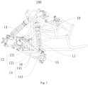
Fig. 1 is a partial perspective view of a vehicle according to an embodiment of the present disclosure. -
Fig. 2 is a side view of the vehicle shown inFig. 1 . -
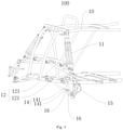
Fig. 3 is a partial perspective view of a vehicle according to another embodiment of the present disclosure. -
Fig. 4 is a side view of the vehicle shown inFig. 3 . - Embodiments of the present disclosure are described in detail below. The embodiments described with reference to accompanying drawings are exemplary.
- A vehicle according to the embodiments of the present disclosure is described below with reference to
Figs. 1-4 . Thevehicle 100 may be an all-terrain vehicle. In the following description of the present application, thevehicle 100 is described by an example in which thevehicle 100 is the all-terrain vehicle. Of course, those skilled in the art can understand that thevehicle 100 can further be other types of vehicles, rather than being limited to the all-terrain vehicle. - As shown in
Figs. 1-4 , thevehicle 100 according to the embodiments of the present disclosure may include aframe 10 and a front shock absorber 11. - Specifically, the
frame 10 can provide a mounting carrier for mounting a powertrain, a steering system, etc. of thevehicle 100, so as to ensure the stability of thewhole vehicle 100. Thefront shock absorber 11 is arranged on theframe 10, and extends obliquely backward from bottom to top. Here, it should be noted that a "front" direction can be understood as a direction of a front part of the vehicle, and an opposite direction is defined as a "rear" direction, that is, a direction of a rear part of the vehicle. - An included angle between a projection of a central axis of the front shock absorber 11 on a longitudinal central plane of the
vehicle 100 and a projection of a vertical line of the ground passing through a lower end of the front shock absorber 11 on the longitudinal central plane is α, and α meets a relation of 9°≤α≤ 20°, as shown inFig. 2 andFig. 4 . When the included angle α is less than 9°, an inclination angle of the front shock absorber 11 is relatively small, and a support force for a forward dynamic load caused by a load transfer due to a braking deceleration is poor, so that there may be an obvious phenomenon of a braking nodding. When the included angle α is greater than 20°, the inclination angle of thefront shock absorber 11 is too large, and a support force for a vertical load may be small, so that thevehicle 100 may not be well adapted to complex road conditions. - Thus, the
front shock absorber 11 is arranged to extend obliquely backward with an angle range of 9°≤α≤20°, so that the front shock absorber 11 arranged obliquely can be used to improve a support stiffness of a front suspension system when a center of gravity of thevehicle 100 transfers due to a large braking deceleration during a braking process of thevehicle 100. Therefore, the support force for the forward dynamic load caused by the load transfer due to the braking deceleration is good, an obvious effect against the braking nodding can be achieved, and thevehicle 100 can well be adapted to various road conditions (including the complex road conditions, etc.). - In the
vehicle 100 according to the embodiments of the present disclosure, the front shock absorber 11 is arranged to extend obliquely backward from bottom to top, and the included angle α between the projection of the central axis of the front shock absorber 11 on the longitudinal central plane of thevehicle 100 and the projection of the vertical line of the ground passing through the lower end of the front shock absorber 11 on the longitudinal central plane meets the relation of 9°≤α≤20°, so that the phenomenon of the braking nodding can be significantly reduced and a good effect against the braking nodding can be achieved. - According to some embodiments of the present disclosure, α can be 11°. In this way, the
vehicle 100 can achieve the good effect against the braking nodding, and also thevehicle 100 can be well adapted to various road conditions (including the complex road conditions, etc.). It can be understood that, a specific value of the included angle α can be set specifically according to actual structural design requirements of thevehicle 100. That is, α can be any angle between 9° and 20°. For example, α can also be 17° and so on. - In addition, it can be understood that the
vehicle 100 may include a front wheel and a front suspension, and the front suspension includes thefront shock absorber 11. Below, the description will be made by an example in which thevehicle 100 has two front wheels, such as a left front wheel and a right front wheel (not shown in drawings), and two front suspensions, such as a left front suspension and a right front suspension, and the left front suspension and the right front suspension are double A-arm independent suspensions (as shown inFigs. 1-4 ), but the present disclosure is not only limited tosuch vehicle 100 and double A-arm independent suspensions. For theabove vehicle 100 including the two front wheels and the two front suspensions, the left front suspension and the right front suspension may include the front shock absorber 11, respectively. The longitudinal central plane of thevehicle 100 may be defined by a central plane between the left front wheel and the right front wheel. The left front wheel and the right front wheel are rotatably connected to the left front suspension and the right front suspension, respectively, are connected to theframe 10 through the left front suspension and the right front suspension, and support theframe 10. - As shown in
Figs. 1-4 , twofront shock absorbers 11 may be provided, and the twofront shock absorbers 11 are arranged symmetrically in a left-right direction, i.e. about the longitudinal central plane of thevehicle 100. With this arrangement, the vibration of theframe 10 can be further rapidly attenuated, and the smoothness and the comfort of thevehicle 100 during driving can be improved. - According to some embodiments of the present disclosure, as shown in
Figs. 1-4 , a firstsuspension rocker arm 12 is arranged to the lower end of the front shock absorber 11, and an included angle between projections of a rotation axis of the firstsuspension rocker arm 12 and the central axis of the front shock absorber 11 on the longitudinal central plane of thevehicle 100 is denoted as β, and β meets a relation of 75°≤β≤90°. When the included angle β is less than 75°, the front shock absorber 11 may bear an excessive additional load during operation, so that thefront shock absorber 11 may be damaged because of bearing the excessive additional load. When the included angle β is greater than 90°, the front shock absorber will be inclined forward, thus aggravating the nodding phenomenon. This arrangement can ensure that the front shock absorber 11 will not bear the excessive additional load during operation, so as to prolong the service life of the front shock absorber 11. - In some embodiments, β is 90°. This arrangement can ensure that the
front shock absorber 11 can bear a minimum additional load while achieving the good effect against the braking nodding, thus further prolonging the service life of thefront shock absorber 11. Of course, it can be understood that, β can be any angle between 75° and 90°. For example, β can also be 78° and so on. - According to some specific embodiments of the present disclosure, as shown in
Fig. 1 , the firstsuspension rocker arm 12 includes twofirst rocking rods 121, first ends of the twofirst rocking rods 121 are connected and rotatably connected to the lower end of the front shock absorber 11 (for example, connected by an joint bearing, but not limited to this), and second ends of the twofirst rocking rods 121 are pivotally connected to theframe 10, respectively (for example, connected by an joint bearing, but not limited to this). A pivot axis of each of the second ends of the twofirst rocking rods 121 is a rotation axis of the firstsuspension rocker arm 12. With this arrangement, when the wheels steer, the two rockingrods 121 can absorb a lateral force applied to a tire, and thus an inclination of the vehicle when steering is small. In addition, the two rockingrods 121 can pivot relative to theframe 10, so as to prevent connection portions between the two rockingrods 121 and theframe 10 from being broken because of bearing an excessive force when thevehicle 100 is driving on a rough road. Similarly, the rotatable connection between the first ends of the twofirst rocking rods 121 and the lower end of thefront shock absorber 11 also prevents connection portions between the twofirst rocking rods 121 and thefront shock absorber 11 from being broken because of bearing an excessive force. - Further, referring to
Fig. 1 , a first connectingrod 13 may be connected between the twofirst rocking rods 121. The twofirst rocking rods 121 and the first connectingrod 13 are substantially in an "A" shape. Thus, by arranging the first connectingrod 13 between the twofirst rocking rods 121, the connecting stability of the twofirst rocking rods 121 can be strengthened and the structural strength of the firstsuspension rocker arm 12 can be improved. - In some embodiments, referring to
Fig. 1 , the first connectingrod 13 may be connected to a portion of each of the twofirst rocking rods 121 adjacent to the rotation axis of the firstsuspension rocker arm 12, so as to further improve the connecting stability of the twofirst rocking rods 121. Of course, two ends of the first connectingrod 13 can be arranged at any position between respective two ends of the twofirst rocking rods 121, respectively. - It can be understood that a number of the first connecting
rods 13 can be set specifically according to actual requirements, so as to better satisfy the practical applications. - According to a further embodiment of the present disclosure, referring to
Fig. 1 , a secondsuspension rocker arm 14 is arranged below the firstsuspension rocker arm 12, a first end of the secondsuspension rocker arm 14 is rotatably connected to the first ends of the twofirst rocking rods 121 through asteering knuckle 15, and a second end of the secondsuspension rocker arm 14 is pivotally connected to the frame 10 (for example, connected by a joint bearing, but not limited to this). Thus, when the front wheels steer, the firstsuspension rocker arm 12 and the secondsuspension rocker arm 14 arranged one above the other can absorb the lateral force applied to the tire simultaneously, and thus the inclination of the vehicle when steering is small. In addition, the secondsuspension rocker arm 14 can pivot relative to theframe 10, so as to prevent a connection portion between the secondsuspension rocker arm 14 and theframe 10 from being broken because of bearing an excessive force when thevehicle 100 is driving on a rough road. Similarly, the first end of the secondsuspension rocker arm 14 is rotatably connected to the first ends of the twofirst rocking rods 121, so as to prevent connection portions between the secondsuspension rocker arm 14 and the twofirst rocking rods 121 from being broken because of bearing an excessive force. - Further, still referring to
Fig. 1 , the secondsuspension rocker arm 14 also includes twosecond rocking rods 141, first ends of the twosecond rocking rods 141 are rotatably connected to thesteering knuckle 15, and second ends of the twosecond rocking rods 141 are pivotally connected to theframe 10, respectively. This arrangement prevents connection portions between the twosecond rocking rods 141 and theframe 10 from being broken because of bearing an excessive force when thevehicle 100 is driving on a rough road. - Further, referring to
Fig. 1 andFig. 3 , a second connectingrod 16 may be connected between the twosecond rocking rods 141, and two ends of the second connectingrod 16 are located between respective two ends of the twosecond rocking rods 141, respectively. The twosecond rocking rods 141 and the second connectingrod 16 are substantially in an "A" shape. Therefore, by arranging the second connectingrod 16 between the twosecond rocking rods 141, the connecting stability of the twosecond rocking rods 141 can be strengthened and the structural strength of the secondsuspension rocker arm 14 can be improved. - Further, two or more second connecting
rods 16 may be arranged between the twosecond rocking rods 141 to enhance the connecting stability between thesecond rocking rods 141. For example, two second connectingrods 16 are arranged between the twosecond rocking rods 141 of the secondsuspension rocker arm 14 shown inFig. 3 . - In some embodiments, referring to
Fig. 1 , the second connectingrod 16 may be connected to a portion of each of the twosecond rocking rods 141 adjacent to the second end of each of the twosecond rocking rods 141, so as to further improve the connecting stability of the twosecond rocking rods 141. In some embodiments, as shown inFig. 3 , the second connectingrod 16 may also be connected to a portion of each of the twosecond rocking rods 141 adjacent to the first end of each of the twosecond rocking rods 141, so as to further improve the connecting stability of the twosecond rocking rods 141. - Of course, the two ends of the second connecting
rod 16 can be arranged at any position between respective two ends of the twosecond rocking rods 141, respectively. - It can be understood that a number of the second connecting
rods 16 can be set specifically according to actual requirements, so as to better satisfy the practical applications. - Other configurations and operations of the
vehicle 100 according to the embodiments of the present disclosure are known to those skilled in the art, and will not be described in detail here. - In the description of the present disclosure, it is to be understood that terms such as "central," "upper," "lower," "front," "left," "right," "vertical," "horizontal," "top," "bottom," "inner," "outer," "axial," should be construed to refer to the orientation or position as then described or as shown in the drawings under discussion. These relative terms are for convenience of description of the present disclosure and do not indicate or imply that the device or element referred to must have a particular orientation, or be constructed and operated in a particular orientation. Thus, these terms shall not be construed as limitation on the present disclosure.
- Reference throughout this specification to "some embodiments," "an exemplary embodiment," "an example," or "some examples," means that a particular feature, structure, material, or characteristic described in connection with the embodiment or example is included in at least one embodiment or example of the present disclosure. Thus, the exemplary descriptions of the above terms throughout this specification are not necessarily referring to the same embodiment or example.
- Although embodiments of the present disclosure have been shown and described, it would be appreciated by those skilled in the art that various changes, modifications, alternatives and variations may be made in the embodiments without departing from principles and purposes of the present disclosure. The scope of the present disclosure is defined by the claims and their equivalents.
Claims (15)
- A vehicle (100), comprising:a frame (10); anda front shock absorber (11) arranged to the frame (10) and extends obliquely backward from bottom to top, wherein an included angle between a projection of a central axis of the front shock absorber (11) on a longitudinal central plane of the vehicle (100) and a projection of a vertical line of the ground passing through a lower end of the front shock absorber (11) on the longitudinal central plane is denoted as α,and α meets a relation of 9°≤α≤20°.
- The vehicle (100) according to claim 1, wherein α is 11°.
- The vehicle (100) according to claim 1 or 2, wherein two front shock absorbers (11) are provided, and the two front shock absorbers (11) are arranged symmetrically in a left-right direction.
- The vehicle (100) according to any one of claims 1 to 3, wherein a first suspension rocker arm (12) is arranged to the lower end of the front shock absorber (11), and an included angle between projections of a rotation axis of the first suspension rocker arm (12) and the central axis of the front shock absorber (11) on the longitudinal central plane of the vehicle (100) is denoted as β, and β meets a relation of 75°≤β≤90°.
- The vehicle (100) according to claim 4, wherein β is 90°.
- The vehicle (100) according to claim 4 or 5, wherein the first suspension rocker arm (12) comprises two first rocking rods (121), first ends of the two first rocking rods (121) are connected and rotatably connected to the lower end of the front shock absorber (11), second ends of the two first rocking rods (121) are pivotally connected to the frame (10), respectively, and a pivot axis of the second end of each of the two first rocking rods (121) is the rotation axis of the first suspension rocker arm (12).
- The vehicle (100) according to claim 6, wherein a first connecting rod (13) is connected between the two first rocking rods (121).
- The vehicle (100) according to claim 7, wherein the two first rocking rods (121) and the first connecting rod (13) are in an "A" shape.
- The vehicle (100) according to claim 7 or 8, wherein the first connecting rod (13) is connected to a portion of each of the two first rocking rods (121) adjacent to the rotation axis of the first suspension rocker arm (12).
- The vehicle (100) according to any one of claims 6 to 9, wherein a second suspension rocker arm (14) is arranged below the first suspension rocker arm (12), a first end of the second suspension rocker arm (14) is rotatably connected to the first ends of the two first rocking rods (121) through a steering knuckle (15), and a second end of the second suspension rocker arm (14) is pivotally connected to the frame (10).
- The vehicle (100) according to claim 10, wherein the second suspension rocker arm (14) comprises two second rocking rods (141), first ends of the two second rocking rods (141) are rotatably connected to the steering knuckle (15), and second ends of the two second rocking rods (141) are pivotally connected to the frame (10), respectively.
- The vehicle (100) according to claim 11, wherein a second connecting rod (16) is connected between the two second rocking rods (141).
- The vehicle (100) according to claim 12, wherein the two second rocking rods (141) and the second connecting rod (16) are in an "A" shape.
- The vehicle (100) according to claim 12 or 13, wherein the second connecting rod (16) is connected to a portion of each of the two second rocking rods (141) adjacent to the first end of each of the two second rocking rods (141); or
the second connecting rod (16) is connected to a portion of each of the two second rocking rods (141) adjacent to the second end of each of the two second rocking rods (141). - The vehicle (100) according to any one of claims 1 to 14, wherein the vehicle (100) is an all-terrain vehicle (100).
Applications Claiming Priority (1)
| Application Number | Priority Date | Filing Date | Title |
|---|---|---|---|
| CN202022025509.5U CN213861761U (en) | 2020-09-15 | 2020-09-15 | Vehicle with a steering wheel |
Publications (1)
| Publication Number | Publication Date |
|---|---|
| EP3967529A1 true EP3967529A1 (en) | 2022-03-16 |
Family
ID=77048618
Family Applications (1)
| Application Number | Title | Priority Date | Filing Date |
|---|---|---|---|
| EP21195653.7A Withdrawn EP3967529A1 (en) | 2020-09-15 | 2021-09-09 | All terrain vehicle suspension |
Country Status (4)
| Country | Link |
|---|---|
| US (1) | US20220080796A1 (en) |
| EP (1) | EP3967529A1 (en) |
| CN (1) | CN213861761U (en) |
| CA (1) | CA3130783A1 (en) |
Families Citing this family (8)
| Publication number | Priority date | Publication date | Assignee | Title |
|---|---|---|---|---|
| US9205717B2 (en) | 2012-11-07 | 2015-12-08 | Polaris Industries Inc. | Vehicle having suspension with continuous damping control |
| CN107406094B (en) | 2014-10-31 | 2020-04-14 | 北极星工业有限公司 | System and method for controlling a vehicle |
| CA3043481C (en) | 2016-11-18 | 2022-07-26 | Polaris Industries Inc. | Vehicle having adjustable suspension |
| US10406884B2 (en) | 2017-06-09 | 2019-09-10 | Polaris Industries Inc. | Adjustable vehicle suspension system |
| US10987987B2 (en) | 2018-11-21 | 2021-04-27 | Polaris Industries Inc. | Vehicle having adjustable compression and rebound damping |
| MX2022015902A (en) | 2020-07-17 | 2023-01-24 | Polaris Inc | Adjustable suspensions and vehicle operation for off-road recreational vehicles. |
| US11718134B1 (en) * | 2022-04-22 | 2023-08-08 | Kawasaki Motors, Ltd. | Vehicle |
| WO2023232009A1 (en) * | 2022-05-30 | 2023-12-07 | 浙江春风动力股份有限公司 | All-terrain vehicle |
Citations (5)
| Publication number | Priority date | Publication date | Assignee | Title |
|---|---|---|---|---|
| EP1559594A2 (en) * | 2004-01-30 | 2005-08-03 | HONDA MOTOR CO., Ltd. | Drive shaft protector for a saddle ride type all-terrain vehicle |
| WO2015114606A1 (en) * | 2014-01-31 | 2015-08-06 | Bombardier Recreational Products Inc. | Off-road wheeled side-by-side vehicle |
| WO2018033768A1 (en) * | 2016-08-15 | 2018-02-22 | Bombardier Recreational Products Inc. | Rear suspension assembly for an off-road vehicle |
| US20190291523A1 (en) * | 2018-03-22 | 2019-09-26 | Yamaha Hatsudoki Kabushiki Kaisha | Vehicle |
| US20200130450A1 (en) * | 2018-03-27 | 2020-04-30 | Kawasaki Jukogyo Kabushiki Kaisha | Supporting structure for shock absorber of suspension device and suspension structure of utility vehicle |
Family Cites Families (4)
| Publication number | Priority date | Publication date | Assignee | Title |
|---|---|---|---|---|
| DE102007005967A1 (en) * | 2007-02-07 | 2008-08-14 | Audi Ag | Suspension for motor vehicles |
| IL191176A0 (en) * | 2008-04-30 | 2008-12-29 | Afikim Electric Vehicles | Wheels suspension system for vehicles |
| US8740232B2 (en) * | 2012-02-03 | 2014-06-03 | Daniel Kunau | Offset inclined suspension |
| CN108136897A (en) * | 2015-07-30 | 2018-06-08 | 庞巴迪动力产品公司 | For the knuckle of vehicle suspension assembly |
-
2020
- 2020-09-15 CN CN202022025509.5U patent/CN213861761U/en active Active
-
2021
- 2021-09-09 EP EP21195653.7A patent/EP3967529A1/en not_active Withdrawn
- 2021-09-14 US US17/474,107 patent/US20220080796A1/en not_active Abandoned
- 2021-09-14 CA CA3130783A patent/CA3130783A1/en not_active Abandoned
Patent Citations (5)
| Publication number | Priority date | Publication date | Assignee | Title |
|---|---|---|---|---|
| EP1559594A2 (en) * | 2004-01-30 | 2005-08-03 | HONDA MOTOR CO., Ltd. | Drive shaft protector for a saddle ride type all-terrain vehicle |
| WO2015114606A1 (en) * | 2014-01-31 | 2015-08-06 | Bombardier Recreational Products Inc. | Off-road wheeled side-by-side vehicle |
| WO2018033768A1 (en) * | 2016-08-15 | 2018-02-22 | Bombardier Recreational Products Inc. | Rear suspension assembly for an off-road vehicle |
| US20190291523A1 (en) * | 2018-03-22 | 2019-09-26 | Yamaha Hatsudoki Kabushiki Kaisha | Vehicle |
| US20200130450A1 (en) * | 2018-03-27 | 2020-04-30 | Kawasaki Jukogyo Kabushiki Kaisha | Supporting structure for shock absorber of suspension device and suspension structure of utility vehicle |
Also Published As
| Publication number | Publication date |
|---|---|
| US20220080796A1 (en) | 2022-03-17 |
| CA3130783A1 (en) | 2022-03-15 |
| CN213861761U (en) | 2021-08-03 |
Similar Documents
| Publication | Publication Date | Title |
|---|---|---|
| EP3967529A1 (en) | All terrain vehicle suspension | |
| US5697633A (en) | Suspension system of front wheels for a vehicle | |
| US5498018A (en) | Wheel suspension | |
| US4799708A (en) | Off-road vehicle | |
| JPH0450166Y2 (en) | ||
| CN104520178B (en) | For with two can lateral tilt front-wheel vehicle steering spindle | |
| JP6803234B2 (en) | Vehicle suspension | |
| RU2517274C2 (en) | Independent suspension of transport facility | |
| US5421606A (en) | Steerable front wheel suspension for vehicle | |
| JPS6164506A (en) | Strut type suspension | |
| KR910008158B1 (en) | Rear suspension apparatus | |
| WO1995012499A1 (en) | Suspension system for a vehicle | |
| US4986565A (en) | Wheel suspension system for vehicles | |
| CN115707584B (en) | Multi-connecting rod rear suspension assembly and automobile | |
| JPS6053408A (en) | Rear suspension of car | |
| US12350994B2 (en) | Suspension and off-road vehicle | |
| US3279556A (en) | Vehicle suspension system | |
| JPS63134389A (en) | Front-wheel suspension system for four-wheel buggy car | |
| KR100316892B1 (en) | Lower control arm of suspension system for vehicle | |
| CN222591149U (en) | Rear suspension system and vehicle | |
| JPH11151922A (en) | Suspension device for axle | |
| CN206086248U (en) | Car, chassis and suspension thereof | |
| JP2006117045A (en) | Front suspension device for automobile | |
| US20230029991A1 (en) | Vehicle | |
| JPH0737928Y2 (en) | Car rear wheel suspension |
Legal Events
| Date | Code | Title | Description |
|---|---|---|---|
| PUAI | Public reference made under article 153(3) epc to a published international application that has entered the european phase |
Free format text: ORIGINAL CODE: 0009012 |
|
| STAA | Information on the status of an ep patent application or granted ep patent |
Free format text: STATUS: THE APPLICATION HAS BEEN PUBLISHED |
|
| AK | Designated contracting states |
Kind code of ref document: A1 Designated state(s): AL AT BE BG CH CY CZ DE DK EE ES FI FR GB GR HR HU IE IS IT LI LT LU LV MC MK MT NL NO PL PT RO RS SE SI SK SM TR |
|
| STAA | Information on the status of an ep patent application or granted ep patent |
Free format text: STATUS: REQUEST FOR EXAMINATION WAS MADE |
|
| 17P | Request for examination filed |
Effective date: 20220720 |
|
| RBV | Designated contracting states (corrected) |
Designated state(s): AL AT BE BG CH CY CZ DE DK EE ES FI FR GB GR HR HU IE IS IT LI LT LU LV MC MK MT NL NO PL PT RO RS SE SI SK SM TR |
|
| STAA | Information on the status of an ep patent application or granted ep patent |
Free format text: STATUS: EXAMINATION IS IN PROGRESS |
|
| 17Q | First examination report despatched |
Effective date: 20221110 |
|
| STAA | Information on the status of an ep patent application or granted ep patent |
Free format text: STATUS: THE APPLICATION IS DEEMED TO BE WITHDRAWN |
|
| 18D | Application deemed to be withdrawn |
Effective date: 20230321 |