EP3967421A1 - Methods for casting a component having a readily removable casting core - Google Patents
Methods for casting a component having a readily removable casting core Download PDFInfo
- Publication number
- EP3967421A1 EP3967421A1 EP21193243.9A EP21193243A EP3967421A1 EP 3967421 A1 EP3967421 A1 EP 3967421A1 EP 21193243 A EP21193243 A EP 21193243A EP 3967421 A1 EP3967421 A1 EP 3967421A1
- Authority
- EP
- European Patent Office
- Prior art keywords
- core
- casting
- component
- mold
- cavity
- Prior art date
- Legal status (The legal status is an assumption and is not a legal conclusion. Google has not performed a legal analysis and makes no representation as to the accuracy of the status listed.)
- Granted
Links
Images



Classifications
-
- B—PERFORMING OPERATIONS; TRANSPORTING
- B22—CASTING; POWDER METALLURGY
- B22C—FOUNDRY MOULDING
- B22C9/00—Moulds or cores; Moulding processes
- B22C9/22—Moulds for peculiarly-shaped castings
-
- B—PERFORMING OPERATIONS; TRANSPORTING
- B22—CASTING; POWDER METALLURGY
- B22C—FOUNDRY MOULDING
- B22C9/00—Moulds or cores; Moulding processes
- B22C9/10—Cores; Manufacture or installation of cores
-
- B—PERFORMING OPERATIONS; TRANSPORTING
- B22—CASTING; POWDER METALLURGY
- B22D—CASTING OF METALS; CASTING OF OTHER SUBSTANCES BY THE SAME PROCESSES OR DEVICES
- B22D29/00—Removing castings from moulds, not restricted to casting processes covered by a single main group; Removing cores; Handling ingots
- B22D29/001—Removing cores
- B22D29/002—Removing cores by leaching, washing or dissolving
-
- B—PERFORMING OPERATIONS; TRANSPORTING
- B22—CASTING; POWDER METALLURGY
- B22C—FOUNDRY MOULDING
- B22C9/00—Moulds or cores; Moulding processes
- B22C9/02—Sand moulds or like moulds for shaped castings
-
- B—PERFORMING OPERATIONS; TRANSPORTING
- B22—CASTING; POWDER METALLURGY
- B22C—FOUNDRY MOULDING
- B22C9/00—Moulds or cores; Moulding processes
- B22C9/10—Cores; Manufacture or installation of cores
- B22C9/106—Vented or reinforced cores
-
- B—PERFORMING OPERATIONS; TRANSPORTING
- B28—WORKING CEMENT, CLAY, OR STONE
- B28B—SHAPING CLAY OR OTHER CERAMIC COMPOSITIONS; SHAPING SLAG; SHAPING MIXTURES CONTAINING CEMENTITIOUS MATERIAL, e.g. PLASTER
- B28B1/00—Producing shaped prefabricated articles from the material
- B28B1/001—Rapid manufacturing of 3D objects by additive depositing, agglomerating or laminating of material
-
- B—PERFORMING OPERATIONS; TRANSPORTING
- B28—WORKING CEMENT, CLAY, OR STONE
- B28B—SHAPING CLAY OR OTHER CERAMIC COMPOSITIONS; SHAPING SLAG; SHAPING MIXTURES CONTAINING CEMENTITIOUS MATERIAL, e.g. PLASTER
- B28B7/00—Moulds; Cores; Mandrels
- B28B7/34—Moulds, cores, or mandrels of special material, e.g. destructible materials
- B28B7/346—Manufacture of moulds
-
- B—PERFORMING OPERATIONS; TRANSPORTING
- B33—ADDITIVE MANUFACTURING TECHNOLOGY
- B33Y—ADDITIVE MANUFACTURING, i.e. MANUFACTURING OF THREE-DIMENSIONAL [3D] OBJECTS BY ADDITIVE DEPOSITION, ADDITIVE AGGLOMERATION OR ADDITIVE LAYERING, e.g. BY 3D PRINTING, STEREOLITHOGRAPHY OR SELECTIVE LASER SINTERING
- B33Y80/00—Products made by additive manufacturing
-
- B—PERFORMING OPERATIONS; TRANSPORTING
- B33—ADDITIVE MANUFACTURING TECHNOLOGY
- B33Y—ADDITIVE MANUFACTURING, i.e. MANUFACTURING OF THREE-DIMENSIONAL [3D] OBJECTS BY ADDITIVE DEPOSITION, ADDITIVE AGGLOMERATION OR ADDITIVE LAYERING, e.g. BY 3D PRINTING, STEREOLITHOGRAPHY OR SELECTIVE LASER SINTERING
- B33Y10/00—Processes of additive manufacturing
-
- F—MECHANICAL ENGINEERING; LIGHTING; HEATING; WEAPONS; BLASTING
- F05—INDEXING SCHEMES RELATING TO ENGINES OR PUMPS IN VARIOUS SUBCLASSES OF CLASSES F01-F04
- F05D—INDEXING SCHEME FOR ASPECTS RELATING TO NON-POSITIVE-DISPLACEMENT MACHINES OR ENGINES, GAS-TURBINES OR JET-PROPULSION PLANTS
- F05D2230/00—Manufacture
- F05D2230/20—Manufacture essentially without removing material
- F05D2230/21—Manufacture essentially without removing material by casting
- F05D2230/211—Manufacture essentially without removing material by casting by precision casting, e.g. microfusing or investment casting
-
- Y—GENERAL TAGGING OF NEW TECHNOLOGICAL DEVELOPMENTS; GENERAL TAGGING OF CROSS-SECTIONAL TECHNOLOGIES SPANNING OVER SEVERAL SECTIONS OF THE IPC; TECHNICAL SUBJECTS COVERED BY FORMER USPC CROSS-REFERENCE ART COLLECTIONS [XRACs] AND DIGESTS
- Y02—TECHNOLOGIES OR APPLICATIONS FOR MITIGATION OR ADAPTATION AGAINST CLIMATE CHANGE
- Y02P—CLIMATE CHANGE MITIGATION TECHNOLOGIES IN THE PRODUCTION OR PROCESSING OF GOODS
- Y02P10/00—Technologies related to metal processing
- Y02P10/25—Process efficiency
Definitions
- the present subject matter relates generally to the production of components for gas turbine engines, and more particularly, to a removable casting core and method of manufacturing.
- Gas turbine engine components such as turbine airfoils, are frequently manufactured using an investment casting process in which molten metal alloy is introduced into a mold cavity defined between a shell and a core and allowed to solidify, forming a completed casting.
- a time-consuming step in the manufacturing process is removal of the core after the casting is complete.
- the removal of the core after casting often involves leaching out the core material with a caustic solution (usually aqueous sodium hydroxide or potassium hydroxide for ceramic cores).
- a caustic solution usually aqueous sodium hydroxide or potassium hydroxide for ceramic cores.
- this challenge will be magnified as higher temperature, yttrium-containing alloys are used, requiring non-reactive casting core materials such as alumina- and zirconia-based ceramics. These core materials leach much more slowly than silica-based materials currently in use.
- the present disclosure is directed to a method for casting a component.
- the method may include providing a casting core within a cavity of a component mold.
- the cavity of the component mold may define an outer component shape and the casting core may define an inner component shape.
- the casting core may include a core wall.
- the core wall may define a core outer surface and a core inner surface disposed opposite the core outer surface.
- the core inner surface may define a core cavity and the casting core may include a removal facilitation feature.
- the method may also include casting the component within the cavity of the component mold with the casting core positioned therein. Additionally, the method may include removing the cast component from the component mold, with the casting core positioned internally within the component. The method may further include removing the casting core from the cast component.
- first, second, and third may be used interchangeably to distinguish one component from another and are not intended to signify location or importance of the individual components.
- upstream and downstream refer to the relative direction with respect to fluid flow in a fluid pathway.
- upstream refers to the direction from which the fluid flows
- downstream refers to the direction to which the fluid flows.
- the present subject matter is directed to a method for forming a cast component.
- the method may include a number of processes each of which may also be a method. These processes may include the casting of the component and the formation of the casting core to be used in the component casting process.
- the casting core may be formed by various manufacturing methods including casting and additive manufacturing.
- the casting core may be formed with removal facilitation features, which enable the casting core to be more easily removed from the cast component.
- the removal facilitation features may include cavities, support webs, or easily-removable sub-cores.
- the removal facilitation features enable a leaching solution to contact a greater surface area of the casting core at one time then would be accessible using known techniques. With a greater surface area of the casting core being affected at once, the casting core may be more quickly removed from the cast component.
- FIG. 1 illustrates a cross-sectional view of one embodiment of a gas turbine engine 100 that may be utilized with an aircraft in accordance with aspects of the present subject matter.
- Various components of the gas turbine engine 100 may be formed via the methods for casting a component disclosed herein.
- the engine 100 is shown having a longitudinal or axial centerline axis 112 extending therethrough for reference purposes.
- the engine 100 will be discussed in detail below.
- the methods described herein may be used on any turbomachine including, but not limited to, high-bypass turbofan engines, low-bypass turbofan engines, turbojet engines, turboprop engines, turboshaft engines, propfan engines, and so forth.
- the turbomachine may be configured in any suitable manner, such as for vehicle propulsion or ground-based power production.
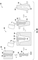
- FIGS. 2A-2B illustrate schematic views of a method 200 for forming a cast component 202.
- the method 200 for forming a cast component 202 may include a plurality of processes, each of which, may also be a method.
- the method 200 may include a core-formation method 300 or 301 and a component casting process 400.
- the method 200 may generally include the steps of forming a casting core 302 via the core-formation method 300 or 301 and providing the casting core 302 within a cavity 402 of a component mold 404.
- the cast component 202 may be cast within the cavity 402.
- the casting core 302 may then be removed from the cast component 202.
- the cast component 202 is a turbine engine component of the gas turbine engine 100. It should be appreciated that the progression of steps, or processes, in the method 200 for forming a cast component 202 is represented in FIG. 2A by arrows A-D and in FIG. 2B by arrows A-C. As shown, the method 200 may include two distinct molds, the component mold 404 used in the component casting process 400 and a core mold 304 used in method 300, and the casting core 302 produced using the core mold 304 may be positioned subsequently into the component mold 404.
- the method 200 may use only a single mold, the component mold 404 in the component casting process 400, and the casting core 302 may be provided to the component mold 404 by simultaneously forming the casting core 302 and component mold 404 via an additive manufacturing device 303 by an additive manufacturing method 301 in FIG. 2B .
- two distinct cores may be used, the casting core 302 and a sub-core 324 ( FIGS. 4A-4B ), wherein the sub-core 324 may be separately formed and positioned in the casting core 302 or may be simultaneously formed with the casting core 302.
- the core-formation method 300 may include the core mold 304.
- the core mold 304 may be formed with a core mold inner face 306, which is the negative of a casting core outer shape 308.
- the casting core 302 may be a hollow core and may comprise a core wall 310 defining a core outer surface 312 and a core inner surface ( FIG. 3B , 314) disposed opposite the core outer surface 312.
- the core inner surface 314 may define a core cavity ( FIG. 3B , 316).
- the casting core 302 may also include a removal facilitation feature ( FIG. 3B , 318), as will be discussed in more detail below. It should be appreciated that the inclusion of the core mold 304 in FIG. 2A is not intended to limit the core-formation method 300 to a particular manufacturing method, such as casting.
- the casting core 302 may be formed by any suitable manufacturing method.
- the casting core 302 may be an additive manufacturing product, thereby eliminating Step A in FIG. 2A .
- the casting core 302 may be separately produced by additive manufacturing and positioned into the component mold 404 as in FIG. 2B , or both the casting core 302 and component mold 404 may be an additive manufacturing product, produced simultaneously.
- the casting core 302 may be constructed from a refractory material capable of maintaining structural integrity when exposed to molten metal alloys at high temperatures.
- the core may be formed from a solid ceramic material.
- Ceramics include those based on silica, alumina, calcium, magnesium, zirconia, and other refractory oxides. Materials such as alumina- and zirconia-based ceramics are considered nonreactive with certain metal alloys.
- the casting core 302 may be constructed of a core material (Mc) that may be brittle between 1314°C and 21°C.
- the component casting process 400 may include a component mold 404 that may define a cavity 402.
- the cavity 402 may define an outer component shape 204 of the cast component 202.
- the casting core 302 may be provided within the cavity 402 of the component mold 404 so that the casting core 302 defines an inner component shape 206.
- molten component material (C M ) may be introduced into the component mold 404 to form the cast component 202.
- the cast component 202, with the casting core 302 positioned internally within the cast component 202 may be removed from the component mold 404.
- a caustic leaching solution may be applied to the casting core 302 to leach the casting core 302 from within the cast component 202.
- the caustic leaching solution (Ls) must be brought into contact with the casting core 302.
- the amount of surface area of the casting core 302 that may be affected by the leaching solution (Ls) at any given time may affect the rate at which the leaching process proceeds.
- the removal facilitation feature 318 may be a feature of the casting core 302 that increases the amount of surface area of the casting core 302 that may be affected by the leaching solution (Ls) at any given time.
- a water jet may be employed to remove the casting core 302 from within the cast component 202.
- the greater the surface area of the casting core 302 that may be subjected to the waterjet the more effective the waterjet may be at removing the casting core 302 from the cast component 202.
- the casting core 302 may be subjected to a vibration. In such an embodiment, an increase in surface area of the casting core 302 may permit a greater vibrational movement of the casting core 302, which may lead to the fracturing and removal of the casting core 302.
- FIG. 3A illustrates a schematic cross-sectional view of an embodiment of a method for forming a casting core for use in the exemplary method 200.
- the core-formation method 300 may include an injection apparatus 320.
- the injection apparatus 320 may be inserted into the core mold 304.
- the injection apparatus 320 may deposit one or more layers 322 of core material (Mc) on the core mold inner face 306 to form the core wall 310.
- the injection apparatus 320 may deposit sufficient core material (Mc) to establish a core wall thickness (T) of 0.1 mm to 5 mm.
- the casting core 302 may have a core wall 310 comprising a single core layer 322 having the core wall thickness (T) of 0.1 mm to 5 mm.
- the core wall 310 may comprise a plurality of core layers 322 to establish the core wall thickness (T) of 0.1 mm to 5 mm.
- the core wall thickness (T) may be 0.1 mm to 4 mm, 0.5 mm to 4 mm, 0.5 mm to 2.5 mm, 0.1 mm to 2.5 mm, 1 mm to 3 mm, or 2 mm to 4 mm. It should be appreciated that, in at least one embodiment, the thickness (T) may be the removal facilitation feature 318.
- the thickness (T) may be selected to ensure the casting core 302 is of sufficient strength to resist compression as the cast component 202 is cast, while minimizing the amount of core material (Mc) to be removed and maximizing the amount of surface area of the casting core 302 that may be affected by the leaching solution (Ls) at any given time.
- the core wall 310 may comprise a plurality of core layers 322.
- the injection apparatus 320 may deposit successive core layers 322 until the core wall thickness (T), e.g., 0.1 mm to 5 mm, is achieved.
- T core wall thickness
- the injection apparatus 320 may be inserted into the core mold 304 and may deposit a core layer 322 as the injection apparatus 320 is withdrawn from the core mold 304.
- the injection apparatus 320 may then be reinserted into the core mold 304 and may deposit an additional core layer 322 as the injection apparatus 320 is again withdrawn from the core mold 304.
- the process of inserting the injection apparatus 320 and depositing a core layer 322 may be repeated until the core wall thickness (T), e.g., 0.1 mm to 5 mm, is achieved.
- the removal facilitation feature 318 may include structures and materials that may serve to make the casting core 302 more susceptible to known removal processes.
- the core wall 310 may have sufficient strength to resist deformation during the component casting process 400 and, thus, the core cavity 316 may be formed without the inclusion of any additional support elements.
- the entirety of the surface area of the core inner surface 314 may be simultaneously exposed to known leaching processes.
- the casting core 302 may include, within the core cavity 316, additional support structures as may be necessary to reduce, or eliminate, deformation of the casting core 302 during the casting process.
- the removal facilitation features 318 may include filling the core cavity 316 with a highly-removable sub-core or a support web to provide structural support while maintaining a maximal surface area that may be instantly exposed to a removal process, such as leaching.
- FIG. 4A illustrates a schematic cross-sectional view of one embodiment of a method for forming a casting core, which may have a sub-core, for use in the exemplary method 200.
- the core-formation method 300 may include a sub-core 324 comprising a sub-core material 326.
- the core mold 304 may be formed with a core mold inner face 306 that is the negative of a casting core outer shape 308.
- the sub-core 324 may be secured within the core mold 304 and a portion of core material (Mc) may be introduced into the core mold 304 to form the core wall 310 as a single core layer 322.
- Mc core material
- the sub-core material 326 may comprise an easily removable material yet possess sufficient rigidity to provide structural support to the casting core 302.
- the sub-core 324 may be easily removable, and may be the removal facilitation feature 318 within the core cavity 316.
- the sub-core 324 may be maintained in the casting core 302 until the cast component 202 is cast. Once the cast component 202 is cast, the sub-core 324 may be exposed to rapid leaching and removed from the casting core 302. The rapid leaching of the sub-core 324 may expose a greater surface area of the casting core 302 to the leaching process.
- the casting core 302 may be formed by any of the methods described herein, wherein the casting core 302 is formed with the core cavity 316.
- the sub-core 324 comprising the sub-core material 326, may be formed separately and inserted into the core cavity 316.
- the casting core 302 may have a core wall thickness (T) of 0.1 mm to 5 mm and may be structurally supported by the spanning of the core cavity 316 by the sub-core 324. Because the sub-core material 326 may be an easily removable material, the sub-core 324 may be the removal facilitation feature 318 within the core cavity 316.
- multi-material additive manufacturing may be used to form the casting core 302, sub-core 324, and component mold 404 simultaneously.
- the casting core 302 with the sub-core 324 therein may thus be provided to the component mold 404 simultaneously with formation of the component mold 404.
- the cavity 402 may include one or more features (not shown) connecting the casting core 302 to the component mold, which may serve as support structures during casting, and which may leach out to form features, such as holes and passages, in the cast component 202.
- the sub-core 324 may be formed separately and thereafter inserted into the additively manufactured casting core 302 and component mold 404 to provide support during the subsequent component casting process 400.
- FIGs. 5A, 5B , 5C , and 6 illustrate schematic top views of embodiments of a method for forming a casting core, which may have a support web, for use in the exemplary method 200.
- the core formation methods 300 and 301 may include a support web 328 contained within the core cavity 316 and coupled to the core inner surface 314.
- the support web 328 may be a removal facilitation feature 318 within the core cavity 316.
- the support web 328 may comprise a plurality of pores, cavities, or voids 330.
- the plurality of pores, cavities, or voids 330 may facilitate penetration of a caustic leaching solution (Ls) during core removal.
- Ls caustic leaching solution
- the support web 328 permits the penetration of the caustic leaching solution (Ls), maximal surface area of the core inner surface 314 may be exposed to the leaching process at once.
- the plurality of pores, cavities, or voids 330 may increase the effectiveness of other core removal methods, such as a water jet or vibration.
- the support web 328 may be configured to provide structural support for the core 302.
- the support web 328 may ensure mechanical support is provided in areas subject to high stress during the component casting process 400.
- the support web 328 may also limit or control thermal expansion of the core 302 during the casting process.
- the support web 328 may take any suitable form including a plurality of support members 332, a single structural member 334, or a foam ( FIG. 6 , 336). It should be appreciated that the web 328 may be formed from the core material (Mc), the sub-core material 326, or other suitable material.
- the support web 328 may comprise a plurality of support members 332.
- the plurality of support members 332 may span the core cavity 316 and be coupled to the core inner surface 314. At least two support members of the plurality of support members 332 may meet at an intersection 338.
- the plurality of support members 332 may be arranged in a repeating pattern to form a lattice structure having a plurality of intersections 338.
- the plurality of support members 332 may intersect the core inner surface 314 at specific locations where a high stress load is computed.
- the location having a high stress load may be a gradient peak having a stress concentration value which is greater than the stress concentration of at least one adjacent region.
- the arrangement of the plurality of support members 332 may have no discernible pattern and may not include the intersection 338.
- the plurality of support members 332 may comprise a plurality of beams.
- the plurality of support members 332 may comprise a plurality of dividers or walls extending. Each divider or wall may be a unitary structure extending substantially along the core inner surface. For example, in at least one embodiment, each divider wall may have an edge length substantially equal to a depth of the core cavity 316.
- the plurality of support members 332 may comprise at least one beam and at least one divider or wall, wherein the at least one beam has a maximal length greater than a maximal thickness.
- the plurality of support members 332 may form a lattice structure, such as a honeycomb, on the core inner surface 314.
- the lattice structure may conform to the shape of the core inner surface 314 and may not span the core cavity 316.
- FIG. 5B depicts an embodiment wherein the support web 328 may comprise a single structural member 334.
- the single structural member 334 may have a first support end 340 coupled to a first inner surface attachment location 342 and a second support end 344 coupled to a second inner surface attachment location 346.
- the first inner surface attachment location 342 and the second inner surface attachment location 346 may be located along the core inner surface 314 at locations selected to orient the single structural member 334 to ensure mechanical support is provided in areas subject to high stress during the component casting process 400.
- the single structural member may be a beam, and in an additional embodiment, the single structural member may be a divider or wall.
- the core formation method 300 may include forming the casting core 302 by a casting process.
- the sub-core 324 may be formed to integrate the support web 328.
- the sub-core 324, integrating the support web 328 may remain in the casting core 302 following the removal of the casting core 302 from the core mold 304.
- the casting core 302, containing the integrated support web 328, may then be employed in the component casting process 400 as previously discussed.
- the sub-core 324 may be formed to integrate the support web 328 into the core inner surface 314. Following the casting of the casting core, the sub-core 324 may be removed from the casting core 302 leaving the casting core 302 and the support web 328 as a unitary structure.
- the support web 328 may, in an exemplary embodiment, be an additive manufacturing product.
- the sub-core 324 integrating the support web 328 may be produced through additive manufacturing processes.
- the sub-core 324 may then be employed in the core formation process 300 to form the casting core 302.
- the support web 328 may be incorporated into the casting core 302 as a unitary structure.
- the casting core 302 and the integrated support web 328 may be produced via additive manufacturing processes.
- the component mold 404 also may be simultaneously formed via the additive manufacturing process, or it may be formed separately and the additively manufactured casting core 302 with integrated support web 328 may thereafter be positioned in the cavity 402. It should be appreciated that the support web 328 may, alternatively, be additively manufactured and inserted into the core cavity 316 of the core 302 produced by any of the processes discussed above.
- FIG. 6 depicts an embodiment wherein the support web 328, and thus the removal facilitation feature 318, comprises a foam 336.
- the foam 336 may be any suitable material.
- the foam may be a ceramic foam, a metallic foam, or an expanding foam.
- the foam 336 may be the sub-core material 326 and the foam 336 may be the sub-core 324.
- the foam 336 when employed as the sub-core 324, may be used in the core formation process 300 when casting the casting core 302.
- the casting core 302 may be formed with the core cavity 316 by any of the processes described herein.
- the foam 336 may be inserted into the core cavity 316 to provide structural support to the casting core 302 while still permitting the leaching solution (L S ) to penetrate into the core cavity 316 during the leaching process.
- the core cavity 316 may be formed as discussed above.
- the foam 336 may be an expanding foam that may be introduced into the cavity 316 and permitted to expand and fill the cavity 316.
- the expanding foam may also comprise a material that is highly removable.
- the expanding foam may be formulated with a ceramic and have a self-skinning feature wherein the foam 336 may expand to fill the cavity 316 and form a skin at the surface.
- the support web 328, when comprising the foam 336, may be the removal facilitation feature 318.
- additive manufacturing techniques or processes refer generally to manufacturing processes wherein successive layers of material(s) are provided on each other to "build-up,” layer-by-layer, a three-dimensional component. The successive layers generally fuse together to form a monolithic component that may have a variety of integral sub-components.
- additive manufacturing technology is described herein for the fabrication of complex objects by building objects point-by-point, layer-by-layer, typically in a vertical direction, other methods of fabrication are possible and within the scope of the present subject matter.
- the discussion herein refers to the addition of material to form successive layers, one skilled in the art will appreciate that the methods and structures disclosed herein may be practiced with any additive manufacturing technique or manufacturing technology.
- embodiments of the present invention may use layer-additive processes, layer-subtractive processes, or hybrid processes.
- Suitable additive manufacturing techniques in accordance with the present disclosure include, for example, Fused Deposition Modeling (FDM), Selective Laser Sintering (SLS), 3D printing such as by inkjets, laser jets, and binder jets, Sterolithography (SLA), Direct Selective Laser Sintering (DSLS), Electron Beam Sintering (EBS), Electron Beam Melting (EBM), Laser Engineered Net Shaping (LENS), Laser Net Shape Manufacturing (LNSM), Direct Metal Deposition (DMD), Digital Light Processing (DLP), Direct Selective Laser Melting (DSLM), Selective Laser Melting (SLM), Direct Metal Laser Melting (DMLM), and other known processes.
- FDM Fused Deposition Modeling
- SLS Selective Laser Sintering
- 3D printing such as by inkjets, laser jets, and binder jets
- SLA Sterolithography
- DSLS Direct Selective Laser Sintering
- EBS Electron Beam Sintering
- EBM Electron Beam Melting
- additive manufacturing processes described herein may be used for forming components using any suitable material.
- the material may be plastic, metal, concrete, ceramic, polymer, epoxy, photopolymer resin, wax, or any other suitable material.
- additive materials are examples of materials suitable for use in the additive manufacturing processes described herein and may be generally referred to as "additive materials.”
- references to "fusing" may refer to any suitable process for creating a bonded layer of any of the above materials.
- fusing may refer to creating a thermoset bond between polymer materials.
- the bond may be formed by a crosslinking process.
- the material is ceramic, the bond may be formed by a sintering process.
- the material is powdered metal, the bond may be formed by a melting or sintering process.
- the additive manufacturing process disclosed herein allows a single component to be formed from multiple materials.
- the components described herein may be formed from any suitable mixtures of the above materials.
- a component may include multiple layers, segments, or parts that are formed using different materials, processes, and/or on different additive manufacturing machines.
- components may be constructed that have different materials and material properties for meeting the demands of any application.
- the components described herein may be constructed entirely by additive manufacturing processes, or all or a portion of these components may be formed via casting, machining, and/or any other suitable manufacturing process. Indeed, any suitable combination of materials and manufacturing methods may be used to form these components.
- Additive manufacturing processes fabricate components using three-dimensional (3D) information, for example a three-dimensional computer model, of the component.
- 3D three-dimensional
- a three-dimensional design model of the component may be defined prior to manufacturing.
- a model or prototype of the component may be scanned to determine the three-dimensional information of the component.
- a model of the component may be constructed using a suitable computer aided design (CAD) program to define the three-dimensional design model of the component as depicted in FIGs. 2A-6 .
- CAD computer aided design
- the design model may include 3D numeric coordinates of the entire configuration of the component including both external and internal surfaces of the component.
- the design model may define the body, the surface, and/or internal passageways such as openings, support structures, etc.
- the three-dimensional design model is converted into a plurality of slices or segments, e.g., along a central (e.g., vertical) axis of the component or any other suitable axis.
- Each slice may define a thin cross section of the component for a predetermined height of the slice.
- the plurality of successive cross-sectional slices together form the 3D component.
- the component is then "built-up" slice-by-slice, or layer-by-layer, until finished.
- the components described herein may be fabricated using the additive process, or more specifically each layer is successively formed, e.g., by fusing or polymerizing a plastic using laser energy or heat or by sintering or melting metal powder.
- a particular type of additive manufacturing process may use an energy beam, for example, an electron beam or electromagnetic radiation such as a laser beam, to sinter or melt a powder material or polymerize a liquid.
- Any suitable laser and laser parameters may be used, including considerations with respect to power, laser beam spot size, and scanning velocity.
- the build material may be formed by any suitable powder or material selected for enhanced strength, durability, and useful life, particularly at high temperatures.
- Each successive layer may be, for example, between about 10 ⁇ m and 200 ⁇ m, although the thickness may be selected based on any number of parameters and may be any suitable size according to alternative embodiments. Therefore, utilizing the additive formation methods described above, the components described herein may have cross sections as thin as one thickness of an associated powder layer, e.g., 10 ⁇ m, utilized during the additive formation process.
- the surface finish and features of the components may vary as needed depending on the application.
- the surface finish may be adjusted (e.g., made smoother or rougher) by selecting appropriate laser scan parameters (e.g., laser power, scan speed, laser focal spot size, etc.) during the additive process, especially in the periphery of a cross-sectional layer that corresponds to the part surface.
- laser scan parameters e.g., laser power, scan speed, laser focal spot size, etc.
- a rougher finish may be achieved by increasing laser scan speed or decreasing the size of the melt pool formed
- a smoother finish may be achieved by decreasing laser scan speed or increasing the size of the melt pool formed.
- the scanning pattern and/or laser power can also be changed to change the surface finish in a selected area.
- multi-part components may be formed as a single piece of additive ceramic or additive plastic, and may thus include fewer sub-components and/or joints compared to prior designs.
- the integral formation of these multi-part components through additive manufacturing may advantageously improve the overall assembly process. For example, the integral formation reduces the number of separate parts that must be assembled, thus reducing associated time and overall assembly costs. Additionally, existing issues with, for example, leakage, joint quality between separate parts, and overall performance may advantageously be reduced.
- the additive manufacturing methods described above enable much more complex and intricate shapes and contours of the components described herein.
- the additive manufacturing process enables the manufacture of a single component having different materials such that different portions of the component may exhibit different performance characteristics.
- the successive, additive nature of the manufacturing process enables the construction of these novel features.
- the components described herein may enable more intricate internal cast component shapes.
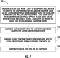
- the exemplary method 200 includes at 210 providing a casting core within a cavity of a component mold.
- the cavity of the component mold may define an outer component shape and the casting core may define an inner component shape.
- the casting core may comprise a core wall, the core wall defining a core outer surface and a core inner surface disposed opposite the core outer surface.
- the core inner surface may define a core cavity, and the casting core may include a removal facilitation feature.
- the exemplary method 200 includes at 212, casting the component within the cavity of the mold with the casting core positioned therein.
- the exemplary method 200 includes at 214, removing the component from the mold, with the casting core positioned internally within the component. Additionally, the exemplary method 200 includes at 216, removing the casting core from the cast component.
- the engine 100 may include a core gas turbine engine (indicated generally by reference character 114) and a fan section 116 positioned upstream thereof.
- the core engine 114 may generally include a substantially tubular outer casing 118 that defines an annular inlet 120.
- the outer casing 118 may further enclose and support a booster compressor 122 for increasing the pressure of the air that enters the core engine 114 to a first pressure level.
- a high pressure, multi-stage, axial-flow compressor 124 may then receive the pressurized air from the booster compressor 122 and further increase the pressure of such air.
- the pressurized air exiting the high-pressure compressor 124 may then flow to a combustor 126 within which fuel is injected by a fuel system 162 into the flow of pressurized air, with the resulting mixture being combusted within the combustor 126.
- the high energy combustion products are directed from the combustor 126 along the hot gas path of the engine 100 to a first (high pressure, HP) turbine 128 for driving the high pressure compressor 124 via a first (high pressure, HP) drive shaft 130, and then to a second (low pressure, LP) turbine 132 for driving the booster compressor 122 and fan section 116 via a second (low pressure, LP) drive shaft 134 that is generally coaxial with first drive shaft 130.
- the combustion products may be expelled from the core engine 114 via an exhaust nozzle 136 to provide propulsive jet thrust.
- each turbine 128, 132 may generally include one or more turbine stages, with each stage including a turbine nozzle and a downstream turbine rotor.
- the turbine nozzle may include a plurality of vanes disposed in an annular array about the centerline axis 112 of the engine 100 for turning or otherwise directing the flow of combustion products through the turbine stage towards a corresponding annular array of rotor blades forming part of the turbine rotor.
- the rotor blades may be coupled to a rotor disk of the turbine rotor, which is, in turn, rotationally coupled to the turbine's drive shaft (e.g., drive shaft 130 or 134).
- the fan section 116 of the engine 100 may generally include a rotatable, axial-flow fan rotor 138 surrounded by an annular fan casing 140.
- the (LP) drive shaft 134 may be connected directly to the fan rotor 138 such as in a direct-drive configuration.
- the (LP) drive shaft 134 may be connected to the fan rotor 138 via a speed reduction device 137 such as a reduction gear gearbox in an indirect-drive or geared-drive configuration.
- speed reduction devices may be included between any suitable shafts / spools within engine 100 as desired or required.
- the fan casing 140 may be supported relative to the core engine 114 by a plurality of substantially radially-extending, circumferentially-spaced outlet guide vanes 142. As such, the fan casing 140 may enclose the fan rotor 138 and its corresponding fan rotor blades 144. Moreover, a downstream section 146 of the fan casing 140 may extend over an outer portion of the core engine 114 to define a secondary, or by-pass, airflow conduit 148 that provides additional propulsive jet thrust.
- an initial air flow 150 may enter the engine 100 through an associated inlet 152 of the fan casing 140.
- the initial air flow 150 then passes through the fan blades 144 and splits into a first compressed air flow 154 (indicated by arrow) that moves through conduit 148 and a second compressed air flow 156 (indicated by arrow) that enters the booster compressor 122.
- the pressure of the second compressed air flow 156 is then increased and enters the high-pressure compressor 124 (as indicated by arrow 158).
- the combustion products 160 exit the combustor 126 and flow through the first turbine 128. Thereafter, the combustion products 160 flow through the second turbine 132 and exit the exhaust nozzle 136 to provide thrust for the engine 100.
Landscapes
- Engineering & Computer Science (AREA)
- Mechanical Engineering (AREA)
- Manufacturing & Machinery (AREA)
- Chemical & Material Sciences (AREA)
- Ceramic Engineering (AREA)
- Materials Engineering (AREA)
- Molds, Cores, And Manufacturing Methods Thereof (AREA)
Abstract
Description
- The present subject matter relates generally to the production of components for gas turbine engines, and more particularly, to a removable casting core and method of manufacturing.
- Gas turbine engine components, such as turbine airfoils, are frequently manufactured using an investment casting process in which molten metal alloy is introduced into a mold cavity defined between a shell and a core and allowed to solidify, forming a completed casting. A time-consuming step in the manufacturing process is removal of the core after the casting is complete.
- The removal of the core after casting often involves leaching out the core material with a caustic solution (usually aqueous sodium hydroxide or potassium hydroxide for ceramic cores). In the future, this challenge will be magnified as higher temperature, yttrium-containing alloys are used, requiring non-reactive casting core materials such as alumina- and zirconia-based ceramics. These core materials leach much more slowly than silica-based materials currently in use.
- Additionally, process improvements in other aspects of the production cycle have highlighted a production bottleneck resulting from current leaching techniques. The requirement to use multiple leaching cycles, often spread over days, slows down and disrupts the consistent part flow through the processing facility. Reducing this disruption will reduce work-in-progress inventories and facilitate faster, more consistent part flow.
- Accordingly, there remains a need for a casting core that is readily removable.
- Aspects and advantages of the invention will be set forth in part in the following description, or may be obvious from the description, or may be learned through practice of the invention.
- In one aspect, the present disclosure is directed to a method for casting a component. The method may include providing a casting core within a cavity of a component mold. The cavity of the component mold may define an outer component shape and the casting core may define an inner component shape. The casting core may include a core wall. The core wall may define a core outer surface and a core inner surface disposed opposite the core outer surface. The core inner surface may define a core cavity and the casting core may include a removal facilitation feature. The method may also include casting the component within the cavity of the component mold with the casting core positioned therein. Additionally, the method may include removing the cast component from the component mold, with the casting core positioned internally within the component. The method may further include removing the casting core from the cast component.
- These and other features, aspects and advantages of the present invention will become better understood with reference to the following description and appended claims. The accompanying drawings, which are incorporated in and constitute a part of this specification, illustrate embodiments of the invention and, together with the description, serve to explain the principles of the invention.
- A full and enabling disclosure of the present invention, including the best mode thereof, directed to one of ordinary skill in the art, is set forth in the specification, which makes reference to the appended figures, in which:
-
FIG. 1 illustrates a schematic cross-sectional view of one embodiment of a gas turbine engine for use in in accordance with the present disclosure; -
FIGS. 2A and2B illustrate schematic views of methods for forming a cast component in accordance with the present disclosure; -
FIG. 3A illustrates a schematic cross-sectional view of one embodiment of a method for forming a casting core for use in the exemplary method ofFIG. 2A ; -
FIG. 3B illustrates a schematic top view of one embodiment of a method for forming a casting core for use in the exemplary method ofFIG. 2A ; -
FIG. 4A illustrates a schematic cross-sectional view of one embodiment of a method for forming a casting core, which may have a sub-core, for use in the exemplary method ofFIG. 2A ; -
FIG. 4B illustrates a schematic cross-sectional view of one embodiment of a method for forming a casting core, which may have a sub-core, simultaneously with forming a component mold, for use in the exemplary method ofFIG. 2B ; -
FIG. 5A illustrates a schematic top view of one embodiment of a method for forming a casting core, which may have a support web, for use in the exemplary method ofFIG. 2A ; -
FIG. 5B illustrates a schematic top view of one embodiment of a method for forming a casting core, which may have a support web comprising a single structural member, for use in the exemplary method ofFIG. 2A ; -
FIG. 5C illustrates a schematic top view of one embodiment of a method for forming a casting core, which may have a support web, simultaneously with forming a component mold, for use in the exemplary method ofFIG. 2B ; -
FIG. 6 illustrates a schematic top view of one embodiment of a method for forming a casting core, which may have a support web comprising a foam, for use in the exemplary method ofFIG. 2 ; and -
FIG. 7 provides a flow diagram for casting a component as illustrated by the exemplary methods ofFIGS. 2A and2B . - Repeat use of reference characters in the present specification and drawings is intended to represent the same or analogous features or elements of the present invention.
- Reference now will be made in detail to embodiments of the invention, one or more examples of which are illustrated in the drawings. Each example is provided by way of explanation of the invention, not limitation of the invention. In fact, it will be apparent to those skilled in the art that various modifications and variations can be made in the present invention without departing from the scope of the invention. For instance, features illustrated or described as part of one embodiment can be used with another embodiment to yield a still further embodiment. Thus, it is intended that the present invention covers such modifications and variations as come within the scope of the appended claims and their equivalents.
- As used herein, the terms "first", "second", and "third" may be used interchangeably to distinguish one component from another and are not intended to signify location or importance of the individual components.
- The terms "upstream" and "downstream" refer to the relative direction with respect to fluid flow in a fluid pathway. For example, "upstream" refers to the direction from which the fluid flows, and "downstream" refers to the direction to which the fluid flows.
- In general, the present subject matter is directed to a method for forming a cast component. The method may include a number of processes each of which may also be a method. These processes may include the casting of the component and the formation of the casting core to be used in the component casting process. The casting core may be formed by various manufacturing methods including casting and additive manufacturing. The casting core may be formed with removal facilitation features, which enable the casting core to be more easily removed from the cast component. The removal facilitation features may include cavities, support webs, or easily-removable sub-cores. Generally, the removal facilitation features enable a leaching solution to contact a greater surface area of the casting core at one time then would be accessible using known techniques. With a greater surface area of the casting core being affected at once, the casting core may be more quickly removed from the cast component.
- Referring now to the drawings,
FIG. 1 illustrates a cross-sectional view of one embodiment of agas turbine engine 100 that may be utilized with an aircraft in accordance with aspects of the present subject matter. Various components of thegas turbine engine 100 may be formed via the methods for casting a component disclosed herein. Theengine 100 is shown having a longitudinal oraxial centerline axis 112 extending therethrough for reference purposes. Theengine 100 will be discussed in detail below. Although shown as a turbofan jet engine, the methods described herein may be used on any turbomachine including, but not limited to, high-bypass turbofan engines, low-bypass turbofan engines, turbojet engines, turboprop engines, turboshaft engines, propfan engines, and so forth. The turbomachine may be configured in any suitable manner, such as for vehicle propulsion or ground-based power production. -
FIGS. 2A-2B illustrate schematic views of amethod 200 for forming acast component 202. As depicted inFIGS. 2A-2B , themethod 200 for forming acast component 202 may include a plurality of processes, each of which, may also be a method. For example, themethod 200 may include a core-formation method component casting process 400. As will be more fully detailed below, themethod 200 may generally include the steps of forming acasting core 302 via the core-formation method casting core 302 within acavity 402 of acomponent mold 404. In accordance with thecomponent casting process 400, thecast component 202 may be cast within thecavity 402. Thecasting core 302 may then be removed from thecast component 202. In one embodiment, thecast component 202 is a turbine engine component of thegas turbine engine 100. It should be appreciated that the progression of steps, or processes, in themethod 200 for forming acast component 202 is represented inFIG. 2A by arrows A-D and inFIG. 2B by arrows A-C. As shown, themethod 200 may include two distinct molds, thecomponent mold 404 used in thecomponent casting process 400 and acore mold 304 used inmethod 300, and thecasting core 302 produced using thecore mold 304 may be positioned subsequently into thecomponent mold 404. In an alternative embodiment, themethod 200 may use only a single mold, thecomponent mold 404 in thecomponent casting process 400, and thecasting core 302 may be provided to thecomponent mold 404 by simultaneously forming thecasting core 302 andcomponent mold 404 via anadditive manufacturing device 303 by anadditive manufacturing method 301 inFIG. 2B . Additionally, two distinct cores may be used, thecasting core 302 and a sub-core 324 (FIGS. 4A-4B ), wherein the sub-core 324 may be separately formed and positioned in thecasting core 302 or may be simultaneously formed with thecasting core 302.
As depicted inFIG. 2A , the core-formation method 300 may include thecore mold 304. Thecore mold 304 may be formed with a core moldinner face 306, which is the negative of a casting coreouter shape 308. Thecasting core 302 may be a hollow core and may comprise acore wall 310 defining a coreouter surface 312 and a core inner surface (FIG. 3B , 314) disposed opposite the coreouter surface 312. The coreinner surface 314 may define a core cavity (FIG. 3B , 316). Thecasting core 302 may also include a removal facilitation feature (FIG. 3B , 318), as will be discussed in more detail below. It should be appreciated that the inclusion of thecore mold 304 inFIG. 2A is not intended to limit the core-formation method 300 to a particular manufacturing method, such as casting. Rather, thecasting core 302 may be formed by any suitable manufacturing method. For example, thecasting core 302 may be an additive manufacturing product, thereby eliminating Step A inFIG. 2A . Further, thecasting core 302 may be separately produced by additive manufacturing and positioned into thecomponent mold 404 as inFIG. 2B , or both thecasting core 302 andcomponent mold 404 may be an additive manufacturing product, produced simultaneously. - The
casting core 302 may be constructed from a refractory material capable of maintaining structural integrity when exposed to molten metal alloys at high temperatures. For example, the core may be formed from a solid ceramic material. Nonlimiting examples of ceramics include those based on silica, alumina, calcium, magnesium, zirconia, and other refractory oxides. Materials such as alumina- and zirconia-based ceramics are considered nonreactive with certain metal alloys. In one embodiment, thecasting core 302 may be constructed of a core material (Mc) that may be brittle between 1314°C and 21°C. - As previously stated, the
component casting process 400 may include acomponent mold 404 that may define acavity 402. Thecavity 402 may define anouter component shape 204 of thecast component 202. Thecasting core 302 may be provided within thecavity 402 of thecomponent mold 404 so that thecasting core 302 defines aninner component shape 206. With thecasting core 302 positioned within thecomponent mold 404, molten component material (CM) may be introduced into thecomponent mold 404 to form thecast component 202. Once the component material (CM) has cooled and solidified, thecast component 202, with thecasting core 302 positioned internally within thecast component 202, may be removed from thecomponent mold 404. In at least one embodiment, a caustic leaching solution (Ls) may be applied to thecasting core 302 to leach thecasting core 302 from within thecast component 202. It should be appreciated that in order to remove thecasting core 302 from within thecast component 202, the caustic leaching solution (Ls) must be brought into contact with thecasting core 302. As such, the amount of surface area of thecasting core 302 that may be affected by the leaching solution (Ls) at any given time may affect the rate at which the leaching process proceeds. Accordingly, in at least one embodiment, the removal facilitation feature 318 may be a feature of thecasting core 302 that increases the amount of surface area of thecasting core 302 that may be affected by the leaching solution (Ls) at any given time. - It should be appreciated that increasing the surface area of the
casting core 302 may increase the effectiveness of other core removal techniques. For example, in at least one embodiment, a water jet may be employed to remove thecasting core 302 from within thecast component 202. In such an embodiment, the greater the surface area of thecasting core 302 that may be subjected to the waterjet, the more effective the waterjet may be at removing thecasting core 302 from thecast component 202. In another exemplary embodiment, thecasting core 302 may be subjected to a vibration. In such an embodiment, an increase in surface area of thecasting core 302 may permit a greater vibrational movement of thecasting core 302, which may lead to the fracturing and removal of thecasting core 302. -
FIG. 3A illustrates a schematic cross-sectional view of an embodiment of a method for forming a casting core for use in theexemplary method 200. As depicted inFIG. 3A , the core-formation method 300 may include aninjection apparatus 320. Theinjection apparatus 320 may be inserted into thecore mold 304. With further reference toFIGS. 3B , in an embodiment, theinjection apparatus 320 may deposit one ormore layers 322 of core material (Mc) on the core moldinner face 306 to form thecore wall 310. In at least one embodiment, theinjection apparatus 320 may deposit sufficient core material (Mc) to establish a core wall thickness (T) of 0.1 mm to 5 mm. Thecasting core 302 may have acore wall 310 comprising asingle core layer 322 having the core wall thickness (T) of 0.1 mm to 5 mm. In an alternative embodiment, as shown inFIG. 3B , thecore wall 310 may comprise a plurality of core layers 322 to establish the core wall thickness (T) of 0.1 mm to 5 mm. By way of further example, the core wall thickness (T) may be 0.1 mm to 4 mm, 0.5 mm to 4 mm, 0.5 mm to 2.5 mm, 0.1 mm to 2.5 mm, 1 mm to 3 mm, or 2 mm to 4 mm. It should be appreciated that, in at least one embodiment, the thickness (T) may be the removal facilitation feature 318. As such, the thickness (T) may be selected to ensure thecasting core 302 is of sufficient strength to resist compression as thecast component 202 is cast, while minimizing the amount of core material (Mc) to be removed and maximizing the amount of surface area of thecasting core 302 that may be affected by the leaching solution (Ls) at any given time. - With specific reference to the embodiment of
FIG. 3B , thecore wall 310 may comprise a plurality of core layers 322. Theinjection apparatus 320 may deposit successive core layers 322 until the core wall thickness (T), e.g., 0.1 mm to 5 mm, is achieved. In an exemplary embodiment wherein theinjection apparatus 320 deposits successive core layers 322, theinjection apparatus 320 may be inserted into thecore mold 304 and may deposit acore layer 322 as theinjection apparatus 320 is withdrawn from thecore mold 304. Theinjection apparatus 320 may then be reinserted into thecore mold 304 and may deposit anadditional core layer 322 as theinjection apparatus 320 is again withdrawn from thecore mold 304. The process of inserting theinjection apparatus 320 and depositing acore layer 322 may be repeated until the core wall thickness (T), e.g., 0.1 mm to 5 mm, is achieved. - In the various embodiments in accordance with the present disclosure, the removal facilitation feature 318 may include structures and materials that may serve to make the
casting core 302 more susceptible to known removal processes. For example, thecore wall 310 may have sufficient strength to resist deformation during thecomponent casting process 400 and, thus, thecore cavity 316 may be formed without the inclusion of any additional support elements. In such an embodiment, the entirety of the surface area of the coreinner surface 314 may be simultaneously exposed to known leaching processes. In additional embodiments, thecasting core 302 may include, within thecore cavity 316, additional support structures as may be necessary to reduce, or eliminate, deformation of thecasting core 302 during the casting process. In such embodiments, the removal facilitation features 318 may include filling thecore cavity 316 with a highly-removable sub-core or a support web to provide structural support while maintaining a maximal surface area that may be instantly exposed to a removal process, such as leaching. -
FIG. 4A illustrates a schematic cross-sectional view of one embodiment of a method for forming a casting core, which may have a sub-core, for use in theexemplary method 200. As depicted inFIG. 4A , the core-formation method 300 may include a sub-core 324 comprising asub-core material 326. Thecore mold 304 may be formed with a core moldinner face 306 that is the negative of a casting coreouter shape 308. The sub-core 324 may be secured within thecore mold 304 and a portion of core material (Mc) may be introduced into thecore mold 304 to form thecore wall 310 as asingle core layer 322. Once the core material (Mc) has cooled and solidified, thecasting core 302 may be removed from thecore mold 304. The sub-core 324 may be removed from thecasting core 302 to expose thecore cavity 316. - The
sub-core material 326, in an alternative embodiment, may comprise an easily removable material yet possess sufficient rigidity to provide structural support to thecasting core 302. As such, the sub-core 324 may be easily removable, and may be the removal facilitation feature 318 within thecore cavity 316. In such an embodiment, the sub-core 324 may be maintained in thecasting core 302 until thecast component 202 is cast. Once thecast component 202 is cast, the sub-core 324 may be exposed to rapid leaching and removed from thecasting core 302. The rapid leaching of the sub-core 324 may expose a greater surface area of thecasting core 302 to the leaching process. - In another embodiment as depicted in
FIG. 4A , thecasting core 302 may be formed by any of the methods described herein, wherein thecasting core 302 is formed with thecore cavity 316. The sub-core 324, comprising thesub-core material 326, may be formed separately and inserted into thecore cavity 316. In such an embodiment, thecasting core 302 may have a core wall thickness (T) of 0.1 mm to 5 mm and may be structurally supported by the spanning of thecore cavity 316 by the sub-core 324. Because thesub-core material 326 may be an easily removable material, the sub-core 324 may be the removal facilitation feature 318 within thecore cavity 316. - In yet another embodiment as depicted in
FIG. 4B , multi-material additive manufacturing may be used to form thecasting core 302, sub-core 324, andcomponent mold 404 simultaneously. Thecasting core 302 with the sub-core 324 therein may thus be provided to thecomponent mold 404 simultaneously with formation of thecomponent mold 404. Thecavity 402 may include one or more features (not shown) connecting thecasting core 302 to the component mold, which may serve as support structures during casting, and which may leach out to form features, such as holes and passages, in thecast component 202. Alternatively, the sub-core 324 may be formed separately and thereafter inserted into the additively manufacturedcasting core 302 andcomponent mold 404 to provide support during the subsequentcomponent casting process 400. -
FIGs. 5A, 5B ,5C , and6 illustrate schematic top views of embodiments of a method for forming a casting core, which may have a support web, for use in theexemplary method 200. As depicted inFIGS. 5A-5C , thecore formation methods core cavity 316 and coupled to the coreinner surface 314. The support web 328 may be a removal facilitation feature 318 within thecore cavity 316. The support web 328 may comprise a plurality of pores, cavities, or voids 330. The plurality of pores, cavities, or voids 330 may facilitate penetration of a caustic leaching solution (Ls) during core removal. In other words, because the support web 328 permits the penetration of the caustic leaching solution (Ls), maximal surface area of the coreinner surface 314 may be exposed to the leaching process at once. Additionally, the plurality of pores, cavities, or voids 330 may increase the effectiveness of other core removal methods, such as a water jet or vibration. - In addition to facilitating transportation of the leaching solution (Ls) into and out of the
core cavity 316, the support web 328 may be configured to provide structural support for thecore 302. The support web 328 may ensure mechanical support is provided in areas subject to high stress during thecomponent casting process 400. The support web 328 may also limit or control thermal expansion of the core 302 during the casting process. The support web 328 may take any suitable form including a plurality ofsupport members 332, a single structural member 334, or a foam (FIG. 6 , 336). It should be appreciated that the web 328 may be formed from the core material (Mc), thesub-core material 326, or other suitable material. - In an embodiment such as depicted in
FIGS. 5A and5C , the support web 328 may comprise a plurality ofsupport members 332. The plurality ofsupport members 332 may span thecore cavity 316 and be coupled to the coreinner surface 314. At least two support members of the plurality ofsupport members 332 may meet at anintersection 338. In one embodiment, the plurality ofsupport members 332 may be arranged in a repeating pattern to form a lattice structure having a plurality ofintersections 338. The plurality ofsupport members 332 may intersect the coreinner surface 314 at specific locations where a high stress load is computed. For example, the location having a high stress load may be a gradient peak having a stress concentration value which is greater than the stress concentration of at least one adjacent region. In such an embodiment, the arrangement of the plurality ofsupport members 332 may have no discernible pattern and may not include theintersection 338. In one embodiment, the plurality ofsupport members 332 may comprise a plurality of beams. In another embodiment, the plurality ofsupport members 332 may comprise a plurality of dividers or walls extending. Each divider or wall may be a unitary structure extending substantially along the core inner surface. For example, in at least one embodiment, each divider wall may have an edge length substantially equal to a depth of thecore cavity 316. In yet another embodiment, the plurality ofsupport members 332 may comprise at least one beam and at least one divider or wall, wherein the at least one beam has a maximal length greater than a maximal thickness. It should be appreciated that, in an exemplary embodiment, the plurality ofsupport members 332 may form a lattice structure, such as a honeycomb, on the coreinner surface 314. The lattice structure may conform to the shape of the coreinner surface 314 and may not span thecore cavity 316. -
FIG. 5B depicts an embodiment wherein the support web 328 may comprise a single structural member 334. The single structural member 334 may have afirst support end 340 coupled to a first innersurface attachment location 342 and asecond support end 344 coupled to a second innersurface attachment location 346. The first innersurface attachment location 342 and the second innersurface attachment location 346 may be located along the coreinner surface 314 at locations selected to orient the single structural member 334 to ensure mechanical support is provided in areas subject to high stress during thecomponent casting process 400. It should be appreciated that in one embodiment, the single structural member may be a beam, and in an additional embodiment, the single structural member may be a divider or wall. - In an embodiment in accordance with
FIGs. 5A and 5B , thecore formation method 300 may include forming thecasting core 302 by a casting process. In one embodiment wherein thecasting core 302 is formed by casting, the sub-core 324 may be formed to integrate the support web 328. In such an embodiment, the sub-core 324, integrating the support web 328, may remain in thecasting core 302 following the removal of thecasting core 302 from thecore mold 304. Thecasting core 302, containing the integrated support web 328, may then be employed in thecomponent casting process 400 as previously discussed. In an alternative embodiment, the sub-core 324 may be formed to integrate the support web 328 into the coreinner surface 314. Following the casting of the casting core, the sub-core 324 may be removed from thecasting core 302 leaving thecasting core 302 and the support web 328 as a unitary structure. - The support web 328 may, in an exemplary embodiment, be an additive manufacturing product. The sub-core 324 integrating the support web 328 may be produced through additive manufacturing processes. The sub-core 324 may then be employed in the
core formation process 300 to form thecasting core 302. In an additional embodiment, the support web 328 may be incorporated into thecasting core 302 as a unitary structure. Thecasting core 302 and the integrated support web 328 may be produced via additive manufacturing processes. As shown inFIG. 5C , thecomponent mold 404 also may be simultaneously formed via the additive manufacturing process, or it may be formed separately and the additively manufacturedcasting core 302 with integrated support web 328 may thereafter be positioned in thecavity 402. It should be appreciated that the support web 328 may, alternatively, be additively manufactured and inserted into thecore cavity 316 of the core 302 produced by any of the processes discussed above. -
FIG. 6 depicts an embodiment wherein the support web 328, and thus the removal facilitation feature 318, comprises a foam 336. The foam 336 may be any suitable material. For example, the foam may be a ceramic foam, a metallic foam, or an expanding foam. In one embodiment, the foam 336 may be thesub-core material 326 and the foam 336 may be the sub-core 324. The foam 336, when employed as the sub-core 324, may be used in thecore formation process 300 when casting thecasting core 302. In an alternative embodiment, thecasting core 302 may be formed with thecore cavity 316 by any of the processes described herein. The foam 336 may be inserted into thecore cavity 316 to provide structural support to thecasting core 302 while still permitting the leaching solution (LS) to penetrate into thecore cavity 316 during the leaching process. Similarly, in one embodiment, thecore cavity 316 may be formed as discussed above. The foam 336 may be an expanding foam that may be introduced into thecavity 316 and permitted to expand and fill thecavity 316. The expanding foam may also comprise a material that is highly removable. The expanding foam may be formulated with a ceramic and have a self-skinning feature wherein the foam 336 may expand to fill thecavity 316 and form a skin at the surface. The support web 328, when comprising the foam 336, may be the removal facilitation feature 318. - As used herein, the terms "additively manufactured" or "additive manufacturing techniques or processes" refer generally to manufacturing processes wherein successive layers of material(s) are provided on each other to "build-up," layer-by-layer, a three-dimensional component. The successive layers generally fuse together to form a monolithic component that may have a variety of integral sub-components. Although additive manufacturing technology is described herein for the fabrication of complex objects by building objects point-by-point, layer-by-layer, typically in a vertical direction, other methods of fabrication are possible and within the scope of the present subject matter. For example, although the discussion herein refers to the addition of material to form successive layers, one skilled in the art will appreciate that the methods and structures disclosed herein may be practiced with any additive manufacturing technique or manufacturing technology. For example, embodiments of the present invention may use layer-additive processes, layer-subtractive processes, or hybrid processes.
- Suitable additive manufacturing techniques in accordance with the present disclosure include, for example, Fused Deposition Modeling (FDM), Selective Laser Sintering (SLS), 3D printing such as by inkjets, laser jets, and binder jets, Sterolithography (SLA), Direct Selective Laser Sintering (DSLS), Electron Beam Sintering (EBS), Electron Beam Melting (EBM), Laser Engineered Net Shaping (LENS), Laser Net Shape Manufacturing (LNSM), Direct Metal Deposition (DMD), Digital Light Processing (DLP), Direct Selective Laser Melting (DSLM), Selective Laser Melting (SLM), Direct Metal Laser Melting (DMLM), and other known processes.
- The additive manufacturing processes described herein may be used for forming components using any suitable material. For example, the material may be plastic, metal, concrete, ceramic, polymer, epoxy, photopolymer resin, wax, or any other suitable material. These materials are examples of materials suitable for use in the additive manufacturing processes described herein and may be generally referred to as "additive materials."
- In addition, one skilled in the art will appreciate that a variety of materials and methods for bonding those materials may be used and are contemplated as within the scope of the present disclosure. As used herein, references to "fusing" may refer to any suitable process for creating a bonded layer of any of the above materials. For example, if an object is made from polymer, fusing may refer to creating a thermoset bond between polymer materials. If the object is epoxy, the bond may be formed by a crosslinking process. If the material is ceramic, the bond may be formed by a sintering process. If the material is powdered metal, the bond may be formed by a melting or sintering process. One skilled in the art will appreciate that other methods of fusing materials to make a component by additive manufacturing are possible, and the presently disclosed subject matter may be practiced with those methods.
- In addition, the additive manufacturing process disclosed herein allows a single component to be formed from multiple materials. Thus, the components described herein may be formed from any suitable mixtures of the above materials. For example, a component may include multiple layers, segments, or parts that are formed using different materials, processes, and/or on different additive manufacturing machines. In this manner, components may be constructed that have different materials and material properties for meeting the demands of any application. In addition, the components described herein may be constructed entirely by additive manufacturing processes, or all or a portion of these components may be formed via casting, machining, and/or any other suitable manufacturing process. Indeed, any suitable combination of materials and manufacturing methods may be used to form these components.
- An exemplary additive manufacturing process will now be described. Additive manufacturing processes fabricate components using three-dimensional (3D) information, for example a three-dimensional computer model, of the component. Accordingly, a three-dimensional design model of the component may be defined prior to manufacturing. In this regard, a model or prototype of the component may be scanned to determine the three-dimensional information of the component. As another example, a model of the component may be constructed using a suitable computer aided design (CAD) program to define the three-dimensional design model of the component as depicted in
FIGs. 2A-6 . - The design model may include 3D numeric coordinates of the entire configuration of the component including both external and internal surfaces of the component. For example, the design model may define the body, the surface, and/or internal passageways such as openings, support structures, etc. In one exemplary embodiment, the three-dimensional design model is converted into a plurality of slices or segments, e.g., along a central (e.g., vertical) axis of the component or any other suitable axis. Each slice may define a thin cross section of the component for a predetermined height of the slice. The plurality of successive cross-sectional slices together form the 3D component. The component is then "built-up" slice-by-slice, or layer-by-layer, until finished.
- In this manner, the components described herein may be fabricated using the additive process, or more specifically each layer is successively formed, e.g., by fusing or polymerizing a plastic using laser energy or heat or by sintering or melting metal powder. For example, a particular type of additive manufacturing process may use an energy beam, for example, an electron beam or electromagnetic radiation such as a laser beam, to sinter or melt a powder material or polymerize a liquid. Any suitable laser and laser parameters may be used, including considerations with respect to power, laser beam spot size, and scanning velocity. The build material may be formed by any suitable powder or material selected for enhanced strength, durability, and useful life, particularly at high temperatures.
- Each successive layer may be, for example, between about 10 µm and 200 µm, although the thickness may be selected based on any number of parameters and may be any suitable size according to alternative embodiments. Therefore, utilizing the additive formation methods described above, the components described herein may have cross sections as thin as one thickness of an associated powder layer, e.g., 10 µm, utilized during the additive formation process.
- In addition, utilizing an additive process, the surface finish and features of the components may vary as needed depending on the application. For example, the surface finish may be adjusted (e.g., made smoother or rougher) by selecting appropriate laser scan parameters (e.g., laser power, scan speed, laser focal spot size, etc.) during the additive process, especially in the periphery of a cross-sectional layer that corresponds to the part surface. For example, a rougher finish may be achieved by increasing laser scan speed or decreasing the size of the melt pool formed, and a smoother finish may be achieved by decreasing laser scan speed or increasing the size of the melt pool formed. The scanning pattern and/or laser power can also be changed to change the surface finish in a selected area.
- Notably, in exemplary embodiments, several features of the components described herein were previously not possible due to manufacturing restraints. However, the present inventors have advantageously utilized current advances in additive manufacturing techniques to develop exemplary embodiments of such components generally in accordance with the present disclosure. While the present disclosure is not limited to the use of additive manufacturing to form these components generally, additive manufacturing does provide a variety of manufacturing advantages, including ease of manufacturing, reduced cost, greater accuracy, etc.
- In this regard, utilizing additive manufacturing methods, even multi-part components may be formed as a single piece of additive ceramic or additive plastic, and may thus include fewer sub-components and/or joints compared to prior designs. The integral formation of these multi-part components through additive manufacturing may advantageously improve the overall assembly process. For example, the integral formation reduces the number of separate parts that must be assembled, thus reducing associated time and overall assembly costs. Additionally, existing issues with, for example, leakage, joint quality between separate parts, and overall performance may advantageously be reduced.
- Also, the additive manufacturing methods described above enable much more complex and intricate shapes and contours of the components described herein. In addition, the additive manufacturing process enables the manufacture of a single component having different materials such that different portions of the component may exhibit different performance characteristics. The successive, additive nature of the manufacturing process enables the construction of these novel features. As a result, the components described herein may enable more intricate internal cast component shapes.
- Referring now to
FIG. 7 , a flow diagram of amethod 200 for casting a component is presented. Theexemplary method 200 includes at 210 providing a casting core within a cavity of a component mold. The cavity of the component mold may define an outer component shape and the casting core may define an inner component shape. The casting core may comprise a core wall, the core wall defining a core outer surface and a core inner surface disposed opposite the core outer surface. The core inner surface may define a core cavity, and the casting core may include a removal facilitation feature. Theexemplary method 200 includes at 212, casting the component within the cavity of the mold with the casting core positioned therein. Theexemplary method 200 includes at 214, removing the component from the mold, with the casting core positioned internally within the component. Additionally, theexemplary method 200 includes at 216, removing the casting core from the cast component. - Referring again to
FIG. 1 , in general, theengine 100 may include a core gas turbine engine (indicated generally by reference character 114) and afan section 116 positioned upstream thereof. Thecore engine 114 may generally include a substantially tubularouter casing 118 that defines anannular inlet 120. In addition, theouter casing 118 may further enclose and support abooster compressor 122 for increasing the pressure of the air that enters thecore engine 114 to a first pressure level. A high pressure, multi-stage, axial-flow compressor 124 may then receive the pressurized air from thebooster compressor 122 and further increase the pressure of such air. The pressurized air exiting the high-pressure compressor 124 may then flow to acombustor 126 within which fuel is injected by a fuel system 162 into the flow of pressurized air, with the resulting mixture being combusted within thecombustor 126. The high energy combustion products are directed from thecombustor 126 along the hot gas path of theengine 100 to a first (high pressure, HP)turbine 128 for driving thehigh pressure compressor 124 via a first (high pressure, HP)drive shaft 130, and then to a second (low pressure, LP)turbine 132 for driving thebooster compressor 122 andfan section 116 via a second (low pressure, LP) driveshaft 134 that is generally coaxial withfirst drive shaft 130. After driving each ofturbines core engine 114 via anexhaust nozzle 136 to provide propulsive jet thrust. - It should be appreciated that each
turbine centerline axis 112 of theengine 100 for turning or otherwise directing the flow of combustion products through the turbine stage towards a corresponding annular array of rotor blades forming part of the turbine rotor. As is generally understood, the rotor blades may be coupled to a rotor disk of the turbine rotor, which is, in turn, rotationally coupled to the turbine's drive shaft (e.g.,drive shaft 130 or 134). - Additionally, as shown in
FIG. 1 , thefan section 116 of theengine 100 may generally include a rotatable, axial-flow fan rotor 138 surrounded by anannular fan casing 140. In particular embodiments, the (LP) driveshaft 134 may be connected directly to thefan rotor 138 such as in a direct-drive configuration. In alternative configurations, the (LP) driveshaft 134 may be connected to thefan rotor 138 via aspeed reduction device 137 such as a reduction gear gearbox in an indirect-drive or geared-drive configuration. Such speed reduction devices may be included between any suitable shafts / spools withinengine 100 as desired or required. - It should be appreciated by those of ordinary skill in the art that the
fan casing 140 may be supported relative to thecore engine 114 by a plurality of substantially radially-extending, circumferentially-spaced outlet guide vanes 142. As such, thefan casing 140 may enclose thefan rotor 138 and its correspondingfan rotor blades 144. Moreover, adownstream section 146 of thefan casing 140 may extend over an outer portion of thecore engine 114 to define a secondary, or by-pass,airflow conduit 148 that provides additional propulsive jet thrust. - During operation of the
engine 100, it should be appreciated that an initial air flow 150 (indicated by arrow) may enter theengine 100 through an associatedinlet 152 of thefan casing 140. Theinitial air flow 150 then passes through thefan blades 144 and splits into a first compressed air flow 154 (indicated by arrow) that moves throughconduit 148 and a second compressed air flow 156 (indicated by arrow) that enters thebooster compressor 122. The pressure of the secondcompressed air flow 156 is then increased and enters the high-pressure compressor 124 (as indicated by arrow 158). After mixing with fuel and being combusted within thecombustor 126, the combustion products 160 exit thecombustor 126 and flow through thefirst turbine 128. Thereafter, the combustion products 160 flow through thesecond turbine 132 and exit theexhaust nozzle 136 to provide thrust for theengine 100. - This written description uses examples to disclose the invention, including the best mode, and also to enable any person skilled in the art to practice the invention, including making and using any devices or systems and performing any incorporated methods. The patentable scope of the invention is defined by the claims, and may include other examples that occur to those skilled in the art. Such other examples are intended to be within the scope of the claims if they include structural elements that do not differ from the literal language of the claims, or if they include equivalent structural elements with insubstantial differences from the literal languages of the claims.
- Further aspects of the invention are provided by the subject matter of the following clauses:
-
Clause 1. A method for casting a component, the method comprising: providing a casting core within a cavity of a component mold, wherein the cavity of the component mold defines an outer component shape and the casting core defines an inner component shape, the casting core comprising a core wall, the core wall defining a core outer surface and a core inner surface disposed opposite the core outer surface, wherein the core inner surface defines a core cavity, and wherein the casting core includes a removal facilitation feature; casting the cast component within the cavity of the component mold with the casting core positioned therein; removing the cast component from the component mold, with the casting core positioned internally within the component; and removing the casting core from the cast component. - Clause 2. The method of any preceding clause, wherein the core wall comprises a plurality of core layers.
- Clause 3. The method of any preceding clause, wherein the casting core is formed by a core-formation method comprising: inserting an injection apparatus into a core mold, wherein the core mold is formed with a core mold inner face being the negative of a casting core outer shape; low depositing a layer of a core material on the core mold inner face; forming the removal facilitation feature by depositing additional layers of the core material until a core wall thickness of 0.1 mm to 5 mm is established; and removing the casting core from the core mold.
- Clause 4. The method of any preceding clause, wherein the removal facilitation feature comprises the core wall having a core wall thickness of 0.1 mm to 5 mm.
- Clause 5. The method of any preceding clause, wherein the casting core is formed by an additive manufacturing process.
- Clause 6. The method of any preceding clause, wherein the component mold is formed by the additive manufacturing process simultaneously with forming the casting core.
- Clause 7. The method of any preceding clause, wherein the casting core is formed by a core-formation method comprising: forming a sub-core comprising a sub-core material; securing the sub-core within a core mold, wherein the core mold is formed with a core mold inner face being the negative of a core outer shape; introducing a core material into the core mold to form the core wall; removing the casting core from the core mold; and leaching the sub-core from the casting core.
- Clause 8. The method of any preceding clause, wherein the removal facilitation feature comprises: a support web contained within the core cavity and coupled to the core inner surface.
- Clause 9. The method of any preceding clause, wherein the support web is a single structural member with a first support end coupled to a first inner surface attachment location and a second support end coupled to a second inner surface attachment location.
- Clause 10. The method of any preceding clause, wherein the support web comprises: a plurality of support members each having a first support end coupled to a first inner surface attachment location and a second support end coupled to a second inner surface attachment location.
- Clause 11. The method of any preceding clause, wherein the support web is a ceramic foam or a metallic foam.
- Clause 12. The method of any preceding clause, wherein the casting core is formed by a core-formation method comprising: forming a sub-core comprising the support web; securing the sub-core within a core mold having a core mold inner face that is the negative of a core outer shape; introducing a core material into the core mold to form the core outer shape; and removing the casting core from the core mold.
- Clause 13. The method of any preceding clause, wherein the casting core and the support web are formed simultaneously by an additive manufacturing process.
- Clause 14. The method of any preceding clause, wherein the support web comprises: a plurality of support members each having a first support end coupled to a first inner surface attachment location and a second support end coupled to a second inner surface attachment location, the plurality of support members forming a lattice structure spanning the core cavity.
- Clause 15. The method of any preceding clause, further comprising: forming the core wall, the core outer surface, and the core inner surface; and introducing an expanding foam into the core cavity.
- Clause 16. The method of any preceding clause, wherein the cast component is a turbine engine component.
- Clause 17. The method of any preceding clause, wherein the removal facilitation feature comprises: a first core material having a thickness of 0.1 mm to 5 mm; and a second core material contained within the core cavity, wherein the second core material leaches at a faster rate than the first core material.
- Clause 18. The method of any preceding clause, further comprising: forming a sub-core comprising the second core material; securing the sub-core within a core mold having a core mold inner face that is the negative of a core outer shape; introducing the first core material into the core mold to form the core outer shape; and removing the casting core from the core mold.
- Clause 19. The method of any preceding clause, further comprising: inserting an injection apparatus into a core mold having a core mold inner face that is the negative of a casting core outer shape; depositing a layer of the first core material on the core mold inner face; depositing additional layers of the first core material until a core wall having a thickness of 0.1 mm to 5 mm is established; introducing the second core material into the cavity; and removing the casting core from the core mold.
- Clause 20. The method of any preceding clause, wherein the casting core is formed by an additive manufacturing process.
Claims (15)
- A method (200) for casting a component, the method (200) comprising:providing a casting core (302) within a cavity (316) of a component mold (404), wherein the cavity (316) of the component mold (404) defines an outer component shape (204) and the casting core (302) defines an inner component shape (206), the casting core (302) comprising a core wall (310), the core wall (310) defining a core outer surface (312) and a core inner surface (314) disposed opposite the core outer surface (312), wherein the core inner surface (314) defines a core cavity (316), and wherein the casting core (302) includes a removal facilitation feature (318);casting the cast component (202) within the cavity (316) of the component mold (404) with the casting core (302) positioned therein;removing the cast component (202) from the component mold (404), with the casting core (302) positioned internally within the component; andremoving the casting core (302) from the cast component (202).
- The method (200) of any preceding claim, wherein the core wall (310) comprises a plurality of core layers (322).
- The method (200) of any preceding claim, wherein the casting core (302) is formed by a core-formation method (300) comprising:inserting an injection apparatus (320) into a core mold (304), wherein the core mold (304) is formed with a core mold inner face (306) being the negative of a casting core outer shape (308);depositing a layer of a core (302) material on the core mold inner face (306);forming the removal facilitation feature (318) by depositing additional layers (322) of the core (302) material until a core wall (310) thickness of 0.1 mm to 5 mm is established; andremoving the casting core (302) from the core mold (304).
- The method (200) of any preceding claim, wherein the removal facilitation feature (318) comprises the core wall (310) having a core wall (310) thickness of 0.1 mm to 5 mm.
- The method (200) of any preceding claim, wherein the casting core (302) is formed by an additive manufacturing process.
- The method (200) of any preceding claim, wherein the component mold (404) is formed by an additive manufacturing process simultaneously with forming the casting core (302).
- The method (200) of any preceding claim, wherein the casting core (302) is formed by a core-formation method (300) comprising:forming a sub-core (324) comprising a sub-core material (326);securing the sub-core (324) within a core mold (304), wherein the core mold (304) is formed with a core mold inner face (306) being the negative of a core (302) outer shape;introducing a core (302) material into the core mold (304) to form the core wall (310);removing the casting core (302) from the core mold (304); andleaching the sub-core (324) from the casting core (302).
- The method (200) of any preceding claim, wherein the removal facilitation feature (318) comprises:
a support web (328) contained within the core cavity (316) and coupled to the core inner surface (314). - The method (200) of any preceding claim, wherein the support web (328) is a single structural member (334) with a first support end (340) coupled to a first inner surface attachment location (342) and a second support end (344) coupled to a second inner surface attachment location (346).
- The method (200) of any preceding claim, wherein the support web (328) comprises:
a plurality of support members (332) each having a first support end (340) coupled to a first inner surface attachment location (342) and a second support end (344) coupled to a second inner surface attachment location (346). - The method (200) of any preceding claim, wherein the support web (328) is a ceramic foam (336) or a metallic foam (336).
- The method (200) of any preceding claim, wherein the casting core (302) is formed by a core-formation method (300) comprising:forming a sub-core (324) comprising the support web (328);securing the sub-core (324) within a core mold (304) having a core mold inner face (306) that is the negative of a core (302) outer shape;introducing a core (302) material into the core mold (304) to form the core (302) outer shape; andremoving the casting core (302) from the core mold (304).
- The method (200) of any preceding claim, wherein the casting core (302) and the support web (328) are formed simultaneously by an additive manufacturing process.
- The method (200) of any preceding claim, wherein the support web (328) comprises:
a plurality of support members (332) each having a first support end (340) coupled to a first inner surface attachment location (342) and a second support end (344) coupled to a second inner surface attachment location (346), the plurality of support members (332) forming a lattice structure spanning the core cavity (316). - The method (200) of any preceding claim, further comprising:forming the core wall (310), the core outer surface (312), and the core inner surface (314); andintroducing an expanding foam (336) into the core cavity (316).
Applications Claiming Priority (1)
| Application Number | Priority Date | Filing Date | Title |
|---|---|---|---|
| US17/019,646 US11813665B2 (en) | 2020-09-14 | 2020-09-14 | Methods for casting a component having a readily removable casting core |
Publications (2)
| Publication Number | Publication Date |
|---|---|
| EP3967421A1 true EP3967421A1 (en) | 2022-03-16 |
| EP3967421B1 EP3967421B1 (en) | 2024-03-20 |
Family
ID=77519000
Family Applications (1)
| Application Number | Title | Priority Date | Filing Date |
|---|---|---|---|
| EP21193243.9A Active EP3967421B1 (en) | 2020-09-14 | 2021-08-26 | Methods for casting a component having a readily removable casting core |
Country Status (3)
| Country | Link |
|---|---|
| US (2) | US11813665B2 (en) |
| EP (1) | EP3967421B1 (en) |
| CN (1) | CN114178510B (en) |
Families Citing this family (1)
| Publication number | Priority date | Publication date | Assignee | Title |
|---|---|---|---|---|
| US12172206B1 (en) * | 2023-09-18 | 2024-12-24 | Rtx Corporation | Additive manufacturing fugitive multi-system material for ceramic core manufacture |
Citations (5)
| Publication number | Priority date | Publication date | Assignee | Title |
|---|---|---|---|---|
| US20030062145A1 (en) * | 1998-11-20 | 2003-04-03 | Frasier Donald J. | Method and apparatus for production of a cast component |
| US20170173671A1 (en) * | 2015-12-21 | 2017-06-22 | United Technologies Corporation | Additively Manufactured Core for Use in Casting An Internal Cooling Circuit of a Gas Turbine Engine Component |
| EP3187278A1 (en) * | 2015-12-17 | 2017-07-05 | General Electric Company | Method and assembly for forming components having a catalyzed internal passage defined therein |
| EP3210691A1 (en) * | 2016-02-29 | 2017-08-30 | General Electric Company | Casting with first metal components and second metal components |
| US20200157947A1 (en) * | 2018-11-19 | 2020-05-21 | General Electric Company | Reduced Cross Flow Linking Cavities and Method of Casting |
Family Cites Families (28)
| Publication number | Priority date | Publication date | Assignee | Title |
|---|---|---|---|---|
| US4093017A (en) | 1975-12-29 | 1978-06-06 | Sherwood Refractories, Inc. | Cores for investment casting process |
| GB2199822B (en) | 1987-01-17 | 1990-10-10 | Rolls Royce Plc | Ceramic core material and method of enhancing its leaching rate. |
| FR2666528B1 (en) * | 1990-09-12 | 1993-07-02 | Snecma | PROCESS FOR THE PREPARATION OF A FOUNDRY MOLD FROM FOAM AND CERAMIC BARBOTINES USED. |
| US5273104A (en) | 1991-09-20 | 1993-12-28 | United Technologies Corporation | Process for making cores used in investment casting |
| US5468285A (en) | 1994-01-18 | 1995-11-21 | Kennerknecht; Steven | Ceramic core for investment casting and method for preparation of the same |
| US5798066A (en) * | 1995-07-12 | 1998-08-25 | Certech Incorporated | Method of forming hollow ceramic articles |
| US5779809A (en) | 1995-12-26 | 1998-07-14 | General Electric Company | Method of dissolving or leaching ceramic cores in airfoils |
| US6637500B2 (en) * | 2001-10-24 | 2003-10-28 | United Technologies Corporation | Cores for use in precision investment casting |
| US20050006047A1 (en) * | 2003-07-10 | 2005-01-13 | General Electric Company | Investment casting method and cores and dies used therein |
| US20050087319A1 (en) * | 2003-10-16 | 2005-04-28 | Beals James T. | Refractory metal core wall thickness control |
| US7108045B2 (en) * | 2004-09-09 | 2006-09-19 | United Technologies Corporation | Composite core for use in precision investment casting |
| US20070221359A1 (en) * | 2006-03-21 | 2007-09-27 | United Technologies Corporation | Methods and materials for attaching casting cores |
| US8828214B2 (en) | 2010-12-30 | 2014-09-09 | Rolls-Royce Corporation | System, method, and apparatus for leaching cast components |
| US8393381B2 (en) | 2011-05-18 | 2013-03-12 | Pcc Airfoils, Inc. | Method of forming a cast metal article |
| US20160175923A1 (en) * | 2012-04-09 | 2016-06-23 | General Electric Company | Composite core for casting processes, and processes of making and using the same |
| FR2989293B1 (en) * | 2012-04-16 | 2023-06-09 | C T I F Centre Technique Des Ind De La Fonderie | METHOD FOR MANUFACTURING A HOLLOW METALLIC PART BY FOUNDRY |
| WO2015009448A1 (en) * | 2013-07-19 | 2015-01-22 | United Technologies Corporation | Additively manufactured core |
| DE102013016868A1 (en) * | 2013-10-11 | 2015-04-16 | Flc Flowcastings Gmbh | Investment casting of hollow components |
| CA2885074A1 (en) * | 2014-04-24 | 2015-10-24 | Howmet Corporation | Ceramic casting core made by additive manufacturing |
| US10328642B2 (en) * | 2014-05-16 | 2019-06-25 | Magna International Inc. | Method and system for manufacturing a composite tube node |
| US10040115B2 (en) | 2014-10-31 | 2018-08-07 | United Technologies Corporation | Additively manufactured casting articles for manufacturing gas turbine engine parts |
| US20170087631A1 (en) * | 2015-09-30 | 2017-03-30 | General Electric Company | Casting core apparatus and casting method |
| CN105272181A (en) * | 2015-10-16 | 2016-01-27 | 沈阳工业大学 | Preparation technology of composite ceramic core |
| US20170173674A1 (en) | 2015-12-17 | 2017-06-22 | General Electric Company | Mold assembly including a deoxygenated core and method of making same |
| US10046389B2 (en) * | 2015-12-17 | 2018-08-14 | General Electric Company | Method and assembly for forming components having internal passages using a jacketed core |
| US20170246679A1 (en) * | 2016-02-29 | 2017-08-31 | General Electric Company | Casting with graded core components |
| US20180161852A1 (en) * | 2016-12-13 | 2018-06-14 | General Electric Company | Integrated casting core-shell structure with printed tubes for making cast component |
| TWI663316B (en) | 2018-11-16 | 2019-06-21 | 安得烈股份有限公司 | Locking structure of long distance transmissive lock bolt based on single control |
-
2020
- 2020-09-14 US US17/019,646 patent/US11813665B2/en active Active
-
2021
- 2021-08-26 EP EP21193243.9A patent/EP3967421B1/en active Active
- 2021-09-13 CN CN202111067468.9A patent/CN114178510B/en active Active
-
2023
- 2023-10-06 US US18/482,060 patent/US20240033810A1/en active Pending
Patent Citations (5)
| Publication number | Priority date | Publication date | Assignee | Title |
|---|---|---|---|---|
| US20030062145A1 (en) * | 1998-11-20 | 2003-04-03 | Frasier Donald J. | Method and apparatus for production of a cast component |
| EP3187278A1 (en) * | 2015-12-17 | 2017-07-05 | General Electric Company | Method and assembly for forming components having a catalyzed internal passage defined therein |
| US20170173671A1 (en) * | 2015-12-21 | 2017-06-22 | United Technologies Corporation | Additively Manufactured Core for Use in Casting An Internal Cooling Circuit of a Gas Turbine Engine Component |
| EP3210691A1 (en) * | 2016-02-29 | 2017-08-30 | General Electric Company | Casting with first metal components and second metal components |
| US20200157947A1 (en) * | 2018-11-19 | 2020-05-21 | General Electric Company | Reduced Cross Flow Linking Cavities and Method of Casting |
Also Published As
| Publication number | Publication date |
|---|---|
| US20240033810A1 (en) | 2024-02-01 |
| CN114178510B (en) | 2023-11-14 |
| CN114178510A (en) | 2022-03-15 |
| EP3967421B1 (en) | 2024-03-20 |
| US11813665B2 (en) | 2023-11-14 |
| US20220080494A1 (en) | 2022-03-17 |
Similar Documents
| Publication | Publication Date | Title |
|---|---|---|
| US10982851B2 (en) | Additively manufactured wall and floating ferrule having a frangible member between the floating ferrule and a build support arm | |
| US20220162963A1 (en) | Additively Manufactured Component Including an Impingement Structure | |
| EP4088835A1 (en) | Methods for casting a component via a unitary core-shell mold | |
| US10822963B2 (en) | Axial flow cooling scheme with castable structural rib for a gas turbine engine | |
| US10837293B2 (en) | Airfoil with tunable cooling configuration | |
| US11408290B2 (en) | Reduced cross flow linking cavities and method of casting | |
| US20240033810A1 (en) | Methods for casting a component having a readily removable casting core | |
| EP3473350B1 (en) | Method for fabricating a high temperature engineering stiffness core-shell mold for casting | |
| US11389862B2 (en) | Leachable casting core and method of manufacture | |
| US11035251B2 (en) | Stator temperature control system for a gas turbine engine | |
| US11753942B1 (en) | Frangible airfoils | |
| US10279388B2 (en) | Methods for forming components using a jacketed mold pattern | |
| US11566532B2 (en) | Turbine clearance control system |
Legal Events
| Date | Code | Title | Description |
|---|---|---|---|
| PUAI | Public reference made under article 153(3) epc to a published international application that has entered the european phase |
Free format text: ORIGINAL CODE: 0009012 |
|
| STAA | Information on the status of an ep patent application or granted ep patent |
Free format text: STATUS: THE APPLICATION HAS BEEN PUBLISHED |
|
| AK | Designated contracting states |
Kind code of ref document: A1 Designated state(s): AL AT BE BG CH CY CZ DE DK EE ES FI FR GB GR HR HU IE IS IT LI LT LU LV MC MK MT NL NO PL PT RO RS SE SI SK SM TR |
|
| STAA | Information on the status of an ep patent application or granted ep patent |
Free format text: STATUS: REQUEST FOR EXAMINATION WAS MADE |
|
| 17P | Request for examination filed |
Effective date: 20220906 |
|
| RBV | Designated contracting states (corrected) |
Designated state(s): AL AT BE BG CH CY CZ DE DK EE ES FI FR GB GR HR HU IE IS IT LI LT LU LV MC MK MT NL NO PL PT RO RS SE SI SK SM TR |
|
| STAA | Information on the status of an ep patent application or granted ep patent |
Free format text: STATUS: EXAMINATION IS IN PROGRESS |
|
| 17Q | First examination report despatched |
Effective date: 20221019 |
|
| RIC1 | Information provided on ipc code assigned before grant |
Ipc: B33Y 10/00 20150101ALN20230830BHEP Ipc: B33Y 80/00 20150101ALI20230830BHEP Ipc: B28B 7/34 20060101ALI20230830BHEP Ipc: B28B 1/00 20060101ALI20230830BHEP Ipc: B22D 29/00 20060101ALI20230830BHEP Ipc: B22C 9/22 20060101ALI20230830BHEP Ipc: B22C 9/10 20060101ALI20230830BHEP Ipc: B22C 9/02 20060101AFI20230830BHEP |
|
| GRAP | Despatch of communication of intention to grant a patent |
Free format text: ORIGINAL CODE: EPIDOSNIGR1 |
|
| STAA | Information on the status of an ep patent application or granted ep patent |
Free format text: STATUS: GRANT OF PATENT IS INTENDED |
|
| INTG | Intention to grant announced |
Effective date: 20231016 |
|
| RIN1 | Information on inventor provided before grant (corrected) |
Inventor name: DUBELMAN, MEREDITH Inventor name: YANG, XI Inventor name: PRZESLAWSKI, BRIAN Inventor name: KONITZER, DOUGLAS |
|
| GRAS | Grant fee paid |
Free format text: ORIGINAL CODE: EPIDOSNIGR3 |
|
| GRAA | (expected) grant |
Free format text: ORIGINAL CODE: 0009210 |
|
| STAA | Information on the status of an ep patent application or granted ep patent |
Free format text: STATUS: THE PATENT HAS BEEN GRANTED |
|
| AK | Designated contracting states |
Kind code of ref document: B1 Designated state(s): AL AT BE BG CH CY CZ DE DK EE ES FI FR GB GR HR HU IE IS IT LI LT LU LV MC MK MT NL NO PL PT RO RS SE SI SK SM TR |
|
| REG | Reference to a national code |
Ref country code: GB Ref legal event code: FG4D |
|
| REG | Reference to a national code |
Ref country code: CH Ref legal event code: EP |
|
| REG | Reference to a national code |
Ref country code: DE Ref legal event code: R096 Ref document number: 602021010608 Country of ref document: DE |
|
| P01 | Opt-out of the competence of the unified patent court (upc) registered |
Effective date: 20240304 |
|
| REG | Reference to a national code |
Ref country code: IE Ref legal event code: FG4D |
|
| PG25 | Lapsed in a contracting state [announced via postgrant information from national office to epo] |
Ref country code: LT Free format text: LAPSE BECAUSE OF FAILURE TO SUBMIT A TRANSLATION OF THE DESCRIPTION OR TO PAY THE FEE WITHIN THE PRESCRIBED TIME-LIMIT Effective date: 20240320 |
|
| REG | Reference to a national code |
Ref country code: LT Ref legal event code: MG9D |
|
| PG25 | Lapsed in a contracting state [announced via postgrant information from national office to epo] |
Ref country code: GR Free format text: LAPSE BECAUSE OF FAILURE TO SUBMIT A TRANSLATION OF THE DESCRIPTION OR TO PAY THE FEE WITHIN THE PRESCRIBED TIME-LIMIT Effective date: 20240621 |
|
| PG25 | Lapsed in a contracting state [announced via postgrant information from national office to epo] |
Ref country code: HR Free format text: LAPSE BECAUSE OF FAILURE TO SUBMIT A TRANSLATION OF THE DESCRIPTION OR TO PAY THE FEE WITHIN THE PRESCRIBED TIME-LIMIT Effective date: 20240320 Ref country code: RS Free format text: LAPSE BECAUSE OF FAILURE TO SUBMIT A TRANSLATION OF THE DESCRIPTION OR TO PAY THE FEE WITHIN THE PRESCRIBED TIME-LIMIT Effective date: 20240620 |
|
| REG | Reference to a national code |
Ref country code: NL Ref legal event code: MP Effective date: 20240320 |
|
| PG25 | Lapsed in a contracting state [announced via postgrant information from national office to epo] |
Ref country code: RS Free format text: LAPSE BECAUSE OF FAILURE TO SUBMIT A TRANSLATION OF THE DESCRIPTION OR TO PAY THE FEE WITHIN THE PRESCRIBED TIME-LIMIT Effective date: 20240620 Ref country code: NO Free format text: LAPSE BECAUSE OF FAILURE TO SUBMIT A TRANSLATION OF THE DESCRIPTION OR TO PAY THE FEE WITHIN THE PRESCRIBED TIME-LIMIT Effective date: 20240620 Ref country code: LT Free format text: LAPSE BECAUSE OF FAILURE TO SUBMIT A TRANSLATION OF THE DESCRIPTION OR TO PAY THE FEE WITHIN THE PRESCRIBED TIME-LIMIT Effective date: 20240320 Ref country code: HR Free format text: LAPSE BECAUSE OF FAILURE TO SUBMIT A TRANSLATION OF THE DESCRIPTION OR TO PAY THE FEE WITHIN THE PRESCRIBED TIME-LIMIT Effective date: 20240320 Ref country code: GR Free format text: LAPSE BECAUSE OF FAILURE TO SUBMIT A TRANSLATION OF THE DESCRIPTION OR TO PAY THE FEE WITHIN THE PRESCRIBED TIME-LIMIT Effective date: 20240621 Ref country code: FI Free format text: LAPSE BECAUSE OF FAILURE TO SUBMIT A TRANSLATION OF THE DESCRIPTION OR TO PAY THE FEE WITHIN THE PRESCRIBED TIME-LIMIT Effective date: 20240320 Ref country code: BG Free format text: LAPSE BECAUSE OF FAILURE TO SUBMIT A TRANSLATION OF THE DESCRIPTION OR TO PAY THE FEE WITHIN THE PRESCRIBED TIME-LIMIT Effective date: 20240320 |
|
| REG | Reference to a national code |
Ref country code: AT Ref legal event code: MK05 Ref document number: 1667400 Country of ref document: AT Kind code of ref document: T Effective date: 20240320 |
|
| PG25 | Lapsed in a contracting state [announced via postgrant information from national office to epo] |
Ref country code: SE Free format text: LAPSE BECAUSE OF FAILURE TO SUBMIT A TRANSLATION OF THE DESCRIPTION OR TO PAY THE FEE WITHIN THE PRESCRIBED TIME-LIMIT Effective date: 20240320 Ref country code: LV Free format text: LAPSE BECAUSE OF FAILURE TO SUBMIT A TRANSLATION OF THE DESCRIPTION OR TO PAY THE FEE WITHIN THE PRESCRIBED TIME-LIMIT Effective date: 20240320 |
|
| PG25 | Lapsed in a contracting state [announced via postgrant information from national office to epo] |
Ref country code: NL Free format text: LAPSE BECAUSE OF FAILURE TO SUBMIT A TRANSLATION OF THE DESCRIPTION OR TO PAY THE FEE WITHIN THE PRESCRIBED TIME-LIMIT Effective date: 20240320 |
|
| PG25 | Lapsed in a contracting state [announced via postgrant information from national office to epo] |
Ref country code: NL Free format text: LAPSE BECAUSE OF FAILURE TO SUBMIT A TRANSLATION OF THE DESCRIPTION OR TO PAY THE FEE WITHIN THE PRESCRIBED TIME-LIMIT Effective date: 20240320 |
|
| PG25 | Lapsed in a contracting state [announced via postgrant information from national office to epo] |
Ref country code: IS Free format text: LAPSE BECAUSE OF FAILURE TO SUBMIT A TRANSLATION OF THE DESCRIPTION OR TO PAY THE FEE WITHIN THE PRESCRIBED TIME-LIMIT Effective date: 20240720 |
|
| PG25 | Lapsed in a contracting state [announced via postgrant information from national office to epo] |
Ref country code: PT Free format text: LAPSE BECAUSE OF FAILURE TO SUBMIT A TRANSLATION OF THE DESCRIPTION OR TO PAY THE FEE WITHIN THE PRESCRIBED TIME-LIMIT Effective date: 20240722 Ref country code: SM Free format text: LAPSE BECAUSE OF FAILURE TO SUBMIT A TRANSLATION OF THE DESCRIPTION OR TO PAY THE FEE WITHIN THE PRESCRIBED TIME-LIMIT Effective date: 20240320 |
|
| PG25 | Lapsed in a contracting state [announced via postgrant information from national office to epo] |
Ref country code: ES Free format text: LAPSE BECAUSE OF FAILURE TO SUBMIT A TRANSLATION OF THE DESCRIPTION OR TO PAY THE FEE WITHIN THE PRESCRIBED TIME-LIMIT Effective date: 20240320 |
|
| PG25 | Lapsed in a contracting state [announced via postgrant information from national office to epo] |
Ref country code: CZ Free format text: LAPSE BECAUSE OF FAILURE TO SUBMIT A TRANSLATION OF THE DESCRIPTION OR TO PAY THE FEE WITHIN THE PRESCRIBED TIME-LIMIT Effective date: 20240320 Ref country code: EE Free format text: LAPSE BECAUSE OF FAILURE TO SUBMIT A TRANSLATION OF THE DESCRIPTION OR TO PAY THE FEE WITHIN THE PRESCRIBED TIME-LIMIT Effective date: 20240320 |
|
| PG25 | Lapsed in a contracting state [announced via postgrant information from national office to epo] |
Ref country code: AT Free format text: LAPSE BECAUSE OF FAILURE TO SUBMIT A TRANSLATION OF THE DESCRIPTION OR TO PAY THE FEE WITHIN THE PRESCRIBED TIME-LIMIT Effective date: 20240320 |
|
| PG25 | Lapsed in a contracting state [announced via postgrant information from national office to epo] |
Ref country code: PL Free format text: LAPSE BECAUSE OF FAILURE TO SUBMIT A TRANSLATION OF THE DESCRIPTION OR TO PAY THE FEE WITHIN THE PRESCRIBED TIME-LIMIT Effective date: 20240320 |
|
| PG25 | Lapsed in a contracting state [announced via postgrant information from national office to epo] |
Ref country code: SK Free format text: LAPSE BECAUSE OF FAILURE TO SUBMIT A TRANSLATION OF THE DESCRIPTION OR TO PAY THE FEE WITHIN THE PRESCRIBED TIME-LIMIT Effective date: 20240320 |
|
| PG25 | Lapsed in a contracting state [announced via postgrant information from national office to epo] |
Ref country code: SM Free format text: LAPSE BECAUSE OF FAILURE TO SUBMIT A TRANSLATION OF THE DESCRIPTION OR TO PAY THE FEE WITHIN THE PRESCRIBED TIME-LIMIT Effective date: 20240320 Ref country code: SK Free format text: LAPSE BECAUSE OF FAILURE TO SUBMIT A TRANSLATION OF THE DESCRIPTION OR TO PAY THE FEE WITHIN THE PRESCRIBED TIME-LIMIT Effective date: 20240320 Ref country code: RO Free format text: LAPSE BECAUSE OF FAILURE TO SUBMIT A TRANSLATION OF THE DESCRIPTION OR TO PAY THE FEE WITHIN THE PRESCRIBED TIME-LIMIT Effective date: 20240320 Ref country code: PT Free format text: LAPSE BECAUSE OF FAILURE TO SUBMIT A TRANSLATION OF THE DESCRIPTION OR TO PAY THE FEE WITHIN THE PRESCRIBED TIME-LIMIT Effective date: 20240722 Ref country code: PL Free format text: LAPSE BECAUSE OF FAILURE TO SUBMIT A TRANSLATION OF THE DESCRIPTION OR TO PAY THE FEE WITHIN THE PRESCRIBED TIME-LIMIT Effective date: 20240320 Ref country code: IS Free format text: LAPSE BECAUSE OF FAILURE TO SUBMIT A TRANSLATION OF THE DESCRIPTION OR TO PAY THE FEE WITHIN THE PRESCRIBED TIME-LIMIT Effective date: 20240720 Ref country code: ES Free format text: LAPSE BECAUSE OF FAILURE TO SUBMIT A TRANSLATION OF THE DESCRIPTION OR TO PAY THE FEE WITHIN THE PRESCRIBED TIME-LIMIT Effective date: 20240320 Ref country code: EE Free format text: LAPSE BECAUSE OF FAILURE TO SUBMIT A TRANSLATION OF THE DESCRIPTION OR TO PAY THE FEE WITHIN THE PRESCRIBED TIME-LIMIT Effective date: 20240320 Ref country code: CZ Free format text: LAPSE BECAUSE OF FAILURE TO SUBMIT A TRANSLATION OF THE DESCRIPTION OR TO PAY THE FEE WITHIN THE PRESCRIBED TIME-LIMIT Effective date: 20240320 Ref country code: AT Free format text: LAPSE BECAUSE OF FAILURE TO SUBMIT A TRANSLATION OF THE DESCRIPTION OR TO PAY THE FEE WITHIN THE PRESCRIBED TIME-LIMIT Effective date: 20240320 |
|
| PG25 | Lapsed in a contracting state [announced via postgrant information from national office to epo] |
Ref country code: IT Free format text: LAPSE BECAUSE OF FAILURE TO SUBMIT A TRANSLATION OF THE DESCRIPTION OR TO PAY THE FEE WITHIN THE PRESCRIBED TIME-LIMIT Effective date: 20240320 |
|
| REG | Reference to a national code |
Ref country code: DE Ref legal event code: R097 Ref document number: 602021010608 Country of ref document: DE |
|
| PG25 | Lapsed in a contracting state [announced via postgrant information from national office to epo] |
Ref country code: IT Free format text: LAPSE BECAUSE OF FAILURE TO SUBMIT A TRANSLATION OF THE DESCRIPTION OR TO PAY THE FEE WITHIN THE PRESCRIBED TIME-LIMIT Effective date: 20240320 |
|
| PG25 | Lapsed in a contracting state [announced via postgrant information from national office to epo] |
Ref country code: DK Free format text: LAPSE BECAUSE OF FAILURE TO SUBMIT A TRANSLATION OF THE DESCRIPTION OR TO PAY THE FEE WITHIN THE PRESCRIBED TIME-LIMIT Effective date: 20240320 |
|
| PLBE | No opposition filed within time limit |
Free format text: ORIGINAL CODE: 0009261 |
|
| STAA | Information on the status of an ep patent application or granted ep patent |
Free format text: STATUS: NO OPPOSITION FILED WITHIN TIME LIMIT |
|
| PG25 | Lapsed in a contracting state [announced via postgrant information from national office to epo] |
Ref country code: DK Free format text: LAPSE BECAUSE OF FAILURE TO SUBMIT A TRANSLATION OF THE DESCRIPTION OR TO PAY THE FEE WITHIN THE PRESCRIBED TIME-LIMIT Effective date: 20240320 |
|
| 26N | No opposition filed |
Effective date: 20241223 |
|
| REG | Reference to a national code |
Ref country code: CH Ref legal event code: PL |
|
| PG25 | Lapsed in a contracting state [announced via postgrant information from national office to epo] |
Ref country code: LU Free format text: LAPSE BECAUSE OF NON-PAYMENT OF DUE FEES Effective date: 20240826 |
|
| PG25 | Lapsed in a contracting state [announced via postgrant information from national office to epo] |
Ref country code: MC Free format text: LAPSE BECAUSE OF FAILURE TO SUBMIT A TRANSLATION OF THE DESCRIPTION OR TO PAY THE FEE WITHIN THE PRESCRIBED TIME-LIMIT Effective date: 20240320 Ref country code: SI Free format text: LAPSE BECAUSE OF FAILURE TO SUBMIT A TRANSLATION OF THE DESCRIPTION OR TO PAY THE FEE WITHIN THE PRESCRIBED TIME-LIMIT Effective date: 20240320 Ref country code: CH Free format text: LAPSE BECAUSE OF NON-PAYMENT OF DUE FEES Effective date: 20240831 |
|
| REG | Reference to a national code |
Ref country code: BE Ref legal event code: MM Effective date: 20240831 |
|
| PG25 | Lapsed in a contracting state [announced via postgrant information from national office to epo] |
Ref country code: BE Free format text: LAPSE BECAUSE OF NON-PAYMENT OF DUE FEES Effective date: 20240831 |
|
| PG25 | Lapsed in a contracting state [announced via postgrant information from national office to epo] |
Ref country code: IE Free format text: LAPSE BECAUSE OF NON-PAYMENT OF DUE FEES Effective date: 20240826 |
|
| PGFP | Annual fee paid to national office [announced via postgrant information from national office to epo] |
Ref country code: DE Payment date: 20250724 Year of fee payment: 5 |
|
| PGFP | Annual fee paid to national office [announced via postgrant information from national office to epo] |
Ref country code: GB Payment date: 20250724 Year of fee payment: 5 |
|
| PGFP | Annual fee paid to national office [announced via postgrant information from national office to epo] |
Ref country code: FR Payment date: 20250723 Year of fee payment: 5 |
|
| PG25 | Lapsed in a contracting state [announced via postgrant information from national office to epo] |
Ref country code: CY Free format text: LAPSE BECAUSE OF FAILURE TO SUBMIT A TRANSLATION OF THE DESCRIPTION OR TO PAY THE FEE WITHIN THE PRESCRIBED TIME-LIMIT; INVALID AB INITIO Effective date: 20210826 |
|
| PG25 | Lapsed in a contracting state [announced via postgrant information from national office to epo] |
Ref country code: HU Free format text: LAPSE BECAUSE OF FAILURE TO SUBMIT A TRANSLATION OF THE DESCRIPTION OR TO PAY THE FEE WITHIN THE PRESCRIBED TIME-LIMIT; INVALID AB INITIO Effective date: 20210826 |