EP3967363A1 - Electrical stimulation device - Google Patents
Electrical stimulation device Download PDFInfo
- Publication number
- EP3967363A1 EP3967363A1 EP20801564.4A EP20801564A EP3967363A1 EP 3967363 A1 EP3967363 A1 EP 3967363A1 EP 20801564 A EP20801564 A EP 20801564A EP 3967363 A1 EP3967363 A1 EP 3967363A1
- Authority
- EP
- European Patent Office
- Prior art keywords
- target
- electrical stimulation
- working channel
- controller
- electrical
- Prior art date
- Legal status (The legal status is an assumption and is not a legal conclusion. Google has not performed a legal analysis and makes no representation as to the accuracy of the status listed.)
- Granted
Links
- XYPJUOOCRSBZMR-UHFFFAOYSA-N CCCCCC1CC(CC)CCC1 Chemical compound CCCCCC1CC(CC)CCC1 XYPJUOOCRSBZMR-UHFFFAOYSA-N 0.000 description 1
Images


Classifications
-
- A—HUMAN NECESSITIES
- A61—MEDICAL OR VETERINARY SCIENCE; HYGIENE
- A61N—ELECTROTHERAPY; MAGNETOTHERAPY; RADIATION THERAPY; ULTRASOUND THERAPY
- A61N1/00—Electrotherapy; Circuits therefor
- A61N1/02—Details
- A61N1/04—Electrodes
- A61N1/05—Electrodes for implantation or insertion into the body, e.g. heart electrode
- A61N1/0507—Electrodes for the digestive system
- A61N1/0509—Stomach and intestinal electrodes
-
- A—HUMAN NECESSITIES
- A61—MEDICAL OR VETERINARY SCIENCE; HYGIENE
- A61B—DIAGNOSIS; SURGERY; IDENTIFICATION
- A61B1/00—Instruments for performing medical examinations of the interior of cavities or tubes of the body by visual or photographical inspection, e.g. endoscopes; Illuminating arrangements therefor
- A61B1/273—Instruments for performing medical examinations of the interior of cavities or tubes of the body by visual or photographical inspection, e.g. endoscopes; Illuminating arrangements therefor for the upper alimentary canal, e.g. oesophagoscopes, gastroscopes
- A61B1/2736—Gastroscopes
-
- A—HUMAN NECESSITIES
- A61—MEDICAL OR VETERINARY SCIENCE; HYGIENE
- A61N—ELECTROTHERAPY; MAGNETOTHERAPY; RADIATION THERAPY; ULTRASOUND THERAPY
- A61N1/00—Electrotherapy; Circuits therefor
- A61N1/02—Details
- A61N1/08—Arrangements or circuits for monitoring, protecting, controlling or indicating
-
- A—HUMAN NECESSITIES
- A61—MEDICAL OR VETERINARY SCIENCE; HYGIENE
- A61N—ELECTROTHERAPY; MAGNETOTHERAPY; RADIATION THERAPY; ULTRASOUND THERAPY
- A61N1/00—Electrotherapy; Circuits therefor
- A61N1/18—Applying electric currents by contact electrodes
- A61N1/32—Applying electric currents by contact electrodes alternating or intermittent currents
- A61N1/36—Applying electric currents by contact electrodes alternating or intermittent currents for stimulation
- A61N1/36007—Applying electric currents by contact electrodes alternating or intermittent currents for stimulation of urogenital or gastrointestinal organs, e.g. for incontinence control
-
- A—HUMAN NECESSITIES
- A61—MEDICAL OR VETERINARY SCIENCE; HYGIENE
- A61B—DIAGNOSIS; SURGERY; IDENTIFICATION
- A61B18/00—Surgical instruments, devices or methods for transferring non-mechanical forms of energy to or from the body
- A61B18/04—Surgical instruments, devices or methods for transferring non-mechanical forms of energy to or from the body by heating
- A61B18/12—Surgical instruments, devices or methods for transferring non-mechanical forms of energy to or from the body by heating by passing a current through the tissue to be heated, e.g. high-frequency current
- A61B18/14—Probes or electrodes therefor
- A61B18/1492—Probes or electrodes therefor having a flexible, catheter-like structure, e.g. for heart ablation
-
- A—HUMAN NECESSITIES
- A61—MEDICAL OR VETERINARY SCIENCE; HYGIENE
- A61B—DIAGNOSIS; SURGERY; IDENTIFICATION
- A61B18/00—Surgical instruments, devices or methods for transferring non-mechanical forms of energy to or from the body
- A61B2018/00315—Surgical instruments, devices or methods for transferring non-mechanical forms of energy to or from the body for treatment of particular body parts
- A61B2018/00482—Digestive system
- A61B2018/00488—Esophagus
-
- A—HUMAN NECESSITIES
- A61—MEDICAL OR VETERINARY SCIENCE; HYGIENE
- A61B—DIAGNOSIS; SURGERY; IDENTIFICATION
- A61B18/00—Surgical instruments, devices or methods for transferring non-mechanical forms of energy to or from the body
- A61B2018/00315—Surgical instruments, devices or methods for transferring non-mechanical forms of energy to or from the body for treatment of particular body parts
- A61B2018/00482—Digestive system
- A61B2018/00494—Stomach, intestines or bowel
-
- A—HUMAN NECESSITIES
- A61—MEDICAL OR VETERINARY SCIENCE; HYGIENE
- A61B—DIAGNOSIS; SURGERY; IDENTIFICATION
- A61B18/00—Surgical instruments, devices or methods for transferring non-mechanical forms of energy to or from the body
- A61B18/04—Surgical instruments, devices or methods for transferring non-mechanical forms of energy to or from the body by heating
- A61B18/12—Surgical instruments, devices or methods for transferring non-mechanical forms of energy to or from the body by heating by passing a current through the tissue to be heated, e.g. high-frequency current
- A61B18/14—Probes or electrodes therefor
- A61B2018/1405—Electrodes having a specific shape
- A61B2018/1425—Needle
- A61B2018/143—Needle multiple needles
-
- A—HUMAN NECESSITIES
- A61—MEDICAL OR VETERINARY SCIENCE; HYGIENE
- A61B—DIAGNOSIS; SURGERY; IDENTIFICATION
- A61B18/00—Surgical instruments, devices or methods for transferring non-mechanical forms of energy to or from the body
- A61B18/04—Surgical instruments, devices or methods for transferring non-mechanical forms of energy to or from the body by heating
- A61B18/12—Surgical instruments, devices or methods for transferring non-mechanical forms of energy to or from the body by heating by passing a current through the tissue to be heated, e.g. high-frequency current
- A61B18/14—Probes or electrodes therefor
- A61B2018/1475—Electrodes retractable in or deployable from a housing
-
- A—HUMAN NECESSITIES
- A61—MEDICAL OR VETERINARY SCIENCE; HYGIENE
- A61B—DIAGNOSIS; SURGERY; IDENTIFICATION
- A61B2218/00—Details of surgical instruments, devices or methods for transferring non-mechanical forms of energy to or from the body
- A61B2218/001—Details of surgical instruments, devices or methods for transferring non-mechanical forms of energy to or from the body having means for irrigation and/or aspiration of substances to and/or from the surgical site
- A61B2218/007—Aspiration
-
- A—HUMAN NECESSITIES
- A61—MEDICAL OR VETERINARY SCIENCE; HYGIENE
- A61N—ELECTROTHERAPY; MAGNETOTHERAPY; RADIATION THERAPY; ULTRASOUND THERAPY
- A61N1/00—Electrotherapy; Circuits therefor
- A61N1/02—Details
- A61N1/04—Electrodes
- A61N1/05—Electrodes for implantation or insertion into the body, e.g. heart electrode
- A61N1/0507—Electrodes for the digestive system
-
- A—HUMAN NECESSITIES
- A61—MEDICAL OR VETERINARY SCIENCE; HYGIENE
- A61N—ELECTROTHERAPY; MAGNETOTHERAPY; RADIATION THERAPY; ULTRASOUND THERAPY
- A61N1/00—Electrotherapy; Circuits therefor
- A61N1/02—Details
- A61N1/04—Electrodes
- A61N1/05—Electrodes for implantation or insertion into the body, e.g. heart electrode
- A61N1/0517—Esophageal electrodes
Definitions
- Example embodiments relate to an electrical stimulation device.
- a functional gastrointestinal disorder among gastrointestinal disorders is a chronic or relapsing disorder developed in approximately 40% of adults.
- various attempts including, for example, medication, endoscopic procedures, and surgical operations are being made to treat the functional gastrointestinal disorder and metabolic obesity.
- an electrical gastrointestinal stimulation technology is being developed as a technology for treating a functional gastrointestinal disorder or disease.
- Korean Patent Publication No. 10-2018-0023966 discloses "Devices for Gastrointestinal Stimulation and Uses Thereof.”
- An aspect provides an electrical stimulation device that is used along with an endoscope and noninvasively applies electrical stimulation to a desired portion on a surface of a target.
- an electrical stimulation device including an elongated element having a working channel, a plurality of electrical stimulators including respective longitudinal members each extending in a longitudinal direction of the working channel and respective tips each provided at a distal end of the longitudinal members and configured to apply electrical stimulation to a target, and a controller configured to independently control the electrical stimulators to vary a range of electrical simulation to be applied to the target.
- the controller may independently control a deployment or a withdrawal of the longitudinal members in the longitudinal direction of the working channel such that a space between the tips is adjusted.
- the controller may control the longitudinal members to have a first configuration in which all of at least a portion of the longitudinal members withdraw into the working channel to contract and have a second configuration in which all of at least a portion of the longitudinal members deploy outside the working channel to expand.
- the controller may control the longitudinal members to deploy in the longitudinal direction of the working channel until all the tips come into contact with a surface of the target.
- the controller may apply different potentials to at least two of the tips.
- the controller may control a movement of the elongated element along an inner cavity of the target, and control the longitudinal members such that the tips are not exposed to the inner cavity of the target from the working channel during the movement of the elongated element along the inner cavity of the target.
- the elongated element may include an opening through which the longitudinal members pass, and a closely attached portion configured to surround the opening and configured to be closely attached to the surface of the target.
- the controller may suck air into the working channel through the opening.
- an electrical stimulation device may be used together with an endoscope and noninvasively apply electrical stimulation to a desired portion on a surface of a target.
- a third component may be “connected,” “coupled,” and “joined” between the first and second components, although the first component may be directly connected, coupled or joined to the second component.
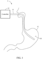
- FIG. 1 illustrates a schematic structure of an electrical stimulation device according to an example embodiment.
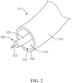
- FIG. 2 is a perspective view of an end structure of an elongated element of an electrical stimulation device according to an example embodiment.
- an electrical stimulation device 1 may be noninvasively inserted into an inner cavity of a target to apply electrical stimulation to the target.
- the target described herein may include a living creature, such as, for example, a human and an animal.
- the electrical stimulation device 1 may include a catheter 11 and a controller 12 configured to control the catheter 11.
- the catheter 11 may be inserted into an oral cavity of the target and move along an esophagus, and an end thereof may then be positioned in a gastrointestinal tract GI of the stomach and intestines G.
- the catheter 11 may apply electrical stimulation to the surface of the gastrointestinal tract GI.
- the catheter 11 may include an elongated element 111 and an electrical stimulator 120.
- the elongated element 111 may be inserted into the gastrointestinal tract GI while moving along the inner cavity of the target.
- the elongated element 111 may be provided in a form of a tube.
- the elongated element 111 may have a material suitable to be bent such that an end portion thereof readily approaches a desired portion.
- the elongated element 111 may be formed of a silicon material.
- the elongated element 111 may be formed of a water-resistant material.
- the elongated element 111 may include titanium.
- the elongated element 111 may have a length suitable for the end portion thereof to reach the gastrointestinal tract GI from the oral cavity of the target.
- the elongated element 111 may have a working channel 112.
- the working channel 112 may be formed inside the elongated element 111 along a longitudinal direction of the elongated element 111.
- the elongated element 111 may be hollow inside.
- the elongated element 111 may include an opening 113 and a closely attached portion 114.
- the opening 113 may be configured to communicate with the working channel 112.
- the opening 113 may allow entry and exit of the electrical stimulator 120 from the inside of the working channel 112 to the outside of the working channel 112 or from the outside of the working channel 112 to the inside of the working channel 112.
- the opening 113 may be formed at a distal end of the elongated element 111.
- the opening 113 may have a size suitable for the entry and exit of the electrical stimulator 120 to and from the outside or inside of the working channel 112.
- the opening 113 may be formed in a circle, but not limited thereto.
- the opening 113 may include an opening and closing element that selectively allows the entry or exit of the electrical stimulator 120.
- the opening and closing element may be provided in a structure of a plate membrane that covers at least a portion of the opening 113.
- the closely attached portion 114 may be configured to be closely attached to the surface of the inner cavity of the target.
- the closely attached portion 114 may be formed at an end of the elongated element 111 to surround the opening 113.
- a suction force of a predetermined pressure may act through the opening 113, and accordingly, close contact between the closely attached portion 114 and the surface of the inner cavity of the target may be maintained.
- the electrical stimulator 120 may apply electrical stimulation to a desired portion on the surface of the inner cavity of the target.
- the electrical stimulator 120 may be disposed in the working channel 112 formed inside the elongated element 111, and move along the working channel 112.
- the electrical stimulator 120 may include a longitudinal member 121 and a tip 122.
- the longitudinal member 121 may deploy or withdraw along the working channel 112.
- the longitudinal member 121 may deploy or withdraw while passing through the opening 113 formed at the distal end of the working channel 112.
- the longitudinal member 121 may extend in a longitudinal direction of the working channel 112.
- the longitudinal member 121 may include an electrical lead that transfers electrical stimulation to the surface of the inner cavity of the target.
- the electrical lead may extend along the longitudinal member 121 to be connected to a controller 12 outside a body.
- the tip 122 may apply electrical stimulation to the surface of the inner cavity of the target.
- the tip 122 may be provided at a distal end of the longitudinal member 121.
- the tip 122 may be provided in an elongated form extending from the distal end of the longitudinal member 121, but not limited thereto.
- a distal end of the tip 122 may be formed not to bore through the surface of the inner cavity of the target but to effectively transfer electrical stimulation to the surface of the inner cavity of the target.
- the tip 122 may include a conductive material through which electricity flows stably.
- the tip 122 may include an acid-resistant material. In such a case, the acid-resistant material may be coated on an outer surface of the tip 122.
- the controller 12 may control the catheter 11.
- the controller 12 may control a movement of the elongated element 111 along the inner cavity of the target.
- the elongated element 111 may be controlled by a user's manipulation.
- the controller 12 may control a deployment or withdrawal of the longitudinal member 121 along the working channel 112.
- the controller 12 may determine a degree of exposure of at least a portion of the longitudinal member 121 and the tip 122 to the outside of the working channel 112.
- the controller 12 may control the longitudinal member 121 not to deploy until the closely attached portion 114 is attached to the surface of the inner cavity of the target.
- the controller 12 may control the longitudinal member 121 to deploy until the tip 122 comes into contact with the surface of the inner cavity of the target.
- the controller 12 may determine an orientation of the electrical stimulator 120.
- the controller 12 may determine an orientation of at least a portion of the longitudinal member 121 to allow the portion of the longitudinal member 121 to be bent such that the tip 122 faces toward the surface of the inner cavity of the target.
- the longitudinal member 121 may be bent to have at least two bent portions.
- electrical stimulation may be applied to a desired portion on the surface of the inner cavity of the target.
- the controller 12 may control electrical energy to be applied by the tip 122 to the surface of the inner cavity of the target.
- the electrical energy may be determined by a voltage, a current, a frequency, an amplitude, a duty cycle, or the like.
- the controller 12 may vary the electrical energy to be applied by the tip 122.
- the controller 12 may generate a suction force from the outside of the working channel 112 to the inside of the working channel 112 through the opening 113. For example, when the closely attached portion 114 is attached to the surface of the inner cavity of the target, the controller 12 may allow air to be sucked into the inside of the working channel 113 through the opening 113 to maintain close contact between the closely attached portion 114 and the surface of the inner cavity of the target.
- FIG. 3 illustrates a movement of an elongated element of an electrical stimulation device along a gastrointestinal tract according to an example embodiment.
- the elongated element 111 may be controlled (by the controller 12 of FIG. 1 ) to move along the esophagus (indicated by GO) of the target.
- the longitudinal member 121 and the tip 122 of the electrical stimulator 120 may be controlled (by the controller 12 of FIG. 1 ) to be disposed inside the working channel 112 and not to be exposed to the outside of the working channel 112 through the opening 113. This may prevent the tip 122 from damaging a tissue of the target while the elongated element 111 is reaching a desired portion on the surface of the inner cavity of the target.
- FIG. 4 is a perspective view of a first configuration of an electrical stimulation device according to another example embodiment.
- FIG. 5 illustrates a first configuration of a plurality of electrical stimulators of FIG. 4 .
- FIG. 6 is a perspective view of a second configuration of an electrical stimulation device of FIG. 4 .
- FIG. 7 illustrates a second configuration of a plurality of electrical stimulators of FIG. 4 .
- a catheter 21 of an electrical stimulation device may include a plurality of electrical stimulators 120, dissimilar to what has been described above with reference to FIGS. 1 through 3 .
- the electrical stimulators 120 may be controlled by a controller (e.g., the controller 12 of FIG. 1 ) described above with reference to FIGS. 1 through 3 .
- the controller may control the electrical stimulators 120 independently for each of them.
- the independent controlling of the electrical stimulators 120 may include, for example, controlling deployments or withdrawals of respective longitudinal members 121 of the electrical stimulators 120 along the working channel 112, controlling degrees of exposure of the respective longitudinal members 121 and respective tips 122 of the electrical stimulators 120, controlling electrical energy to be applied to the respective tips 122 of the electrical stimulators 120, and controlling an arrangement, an orientation, and an overall shape of the electrical stimulators 120.
- the controller may independently control the deployments or withdrawals of the longitudinal members 121 in a longitudinal direction of the working channel 112 such that mutual spaces between the tips 122 of the electrical stimulators 120 are adjusted.
- the controller may determine the deployments or withdrawals of the longitudinal members 121 such that a mutual space between one pair among the tips 122 increases and a mutual space between another pair among the tips 122 decreases. Accordingly, an overall shape formed by the tips 122 may vary, and a range S1 or S2 in which the tips 122 apply electrical stimulation to a surface GIS of an inner cavity of a target may vary.
- the controller may control the electrical stimulators 120, in conjunction with the deployments or withdrawals of the longitudinal members 121, to form a certain shape.
- the controller may control the longitudinal members 121 such that the electrical stimulators 120 have a first configuration in which all of at least a portion of the longitudinal members 121 withdraw into the working channel 112 to contract. With the first configuration formed by the electrical stimulators 120, a range of electrical stimulation to be applied to the surface GIS of the inner cavity of the target may be relatively small. As illustrated in FIGS. 6 and 7 , the controller may control the longitudinal members 121 such that the electrical stimulators 120 have a second configuration in which all of at least a portion of the longitudinal members 121 deploy outside the working channel 112 to expand. With the second configuration formed by the electrical stimulators 120, a range of electrical stimulation to be applied to the surface GIS of the inner cavity of the target may be relatively great.
- the controller may control the deployments and withdrawals of the longitudinal members 121 in a combined way such that the electrical stimulators 120 have a shape between the first configuration and the second configuration. Accordingly, a range of electrical stimulation to be applied to the surface of the inner cavity of the target may have a value between S1 and S2.
- the controller may control the longitudinal members 121 to deploy in the longitudinal direction of the working channel 112 until all the tips 122 come into contact with the surface of the inner cavity of the target. This may ensure the application of a desired range of electrical stimulation to the surface of the inner cavity of the target.
- the controller may independently adjust electrical energy to be applied by the tips 122.
- the controller may set different potentials to be applied to at least two of the tips 122.
- the tips 122 apply electrical stimulation to the surface GIS of the inner cavity of the target, a current flow from one of the tips 122 having a first potential to another one of the tips 122 having a second potential different from the first potential may be induced. This may implement various forms of electrical current flows on the surface GIS of the inner cavity of the target.
- the controller may set different duty cycles, frequencies, currents, and the like of electrical signals to be applied to at least two of the tips 122, thereby implementing various forms of electrical current flows on the surface GIS of the inner cavity of the target to which electrical stimulation is to be applied.
Landscapes
- Health & Medical Sciences (AREA)
- Life Sciences & Earth Sciences (AREA)
- Veterinary Medicine (AREA)
- Biomedical Technology (AREA)
- Nuclear Medicine, Radiotherapy & Molecular Imaging (AREA)
- Radiology & Medical Imaging (AREA)
- Engineering & Computer Science (AREA)
- Animal Behavior & Ethology (AREA)
- General Health & Medical Sciences (AREA)
- Public Health (AREA)
- Heart & Thoracic Surgery (AREA)
- Gastroenterology & Hepatology (AREA)
- Cardiology (AREA)
- Neurology (AREA)
- Surgery (AREA)
- Physics & Mathematics (AREA)
- Biophysics (AREA)
- Optics & Photonics (AREA)
- Pathology (AREA)
- Medical Informatics (AREA)
- Molecular Biology (AREA)
- Electrotherapy Devices (AREA)
Abstract
Description
- Example embodiments relate to an electrical stimulation device.
- A functional gastrointestinal disorder among gastrointestinal disorders is a chronic or relapsing disorder developed in approximately 40% of adults. Currently, various attempts including, for example, medication, endoscopic procedures, and surgical operations, are being made to treat the functional gastrointestinal disorder and metabolic obesity. However, such methods may not have significant effects, and may cost patients a lot and invite complications. Accordingly, an electrical gastrointestinal stimulation technology is being developed as a technology for treating a functional gastrointestinal disorder or disease. For example,
Korean Patent Publication No. 10-2018-0023966 - An aspect provides an electrical stimulation device that is used along with an endoscope and noninvasively applies electrical stimulation to a desired portion on a surface of a target.
- According to an example embodiment, there is provided an electrical stimulation device including an elongated element having a working channel, a plurality of electrical stimulators including respective longitudinal members each extending in a longitudinal direction of the working channel and respective tips each provided at a distal end of the longitudinal members and configured to apply electrical stimulation to a target, and a controller configured to independently control the electrical stimulators to vary a range of electrical simulation to be applied to the target.
- The controller may independently control a deployment or a withdrawal of the longitudinal members in the longitudinal direction of the working channel such that a space between the tips is adjusted.
- The controller may control the longitudinal members to have a first configuration in which all of at least a portion of the longitudinal members withdraw into the working channel to contract and have a second configuration in which all of at least a portion of the longitudinal members deploy outside the working channel to expand.
- The controller may control the longitudinal members to deploy in the longitudinal direction of the working channel until all the tips come into contact with a surface of the target.
- The controller may apply different potentials to at least two of the tips.
- The controller may control a movement of the elongated element along an inner cavity of the target, and control the longitudinal members such that the tips are not exposed to the inner cavity of the target from the working channel during the movement of the elongated element along the inner cavity of the target.
- The elongated element may include an opening through which the longitudinal members pass, and a closely attached portion configured to surround the opening and configured to be closely attached to the surface of the target.
- When the closely attached portion is closely attached to the surface of the target, the controller may suck air into the working channel through the opening.
- According to example embodiments described herein, an electrical stimulation device may be used together with an endoscope and noninvasively apply electrical stimulation to a desired portion on a surface of a target.
- The effects of the electrical stimulation device are not limited to what has been described above, and other additional aspects of example embodiments will be set forth in part in the description which follows and, in part, will be apparent from the description, or may be learned by practice of the disclosure.
-
-
FIG. 1 illustrates a schematic structure of an electrical stimulation device according to an example embodiment. -
FIG. 2 is a perspective view of an end structure of an elongated element of an electrical stimulation device according to an example embodiment. -
FIG. 3 illustrates a movement of an elongated element of an electrical stimulation device along a gastrointestinal tract according to an example embodiment. -
FIG. 4 is a perspective view of a first configuration of an electrical stimulation device according to another example embodiment. -
FIG. 5 illustrates a first configuration of a plurality of electrical stimulators ofFIG. 4 . -
FIG. 6 is a perspective view of a second configuration of an electrical stimulation device ofFIG. 4 . -
FIG. 7 illustrates a second configuration of a plurality of electrical stimulators ofFIG. 4 . - Hereinafter, some example embodiments will be described in detail with reference to the accompanying drawings. However, various alterations and modifications may be made to the example embodiments. The example embodiments are not construed as limited to the disclosure and should be understood to include all changes, equivalents, and replacements within the idea and the technical scope of the disclosure.
- The terminology used herein is for the purpose of describing particular examples only and is not to be limiting of the examples. As used herein, the singular forms "a", "an", and "the" are intended to include the plural forms as well, unless the context clearly indicates otherwise. It will be further understood that the terms "comprises/comprising" and/or "includes/including" when used herein, specify the presence of stated features, integers, steps, operations, elements, and/or components, but do not preclude the presence or addition of one or more other features, integers, steps, operations, elements, components and/or groups thereof.
- In addition, terms such as first, second, A, B, (a), (b), and the like may be used herein to describe components. Each of these terminologies is not used to define an essence, order, or sequence of a corresponding component but used merely to distinguish the corresponding component from other component(s).
- It should be noted that if it is described in the specification that one component is "connected," "coupled," or "joined" to another component, a third component may be "connected," "coupled," and "joined" between the first and second components, although the first component may be directly connected, coupled or joined to the second component.
- Unless otherwise defined, all terms used herein including technical or scientific terms have the same meanings as those generally understood consistent with and after an understanding of the present disclosure. Terms, such as those defined in commonly used dictionaries, should be construed to have meanings matching with contextual meanings in the relevant art and the present disclosure, and are not to be construed as an ideal or excessively formal meaning unless otherwise defined herein.
- Hereinafter, the example embodiments will be described in detail with reference to the accompanying drawings. When describing the example embodiments with reference to the accompanying drawings, like reference numerals refer to like components and a repeated description related thereto will be omitted for increased clarity and conciseness.
-
FIG. 1 illustrates a schematic structure of an electrical stimulation device according to an example embodiment.FIG. 2 is a perspective view of an end structure of an elongated element of an electrical stimulation device according to an example embodiment. - Referring to
FIGS. 1 and2 , according to an example embodiment, anelectrical stimulation device 1 may be noninvasively inserted into an inner cavity of a target to apply electrical stimulation to the target. The target described herein may include a living creature, such as, for example, a human and an animal. Theelectrical stimulation device 1 may include acatheter 11 and acontroller 12 configured to control thecatheter 11. Thecatheter 11 may be inserted into an oral cavity of the target and move along an esophagus, and an end thereof may then be positioned in a gastrointestinal tract GI of the stomach and intestines G. Thecatheter 11 may apply electrical stimulation to the surface of the gastrointestinal tract GI. - The
catheter 11 may include anelongated element 111 and anelectrical stimulator 120. - The
elongated element 111 may be inserted into the gastrointestinal tract GI while moving along the inner cavity of the target. Theelongated element 111 may be provided in a form of a tube. Theelongated element 111 may have a material suitable to be bent such that an end portion thereof readily approaches a desired portion. For example, theelongated element 111 may be formed of a silicon material. Also, theelongated element 111 may be formed of a water-resistant material. For example, theelongated element 111 may include titanium. Theelongated element 111 may have a length suitable for the end portion thereof to reach the gastrointestinal tract GI from the oral cavity of the target. - The
elongated element 111 may have a workingchannel 112. The workingchannel 112 may be formed inside theelongated element 111 along a longitudinal direction of theelongated element 111. Thus, theelongated element 111 may be hollow inside. - The
elongated element 111 may include anopening 113 and a closely attachedportion 114. - The opening 113 may be configured to communicate with the working
channel 112. The opening 113 may allow entry and exit of theelectrical stimulator 120 from the inside of the workingchannel 112 to the outside of the workingchannel 112 or from the outside of the workingchannel 112 to the inside of the workingchannel 112. Theopening 113 may be formed at a distal end of theelongated element 111. Theopening 113 may have a size suitable for the entry and exit of theelectrical stimulator 120 to and from the outside or inside of the workingchannel 112. Theopening 113 may be formed in a circle, but not limited thereto. - The
opening 113 may include an opening and closing element that selectively allows the entry or exit of theelectrical stimulator 120. For example, the opening and closing element may be provided in a structure of a plate membrane that covers at least a portion of theopening 113. - The closely
attached portion 114 may be configured to be closely attached to the surface of the inner cavity of the target. The closelyattached portion 114 may be formed at an end of theelongated element 111 to surround theopening 113. When the closelyattached portion 114 is attached to the surface of the inner cavity of the target, a suction force of a predetermined pressure may act through theopening 113, and accordingly, close contact between the closelyattached portion 114 and the surface of the inner cavity of the target may be maintained. - The
electrical stimulator 120 may apply electrical stimulation to a desired portion on the surface of the inner cavity of the target. Theelectrical stimulator 120 may be disposed in the workingchannel 112 formed inside theelongated element 111, and move along the workingchannel 112. - The
electrical stimulator 120 may include alongitudinal member 121 and atip 122. - The
longitudinal member 121 may deploy or withdraw along the workingchannel 112. Thelongitudinal member 121 may deploy or withdraw while passing through theopening 113 formed at the distal end of the workingchannel 112. Thelongitudinal member 121 may extend in a longitudinal direction of the workingchannel 112. Thelongitudinal member 121 may include an electrical lead that transfers electrical stimulation to the surface of the inner cavity of the target. The electrical lead may extend along thelongitudinal member 121 to be connected to acontroller 12 outside a body. - The
tip 122 may apply electrical stimulation to the surface of the inner cavity of the target. Thetip 122 may be provided at a distal end of thelongitudinal member 121. Thetip 122 may be provided in an elongated form extending from the distal end of thelongitudinal member 121, but not limited thereto. A distal end of thetip 122 may be formed not to bore through the surface of the inner cavity of the target but to effectively transfer electrical stimulation to the surface of the inner cavity of the target. Thetip 122 may include a conductive material through which electricity flows stably. In addition, thetip 122 may include an acid-resistant material. In such a case, the acid-resistant material may be coated on an outer surface of thetip 122. - The
controller 12 may control thecatheter 11. For example, thecontroller 12 may control a movement of theelongated element 111 along the inner cavity of the target. Alternatively, theelongated element 111 may be controlled by a user's manipulation. - The
controller 12 may control a deployment or withdrawal of thelongitudinal member 121 along the workingchannel 112. When thelongitudinal member 121 deploys or withdraws, thecontroller 12 may determine a degree of exposure of at least a portion of thelongitudinal member 121 and thetip 122 to the outside of the workingchannel 112. Thecontroller 12 may control thelongitudinal member 121 not to deploy until the closelyattached portion 114 is attached to the surface of the inner cavity of the target. Thecontroller 12 may control thelongitudinal member 121 to deploy until thetip 122 comes into contact with the surface of the inner cavity of the target. - The
controller 12 may determine an orientation of theelectrical stimulator 120. In this case, thecontroller 12 may determine an orientation of at least a portion of thelongitudinal member 121 to allow the portion of thelongitudinal member 121 to be bent such that thetip 122 faces toward the surface of the inner cavity of the target. For example, thelongitudinal member 121 may be bent to have at least two bent portions. As the orientation of thelongitudinal member 121 is controlled as described above, electrical stimulation may be applied to a desired portion on the surface of the inner cavity of the target. - The
controller 12 may control electrical energy to be applied by thetip 122 to the surface of the inner cavity of the target. The electrical energy may be determined by a voltage, a current, a frequency, an amplitude, a duty cycle, or the like. In addition, thecontroller 12 may vary the electrical energy to be applied by thetip 122. - The
controller 12 may generate a suction force from the outside of the workingchannel 112 to the inside of the workingchannel 112 through theopening 113. For example, when the closelyattached portion 114 is attached to the surface of the inner cavity of the target, thecontroller 12 may allow air to be sucked into the inside of the workingchannel 113 through theopening 113 to maintain close contact between the closelyattached portion 114 and the surface of the inner cavity of the target. -
FIG. 3 illustrates a movement of an elongated element of an electrical stimulation device along a gastrointestinal tract according to an example embodiment. - Referring to
FIG. 3 , theelongated element 111 may be controlled (by thecontroller 12 ofFIG. 1 ) to move along the esophagus (indicated by GO) of the target. In this case, thelongitudinal member 121 and thetip 122 of theelectrical stimulator 120 may be controlled (by thecontroller 12 ofFIG. 1 ) to be disposed inside the workingchannel 112 and not to be exposed to the outside of the workingchannel 112 through theopening 113. This may prevent thetip 122 from damaging a tissue of the target while theelongated element 111 is reaching a desired portion on the surface of the inner cavity of the target. -
FIG. 4 is a perspective view of a first configuration of an electrical stimulation device according to another example embodiment.FIG. 5 illustrates a first configuration of a plurality of electrical stimulators ofFIG. 4 .FIG. 6 is a perspective view of a second configuration of an electrical stimulation device ofFIG. 4 .FIG. 7 illustrates a second configuration of a plurality of electrical stimulators ofFIG. 4 . - Referring to
FIGS. 4 through 7 , according to another example embodiment, acatheter 21 of an electrical stimulation device may include a plurality ofelectrical stimulators 120, dissimilar to what has been described above with reference toFIGS. 1 through 3 . Theelectrical stimulators 120 may be controlled by a controller (e.g., thecontroller 12 ofFIG. 1 ) described above with reference toFIGS. 1 through 3 . - The controller may control the
electrical stimulators 120 independently for each of them. The independent controlling of theelectrical stimulators 120 may include, for example, controlling deployments or withdrawals of respectivelongitudinal members 121 of theelectrical stimulators 120 along the workingchannel 112, controlling degrees of exposure of the respectivelongitudinal members 121 andrespective tips 122 of theelectrical stimulators 120, controlling electrical energy to be applied to therespective tips 122 of theelectrical stimulators 120, and controlling an arrangement, an orientation, and an overall shape of theelectrical stimulators 120. - The controller may independently control the deployments or withdrawals of the
longitudinal members 121 in a longitudinal direction of the workingchannel 112 such that mutual spaces between thetips 122 of theelectrical stimulators 120 are adjusted. For example, the controller may determine the deployments or withdrawals of thelongitudinal members 121 such that a mutual space between one pair among thetips 122 increases and a mutual space between another pair among thetips 122 decreases. Accordingly, an overall shape formed by thetips 122 may vary, and a range S1 or S2 in which thetips 122 apply electrical stimulation to a surface GIS of an inner cavity of a target may vary. - The controller may control the
electrical stimulators 120, in conjunction with the deployments or withdrawals of thelongitudinal members 121, to form a certain shape. - As illustrated in
FIGS. 4 and5 , the controller may control thelongitudinal members 121 such that theelectrical stimulators 120 have a first configuration in which all of at least a portion of thelongitudinal members 121 withdraw into the workingchannel 112 to contract. With the first configuration formed by theelectrical stimulators 120, a range of electrical stimulation to be applied to the surface GIS of the inner cavity of the target may be relatively small. As illustrated inFIGS. 6 and7 , the controller may control thelongitudinal members 121 such that theelectrical stimulators 120 have a second configuration in which all of at least a portion of thelongitudinal members 121 deploy outside the workingchannel 112 to expand. With the second configuration formed by theelectrical stimulators 120, a range of electrical stimulation to be applied to the surface GIS of the inner cavity of the target may be relatively great. The controller may control the deployments and withdrawals of thelongitudinal members 121 in a combined way such that theelectrical stimulators 120 have a shape between the first configuration and the second configuration. Accordingly, a range of electrical stimulation to be applied to the surface of the inner cavity of the target may have a value between S1 and S2. - The controller may control the
longitudinal members 121 to deploy in the longitudinal direction of the workingchannel 112 until all thetips 122 come into contact with the surface of the inner cavity of the target. This may ensure the application of a desired range of electrical stimulation to the surface of the inner cavity of the target. - The controller may independently adjust electrical energy to be applied by the
tips 122. For example, the controller may set different potentials to be applied to at least two of thetips 122. When thetips 122 apply electrical stimulation to the surface GIS of the inner cavity of the target, a current flow from one of thetips 122 having a first potential to another one of thetips 122 having a second potential different from the first potential may be induced. This may implement various forms of electrical current flows on the surface GIS of the inner cavity of the target. Similarly, the controller may set different duty cycles, frequencies, currents, and the like of electrical signals to be applied to at least two of thetips 122, thereby implementing various forms of electrical current flows on the surface GIS of the inner cavity of the target to which electrical stimulation is to be applied. - While this disclosure includes specific examples, it will be apparent to one of ordinary skill in the art that various changes in form and details may be made in these examples without departing from the spirit and scope of the claims and their equivalents. The examples described herein are to be considered in a descriptive sense only, and not for purposes of limitation. Suitable results may be achieved if the described techniques are performed in a different order, and/or if components in a described system, architecture, device, or circuit are combined in a different manner and/or replaced or supplemented by other components or their equivalents.
- Therefore, the scope of the disclosure is defined not by the detailed description, but by the claims and their equivalents, and all variations within the scope of the claims and their equivalents are to be construed as being included in the disclosure.
Claims (8)
- An electrical stimulation device, comprising:an elongated element having a working channel;a plurality of electrical stimulators comprising respective longitudinal members each extending in a longitudinal direction of the working channel, and respective tips each provided at a distal end of the longitudinal members and configured to apply electrical stimulation to a target; anda controller configured to independently control the electrical stimulators to vary a range of electrical simulation to be applied to the target.
- The electrical stimulation device of claim 1, wherein the controller is configured to independently control a deployment or a withdrawal of the longitudinal members in the longitudinal direction of the working channel such that a space between the tips is adjusted.
- The electrical stimulation device of claim 2, wherein the controller is configured to control the longitudinal members to have a first configuration in which all of at least a portion of the longitudinal members withdraw into the working channel to contract and have a second configuration in which all of at least a portion of the longitudinal members deploy outside the working channel to expand.
- The electrical stimulation device of claim 2, wherein the controller is configured to control the longitudinal members to deploy in the longitudinal direction of the working channel until all the tips come into contact with a surface of the target.
- The electrical stimulation device of claim 1, wherein the controller is configured to apply different potentials to at least two of the tips.
- The electrical stimulation device of claim 1, wherein the controller is configured to control a movement of the elongated element along an inner cavity of the target, and control the longitudinal members such that the tips are not exposed to the inner cavity of the target from the working channel during the movement of the elongated element along the inner cavity of the target.
- The electrical stimulation device of claim 1, wherein the elongated element comprises:an opening through which the longitudinal members pass; anda closely attached portion configured to surround the opening and configured to be closely attached to a surface of the target.
- The electrical stimulation device of claim 7, wherein, when the closely attached portion is closely attached to the surface of the target, the controller is configured to suck air into the working channel through the opening.
Applications Claiming Priority (2)
| Application Number | Priority Date | Filing Date | Title |
|---|---|---|---|
| KR1020190053286A KR102233408B1 (en) | 2019-05-07 | 2019-05-07 | Apparatus for electrically stimulation |
| PCT/KR2020/095046 WO2020226474A1 (en) | 2019-05-07 | 2020-03-19 | Electrical stimulation device |
Publications (3)
| Publication Number | Publication Date |
|---|---|
| EP3967363A1 true EP3967363A1 (en) | 2022-03-16 |
| EP3967363A4 EP3967363A4 (en) | 2023-01-18 |
| EP3967363B1 EP3967363B1 (en) | 2026-01-21 |
Family
ID=73050636
Family Applications (1)
| Application Number | Title | Priority Date | Filing Date |
|---|---|---|---|
| EP20801564.4A Active EP3967363B1 (en) | 2019-05-07 | 2020-03-19 | Electrical stimulation device |
Country Status (4)
| Country | Link |
|---|---|
| US (1) | US12023483B2 (en) |
| EP (1) | EP3967363B1 (en) |
| KR (1) | KR102233408B1 (en) |
| WO (1) | WO2020226474A1 (en) |
Family Cites Families (10)
| Publication number | Priority date | Publication date | Assignee | Title |
|---|---|---|---|---|
| US6235023B1 (en) | 1995-08-15 | 2001-05-22 | Rita Medical Systems, Inc. | Cell necrosis apparatus |
| US6535764B2 (en) | 2001-05-01 | 2003-03-18 | Intrapace, Inc. | Gastric treatment and diagnosis device and method |
| JP2008514363A (en) * | 2004-09-30 | 2008-05-08 | ボストン サイエンティフィック リミテッド | Multifunctional endoscope system for use in electrosurgical applications |
| CN101495177A (en) * | 2005-12-02 | 2009-07-29 | 突触生物医学有限公司 | Transvisceral neurostimulation mapping device and method |
| EP2432412A2 (en) | 2009-05-20 | 2012-03-28 | Herlev Hospital | Electroporation device with improved tip and electrode support |
| US20160015451A1 (en) * | 2009-09-22 | 2016-01-21 | Mederi Therapeutics, Inc. | Systems and methods for treating tissue with radiofrequency energy |
| US8753340B2 (en) | 2012-03-01 | 2014-06-17 | Mark D Noar | Catheter structure and method for locating tissue in a body organ and simultaneously delivering therapy and evaluating the therapy delivered |
| KR101314574B1 (en) | 2012-11-16 | 2013-10-07 | 주식회사 루트로닉 | A treatment apparutus using radio frequency energy |
| JP2018522650A (en) | 2015-06-28 | 2018-08-16 | イラン,ヤロン | Apparatus for gastrointestinal stimulation and use thereof |
| KR102180645B1 (en) * | 2017-09-06 | 2020-11-20 | 고려대학교 산학협력단 | Needle type electrode apparatus for endoscopic irreversible electroporation |
-
2019
- 2019-05-07 KR KR1020190053286A patent/KR102233408B1/en active Active
-
2020
- 2020-03-19 WO PCT/KR2020/095046 patent/WO2020226474A1/en not_active Ceased
- 2020-03-19 US US17/609,388 patent/US12023483B2/en active Active
- 2020-03-19 EP EP20801564.4A patent/EP3967363B1/en active Active
Also Published As
| Publication number | Publication date |
|---|---|
| US20220218984A1 (en) | 2022-07-14 |
| WO2020226474A1 (en) | 2020-11-12 |
| KR20200128988A (en) | 2020-11-17 |
| EP3967363A4 (en) | 2023-01-18 |
| KR102233408B1 (en) | 2021-03-29 |
| EP3967363B1 (en) | 2026-01-21 |
| KR102233408B9 (en) | 2021-09-17 |
| US12023483B2 (en) | 2024-07-02 |
Similar Documents
| Publication | Publication Date | Title |
|---|---|---|
| US8021384B2 (en) | Extending intrabody capsule | |
| US7509175B2 (en) | Method and devices for stimulation of an organ with the use of a transectionally placed guide wire | |
| US20220072300A1 (en) | Method and apparatus for minimally invasive implantable modulators | |
| US20140051907A1 (en) | Ventricular function assisting devices and methods of use thereof | |
| US20080312712A1 (en) | Implantable Devices and Methods for Stimulation of Cardiac or Other Tissues | |
| US20090018606A1 (en) | Methods and Devices for Stimulation of an Organ with the Use of a Transectionally Placed Guide Wire | |
| JP2015524310A (en) | Flexible expandable electrode and method for intraluminal delivery of pulsed power | |
| US8167640B2 (en) | Flexible connector for implantable electrical stimulation lead | |
| JP6605594B2 (en) | Catheter and manufacturing method thereof | |
| US12023483B2 (en) | Electrical stimulation device | |
| US20090210040A1 (en) | Variable length medical electrical stimulation lead | |
| Park et al. | New method of moving control for wireless endoscopic capsule using electrical stimuli | |
| JP5095261B2 (en) | Medical device having a catheter | |
| US8133249B2 (en) | Devices and methods for stricture dilation | |
| US20230277856A1 (en) | An intraluminal contraction augmentation system | |
| EP1944056A1 (en) | Myocardial electrode | |
| CN113993575B (en) | In-vivo guide member | |
| US12569674B2 (en) | Electrical stimulation system | |
| US20150272813A1 (en) | Systems and methods for electrical stimulation of the gastrointestinal tract for treatment of post-operative ileus | |
| WO2025238474A1 (en) | Furlable electrode array | |
| WO2021201076A1 (en) | Balloon-equipped catheter | |
| CN116249494A (en) | Endoscopic magnetic anastomosis system, method and device for forming anastomosis |
Legal Events
| Date | Code | Title | Description |
|---|---|---|---|
| STAA | Information on the status of an ep patent application or granted ep patent |
Free format text: STATUS: THE INTERNATIONAL PUBLICATION HAS BEEN MADE |
|
| PUAI | Public reference made under article 153(3) epc to a published international application that has entered the european phase |
Free format text: ORIGINAL CODE: 0009012 |
|
| STAA | Information on the status of an ep patent application or granted ep patent |
Free format text: STATUS: REQUEST FOR EXAMINATION WAS MADE |
|
| 17P | Request for examination filed |
Effective date: 20211129 |
|
| AK | Designated contracting states |
Kind code of ref document: A1 Designated state(s): AL AT BE BG CH CY CZ DE DK EE ES FI FR GB GR HR HU IE IS IT LI LT LU LV MC MK MT NL NO PL PT RO RS SE SI SK SM TR |
|
| DAV | Request for validation of the european patent (deleted) | ||
| DAX | Request for extension of the european patent (deleted) | ||
| REG | Reference to a national code |
Ref country code: DE Ref legal event code: R079 Free format text: PREVIOUS MAIN CLASS: A61N0001360000 Ipc: A61N0001050000 Ref document number: 602020065585 Country of ref document: DE |
|
| A4 | Supplementary search report drawn up and despatched |
Effective date: 20221214 |
|
| RIC1 | Information provided on ipc code assigned before grant |
Ipc: A61B 18/00 20060101ALN20221209BHEP Ipc: A61B 18/14 20060101ALN20221209BHEP Ipc: A61B 1/273 20060101ALN20221209BHEP Ipc: A61N 1/36 20060101ALI20221209BHEP Ipc: A61N 1/05 20060101AFI20221209BHEP |
|
| STAA | Information on the status of an ep patent application or granted ep patent |
Free format text: STATUS: EXAMINATION IS IN PROGRESS |
|
| 17Q | First examination report despatched |
Effective date: 20250129 |
|
| RIC1 | Information provided on ipc code assigned before grant |
Ipc: A61N 1/05 20060101AFI20250819BHEP Ipc: A61N 1/36 20060101ALI20250819BHEP Ipc: A61B 1/273 20060101ALN20250819BHEP Ipc: A61B 18/14 20060101ALN20250819BHEP Ipc: A61B 18/00 20060101ALN20250819BHEP |
|
| GRAP | Despatch of communication of intention to grant a patent |
Free format text: ORIGINAL CODE: EPIDOSNIGR1 |
|
| STAA | Information on the status of an ep patent application or granted ep patent |
Free format text: STATUS: GRANT OF PATENT IS INTENDED |
|
| INTG | Intention to grant announced |
Effective date: 20250929 |
|
| GRAS | Grant fee paid |
Free format text: ORIGINAL CODE: EPIDOSNIGR3 |
|
| GRAA | (expected) grant |
Free format text: ORIGINAL CODE: 0009210 |
|
| STAA | Information on the status of an ep patent application or granted ep patent |
Free format text: STATUS: THE PATENT HAS BEEN GRANTED |
|
| AK | Designated contracting states |
Kind code of ref document: B1 Designated state(s): AL AT BE BG CH CY CZ DE DK EE ES FI FR GB GR HR HU IE IS IT LI LT LU LV MC MK MT NL NO PL PT RO RS SE SI SK SM TR |
|
| REG | Reference to a national code |
Ref country code: CH Ref legal event code: F10 Free format text: ST27 STATUS EVENT CODE: U-0-0-F10-F00 (AS PROVIDED BY THE NATIONAL OFFICE) Effective date: 20260121 |
|
| REG | Reference to a national code |
Ref country code: DE Ref legal event code: R096 Ref document number: 602020065585 Country of ref document: DE |
|
| REG | Reference to a national code |
Ref country code: IE Ref legal event code: FG4D |
|
| PGFP | Annual fee paid to national office [announced via postgrant information from national office to epo] |
Ref country code: DE Payment date: 20260127 Year of fee payment: 7 |
|
| PGFP | Annual fee paid to national office [announced via postgrant information from national office to epo] |
Ref country code: FR Payment date: 20260127 Year of fee payment: 7 |