EP3967256A1 - End effector assemblies for surgical instruments - Google Patents
End effector assemblies for surgical instruments Download PDFInfo
- Publication number
- EP3967256A1 EP3967256A1 EP21196716.1A EP21196716A EP3967256A1 EP 3967256 A1 EP3967256 A1 EP 3967256A1 EP 21196716 A EP21196716 A EP 21196716A EP 3967256 A1 EP3967256 A1 EP 3967256A1
- Authority
- EP
- European Patent Office
- Prior art keywords
- jaw
- jaw member
- end effector
- internal spacer
- effector assembly
- Prior art date
- Legal status (The legal status is an assumption and is not a legal conclusion. Google has not performed a legal analysis and makes no representation as to the accuracy of the status listed.)
- Granted
Links
Images





Classifications
-
- A—HUMAN NECESSITIES
- A61—MEDICAL OR VETERINARY SCIENCE; HYGIENE
- A61B—DIAGNOSIS; SURGERY; IDENTIFICATION
- A61B18/00—Surgical instruments, devices or methods for transferring non-mechanical forms of energy to or from the body
- A61B18/04—Surgical instruments, devices or methods for transferring non-mechanical forms of energy to or from the body by heating
- A61B18/12—Surgical instruments, devices or methods for transferring non-mechanical forms of energy to or from the body by heating by passing a current through the tissue to be heated, e.g. high-frequency current
- A61B18/14—Probes or electrodes therefor
- A61B18/1442—Probes having pivoting end effectors, e.g. forceps
- A61B18/1445—Probes having pivoting end effectors, e.g. forceps at the distal end of a shaft, e.g. forceps or scissors at the end of a rigid rod
-
- A—HUMAN NECESSITIES
- A61—MEDICAL OR VETERINARY SCIENCE; HYGIENE
- A61B—DIAGNOSIS; SURGERY; IDENTIFICATION
- A61B18/00—Surgical instruments, devices or methods for transferring non-mechanical forms of energy to or from the body
- A61B18/04—Surgical instruments, devices or methods for transferring non-mechanical forms of energy to or from the body by heating
- A61B18/12—Surgical instruments, devices or methods for transferring non-mechanical forms of energy to or from the body by heating by passing a current through the tissue to be heated, e.g. high-frequency current
- A61B18/14—Probes or electrodes therefor
- A61B18/1442—Probes having pivoting end effectors, e.g. forceps
-
- A—HUMAN NECESSITIES
- A61—MEDICAL OR VETERINARY SCIENCE; HYGIENE
- A61B—DIAGNOSIS; SURGERY; IDENTIFICATION
- A61B34/00—Computer-aided surgery; Manipulators or robots specially adapted for use in surgery
- A61B34/30—Surgical robots
-
- A—HUMAN NECESSITIES
- A61—MEDICAL OR VETERINARY SCIENCE; HYGIENE
- A61B—DIAGNOSIS; SURGERY; IDENTIFICATION
- A61B18/00—Surgical instruments, devices or methods for transferring non-mechanical forms of energy to or from the body
- A61B18/04—Surgical instruments, devices or methods for transferring non-mechanical forms of energy to or from the body by heating
- A61B18/12—Surgical instruments, devices or methods for transferring non-mechanical forms of energy to or from the body by heating by passing a current through the tissue to be heated, e.g. high-frequency current
- A61B18/14—Probes or electrodes therefor
- A61B18/1482—Probes or electrodes therefor having a long rigid shaft for accessing the inner body transcutaneously in minimal invasive surgery, e.g. laparoscopy
-
- A—HUMAN NECESSITIES
- A61—MEDICAL OR VETERINARY SCIENCE; HYGIENE
- A61B—DIAGNOSIS; SURGERY; IDENTIFICATION
- A61B34/00—Computer-aided surgery; Manipulators or robots specially adapted for use in surgery
- A61B34/30—Surgical robots
- A61B34/37—Leader-follower robots
-
- A—HUMAN NECESSITIES
- A61—MEDICAL OR VETERINARY SCIENCE; HYGIENE
- A61B—DIAGNOSIS; SURGERY; IDENTIFICATION
- A61B34/00—Computer-aided surgery; Manipulators or robots specially adapted for use in surgery
- A61B34/70—Manipulators specially adapted for use in surgery
-
- A—HUMAN NECESSITIES
- A61—MEDICAL OR VETERINARY SCIENCE; HYGIENE
- A61B—DIAGNOSIS; SURGERY; IDENTIFICATION
- A61B34/00—Computer-aided surgery; Manipulators or robots specially adapted for use in surgery
- A61B34/70—Manipulators specially adapted for use in surgery
- A61B34/74—Manipulators with manual electric input means
-
- A—HUMAN NECESSITIES
- A61—MEDICAL OR VETERINARY SCIENCE; HYGIENE
- A61B—DIAGNOSIS; SURGERY; IDENTIFICATION
- A61B18/00—Surgical instruments, devices or methods for transferring non-mechanical forms of energy to or from the body
- A61B2018/00053—Mechanical features of the instrument of device
- A61B2018/00059—Material properties
- A61B2018/00071—Electrical conductivity
- A61B2018/00077—Electrical conductivity high, i.e. electrically conducting
-
- A—HUMAN NECESSITIES
- A61—MEDICAL OR VETERINARY SCIENCE; HYGIENE
- A61B—DIAGNOSIS; SURGERY; IDENTIFICATION
- A61B18/00—Surgical instruments, devices or methods for transferring non-mechanical forms of energy to or from the body
- A61B2018/00571—Surgical instruments, devices or methods for transferring non-mechanical forms of energy to or from the body for achieving a particular surgical effect
- A61B2018/00589—Coagulation
-
- A—HUMAN NECESSITIES
- A61—MEDICAL OR VETERINARY SCIENCE; HYGIENE
- A61B—DIAGNOSIS; SURGERY; IDENTIFICATION
- A61B18/00—Surgical instruments, devices or methods for transferring non-mechanical forms of energy to or from the body
- A61B2018/00571—Surgical instruments, devices or methods for transferring non-mechanical forms of energy to or from the body for achieving a particular surgical effect
- A61B2018/00595—Cauterization
-
- A—HUMAN NECESSITIES
- A61—MEDICAL OR VETERINARY SCIENCE; HYGIENE
- A61B—DIAGNOSIS; SURGERY; IDENTIFICATION
- A61B18/00—Surgical instruments, devices or methods for transferring non-mechanical forms of energy to or from the body
- A61B2018/00571—Surgical instruments, devices or methods for transferring non-mechanical forms of energy to or from the body for achieving a particular surgical effect
- A61B2018/00601—Cutting
-
- A—HUMAN NECESSITIES
- A61—MEDICAL OR VETERINARY SCIENCE; HYGIENE
- A61B—DIAGNOSIS; SURGERY; IDENTIFICATION
- A61B18/00—Surgical instruments, devices or methods for transferring non-mechanical forms of energy to or from the body
- A61B2018/00571—Surgical instruments, devices or methods for transferring non-mechanical forms of energy to or from the body for achieving a particular surgical effect
- A61B2018/0063—Sealing
-
- A—HUMAN NECESSITIES
- A61—MEDICAL OR VETERINARY SCIENCE; HYGIENE
- A61B—DIAGNOSIS; SURGERY; IDENTIFICATION
- A61B18/00—Surgical instruments, devices or methods for transferring non-mechanical forms of energy to or from the body
- A61B18/04—Surgical instruments, devices or methods for transferring non-mechanical forms of energy to or from the body by heating
- A61B18/12—Surgical instruments, devices or methods for transferring non-mechanical forms of energy to or from the body by heating by passing a current through the tissue to be heated, e.g. high-frequency current
- A61B18/14—Probes or electrodes therefor
- A61B18/1442—Probes having pivoting end effectors, e.g. forceps
- A61B2018/1452—Probes having pivoting end effectors, e.g. forceps including means for cutting
-
- A—HUMAN NECESSITIES
- A61—MEDICAL OR VETERINARY SCIENCE; HYGIENE
- A61B—DIAGNOSIS; SURGERY; IDENTIFICATION
- A61B18/00—Surgical instruments, devices or methods for transferring non-mechanical forms of energy to or from the body
- A61B18/04—Surgical instruments, devices or methods for transferring non-mechanical forms of energy to or from the body by heating
- A61B18/12—Surgical instruments, devices or methods for transferring non-mechanical forms of energy to or from the body by heating by passing a current through the tissue to be heated, e.g. high-frequency current
- A61B18/14—Probes or electrodes therefor
- A61B18/1442—Probes having pivoting end effectors, e.g. forceps
- A61B2018/1452—Probes having pivoting end effectors, e.g. forceps including means for cutting
- A61B2018/1455—Probes having pivoting end effectors, e.g. forceps including means for cutting having a moving blade for cutting tissue grasped by the jaws
-
- A—HUMAN NECESSITIES
- A61—MEDICAL OR VETERINARY SCIENCE; HYGIENE
- A61B—DIAGNOSIS; SURGERY; IDENTIFICATION
- A61B34/00—Computer-aided surgery; Manipulators or robots specially adapted for use in surgery
- A61B34/30—Surgical robots
- A61B2034/305—Details of wrist mechanisms at distal ends of robotic arms
Definitions
- the present disclosure relates to surgical instruments and, more specifically, to end effector assemblies for surgical instruments, such as for use in robotic surgical systems.
- Robotic surgical systems are increasingly utilized in various different surgical procedures.
- Some robotic surgical systems include a console supporting a robotic arm.
- One or more different surgical instruments may be configured for use with the robotic surgical system and selectively mountable to the robotic arm.
- the robotic arm provides one or more inputs to the mounted surgical instrument to enable operation of the mounted surgical instrument.
- a surgical forceps one type of instrument capable of being utilized with a robotic surgical system, relies on mechanical action between its jaw members to grasp, clamp, and constrict tissue. Electrosurgical forceps utilize both mechanical clamping action and energy to heat tissue to treat, e.g., coagulate, cauterize, or seal, tissue. Typically, once tissue is treated, the tissue is severed using a cutting element.
- distal refers to the portion that is being described which is further from an operator (whether a human surgeon or a surgical robot), while the term “proximal” refers to the portion that is being described which is closer to the operator.
- proximal refers to the portion that is being described which is closer to the operator.
- the terms "about,” substantially,” and the like, as utilized herein, are meant to account for manufacturing, material, environmental, use, and/or measurement tolerances and variations, and in any event may encompass differences of up to 10%. Further, to the extent consistent, any of the aspects described herein may be used in conjunction with any or all of the other aspects described herein.
- an end effector assembly of a surgical instrument including first and second jaw members at least one of which is movable relative to the other between a spaced-apart position and an approximated position to grasp tissue between opposing tissue contacting surfaces thereof.
- Each of the first and second jaw members includes a proximal flange portion and a distal body portion, and each of the proximal flange portions includes at least one pivot aperture disposed axially behind the distal body portion of the second jaw member that are aligned for receiving a pivot pin therethrough.
- the proximal flange portions are pivotably coupled to one another about the pivot pin.
- the proximal flange portion of the first jaw member includes a single flange defining a pivot aperture therethrough
- the proximal flange portion of the second jaw member includes a pair of spaced-apart flanges defining aligned pivot apertures therethrough.
- the single flange of the first jaw member is disposed between the pair of spaced-apart flanges of the second jaw member.
- the proximal flange portion of the first jaw member further includes a cam slot defined therethrough.
- the cam slot is configured to slidably receive a cam pin therein for transitioning the first and second jaw members between the spaced-apart and approximated positions.
- the proximal flange portion of the first jaw member may include a lip extending around the cam slot. The lip may extend tangentially outward from a side surface of a plate-shaped flange of the proximal flange portion.
- the second jaw member includes an internal spacer disposed on a distal portion of a structural jaw and an electrically-conductive plate disposed on the internal spacer.
- the structural jaw includes a proximal portion forming the proximal flange portion of the second jaw member.
- the electrically-conductive plate may define the tissue contacting surface of the second jaw member, and the tissue contacting surface may define a longitudinally extending knife channel therethrough.
- the internal spacer may include a partially-cylindrical cut-out in communication with the longitudinally extending channel defined through the electrically-conductive plate.
- the partially-cylindrical cut-out may have a generally D-shaped configuration and may be open at a proximal end of the internal spacer to permit insertion of a knife blade and a knife rod therethrough.
- the internal spacer includes a wing extending from a side edge thereof in spaced relation relative to a side surface of the internal spacer.
- the wing of the internal spacer may be disposed between the structural jaw and the electrically-conductive plate, and an electrical lead may be attached to a portion of the electrically-conductive plate positioned over the wing.
- the first jaw member includes an internal spacer disposed on a distal portion of a structural jaw and an electrically-conductive plate disposed on the internal spacer.
- the structural jaw includes a proximal portion forming the proximal flange portion of the first jaw member.
- the electrically-conductive plate of the first jaw member may define the tissue contacting surface of the first jaw member, and the tissue contacting surface may define a longitudinally extending knife channel therethrough.
- the internal spacer of the first jaw member includes a wing extending from a side edge thereof in spaced relation relative to a side surface of the internal spacer.
- the wing of the internal spacer of the first jaw member may be disposed between the structural jaw and the electrically-conductive plate of the first jaw member, and an electrical lead wire may be attached to a portion of the electrically-conductive plate of the first jaw member positioned over the wing.
- the first jaw member includes an outer housing disposed about the internal spacer, a distal portion of the structural jaw, and a portion of the electrically-conductive plate.
- the outer housing of the first jaw member may include a plate extending over a portion of the proximal flange portions of the first and second jaw members.
- a surgical instrument provided in accordance with aspects of the present disclosure includes the end effector assembly described above and a shaft extending proximally from the end effector assembly.
- the shaft includes a distal segment within which the proximal flange portions of the end effector assembly are disposed.
- the surgical instrument may further include a housing extending proximally from the shaft.
- the housing may include an actuation assembly operably associated with the shaft and the end effector assembly.
- the actuation assembly may include a plurality of inputs configured to operably interface with a robotic surgical system.
- the first jaw member pivotably coupled to a second jaw member.
- the first jaw member includes: a first structural jaw; a first internal spacer disposed on the first structural jaw, the first internal spacer including a first wing extending from a side edge thereof in spaced relation relative to a side surface of the first internal spacer; a first electrically-conductive plate disposed on the first internal spacer, the first electrically-conductive plate having a first tissue contacting surface defining a first longitudinally extending knife channel therethrough; and a first outer housing disposed about the first internal spacer, a portion of the first structure jaw, and a portion of the first electrically-conductive plate.
- a first electrical lead wire is attached to a portion of the first electrically-conductive plate positioned over the first wing of the first internal spacer.
- the second jaw includes: a second structural jaw; a second internal spacer disposed on the second structural jaw, the second internal spacer including a second wing extending from a side edge thereof in spaced relation relative to a side surface of the second internal spacer; a second electrically-conductive plate disposed on the second internal spacer, the second electrically-conductive plate having a second tissue contacting surface defining a second longitudinally extending knife channel therethrough; and a second outer housing disposed about the second internal spacer, a portion of the second structure jaw, and a portion of the second electrically-conductive plate.
- a second electrical lead wire is attached to a portion of the second electrically-conductive plate positioned over the second wing of the second internal spacer.
- the second internal spacer includes a partially-cylindrical cut-out in communication with the second longitudinally extending knife channel defined through the second electrically-conductive plate.
- the partially-cylindrical cut-out may have a generally D-shaped configuration and may be open at a proximal end of the second internal spacer to permit insertion of a knife blade and a knife rod therethrough.
- a distal portion of the first structural jaw, the first internal spacer, the first outer housing, and the first electrically-conductive plate form a distal body portion of the first jaw member, and a proximal portion of the first structural jaw forms a proximal flange portion of the first jaw member.
- a distal portion of the second structural jaw, the second internal spacer, the second outer housing, and the second electrically-conductive plate form a distal body portion of the second jaw member, and a proximal portion of the second structural jaw forms a proximal flange portion of the second jaw member.
- proximal flange portions of the first and second jaw members are pivotably coupled to one another about a pivot pin.
- Each of the proximal flange portions may include at least one pivot aperture disposed axially behind the distal body portion of the second jaw member, and the pivot apertures may be aligned for receiving the pivot pin therethrough.
- the proximal flange portion of the first jaw member includes a single flange defining a pivot aperture therethrough
- the proximal flange portion of the second jaw member includes a pair of spaced-apart flanges defining aligned pivot apertures therethrough.
- the single flange of the first jaw member is disposed between the pair of spaced-apart flanges of the second jaw member.
- the proximal flange portion of the first jaw member further includes a cam slot defined therethrough, the cam slot configured to slidably receive a cam pin.
- the proximal flange portion of the first jaw member may include a lip extending around the cam slot. The lip may extend tangentially outward from a side surface of a plate-shaped flange of the proximal flange portion.
- a surgical instrument provided in accordance with aspects of the present disclosure includes the end effector assembly described above and a shaft extending proximally from the end effector assembly.
- the shaft includes a distal segment within which proximal flange portions of the end effector assembly are disposed, and the first and second jaw members are pivotably coupled to one another and the distal segment of the shaft via a pivot pin extending through the proximal flange portions and the distal segment.
- the first outer housing of the first jaw member includes a plate extending over a portion of the proximal flange portions of the first and second jaw members.
- a housing extends proximally from the shaft.
- the housing includes an actuation assembly operably associated with the shaft and the end effector assembly.
- the surgical instrument further includes a cam-slot assembly including a cam slot defined in the proximal flange portion of at least one of the first or second jaw members, a cam pin slidably received within the cam slot, and a cam bar coupled to the cam pin.
- the cam bar extends from the housing, through the shaft, and into the end effector assembly.
- the surgical instrument further includes a knife assembly including a knife blade coupled to a distal end of a knife rod, the knife rod extending from the housing, through the shaft, and into the end effector assembly.
- the actuation assembly includes a plurality of inputs configured to operably interface with a robotic surgical system.
- a surgical instrument 10 provided in accordance with the present disclosure generally includes a housing 20, a shaft 30 extending distally from the housing 20, an end effector assembly 40 extending distally from the shaft 30, and an actuation assembly 100 disposed within the housing 20 and operably associated with the shaft 30 and the end effector assembly 40.
- the surgical instrument 10 is detailed herein as an articulating electrosurgical forceps configured for use with a robotic surgical system, e.g., robotic surgical system 500 ( FIG. 13 ).
- robotic surgical system 500 FIG. 13
- the aspects and features of the surgical instrument 10 provided in accordance with the present disclosure, detailed below, are equally applicable for use with other suitable surgical instruments (including non-robotic surgical instrument) and/or in other suitable surgical systems (including non-robotic surgical systems).
- the housing 20 of the surgical instrument 10 includes first and second body portions 22a, 22b and a proximal faceplate 24 ( FIG. 2 ) that cooperate to enclose the actuation assembly 100 therein.
- the proximal faceplate 24 includes apertures defined therein through which inputs 110, 120, 130, 140 of the actuation assembly 100 extend.
- a pair of latch levers 26 (only one of which is illustrated in FIG. 1 ) extends outwardly from opposing sides of the housing 20 and enables releasable engagement (directly or indirectly) of the housing 20 with a robotic arm of a surgical system, e.g., robotic surgical system 500 ( FIG. 13 ).
- An aperture 28 defined through the housing 20 permits a thumbwheel 440 to extend therethrough to enable manual manipulation of the thumbwheel 440 from the exterior of the housing 20 to permit manual opening and closing of the end effector assembly 40.
- the shaft 30 of the surgical instrument 10 includes a distal segment 32 (such as, for example, a collar or clevis), a proximal segment 34, and an articulating section 36 disposed between the distal and proximal segments 32, 34, respectively.
- the articulating section 36 includes one or more articulating components 37, e.g., links, joints, etc.
- a plurality of articulation cables 38 e.g., four (4) articulation cables, or other suitable actuators, extends through the articulating section 36.
- the articulation cables 38 are operably coupled to the distal segment 32 of the shaft 30 at the distal ends thereof and extend proximally from the distal segment 32 of the shaft 30, through the articulating section 36 and the proximal segment 34 of the shaft 30, and into the housing 20, wherein the articulation cables 38 operably couple with an articulation assembly 200 of the actuation assembly 100 to enable selective articulation of the distal segment 32 (and, thus the end effector assembly 40) relative to the proximal segment 34 and the housing 20, e.g., about at least two axes of articulation (yaw and pitch articulation, for example).
- the articulation assembly 200 is operably coupled between the first and second inputs 110, 120, respectively, of the actuation assembly 100 and the articulation cables 38 ( FIG. 1 ) such that, upon receipt of appropriate rotational inputs into the first and/or second inputs 110, 120, the articulation assembly 200 manipulates the articulation cables 38 to articulate the end effector assembly 40 in a desired direction, e.g., to pitch and/or yaw the end effector assembly 40.
- the articulation cables 38 are arranged in a generally rectangular configuration, although other suitable configurations are also contemplated.
- actuation of the articulation cables 38 is effected in pairs. More specifically, in order to pitch the end effector assembly 40, the upper pair of cables 38 is actuated in a similar manner while the lower pair of cables 38 is actuated in a similar manner relative to one another but an opposite manner relative to the upper pair of cables 38. With respect to yaw articulation, the right pair of cables 38 is actuated in a similar manner while the left pair of cables 38 is actuated in a similar manner relative to one another but an opposite manner relative to the right pair of cables 38.
- the end effector assembly 40 includes first and second jaw members 42, 44, respectively.
- Each of the first and second jaw members 42, 44 includes a proximal flange portion 43a, 45a and a distal body portion 43b, 45b, respectively.
- Proximal flange portions 43a, 45a are pivotably coupled to one another about a pivot pin 60 ( FIG. 1 ) and are operably coupled to one another via a cam-slot assembly 62 ( FIG. 5 ).
- the cam-slot assembly 62 includes a cam pin 64 ( FIG.
- a bilateral configuration may be provided whereby both the first and second jaw members 42, 44 are pivotable relative to one another and the distal segment 32 of shaft 30.
- the proximal flange portion 43a of the first jaw member 42 has a single plate-shaped flange 50 defining a pivot aperture 51 ( FIG. 6A ) therethrough and an angled or curved clam slot 63 extending through and along a length thereof.
- the proximal flange portion 45a of the second jaw member 44 includes a pair of spaced-apart plate-shaped flanges 52a, 52b defining aligned pivot apertures 53a, 53b, respectively, therethrough.
- proximal flange portions 43a, 45a are configured so that the flange 50 of the first jaw member 42 is positionable between the flanges 52a, 52b of the second jaw member 44 with the pivot aperture 51 of the first jaw member 42 aligned with the pivot apertures 53a, 53b of the second jaw member 44.
- the pivot apertures 53a, 53b of the second jaw member 44 are defined in a portion of the proximal flange portion 45a axially behind the distal body portion 45b to minimize the dead space in the distal segment 32 of the shaft 30 in which the proximal flange portions 43a, 45a are disposed.
- the pivot apertures 53a, 53b of the second jaw member 44 are disposed in a lower half of the proximal flange portion 45a directly behind the distal body portion 45b, and the pivot aperture 51 of the proximal flange portion 43a of the first jaw member 42 is disposed in a position configured to align with the pivot apertures 53a, 53b of the second jaw member 44 when received therebetween.
- the pivot pin 50 ( FIG. 1 ) is inserted through the pivot apertures 51, 53a, 53b, as well as through a pivot aperture 31 defined through the distal segment 32 of the shaft 30, to pivotably couple the first and second jaw member 42, 44 to the shaft 30 and to one another.
- the cam-slot assembly 62 includes a cam bar 66 having a distal end portion 66a coupled to a block 68, and a cam pin 64 extending outwardly from opposing lateral sides of the block 68.
- the block 68 defines an annular cutout 69 configured to receive the pivot pin 60 ( FIG. 1 ) when the cam bar 66 is in a distal, deployed position.
- the annular cutout 69 therefore, allows full distal translation of the cam bar 66 without interference from the pivot pin 60.
- a first end of the cam pin 64 is received in a linear cam slot 33 of the distal segment 32 of the shaft 30 to guide and support a linear movement of the cam bar 66, and a second end of the cam pin 64 (not explicitly shown) is received in the cam slot 63 of the proximal flange portion 43a of first jaw member 42.
- the cam slot 63 in the proximal flange portion 43a of the first jaw member 42 is shaped such that advancement (e.g., distal translation) of the cam bar 66 relative to the proximal flange portion 43a causes the cam pin 64 to ride distally through the cam slot 63 and drives a pivoting of the first jaw member 42 away from the second jaw member 44 to transition the end effector assembly 40 from the closed position to the open position.
- retraction (e.g., proximal translation) of the cam bar 66 relative to the proximal flange portion 43a causes the cam pin 64 to ride proximally through the cam slot 63 and drives a pivoting of the first jaw member 42 towards the second jaw member 44 to transition the end effector assembly 40 from the open position to the closed position for grasping tissue between the tissue-contacting surfaces 46, 48.
- the cam bar 66 may be moved distally to transition the end effector assembly 40 to the closed position and proximally to transition the end effector assembly 40 to the open position.
- the cam bar 66 extends proximally from the end effector assembly 40 through the shaft assembly 30 and into the housing 20 wherein the cam bar 66 is operably coupled with a jaw drive assembly 400 ( FIG. 2 ) of the actuation assembly 100 to enable selective actuation of the end effector assembly 40.
- the jaw drive assembly 400 is operably coupled between the fourth input 140 of the actuation assembly 100 and the cam bar 66 such that, upon receipt of appropriate rotational input into the fourth input 140, the jaw drive assembly 400 pivots the first and second jaw members 42, 44 between the open and closed positions to grasp tissue therebetween and apply a closure force within an appropriate closure force range.
- the proximal flange portion 43a of the first jaw member 42 includes a lip 41 extending around the cam slot 63.
- the lip 41 extends tangentially outward from a side surface of the proximal flange portion 43a around the entirety of the cam slot 63 to increase cam slot strength and/or reduce clam slot stress, for example, if the proximal flange portion 43a has a thin-wall construction and/or the first and second jaw members 42, 44 are exposed to a heavy load.
- the lip 41 may have other configurations.
- the lip 41 may be discontinuous and extend along opposed sides and/or ends of the cam slot 63, such as around a proximal end portion of the cam slot 63 coinciding with closing of the first and second jaw members 42, 44 (or a distal end portion of the cam slot 63 in aspects where the cam bar 66 is moved distally for closing of the first and second jaw members 42, 44).
- the lip 41 may extend outwardly from both side surfaces of the proximal flange portion 43a.
- the distal body portions 43b, 45b of the first and second jaw members 42, 44 define opposed tissue-contacting surfaces 46, 48, respectively.
- the tissue contacting surfaces 46, 48 are at least partially formed from an electrically conductive material and are energizable to different potentials to enable the conduction of electrical energy through tissue grasped therebetween, although the tissue contacting surfaces 46, 48 may alternatively be configured to supply any suitable energy, e.g., thermal, microwave, light, ultrasonic, etc., through tissue grasped therebetween for energy-based tissue treatment.
- the surgical instrument 10 FIG.
- the end effector assembly 40 defines a conductive pathway (not shown) through the housing 20 and the shaft 30 to the end effector assembly 40 that includes electric lead wires 99a, 99b, contacts, and/or electrically-conductive components to enable electrical connection of the tissue contacting surfaces 46, 48 of the first and second jaw members 42, 44, respectively, to an energy source (not shown), e.g., an electrosurgical generator via an electrosurgical cable extending therebetween, for supplying energy to the tissue contacting surfaces 46, 48 to treat, e.g., seal, tissue grasped between the tissue contacting surfaces 46, 48.
- an energy source e.g., an electrosurgical generator via an electrosurgical cable extending therebetween
- tissue contacting surfaces 46, 48 each define a longitudinally extending knife channel 47 (only the knife channel 47 of the second jaw member 44 is explicitly seen in FIG. 4 ).
- a knife assembly 80 is provided that includes a knife rod 82 and a knife blade 84 fixed to or otherwise coupled to a distal end of the knife rod 82. The knife assembly 80 enables cutting of tissue grasped between tissue contacting surfaces 46, 48 of the first and second jaw members 42, 44, respectively.
- a ferrule 86 may be engaged about a distal end portion of the knife rod 82 and secured within a slot 83 defined within a proximal portion of the knife blade 84 to securely engage the knife rod 82 with the knife blade 84 such that actuation of the knife rod 82 reciprocates the knife blade 84 between the first and second jaw member 42, 44 to cut tissue grasped between the tissue contacting surfaces 46, 48.
- the knife rod 82 and the ferrule 86 are offset relative to the knife blade 84 such that the knife rod 82 and the ferrule 86 protrude farther (or completely) from one side of the knife blade 84 and less (or not at all) from the other side.
- the knife rod 82 extends from the housing 20 ( FIG. 1 ) through the shaft 30 to the end effector assembly 40.
- the knife rod 82 is operably coupled to a knife drive assembly 300 ( FIG. 2 ) of the actuation assembly 100 for selective actuation of the knife assembly 80 to reciprocate the knife blade 84 through the first and second jaw members 42, 44.
- the knife drive assembly 300 ( FIG. 2 ) is operably coupled between the knife rod 82 of the knife assembly 80 and the third input 130 of the actuation assembly 100 such that, upon receipt of appropriate rotational input into the third input 130, the knife drive assembly 300 manipulates the knife rod 82 to reciprocate the knife blade 84 between the first and second jaw members 42, 44 to cut tissue grasped between the tissue contacting surfaces 46, 48.
- the second jaw member 44 includes proximal flange portion 45a and distal body portion 45b.
- the second jaw member 44 more specifically, includes a structural jaw 49a, an internal spacer 49b (e.g., an insulative spacer), an outer housing 49c, and an electrically-conductive plate 49d defining the tissue contacting surface 48.
- the first jaw member 42 is configured similar to the second jaw member 44 and includes similar component parts (e.g., a structural jaw, an internal spacer, an outer housing, and an electrically-conductive plate).
- the structural jaw 49a provides structural support to second jaw member 44 and includes a distal portion that supports the components of the distal body portion 45b of the second jaw member 44 thereon and a proximal portion that extends proximally from the distal body portion 45b to form the proximal flange portion 45a of the second jaw member 44.
- the internal spacer 49b is disposed on the distal portion of the structural jaw 49a
- the electrically-conductive plate 49d is disposed on the internal spacer 49b
- the outer housing 49c is disposed about the internal spacer 49b, the distal portion of the structural jaw 49a, and a portion of the electrically-conductive plate 49d to secure these components to one another, e.g., via overmolding, although other configurations are also contemplated.
- the longitudinally extending channel 47 of the second jaw member 44 is formed by cooperating channel portions defined within the electrically-conductive plate 49d and the internal spacer 49b.
- the internal spacer 49b further includes a partially-cylindrical cut-out 55 that communicates with the longitudinally extending channel 47.
- the cut-out 55 has a generally D-shaped configuration and is open at the proximal end of the distal body portion 45b of the second jaw member 44 to permit insertion of the knife blade 84, and the knife rod 82 and ferrule 86 ( FIG. 8B ) therethrough. As shown in FIG.
- the cut-out 55 has a ramped distal end 55a tapering laterally inwardly towards the longitudinal extending channel 47 for preventing tissue from entering the second jaw member 44 (e.g., pushing or ejecting tissue out of the longitudinally extending channel 47 when the knife blade 84 is deployed). It should be understood that the cut-out 55 may have other shapes depending, for example, on the configuration of the knife assembly 80 ( FIG. 8A ).
- the internal spacer 49b of the second jaw member 44 includes a wing 90 extending from a side edge 57a thereof.
- the wing 90 extends downwardly from the side edge 57a of a top surface 57b on which the electrically-conductive plate 49d is disposed such that the wing 90 is in spaced relation relative to a side surface 57c of the internal spacer 49b.
- a gap "G1" defined between the wing 90 and the internal spacer 49b is sized and shaped to accommodate the structural jaw 49a therein to separate the structural jaw 49a from the electrically-conductive plate 49d.
- the electrical lead wire 99a that electrically connects the tissue contacting surface 48 to the energy source (not shown) is attached to the portion of the electrically-conductive plate 49d extending over the wing 90.
- the wing 90 extends from a portion of the internal spacer 49b that covers and isolates the attachment location (e.g., a wire weld strip) of the electrical lead wire 99a to the electrically-conductive plate 49d.
- the internal spacer 49b' of the first jaw member 42 similarly includes a wing 90' extending from a side edge 57a' thereof.
- the wing 90' extends downwardly from the side edge 57a' of a top surface 57b' on which an electrically-conductive plate 49d' is disposed such that the wing 90' is in spaced relation relative to a side surface 57c' of the internal spacer 49b'.
- a gap "G2" defined between the wing 90' and the internal spacer 49b' is sized and shaped to accommodate the structural jaw 49a' therein to separate the structural jaw 49a' from the electrically-conductive plate 49d'.
- the electrical lead wire 99b that electrically connects the tissue contacting surface 46 to the energy source (not shown) is attached to the portion of the electrically-conductive plate 49d' extending over the wing 90'.
- the wing 90' extends from a portion of the internal spacer 49b' that covers and isolates the attachment location (e.g., a wire weld strip) of the electrical lead wire 99b to the electrically-conductive plate 49d'.
- the first jaw member 42 may further include a plate 92 extending over a gap "G" defined between the distal segment 32 of the shaft 30 and the distal body portion 43b of the first jaw member 42.
- the plate 92 covers the gap "G” and thus, the proximal flange portions 43a, 45a of the first and second jaw members 42, 44 and the knife blade 84, minimizing tissue build up that may otherwise occur in the gap "G” and reducing pinch point between the first and second jaw members 42, 44.
- the plate 92 may be coupled to or integrally formed with the outer housing 49c of the first jaw member 42 e.g., via overmolding, although other configurations are also contemplated.
- a robotic surgical system 500 is configured for use in accordance with the present disclosure. Aspects and features of the robotic surgical system 500 not germane to the understanding of the present disclosure are omitted to avoid obscuring the aspects and features of the present disclosure in unnecessary detail.
- the robotic surgical system 500 generally includes a plurality of robot arms 502, 503; a control device 504; and an operating console 505 coupled with control device 504.
- the operating console 505 may include a display device 506, which may be set up in particular to display three-dimensional images; and manual input devices 507, 508, by means of which a person, e.g., a surgeon, may be able to telemanipulate the robot arms 502, 503 in a first operating mode.
- the robotic surgical system 500 may be configured for use on a patient 513 lying on a patient table 512 to be treated in a minimally invasive manner.
- the robotic surgical system 500 may further include a database 514, in particular coupled to the control device 504, in which are stored, for example, pre-operative data from the patient 513 and/or anatomical atlases.
- Each of the robot arms 502, 503 may include a plurality of members, which are connected through joints, and a mounted device which may be, for example, a surgical tool "ST.”
- a surgical tool "ST” may be the surgical instrument 10 ( FIG. 1 ), thus providing such functionality on a robotic surgical system 500.
- the actuation assembly 100 ( FIG. 2 ) is configured to operably interface with the robotic surgical system 500 when the surgical instrument 10 is mounted on the robotic surgical system 500 to enable robotic operation of the actuation assembly 100. That is, the robotic surgical system 500 selectively provides rotational inputs to inputs 110, 120, 130, 140 of the actuation assembly 100 to articulate the end effector assembly 40, grasp tissue between the first and second jaw members 42, 44, and/or cut tissue grasped between the first and second jaw members 42, 44.
- the robot arms 502, 503 may be driven by electric drives, e.g., motors, connected to the control device 504.
- the control device 504 e.g., a computer, may be configured to activate the motors, in particular by means of a computer program, in such a way that the robot arms 502, 503, and, thus, their mounted surgical tools "ST" execute a desired movement and/or function according to a corresponding input from the manual input devices 507, 508, respectively.
- the control device 504 may also be configured in such a way that it regulates the movement of the robot arms 502, 503 and/or of the motors.
Landscapes
- Health & Medical Sciences (AREA)
- Engineering & Computer Science (AREA)
- Surgery (AREA)
- Life Sciences & Earth Sciences (AREA)
- Medical Informatics (AREA)
- General Health & Medical Sciences (AREA)
- Biomedical Technology (AREA)
- Heart & Thoracic Surgery (AREA)
- Nuclear Medicine, Radiotherapy & Molecular Imaging (AREA)
- Molecular Biology (AREA)
- Animal Behavior & Ethology (AREA)
- Veterinary Medicine (AREA)
- Public Health (AREA)
- Robotics (AREA)
- Physics & Mathematics (AREA)
- Plasma & Fusion (AREA)
- Otolaryngology (AREA)
- Surgical Instruments (AREA)
Abstract
Description
- The present disclosure relates to surgical instruments and, more specifically, to end effector assemblies for surgical instruments, such as for use in robotic surgical systems.
- Robotic surgical systems are increasingly utilized in various different surgical procedures. Some robotic surgical systems include a console supporting a robotic arm. One or more different surgical instruments may be configured for use with the robotic surgical system and selectively mountable to the robotic arm. The robotic arm provides one or more inputs to the mounted surgical instrument to enable operation of the mounted surgical instrument.
- A surgical forceps, one type of instrument capable of being utilized with a robotic surgical system, relies on mechanical action between its jaw members to grasp, clamp, and constrict tissue. Electrosurgical forceps utilize both mechanical clamping action and energy to heat tissue to treat, e.g., coagulate, cauterize, or seal, tissue. Typically, once tissue is treated, the tissue is severed using a cutting element.
- As used herein, the term "distal" refers to the portion that is being described which is further from an operator (whether a human surgeon or a surgical robot), while the term "proximal" refers to the portion that is being described which is closer to the operator. The terms "about," substantially," and the like, as utilized herein, are meant to account for manufacturing, material, environmental, use, and/or measurement tolerances and variations, and in any event may encompass differences of up to 10%. Further, to the extent consistent, any of the aspects described herein may be used in conjunction with any or all of the other aspects described herein.
- Provided in accordance with aspects of the present disclosure is an end effector assembly of a surgical instrument including first and second jaw members at least one of which is movable relative to the other between a spaced-apart position and an approximated position to grasp tissue between opposing tissue contacting surfaces thereof. Each of the first and second jaw members includes a proximal flange portion and a distal body portion, and each of the proximal flange portions includes at least one pivot aperture disposed axially behind the distal body portion of the second jaw member that are aligned for receiving a pivot pin therethrough. The proximal flange portions are pivotably coupled to one another about the pivot pin.
- In an aspect of the present disclosure, the proximal flange portion of the first jaw member includes a single flange defining a pivot aperture therethrough, and the proximal flange portion of the second jaw member includes a pair of spaced-apart flanges defining aligned pivot apertures therethrough. The single flange of the first jaw member is disposed between the pair of spaced-apart flanges of the second jaw member.
- In another aspect of the present disclosure, the proximal flange portion of the first jaw member further includes a cam slot defined therethrough. The cam slot is configured to slidably receive a cam pin therein for transitioning the first and second jaw members between the spaced-apart and approximated positions. The proximal flange portion of the first jaw member may include a lip extending around the cam slot. The lip may extend tangentially outward from a side surface of a plate-shaped flange of the proximal flange portion.
- In yet another aspect of the present disclosure, the second jaw member includes an internal spacer disposed on a distal portion of a structural jaw and an electrically-conductive plate disposed on the internal spacer. The structural jaw includes a proximal portion forming the proximal flange portion of the second jaw member. The electrically-conductive plate may define the tissue contacting surface of the second jaw member, and the tissue contacting surface may define a longitudinally extending knife channel therethrough. The internal spacer may include a partially-cylindrical cut-out in communication with the longitudinally extending channel defined through the electrically-conductive plate. The partially-cylindrical cut-out may have a generally D-shaped configuration and may be open at a proximal end of the internal spacer to permit insertion of a knife blade and a knife rod therethrough.
- In still another aspect of the present disclosure, the internal spacer includes a wing extending from a side edge thereof in spaced relation relative to a side surface of the internal spacer. The wing of the internal spacer may be disposed between the structural jaw and the electrically-conductive plate, and an electrical lead may be attached to a portion of the electrically-conductive plate positioned over the wing.
- In yet another aspect of the present disclosure, the first jaw member includes an internal spacer disposed on a distal portion of a structural jaw and an electrically-conductive plate disposed on the internal spacer. The structural jaw includes a proximal portion forming the proximal flange portion of the first jaw member. The electrically-conductive plate of the first jaw member may define the tissue contacting surface of the first jaw member, and the tissue contacting surface may define a longitudinally extending knife channel therethrough.
- In still another aspect of the present disclosure, the internal spacer of the first jaw member includes a wing extending from a side edge thereof in spaced relation relative to a side surface of the internal spacer. The wing of the internal spacer of the first jaw member may be disposed between the structural jaw and the electrically-conductive plate of the first jaw member, and an electrical lead wire may be attached to a portion of the electrically-conductive plate of the first jaw member positioned over the wing.
- In another aspect of the present disclosure, the first jaw member includes an outer housing disposed about the internal spacer, a distal portion of the structural jaw, and a portion of the electrically-conductive plate. The outer housing of the first jaw member may include a plate extending over a portion of the proximal flange portions of the first and second jaw members.
- A surgical instrument provided in accordance with aspects of the present disclosure includes the end effector assembly described above and a shaft extending proximally from the end effector assembly. The shaft includes a distal segment within which the proximal flange portions of the end effector assembly are disposed. The surgical instrument may further include a housing extending proximally from the shaft. The housing may include an actuation assembly operably associated with the shaft and the end effector assembly. The actuation assembly may include a plurality of inputs configured to operably interface with a robotic surgical system.
- Another end effector assembly of a surgical instrument provided in accordance with aspects of the present disclosure includes a first jaw member pivotably coupled to a second jaw member. The first jaw member includes: a first structural jaw; a first internal spacer disposed on the first structural jaw, the first internal spacer including a first wing extending from a side edge thereof in spaced relation relative to a side surface of the first internal spacer; a first electrically-conductive plate disposed on the first internal spacer, the first electrically-conductive plate having a first tissue contacting surface defining a first longitudinally extending knife channel therethrough; and a first outer housing disposed about the first internal spacer, a portion of the first structure jaw, and a portion of the first electrically-conductive plate.
- In an aspect of the present disclosure, a first electrical lead wire is attached to a portion of the first electrically-conductive plate positioned over the first wing of the first internal spacer.
- In another aspect of the present disclosure, the second jaw includes: a second structural jaw; a second internal spacer disposed on the second structural jaw, the second internal spacer including a second wing extending from a side edge thereof in spaced relation relative to a side surface of the second internal spacer; a second electrically-conductive plate disposed on the second internal spacer, the second electrically-conductive plate having a second tissue contacting surface defining a second longitudinally extending knife channel therethrough; and a second outer housing disposed about the second internal spacer, a portion of the second structure jaw, and a portion of the second electrically-conductive plate.
- In yet another aspect of the present disclosure, a second electrical lead wire is attached to a portion of the second electrically-conductive plate positioned over the second wing of the second internal spacer.
- In still another aspect of the present disclosure, the second internal spacer includes a partially-cylindrical cut-out in communication with the second longitudinally extending knife channel defined through the second electrically-conductive plate. The partially-cylindrical cut-out may have a generally D-shaped configuration and may be open at a proximal end of the second internal spacer to permit insertion of a knife blade and a knife rod therethrough.
- In another aspect of the present disclosure, a distal portion of the first structural jaw, the first internal spacer, the first outer housing, and the first electrically-conductive plate form a distal body portion of the first jaw member, and a proximal portion of the first structural jaw forms a proximal flange portion of the first jaw member.
- In yet another aspect of the present disclosure, a distal portion of the second structural jaw, the second internal spacer, the second outer housing, and the second electrically-conductive plate form a distal body portion of the second jaw member, and a proximal portion of the second structural jaw forms a proximal flange portion of the second jaw member.
- In still another aspect of the present disclosure, the proximal flange portions of the first and second jaw members are pivotably coupled to one another about a pivot pin. Each of the proximal flange portions may include at least one pivot aperture disposed axially behind the distal body portion of the second jaw member, and the pivot apertures may be aligned for receiving the pivot pin therethrough.
- In another aspect of the present disclosure, the proximal flange portion of the first jaw member includes a single flange defining a pivot aperture therethrough, and the proximal flange portion of the second jaw member includes a pair of spaced-apart flanges defining aligned pivot apertures therethrough. The single flange of the first jaw member is disposed between the pair of spaced-apart flanges of the second jaw member.
- In an aspect of the present disclosure, the proximal flange portion of the first jaw member further includes a cam slot defined therethrough, the cam slot configured to slidably receive a cam pin. The proximal flange portion of the first jaw member may include a lip extending around the cam slot. The lip may extend tangentially outward from a side surface of a plate-shaped flange of the proximal flange portion.
- A surgical instrument provided in accordance with aspects of the present disclosure includes the end effector assembly described above and a shaft extending proximally from the end effector assembly. The shaft includes a distal segment within which proximal flange portions of the end effector assembly are disposed, and the first and second jaw members are pivotably coupled to one another and the distal segment of the shaft via a pivot pin extending through the proximal flange portions and the distal segment.
- In an aspect of the present disclosure, the first outer housing of the first jaw member includes a plate extending over a portion of the proximal flange portions of the first and second jaw members.
- In another aspect of the present disclosure, a housing extends proximally from the shaft. The housing includes an actuation assembly operably associated with the shaft and the end effector assembly.
- In yet another aspect of the present disclosure, the surgical instrument further includes a cam-slot assembly including a cam slot defined in the proximal flange portion of at least one of the first or second jaw members, a cam pin slidably received within the cam slot, and a cam bar coupled to the cam pin. The cam bar extends from the housing, through the shaft, and into the end effector assembly.
- In still another aspect of the present disclosure, the surgical instrument further includes a knife assembly including a knife blade coupled to a distal end of a knife rod, the knife rod extending from the housing, through the shaft, and into the end effector assembly.
- In yet another aspect of the present disclosure, the actuation assembly includes a plurality of inputs configured to operably interface with a robotic surgical system.
- Various aspects and features of the present disclosure are described hereinbelow with reference to the drawings wherein:
-
FIG. 1 is a perspective view of a surgical instrument in accordance with the present disclosure configured for mounting on a robotic arm of a robotic surgical system; -
FIG. 2 is a rear perspective view of a proximal portion of the surgical instrument ofFIG. 1 with an outer housing removed; -
FIG. 3 is a perspective view of first and second jaw members of the surgical instrument ofFIG. 1 ; -
FIG. 4 is a perspective view of the second jaw member ofFIG. 3 ; -
FIG. 5 is a side perspective view of the first and second jaw members ofFIG. 3 with a distal segment of a shaft of the surgical instrument ofFIG. 1 separated therefrom; -
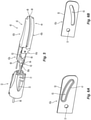
FIGS. 6A and 6B are side perspective views of a proximal flange portion of a first jaw member in accordance with aspects of the present disclosure; -
FIG. 7 is a side perspective view of the second jaw member ofFIG. 4 with a knife blade of the surgical instrument ofFIG. 1 ; -
FIG. 8A and 8B are perspective views of a knife assembly of the surgical instrument ofFIG. 1 ; -
FIG. 9A is a proximal end view of the second jaw member ofFIG. 4 ; -
FIG. 9B is a cross-sectional view of the second jaw member ofFIG. 9A , taken alongsection line 9B-9B ofFIG. 9A ; -
FIG. 10A is a rear perspective view of an internal spacer of the second jaw member ofFIG. 9A ; -
FIG. 10B is a rear perspective view of the second jaw member ofFIG. 9A , shown with an outer housing of the second jaw member removed; -
FIG. 11A is a side perspective view of an internal spacer of the first jaw member ofFIG. 3 ; -
FIG. 11B is a side perspective view of the first jaw member ofFIG. 3 , shown with an outer housing of the first jaw member removed; -
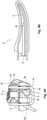
FIG. 12A is a side view of a first jaw member of the surgical instrument ofFIG. 1 in accordance with aspects of the present disclosure; -
FIG. 12B is a perspective view of first and second jaw members of the surgical instrument ofFIG. 1 in accordance with aspects of the present disclosure; and -
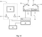
FIG. 13 is a schematic illustration of an exemplary robotic surgical system configured to releasably receive the surgical instrument ofFIG. 1 . - Referring to
FIGS. 1 and2 , asurgical instrument 10 provided in accordance with the present disclosure generally includes ahousing 20, ashaft 30 extending distally from thehousing 20, anend effector assembly 40 extending distally from theshaft 30, and anactuation assembly 100 disposed within thehousing 20 and operably associated with theshaft 30 and theend effector assembly 40. Thesurgical instrument 10 is detailed herein as an articulating electrosurgical forceps configured for use with a robotic surgical system, e.g., robotic surgical system 500 (FIG. 13 ). However, the aspects and features of thesurgical instrument 10 provided in accordance with the present disclosure, detailed below, are equally applicable for use with other suitable surgical instruments (including non-robotic surgical instrument) and/or in other suitable surgical systems (including non-robotic surgical systems). - The
housing 20 of thesurgical instrument 10 includes first andsecond body portions FIG. 2 ) that cooperate to enclose theactuation assembly 100 therein. Theproximal faceplate 24 includes apertures defined therein through whichinputs actuation assembly 100 extend. A pair of latch levers 26 (only one of which is illustrated inFIG. 1 ) extends outwardly from opposing sides of thehousing 20 and enables releasable engagement (directly or indirectly) of thehousing 20 with a robotic arm of a surgical system, e.g., robotic surgical system 500 (FIG. 13 ). Anaperture 28 defined through thehousing 20 permits athumbwheel 440 to extend therethrough to enable manual manipulation of thethumbwheel 440 from the exterior of thehousing 20 to permit manual opening and closing of theend effector assembly 40. - The
shaft 30 of thesurgical instrument 10 includes a distal segment 32 (such as, for example, a collar or clevis), a proximal segment 34, and an articulatingsection 36 disposed between the distal andproximal segments 32, 34, respectively. The articulatingsection 36 includes one or more articulatingcomponents 37, e.g., links, joints, etc. A plurality ofarticulation cables 38, e.g., four (4) articulation cables, or other suitable actuators, extends through the articulatingsection 36. More specifically, thearticulation cables 38 are operably coupled to thedistal segment 32 of theshaft 30 at the distal ends thereof and extend proximally from thedistal segment 32 of theshaft 30, through the articulatingsection 36 and the proximal segment 34 of theshaft 30, and into thehousing 20, wherein thearticulation cables 38 operably couple with anarticulation assembly 200 of theactuation assembly 100 to enable selective articulation of the distal segment 32 (and, thus the end effector assembly 40) relative to the proximal segment 34 and thehousing 20, e.g., about at least two axes of articulation (yaw and pitch articulation, for example). Thearticulation assembly 200 is operably coupled between the first andsecond inputs actuation assembly 100 and the articulation cables 38 (FIG. 1 ) such that, upon receipt of appropriate rotational inputs into the first and/orsecond inputs articulation assembly 200 manipulates thearticulation cables 38 to articulate theend effector assembly 40 in a desired direction, e.g., to pitch and/or yaw theend effector assembly 40. Thearticulation cables 38 are arranged in a generally rectangular configuration, although other suitable configurations are also contemplated. - With respect to articulation of the
end effector assembly 40 relative to the proximal segment 34 of theshaft 30, actuation of thearticulation cables 38 is effected in pairs. More specifically, in order to pitch theend effector assembly 40, the upper pair ofcables 38 is actuated in a similar manner while the lower pair ofcables 38 is actuated in a similar manner relative to one another but an opposite manner relative to the upper pair ofcables 38. With respect to yaw articulation, the right pair ofcables 38 is actuated in a similar manner while the left pair ofcables 38 is actuated in a similar manner relative to one another but an opposite manner relative to the right pair ofcables 38. - With reference to
FIGS. 3-5 , theend effector assembly 40 includes first andsecond jaw members second jaw members proximal flange portion distal body portion Proximal flange portions FIG. 1 ) and are operably coupled to one another via a cam-slot assembly 62 (FIG. 5 ). The cam-slot assembly 62 includes a cam pin 64 (FIG. 1 ) slidably received within cam slot(s) 63 defined within at least one of theproximal flange portions second jaw members first jaw member 42 relative to thesecond jaw member 44. Pivoting of thefirst jaw member 42 relative to thesecond jaw member 44 moves thedistal body portions surfaces second jaw members second jaw members distal segment 32 ofshaft 30. - As seen in
FIGS. 3 and 4 , theproximal flange portion 43a of thefirst jaw member 42 has a single plate-shapedflange 50 defining a pivot aperture 51 (FIG. 6A ) therethrough and an angled orcurved clam slot 63 extending through and along a length thereof. Theproximal flange portion 45a of thesecond jaw member 44 includes a pair of spaced-apart plate-shapedflanges pivot apertures proximal flange portions flange 50 of thefirst jaw member 42 is positionable between theflanges second jaw member 44 with thepivot aperture 51 of thefirst jaw member 42 aligned with thepivot apertures second jaw member 44. - The
pivot apertures second jaw member 44 are defined in a portion of theproximal flange portion 45a axially behind thedistal body portion 45b to minimize the dead space in thedistal segment 32 of theshaft 30 in which theproximal flange portions pivot apertures second jaw member 44 are disposed in a lower half of theproximal flange portion 45a directly behind thedistal body portion 45b, and thepivot aperture 51 of theproximal flange portion 43a of thefirst jaw member 42 is disposed in a position configured to align with thepivot apertures second jaw member 44 when received therebetween. The pivot pin 50 (FIG. 1 ) is inserted through thepivot apertures pivot aperture 31 defined through thedistal segment 32 of theshaft 30, to pivotably couple the first andsecond jaw member shaft 30 and to one another. - With continued reference to
FIG. 5 , the cam-slot assembly 62 includes acam bar 66 having adistal end portion 66a coupled to ablock 68, and acam pin 64 extending outwardly from opposing lateral sides of theblock 68. Theblock 68 defines anannular cutout 69 configured to receive the pivot pin 60 (FIG. 1 ) when thecam bar 66 is in a distal, deployed position. Theannular cutout 69, therefore, allows full distal translation of thecam bar 66 without interference from thepivot pin 60. A first end of thecam pin 64 is received in alinear cam slot 33 of thedistal segment 32 of theshaft 30 to guide and support a linear movement of thecam bar 66, and a second end of the cam pin 64 (not explicitly shown) is received in thecam slot 63 of theproximal flange portion 43a offirst jaw member 42. - The
cam slot 63 in theproximal flange portion 43a of thefirst jaw member 42 is shaped such that advancement (e.g., distal translation) of thecam bar 66 relative to theproximal flange portion 43a causes thecam pin 64 to ride distally through thecam slot 63 and drives a pivoting of thefirst jaw member 42 away from thesecond jaw member 44 to transition theend effector assembly 40 from the closed position to the open position. Similarly, retraction (e.g., proximal translation) of thecam bar 66 relative to theproximal flange portion 43a causes thecam pin 64 to ride proximally through thecam slot 63 and drives a pivoting of thefirst jaw member 42 towards thesecond jaw member 44 to transition theend effector assembly 40 from the open position to the closed position for grasping tissue between the tissue-contactingsurfaces cam bar 66 may be moved distally to transition theend effector assembly 40 to the closed position and proximally to transition theend effector assembly 40 to the open position. - The
cam bar 66 extends proximally from theend effector assembly 40 through theshaft assembly 30 and into thehousing 20 wherein thecam bar 66 is operably coupled with a jaw drive assembly 400 (FIG. 2 ) of theactuation assembly 100 to enable selective actuation of theend effector assembly 40. Thejaw drive assembly 400 is operably coupled between thefourth input 140 of theactuation assembly 100 and thecam bar 66 such that, upon receipt of appropriate rotational input into thefourth input 140, thejaw drive assembly 400 pivots the first andsecond jaw members - In aspects, as shown in
FIGS. 6A and 6B , theproximal flange portion 43a of thefirst jaw member 42 includes alip 41 extending around thecam slot 63. Thelip 41 extends tangentially outward from a side surface of theproximal flange portion 43a around the entirety of thecam slot 63 to increase cam slot strength and/or reduce clam slot stress, for example, if theproximal flange portion 43a has a thin-wall construction and/or the first andsecond jaw members lip 41, however, may have other configurations. For example, thelip 41 may be discontinuous and extend along opposed sides and/or ends of thecam slot 63, such as around a proximal end portion of thecam slot 63 coinciding with closing of the first andsecond jaw members 42, 44 (or a distal end portion of thecam slot 63 in aspects where thecam bar 66 is moved distally for closing of the first andsecond jaw members 42, 44). As another example, thelip 41 may extend outwardly from both side surfaces of theproximal flange portion 43a. - Turning again to
FIGS. 3 and 4 , thedistal body portions second jaw members surfaces tissue contacting surfaces tissue contacting surfaces FIG. 1 ) defines a conductive pathway (not shown) through thehousing 20 and theshaft 30 to theend effector assembly 40 that includeselectric lead wires tissue contacting surfaces second jaw members tissue contacting surfaces tissue contacting surfaces - The
tissue contacting surfaces knife channel 47 of thesecond jaw member 44 is explicitly seen inFIG. 4 ). As shown inFIGS. 7-8B , aknife assembly 80 is provided that includes aknife rod 82 and aknife blade 84 fixed to or otherwise coupled to a distal end of theknife rod 82. Theknife assembly 80 enables cutting of tissue grasped betweentissue contacting surfaces second jaw members ferrule 86 may be engaged about a distal end portion of theknife rod 82 and secured within aslot 83 defined within a proximal portion of theknife blade 84 to securely engage theknife rod 82 with theknife blade 84 such that actuation of theknife rod 82 reciprocates theknife blade 84 between the first andsecond jaw member tissue contacting surfaces knife rod 82 and theferrule 86 are offset relative to theknife blade 84 such that theknife rod 82 and theferrule 86 protrude farther (or completely) from one side of theknife blade 84 and less (or not at all) from the other side. - The
knife rod 82 extends from the housing 20 (FIG. 1 ) through theshaft 30 to theend effector assembly 40. Theknife rod 82 is operably coupled to a knife drive assembly 300 (FIG. 2 ) of theactuation assembly 100 for selective actuation of theknife assembly 80 to reciprocate theknife blade 84 through the first andsecond jaw members FIG. 2 ) is operably coupled between theknife rod 82 of theknife assembly 80 and thethird input 130 of theactuation assembly 100 such that, upon receipt of appropriate rotational input into thethird input 130, theknife drive assembly 300 manipulates theknife rod 82 to reciprocate theknife blade 84 between the first andsecond jaw members tissue contacting surfaces - Turning now to
FIG. 9A , thesecond jaw member 44 is shown. Thesecond jaw member 44, as noted above, includesproximal flange portion 45a anddistal body portion 45b. Thesecond jaw member 44, more specifically, includes astructural jaw 49a, aninternal spacer 49b (e.g., an insulative spacer), anouter housing 49c, and an electrically-conductive plate 49d defining thetissue contacting surface 48. It should be understood that thefirst jaw member 42 is configured similar to thesecond jaw member 44 and includes similar component parts (e.g., a structural jaw, an internal spacer, an outer housing, and an electrically-conductive plate). - The
structural jaw 49a provides structural support tosecond jaw member 44 and includes a distal portion that supports the components of thedistal body portion 45b of thesecond jaw member 44 thereon and a proximal portion that extends proximally from thedistal body portion 45b to form theproximal flange portion 45a of thesecond jaw member 44. The distal portion of thestructural jaw 49a, together with theinternal spacer 49b, theouter housing 49c, and the electrically-conductive plate 49d, form thedistal body portion 45b of thesecond jaw member 44. Theinternal spacer 49b is disposed on the distal portion of thestructural jaw 49a, the electrically-conductive plate 49d is disposed on theinternal spacer 49b, and theouter housing 49c is disposed about theinternal spacer 49b, the distal portion of thestructural jaw 49a, and a portion of the electrically-conductive plate 49d to secure these components to one another, e.g., via overmolding, although other configurations are also contemplated. - The
longitudinally extending channel 47 of thesecond jaw member 44 is formed by cooperating channel portions defined within the electrically-conductive plate 49d and theinternal spacer 49b. Theinternal spacer 49b further includes a partially-cylindrical cut-out 55 that communicates with thelongitudinally extending channel 47. The cut-out 55 has a generally D-shaped configuration and is open at the proximal end of thedistal body portion 45b of thesecond jaw member 44 to permit insertion of theknife blade 84, and theknife rod 82 and ferrule 86 (FIG. 8B ) therethrough. As shown inFIG. 9B , the cut-out 55 has a rampeddistal end 55a tapering laterally inwardly towards the longitudinal extendingchannel 47 for preventing tissue from entering the second jaw member 44 (e.g., pushing or ejecting tissue out of thelongitudinally extending channel 47 when theknife blade 84 is deployed). It should be understood that the cut-out 55 may have other shapes depending, for example, on the configuration of the knife assembly 80 (FIG. 8A ). - As shown in
FIGS. 10A and 10B , in conjunction withFIG. 9A , theinternal spacer 49b of thesecond jaw member 44 includes awing 90 extending from aside edge 57a thereof. Thewing 90 extends downwardly from theside edge 57a of atop surface 57b on which the electrically-conductive plate 49d is disposed such that thewing 90 is in spaced relation relative to aside surface 57c of theinternal spacer 49b. A gap "G1" defined between thewing 90 and theinternal spacer 49b is sized and shaped to accommodate thestructural jaw 49a therein to separate thestructural jaw 49a from the electrically-conductive plate 49d. Theelectrical lead wire 99a that electrically connects thetissue contacting surface 48 to the energy source (not shown) is attached to the portion of the electrically-conductive plate 49d extending over thewing 90. Thewing 90 extends from a portion of theinternal spacer 49b that covers and isolates the attachment location (e.g., a wire weld strip) of theelectrical lead wire 99a to the electrically-conductive plate 49d. - As shown in
FIGS. 11A and 11B , theinternal spacer 49b' of thefirst jaw member 42 similarly includes a wing 90' extending from aside edge 57a' thereof. The wing 90' extends downwardly from theside edge 57a' of atop surface 57b' on which an electrically-conductive plate 49d' is disposed such that the wing 90' is in spaced relation relative to aside surface 57c' of theinternal spacer 49b'. A gap "G2" defined between the wing 90' and theinternal spacer 49b' is sized and shaped to accommodate thestructural jaw 49a' therein to separate thestructural jaw 49a' from the electrically-conductive plate 49d'. Theelectrical lead wire 99b that electrically connects thetissue contacting surface 46 to the energy source (not shown) is attached to the portion of the electrically-conductive plate 49d' extending over the wing 90'. The wing 90' extends from a portion of theinternal spacer 49b' that covers and isolates the attachment location (e.g., a wire weld strip) of theelectrical lead wire 99b to the electrically-conductive plate 49d'. - As shown in
FIGS. 12A and 12B , thefirst jaw member 42 may further include aplate 92 extending over a gap "G" defined between thedistal segment 32 of theshaft 30 and thedistal body portion 43b of thefirst jaw member 42. Theplate 92 covers the gap "G" and thus, theproximal flange portions second jaw members knife blade 84, minimizing tissue build up that may otherwise occur in the gap "G" and reducing pinch point between the first andsecond jaw members plate 92 may be coupled to or integrally formed with theouter housing 49c of thefirst jaw member 42 e.g., via overmolding, although other configurations are also contemplated. - Turning now to
FIG. 13 , a roboticsurgical system 500 is configured for use in accordance with the present disclosure. Aspects and features of the roboticsurgical system 500 not germane to the understanding of the present disclosure are omitted to avoid obscuring the aspects and features of the present disclosure in unnecessary detail. - The robotic
surgical system 500 generally includes a plurality ofrobot arms control device 504; and anoperating console 505 coupled withcontrol device 504. The operatingconsole 505 may include adisplay device 506, which may be set up in particular to display three-dimensional images; andmanual input devices robot arms surgical system 500 may be configured for use on apatient 513 lying on a patient table 512 to be treated in a minimally invasive manner. The roboticsurgical system 500 may further include adatabase 514, in particular coupled to thecontrol device 504, in which are stored, for example, pre-operative data from thepatient 513 and/or anatomical atlases. - Each of the
robot arms FIG. 1 ), thus providing such functionality on a roboticsurgical system 500. - Specifically, the actuation assembly 100 (
FIG. 2 ) is configured to operably interface with the roboticsurgical system 500 when thesurgical instrument 10 is mounted on the roboticsurgical system 500 to enable robotic operation of theactuation assembly 100. That is, the roboticsurgical system 500 selectively provides rotational inputs toinputs actuation assembly 100 to articulate theend effector assembly 40, grasp tissue between the first andsecond jaw members second jaw members - The
robot arms control device 504. Thecontrol device 504, e.g., a computer, may be configured to activate the motors, in particular by means of a computer program, in such a way that therobot arms manual input devices control device 504 may also be configured in such a way that it regulates the movement of therobot arms - It will be understood that various modifications may be made to the aspects and features disclosed herein. Therefore, the above description should not be construed as limiting, but merely as exemplifications of various aspects and features. Those skilled in the art will envision other modifications within the scope and spirit of the claims appended hereto.
- The invention may be described by reference to the following numbered paragraphs: -
- 1. An end effector assembly of a surgical instrument, comprising:
- a first jaw member including:
- a first structural jaw;
- a first internal spacer disposed on the first structural jaw, the first internal spacer including a first wing extending from a side edge thereof in spaced relation relative to a side surface of the first internal spacer;
- a first electrically-conductive plate disposed on the first internal spacer, the first electrically-conductive plate having a first tissue contacting surface defining a first longitudinally extending knife channel therethrough; and
- a first outer housing disposed about the first internal spacer, a portion of the first structure jaw, and a portion of the first electrically-conductive plate; and
- a second jaw member pivotably coupled to the first jaw member.
- a first jaw member including:
- 2. The end effector assembly of
paragraph 1, further including a first electrical lead wire attached to a portion of the first electrically-conductive plate positioned over the first wing of the first internal spacer. - 3. The end effector assembly of
paragraph 1, wherein the second jaw member includes:- a second structural jaw;
- a second internal spacer disposed on the second structural jaw, the second internal spacer including a second wing extending from a side edge thereof in spaced relation relative to a side surface of the second internal spacer;
- a second electrically-conductive plate disposed on the second internal spacer, the second electrically-conductive plate having a second tissue contacting surface defining a second longitudinally extending knife channel therethrough; and
- a second outer housing disposed about the second internal spacer, a portion of the second structure jaw, and a portion of the second electrically-conductive plate.
- 4. The end effector assembly of
paragraph 3, further including a second electrical lead wire attached to a portion of the second electrically-conductive plate positioned over the second wing of the second internal spacer. - 5. The end effector assembly of
paragraph 3, wherein the second internal spacer includes a partially-cylindrical cut-out in communication with the second longitudinally extending knife channel defined through the second electrically-conductive plate. - 6. The end effector assembly of paragraph 5, wherein the partially-cylindrical cut-out has a generally D-shaped configuration and is open at a proximal end of the second internal spacer to permit insertion of a knife blade and a knife rod therethrough.
- 7. The end effector assembly of
paragraph 3, wherein a distal portion of the first structural jaw, the first internal spacer, the first outer housing, and the first electrically-conductive plate form a distal body portion of the first jaw member, and a proximal portion of the first structural jaw forms a proximal flange portion of the first jaw member. - 8. The end effector assembly of paragraph 7, wherein a distal portion of the second structural jaw, the second internal spacer, the second outer housing, and the second electrically-conductive plate form a distal body portion of the second jaw member, and a proximal portion of the second structural jaw forms a proximal flange portion of the second jaw member.
- 9. The end effector assembly of paragraph 8, wherein the proximal flange portions of the first and second jaw members are pivotably coupled to one another about a pivot pin.
- 10. The end effector assembly of paragraph 9, wherein each of the proximal flange portions includes at least one pivot aperture disposed axially behind the distal body portion of the second jaw member, the pivot apertures aligned for receiving the pivot pin therethrough.
- 11. The end effector assembly of
paragraph 10, wherein the proximal flange portion of the first jaw member includes a single flange defining a pivot aperture therethrough, and the proximal flange portion of the second jaw member includes a pair of spaced-apart flanges defining aligned pivot apertures therethrough, the single flange of the first jaw member disposed between the pair of spaced-apart flanges of the second jaw member. - 12. The end effector assembly of paragraph 7, wherein the proximal flange portion of the first jaw member further includes a cam slot defined therethrough, the cam slot configured to slidably receive a cam pin.
- 13. The end effector assembly of paragraph 12, wherein the proximal flange portion of the first jaw member includes a lip extending around the cam slot.
- 14. The end effector assembly of paragraph 13, wherein the lip extends tangentially outward from a side surface of a plate-shaped flange of the proximal flange portion.
- 15. A surgical instrument, comprising:
- an end effector assembly including:
- a first jaw member including:
- a first structural jaw;
- a first internal spacer disposed on the first structural jaw, the first internal spacer including a first wing extending from a side edge thereof in spaced relation relative to a side surface of the first internal spacer;
- a first electrically-conductive plate disposed on the first internal spacer, the first electrically-conductive plate having a first tissue contacting surface defining a first longitudinally extending knife channel therethrough; and
- a first outer housing disposed about the first internal spacer, a portion of the first structure jaw, and a portion of the first electrically-conductive plate; and
- a second jaw member pivotably coupled to the first jaw member; and
- a first jaw member including:
- a shaft extending proximally from the end effector assembly, the shaft including a distal segment within which proximal flange portions of the end effector assembly are disposed, the first and second jaw members pivotably coupled to one another and the distal segment of the shaft via a pivot pin extending through the proximal flange portions and the distal segment.
- an end effector assembly including:
- 16. The surgical instrument of paragraph 15, wherein the first outer housing of the first jaw member includes a plate extending over a portion of the proximal flange portions of the first and second jaw members.
- 17. The surgical instrument of paragraph 15, further including a housing extending proximally from the shaft, the housing including an actuation assembly operably associated with the shaft and the end effector assembly.
- 18. The surgical instrument of paragraph 17, further including a cam-slot assembly including a cam slot defined in the proximal flange portion of at least one of the first or second jaw members, a cam pin slidably received within the cam slot, and a cam bar coupled to the cam pin, the cam bar extending from the housing, through the shaft, and into the end effector assembly.
- 19. The surgical instrument of paragraph 17, further including a knife assembly including a knife blade coupled to a distal end of a knife rod, the knife rod extending from the housing, through the shaft, and into the end effector assembly.
- 20. The surgical instrument of paragraph 17, wherein the actuation assembly includes a plurality of inputs configured to operably interface with a robotic surgical system.
Claims (15)
- An end effector assembly of a surgical instrument, comprising:a first jaw member including:a first structural jaw;a first internal spacer disposed on the first structural jaw, the first internal spacer including a first wing extending from a side edge thereof in spaced relation relative to a side surface of the first internal spacer;a first electrically-conductive plate disposed on the first internal spacer, the first electrically-conductive plate having a first tissue contacting surface defining a first longitudinally extending knife channel therethrough; anda first outer housing disposed about the first internal spacer, a portion of the first structure jaw, and a portion of the first electrically-conductive plate; anda second jaw member pivotably coupled to the first jaw member.
- The end effector assembly of claim 1, further including a first electrical lead wire attached to a portion of the first electrically-conductive plate positioned over the first wing of the first internal spacer.
- The end effector assembly of claim 1 or 2, wherein the second jaw member includes:a second structural jaw;a second internal spacer disposed on the second structural jaw, the second internal spacer including a second wing extending from a side edge thereof in spaced relation relative to a side surface of the second internal spacer;a second electrically-conductive plate disposed on the second internal spacer, the second electrically-conductive plate having a second tissue contacting surface defining a second longitudinally extending knife channel therethrough; anda second outer housing disposed about the second internal spacer, a portion of the second structure jaw, and a portion of the second electrically-conductive plate.
- The end effector assembly of claim 3, further including a second electrical lead wire attached to a portion of the second electrically-conductive plate positioned over the second wing of the second internal spacer.
- The end effector assembly of claim 3, wherein the second internal spacer includes a partially-cylindrical cut-out in communication with the second longitudinally extending knife channel defined through the second electrically-conductive plate.
- The end effector assembly of claim 5, wherein the partially-cylindrical cut-out has a generally D-shaped configuration and is open at a proximal end of the second internal spacer to permit insertion of a knife blade and a knife rod therethrough.
- The end effector assembly of claim 3, wherein a distal portion of the first structural jaw, the first internal spacer, the first outer housing, and the first electrically-conductive plate form a distal body portion of the first jaw member, and a proximal portion of the first structural jaw forms a proximal flange portion of the first jaw member.
- The end effector assembly of claim 7, wherein a distal portion of the second structural jaw, the second internal spacer, the second outer housing, and the second electrically-conductive plate form a distal body portion of the second jaw member, and a proximal portion of the second structural jaw forms a proximal flange portion of the second jaw member.
- The end effector assembly of claim 8, wherein the proximal flange portions of the first and second jaw members are pivotably coupled to one another about a pivot pin.
- The end effector assembly of claim 9, wherein each of the proximal flange portions includes at least one pivot aperture disposed axially behind the distal body portion of the second jaw member, the pivot apertures aligned for receiving the pivot pin therethrough.
- The end effector assembly of claim 10, wherein the proximal flange portion of the first jaw member includes a single flange defining a pivot aperture therethrough, and the proximal flange portion of the second jaw member includes a pair of spaced-apart flanges defining aligned pivot apertures therethrough, the single flange of the first jaw member disposed between the pair of spaced-apart flanges of the second jaw member.
- The end effector assembly of claim 7, wherein the proximal flange portion of the first jaw member further includes a cam slot defined therethrough, the cam slot configured to slidably receive a cam pin.
- The end effector assembly of claim 12, wherein the proximal flange portion of the first jaw member includes a lip extending around the cam slot.
- The end effector assembly of claim 13, wherein the lip extends tangentially outward from a side surface of a plate-shaped flange of the proximal flange portion.
- A surgical instrument, comprising:an end effector assembly as claimed in any one of claims 1 to 14 including:a first jaw member including:a first structural jaw;a first internal spacer disposed on the first structural jaw, the first internal spacer including a first wing extending from a side edge thereof in spaced relation relative to a side surface of the first internal spacer;a first electrically-conductive plate disposed on the first internal spacer, the first electrically-conductive plate having a first tissue contacting surface defining a first longitudinally extending knife channel therethrough; anda first outer housing disposed about the first internal spacer, a portion of the first structure jaw, and a portion of the first electrically-conductive plate; anda second jaw member pivotably coupled to the first jaw member; anda shaft extending proximally from the end effector assembly, the shaft including a distal segment within which proximal flange portions of the end effector assembly are disposed, the first and second jaw members pivotably coupled to one another and the distal segment of the shaft via a pivot pin extending through the proximal flange portions and the distal segment.
Applications Claiming Priority (1)
| Application Number | Priority Date | Filing Date | Title |
|---|---|---|---|
| US17/020,117 US11925406B2 (en) | 2020-09-14 | 2020-09-14 | End effector assemblies for surgical instruments |
Publications (3)
| Publication Number | Publication Date |
|---|---|
| EP3967256A1 true EP3967256A1 (en) | 2022-03-16 |
| EP3967256B1 EP3967256B1 (en) | 2025-10-29 |
| EP3967256B8 EP3967256B8 (en) | 2025-12-10 |
Family
ID=77774712
Family Applications (1)
| Application Number | Title | Priority Date | Filing Date |
|---|---|---|---|
| EP21196716.1A Active EP3967256B8 (en) | 2020-09-14 | 2021-09-14 | End effector assemblies for surgical instruments |
Country Status (3)
| Country | Link |
|---|---|
| US (1) | US11925406B2 (en) |
| EP (1) | EP3967256B8 (en) |
| CN (1) | CN114176780B (en) |
Citations (4)
| Publication number | Priority date | Publication date | Assignee | Title |
|---|---|---|---|---|
| US20120215220A1 (en) * | 2011-02-18 | 2012-08-23 | Intuitive Surgical Operations, Inc. | Fusing and cutting surgical instrument and related methods |
| US20140025071A1 (en) * | 2012-05-01 | 2014-01-23 | Covidien Lp | Simplified spring load mechanism for delivering shaft force of a surgical instrument |
| US20180206907A1 (en) * | 2001-04-06 | 2018-07-26 | Covidien Ag | Vessel sealer and divider |
| US20190015124A1 (en) * | 2017-07-11 | 2019-01-17 | Conmed Corporation | Jaw assembly for a vessel sealer |
Family Cites Families (253)
| Publication number | Priority date | Publication date | Assignee | Title |
|---|---|---|---|---|
| US702472A (en) | 1898-08-08 | 1902-06-17 | Louis M Pignolet | Surgical forceps. |
| US2801633A (en) | 1954-02-17 | 1957-08-06 | Joseph C Ehrlich | Lancets |
| USD249549S (en) | 1976-10-22 | 1978-09-19 | Aspen Laboratories, Inc. | Electrosurgical handle |
| USD263020S (en) | 1980-01-22 | 1982-02-16 | Rau Iii David M | Retractable knife |
| US4478218A (en) * | 1982-02-26 | 1984-10-23 | Ethicon, Inc. | Ligating clip and applier instrument therefor with clip engaging escapement |
| USD299413S (en) | 1985-07-17 | 1989-01-17 | The Stanley Works | Folding pocket saw handle |
| USD295893S (en) | 1985-09-25 | 1988-05-24 | Acme United Corporation | Disposable surgical clamp |
| USD295894S (en) | 1985-09-26 | 1988-05-24 | Acme United Corporation | Disposable surgical scissors |
| USD298353S (en) | 1986-05-06 | 1988-11-01 | Vitalmetrics, Inc. | Handle for surgical instrument |
| US4793218A (en) | 1987-10-09 | 1988-12-27 | George Jordan | Method of forming knife blades by photo-chemical etching |
| US5486185A (en) | 1989-01-30 | 1996-01-23 | Dexide, Inc. | Surgical apparatus |
| CA2050868C (en) | 1990-10-05 | 2002-01-01 | Ernie Aranyi | Endoscopic surgical instrument |
| US5486189A (en) | 1990-10-05 | 1996-01-23 | United States Surgical Corporation | Endoscopic surgical instrument |
| US5626609A (en) | 1990-10-05 | 1997-05-06 | United States Surgical Corporation | Endoscopic surgical instrument |
| US5100506A (en) | 1990-12-04 | 1992-03-31 | Grace Manufacturing Inc. | Chemically machined sheet metal cutting tools and method |
| US5409453A (en) | 1992-08-12 | 1995-04-25 | Vidamed, Inc. | Steerable medical probe with stylets |
| USD348930S (en) | 1991-10-11 | 1994-07-19 | Ethicon, Inc. | Endoscopic stapler |
| US5242456A (en) | 1991-11-21 | 1993-09-07 | Kensey Nash Corporation | Apparatus and methods for clamping tissue and reflecting the same |
| US5317938A (en) | 1992-01-16 | 1994-06-07 | Duke University | Method for making microstructural surgical instruments |
| US5383471A (en) | 1992-04-10 | 1995-01-24 | Funnell; David M. | Surgical biopsy instrument |
| US5431667A (en) | 1992-05-26 | 1995-07-11 | Origin Medsystems, Inc. | Gas-sealed instruments for use in laparoscopic surgery |
| USD349341S (en) | 1992-10-28 | 1994-08-02 | Microsurge, Inc. | Endoscopic grasper |
| US5395364A (en) | 1993-06-10 | 1995-03-07 | Symbiosis Corporation | Endoscopic instrument incorporating an elastomeric fluid seal |
| US5302234A (en) | 1993-01-28 | 1994-04-12 | Grace Manufacturing Inc. | Surgical cutting instrument forming method |
| US5620447A (en) | 1993-01-29 | 1997-04-15 | Smith & Nephew Dyonics Inc. | Surgical instrument |
| US5833692A (en) | 1993-01-29 | 1998-11-10 | Smith & Nephew, Inc. | Surgical instrument |
| USD343453S (en) | 1993-05-05 | 1994-01-18 | Laparomed Corporation | Handle for laparoscopic surgical instrument |
| USD354564S (en) | 1993-06-25 | 1995-01-17 | Richard-Allan Medical Industries, Inc. | Surgical clip applier |
| US5477604A (en) | 1993-11-01 | 1995-12-26 | Smith; Daniel | Process for manufacturing taper point surgical needles |
| USD358887S (en) | 1993-12-02 | 1995-05-30 | Cobot Medical Corporation | Combined cutting and coagulating forceps |
| US5522839A (en) | 1994-09-09 | 1996-06-04 | Pilling Weck Incorporated | Dissecting forceps |
| USD384413S (en) | 1994-10-07 | 1997-09-30 | United States Surgical Corporation | Endoscopic suturing instrument |
| US5752973A (en) | 1994-10-18 | 1998-05-19 | Archimedes Surgical, Inc. | Endoscopic surgical gripping instrument with universal joint jaw coupler |
| US5571129A (en) | 1995-05-15 | 1996-11-05 | Portlyn Corporation | Surgical cutting instrument with improved cleaning capability and ease of use |
| USH1745H (en) | 1995-09-29 | 1998-08-04 | Paraschac; Joseph F. | Electrosurgical clamping device with insulation limited bipolar electrode |
| US5707392A (en) | 1995-09-29 | 1998-01-13 | Symbiosis Corporation | Hermaphroditic stamped forceps jaw for disposable endoscopic biopsy forceps and method of making the same |
| US5716374A (en) | 1995-10-10 | 1998-02-10 | Symbiosis Corporation | Stamped clevis for endoscopic instruments and method of making the same |
| USD408018S (en) | 1996-03-12 | 1999-04-13 | Mcnaughton Patrick J | Switch guard |
| USD416089S (en) | 1996-04-08 | 1999-11-02 | Richard-Allan Medical Industries, Inc. | Endoscopic linear stapling and dividing surgical instrument |
| US5792135A (en) | 1996-05-20 | 1998-08-11 | Intuitive Surgical, Inc. | Articulated surgical instrument for performing minimally invasive surgery with enhanced dexterity and sensitivity |
| US7666191B2 (en) | 1996-12-12 | 2010-02-23 | Intuitive Surgical, Inc. | Robotic surgical system with sterile surgical adaptor |
| USH2037H1 (en) | 1997-05-14 | 2002-07-02 | David C. Yates | Electrosurgical hemostatic device including an anvil |
| USH1904H (en) | 1997-05-14 | 2000-10-03 | Ethicon Endo-Surgery, Inc. | Electrosurgical hemostatic method and device |
| US6096037A (en) | 1997-07-29 | 2000-08-01 | Medtronic, Inc. | Tissue sealing electrosurgery device and methods of sealing tissue |
| USD402028S (en) | 1997-10-10 | 1998-12-01 | Invasatec, Inc. | Hand controller for medical system |
| US7758569B2 (en) | 1998-02-24 | 2010-07-20 | Hansen Medical, Inc. | Interchangeable surgical instrument |
| US6277117B1 (en) | 1998-10-23 | 2001-08-21 | Sherwood Services Ag | Open vessel sealing forceps with disposable electrodes |
| US7267677B2 (en) | 1998-10-23 | 2007-09-11 | Sherwood Services Ag | Vessel sealing instrument |
| USD425201S (en) | 1998-10-23 | 2000-05-16 | Sherwood Services Ag | Disposable electrode assembly |
| USD424694S (en) | 1998-10-23 | 2000-05-09 | Sherwood Services Ag | Forceps |
| USD449886S1 (en) | 1998-10-23 | 2001-10-30 | Sherwood Services Ag | Forceps with disposable electrode |
| US6202465B1 (en) | 1999-03-05 | 2001-03-20 | Micro Stamping Corporation | Method for forming endoscopic instrument body |
| US6013028A (en) | 1999-04-23 | 2000-01-11 | Integra Neurocare Llc | Tissue spreading instrument for use in narrow passage |
| US6117158A (en) | 1999-07-07 | 2000-09-12 | Ethicon Endo-Surgery, Inc. | Ratchet release mechanism for hand held instruments |
| US6419675B1 (en) | 1999-09-03 | 2002-07-16 | Conmed Corporation | Electrosurgical coagulating and cutting instrument |
| US6423051B1 (en) | 1999-09-16 | 2002-07-23 | Aaron V. Kaplan | Methods and apparatus for pericardial access |
| USD465281S1 (en) | 1999-09-21 | 2002-11-05 | Karl Storz Gmbh & Co. Kg | Endoscopic medical instrument |
| US7048744B2 (en) | 2001-04-26 | 2006-05-23 | Sol Wiess | Attachable surgical accessory instrument |
| USD453923S1 (en) | 2000-11-16 | 2002-02-26 | Carling Technologies, Inc. | Electrical rocker switch guard |
| US6554829B2 (en) | 2001-01-24 | 2003-04-29 | Ethicon, Inc. | Electrosurgical instrument with minimally invasive jaws |
| USD454951S1 (en) | 2001-02-27 | 2002-03-26 | Visionary Biomedical, Inc. | Steerable catheter |
| USD466209S1 (en) | 2001-02-27 | 2002-11-26 | Visionary Biomedical, Inc. | Steerable catheter |
| AU2002250551B2 (en) | 2001-04-06 | 2006-02-02 | Covidien Ag | Molded insulating hinge for bipolar instruments |
| USD457959S1 (en) | 2001-04-06 | 2002-05-28 | Sherwood Services Ag | Vessel sealer |
| USD457958S1 (en) | 2001-04-06 | 2002-05-28 | Sherwood Services Ag | Vessel sealer and divider |
| AU2001249933B2 (en) | 2001-04-06 | 2006-06-08 | Covidien Ag | Vessel sealer and divider with non-conductive stop members |
| US7101371B2 (en) | 2001-04-06 | 2006-09-05 | Dycus Sean T | Vessel sealer and divider |
| US6817974B2 (en) | 2001-06-29 | 2004-11-16 | Intuitive Surgical, Inc. | Surgical tool having positively positionable tendon-actuated multi-disk wrist joint |
| US6994709B2 (en) | 2001-08-30 | 2006-02-07 | Olympus Corporation | Treatment device for tissue from living tissues |
| DE10156313A1 (en) | 2001-11-19 | 2003-06-05 | Wolf Gmbh Richard | Medical forceps |
| US7367939B2 (en) | 2004-06-14 | 2008-05-06 | Ethicon Endo-Surgery, Inc. | Rotational, translational and torqueing control members for an endoscopic instrument |
| US6602252B2 (en) | 2002-01-03 | 2003-08-05 | Starion Instruments Corporation | Combined dissecting, cauterizing, and stapling device |
| US6969385B2 (en) | 2002-05-01 | 2005-11-29 | Manuel Ricardo Moreyra | Wrist with decoupled motion transmission |
| US7270664B2 (en) | 2002-10-04 | 2007-09-18 | Sherwood Services Ag | Vessel sealing instrument with electrical cutting mechanism |
| US20040148992A1 (en) | 2003-01-30 | 2004-08-05 | Huang Yih Ren | Rolled tube fabrication method |
| USD493888S1 (en) | 2003-02-04 | 2004-08-03 | Sherwood Services Ag | Electrosurgical pencil with pistol grip |
| USD496997S1 (en) | 2003-05-15 | 2004-10-05 | Sherwood Services Ag | Vessel sealer and divider |
| USD499181S1 (en) | 2003-05-15 | 2004-11-30 | Sherwood Services Ag | Handle for a vessel sealer and divider |
| USD502994S1 (en) | 2003-05-21 | 2005-03-15 | Blake, Iii Joseph W | Repeating multi-clip applier |
| US7156846B2 (en) | 2003-06-13 | 2007-01-02 | Sherwood Services Ag | Vessel sealer and divider for use with small trocars and cannulas |
| USD545432S1 (en) | 2003-08-08 | 2007-06-26 | Olympus Corporation | Distal portion of hemostatic forceps for endoscope |
| USD509297S1 (en) | 2003-10-17 | 2005-09-06 | Tyco Healthcare Group, Lp | Surgical instrument |
| WO2005049097A2 (en) | 2003-11-13 | 2005-06-02 | Jerome Canady | Bipolar surgical forceps with argon plasma coagulation capability |
| USD541938S1 (en) | 2004-04-09 | 2007-05-01 | Sherwood Services Ag | Open vessel sealer with mechanical cutter |
| US8231652B2 (en) | 2004-04-26 | 2012-07-31 | Boston Scientific Scimed, Inc. | Instrument with sealing device and methods of advancing fluid therethrough |
| USD533942S1 (en) | 2004-06-30 | 2006-12-19 | Sherwood Services Ag | Open vessel sealer with mechanical cutter |
| US7857183B2 (en) | 2004-07-28 | 2010-12-28 | Ethicon Endo-Surgery, Inc. | Surgical instrument incorporating an electrically actuated articulation mechanism |
| US7143925B2 (en) | 2004-07-28 | 2006-12-05 | Ethicon Endo-Surgery, Inc. | Surgical instrument incorporating EAP blocking lockout mechanism |
| US7195631B2 (en) | 2004-09-09 | 2007-03-27 | Sherwood Services Ag | Forceps with spring loaded end effector assembly |
| US7540872B2 (en) | 2004-09-21 | 2009-06-02 | Covidien Ag | Articulating bipolar electrosurgical instrument |
| USD541418S1 (en) | 2004-10-06 | 2007-04-24 | Sherwood Services Ag | Lung sealing device |
| USD531311S1 (en) | 2004-10-06 | 2006-10-31 | Sherwood Services Ag | Pistol grip style elongated dissecting and dividing instrument |
| USD525361S1 (en) | 2004-10-06 | 2006-07-18 | Sherwood Services Ag | Hemostat style elongated dissecting and dividing instrument |
| USD535027S1 (en) | 2004-10-06 | 2007-01-09 | Sherwood Services Ag | Low profile vessel sealing and cutting mechanism |
| USD567943S1 (en) | 2004-10-08 | 2008-04-29 | Sherwood Services Ag | Over-ratchet safety for a vessel sealing instrument |
| USD533274S1 (en) | 2004-10-12 | 2006-12-05 | Allegiance Corporation | Handle for surgical suction-irrigation device |
| USD582038S1 (en) | 2004-10-13 | 2008-12-02 | Medtronic, Inc. | Transurethral needle ablation device |
| USD564662S1 (en) | 2004-10-13 | 2008-03-18 | Sherwood Services Ag | Hourglass-shaped knife for electrosurgical forceps |
| JP4864886B2 (en) | 2005-03-31 | 2012-02-01 | Thk株式会社 | Thrust transmission device |
| USD538932S1 (en) | 2005-06-30 | 2007-03-20 | Medical Action Industries Inc. | Surgical needle holder |
| US8579176B2 (en) | 2005-07-26 | 2013-11-12 | Ethicon Endo-Surgery, Inc. | Surgical stapling and cutting device and method for using the device |
| US20080264139A1 (en) | 2005-09-15 | 2008-10-30 | Rosenbohm Ronald A | Method and Apparatus for Manufacturing Precision Parts |
| US8241282B2 (en) | 2006-01-24 | 2012-08-14 | Tyco Healthcare Group Lp | Vessel sealing cutting assemblies |
| US8298232B2 (en) | 2006-01-24 | 2012-10-30 | Tyco Healthcare Group Lp | Endoscopic vessel sealer and divider for large tissue structures |
| USD541611S1 (en) | 2006-01-26 | 2007-05-01 | Robert Bosch Gmbh | Cordless screwdriver |
| US8029531B2 (en) | 2006-07-11 | 2011-10-04 | Cambridge Endoscopic Devices, Inc. | Surgical instrument |
| USD547154S1 (en) | 2006-09-08 | 2007-07-24 | Winsource Industries Limited | Rotary driving tool |
| EP2083728A4 (en) | 2006-10-05 | 2014-10-08 | Covidien Lp | Flexible endoscopic stitching devices |
| US8028395B2 (en) | 2006-10-06 | 2011-10-04 | Applied Medical Resources Corporation | Method for manufacturing high flow insufflation needle stylet |
| USD575395S1 (en) | 2007-02-15 | 2008-08-19 | Tyco Healthcare Group Lp | Hemostat style elongated dissecting and dividing instrument |
| USD649249S1 (en) | 2007-02-15 | 2011-11-22 | Tyco Healthcare Group Lp | End effectors of an elongated dissecting and dividing instrument |
| USD575401S1 (en) | 2007-06-12 | 2008-08-19 | Tyco Healthcare Group Lp | Vessel sealer |
| US20080319467A1 (en) | 2007-06-22 | 2008-12-25 | Thomas Wenchell | Thin bladed obturator |
| EP2197364B1 (en) | 2007-09-21 | 2016-07-20 | Covidien LP | Surgical device |
| US20090088743A1 (en) | 2007-09-28 | 2009-04-02 | Shinya Masuda | Surgical operating apparatus |
| AU2008221509B2 (en) | 2007-09-28 | 2013-10-10 | Covidien Lp | Dual durometer insulating boot for electrosurgical forceps |
| US8192444B2 (en) | 2008-01-16 | 2012-06-05 | Tyco Healthcare Group Lp | Uterine sealer |
| US7861906B2 (en) | 2008-02-14 | 2011-01-04 | Ethicon Endo-Surgery, Inc. | Surgical stapling apparatus with articulatable components |
| US20100069903A1 (en) | 2008-09-18 | 2010-03-18 | Tyco Healthcare Group Lp | Vessel Sealing Instrument With Cutting Mechanism |
| US8636761B2 (en) | 2008-10-09 | 2014-01-28 | Covidien Lp | Apparatus, system, and method for performing an endoscopic electrosurgical procedure |
| US8197479B2 (en) | 2008-12-10 | 2012-06-12 | Tyco Healthcare Group Lp | Vessel sealer and divider |
| US8858547B2 (en) | 2009-03-05 | 2014-10-14 | Intuitive Surgical Operations, Inc. | Cut and seal instrument |
| USD621503S1 (en) | 2009-04-28 | 2010-08-10 | Tyco Healthcare Group Ip | Pistol grip laparoscopic sealing and dissection device |
| US8187273B2 (en) | 2009-05-07 | 2012-05-29 | Tyco Healthcare Group Lp | Apparatus, system, and method for performing an electrosurgical procedure |
| USD617902S1 (en) | 2009-05-13 | 2010-06-15 | Tyco Healthcare Group Lp | End effector tip with undercut top jaw |
| USD618798S1 (en) | 2009-05-13 | 2010-06-29 | Tyco Healthcare Group Lp | Vessel sealing jaw seal plate |
| USD617903S1 (en) | 2009-05-13 | 2010-06-15 | Tyco Healthcare Group Lp | End effector pointed tip |
| USD649643S1 (en) | 2009-05-13 | 2011-11-29 | Tyco Healthcare Group Lp | End effector with a rounded tip |
| USD617900S1 (en) | 2009-05-13 | 2010-06-15 | Tyco Healthcare Group Lp | End effector tip with undercut bottom jaw |
| USD617901S1 (en) | 2009-05-13 | 2010-06-15 | Tyco Healthcare Group Lp | End effector chamfered tip |
| US8246618B2 (en) | 2009-07-08 | 2012-08-21 | Tyco Healthcare Group Lp | Electrosurgical jaws with offset knife |
| USD630324S1 (en) | 2009-08-05 | 2011-01-04 | Tyco Healthcare Group Lp | Dissecting surgical jaw |
| US8430876B2 (en) | 2009-08-27 | 2013-04-30 | Tyco Healthcare Group Lp | Vessel sealer and divider with knife lockout |
| USD627462S1 (en) | 2009-09-09 | 2010-11-16 | Tyco Healthcare Group Lp | Knife channel of a jaw device |
| KR101847990B1 (en) | 2009-11-13 | 2018-04-11 | 인튜어티브 서지컬 오퍼레이션즈 인코포레이티드 | Surgical tool with a compact wrist |
| EP2498710B1 (en) | 2009-11-13 | 2018-05-16 | Intuitive Surgical Operations, Inc. | Motor interface for parallel drive shafts within an independently rotating member |
| US9259275B2 (en) | 2009-11-13 | 2016-02-16 | Intuitive Surgical Operations, Inc. | Wrist articulation by linked tension members |
| USD628289S1 (en) | 2009-11-30 | 2010-11-30 | Tyco Healthcare Group Lp | Surgical instrument handle |
| USD628290S1 (en) | 2009-11-30 | 2010-11-30 | Tyco Healthcare Group Lp | Surgical instrument handle |
| US8545486B2 (en) | 2009-12-15 | 2013-10-01 | Covidien Lp | Surgical clip applier |
| US8540749B2 (en) | 2010-06-02 | 2013-09-24 | Covidien Lp | Apparatus for performing an electrosurgical procedure |
| US9192431B2 (en) | 2010-07-23 | 2015-11-24 | Ethicon Endo-Surgery, Inc. | Electrosurgical cutting and sealing instrument |
| USD661394S1 (en) | 2011-02-24 | 2012-06-05 | Tyco Healthcare Group Lp | Device jaw |
| US20120239034A1 (en) | 2011-03-17 | 2012-09-20 | Tyco Healthcare Group Lp | Method of Manufacturing Tissue Seal Plates |
| US8968305B2 (en) | 2011-03-28 | 2015-03-03 | Covidien Lp | Surgical forceps with external cutter |
| US9381059B2 (en) | 2011-04-05 | 2016-07-05 | Covidien Lp | Electrically-insulative hinge for electrosurgical jaw assembly, bipolar forceps including same, and methods of jaw-assembly alignment using fastened electrically-insulative hinge |
| US20120265241A1 (en) | 2011-04-12 | 2012-10-18 | Tyco Healthcare Group Lp | Surgical Forceps and Method of Manufacturing Thereof |
| US8568408B2 (en) | 2011-04-21 | 2013-10-29 | Covidien Lp | Surgical forceps |
| US8939972B2 (en) | 2011-05-06 | 2015-01-27 | Covidien Lp | Surgical forceps |
| US8900232B2 (en) | 2011-05-06 | 2014-12-02 | Covidien Lp | Bifurcated shaft for surgical instrument |
| US9113933B2 (en) | 2011-05-16 | 2015-08-25 | Covidien Lp | Optical energy-based methods and apparatus for tissue sealing |
| US10117705B2 (en) | 2011-05-16 | 2018-11-06 | Covidien Lp | Optical recognition of tissue and vessels |
| US9113934B2 (en) | 2011-05-16 | 2015-08-25 | Covidien Lp | Optical energy-based methods and apparatus for tissue sealing |
| US20120296238A1 (en) | 2011-05-16 | 2012-11-22 | Tyco Healthcare Group Lp | System and Methods for Energy-Based Sealing of Tissue with Optical Feedback |
| US8685009B2 (en) | 2011-05-16 | 2014-04-01 | Covidien Lp | Thread-like knife for tissue cutting |
| US9456870B2 (en) | 2011-05-16 | 2016-10-04 | Covidien Lp | Optical energy-based methods and apparatus for tissue sealing |
| US9265568B2 (en) | 2011-05-16 | 2016-02-23 | Coviden Lp | Destruction of vessel walls for energy-based vessel sealing enhancement |
| US20120296371A1 (en) | 2011-05-17 | 2012-11-22 | Tyco Healthcare Group Lp | Modular Shaft for Endoscopic Vessel Sealer and Divider |
| US8852185B2 (en) | 2011-05-19 | 2014-10-07 | Covidien Lp | Apparatus for performing an electrosurgical procedure |
| US8968283B2 (en) | 2011-05-19 | 2015-03-03 | Covidien Lp | Ultrasound device for precise tissue sealing and blade-less cutting |
| US9161807B2 (en) | 2011-05-23 | 2015-10-20 | Covidien Lp | Apparatus for performing an electrosurgical procedure |
| US8702749B2 (en) | 2011-06-09 | 2014-04-22 | Covidien Lp | Lever latch assemblies for vessel sealer and divider |
| US9615877B2 (en) | 2011-06-17 | 2017-04-11 | Covidien Lp | Tissue sealing forceps |
| US20120330308A1 (en) | 2011-06-22 | 2012-12-27 | Tyco Healthcare Group Lp | Forceps |
| US9039704B2 (en) | 2011-06-22 | 2015-05-26 | Covidien Lp | Forceps |
| US9844384B2 (en) | 2011-07-11 | 2017-12-19 | Covidien Lp | Stand alone energy-based tissue clips |
| US9039732B2 (en) | 2011-07-11 | 2015-05-26 | Covidien Lp | Surgical forceps |
| US8628557B2 (en) | 2011-07-11 | 2014-01-14 | Covidien Lp | Surgical forceps |
| US8745840B2 (en) | 2011-07-11 | 2014-06-10 | Covidien Lp | Surgical forceps and method of manufacturing thereof |
| US8888771B2 (en) | 2011-07-15 | 2014-11-18 | Covidien Lp | Clip-over disposable assembly for use with hemostat-style surgical instrument and methods of manufacturing same |
| US20130022495A1 (en) | 2011-07-19 | 2013-01-24 | Tyco Healthcare Group Lp | Sterilization Techniques for Surgical Instruments |
| US8702737B2 (en) | 2011-08-08 | 2014-04-22 | Covidien Lp | Surgical forceps |
| US8968306B2 (en) | 2011-08-09 | 2015-03-03 | Covidien Lp | Surgical forceps |
| US9028492B2 (en) | 2011-08-18 | 2015-05-12 | Covidien Lp | Surgical instruments with removable components |
| US8968317B2 (en) | 2011-08-18 | 2015-03-03 | Covidien Lp | Surgical forceps |
| US8685056B2 (en) | 2011-08-18 | 2014-04-01 | Covidien Lp | Surgical forceps |
| US8968307B2 (en) | 2011-08-18 | 2015-03-03 | Covidien Lp | Surgical forceps |
| US9113909B2 (en) | 2011-09-01 | 2015-08-25 | Covidien Lp | Surgical vessel sealer and divider |
| US9113938B2 (en) | 2011-09-09 | 2015-08-25 | Covidien Lp | Apparatus for performing electrosurgical procedures having a spring mechanism associated with the jaw members |
| US8679098B2 (en) | 2011-09-13 | 2014-03-25 | Covidien Lp | Rotation knobs for surgical instruments |
| US8845636B2 (en) | 2011-09-16 | 2014-09-30 | Covidien Lp | Seal plate with insulation displacement connection |
| US9636169B2 (en) | 2011-09-19 | 2017-05-02 | Covidien Lp | Electrosurgical instrument |
| US20130071282A1 (en) | 2011-09-19 | 2013-03-21 | Tyco Healthcare Group Lp | Method For Securing A Stop Member To A Seal Plate Configured For Use With An Electrosurgical Instrument |
| US20130079774A1 (en) | 2011-09-23 | 2013-03-28 | Tyco Healthcare Group Lp | End-Effector Assemblies for Electrosurgical Instruments and Methods of Manufacturing Jaw Assembly Components of End-Effector Assemblies |
| US8961515B2 (en) | 2011-09-28 | 2015-02-24 | Covidien Lp | Electrosurgical instrument |
| US9486220B2 (en) | 2011-09-28 | 2016-11-08 | Covidien Lp | Surgical tissue occluding device |
| US9668806B2 (en) | 2011-09-29 | 2017-06-06 | Covidien Lp | Surgical forceps including a removable stop member |
| US8756785B2 (en) | 2011-09-29 | 2014-06-24 | Covidien Lp | Surgical instrument shafts and methods of manufacturing shafts for surgical instruments |
| US9060780B2 (en) | 2011-09-29 | 2015-06-23 | Covidien Lp | Methods of manufacturing shafts for surgical instruments |
| US8864795B2 (en) | 2011-10-03 | 2014-10-21 | Covidien Lp | Surgical forceps |
| US8968308B2 (en) | 2011-10-20 | 2015-03-03 | Covidien Lp | Multi-circuit seal plates |
| US9314295B2 (en) | 2011-10-20 | 2016-04-19 | Covidien Lp | Dissection scissors on surgical device |
| US9492221B2 (en) | 2011-10-20 | 2016-11-15 | Covidien Lp | Dissection scissors on surgical device |
| US8968309B2 (en) | 2011-11-10 | 2015-03-03 | Covidien Lp | Surgical forceps |
| US8968312B2 (en) | 2011-11-16 | 2015-03-03 | Covidien Lp | Surgical device with powered articulation wrist rotation |
| US9265565B2 (en) | 2011-11-29 | 2016-02-23 | Covidien Lp | Open vessel sealing instrument and method of manufacturing the same |
| US9113899B2 (en) | 2011-11-29 | 2015-08-25 | Covidien Lp | Coupling mechanisms for surgical instruments |
| US8968310B2 (en) | 2011-11-30 | 2015-03-03 | Covidien Lp | Electrosurgical instrument with a knife blade lockout mechanism |
| US9259268B2 (en) | 2011-12-06 | 2016-02-16 | Covidien Lp | Vessel sealing using microwave energy |
| US8864753B2 (en) | 2011-12-13 | 2014-10-21 | Covidien Lp | Surgical Forceps Connected to Treatment Light Source |
| US9023035B2 (en) | 2012-01-06 | 2015-05-05 | Covidien Lp | Monopolar pencil with integrated bipolar/ligasure tweezers |
| US9113882B2 (en) | 2012-01-23 | 2015-08-25 | Covidien Lp | Method of manufacturing an electrosurgical instrument |
| US8968360B2 (en) | 2012-01-25 | 2015-03-03 | Covidien Lp | Surgical instrument with resilient driving member and related methods of use |
| US8961513B2 (en) | 2012-01-25 | 2015-02-24 | Covidien Lp | Surgical tissue sealer |
| US9693816B2 (en) | 2012-01-30 | 2017-07-04 | Covidien Lp | Electrosurgical apparatus with integrated energy sensing at tissue site |
| US8747434B2 (en) | 2012-02-20 | 2014-06-10 | Covidien Lp | Knife deployment mechanisms for surgical forceps |
| US9011435B2 (en) | 2012-02-24 | 2015-04-21 | Covidien Lp | Method for manufacturing vessel sealing instrument with reduced thermal spread |
| US8887373B2 (en) | 2012-02-24 | 2014-11-18 | Covidien Lp | Vessel sealing instrument with reduced thermal spread and method of manufacture therefor |
| US8961514B2 (en) | 2012-03-06 | 2015-02-24 | Covidien Lp | Articulating surgical apparatus |
| US8752264B2 (en) | 2012-03-06 | 2014-06-17 | Covidien Lp | Surgical tissue sealer |
| US8968298B2 (en) | 2012-03-15 | 2015-03-03 | Covidien Lp | Electrosurgical instrument |
| US9375282B2 (en) | 2012-03-26 | 2016-06-28 | Covidien Lp | Light energy sealing, cutting and sensing surgical device |
| US9265569B2 (en) | 2012-03-29 | 2016-02-23 | Covidien Lp | Method of manufacturing an electrosurgical forceps |
| US10966780B2 (en) | 2012-04-17 | 2021-04-06 | Covidien Lp | Electrosurgical instrument having a coated electrode |
| US9713493B2 (en) | 2012-04-30 | 2017-07-25 | Covidien Lp | Method of switching energy modality on a cordless RF device |
| US9034009B2 (en) | 2012-05-01 | 2015-05-19 | Covidien Lp | Surgical forceps |
| US8968311B2 (en) | 2012-05-01 | 2015-03-03 | Covidien Lp | Surgical instrument with stamped double-flag jaws and actuation mechanism |
| US8920461B2 (en) | 2012-05-01 | 2014-12-30 | Covidien Lp | Surgical forceps with bifurcated flanged jaw components |
| US9820765B2 (en) | 2012-05-01 | 2017-11-21 | Covidien Lp | Surgical instrument with stamped double-flange jaws |
| US9375258B2 (en) | 2012-05-08 | 2016-06-28 | Covidien Lp | Surgical forceps |
| US20130304066A1 (en) | 2012-05-09 | 2013-11-14 | Tyco Healthcare Group Lp | Apparatus for Activating an Electrosurgical Vessel Sealing Instrument Having an Electrical Cutting Mechanism |
| US9113901B2 (en) | 2012-05-14 | 2015-08-25 | Covidien Lp | Modular surgical instrument with contained electrical or mechanical systems |
| US9192432B2 (en) | 2012-05-29 | 2015-11-24 | Covidien Lp | Lever latch assemblies for surgical improvements |
| US8679140B2 (en) | 2012-05-30 | 2014-03-25 | Covidien Lp | Surgical clamping device with ratcheting grip lock |
| US9039691B2 (en) | 2012-06-29 | 2015-05-26 | Covidien Lp | Surgical forceps |
| US9072524B2 (en) | 2012-06-29 | 2015-07-07 | Covidien Lp | Surgical forceps |
| US9655673B2 (en) | 2013-03-11 | 2017-05-23 | Covidien Lp | Surgical instrument |
| US9737300B2 (en) | 2013-03-13 | 2017-08-22 | Ethicon Llc | Electrosurgical device with disposable shaft having rack and pinion drive |
| KR101584766B1 (en) | 2014-04-24 | 2016-01-12 | 주식회사 리브스메드 | Surgical instrument |
| EP3142592A4 (en) | 2014-05-13 | 2018-01-03 | Covidien LP | Robotic surgical systems and instrument drive units |
| CN107072722B (en) | 2014-09-15 | 2020-05-12 | 柯惠Lp公司 | Robotic Control Surgical Components |
| CN106999231B (en) | 2014-09-25 | 2021-03-02 | 柯惠有限合伙公司 | End effector assemblies for surgical instruments |
| WO2016133631A1 (en) * | 2015-02-16 | 2016-08-25 | Covidien Lp | Robotic surgical assemblies and electrosurgical instruments thereof |
| CN107257669B (en) | 2015-02-26 | 2021-10-26 | 柯惠Lp公司 | Instrument drive unit comprising a lead screw track |
| US10420620B2 (en) | 2015-03-10 | 2019-09-24 | Covidien Lp | Robotic surgical systems, instrument drive units, and drive assemblies |
| WO2016209769A1 (en) | 2015-06-23 | 2016-12-29 | Covidien Lp | Robotic surgical assemblies |
| US10568640B2 (en) | 2015-11-30 | 2020-02-25 | Stryker Corporation | Surgical instrument with telescoping nose mechanism |
| US10779900B2 (en) | 2015-12-29 | 2020-09-22 | Covidien Lp | Robotic surgical systems and instrument drive assemblies |
| US10581163B2 (en) | 2016-06-15 | 2020-03-03 | Commscope Technologies Llc | Actuators for controlling multiple phase shifters of remote electronic downtilt base station antennas |
| US11007003B2 (en) * | 2016-11-17 | 2021-05-18 | Covidien Lp | Surgical instruments and methods of manufacturing surgical instruments for performing tonsillectomy, adenoidectomy, and other surgical procedures |
| US11272947B2 (en) * | 2016-11-17 | 2022-03-15 | Covidien Lp | Surgical instruments for performing tonsillectomy, adenoidectomy, and other surgical procedures |
| CN111031950B (en) | 2017-08-16 | 2023-03-31 | 柯惠Lp公司 | End effector for a robotic surgical system including a wrist assembly and a monopolar tool |
| US10925629B2 (en) * | 2017-09-18 | 2021-02-23 | Novuson Surgical, Inc. | Transducer for therapeutic ultrasound apparatus and method |
| US10835335B2 (en) | 2018-03-12 | 2020-11-17 | Ethicon Llc | Cable failure detection |
| US20190298353A1 (en) * | 2018-03-28 | 2019-10-03 | Ethicon Llc | Surgical stapling devices with asymmetric closure features |
| US20200008806A1 (en) * | 2018-07-05 | 2020-01-09 | Covidien Lp | End effector assemblies, drive sleeves, and surgical clip appliers incorporating the same |
| US11179206B2 (en) | 2019-01-29 | 2021-11-23 | Covidien Lp | Geared actuation mechanisms for surgical instruments such as for use in robotic surgical systems |
| US11717355B2 (en) | 2019-01-29 | 2023-08-08 | Covidien Lp | Drive mechanisms for surgical instruments such as for use in robotic surgical systems |
| US20200253676A1 (en) | 2019-02-12 | 2020-08-13 | Covidien Lp | Robotically-operated uterine manipulators |
| US10888387B2 (en) | 2019-02-15 | 2021-01-12 | Covidien Lp | Articulation mechanisms for surgical instruments such as for use in robotic surgical systems |
| US11484372B2 (en) | 2019-02-15 | 2022-11-01 | Covidien Lp | Articulation mechanisms for surgical instruments such as for use in robotic surgical systems |
| US10898285B2 (en) | 2019-02-15 | 2021-01-26 | Covidien Lp | Articulation mechanisms for surgical instruments such as for use in robotic surgical systems |
| US10731740B1 (en) | 2020-02-10 | 2020-08-04 | Kan Cui | Multiple small-pitch helical drives in linear and rotary actuators |
-
2020
- 2020-09-14 US US17/020,117 patent/US11925406B2/en active Active
-
2021
- 2021-09-14 CN CN202111071636.1A patent/CN114176780B/en active Active
- 2021-09-14 EP EP21196716.1A patent/EP3967256B8/en active Active
Patent Citations (4)
| Publication number | Priority date | Publication date | Assignee | Title |
|---|---|---|---|---|
| US20180206907A1 (en) * | 2001-04-06 | 2018-07-26 | Covidien Ag | Vessel sealer and divider |
| US20120215220A1 (en) * | 2011-02-18 | 2012-08-23 | Intuitive Surgical Operations, Inc. | Fusing and cutting surgical instrument and related methods |
| US20140025071A1 (en) * | 2012-05-01 | 2014-01-23 | Covidien Lp | Simplified spring load mechanism for delivering shaft force of a surgical instrument |
| US20190015124A1 (en) * | 2017-07-11 | 2019-01-17 | Conmed Corporation | Jaw assembly for a vessel sealer |
Also Published As
| Publication number | Publication date |
|---|---|
| EP3967256B1 (en) | 2025-10-29 |
| US20220079663A1 (en) | 2022-03-17 |
| EP3967256B8 (en) | 2025-12-10 |
| US11925406B2 (en) | 2024-03-12 |
| CN114176780B (en) | 2025-10-10 |
| CN114176780A (en) | 2022-03-15 |
Similar Documents
| Publication | Publication Date | Title |
|---|---|---|
| US20250281249A1 (en) | Drive mechanisms for surgical instruments such as for use in robotic surgical systems | |
| US20230218311A1 (en) | Cam driver for surgical instruments | |
| JP2018504992A (en) | Robotic surgical assembly and its electrosurgical instrument | |
| US12491045B2 (en) | Hybrid ball joint for articulation shaft of a surgical instrument | |
| US20250090189A1 (en) | End effector assemblies for surgical instruments such as for use in robotic surgical systems | |
| CN116867447A (en) | End effector drive mechanisms such as those used in surgical instruments in robotic surgical systems | |
| EP3967256B1 (en) | End effector assemblies for surgical instruments | |
| US12226178B2 (en) | Robotic surgical instrument | |
| EP3967254A1 (en) | End effector assemblies for surgical instruments | |
| US20220079660A1 (en) | Surgical instruments having an articulating section such as for use in robotic surgical systems | |
| US12357372B2 (en) | End effector assembly for use in a robotic surgical instrument | |
| US12161386B2 (en) | Surgical instruments having an articulating section such as for use in robotic surgical systems | |
| US11660109B2 (en) | Cutting elements for surgical instruments such as for use in robotic surgical systems | |
| US20220054210A1 (en) | End effector assembly for use in a robotic surgical instrument |
Legal Events
| Date | Code | Title | Description |
|---|---|---|---|
| PUAI | Public reference made under article 153(3) epc to a published international application that has entered the european phase |
Free format text: ORIGINAL CODE: 0009012 |
|
| STAA | Information on the status of an ep patent application or granted ep patent |
Free format text: STATUS: THE APPLICATION HAS BEEN PUBLISHED |
|
| AK | Designated contracting states |
Kind code of ref document: A1 Designated state(s): AL AT BE BG CH CY CZ DE DK EE ES FI FR GB GR HR HU IE IS IT LI LT LU LV MC MK MT NL NO PL PT RO RS SE SI SK SM TR |
|
| STAA | Information on the status of an ep patent application or granted ep patent |
Free format text: STATUS: REQUEST FOR EXAMINATION WAS MADE |
|
| 17P | Request for examination filed |
Effective date: 20220913 |
|
| RBV | Designated contracting states (corrected) |
Designated state(s): AL AT BE BG CH CY CZ DE DK EE ES FI FR GB GR HR HU IE IS IT LI LT LU LV MC MK MT NL NO PL PT RO RS SE SI SK SM TR |
|
| GRAP | Despatch of communication of intention to grant a patent |
Free format text: ORIGINAL CODE: EPIDOSNIGR1 |
|
| STAA | Information on the status of an ep patent application or granted ep patent |
Free format text: STATUS: GRANT OF PATENT IS INTENDED |
|
| RIC1 | Information provided on ipc code assigned before grant |
Ipc: A61B 18/00 20060101ALN20250404BHEP Ipc: A61B 18/14 20060101AFI20250404BHEP |
|
| INTG | Intention to grant announced |
Effective date: 20250424 |
|
| GRAS | Grant fee paid |
Free format text: ORIGINAL CODE: EPIDOSNIGR3 |
|
| GRAA | (expected) grant |
Free format text: ORIGINAL CODE: 0009210 |
|
| STAA | Information on the status of an ep patent application or granted ep patent |
Free format text: STATUS: THE PATENT HAS BEEN GRANTED |
|
| AK | Designated contracting states |
Kind code of ref document: B1 Designated state(s): AL AT BE BG CH CY CZ DE DK EE ES FI FR GB GR HR HU IE IS IT LI LT LU LV MC MK MT NL NO PL PT RO RS SE SI SK SM TR |
|
| REG | Reference to a national code |
Ref country code: CH Ref legal event code: F10 Free format text: ST27 STATUS EVENT CODE: U-0-0-F10-F00 (AS PROVIDED BY THE NATIONAL OFFICE) Effective date: 20251029 Ref country code: GB Ref legal event code: FG4D |
|
| GRAT | Correction requested after decision to grant or after decision to maintain patent in amended form |
Free format text: ORIGINAL CODE: EPIDOSNCDEC |
|
| REG | Reference to a national code |
Ref country code: CH Ref legal event code: Y10 Free format text: ST27 STATUS EVENT CODE: U-0-0-Y10-Y00 (AS PROVIDED BY THE NATIONAL OFFICE) Effective date: 20251105 |
|
| REG | Reference to a national code |
Ref country code: CH Ref legal event code: Q17 Free format text: ST27 STATUS EVENT CODE: U-0-0-Q10-Q17 (AS PROVIDED BY THE NATIONAL OFFICE) Effective date: 20251112 |
|
| REG | Reference to a national code |
Ref country code: DE Ref legal event code: R096 Ref document number: 602021041163 Country of ref document: DE |
|
| REG | Reference to a national code |
Ref country code: IE Ref legal event code: FG4D |
|
| RIN2 | Information on inventor provided after grant (corrected) |
Inventor name: KINGSLEY, DYLAN, R Inventor name: ADAMS, CRYSTAL, A Inventor name: WEIHE, JASON, G Inventor name: HOLBROOK, RUSSELL, W Inventor name: HEILIGER, ZACHARY, S Inventor name: SIEBENALLER, CURTIS, M Inventor name: WHITNEY, WILLIAM R |
|
| REG | Reference to a national code |
Ref country code: NL Ref legal event code: MP Effective date: 20251029 |
|
| REG | Reference to a national code |
Ref country code: LT Ref legal event code: MG9D |
|
| PG25 | Lapsed in a contracting state [announced via postgrant information from national office to epo] |
Ref country code: NO Free format text: LAPSE BECAUSE OF FAILURE TO SUBMIT A TRANSLATION OF THE DESCRIPTION OR TO PAY THE FEE WITHIN THE PRESCRIBED TIME-LIMIT Effective date: 20260129 |
|
| PG25 | Lapsed in a contracting state [announced via postgrant information from national office to epo] |
Ref country code: HR Free format text: LAPSE BECAUSE OF FAILURE TO SUBMIT A TRANSLATION OF THE DESCRIPTION OR TO PAY THE FEE WITHIN THE PRESCRIBED TIME-LIMIT Effective date: 20251029 Ref country code: FI Free format text: LAPSE BECAUSE OF FAILURE TO SUBMIT A TRANSLATION OF THE DESCRIPTION OR TO PAY THE FEE WITHIN THE PRESCRIBED TIME-LIMIT Effective date: 20251029 Ref country code: AT Free format text: LAPSE BECAUSE OF FAILURE TO SUBMIT A TRANSLATION OF THE DESCRIPTION OR TO PAY THE FEE WITHIN THE PRESCRIBED TIME-LIMIT Effective date: 20251029 |
|
| REG | Reference to a national code |
Ref country code: AT Ref legal event code: MK05 Ref document number: 1850735 Country of ref document: AT Kind code of ref document: T Effective date: 20251029 |
|
| PG25 | Lapsed in a contracting state [announced via postgrant information from national office to epo] |
Ref country code: NL Free format text: LAPSE BECAUSE OF FAILURE TO SUBMIT A TRANSLATION OF THE DESCRIPTION OR TO PAY THE FEE WITHIN THE PRESCRIBED TIME-LIMIT Effective date: 20251029 |
|
| PG25 | Lapsed in a contracting state [announced via postgrant information from national office to epo] |
Ref country code: RS Free format text: LAPSE BECAUSE OF FAILURE TO SUBMIT A TRANSLATION OF THE DESCRIPTION OR TO PAY THE FEE WITHIN THE PRESCRIBED TIME-LIMIT Effective date: 20260129 |
|
| PG25 | Lapsed in a contracting state [announced via postgrant information from national office to epo] |
Ref country code: IS Free format text: LAPSE BECAUSE OF FAILURE TO SUBMIT A TRANSLATION OF THE DESCRIPTION OR TO PAY THE FEE WITHIN THE PRESCRIBED TIME-LIMIT Effective date: 20260228 |
|
| PG25 | Lapsed in a contracting state [announced via postgrant information from national office to epo] |
Ref country code: PT Free format text: LAPSE BECAUSE OF FAILURE TO SUBMIT A TRANSLATION OF THE DESCRIPTION OR TO PAY THE FEE WITHIN THE PRESCRIBED TIME-LIMIT Effective date: 20260302 |
|
| PG25 | Lapsed in a contracting state [announced via postgrant information from national office to epo] |
Ref country code: PL Free format text: LAPSE BECAUSE OF FAILURE TO SUBMIT A TRANSLATION OF THE DESCRIPTION OR TO PAY THE FEE WITHIN THE PRESCRIBED TIME-LIMIT Effective date: 20251029 |
|
| PG25 | Lapsed in a contracting state [announced via postgrant information from national office to epo] |
Ref country code: LV Free format text: LAPSE BECAUSE OF FAILURE TO SUBMIT A TRANSLATION OF THE DESCRIPTION OR TO PAY THE FEE WITHIN THE PRESCRIBED TIME-LIMIT Effective date: 20251029 |
|
| PG25 | Lapsed in a contracting state [announced via postgrant information from national office to epo] |
Ref country code: BG Free format text: LAPSE BECAUSE OF FAILURE TO SUBMIT A TRANSLATION OF THE DESCRIPTION OR TO PAY THE FEE WITHIN THE PRESCRIBED TIME-LIMIT Effective date: 20251029 |
|
| PG25 | Lapsed in a contracting state [announced via postgrant information from national office to epo] |
Ref country code: LT Free format text: LAPSE BECAUSE OF FAILURE TO SUBMIT A TRANSLATION OF THE DESCRIPTION OR TO PAY THE FEE WITHIN THE PRESCRIBED TIME-LIMIT Effective date: 20251029 |
|
| PG25 | Lapsed in a contracting state [announced via postgrant information from national office to epo] |
Ref country code: SM Free format text: LAPSE BECAUSE OF FAILURE TO SUBMIT A TRANSLATION OF THE DESCRIPTION OR TO PAY THE FEE WITHIN THE PRESCRIBED TIME-LIMIT Effective date: 20251029 |
|
| PG25 | Lapsed in a contracting state [announced via postgrant information from national office to epo] |
Ref country code: DK Free format text: LAPSE BECAUSE OF FAILURE TO SUBMIT A TRANSLATION OF THE DESCRIPTION OR TO PAY THE FEE WITHIN THE PRESCRIBED TIME-LIMIT Effective date: 20251029 |
|
| PG25 | Lapsed in a contracting state [announced via postgrant information from national office to epo] |
Ref country code: IT Free format text: LAPSE BECAUSE OF FAILURE TO SUBMIT A TRANSLATION OF THE DESCRIPTION OR TO PAY THE FEE WITHIN THE PRESCRIBED TIME-LIMIT Effective date: 20251029 |
|
| PG25 | Lapsed in a contracting state [announced via postgrant information from national office to epo] |
Ref country code: CZ Free format text: LAPSE BECAUSE OF FAILURE TO SUBMIT A TRANSLATION OF THE DESCRIPTION OR TO PAY THE FEE WITHIN THE PRESCRIBED TIME-LIMIT Effective date: 20251029 |
|
| PG25 | Lapsed in a contracting state [announced via postgrant information from national office to epo] |
Ref country code: SK Free format text: LAPSE BECAUSE OF FAILURE TO SUBMIT A TRANSLATION OF THE DESCRIPTION OR TO PAY THE FEE WITHIN THE PRESCRIBED TIME-LIMIT Effective date: 20251029 |
|
| PG25 | Lapsed in a contracting state [announced via postgrant information from national office to epo] |
Ref country code: SE Free format text: LAPSE BECAUSE OF FAILURE TO SUBMIT A TRANSLATION OF THE DESCRIPTION OR TO PAY THE FEE WITHIN THE PRESCRIBED TIME-LIMIT Effective date: 20251029 |