EP3967208A1 - Probe, package probe, external device connector, and biofeedback device - Google Patents
Probe, package probe, external device connector, and biofeedback device Download PDFInfo
- Publication number
- EP3967208A1 EP3967208A1 EP20928536.0A EP20928536A EP3967208A1 EP 3967208 A1 EP3967208 A1 EP 3967208A1 EP 20928536 A EP20928536 A EP 20928536A EP 3967208 A1 EP3967208 A1 EP 3967208A1
- Authority
- EP
- European Patent Office
- Prior art keywords
- probe
- insertion portion
- coupler
- external
- sensing electrodes
- Prior art date
- Legal status (The legal status is an assumption and is not a legal conclusion. Google has not performed a legal analysis and makes no representation as to the accuracy of the status listed.)
- Granted
Links
Images







Classifications
-
- A—HUMAN NECESSITIES
- A61—MEDICAL OR VETERINARY SCIENCE; HYGIENE
- A61B—DIAGNOSIS; SURGERY; IDENTIFICATION
- A61B5/00—Measuring for diagnostic purposes; Identification of persons
- A61B5/24—Detecting, measuring or recording bioelectric or biomagnetic signals of the body or parts thereof
- A61B5/25—Bioelectric electrodes therefor
- A61B5/279—Bioelectric electrodes therefor specially adapted for particular uses
- A61B5/296—Bioelectric electrodes therefor specially adapted for particular uses for electromyography [EMG]
-
- A—HUMAN NECESSITIES
- A61—MEDICAL OR VETERINARY SCIENCE; HYGIENE
- A61B—DIAGNOSIS; SURGERY; IDENTIFICATION
- A61B5/00—Measuring for diagnostic purposes; Identification of persons
- A61B5/24—Detecting, measuring or recording bioelectric or biomagnetic signals of the body or parts thereof
- A61B5/25—Bioelectric electrodes therefor
-
- A—HUMAN NECESSITIES
- A61—MEDICAL OR VETERINARY SCIENCE; HYGIENE
- A61B—DIAGNOSIS; SURGERY; IDENTIFICATION
- A61B5/00—Measuring for diagnostic purposes; Identification of persons
- A61B5/24—Detecting, measuring or recording bioelectric or biomagnetic signals of the body or parts thereof
- A61B5/316—Modalities, i.e. specific diagnostic methods
- A61B5/389—Electromyography [EMG]
-
- A—HUMAN NECESSITIES
- A61—MEDICAL OR VETERINARY SCIENCE; HYGIENE
- A61B—DIAGNOSIS; SURGERY; IDENTIFICATION
- A61B5/00—Measuring for diagnostic purposes; Identification of persons
- A61B5/43—Detecting, measuring or recording for evaluating the reproductive systems
- A61B5/4306—Detecting, measuring or recording for evaluating the reproductive systems for evaluating the female reproductive systems, e.g. gynaecological evaluations
- A61B5/4318—Evaluation of the lower reproductive system
- A61B5/4337—Evaluation of the lower reproductive system of the vagina
-
- A—HUMAN NECESSITIES
- A61—MEDICAL OR VETERINARY SCIENCE; HYGIENE
- A61B—DIAGNOSIS; SURGERY; IDENTIFICATION
- A61B5/00—Measuring for diagnostic purposes; Identification of persons
- A61B5/48—Other medical applications
- A61B5/486—Biofeedback
-
- A—HUMAN NECESSITIES
- A61—MEDICAL OR VETERINARY SCIENCE; HYGIENE
- A61B—DIAGNOSIS; SURGERY; IDENTIFICATION
- A61B5/00—Measuring for diagnostic purposes; Identification of persons
- A61B5/68—Arrangements of detecting, measuring or recording means, e.g. sensors, in relation to patient
- A61B5/6846—Arrangements of detecting, measuring or recording means, e.g. sensors, in relation to patient specially adapted to be brought in contact with an internal body part, i.e. invasive
- A61B5/6847—Arrangements of detecting, measuring or recording means, e.g. sensors, in relation to patient specially adapted to be brought in contact with an internal body part, i.e. invasive mounted on an invasive device
-
- A—HUMAN NECESSITIES
- A61—MEDICAL OR VETERINARY SCIENCE; HYGIENE
- A61B—DIAGNOSIS; SURGERY; IDENTIFICATION
- A61B2560/00—Constructional details of operational features of apparatus; Accessories for medical measuring apparatus
- A61B2560/02—Operational features
- A61B2560/0266—Operational features for monitoring or limiting apparatus function
- A61B2560/028—Arrangements to prevent overuse, e.g. by counting the number of uses
- A61B2560/0285—Apparatus for single use
-
- A—HUMAN NECESSITIES
- A61—MEDICAL OR VETERINARY SCIENCE; HYGIENE
- A61B—DIAGNOSIS; SURGERY; IDENTIFICATION
- A61B2560/00—Constructional details of operational features of apparatus; Accessories for medical measuring apparatus
- A61B2560/04—Constructional details of apparatus
- A61B2560/0443—Modular apparatus
- A61B2560/045—Modular apparatus with a separable interface unit, e.g. for communication
-
- A—HUMAN NECESSITIES
- A61—MEDICAL OR VETERINARY SCIENCE; HYGIENE
- A61B—DIAGNOSIS; SURGERY; IDENTIFICATION
- A61B2562/00—Details of sensors; Constructional details of sensor housings or probes; Accessories for sensors
- A61B2562/22—Arrangements of medical sensors with cables or leads; Connectors or couplings specifically adapted for medical sensors
- A61B2562/225—Connectors or couplings
-
- A—HUMAN NECESSITIES
- A61—MEDICAL OR VETERINARY SCIENCE; HYGIENE
- A61B—DIAGNOSIS; SURGERY; IDENTIFICATION
- A61B2562/00—Details of sensors; Constructional details of sensor housings or probes; Accessories for sensors
- A61B2562/22—Arrangements of medical sensors with cables or leads; Connectors or couplings specifically adapted for medical sensors
- A61B2562/225—Connectors or couplings
- A61B2562/227—Sensors with electrical connectors
-
- A—HUMAN NECESSITIES
- A61—MEDICAL OR VETERINARY SCIENCE; HYGIENE
- A61B—DIAGNOSIS; SURGERY; IDENTIFICATION
- A61B2562/00—Details of sensors; Constructional details of sensor housings or probes; Accessories for sensors
- A61B2562/24—Hygienic packaging for medical sensors; Maintaining apparatus for sensor hygiene
- A61B2562/242—Packaging, i.e. for packaging the sensor or apparatus before use
-
- A—HUMAN NECESSITIES
- A61—MEDICAL OR VETERINARY SCIENCE; HYGIENE
- A61B—DIAGNOSIS; SURGERY; IDENTIFICATION
- A61B2562/00—Details of sensors; Constructional details of sensor housings or probes; Accessories for sensors
- A61B2562/24—Hygienic packaging for medical sensors; Maintaining apparatus for sensor hygiene
- A61B2562/247—Hygienic covers, i.e. for covering the sensor or apparatus during use
-
- A—HUMAN NECESSITIES
- A61—MEDICAL OR VETERINARY SCIENCE; HYGIENE
- A61B—DIAGNOSIS; SURGERY; IDENTIFICATION
- A61B5/00—Measuring for diagnostic purposes; Identification of persons
- A61B5/0002—Remote monitoring of patients using telemetry, e.g. transmission of vital signals via a communication network
-
- A—HUMAN NECESSITIES
- A61—MEDICAL OR VETERINARY SCIENCE; HYGIENE
- A61B—DIAGNOSIS; SURGERY; IDENTIFICATION
- A61B5/00—Measuring for diagnostic purposes; Identification of persons
- A61B5/72—Signal processing specially adapted for physiological signals or for diagnostic purposes
- A61B5/7225—Details of analogue processing, e.g. isolation amplifier, gain or sensitivity adjustment, filtering, baseline or drift compensation
-
- A—HUMAN NECESSITIES
- A61—MEDICAL OR VETERINARY SCIENCE; HYGIENE
- A61B—DIAGNOSIS; SURGERY; IDENTIFICATION
- A61B5/00—Measuring for diagnostic purposes; Identification of persons
- A61B5/74—Details of notification to user or communication with user or patient; User input means
- A61B5/742—Details of notification to user or communication with user or patient; User input means using visual displays
Definitions
- the present invention relates to a probe that is to be inserted into an anus, a woman's vagina, or other measurement site and used for measurement of an action potential (myopotential) of pelvic floor muscles (an external anal sphincter and an internal anal sphincter), a packaged probe including the probe contained in a package, an external-device coupler that enables coupling of an external device (for example, an electromyograph) to the probe, and a biofeedback device that generates perceivable information based on a biosignal detected by the probe.
- an action potential myopotential
- pelvic floor muscles an external anal sphincter and an internal anal sphincter
- a packaged probe including the probe contained in a package
- an external-device coupler that enables coupling of an external device (for example, an electromyograph) to the probe
- a biofeedback device that generates perceivable information based on a biosignal detected by the probe.
- An electromyograph is a device (measurement device) that detects a biosignal (body signal) resulting from a muscle activity of, for example, an external anal sphincter or pelvic floor muscles to measure a muscle strength, a change in muscle strength, or the like (perform muscle strength measurement) of the external anal sphincter or the pelvic floor muscles so as to strengthen the muscle or treat and prevent urine leakage or incontinence while checking the measured biosignal.
- An electromyograph probe which is inserted into a measurement site (hereinafter referred to as "body organ”) such as an anus or a vagina, is used to detect a biosignal.
- Electromyograph probes (hereinafter referred to as "probes”) are commercially available, and have various shapes (Non Patent Literatures 1 to 7).
- a representative one of probes described in Non Patent Literatures 1 to 7 mainly includes, as illustrated in FIG. 15 , an insertion portion A to be inserted into a body organ, and two electrodes C.
- the electrodes C are provided on an outer peripheral surface of a shaft B of the insertion portion A so as to be opposed to each other.
- both the electrodes C are brought into contact with, for example, the external anal sphincter or the pelvic floor muscles to detect a biosignal from the muscles described above.
- the biosignal detected by the two electrodes C is transmitted to a signal processing unit D of an electromyograph, and a potential difference from reference electrodes attached at suitable positions on a surface of the body is measured.
- the probe is inserted into a body organ.
- the probe is generally discarded after each use.
- cost increases for the following reasons.
- Each probe is as expensive as several thousand Japanese yen.
- a lead wire (cable) E led out from the signal processing unit D of the electromyograph is directly attached (fixed) inside a handle F of the probe.
- each of the insertion portion A, the electrodes C, and the lead wire E has a mechanical strength that allows repeated use.
- the probe is disinfected or sterilized after each use for subsequent use.
- such use of the probe may lead to hygienic problems, and users may be reluctant to use the probe in the above-mentioned manner.
- An object of the present invention is to provide a probe that is easy to use and hygienic, a packaged probe that is usable hygienically, an external-device coupler that enables easy coupling of an external device to the probe, and a biofeedback device that perceptualizes a biosignal detected by the probe.
- a probe including an insertion portion insertable into a body organ and a projecting portion that is exposed to an outside of a body after the insertion portion is inserted into the body organ.
- the projecting portion has a device mounting area. Electrodes (hereinafter referred to as “sensing electrodes”) that detect a biosignal when the insertion portion is inserted into the body organ are provided on the insertion portion and the device mounting area. When an external-device coupler is mounted onto the device mounting area, the biosignal detected by the sensing electrodes is transmitted to an external device.
- a packaged probe including a package that contains the probe.
- a part of the package can be cut away to open the package.
- the insertion portion or the projecting portion of the probe is exposed from an opening and another one of the insertion portion and the projecting portion remains in the package.
- a separation sheet may be packaged together with the probe. When the separation sheet is placed on an outer periphery of the projecting portion, the separation sheet can prevent contact of a leakage flowing out from the body organ with the projecting portion.
- an external-device coupler including a mounting portion removably mountable to the device mounting area of the probe and electrodes (hereinafter referred to as “coupling electrodes”) to be brought into contact with the sensing electrodes of the probe to become conductive with the sensing electrodes when the mounting portion is mounted to the device mounting area.
- a biofeedback device that enables use of perceivable information for biofeedback evaluations and treatments.
- the perceivable information is generated in the external device after the biosignal detected by the sensing electrodes of the probe is transmitted to the external device via the external-device coupler.
- the perceivable information includes, for example, image information and audio information.
- the perceivable information is the image information, an image is displayed on a monitor screen. The image can be viewed and used for biofeedback evaluations and treatments.
- the perceivable information may be stored in a storage device.
- the probe according to the present invention has the following effects.
- the packaged probe When a part of the package of the packaged probe according to the present invention is cut away to open the package, the insertion portion or the projecting portion is exposed to an outside of the package.
- the insertion portion or the projecting portion which remains in the package, is held with a hand together with the package, and thus can be inserted into and removed from a body organ without being directly touched by a hand.
- the packaged probe is hygienic.
- the external-device coupler according to the present invention enables easy mounting of the external device to the device mounting area of the probe. Thus, the biosignal detected by the probe can be reliably transmitted to the external device.
- the biofeedback device enables the biosignal detected by the sensing electrodes of the probe to be checked in the form of the perceivable information.
- the biofeedback device can be effectively used for biofeedback evaluations and treatments.
- a probe 1 is illustrated in FIG. 1(a) .
- the probe 1 is an integrated probe including an insertion portion 2 and a projecting portion 3 that are continuous with each other.
- the insertion portion 2 is located on a front end side of one base 4 having a rod-like or cylindrical shape, and the projecting portion 3 is located on a rear end side thereof.
- a device mounting area Z ( FIGS. 1 and FIG. 2 ) is defined on a rear end side of the projecting portion 3.
- the insertion portion 2 includes an expanded portion 5 provided on the front end side of the base 4 and part of the base 4, which is located on a side closer to a root of the expanded portion 5.
- the insertion portion 2 is to be inserted into a body organ.
- the expanded portion 5 is tapered for easy insertion into a body organ, and is also formed thicker than the projecting portion 3 for prevention of unintended removal from the body organ.
- a length, a diameter, a shape, and other dimensions of the insertion portion 2 may be suitably designed. The above-mentioned dimensions and shape may be the same as or different from those of existing anal or vaginal probes.
- the insertion portion 2 can be inserted into a body organ.
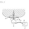
- the projecting portion 3 is designed so that the device mounting area Z is exposed to an outside of a body after the insertion portion 2 is inserted into a body organ ( FIG. 2 ).
- a length, a diameter, a shape, and other dimensions of the projecting portion 3 may be suitably designed. The above-mentioned dimensions and shape may be the same as or different from those of existing anal or vaginal probes.
- Sensing electrodes 6 are provided on an outer peripheral surface of the insertion portion 2.
- Two sensing electrodes 6 (6X and 6Y) are provided on an outer peripheral surface of the projecting portion 3 so as to be opposed to each other.
- the two sensing electrodes 6X and 6Y are each, for example, an electroconductive thin metal plate, metal film, or thin metal film.
- the sensing electrodes 6X and 6Y When the sensing electrodes 6X and 6Y are thin metal plates or metal films, the sensing electrodes 6X and 6Y can be fixed onto an outer peripheral surface of the base 4. A suitable method may be used as fixing means. When thin films are used as the sensing electrodes 6X and 6Y, the thin films may be formed on the outer peripheral surface of the base 4 by means such as adhesion, spraying, or coating. A length and a width of each of the two sensing electrodes 6X and 6Y are set to allow the insertion portion 2 to be brought into contact with a body-organ muscle when the insertion portion 2 is inserted into a body organ. In FIGS. 1 and FIG. 2 , the sensing electrodes 6X and 6Y extend from the insertion portion 2 to the device mounting area Z ( FIGS.
- the external-device coupler (hereinafter simply referred to as "coupler") 8 is electrically connected to a signal processing unit 10 of an external device 7 via a lead wire 9 ( FIG. 2 ).
- the external device 7 is an electromyograph.
- the electromyograph is merely an example.
- any other devices that are capable of generating perceivable information (perceivable signal) to be used for biofeedback based on the biosignal detected by the sensing electrodes may be used as the external device 7.
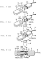
- the coupler 8 illustrated in FIG. 3(a) to FIG. 3(d) includes a male coupler member 11 and a female coupler member 12, which can removably mate to each other.
- the male coupler member 11 includes male electrodes 13 (13X and 13Y).
- the female coupler member 12 has two insertion holes 14 (14X and 14Y) into which the male electrodes 13X and 13Y are insertable.
- the two male electrodes 13X and 13Y are parallel in a longitudinal direction.
- the two insertion holes 14X and 14Y are formed so as to be parallel on an inlet side and become closer to each other in a depth direction.
- the male electrodes 13X and 13Y are brought closer to each other and brought into pressure-contact with the sensing electrodes 6Xb and 6Yb of the probe 1.
- the sensing electrodes 6X and 6Y become conductive with the male electrodes 13X and 13Y of the coupler 8 and the signal processing unit 10 via the lead wire 9, allowing the biosignal detected by the sensing electrodes 6X and 6Y to be transmitted to the signal processing unit 10.
- Protrusions 15 are formed on inner surfaces of the male coupler member 11 and the female coupler member 12 illustrated in FIGS. 3 , respectively.
- the signal processing unit 10 is configured to process the biosignal detected by the sensing electrodes 6X and 6Y on the insertion portion 2.
- FIG. 4 Another example of the coupler 8 is illustrated in FIG. 4 .
- the coupler 8 is a clip.
- the clip can be opened and closed like a general-purpose clothespin.
- the coupler 8 includes clamping electrodes 17 (17X and 17Y) provided on inner surfaces at distal ends of the coupler 8, and operating portions 18X and 18Y on a rear side.
- FIG. 4 illustration is given of a state in which the two clamping electrodes 17X and 17Y are closed to clamp and hold the sensing electrodes 6Xb and 6Yb of the probe 1.
- the two operating portions 18X and 18Y are moved closer to each other in directions indicated by arrows "a"
- the distal ends are opened in directions indicated by arrows "b” to release the clamping.
- the sensing electrodes 6X and 6Y become electrically conductive with the clamping electrodes 17X and 17Y and the signal processing unit 10 via the lead wire 9.
- the clamping is released, the conduction is interrupted.
- FIG. 5 Another example of the probe 1 according to the present invention, which is illustrated in FIG. 5 , is also an integrated probe including the insertion portion 2 and the projecting portion 3 that are continuous with each other.
- the probe 1 also includes the two sensing electrodes 6X and 6Y that are arranged on the projecting portion 3 so as to be opposed to each other.
- Two electrode protrusions 20 (20X and 20Y) are formed in a protruding manner on upper parts of the sensing electrodes 6X and 6Y, respectively.
- One electrode protrusion 20X is illustrated in FIG. 5 .
- another electrode protrusion 20Y is located on a back side of the electrode protrusion 20X, and thus is not illustrated in FIG. 5 .
- An end of the base 4 is divided into two parts by a division groove 21, and the two parts can be horizontally opened and closed.
- An upper groove 22 having a longitudinally elongated shape and a lower groove 23 having a horizontally elongated shape are formed below the division groove 21 to pass through the base 4 in a width direction.
- Rotation stopping protrusions 24 are formed in a protruding manner on the outer peripheral surface of the base 4 so as to be adjacent to the upper groove 22.
- the coupler 8 illustrated in FIG. 5 which is to be coupled to the probe 1, includes a coupler main body 25 and an extension arm member 26 as illustrated in FIG. 5 and FIG. 6 .
- the coupler main body 25 has an ellipsoidal plate-like shape with a large thickness, and has a fitting hole 27 and a fitting recessed portion 28.
- the fitting hole 27 is formed in a center of the coupler main body 25 in a horizontal direction to vertically pass through the coupler main body 25.
- the fitting recessed portion 28 having a horizontally elongated shape is formed on a distal end side of the coupler main body 25.
- the fitting recessed portion 28 has an inner side (left side) communicating with the fitting hole 27 and has an open distal end (right end) on an outer peripheral surface of a distal end of the coupler main body 25.
- the coupler main body 25 has a fitting plate 29 in a center in a thickness direction of the coupler main body 25.
- a retaining protrusion 30 is formed at a distal end of the fitting plate 29 so as to protrude upward.
- Two electrode protrusions 31 (31X and 31Y) are formed on an inner peripheral surface of the fitting hole 27 so as to be opposed to each other.
- the lead wire 9 of the external device is directly connected to the electrode protrusions 31X and 31Y.
- the lead wire 9 is led out from a rear end of the coupler main body 25.
- a rotation stopper portion 32 ( FIG. 5 and FIG. 6 ) having a recessed shape is also formed in the inner peripheral surface of the fitting hole 27.
- the rotation stopper portion 32 may have a protruding shape.
- a regulating protrusion 27a may be formed on the inner peripheral surface of the fitting hole 27 so as to be closer to one opening of the fitting hole 27 as illustrated in FIG. 7(a) .
- the probe 1 can be inserted from a front side or a back side (any one of the sides) of the fitting hole 27.
- the probe 1 cannot be inserted from another one of the sides. This structure prevents insertion of the probe 1 into the fitting hole 27 with an inappropriate orientation.
- a distal end of the probe 1 abuts against the regulating protrusion 27a to thereby position the upper groove 22 of the probe 1 at a predetermined position.
- the extension arm member 26 illustrated in FIG. 5 includes an upper plate 33, a lower plate 34, and a fitting groove 35 defined between the upper plate 33 and the lower plate 34.
- the fitting groove 35 has an open left end, and has a horizontally elongated U-like shape in side view.
- a push-in protrusion 36 protrudes forward from a distal end of the upper plate 33.
- a stopper 37 protrudes downward from the distal end of the upper plate 33.
- the extension arm member 26 can reciprocally slide in directions indicated by arrows "a" and "b” in FIG. 6 .
- the fitting groove 35 is fitted over the fitting plate 29 of the fitting recessed portion 28.
- the stopper 37 is caught by the retaining protrusion 30 to retain the extension arm member 26 in the fitting recessed portion 28.
- the extension arm member 26 illustrated in FIG. 5 and FIG. 6 is inserted and placed in the coupler main body 25 as illustrated in FIG. 7(a) and FIG. 7(b) , and can reciprocally slide in directions indicated by arrows X and Y.
- the extension arm member 26 is slid in the direction indicated by the arrow X and is pulled out from the coupler main body 25 to expose the fitting hole 27.
- FIG. 7(b) after a separation sheet 50 is placed and the probe 1 is inserted into the fitting hole 27, the extension arm member 26 is pushed into the direction indicated by the arrow Y to fix the probe 1 in the fitting hole 27. Under this fixed state, the sensing electrodes 6X and 6Y of the probe 1 are held in contact with the electrode protrusions 31X and 31Y of the coupler 8 to achieve a conductive state.
- the probe 1 is inserted into the fitting hole 27 of the coupler 8 as illustrated in FIG. 8(a) and FIG. 8(b) .
- the projecting portion 3 of the probe 1 is inserted vertically into the fitting hole 27 of the coupler main body 25.
- the rotation stopping protrusion 24 ( FIG. 6 ) formed on the outer peripheral surface of the base 4 of the probe 1 is fitted into the rotation stopper portion 32 ( FIG. 5 and FIG. 6 ) formed in the inner peripheral surface of the fitting hole 27 to thereby prevent spinning of the probe 1.
- the extension arm member 26 is pushed into the fitting recessed portion 28 of the coupler main body 25 to insert the push-in protrusion 36 of the extension arm member 26 into the upper groove 22 ( FIG.
- the lower plate 34 of the extension arm member 26 is inserted into the lower groove 23 of the base 4 to ensure the contact between the electrode protrusions 20X and 20Y formed on the sensing electrodes 6X and 6Y and the electrode protrusions (coupling electrodes) 31X and 31Y formed inside the fitting hole 27 of the coupler 8.
- This coupling enables the electrode protrusions 20X and 20Y formed on the sensing electrodes 6X and 6Y to become conductive with the coupling electrodes 31X and 31Y formed inside the fitting hole 27 and the signal processing unit 10 via the lead wire 9.
- the biosignal detected by the sensing electrodes 6X and 6Y is transmitted to the signal processing unit 10.
- the probe 1 is a disassemblable probe in which the insertion portion 2 and the projecting portion 3 can be separated from each other at a suitable position on the base 4 having a rod-like or cylindrical shape in a longitudinal direction of the probe 1.
- Basic shapes of the insertion portion 2 and the projecting portion 3 are the same as those illustrated in FIG. 1(a) . It is preferred that the insertion portion 2 and the projecting portion 3 have a coupling and decoupling structure (coupling and decoupling mechanism) that enables the projecting portion 3 to be separated from the insertion portion 2 by a single operation without the insertion portion 2 being touched by a hand.
- the probe 1 illustrated in FIG. 10(b) includes a small-diameter portion 40 at one longitudinal end of the projecting portion 3.
- the small-diameter portion 40 can be press-fitted into an internal hole 41 of the insertion portion 2 to achieve coupling.
- sensing electrodes 6Xa and 6Ya on the insertion portion 2 and the sensing electrodes 6Xb and 6Yb on the projecting portion 3 become conductive with each other.
- the coupler 8 can be fitted over and removed from an outer periphery of the projecting portion 3 of the probe 1 of FIG. 10(a) .
- the coupler 8 of FIG. 10(a) has a ring shape that enables fitting over the outer periphery of the projecting portion 3.
- the coupler 8 has an internal hole 42 that is tapered downward, and electrodes (coupler electrodes) 43X and 43Y that are formed on an inner surface of the internal hole 42 so as to be opposed to each other.
- the probe 1 is disposable regardless of whether the probe 1 is an integrated probe or a disassemblable probe.
- an inexpensive material suitable for single use for example, a resin, a rubber, or paper, is used as a material.
- the coupler 8 of FIG. 10(a) and FIG. 10(b) When the internal hole 42 of the coupler 8 of FIG. 10(a) and FIG. 10(b) is fitted over an outer periphery of the device mounting area Z of the probe 1, the coupler 8 is coupled to the projecting portion 3 to make the coupler electrodes 43X and 43Y conductive with the sensing electrodes 6X and 6Y of the probe 1.
- the sensing electrodes 6X and 6Y become conductive with the coupler electrodes 43X and 43Y and the signal processing unit 10 via the lead wire 9.
- the biosignal detected by the sensing electrodes 6X and 6Y is transmitted to the signal processing unit 10.
- the sensing electrodes 6X and 6Y of the probe 1 are electrically connected to the external device 7 by coupling the coupler 8 onto the device mounting area Z of the probe 1.
- the coupler 8 may be omitted in some cases.
- the lead wire 9 is directly connected to the sensing electrodes 6X and 6Y of the probe 1, and a distal end of the lead wire 9 is connected to the external device 7.
- the projecting portion 3 to which the lead wire 9 is connected may be repeatedly used, and only the insertion portion 2 may be discarded after single use.
- the integrated probe and the disassemblable probe can each be formed of a plurality of members as illustrated in FIG. 11(a) and FIG. 11(b) in terms of productivity.
- the probe 1 illustrated in FIG. 11(a) and FIG. 11(b) includes a main body portion 45 and two mounted members 46 (mounted members 46X and 46Y).
- the main body portion 45 includes the base 4 and the expanded portion 5.
- the mounted members 46 are mounted onto the main body portion 45.
- Two fitting grooves 45Xa and 45Ya are formed in an outer periphery of the base 4 of the main body portion 45 so as to be opposed to each other.
- Two coupling-portion fitting holes 45c are formed in an intermediate portion 45b between the fitting grooves 45Xa and 45Ya so as to be spaced apart from each other in a longitudinal direction of the base 4.
- the mounted members 46X and 46Y include head portions 46Xa and 46Ya and shaft-shaped portions 46Xb and 46Yb, respectively.
- the head portions 46Xa and 46Ya each have a semicylindrical shape.
- the shaft-shaped portions 46Xb and 46Yb are formed to protrude downward from the head portions 46Xa and 46Yz in FIG. 11(a) and FIG. 11(b) , respectively.
- Recessed portions 46Xc and 46Yc each having a horizontally elongated rectangular shape, are formed on surfaces of the head portions 46Xa and 46Ya, which are opposed to the counterparts of the mounted members 46X and 46Y, respectively.
- Electrode placement portions 46Xd and 46Yd are formed on arc-shaped surfaces of the head portions 46Xa and 46Ya, respectively.
- the shaft-shaped portions 46Xb and 46Yb are rod-shaped portions to be fitted into the fitting grooves 45Xa and 45Ya of the main body portion 45, respectively.
- the shaft-shaped portions 46Xb and 46Yb include coupling portions 46Xe and 46Ye to be coupled to counterparts of the mounted members 46X and 46Y.
- the coupling portions 46Xe and 46Ye are formed on surfaces of the shaft-shaped portions 46Xb and 46Yb, which are opposed to the counterparts thereof.
- Two coupling portions 46Xe and two coupling portions 46Ye are formed on the shaft-shaped portions 46Xb and 46Yb in a protruding manner so as to be spaced apart from each other in a longitudinal direction of the shaft-shaped portions 46Xb and 46Yb, respectively.
- Each of a distance between the two coupling portions 46Xe and a distance between two coupling portions 46Ye is set to be the same as a distance between coupling-portion fitting holes 45c of the main body portion 45.
- the two mounted members 46X and 46Y have the same shape.
- the same shape of the two mounted members 46X and 46Y allows manufacturing of the mounted members 46X and 46Y with use of a single molding die. Thus, manufacturing cost can be reduced.
- the coupling portions 46Xe and 46Ye are formed at positions on the right side with respect to a center of the shaft-shaped portions 46Xb and 46Yb in a width direction (lateral direction), respectively. These positions allow connection of opposed inner surfaces of the coupling portions 46Xe and 46Ye when the two mounted members 46X and 46Y are placed to be opposed to each other.
- the sensing electrodes 6X and 6Y are fitted over and held onto outer sides of the shaft-shaped portions 46Xb and 46Yb.
- the sensing electrodes 6X and 6Y are slid from lower ends (ends opposite to the head portions 46Xa and 46Ya) of the shaft-shaped portions 46Xb and 46Yb to cover the outer sides of the shaft-shaped portions 46Xb and 46Yb.
- the mounted members 46X and 46Y are mounted onto the main body portion 45, the sensing electrodes 6X and 6Y are exposed to an outside.
- the main body portion 45 and the two mounted members 46X and 46Y are integrated as illustrated in FIG. 12 in the following manner.
- the shaft-shaped portions 46Xb and 46Yb of the mounted members 46X and 46Y are fitted into the fitting grooves 45Xa and 45Ya of the main body portion 45 to couple the coupling portions 46Xe and 46Ye formed on the shaft-shaped portions 46Xb and 46Yb together in the coupling-portion fitting holes 45c.
- the upper groove 22 is defined at a position at which the recessed portions 46Xc and 46Yc of the mounted members 46X and 46Y that are coupled together are opposed to each other.
- An upper fitting groove 22a is defined at a position at which the upper recessed portions 46Xf and 46Yf are opposed to each other, and a lower fitting groove 22b is defined at a position at which the lower recessed portions 46Xg and 46Yg are opposed to each other.
- the push-in protrusion 36 of the extension arm member 26 is fitted into the upper groove 22.
- the rotation stopper portion 32 (see FIG. 5 ) is formed in a protruding shape, the rotation stopper portion 32 is fitted into the upper fitting groove 22a or the lower fitting groove 22b.
- the fitting of the rotation stopper portion 32 having a protruding portion into the upper fitting groove 22a or the lower fitting groove 22b prevents spinning of the probe 1.
- the sensing electrodes 6X and 6Y are illustrated as an example.
- the sensing electrodes 6X and 6Y may be formed by attaching electroconductive films, for example, metallic foils onto outer sides of the shaft-shaped portions 46Xb and 46Yb.
- the mounted members 46X and 46Y are coupled together to fix the mounted members 46X and 46Y onto the main body portion 45 as an example.
- the mounted members 46X and 46Y may be individually fixed onto the main body portion 45. Further, in the example illustrated in FIG. 11(a) and FIG.
- the main body portion 45 is formed of one member, and the mounted members 46X and 46Y are formed of two members as an example.
- the main body portion 45 may be formed of two or more members, and each of the mounted members 46 may be formed of one member or formed of three or more members.
- the separation sheet 50 can be mounted onto the base 4 of the probe 1 according to the present invention as illustrated in FIG. 7(a) and FIG. 7(b) .
- the separation sheet 50 illustrated as an example has a disc-like shape, and has a hole 51 formed in a center.
- the base 4 of the probe 1 can be inserted into the hole 51.
- the separation sheet 50 may have a shape other than the disc-like shape. It is preferred that the separation sheet 50 be made of an elastic material to allow close contact with the base 4 that has been inserted or be fixed to the base 4 by suitable means, for example, with an adhesive tape or an adhesive so as to prevent positional misalignment in an axial direction of the base 4 or unintended removal from the base 4.
- the separation sheet 50 is mounted on an outer side of a periphery of the base 4 of the probe 1 to separate a part of the probe 1, which is closer to the insertion portion 2, and a part of the probe 1, which is closer to the coupler 8, from each other.
- the separation sheet 50 can be placed so as to be in contact with buttocks.
- the separation sheet 50 receives a body fluid (leakage) that leaks from the body organ and flows down the insertion portion 2 to thereby prevent contact of the body fluid with the projecting portion 3 of the probe 1.
- the separation sheet 50 is formed separately from the probe 1, and is mountable to and removable from the base 4 of the probe 1.
- the separation sheet 5 may be mounted in advance onto the base 4, and may be integrated with the base 4 by another means in some cases. It is preferred that the separation sheet 50 be made of an inexpensive disposable material and have water proofness.
- the separation sheet 50 may also be made of a soft material that can easily be placed so as to be in contact with buttocks or an elastic material that enables easy mounting around the projecting portion 3.
- the separation sheet 50 which is made of an elastic material, allows easy insertion of the probe 1 into the hole 51 and prevents unintended removal of the probe 1 from the hole 51 after the insertion of the probe 1.
- the probe 1 and the separation sheet 50 described above can be stored in a package, for example, a packaging bag 52 as illustrated in FIG. 9(a) and FIG. 9(b) .
- the packaging bag 52 illustrated in FIG. 9(a) and FIG. 9(b) is made of a material that allows the packaging bag 52 to be opened with, for example, hands or scissors, and is made of, for example, a resin or paper.
- an upper part of the packaging bag 52 is cut away as illustrated in FIG. 9(b) to allow the separation sheet 50 to be taken out of the packaging bag 52.
- the projecting portion 3 of the probe 1 that is kept in the packaging bag 52 is directly pushed into the hole 51 of the separation sheet 50 to mount the separation sheet 50 around the probe 1.
- the coupler 8 ( FIG. 5 ) is mounted onto the device mounting area Z of the probe 1 that is kept (remains) in the packaging bag 52 as illustrated in FIG. 7(a) and FIG. 7(b) .
- the separation sheet 50 and the coupler 8 can be mounted without allowing the insertion portion 2 of the probe 1 to be touched by a hand.
- the coupler 8 is removed from the projecting portion 3 of the probe 1.
- the probe 1, which has been removed from the body organ is placed into the packaging bag 52 again with the insertion portion 2 side facing downward.
- the insertion portion 2 is discarded (after single use) together with the packaging bag 52.
- the package may be other than a packaging bag, and may be a container made of a thin flexible resin or paper. However, it is preferred that the package be made of a material suitable for single use, for example, paper or a resin film, and have a space-saving shape.
- the probe 1 alone may be packaged.
- the packaging bag 52 may be formed to allow the insertion portion 2 side of the probe 1 to be exposed to the outside.
- the projecting portion 3 may be held together with the packaging bag 52 with a hand to allow the insertion portion 2 to be inserted into a body organ.
- the insertion portion 2 can be inserted into a body organ without being touched by a hand, and thus is hygienic.
- the biosignal detected by the sensing electrodes 6X and 6Y is weak regardless of whether the probe 1 is an integrated probe or a disassemblable probe. Thus, it is difficult to directly process the biosignal with an electromyograph. After the biosignal is amplified and an unnecessary signal (mainly, noise) is removed therefrom in the signal processing unit 10, the biosignal is extracted.
- the signal processing unit 10 measures a potential difference between the thus extracted biosignal and reference electrodes O ( FIG. 13 ) attached onto a different portion of a body surface, for example, a surface of an abdomen.
- An example of the external device 7 to be connected to the probe 1 according to the present invention is an electromyograph.
- An example of the signal processing unit 10 of the electromyograph is illustrated in FIG. 13 .
- the signal processing unit 10 illustrated in FIG. 13 is the same as a signal processing unit of a general-purpose electromyograph.
- the signal processing unit includes high-pass filters F1 and F2, amplifiers AMP1 and AMP2, a differential amplifier AMP3, a notch filter F3, a low-pass filter F4, and an analog-digital converter ADC.
- the high-pass filters F1 and F2 are connected to the two sensing electrodes 6X and 6Y of the probe 1, respectively.
- the amplifiers AMP1 and AMP2 are configured to amplify signals from the high-pass filters F1 and F2, respectively.
- the notch filter F3 is configured to block passage of a signal at a specific frequency among signals from the differential amplifier and allow passage of a signal at other frequencies.
- the low-pass filter F4 is configured to allow passage of a low-frequency signal among signals from the notch filter F3.
- a biofeedback device includes a monitor 60. As illustrated in FIG. 14(a) , the sensing electrodes 6 of the probe 1 and the reference electrodes (electromyograph electrodes) O attached at suitable positions on a body surface are connected to the signal processing unit 10.
- the signal processing unit 10 is connected to the monitor 60. An image generated based on the biosignal that has been processed in the signal processing unit 10 is displayed on the monitor 60. The same image signal as the image signal is transmitted wirelessly or in a wired manner to a large auxiliary monitor 61 to display an image thereon. The image can be checked (viewed) by a doctor G and a patient H as illustrated in FIG. 14(b) to be used for biofeedback evaluations and treatments.
- the signal processing unit 10 can also generate perceivable information other than image information, for example, audio information based on the biosignal.
- the perceivable information described above can be stored in a storage device.
- a coupling structure for the projecting portion 3 and the coupler 8 may be other configurations (mechanisms) as long as the object of the present invention is achieved.
- the probe 1 illustrated in the drawings may also be inserted into measurement sites other than an anus or a vagina, for example, a urethra or other sites to which the probe 1 can be inserted, and can be used to detect a biosignal of a muscle other than pelvic floor muscles.
- the probe 1 is designed to have a shape, a size, and other dimensions that allow easy insertion into the measurement site and prevent unintended removal therefrom.
- the probe 1 may be used not only to detect the biosignal but also to electrically stimulate various kinds of muscles of body organs.
- a device capable of generating a stimulus signal is used as the external device.
Landscapes
- Life Sciences & Earth Sciences (AREA)
- Health & Medical Sciences (AREA)
- Surgery (AREA)
- Animal Behavior & Ethology (AREA)
- Pathology (AREA)
- Engineering & Computer Science (AREA)
- Biomedical Technology (AREA)
- Heart & Thoracic Surgery (AREA)
- Medical Informatics (AREA)
- Molecular Biology (AREA)
- Physics & Mathematics (AREA)
- Biophysics (AREA)
- General Health & Medical Sciences (AREA)
- Public Health (AREA)
- Veterinary Medicine (AREA)
- Gynecology & Obstetrics (AREA)
- Reproductive Health (AREA)
- Biodiversity & Conservation Biology (AREA)
- Measurement And Recording Of Electrical Phenomena And Electrical Characteristics Of The Living Body (AREA)
- Measuring And Recording Apparatus For Diagnosis (AREA)
- Orthopedics, Nursing, And Contraception (AREA)
Abstract
Description
- The present invention relates to a probe that is to be inserted into an anus, a woman's vagina, or other measurement site and used for measurement of an action potential (myopotential) of pelvic floor muscles (an external anal sphincter and an internal anal sphincter), a packaged probe including the probe contained in a package, an external-device coupler that enables coupling of an external device (for example, an electromyograph) to the probe, and a biofeedback device that generates perceivable information based on a biosignal detected by the probe.
- An electromyograph is a device (measurement device) that detects a biosignal (body signal) resulting from a muscle activity of, for example, an external anal sphincter or pelvic floor muscles to measure a muscle strength, a change in muscle strength, or the like (perform muscle strength measurement) of the external anal sphincter or the pelvic floor muscles so as to strengthen the muscle or treat and prevent urine leakage or incontinence while checking the measured biosignal. An electromyograph probe, which is inserted into a measurement site (hereinafter referred to as "body organ") such as an anus or a vagina, is used to detect a biosignal. Electromyograph probes (hereinafter referred to as "probes") are commercially available, and have various shapes (
Non Patent Literatures 1 to 7). - A representative one of probes described in
Non Patent Literatures 1 to 7 mainly includes, as illustrated inFIG. 15 , an insertion portion A to be inserted into a body organ, and two electrodes C. The electrodes C are provided on an outer peripheral surface of a shaft B of the insertion portion A so as to be opposed to each other. When the insertion portion A is inserted into a body organ in such a manner that the entire shaft B is fully placed inside the body organ, both the electrodes C are brought into contact with, for example, the external anal sphincter or the pelvic floor muscles to detect a biosignal from the muscles described above. The biosignal detected by the two electrodes C is transmitted to a signal processing unit D of an electromyograph, and a potential difference from reference electrodes attached at suitable positions on a surface of the body is measured. - The probe is inserted into a body organ. Thus, from a hygienic viewpoint, the probe is generally discarded after each use. However, when each probe is discarded after single use, cost increases for the following reasons. Each probe is as expensive as several thousand Japanese yen. In addition, as illustrated in
FIG. 15 , a lead wire (cable) E led out from the signal processing unit D of the electromyograph is directly attached (fixed) inside a handle F of the probe. Further, each of the insertion portion A, the electrodes C, and the lead wire E has a mechanical strength that allows repeated use. Thus, it is regrettable to discard the above-mentioned components after single use. Under current conditions, the probe is disinfected or sterilized after each use for subsequent use. However, such use of the probe may lead to hygienic problems, and users may be reluctant to use the probe in the above-mentioned manner. -
- [NPL 1] http://www.medicalexpo.com/ja/prod/thought-technology/product-70321-739531.html
- [NPL 2] https://www.biostim.no/produkt/rektal-sensor-u-control-bekkenbunnopptrener/
- [NPL 3] http://www.medicalexpo.it/prod/beacmed/product-67740-600829.html
- [NPL 4] https://beckenboden-trainer.de/sonden/vaginalsonden/32/vaginalsonde-bei-inkontinenz.-beckenbodenmuskulatur
- [NPL 5] https://ja.aliexpress.com/store/product/Super-Slim-Vaginal-or-Anal-Probe-for-EMG-STIM-EMS-Biofeedback-EMG-TENS-PELVIC-FLOOR-EXERCISERS/234181_32414048195.html
- [NPL 6] https://www.advantagemedical.com/products/pathway-rectal-sensor-for-emg-and-e-stim/
- [NPL 7] https://medicalquip.com/product/rectal-sensor-with-stim/
- An object of the present invention is to provide a probe that is easy to use and hygienic, a packaged probe that is usable hygienically, an external-device coupler that enables easy coupling of an external device to the probe, and a biofeedback device that perceptualizes a biosignal detected by the probe.
- According to the present invention, there is provided a probe including an insertion portion insertable into a body organ and a projecting portion that is exposed to an outside of a body after the insertion portion is inserted into the body organ. The projecting portion has a device mounting area. Electrodes (hereinafter referred to as "sensing electrodes") that detect a biosignal when the insertion portion is inserted into the body organ are provided on the insertion portion and the device mounting area. When an external-device coupler is mounted onto the device mounting area, the biosignal detected by the sensing electrodes is transmitted to an external device.
- According to the present invention, there is provided a packaged probe including a package that contains the probe. A part of the package can be cut away to open the package. When the package is opened, the insertion portion or the projecting portion of the probe is exposed from an opening and another one of the insertion portion and the projecting portion remains in the package. A separation sheet may be packaged together with the probe. When the separation sheet is placed on an outer periphery of the projecting portion, the separation sheet can prevent contact of a leakage flowing out from the body organ with the projecting portion.
- According to the present invention, there is provided an external-device coupler including a mounting portion removably mountable to the device mounting area of the probe and electrodes (hereinafter referred to as "coupling electrodes") to be brought into contact with the sensing electrodes of the probe to become conductive with the sensing electrodes when the mounting portion is mounted to the device mounting area.
- According to the present invention, there is provided a biofeedback device that enables use of perceivable information for biofeedback evaluations and treatments. The perceivable information is generated in the external device after the biosignal detected by the sensing electrodes of the probe is transmitted to the external device via the external-device coupler. The perceivable information includes, for example, image information and audio information. When the perceivable information is the image information, an image is displayed on a monitor screen. The image can be viewed and used for biofeedback evaluations and treatments. The perceivable information may be stored in a storage device.
- The probe according to the present invention has the following effects.
- 1. When the insertion portion is inserted into a body organ, the sensing electrodes detect the biosignal.
- 2. When the external-device coupler is mounted onto the device mounting area, the biosignal detected by the sensing electrodes can be transmitted to the external device.
- 3. When a separation sheet is mounted around the projecting portion, the separation sheet stops flow of a leakage from a body organ and prevents the leakage from coming into contact with the projecting portion. Thus, contact of a hand with the leakage is prevented, and thus the probe is hygienic.
- When a part of the package of the packaged probe according to the present invention is cut away to open the package, the insertion portion or the projecting portion is exposed to an outside of the package. The insertion portion or the projecting portion, which remains in the package, is held with a hand together with the package, and thus can be inserted into and removed from a body organ without being directly touched by a hand. Thus, the packaged probe is hygienic.
- The external-device coupler according to the present invention enables easy mounting of the external device to the device mounting area of the probe. Thus, the biosignal detected by the probe can be reliably transmitted to the external device.
- The biofeedback device according to the present invention enables the biosignal detected by the sensing electrodes of the probe to be checked in the form of the perceivable information. Thus, the biofeedback device can be effectively used for biofeedback evaluations and treatments.
-
-
FIG. 1(a) is a perspective view of an example of a probe according to the present invention, andFIG. 1(b) is a perspective view for illustrating a state in which a separation sheet is mounted around an insertion portion of the probe. -
FIG. 2 is an explanatory view for illustrating a state in which the probe according to the present invention is inserted into a body organ and the separation sheet is placed so as to be in contact with buttocks. -
FIG. 3(a), FIG. 3(b), FIG. 3(c), and FIG. 3(d) are explanatory views for illustrating a case in which an electromyograph is coupled to a projecting portion of the probe according to the present invention with an external-device coupler. -
FIG. 4 is an explanatory view for illustrating a case in which the external-device coupler to be coupled to the probe according to the present invention is a clip. -
FIG. 5 is an explanatory view of another example of the probe and the external-device coupler according to the present invention. -
FIG. 6 is an explanatory view for illustrating mounting of the probe and the external-device coupler illustrated inFIG. 5 . -
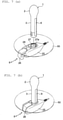
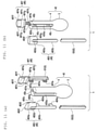
FIG. 7(a) is an explanatory view of the external-device coupler before insertion of an extension arm member, andFIG. 7(b) is an explanatory view of the external-device coupler after the insertion of the extension arm member. -
FIG. 8(a) is a plan view of the external-device coupler ofFIG. 5 ,FIG. 8(b) is an explanatory side view for illustrating a case in which the external-device coupler ofFIG. 5 is mounted to the probe,FIG. 8(c) is a front view of the extension arm member ofFIG. 5 , andFIG. 8(d) is a plan view of the separation sheet. -
FIG. 9(a) is an explanatory view of a packaged probe according to the present invention, andFIG. 9(b) is an explanatory view for illustrating a state in which an upper half of a package illustrated inFIG. 9(a) is cut away. -
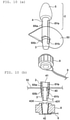
FIG. 10(a) is a perspective view of another example of the probe according to the present invention, andFIG. 10(b) is an explanatory view for illustrating coupling between the insertion portion and the external-device coupler illustrated inFIG. 10(a) . -
FIG. 11(a) is a perspective view for illustrating an example in which a probe is formed of a plurality of members, andFIG. 11(b) is a perspective view of the probe ofFIG. 11(a) when viewed from a different angle. -
FIG. 12 is a perspective view for illustrating a state in which the probe illustrated inFIG. 11(a) and FIG. 11(b) is assembled. -
FIG. 13 is an explanatory block diagram of a signal processing unit of an electromyograph. -
FIG. 14(a) is a schematic view of a biofeedback device according to the present invention, andFIG. 14(b) is an explanatory view for illustrating an evaluation and a treatment using the biofeedback device. -
FIG. 15 is an explanatory view of a related-art probe. - As an example of the present invention, a
probe 1 is illustrated inFIG. 1(a) . Theprobe 1 is an integrated probe including aninsertion portion 2 and a projectingportion 3 that are continuous with each other. Theinsertion portion 2 is located on a front end side of onebase 4 having a rod-like or cylindrical shape, and the projectingportion 3 is located on a rear end side thereof. A device mounting area Z (FIGS. 1 andFIG. 2 ) is defined on a rear end side of the projectingportion 3. - The
insertion portion 2 includes an expandedportion 5 provided on the front end side of thebase 4 and part of thebase 4, which is located on a side closer to a root of the expandedportion 5. Theinsertion portion 2 is to be inserted into a body organ. The expandedportion 5 is tapered for easy insertion into a body organ, and is also formed thicker than the projectingportion 3 for prevention of unintended removal from the body organ. A length, a diameter, a shape, and other dimensions of theinsertion portion 2 may be suitably designed. The above-mentioned dimensions and shape may be the same as or different from those of existing anal or vaginal probes. - The
insertion portion 2 can be inserted into a body organ. The projectingportion 3 is designed so that the device mounting area Z is exposed to an outside of a body after theinsertion portion 2 is inserted into a body organ (FIG. 2 ). A length, a diameter, a shape, and other dimensions of the projectingportion 3 may be suitably designed. The above-mentioned dimensions and shape may be the same as or different from those of existing anal or vaginal probes. - Sensing electrodes 6 (
FIG. 1(a) ) are provided on an outer peripheral surface of theinsertion portion 2. Two sensing electrodes 6 (6X and 6Y) are provided on an outer peripheral surface of the projectingportion 3 so as to be opposed to each other. The twosensing electrodes insertion portion 2 is inserted into a body organ, thesensing electrodes sensing electrodes sensing electrodes base 4. A suitable method may be used as fixing means. When thin films are used as thesensing electrodes base 4 by means such as adhesion, spraying, or coating. A length and a width of each of the twosensing electrodes insertion portion 2 to be brought into contact with a body-organ muscle when theinsertion portion 2 is inserted into a body organ. InFIGS. 1 andFIG. 2 , thesensing electrodes insertion portion 2 to the device mounting area Z (FIGS. 1 andFIG. 2 ) of the projectingportion 3. When an external-device coupler 8 (FIG. 2 ) is mounted onto the device mounting area Z (FIGS. 1 andFIG. 2 ), electrodes (coupling electrodes; not shown) of the external-device coupler 8 are brought into contact with sensing electrodes 6Xb and 6Yb so as to be electrically conductive therewith. - The external-device coupler (hereinafter simply referred to as "coupler") 8 is electrically connected to a
signal processing unit 10 of anexternal device 7 via a lead wire 9 (FIG. 2 ). In this embodiment, theexternal device 7 is an electromyograph. However, the electromyograph is merely an example. In the present invention, any other devices that are capable of generating perceivable information (perceivable signal) to be used for biofeedback based on the biosignal detected by the sensing electrodes may be used as theexternal device 7. - Various structures and mechanisms are conceivable for the
coupler 8. As an example, thecoupler 8 illustrated inFIG. 3(a) to FIG. 3(d) includes amale coupler member 11 and afemale coupler member 12, which can removably mate to each other. Themale coupler member 11 includes male electrodes 13 (13X and 13Y). Thefemale coupler member 12 has two insertion holes 14 (14X and 14Y) into which themale electrodes male electrodes insertion holes male electrodes insertion holes male electrodes probe 1. As a result, thesensing electrodes male electrodes coupler 8 and thesignal processing unit 10 via thelead wire 9, allowing the biosignal detected by thesensing electrodes signal processing unit 10.Protrusions 15 are formed on inner surfaces of themale coupler member 11 and thefemale coupler member 12 illustrated inFIGS. 3 , respectively. When themale coupler member 11 and thefemale coupler member 12 are brought into abutment against the outer peripheral surface of the projectingportion 3 as illustrated inFIG. 3(c) , theprotrusions 15 are inserted into recessed portions 16 (FIG. 3(b) and FIG. 3(d) ) formed on the outer peripheral surface of the projectingportion 3 to thereby prevent rotation of themale coupler member 11 and thefemale coupler member 12 about an axis of the projectingportion 3. Thesignal processing unit 10 is configured to process the biosignal detected by thesensing electrodes insertion portion 2. - Another example of the
coupler 8 is illustrated inFIG. 4 . Thecoupler 8 is a clip. The clip can be opened and closed like a general-purpose clothespin. Thecoupler 8 includes clamping electrodes 17 (17X and 17Y) provided on inner surfaces at distal ends of thecoupler 8, andoperating portions FIG. 4 , illustration is given of a state in which the twoclamping electrodes probe 1. When the two operatingportions probe 1 is clamped and held, thesensing electrodes electrodes signal processing unit 10 via thelead wire 9. When the clamping is released, the conduction is interrupted. - Another example of the
probe 1 according to the present invention, which is illustrated inFIG. 5 , is also an integrated probe including theinsertion portion 2 and the projectingportion 3 that are continuous with each other. Theprobe 1 also includes the twosensing electrodes portion 3 so as to be opposed to each other. Two electrode protrusions 20 (20X and 20Y) are formed in a protruding manner on upper parts of thesensing electrodes electrode protrusion 20X is illustrated inFIG. 5 . However, another electrode protrusion 20Y is located on a back side of theelectrode protrusion 20X, and thus is not illustrated inFIG. 5 . An end of thebase 4 is divided into two parts by adivision groove 21, and the two parts can be horizontally opened and closed. Anupper groove 22 having a longitudinally elongated shape and alower groove 23 having a horizontally elongated shape are formed below thedivision groove 21 to pass through thebase 4 in a width direction.Rotation stopping protrusions 24 are formed in a protruding manner on the outer peripheral surface of thebase 4 so as to be adjacent to theupper groove 22. - The
coupler 8 illustrated inFIG. 5 , which is to be coupled to theprobe 1, includes a couplermain body 25 and anextension arm member 26 as illustrated inFIG. 5 andFIG. 6 . The couplermain body 25 has an ellipsoidal plate-like shape with a large thickness, and has afitting hole 27 and a fitting recessedportion 28. Thefitting hole 27 is formed in a center of the couplermain body 25 in a horizontal direction to vertically pass through the couplermain body 25. The fitting recessedportion 28 having a horizontally elongated shape is formed on a distal end side of the couplermain body 25. The fitting recessedportion 28 has an inner side (left side) communicating with thefitting hole 27 and has an open distal end (right end) on an outer peripheral surface of a distal end of the couplermain body 25. The couplermain body 25 has afitting plate 29 in a center in a thickness direction of the couplermain body 25. A retainingprotrusion 30 is formed at a distal end of thefitting plate 29 so as to protrude upward. Two electrode protrusions 31 (31X and 31Y) are formed on an inner peripheral surface of thefitting hole 27 so as to be opposed to each other. Thelead wire 9 of the external device is directly connected to theelectrode protrusions 31X and 31Y. Thelead wire 9 is led out from a rear end of the couplermain body 25. A rotation stopper portion 32 (FIG. 5 andFIG. 6 ) having a recessed shape is also formed in the inner peripheral surface of thefitting hole 27. Therotation stopper portion 32 may have a protruding shape. - In order to prevent upside-down insertion of the
probe 1 into thefitting hole 27, a regulatingprotrusion 27a may be formed on the inner peripheral surface of thefitting hole 27 so as to be closer to one opening of thefitting hole 27 as illustrated inFIG. 7(a) . When the regulatingprotrusion 27a is formed, theprobe 1 can be inserted from a front side or a back side (any one of the sides) of thefitting hole 27. However, theprobe 1 cannot be inserted from another one of the sides. This structure prevents insertion of theprobe 1 into thefitting hole 27 with an inappropriate orientation. When theprobe 1 is inserted with a correct orientation, a distal end of theprobe 1 abuts against the regulatingprotrusion 27a to thereby position theupper groove 22 of theprobe 1 at a predetermined position. - The
extension arm member 26 illustrated inFIG. 5 includes anupper plate 33, alower plate 34, and afitting groove 35 defined between theupper plate 33 and thelower plate 34. Thefitting groove 35 has an open left end, and has a horizontally elongated U-like shape in side view. A push-inprotrusion 36 protrudes forward from a distal end of theupper plate 33. Astopper 37 protrudes downward from the distal end of theupper plate 33. Theextension arm member 26 can reciprocally slide in directions indicated by arrows "a" and "b" inFIG. 6 . When theextension arm member 26 is pushed in the direction indicated by the arrow "a", thefitting groove 35 is fitted over thefitting plate 29 of the fitting recessedportion 28. When theextension arm member 26 is pulled in the direction indicated by the arrow "b" as illustrated inFIG. 6 , thestopper 37 is caught by the retainingprotrusion 30 to retain theextension arm member 26 in the fitting recessedportion 28. - The
extension arm member 26 illustrated inFIG. 5 andFIG. 6 is inserted and placed in the couplermain body 25 as illustrated inFIG. 7(a) and FIG. 7(b) , and can reciprocally slide in directions indicated by arrows X and Y. InFIG. 7(a) , theextension arm member 26 is slid in the direction indicated by the arrow X and is pulled out from the couplermain body 25 to expose thefitting hole 27. InFIG. 7(b) , after aseparation sheet 50 is placed and theprobe 1 is inserted into thefitting hole 27, theextension arm member 26 is pushed into the direction indicated by the arrow Y to fix theprobe 1 in thefitting hole 27. Under this fixed state, thesensing electrodes probe 1 are held in contact with theelectrode protrusions 31X and 31Y of thecoupler 8 to achieve a conductive state. - The
probe 1 is inserted into thefitting hole 27 of thecoupler 8 as illustrated inFIG. 8(a) and FIG. 8(b) . The projectingportion 3 of theprobe 1 is inserted vertically into thefitting hole 27 of the couplermain body 25. At this time, the rotation stopping protrusion 24 (FIG. 6 ) formed on the outer peripheral surface of thebase 4 of theprobe 1 is fitted into the rotation stopper portion 32 (FIG. 5 andFIG. 6 ) formed in the inner peripheral surface of thefitting hole 27 to thereby prevent spinning of theprobe 1. Under this state, theextension arm member 26 is pushed into the fitting recessedportion 28 of the couplermain body 25 to insert the push-inprotrusion 36 of theextension arm member 26 into the upper groove 22 (FIG. 6 ) formed in a peripheral surface of thebase 4 of theprobe 1 as illustrated inFIG. 8(a) . As a result, two separate upper ends of thebase 4 are forced apart from each other in the horizontal direction to push theelectrode protrusions 20X and 20Y formed on thesensing electrodes probe 1 against theelectrode protrusions 31X and 31Y formed inside thefitting hole 27 to achieve contact therebetween. At this time, as illustrated inFIG. 8(b) , thelower plate 34 of theextension arm member 26 is inserted into thelower groove 23 of thebase 4 to ensure the contact between theelectrode protrusions 20X and 20Y formed on thesensing electrodes fitting hole 27 of thecoupler 8. This coupling enables theelectrode protrusions 20X and 20Y formed on thesensing electrodes coupling electrodes 31X and 31Y formed inside thefitting hole 27 and thesignal processing unit 10 via thelead wire 9. As a result, the biosignal detected by thesensing electrodes signal processing unit 10. - Another example of the
probe 1 according to the present invention is illustrated inFIG. 10(a) and FIG. 10(b) . Theprobe 1 is a disassemblable probe in which theinsertion portion 2 and the projectingportion 3 can be separated from each other at a suitable position on thebase 4 having a rod-like or cylindrical shape in a longitudinal direction of theprobe 1. Basic shapes of theinsertion portion 2 and the projectingportion 3 are the same as those illustrated inFIG. 1(a) . It is preferred that theinsertion portion 2 and the projectingportion 3 have a coupling and decoupling structure (coupling and decoupling mechanism) that enables the projectingportion 3 to be separated from theinsertion portion 2 by a single operation without theinsertion portion 2 being touched by a hand. As an example, theprobe 1 illustrated inFIG. 10(b) includes a small-diameter portion 40 at one longitudinal end of the projectingportion 3. The small-diameter portion 40 can be press-fitted into aninternal hole 41 of theinsertion portion 2 to achieve coupling. When theinsertion portion 2 and the projectingportion 3 are coupled to each other, sensing electrodes 6Xa and 6Ya on theinsertion portion 2 and the sensing electrodes 6Xb and 6Yb on the projectingportion 3 become conductive with each other. - The
coupler 8 can be fitted over and removed from an outer periphery of the projectingportion 3 of theprobe 1 ofFIG. 10(a) . Thecoupler 8 ofFIG. 10(a) has a ring shape that enables fitting over the outer periphery of the projectingportion 3. As illustrated inFIG. 10(b) , thecoupler 8 has aninternal hole 42 that is tapered downward, and electrodes (coupler electrodes) 43X and 43Y that are formed on an inner surface of theinternal hole 42 so as to be opposed to each other. - The
probe 1 is disposable regardless of whether theprobe 1 is an integrated probe or a disassemblable probe. In this case, an inexpensive material suitable for single use, for example, a resin, a rubber, or paper, is used as a material. - When the
internal hole 42 of thecoupler 8 ofFIG. 10(a) and FIG. 10(b) is fitted over an outer periphery of the device mounting area Z of theprobe 1, thecoupler 8 is coupled to the projectingportion 3 to make thecoupler electrodes sensing electrodes probe 1. Thus, thesensing electrodes coupler electrodes signal processing unit 10 via thelead wire 9. As a result, the biosignal detected by thesensing electrodes signal processing unit 10. - In
FIG. 10(a) and FIG. 10(b) , thesensing electrodes probe 1 are electrically connected to theexternal device 7 by coupling thecoupler 8 onto the device mounting area Z of theprobe 1. However, thecoupler 8 may be omitted in some cases. In such a case, thelead wire 9 is directly connected to thesensing electrodes probe 1, and a distal end of thelead wire 9 is connected to theexternal device 7. In this case, the projectingportion 3 to which thelead wire 9 is connected may be repeatedly used, and only theinsertion portion 2 may be discarded after single use. - The integrated probe and the disassemblable probe can each be formed of a plurality of members as illustrated in
FIG. 11(a) and FIG. 11(b) in terms of productivity. Theprobe 1 illustrated inFIG. 11(a) and FIG. 11(b) includes amain body portion 45 and two mounted members 46 (mountedmembers main body portion 45 includes thebase 4 and the expandedportion 5. The mountedmembers 46 are mounted onto themain body portion 45. - Two fitting grooves 45Xa and 45Ya, each being longitudinally elongated, are formed in an outer periphery of the
base 4 of themain body portion 45 so as to be opposed to each other. Two coupling-portionfitting holes 45c (FIG. 11(b) ) are formed in anintermediate portion 45b between the fitting grooves 45Xa and 45Ya so as to be spaced apart from each other in a longitudinal direction of thebase 4. - The mounted
members FIG. 11(a) and FIG. 11(b) , respectively. Recessed portions 46Xc and 46Yc, each having a horizontally elongated rectangular shape, are formed on surfaces of the head portions 46Xa and 46Ya, which are opposed to the counterparts of the mountedmembers - The shaft-shaped portions 46Xb and 46Yb are rod-shaped portions to be fitted into the fitting grooves 45Xa and 45Ya of the
main body portion 45, respectively. The shaft-shaped portions 46Xb and 46Yb include coupling portions 46Xe and 46Ye to be coupled to counterparts of the mountedmembers fitting holes 45c of themain body portion 45. - In the example illustrated in
FIG. 11(a) and FIG. 11(b) , the twomounted members mounted members members FIG. 11(a) and FIG. 11(b) , the coupling portions 46Xe and 46Ye are formed at positions on the right side with respect to a center of the shaft-shaped portions 46Xb and 46Yb in a width direction (lateral direction), respectively. These positions allow connection of opposed inner surfaces of the coupling portions 46Xe and 46Ye when the twomounted members - The
sensing electrodes sensing electrodes members main body portion 45, thesensing electrodes - The
main body portion 45 and the twomounted members FIG. 12 in the following manner. The shaft-shaped portions 46Xb and 46Yb of the mountedmembers main body portion 45 to couple the coupling portions 46Xe and 46Ye formed on the shaft-shaped portions 46Xb and 46Yb together in the coupling-portionfitting holes 45c. Theupper groove 22 is defined at a position at which the recessed portions 46Xc and 46Yc of the mountedmembers fitting groove 22a is defined at a position at which the upper recessed portions 46Xf and 46Yf are opposed to each other, and a lowerfitting groove 22b is defined at a position at which the lower recessed portions 46Xg and 46Yg are opposed to each other. The push-inprotrusion 36 of theextension arm member 26 is fitted into theupper groove 22. When the rotation stopper portion 32 (seeFIG. 5 ) is formed in a protruding shape, therotation stopper portion 32 is fitted into the upperfitting groove 22a or the lowerfitting groove 22b. The fitting of therotation stopper portion 32 having a protruding portion into the upperfitting groove 22a or the lowerfitting groove 22b prevents spinning of theprobe 1. - In the example illustrated in
FIG. 11(a) and FIG. 11(b) , thesensing electrodes sensing electrodes FIG. 11(a) and FIG. 11(b) , the mountedmembers members main body portion 45 as an example. However, the mountedmembers main body portion 45. Further, in the example illustrated inFIG. 11(a) and FIG. 11(b) , themain body portion 45 is formed of one member, and the mountedmembers main body portion 45 may be formed of two or more members, and each of the mountedmembers 46 may be formed of one member or formed of three or more members. - The
separation sheet 50 can be mounted onto thebase 4 of theprobe 1 according to the present invention as illustrated inFIG. 7(a) and FIG. 7(b) . Theseparation sheet 50 illustrated as an example has a disc-like shape, and has ahole 51 formed in a center. Thebase 4 of theprobe 1 can be inserted into thehole 51. Theseparation sheet 50 may have a shape other than the disc-like shape. It is preferred that theseparation sheet 50 be made of an elastic material to allow close contact with thebase 4 that has been inserted or be fixed to thebase 4 by suitable means, for example, with an adhesive tape or an adhesive so as to prevent positional misalignment in an axial direction of thebase 4 or unintended removal from thebase 4. Theseparation sheet 50 is mounted on an outer side of a periphery of thebase 4 of theprobe 1 to separate a part of theprobe 1, which is closer to theinsertion portion 2, and a part of theprobe 1, which is closer to thecoupler 8, from each other. When theinsertion portion 2 is inserted into a body organ as illustrated inFIG. 2 , theseparation sheet 50 can be placed so as to be in contact with buttocks. Theseparation sheet 50 receives a body fluid (leakage) that leaks from the body organ and flows down theinsertion portion 2 to thereby prevent contact of the body fluid with the projectingportion 3 of theprobe 1. - The
separation sheet 50 is formed separately from theprobe 1, and is mountable to and removable from thebase 4 of theprobe 1. Theseparation sheet 5 may be mounted in advance onto thebase 4, and may be integrated with thebase 4 by another means in some cases. It is preferred that theseparation sheet 50 be made of an inexpensive disposable material and have water proofness. Theseparation sheet 50 may also be made of a soft material that can easily be placed so as to be in contact with buttocks or an elastic material that enables easy mounting around the projectingportion 3. Theseparation sheet 50, which is made of an elastic material, allows easy insertion of theprobe 1 into thehole 51 and prevents unintended removal of theprobe 1 from thehole 51 after the insertion of theprobe 1. - The
probe 1 and theseparation sheet 50 described above can be stored in a package, for example, apackaging bag 52 as illustrated inFIG. 9(a) and FIG. 9(b) . Thepackaging bag 52 illustrated inFIG. 9(a) and FIG. 9(b) is made of a material that allows thepackaging bag 52 to be opened with, for example, hands or scissors, and is made of, for example, a resin or paper. When theprobe 1 and theseparation sheet 50, which are packaged, are used, an upper part of thepackaging bag 52 is cut away as illustrated inFIG. 9(b) to allow theseparation sheet 50 to be taken out of thepackaging bag 52. Then, the projectingportion 3 of theprobe 1 that is kept in thepackaging bag 52 is directly pushed into thehole 51 of theseparation sheet 50 to mount theseparation sheet 50 around theprobe 1. Next, the coupler 8 (FIG. 5 ) is mounted onto the device mounting area Z of theprobe 1 that is kept (remains) in thepackaging bag 52 as illustrated inFIG. 7(a) and FIG. 7(b) . In this case, theseparation sheet 50 and thecoupler 8 can be mounted without allowing theinsertion portion 2 of theprobe 1 to be touched by a hand. After use, thecoupler 8 is removed from the projectingportion 3 of theprobe 1. Theprobe 1, which has been removed from the body organ, is placed into thepackaging bag 52 again with theinsertion portion 2 side facing downward. Theinsertion portion 2 is discarded (after single use) together with thepackaging bag 52. The package may be other than a packaging bag, and may be a container made of a thin flexible resin or paper. However, it is preferred that the package be made of a material suitable for single use, for example, paper or a resin film, and have a space-saving shape. Theprobe 1 alone may be packaged. - The
packaging bag 52 may be formed to allow theinsertion portion 2 side of theprobe 1 to be exposed to the outside. In this case, the projectingportion 3 may be held together with thepackaging bag 52 with a hand to allow theinsertion portion 2 to be inserted into a body organ. In this case, theinsertion portion 2 can be inserted into a body organ without being touched by a hand, and thus is hygienic. - The biosignal detected by the
sensing electrodes probe 1 is an integrated probe or a disassemblable probe. Thus, it is difficult to directly process the biosignal with an electromyograph. After the biosignal is amplified and an unnecessary signal (mainly, noise) is removed therefrom in thesignal processing unit 10, the biosignal is extracted. Thesignal processing unit 10 measures a potential difference between the thus extracted biosignal and reference electrodes O (FIG. 13 ) attached onto a different portion of a body surface, for example, a surface of an abdomen. - An example of the
external device 7 to be connected to theprobe 1 according to the present invention is an electromyograph. An example of thesignal processing unit 10 of the electromyograph is illustrated inFIG. 13 . Thesignal processing unit 10 illustrated inFIG. 13 is the same as a signal processing unit of a general-purpose electromyograph. The signal processing unit includes high-pass filters F1 and F2, amplifiers AMP1 and AMP2, a differential amplifier AMP3, a notch filter F3, a low-pass filter F4, and an analog-digital converter ADC. The high-pass filters F1 and F2 are connected to the twosensing electrodes probe 1, respectively. The amplifiers AMP1 and AMP2 are configured to amplify signals from the high-pass filters F1 and F2, respectively. The notch filter F3 is configured to block passage of a signal at a specific frequency among signals from the differential amplifier and allow passage of a signal at other frequencies. The low-pass filter F4 is configured to allow passage of a low-frequency signal among signals from the notch filter F3. - A biofeedback device according to the present invention includes a
monitor 60. As illustrated inFIG. 14(a) , thesensing electrodes 6 of theprobe 1 and the reference electrodes (electromyograph electrodes) O attached at suitable positions on a body surface are connected to thesignal processing unit 10. Thesignal processing unit 10 is connected to themonitor 60. An image generated based on the biosignal that has been processed in thesignal processing unit 10 is displayed on themonitor 60. The same image signal as the image signal is transmitted wirelessly or in a wired manner to a largeauxiliary monitor 61 to display an image thereon. The image can be checked (viewed) by a doctor G and a patient H as illustrated inFIG. 14(b) to be used for biofeedback evaluations and treatments. Thesignal processing unit 10 can also generate perceivable information other than image information, for example, audio information based on the biosignal. The perceivable information described above can be stored in a storage device. - The embodiments described above are each an example of the present invention, and the present invention is not limited to the embodiments described above. In the case of the disassemblable probe, in particular, for example, the coupling and decoupling structure for the
insertion portion 2 and the projectingportion 3, the structure (mechanism) and the shape of thecoupler 8 configured to allow connection between the projectingportion 3 of theprobe 1 and thesignal processing unit 10, a coupling structure for the projectingportion 3 and thecoupler 8 may be other configurations (mechanisms) as long as the object of the present invention is achieved. Further, theprobe 1 illustrated in the drawings may also be inserted into measurement sites other than an anus or a vagina, for example, a urethra or other sites to which theprobe 1 can be inserted, and can be used to detect a biosignal of a muscle other than pelvic floor muscles. In this case, theprobe 1 is designed to have a shape, a size, and other dimensions that allow easy insertion into the measurement site and prevent unintended removal therefrom. Theprobe 1 may be used not only to detect the biosignal but also to electrically stimulate various kinds of muscles of body organs. In this case, a device capable of generating a stimulus signal is used as the external device. -
- 1
- probe
- 2
- insertion portion
- 3
- projecting portion
- 4
- base
- 5
- expanded portion
- 6, 6X, 6Y
- sensing electrode
- 6a, 6Xa, 6Ya
- sensing electrode (of insertion portion)
- 6b, 6Xb, 6Yb
- sensing electrode (of projecting portion)
- 7
- external device (electromyograph)
- 8
- external-device coupler (coupler)
- 9
- lead wire
- 10
- signal processing unit
- 11
- male coupler member
- 12
- female coupler member
- 13 (13X, 13Y)
- male electrode
- 14 (14X, 14Y)
- insertion hole
- 15
- protrusion
- 16
- recessed portion
- 17 (17X, 17Y)
- clamping electrode
- 18 (18X, 18Y)
- operating portion
- 20 (20X, 20Y)
- electrode protrusion
- 21
- division groove
- 22
- upper groove
- 22a
- upper fitting groove
- 22b
- lower fitting groove
- 23
- lower groove
- 24
- rotation stopping protrusion
- 25
- coupler main body
- 26
- extension arm member
- 27
- fitting hole
- 27a
- regulating protrusion
- 28
- fitting recessed portion
- 29
- fitting plate
- 30
- retaining protrusion
- 31 (31X, 31Y)
- electrode protrusion (coupling electrode)
- 32
- rotation stopper portion
- 33
- upper plate
- 34
- lower plate
- 35
- fitting groove
- 36
- push-in protrusion
- 37
- stopper
- 40
- small-diameter portion
- 41
- internal hole (of insertion portion)
- 42
- internal hole (of coupler)
- 43X, 43Y
- electrode (coupler electrode)
- 45
- main body portion
- 45Xa, 45Ya
- fitting groove
- 45b
- intermediate portion
- 45c
- coupling-portion fitting hole
- 46 (46X, 46Y)
- mounted member
- 46Xa, 46Ya
- head portion
- 46Xb, 46Yb
- shaft-shaped portion
- 46Xc, 46Yc
- recessed portion
- 46Xd, 46Yd
- electrode placement portion
- 46Xe, 46Ye
- coupling portion
- 46Xf, 46Yf
- upper recessed portion
- 46Xg, 46Yg
- lower recessed portion
- 50
- separation sheet
- 51
- hole (of separation sheet)
- 52
- packaging bag
- 60
- monitor
- 61
- auxiliary monitor
- A
- insertion portion
- B
- shaft
- C
- electrode
- D
- signal processing unit
- E
- lead wire (cable)
- F
- handle
- G
- doctor
- H
- patient
- O
- reference electrode
- Z
- device mounting area
- ADC
- analog-digital converter
- AMP1, AMP2
- amplifier
- AMP3
- differential amplifier
- F1, F2
- high-pass filter
- F3
- notch filter
- F4
- low-pass filter
Claims (7)
- A probe to be inserted into a body organ to obtain a biosignal, the probe comprising:an insertion portion insertable into a body organ;a projecting portion that is exposed to an outside of a body after the insertion portion is inserted into the body organ;sensing electrodes that detect a biosignal when the insertion portion is inserted into the body organ; anda device mounting area onto which an external-device coupler is removably mounted,wherein the sensing electrodes are provided at least on an outer peripheral surface of the insertion portion, and become conductive with coupling electrodes of the external-device coupler when the external-device coupler is mounted onto the device mounting area.
- The probe according to claim 1,wherein the probe is an integrated probe including the insertion portion and the projecting portion that are integrated with each other or a disassemblable probe including the insertion portion and the projecting portion that are separable from each other, andwherein, when the probe is the integrated probe, the whole probe is disposable, and when the probe is the disassemblable probe, at least the insertion portion is disposable.
- The probe according to claim 1 or 2,wherein the probe allows mounting of a separation sheet therearound, andwherein the separation sheet has a shape and a size that enable placement of the separation sheet in contact with an outer side of a body corresponding to the body organ into which the probe is inserted when the probe is inserted into the body organ, and is discarded after single use.
- The probe according to any one of claims 1 to 3, wherein the probe comprises an electromyograph probe configured to detect a biosignal measurable by an electromyograph.
- A packaged probe, comprising:the probe of claim 1; anda package configured to contain the probe,wherein the package has a shape and a size that enable individual packaging of the probe, andwherein the shape and the size of the package are such that, when a part of the package is cut away to open the package, the insertion portion or the projecting portion of the packaged probe is exposed to an outside of the package and another one of the insertion portion and the projecting portion of the probe is contained in a remaining part of the package.
- An external-device coupler being removably mountable to the probe of claim 1, the external-device coupler comprising coupling electrodes that become electrically conducive with the sensing electrodes of the probe when the external-device coupler is mounted onto the device mounting area of the probe.
- A biofeedback device for perceptualizing a biosignal detected by sensing electrodes of a probe, the biofeedback device comprising:the probe of claim 1;a biosignal processing unit configured to process the biosignal obtained by the sensing electrodes of the probe into perceivable information; anda display unit configured to visibly display the processed perceivable information.
Applications Claiming Priority (1)
| Application Number | Priority Date | Filing Date | Title |
|---|---|---|---|
| PCT/JP2020/015347 WO2021199434A1 (en) | 2020-04-03 | 2020-04-03 | Probe, package probe, external device connector, and biofeedback device |
Publications (4)
| Publication Number | Publication Date |
|---|---|
| EP3967208A1 true EP3967208A1 (en) | 2022-03-16 |
| EP3967208A4 EP3967208A4 (en) | 2023-01-04 |
| EP3967208B1 EP3967208B1 (en) | 2025-05-07 |
| EP3967208C0 EP3967208C0 (en) | 2025-05-07 |
Family
ID=74096254
Family Applications (1)
| Application Number | Title | Priority Date | Filing Date |
|---|---|---|---|
| EP20928536.0A Active EP3967208B1 (en) | 2020-04-03 | 2020-04-03 | Probe, packaged probe, external device coupler, and biofeedback device |
Country Status (4)
| Country | Link |
|---|---|
| US (1) | US20220322990A1 (en) |
| EP (1) | EP3967208B1 (en) |
| JP (1) | JP6813232B1 (en) |
| WO (1) | WO2021199434A1 (en) |
Family Cites Families (7)
| Publication number | Priority date | Publication date | Assignee | Title |
|---|---|---|---|---|
| JPS6329618A (en) * | 1986-07-21 | 1988-02-08 | テルモ株式会社 | Stomach tube catheter |
| US5452719A (en) * | 1991-07-23 | 1995-09-26 | Eisman; Eugene | Multiple electrode myographic probe and method |
| US5881731A (en) * | 1994-02-21 | 1999-03-16 | Remes; Arto | Device for treatment of incontinence of urine |
| FR2762983B1 (en) * | 1997-05-09 | 2000-01-14 | Pascal Blondelle | DUAL-FUNCTIONAL DISPOSABLE VAGINAL OR ANAL ENDOCAVITY PROBE |
| JP2003180840A (en) * | 2001-12-17 | 2003-07-02 | Sumitomo Bakelite Co Ltd | Infection-preventing gastrostomy kit |
| US20180296383A1 (en) * | 2017-04-13 | 2018-10-18 | Raymond R Blanche | Method To Promote Health And Function of The Penis And Vagina Utilizing A Combination of Sound Waves, Electrical Stimulation, Light, and Vacuum |
| CN109011143A (en) * | 2018-06-21 | 2018-12-18 | 南京麦澜德医疗科技有限公司 | Vaginal electrode and preparation method thereof and diagnosis and treatment instrument |
-
2020
- 2020-04-03 JP JP2020535664A patent/JP6813232B1/en active Active
- 2020-04-03 US US17/615,811 patent/US20220322990A1/en active Pending
- 2020-04-03 EP EP20928536.0A patent/EP3967208B1/en active Active
- 2020-04-03 WO PCT/JP2020/015347 patent/WO2021199434A1/en not_active Ceased
Also Published As
| Publication number | Publication date |
|---|---|
| JPWO2021199434A1 (en) | 2021-10-07 |
| CA3164172A1 (en) | 2021-10-07 |
| EP3967208B1 (en) | 2025-05-07 |
| EP3967208C0 (en) | 2025-05-07 |
| EP3967208A4 (en) | 2023-01-04 |
| WO2021199434A1 (en) | 2021-10-07 |
| JP6813232B1 (en) | 2021-01-13 |
| US20220322990A1 (en) | 2022-10-13 |
Similar Documents
| Publication | Publication Date | Title |
|---|---|---|
| US8439845B2 (en) | Obtaining measurements of muscle reflexes for diagnosis of patient symptoms | |
| US8444571B2 (en) | Obtaining measurements of muscle reflexes for diagnosis of patient symptoms | |
| EP3873344A1 (en) | Devices, systems, and methods for monitoring bladder function | |
| CA2318081A1 (en) | Devices and methods for monitoring female arousal | |
| JPH10501440A (en) | Esophageal catheter with scale | |
| US20190059854A1 (en) | Needle guide for ultrasound probe | |
| CN102573687A (en) | Hole probes and a method of using them | |
| US20040122341A1 (en) | Luminal directional force measurement and electrical stimulation probe | |
| KR20190026534A (en) | Menstruation cup with assistant system and lifeblood emission function | |
| EP3967208B1 (en) | Probe, packaged probe, external device coupler, and biofeedback device | |
| CA3164172C (en) | Electromyograph probe and biofeedback device | |
| US12171722B2 (en) | System and method for acoustic sensing to verify proper nasogastric tube placement | |
| US12102303B2 (en) | Method and apparatus for direct in-vivo, electrical and chemical monitoring and stimulation of the endometrial cavity | |
| US20250009325A1 (en) | Airway detection using acoustic signals | |
| JP7483221B2 (en) | Electromyograph probe, external device connector for probe, connection structure between electromyograph probe and external device connector, biofeedback device | |
| RU2317000C1 (en) | Device for testing electric activity of alimentary canal during chronic experiment on rats | |
| US12220544B2 (en) | Airway detection using ultrasound | |
| CN223569303U (en) | A device for detecting pelvic floor muscle fascia pain points | |
| US20060264903A1 (en) | SHG catheter and method of use | |
| CZ39197U1 (en) | Pelvic muscle contraction assessment device | |
| CN207202883U (en) | Ultrasonic-B probe sterilizing set | |
| WO2020076955A1 (en) | A probe having multiple tips and an indicator for obtaining bioelectrical signals | |
| CN215384102U (en) | Dual-purpose electrocardiogram lead electrode connecting device and lead electrode assembly | |
| KR20020082053A (en) | Urinary incontinence diagnostic system | |
| Beirão | Development of an Intravaginal pressure measurement device |
Legal Events
| Date | Code | Title | Description |
|---|---|---|---|
| STAA | Information on the status of an ep patent application or granted ep patent |
Free format text: STATUS: THE INTERNATIONAL PUBLICATION HAS BEEN MADE |
|
| PUAI | Public reference made under article 153(3) epc to a published international application that has entered the european phase |
Free format text: ORIGINAL CODE: 0009012 |
|
| STAA | Information on the status of an ep patent application or granted ep patent |
Free format text: STATUS: REQUEST FOR EXAMINATION WAS MADE |
|
| 17P | Request for examination filed |
Effective date: 20211210 |
|
| AK | Designated contracting states |
Kind code of ref document: A1 Designated state(s): AL AT BE BG CH CY CZ DE DK EE ES FI FR GB GR HR HU IE IS IT LI LT LU LV MC MK MT NL NO PL PT RO RS SE SI SK SM TR |
|
| REG | Reference to a national code |
Ref country code: DE Ref legal event code: R079 Free format text: PREVIOUS MAIN CLASS: H99Z9999999999 Ipc: A61B0005389000 Ref document number: 602020051110 Country of ref document: DE |
|
| A4 | Supplementary search report drawn up and despatched |
Effective date: 20221206 |
|
| RIC1 | Information provided on ipc code assigned before grant |
Ipc: A61B 5/296 20210101ALI20221130BHEP Ipc: A61B 5/389 20210101AFI20221130BHEP |
|
| DAV | Request for validation of the european patent (deleted) | ||
| DAX | Request for extension of the european patent (deleted) | ||
| GRAP | Despatch of communication of intention to grant a patent |
Free format text: ORIGINAL CODE: EPIDOSNIGR1 |
|
| STAA | Information on the status of an ep patent application or granted ep patent |
Free format text: STATUS: GRANT OF PATENT IS INTENDED |
|
| INTG | Intention to grant announced |
Effective date: 20240710 |
|
| GRAJ | Information related to disapproval of communication of intention to grant by the applicant or resumption of examination proceedings by the epo deleted |
Free format text: ORIGINAL CODE: EPIDOSDIGR1 |
|
| STAA | Information on the status of an ep patent application or granted ep patent |
Free format text: STATUS: REQUEST FOR EXAMINATION WAS MADE |
|
| INTC | Intention to grant announced (deleted) | ||
| GRAP | Despatch of communication of intention to grant a patent |
Free format text: ORIGINAL CODE: EPIDOSNIGR1 |
|
| STAA | Information on the status of an ep patent application or granted ep patent |
Free format text: STATUS: GRANT OF PATENT IS INTENDED |
|
| INTG | Intention to grant announced |
Effective date: 20241205 |
|
| GRAS | Grant fee paid |
Free format text: ORIGINAL CODE: EPIDOSNIGR3 |
|
| GRAA | (expected) grant |
Free format text: ORIGINAL CODE: 0009210 |
|
| STAA | Information on the status of an ep patent application or granted ep patent |
Free format text: STATUS: THE PATENT HAS BEEN GRANTED |
|
| AK | Designated contracting states |
Kind code of ref document: B1 Designated state(s): AL AT BE BG CH CY CZ DE DK EE ES FI FR GB GR HR HU IE IS IT LI LT LU LV MC MK MT NL NO PL PT RO RS SE SI SK SM TR |
|
| REG | Reference to a national code |
Ref country code: GB Ref legal event code: FG4D |
|
| REG | Reference to a national code |
Ref country code: CH Ref legal event code: EP |
|
| REG | Reference to a national code |
Ref country code: DE Ref legal event code: R096 Ref document number: 602020051110 Country of ref document: DE |
|
| REG | Reference to a national code |
Ref country code: IE Ref legal event code: FG4D |
|
| U01 | Request for unitary effect filed |
Effective date: 20250602 |
|
| U07 | Unitary effect registered |
Designated state(s): AT BE BG DE DK EE FI FR IT LT LU LV MT NL PT RO SE SI Effective date: 20250610 |
|
| PG25 | Lapsed in a contracting state [announced via postgrant information from national office to epo] |
Ref country code: ES Free format text: LAPSE BECAUSE OF FAILURE TO SUBMIT A TRANSLATION OF THE DESCRIPTION OR TO PAY THE FEE WITHIN THE PRESCRIBED TIME-LIMIT Effective date: 20250507 |
|
| PG25 | Lapsed in a contracting state [announced via postgrant information from national office to epo] |
Ref country code: GR Free format text: LAPSE BECAUSE OF FAILURE TO SUBMIT A TRANSLATION OF THE DESCRIPTION OR TO PAY THE FEE WITHIN THE PRESCRIBED TIME-LIMIT Effective date: 20250808 Ref country code: NO Free format text: LAPSE BECAUSE OF FAILURE TO SUBMIT A TRANSLATION OF THE DESCRIPTION OR TO PAY THE FEE WITHIN THE PRESCRIBED TIME-LIMIT Effective date: 20250807 |
|
| PG25 | Lapsed in a contracting state [announced via postgrant information from national office to epo] |
Ref country code: PL Free format text: LAPSE BECAUSE OF FAILURE TO SUBMIT A TRANSLATION OF THE DESCRIPTION OR TO PAY THE FEE WITHIN THE PRESCRIBED TIME-LIMIT Effective date: 20250507 |
|
| PG25 | Lapsed in a contracting state [announced via postgrant information from national office to epo] |
Ref country code: HR Free format text: LAPSE BECAUSE OF FAILURE TO SUBMIT A TRANSLATION OF THE DESCRIPTION OR TO PAY THE FEE WITHIN THE PRESCRIBED TIME-LIMIT Effective date: 20250507 |
|
| PG25 | Lapsed in a contracting state [announced via postgrant information from national office to epo] |
Ref country code: RS Free format text: LAPSE BECAUSE OF FAILURE TO SUBMIT A TRANSLATION OF THE DESCRIPTION OR TO PAY THE FEE WITHIN THE PRESCRIBED TIME-LIMIT Effective date: 20250807 |
|
| PG25 | Lapsed in a contracting state [announced via postgrant information from national office to epo] |
Ref country code: IS Free format text: LAPSE BECAUSE OF FAILURE TO SUBMIT A TRANSLATION OF THE DESCRIPTION OR TO PAY THE FEE WITHIN THE PRESCRIBED TIME-LIMIT Effective date: 20250907 |
|
| PG25 | Lapsed in a contracting state [announced via postgrant information from national office to epo] |
Ref country code: SM Free format text: LAPSE BECAUSE OF FAILURE TO SUBMIT A TRANSLATION OF THE DESCRIPTION OR TO PAY THE FEE WITHIN THE PRESCRIBED TIME-LIMIT Effective date: 20250507 |
|
| PG25 | Lapsed in a contracting state [announced via postgrant information from national office to epo] |
Ref country code: CZ Free format text: LAPSE BECAUSE OF FAILURE TO SUBMIT A TRANSLATION OF THE DESCRIPTION OR TO PAY THE FEE WITHIN THE PRESCRIBED TIME-LIMIT Effective date: 20250507 |
|
| PG25 | Lapsed in a contracting state [announced via postgrant information from national office to epo] |
Ref country code: SK Free format text: LAPSE BECAUSE OF FAILURE TO SUBMIT A TRANSLATION OF THE DESCRIPTION OR TO PAY THE FEE WITHIN THE PRESCRIBED TIME-LIMIT Effective date: 20250507 |
|
| PLBE | No opposition filed within time limit |
Free format text: ORIGINAL CODE: 0009261 |
|
| STAA | Information on the status of an ep patent application or granted ep patent |
Free format text: STATUS: NO OPPOSITION FILED WITHIN TIME LIMIT |
|
| REG | Reference to a national code |
Ref country code: CH Ref legal event code: L10 Free format text: ST27 STATUS EVENT CODE: U-0-0-L10-L00 (AS PROVIDED BY THE NATIONAL OFFICE) Effective date: 20260318 |
|
| 26N | No opposition filed |
Effective date: 20260210 |
|
| U20 | Renewal fee for the european patent with unitary effect paid |
Year of fee payment: 7 Effective date: 20260310 |
|
| U1N | Appointed representative for the unitary patent procedure changed after the registration of the unitary effect |
Representative=s name: MARKS & CLERK LLP; GB |