EP3966618B1 - Optical zoom system and camera for a mobile device - Google Patents
Optical zoom system and camera for a mobile device Download PDFInfo
- Publication number
- EP3966618B1 EP3966618B1 EP19726954.1A EP19726954A EP3966618B1 EP 3966618 B1 EP3966618 B1 EP 3966618B1 EP 19726954 A EP19726954 A EP 19726954A EP 3966618 B1 EP3966618 B1 EP 3966618B1
- Authority
- EP
- European Patent Office
- Prior art keywords
- lens group
- optical zoom
- zoom system
- optical
- actuator
- Prior art date
- Legal status (The legal status is an assumption and is not a legal conclusion. Google has not performed a legal analysis and makes no representation as to the accuracy of the status listed.)
- Active
Links
Images


Classifications
-
- H—ELECTRICITY
- H04—ELECTRIC COMMUNICATION TECHNIQUE
- H04N—PICTORIAL COMMUNICATION, e.g. TELEVISION
- H04N23/00—Cameras or camera modules comprising electronic image sensors; Control thereof
- H04N23/60—Control of cameras or camera modules
- H04N23/69—Control of means for changing angle of the field of view, e.g. optical zoom objectives or electronic zooming
-
- G—PHYSICS
- G02—OPTICS
- G02B—OPTICAL ELEMENTS, SYSTEMS OR APPARATUS
- G02B15/00—Optical objectives with means for varying the magnification
- G02B15/14—Optical objectives with means for varying the magnification by axial movement of one or more lenses or groups of lenses relative to the image plane for continuously varying the equivalent focal length of the objective
- G02B15/144—Optical objectives with means for varying the magnification by axial movement of one or more lenses or groups of lenses relative to the image plane for continuously varying the equivalent focal length of the objective having four groups only
- G02B15/1441—Optical objectives with means for varying the magnification by axial movement of one or more lenses or groups of lenses relative to the image plane for continuously varying the equivalent focal length of the objective having four groups only the first group being positive
- G02B15/144105—Optical objectives with means for varying the magnification by axial movement of one or more lenses or groups of lenses relative to the image plane for continuously varying the equivalent focal length of the objective having four groups only the first group being positive arranged +-+-
-
- G—PHYSICS
- G02—OPTICS
- G02B—OPTICAL ELEMENTS, SYSTEMS OR APPARATUS
- G02B15/00—Optical objectives with means for varying the magnification
- G02B15/14—Optical objectives with means for varying the magnification by axial movement of one or more lenses or groups of lenses relative to the image plane for continuously varying the equivalent focal length of the objective
- G02B15/143—Optical objectives with means for varying the magnification by axial movement of one or more lenses or groups of lenses relative to the image plane for continuously varying the equivalent focal length of the objective having three groups only
- G02B15/1431—Optical objectives with means for varying the magnification by axial movement of one or more lenses or groups of lenses relative to the image plane for continuously varying the equivalent focal length of the objective having three groups only the first group being positive
- G02B15/143105—Optical objectives with means for varying the magnification by axial movement of one or more lenses or groups of lenses relative to the image plane for continuously varying the equivalent focal length of the objective having three groups only the first group being positive arranged +-+
-
- G—PHYSICS
- G02—OPTICS
- G02B—OPTICAL ELEMENTS, SYSTEMS OR APPARATUS
- G02B15/00—Optical objectives with means for varying the magnification
- G02B15/14—Optical objectives with means for varying the magnification by axial movement of one or more lenses or groups of lenses relative to the image plane for continuously varying the equivalent focal length of the objective
- G02B15/145—Optical objectives with means for varying the magnification by axial movement of one or more lenses or groups of lenses relative to the image plane for continuously varying the equivalent focal length of the objective having five groups only
- G02B15/1451—Optical objectives with means for varying the magnification by axial movement of one or more lenses or groups of lenses relative to the image plane for continuously varying the equivalent focal length of the objective having five groups only the first group being positive
- G02B15/145113—Optical objectives with means for varying the magnification by axial movement of one or more lenses or groups of lenses relative to the image plane for continuously varying the equivalent focal length of the objective having five groups only the first group being positive arranged +-++-
-
- G—PHYSICS
- G02—OPTICS
- G02B—OPTICAL ELEMENTS, SYSTEMS OR APPARATUS
- G02B15/00—Optical objectives with means for varying the magnification
- G02B15/14—Optical objectives with means for varying the magnification by axial movement of one or more lenses or groups of lenses relative to the image plane for continuously varying the equivalent focal length of the objective
- G02B15/16—Optical objectives with means for varying the magnification by axial movement of one or more lenses or groups of lenses relative to the image plane for continuously varying the equivalent focal length of the objective with interdependent non-linearly related movements between one lens or lens group, and another lens or lens group
- G02B15/163—Optical objectives with means for varying the magnification by axial movement of one or more lenses or groups of lenses relative to the image plane for continuously varying the equivalent focal length of the objective with interdependent non-linearly related movements between one lens or lens group, and another lens or lens group having a first movable lens or lens group and a second movable lens or lens group, both in front of a fixed lens or lens group
-
- G—PHYSICS
- G02—OPTICS
- G02B—OPTICAL ELEMENTS, SYSTEMS OR APPARATUS
- G02B27/00—Optical systems or apparatus not provided for by any of the groups G02B1/00 - G02B26/00, G02B30/00
- G02B27/10—Beam splitting or combining systems
- G02B27/1006—Beam splitting or combining systems for splitting or combining different wavelengths
- G02B27/1013—Beam splitting or combining systems for splitting or combining different wavelengths for colour or multispectral image sensors, e.g. splitting an image into monochromatic image components on respective sensors
-
- G—PHYSICS
- G02—OPTICS
- G02B—OPTICAL ELEMENTS, SYSTEMS OR APPARATUS
- G02B27/00—Optical systems or apparatus not provided for by any of the groups G02B1/00 - G02B26/00, G02B30/00
- G02B27/10—Beam splitting or combining systems
- G02B27/14—Beam splitting or combining systems operating by reflection only
- G02B27/149—Beam splitting or combining systems operating by reflection only using crossed beamsplitting surfaces, e.g. cross-dichroic cubes or X-cubes
-
- G—PHYSICS
- G02—OPTICS
- G02B—OPTICAL ELEMENTS, SYSTEMS OR APPARATUS
- G02B27/00—Optical systems or apparatus not provided for by any of the groups G02B1/00 - G02B26/00, G02B30/00
- G02B27/64—Imaging systems using optical elements for stabilisation of the lateral and angular position of the image
- G02B27/646—Imaging systems using optical elements for stabilisation of the lateral and angular position of the image compensating for small deviations, e.g. due to vibration or shake
-
- G—PHYSICS
- G02—OPTICS
- G02B—OPTICAL ELEMENTS, SYSTEMS OR APPARATUS
- G02B7/00—Mountings, adjusting means, or light-tight connections, for optical elements
- G02B7/02—Mountings, adjusting means, or light-tight connections, for optical elements for lenses
- G02B7/04—Mountings, adjusting means, or light-tight connections, for optical elements for lenses with mechanism for focusing or varying magnification
- G02B7/09—Mountings, adjusting means, or light-tight connections, for optical elements for lenses with mechanism for focusing or varying magnification adapted for automatic focusing or varying magnification
-
- G—PHYSICS
- G02—OPTICS
- G02B—OPTICAL ELEMENTS, SYSTEMS OR APPARATUS
- G02B7/00—Mountings, adjusting means, or light-tight connections, for optical elements
- G02B7/02—Mountings, adjusting means, or light-tight connections, for optical elements for lenses
- G02B7/04—Mountings, adjusting means, or light-tight connections, for optical elements for lenses with mechanism for focusing or varying magnification
- G02B7/10—Mountings, adjusting means, or light-tight connections, for optical elements for lenses with mechanism for focusing or varying magnification by relative axial movement of several lenses, e.g. of varifocal objective lens
-
- G—PHYSICS
- G03—PHOTOGRAPHY; CINEMATOGRAPHY; ANALOGOUS TECHNIQUES USING WAVES OTHER THAN OPTICAL WAVES; ELECTROGRAPHY; HOLOGRAPHY
- G03B—APPARATUS OR ARRANGEMENTS FOR TAKING PHOTOGRAPHS OR FOR PROJECTING OR VIEWING THEM; APPARATUS OR ARRANGEMENTS EMPLOYING ANALOGOUS TECHNIQUES USING WAVES OTHER THAN OPTICAL WAVES; ACCESSORIES THEREFOR
- G03B13/00—Viewfinders; Focusing aids for cameras; Means for focusing for cameras; Autofocus systems for cameras
- G03B13/32—Means for focusing
- G03B13/34—Power focusing
- G03B13/36—Autofocus systems
-
- G—PHYSICS
- G03—PHOTOGRAPHY; CINEMATOGRAPHY; ANALOGOUS TECHNIQUES USING WAVES OTHER THAN OPTICAL WAVES; ELECTROGRAPHY; HOLOGRAPHY
- G03B—APPARATUS OR ARRANGEMENTS FOR TAKING PHOTOGRAPHS OR FOR PROJECTING OR VIEWING THEM; APPARATUS OR ARRANGEMENTS EMPLOYING ANALOGOUS TECHNIQUES USING WAVES OTHER THAN OPTICAL WAVES; ACCESSORIES THEREFOR
- G03B5/00—Adjustment of optical system relative to image or object surface other than for focusing
-
- H—ELECTRICITY
- H04—ELECTRIC COMMUNICATION TECHNIQUE
- H04M—TELEPHONIC COMMUNICATION
- H04M1/00—Substation equipment, e.g. for use by subscribers
- H04M1/02—Constructional features of telephone sets
- H04M1/0202—Portable telephone sets, e.g. cordless phones, mobile phones or bar type handsets
-
- H—ELECTRICITY
- H04—ELECTRIC COMMUNICATION TECHNIQUE
- H04N—PICTORIAL COMMUNICATION, e.g. TELEVISION
- H04N23/00—Cameras or camera modules comprising electronic image sensors; Control thereof
- H04N23/45—Cameras or camera modules comprising electronic image sensors; Control thereof for generating image signals from two or more image sensors being of different type or operating in different modes, e.g. with a CMOS sensor for moving images in combination with a charge-coupled device [CCD] for still images
-
- H—ELECTRICITY
- H04—ELECTRIC COMMUNICATION TECHNIQUE
- H04N—PICTORIAL COMMUNICATION, e.g. TELEVISION
- H04N23/00—Cameras or camera modules comprising electronic image sensors; Control thereof
- H04N23/60—Control of cameras or camera modules
- H04N23/67—Focus control based on electronic image sensor signals
-
- H—ELECTRICITY
- H04—ELECTRIC COMMUNICATION TECHNIQUE
- H04N—PICTORIAL COMMUNICATION, e.g. TELEVISION
- H04N23/00—Cameras or camera modules comprising electronic image sensors; Control thereof
- H04N23/60—Control of cameras or camera modules
- H04N23/68—Control of cameras or camera modules for stable pick-up of the scene, e.g. compensating for camera body vibrations
- H04N23/682—Vibration or motion blur correction
- H04N23/685—Vibration or motion blur correction performed by mechanical compensation
- H04N23/687—Vibration or motion blur correction performed by mechanical compensation by shifting the lens or sensor position
-
- G—PHYSICS
- G03—PHOTOGRAPHY; CINEMATOGRAPHY; ANALOGOUS TECHNIQUES USING WAVES OTHER THAN OPTICAL WAVES; ELECTROGRAPHY; HOLOGRAPHY
- G03B—APPARATUS OR ARRANGEMENTS FOR TAKING PHOTOGRAPHS OR FOR PROJECTING OR VIEWING THEM; APPARATUS OR ARRANGEMENTS EMPLOYING ANALOGOUS TECHNIQUES USING WAVES OTHER THAN OPTICAL WAVES; ACCESSORIES THEREFOR
- G03B2205/00—Adjustment of optical system relative to image or object surface other than for focusing
- G03B2205/0007—Movement of one or more optical elements for control of motion blur
-
- G—PHYSICS
- G03—PHOTOGRAPHY; CINEMATOGRAPHY; ANALOGOUS TECHNIQUES USING WAVES OTHER THAN OPTICAL WAVES; ELECTROGRAPHY; HOLOGRAPHY
- G03B—APPARATUS OR ARRANGEMENTS FOR TAKING PHOTOGRAPHS OR FOR PROJECTING OR VIEWING THEM; APPARATUS OR ARRANGEMENTS EMPLOYING ANALOGOUS TECHNIQUES USING WAVES OTHER THAN OPTICAL WAVES; ACCESSORIES THEREFOR
- G03B2205/00—Adjustment of optical system relative to image or object surface other than for focusing
- G03B2205/0046—Movement of one or more optical elements for zooming
-
- H—ELECTRICITY
- H04—ELECTRIC COMMUNICATION TECHNIQUE
- H04M—TELEPHONIC COMMUNICATION
- H04M2250/00—Details of telephonic subscriber devices
- H04M2250/52—Details of telephonic subscriber devices including functional features of a camera
Definitions
- the present invention relates to the field of cameras for mobile devices, in particular optical zoom cameras.
- the invention proposes an optical zoom system for such an optical zoom camera and the optical zoom camera, which are suitable for modern mobile devices, for instance, smartphones.
- magnifications of up to M2x and M3x have been demonstrated to be compatible with modem mobile device thicknesses.
- optical zoom cameras for mobile devices are typically folded, using mirrors or prisms, so that the optical zoom system (zoom optics) can extend along the longest dimension of the mobile device (e.g. smartphone).
- the optical zoom system zoom optics
- Such folded optical zoom cameras use a lens concept that makes them rather bulky, and it may be impossible to implement them in thinner future smartphones.
- a mobile phone with a folded optical zoom camera is the Asus ZenPhone, which requires an extra thick middle section.
- the optical zoom systems usually involve movements of all their lens groups, to simultaneously shift the optics over a large mechanical range, in order to form an image on an image sensor. These movements involve shifting of all variable lenses at all times, so as to keep the image plane stable. This results in long and bulky optics. Further, it imposes significant restraints and tight tolerances on actuator movement that drives the lenses or lens groups, in order to achieve a precise simultaneous positioning.
- US 2016/044232 A1 discloses a camera module comprising a first lens unit having a plurality of lenses configured to focus light, a second lens unit configured to magnify an image formed by light passing through the first lens unit and a moving unit connected to the first lens unit and the second lens unit and configured to move at least one of the first lens unit and the second lens unit in order to adjust the distance between the first lens unit and the second lens unit.
- embodiments of the present invention aim at providing improved optical zoom cameras for mobile device.
- An objective is to provide an optical zoom system for an optical zoom camera that is compatible with modem mobile device, particularly smartphone, thickness.
- the optical zoom system should accordingly allow making the optical zoom camera, and by consequence the mobile device, less bulky, in particular thinner.
- Another goal is to provide a tele-photo optical zoom camera with an optical zoom that is precise over a long tele-photo range.
- embodiments of the invention propose a new optical zoom system design for an optical zoom camera compatible with modern smartphones.
- a first aspect of the invention provides an optical zoom system for a mobile according to claim 1.
- the at least three spatially separated lens groups comprise, in particular, all lens groups of the optical zoom system.
- the optical zoom system of the first aspect benefits from the dedication and separation of the optical zooming function to different lens groups.
- the resulting optical design of the optical zoom system becomes more compact as a consequence, and thus suitable for an optical zoom camera in a modem mobile device, e.g. smartphone.
- the optical zoom system may have as few as three lens groups (wherein two of the lens groups are movable, and one lens group is fixed/immovable).
- a zooming function that sets the magnification of the optical zoom system can be performed with the second lens group, and a zooming function that focuses the optical zoom system can be performed with the first lens group.
- the third, fixed lens group can provide the collected light onto an image sensor of an optical zoom camera.
- the second lens group is movable over a greater distance along the optical axis than the first lens group That is, the first lens group may use a larger travel distance, while the second lens group may vary less, e.g. only a little. Since the zooming functions are divided between the first lens group and the second lens group, only one lens group has to be moved at a time. For example, the magnification may be set as intended by moving the second lens group, and then the adjustment for the focusing of the optical system may be made by moving the second lens group. An optical macro function may also be achieved using the first lens group. However, the first lens group and the second lens group may also move simultaneously.
- each lens group, except the first and the second lens group, is immovable along the optical axis.
- the first lens group and the second lens group are the only movable lens groups of the optical zoom system.
- the lens groups that have to be moved is kept at a minimum.
- the first and/or the second lens group is continuously movable along the optical axis.
- magnification and/or focus of the optical zoom system can be adjusted precisely.
- each lens group is assigned a separate space in the optical zoom system, which is not used and/or usable by any other lens group.
- optical design of the optical zoom is thus optimized, in that there is no mechanical overlap between e.g. actuator ranges of both movable lens groups.
- the second lens group and the first lens group are separately and/or independently movable.
- the optical zoom system can be build more compact and less complex as a consequence.
- the second lens group is movable between the third lens group and the first lens group.
- the optical zoom system further comprises: a second actuator configured to move the second lens group, and a first actuator configured to move the first lens group.
- the optical zoom system can be controlled, e.g. by a control device of an optical zoom camera or mobile device including the optical zoom system, to move the first lens group and second lens group independently.
- the first actuator is configured to move the second lens group more accurately and/or faster than the second actuator is configured to move the first lens group.
- the second lens group is movable over a larger spatial range than the first lens group.
- the second lens group can be moved roughly to set the magnification, and the first lens group can be moved accurately to focus precisely. Since the first lens group may be involved in an autofocus operation, moving the first lens group faster provides high autofocusing speed.
- the first actuator includes a voice coil actuator or a piezoelectric actuator
- the second actuator includes a screw actuator
- each lens group comprises one or more lenses having an elliptical cross section or an i-cut cross section.
- Such cross-section optimized lenses or lens groups, or lens barrels decreases the F-Number of the optical zoom system, thus enables more light to enter the optical zoom system, and thus enables higher Modulation Transfer Function (MTF) values. Low light operation of the zoom camera is enabled.
- MTF Modulation Transfer Function
- the optical zoom system further comprises an optical image stabilization (OIS)system.
- OIS optical image stabilization
- the OIS may involve moving one or more of the lens groups perpendicularly to the optical axis.
- the OIS system comprises a tiltable mirror, which may also be configured to fold incident light (entering the optical zoom system) towards the at least three lens groups, i.e. onto the optical axis.
- the mirror is configured to tilt about two axes.
- the first lens group is arranged before the second lens group, and the second lens group is arranged before the third lens group, with respect to a light capturing direction of the optical zoom system.
- the light capturing direction corresponds, in particular, to a propagation direction of light, which is collected by the optical zoom system, i.e. usually parallel to the optical axis.
- the second lens group has a negative optical power
- the first lens group has a positive optical power
- the third lens group comprises two subgroups arranged on the optical axis, the two subgroups comprising: a first subgroup for collecting light from the second lens group, and a second subgroup for forming a real image from the collected light, the first and the second subgroup each having a positive optical power, wherein light rays associated with one image point of the real image are substantially parallel between the first subgroup and the second subgroup.
- substantially parallel means within ⁇ 4° from a mean direction of these light rays, e.g. the optical axis, particularly ⁇ 2° from the mean direction.
- a second aspect of the invention provides a zoom camera for a mobile device, the zoom camera comprising: the optical zoom system according to the first aspect or any of its implementation forms, and one or more image sensors, each image sensor having a sensor surface for capturing an image based on light collected by the optical zoom system.
- the optical zoom camera of the second aspect enjoys all advantages described above for the optical zoom system of the first aspect.
- the zoom camera can be build smaller, and enables thinner mobile devices, particularly smartphones.
- the zoom camera further comprises: a spectral separator configured to separate the light into a plurality of spectral bands, wherein each of the image sensors is configured to capture an image in one of the spectral bands.
- this multi sensor image capturing scheme beneficially enhances the light sensitivity of the zoom camera, and enables multi-color or Infrared Radiation (IR) imaging.
- IR Infrared Radiation
- the zoom camera is configured to move the first lens group in an autofocus mode.
- the first lens group may move only over a shorter spatial range in the optical zoom system, and may be driven by a fast and precise actuator, the autofocus operation of the zoom camera is quick and accurate.
- the aspects and implementation forms described above achieve a high quality zoom camera that is capable of taking pictures or video content with a variable magnification, while it can be adjusted over a wide tele-photo range (up to M10x) and is capable to be implemented into a modern smartphone.
- the zoom camera benefits from the optical zoom system, which overcomes the necessity to move all lens groups simultaneously, and achieves a much smaller system length.
- by dedicating optical zoom functions to different optical parts (lens groups) allows a more compact design.
- only one lens group has to be moved at a time, and no cross- movement is necessary.
- stability and actuator application are improved, and design space conflicts are avoided, because the available space is used more efficiently.
- FIG. 1 shows an optical zoom system 100 according to an example of an embodiment of the invention.
- the optical zoom system 100 is suitable for an optical zoom camera, as e.g. the zoom camera 600 shown in FIG. 6 , and is in particular suitable for being used in a mobile device 601, which may be equipped with the zoom camera 600.
- the optical zoom system 100 beneficially allows building the zoom camera 600 more compact than with previous concepts, and thus also allows designing mobile device 601 thinner in the future.
- the optical zoom system 100 also enables a higher magnification, i.e. into the longer tele-phot range, than with previous concepts.
- the optical zoom system 100 to this end comprises at least three spatially separated lens groups 101, which are arranged on an optical axis 102 (indicated by the dashed line). Notably, the optical zoom system 100 does not include any further lens groups, than the at least three lens groups 101, on the optical axis 102.
- the optical zoom system 100 may, for example, include exactly three lens groups 101 on the optical axis 102, as exemplarily illustrated in FIG. 1 .
- At least a third lens group 101c is immovable along the optical axis 102.
- the optical system 100 may, however, comprise further immovable lens groups 101 on the optical axis 102.
- a second lens group 101b and a first lens group 101a of the optical system 100 are movable along the optical axis 102.
- the first lens group 101a and the second lens group 101b are, in particular, the only lens groups 101 of the at least three lens groups 101 on the optical axis 102, which are movable.
- each lens group 101, except the first lens group 101a and the second lens group 101b, is immovable along the optical axis 102.
- the second lens group 101b is movable along the optical axis 102, in order to set a magnification of the optical zoom system 100
- the first lens group 101a is movable along the optical axis 102, in order to focus the optical zoom system.
- the first lens group 101a and/or the second lens group 101b may be continuously movable along the optical axis 102 over their respective ranges of movement.
- the movement ranges of the first lens group 101a and the second lens group 101b may be different, in particular the second lens group 101b may have a larger movement range.
- the first lens group 101a and the second lens group 101b may be separately and/or independently movable. That is, each of the two lens groups 101a, 101b can be moved while the other is not moved, and can be moved irrespective of the amount of movement of the other one.
- each of the at least three lens groups 101 may be assigned a separate/dedicated space, which is not used and/or is not usable by any other lens group 101. That is, for example, no lens of one lens group 101 may be arranged within/between lenses of another lens group 101.
- the first lens group 101a and the second lens group 101b, respectively may not be movable to move into the space occupied by / dedicated to another lens group 101.
- the second lens group 101b may be movable between the third lens group 101c and the first lens group 101a, however, it cannot be moved into the spaces assigned to the third lens group 101c and the first lens group 101a, respectively.
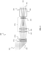
- FIG. 2 shows the optical system 100 of FIG. 1 with further optional features.
- FIG. 2 shows an optical zoom system 100 for a tele-photo miniature zoom camera 600, e.g. as shown in FIG. 6 , according to an embodiment of the invention.
- FIG. 2 shows a number of elements of the optical zoom system 100, which may each comprises one or more parts, and may also comprise parts that are not drawn (in order to give a better overview of the optical system 100).
- the optical zoom system 100 shown in FIG. 2 has a light entrance 202, e.g. an aperture, which is followed by a mirror 201, in particular a folding mirror 201.
- a light entrance 202 e.g. an aperture
- the first lens group 101a and the second lens group 101b are arranged on the optical axis.
- the first lens group 101a may be arranged before the second lens group 101b (as shown), but also in reverse order.
- the lens groups 101a and 101b may be followed by the third lens group 101c (as shown), but the order of the three lens groups 101 on the optical axis 102 may also be different.
- the at least three lens groups 101 are followed by a detector assembly 200 configured to detect light collected by the optical zoom system 100, and configured to capture one or more images based on the detected light.
- the detector assembly 200 may include a spectral separator 500, e.g. an x-cube separator 500 (see FIG. 5 ), and may further comprise a sensor array comprising a plurality of image sensors 501 (see FIG. 5 ) after the separator 500.
- the detector assembly 200 may comprise three image sensors 501.
- the spectral separator 500 may in this case transfer three defined wavelength regions onto the three image sensors 501, in a way that it splits the incoming electromagnetic field (light, but can also be/include electromagnetic radiation invisible to the human eye, e.g.
- the spectral separator 500 is configured to separate the light into a plurality of spectral bands. Then, each image sensor 501 may capture an image in one of these spectral bands.
- each image sensor 501 may detect a spectral band of the incoming/collected light. Special attention should be made to the coating of the spectral separator if realized as x-cube separator 500, in order to meet the spectral bands, and in order to achieve an un-polarized performance (meaning not polarization dependent).
- the moving (first and second) lens groups 101a and 101b may have different zooming functions.
- the second lens group 101b may be moveable by a greater amount, and may primarily drive the optical zoom system magnification.
- the first lens group 101a may be moveable by a smaller amount, and may be used to compensate the optical zoom system 100, in order to achieve a stable focusing/imaging onto the image sensor(s) 501.
- the third lens group 101c may comprise at least two subgroups, e.g. a first subgroup 203 and a second subgroup 204. Optionally, it may also comprise a third subgroup 205.
- the first subgroup 203 and the second subgroup 204 may each have a positive optical power.
- the third subgroup 204 may have negative optical power.
- the first subgroup 203 may be arranged and configured such that it collects light from the second lens group 101b. It may further be configured to provide the collected light, in particular parallel light rays, to the second subgroup 204.
- the second subgroup 204 may be configured to form a real image from the collected light, in particular for being captured by the detector assembly 200.
- light rays associated with a given image point of the real image are substantially parallel between the first subgroup 203 and the second subgroup, i.e. within ⁇ 4°, or even ⁇ 2° from a mean direction of the light rays, e.g. along the optical axis 102.
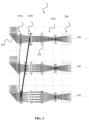
- FIG. 3 shows an optical zoom system 100 as in FIG. 2 , but illustrates a movement of the first lens group 101a and the second lens group 101b, respectively.
- the movement curve of the second lens group 101b (solid line) may be rather big, i.e. it may have a large movement range, while the movement curve of the first lens group 101a (dotted line) may be small, i.e. it may move only very little over a small movement range.
- the second lens group 101b has a negative optical power, while the first lens group 101a has a positive optical power. It can be further seen from Fig. 3 , that the movement of the second lens group 101b may go completely from the first lens group 101a to the third lens group 101c. The first lens group 101a, to the contrary, moves only very little.
- a second, e.g. screw, actuator may be provided to move the second lens group 101b.
- a more precise and/or faster first actuator may move the first lens group 101a, which first actuator could be either a voice coil motor (VCM), or piezo actuator (PA) setup, or a wiggle actuator.
- VCM voice coil motor
- PA piezo actuator
- the combination of such actuators may ensure the necessary precision and response time to achieve image capturing of the optical zoom camera 600 including the optical zoom system 100, particularly in a modem mobile device.
- the first lens group 101a may not only have the task to establish a focal imaging onto the image sensor(s) 501, but may also achieves an optimum near-imaging through its motion. Further, due to the fact that it can be fitted with a fast and/or precise actuator, it is also possible to give the first lens group 101a an auto-focus function, for example, within an optical zoom camera 600.
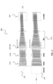
- FIG. 4 shows an even more detailed picture of the optical zoom system 100, in particular, from the side and the top.
- the lens groups 101 may each include two or more lens elements to for the lens group 101.
- These lens elements may have an elliptical optical cross section, which enables more light to enter the optical zoom system 100, and therefore decreases the effective F-Number.
- the lens elements may have an i-cut cross section, which provides another possibility to decrease the F-Number.
- each lens group 101 may comprises one or more lenses having an elliptical cross section or an i-cut cross section.
- the optical zoom system 100 is more sensitive to an angular tilt of the incoming light or ray field. Therefore, OIS may be done upfront, e.g. using the mirror 201 shown in FIG. 2 as an OIS device.
- the mirror 201 may be configured to tilt about two axes. By tilting the mirror 201 in two directions, the incoming light / ray field can be stabilized, and can further be properly redirected (e.g. folded) for propagation through the at least three lens groups 101, and further onto the image sensor(s) 501.
- the zoom camera 600 may be provided with an additional degree of freedom, because the three sensors 501 do not necessarily have to have the same distance from the spectral separator 500 (e.g. x-cube separator).
- the spectral separator 500 e.g. x-cube separator
- each image sensor 501, and therefore each spectral band may have its own optimized working distance behind the spectral separator 500, and therefore behind the fixed third lens group 101c.
- FIG. 6 shows a mobile device 601, which includes a zoom camera 600 according to an embodiment of the invention.
- the mobile device 601 may be a mobile phone, particularly a smartphone, but may also be a tablet, laptop, smartwatch or similar device.
- the zoom camera 600 comprises the optical zoom system 100 described above with respect to FIG. 1 - 5 , and comprises one or more image sensors 501.
- Each image sensor 501 may have a sensor surface configured to capture an image based on light collected by the optical zoom system 100.
- FIG. 1 shows a mobile phone, particularly a smartphone, but may also be a tablet, laptop, smartwatch or similar device.
- the zoom camera 600 comprises the optical zoom system 100 described above with respect to FIG. 1 - 5 , and comprises one or more image sensors 501.
- Each image sensor 501 may have a sensor surface configured to capture an image based on light collected by the optical zoom system 100.
- the zoom camera may further comprise the spectral separator 500 - wherein the spectral separator 500 and the image sensor(s) 501 form a detector assembly 200 - and the spectral separator 500 may be configured to separate light collected by the optical zoom system 100 into a plurality of spectral bands, e.g. into three bands like R, G, and B.
- Each image sensor 501 may be configured to capture an image in one of the spectral bands.
Landscapes
- Physics & Mathematics (AREA)
- General Physics & Mathematics (AREA)
- Optics & Photonics (AREA)
- Engineering & Computer Science (AREA)
- Signal Processing (AREA)
- Multimedia (AREA)
- Nonlinear Science (AREA)
- Human Computer Interaction (AREA)
- Spectroscopy & Molecular Physics (AREA)
- Lens Barrels (AREA)
- Studio Devices (AREA)
- Lenses (AREA)
Description
- The present invention relates to the field of cameras for mobile devices, in particular optical zoom cameras. The invention proposes an optical zoom system for such an optical zoom camera and the optical zoom camera, which are suitable for modern mobile devices, for instance, smartphones.
- Recently there has been a tendency to supply imaging devices in mobile devices, e.g. mobile phones, with two or even three different fixed focal length cameras, in order to record still or moving pictures with different image magnifications. For each magnification, a dedicated camera is provided. Since, however, the available volume in mobile phones is limited, the number of cameras is limited, too.
- Moreover, especially for imaging with tele-photo magnification, it is difficult to implement the cameras inside a thin housing of e.g. a smartphone. Until now, only magnifications of up to M2x and M3x have been demonstrated to be compatible with modem mobile device thicknesses.
- An alternative to the above-mentioned fixed focal length cameras would be optical zoom cameras. Optical zoom cameras for mobile devices are typically folded, using mirrors or prisms, so that the optical zoom system (zoom optics) can extend along the longest dimension of the mobile device (e.g. smartphone). However, up to now, such folded optical zoom cameras use a lens concept that makes them rather bulky, and it may be impossible to implement them in thinner future smartphones. One example of a mobile phone with a folded optical zoom camera is the Asus ZenPhone, which requires an extra thick middle section.
- The optical zoom systems usually involve movements of all their lens groups, to simultaneously shift the optics over a large mechanical range, in order to form an image on an image sensor. These movements involve shifting of all variable lenses at all times, so as to keep the image plane stable. This results in long and bulky optics. Further, it imposes significant restraints and tight tolerances on actuator movement that drives the lenses or lens groups, in order to achieve a precise simultaneous positioning.
- Because of the above-described lack of compatibility with modern mobile devices, particularly smartphones, the implementation of tele-photo optical zoom systems has been abandoned.
- RUDOLF KINGSLAKE: "The Development of the Zoom Lens", Journal of the SMTPE, vol. 69, August 1960, pages 534-544 discloses various types of zoom lenses.
-
US 2016/044232 A1 discloses a camera module comprising a first lens unit having a plurality of lenses configured to focus light, a second lens unit configured to magnify an image formed by light passing through the first lens unit and a moving unit connected to the first lens unit and the second lens unit and configured to move at least one of the first lens unit and the second lens unit in order to adjust the distance between the first lens unit and the second lens unit. - In view of the above, embodiments of the present invention aim at providing improved optical zoom cameras for mobile device. An objective is to provide an optical zoom system for an optical zoom camera that is compatible with modem mobile device, particularly smartphone, thickness. The optical zoom system should accordingly allow making the optical zoom camera, and by consequence the mobile device, less bulky, in particular thinner. Another goal is to provide a tele-photo optical zoom camera with an optical zoom that is precise over a long tele-photo range.
- The objective is achieved by the embodiments of the invention as described in the enclosed independent claims. Advantageous implementations of the embodiments of the invention are further defined in the dependent claims. The invention is defined in the independent claims. Advantageous features are defined in the dependent claims.
- In particular, embodiments of the invention propose a new optical zoom system design for an optical zoom camera compatible with modern smartphones.
- A first aspect of the invention provides an optical zoom system for a mobile according to claim 1.
- The at least three spatially separated lens groups comprise, in particular, all lens groups of the optical zoom system. The optical zoom system of the first aspect benefits from the dedication and separation of the optical zooming function to different lens groups. The resulting optical design of the optical zoom system becomes more compact as a consequence, and thus suitable for an optical zoom camera in a modem mobile device, e.g. smartphone. The optical zoom system may have as few as three lens groups (wherein two of the lens groups are movable, and one lens group is fixed/immovable). A zooming function that sets the magnification of the optical zoom system can be performed with the second lens group, and a zooming function that focuses the optical zoom system can be performed with the first lens group. The third, fixed lens group, can provide the collected light onto an image sensor of an optical zoom camera.
- In an embodiment, the second lens group is movable over a greater distance along the optical axis than the first lens group That is, the first lens group may use a larger travel distance, while the second lens group may vary less, e.g. only a little. Since the zooming functions are divided between the first lens group and the second lens group, only one lens group has to be moved at a time. For example, the magnification may be set as intended by moving the second lens group, and then the adjustment for the focusing of the optical system may be made by moving the second lens group. An optical macro function may also be achieved using the first lens group. However, the first lens group and the second lens group may also move simultaneously.
- In an implementation form of the first aspect, each lens group, except the first and the second lens group, is immovable along the optical axis.
- That means, the first lens group and the second lens group are the only movable lens groups of the optical zoom system. Thus, the lens groups that have to be moved is kept at a minimum.
- In an implementation form of the first aspect, the first and/or the second lens group is continuously movable along the optical axis.
- Thus, the magnification and/or focus of the optical zoom system can be adjusted precisely.
- In an implementation form of the first aspect, each lens group is assigned a separate space in the optical zoom system, which is not used and/or usable by any other lens group.
- The optical design of the optical zoom is thus optimized, in that there is no mechanical overlap between e.g. actuator ranges of both movable lens groups.
- In an implementation form of the first aspect, the second lens group and the first lens group are separately and/or independently movable.
- The optical zoom system can be build more compact and less complex as a consequence.
- In an implementation form of the first aspect, the second lens group is movable between the third lens group and the first lens group.
- In an implementation form of the first aspect, the optical zoom system further comprises: a second actuator configured to move the second lens group, and a first actuator configured to move the first lens group.
- That is, the optical zoom system can be controlled, e.g. by a control device of an optical zoom camera or mobile device including the optical zoom system, to move the first lens group and second lens group independently.
- In an embodiment, the first actuator is configured to move the second lens group more accurately and/or faster than the second actuator is configured to move the first lens group.
- In particular, this is beneficial if the second lens group is movable over a larger spatial range than the first lens group. The second lens group can be moved roughly to set the magnification, and the first lens group can be moved accurately to focus precisely. Since the first lens group may be involved in an autofocus operation, moving the first lens group faster provides high autofocusing speed.
- In an implementation form of the first aspect, the first actuator includes a voice coil actuator or a piezoelectric actuator, and/or the second actuator includes a screw actuator.
- In an implementation form of the first aspect, each lens group comprises one or more lenses having an elliptical cross section or an i-cut cross section.
- Such cross-section optimized lenses or lens groups, or lens barrels, decreases the F-Number of the optical zoom system, thus enables more light to enter the optical zoom system, and thus enables higher Modulation Transfer Function (MTF) values. Low light operation of the zoom camera is enabled.
- In an implementation form of the first aspect, the optical zoom system further comprises an optical image stabilization (OIS)system.
- The OIS may involve moving one or more of the lens groups perpendicularly to the optical axis. In one embodiment, the OIS system comprises a tiltable mirror, which may also be configured to fold incident light (entering the optical zoom system) towards the at least three lens groups, i.e. onto the optical axis. In an embodiment, the mirror is configured to tilt about two axes.
- In an implementation form of the first aspect, the first lens group is arranged before the second lens group, and the second lens group is arranged before the third lens group, with respect to a light capturing direction of the optical zoom system.
- The light capturing direction corresponds, in particular, to a propagation direction of light, which is collected by the optical zoom system, i.e. usually parallel to the optical axis.
- In an implementation form of the first aspect, the second lens group has a negative optical power, and the first lens group has a positive optical power.
- In an implementation form of the first aspect, the third lens group comprises two subgroups arranged on the optical axis, the two subgroups comprising: a first subgroup for collecting light from the second lens group, and a second subgroup for forming a real image from the collected light, the first and the second subgroup each having a positive optical power, wherein light rays associated with one image point of the real image are substantially parallel between the first subgroup and the second subgroup.
- In particular, "substantially parallel" means within ±4° from a mean direction of these light rays, e.g. the optical axis, particularly ±2° from the mean direction.
- A second aspect of the invention provides a zoom camera for a mobile device, the zoom camera comprising: the optical zoom system according to the first aspect or any of its implementation forms, and one or more image sensors, each image sensor having a sensor surface for capturing an image based on light collected by the optical zoom system.
- The optical zoom camera of the second aspect enjoys all advantages described above for the optical zoom system of the first aspect. In particular, the zoom camera can be build smaller, and enables thinner mobile devices, particularly smartphones.
- In an implementation form of the second aspect, the zoom camera further comprises: a spectral separator configured to separate the light into a plurality of spectral bands, wherein each of the image sensors is configured to capture an image in one of the spectral bands.
- In addition to the optical zoom system, this multi sensor image capturing scheme beneficially enhances the light sensitivity of the zoom camera, and enables multi-color or Infrared Radiation (IR) imaging.
- In an implementation form of the second aspect, the zoom camera is configured to move the first lens group in an autofocus mode.
- Since the first lens group may move only over a shorter spatial range in the optical zoom system, and may be driven by a fast and precise actuator, the autofocus operation of the zoom camera is quick and accurate.
- In summary, the aspects and implementation forms described above achieve a high quality zoom camera that is capable of taking pictures or video content with a variable magnification, while it can be adjusted over a wide tele-photo range (up to M10x) and is capable to be implemented into a modern smartphone. The zoom camera benefits from the optical zoom system, which overcomes the necessity to move all lens groups simultaneously, and achieves a much smaller system length. In particular, by dedicating optical zoom functions to different optical parts (lens groups) allows a more compact design. In contrast to other optical zoom systems, only one lens group has to be moved at a time, and no cross- movement is necessary. Furthermore, stability and actuator application are improved, and design space conflicts are avoided, because the available space is used more efficiently.
- It has to be noted that all devices, elements, units and means described in the present application could be implemented in the software or hardware elements or any kind of combination thereof. All steps which are performed by the various entities described in the present application as well as the functionalities described to be performed by the various entities are intended to mean that the respective entity is adapted to or configured to perform the respective steps and functionalities. Even if, in the following description of specific embodiments, a specific functionality or step to be performed by external entities is not reflected in the description of a specific detailed element of that entity which performs that specific step or functionality, it should be clear for a skilled person that these methods and functionalities can be implemented in respective software or hardware elements, or any kind of combination thereof. The scope of the invention is set by the appended claims.
- The above described aspects and implementation forms of the present invention will be explained in the following description of example embodiments in relation to the enclosed drawings, in which
- FIG. 1
- shows an optical zoom system according to an embodiment of the invention.
- FIG. 2
- shows an optical zoom system according to an embodiment of the invention.
- FIG. 3
- shows an optical zoom system according to an embodiment of the invention
- FIG. 4
- shows an optical zoom system according to an embodiment of the invention
- FIG. 5
- shows a spectral separator for a zoom camera according to an embodiment of the invention.
- FIG. 6
- shows a zoom camera according to an embodiment of the invention in a mobile device.
-
FIG. 1 shows anoptical zoom system 100 according to an example of an embodiment of the invention. Theoptical zoom system 100 is suitable for an optical zoom camera, as e.g. thezoom camera 600 shown inFIG. 6 , and is in particular suitable for being used in amobile device 601, which may be equipped with thezoom camera 600. Theoptical zoom system 100 beneficially allows building thezoom camera 600 more compact than with previous concepts, and thus also allows designingmobile device 601 thinner in the future. Theoptical zoom system 100 also enables a higher magnification, i.e. into the longer tele-phot range, than with previous concepts. - The
optical zoom system 100 to this end comprises at least three spatially separated lens groups 101, which are arranged on an optical axis 102 (indicated by the dashed line). Notably, theoptical zoom system 100 does not include any further lens groups, than the at least three lens groups 101, on theoptical axis 102. Theoptical zoom system 100 may, for example, include exactly three lens groups 101 on theoptical axis 102, as exemplarily illustrated inFIG. 1 . - Of the at least three lens groups 101 of the
optical zoom system 100, at least athird lens group 101c is immovable along theoptical axis 102. Theoptical system 100 may, however, comprise further immovable lens groups 101 on theoptical axis 102. - Furthermore, a
second lens group 101b and afirst lens group 101a of theoptical system 100 are movable along theoptical axis 102. Thefirst lens group 101a and thesecond lens group 101b are, in particular, the only lens groups 101 of the at least three lens groups 101 on theoptical axis 102, which are movable. In other words, each lens group 101, except thefirst lens group 101a and thesecond lens group 101b, is immovable along theoptical axis 102. Thereby, thesecond lens group 101b is movable along theoptical axis 102, in order to set a magnification of theoptical zoom system 100, and thefirst lens group 101a is movable along theoptical axis 102, in order to focus the optical zoom system. Thefirst lens group 101a and/or thesecond lens group 101b may be continuously movable along theoptical axis 102 over their respective ranges of movement. The movement ranges of thefirst lens group 101a and thesecond lens group 101b may be different, in particular thesecond lens group 101b may have a larger movement range. Additionally or alternatively, thefirst lens group 101a and thesecond lens group 101b may be separately and/or independently movable. That is, each of the twolens groups - In the
optical zoom system 100, each of the at least three lens groups 101 may be assigned a separate/dedicated space, which is not used and/or is not usable by any other lens group 101. That is, for example, no lens of one lens group 101 may be arranged within/between lenses of another lens group 101. Moreover, thefirst lens group 101a and thesecond lens group 101b, respectively, may not be movable to move into the space occupied by / dedicated to another lens group 101. For instance, thesecond lens group 101b may be movable between thethird lens group 101c and thefirst lens group 101a, however, it cannot be moved into the spaces assigned to thethird lens group 101c and thefirst lens group 101a, respectively. -
Fig. 2 shows theoptical system 100 ofFIG. 1 with further optional features. In particularFIG. 2 shows anoptical zoom system 100 for a tele-photominiature zoom camera 600, e.g. as shown inFIG. 6 , according to an embodiment of the invention.FIG. 2 shows a number of elements of theoptical zoom system 100, which may each comprises one or more parts, and may also comprise parts that are not drawn (in order to give a better overview of the optical system 100). - In particular, the
optical zoom system 100 shown inFIG. 2 has alight entrance 202, e.g. an aperture, which is followed by amirror 201, in particular afolding mirror 201. Behind themirror 201, thefirst lens group 101a and thesecond lens group 101b are arranged on the optical axis. Thereby, thefirst lens group 101a may be arranged before thesecond lens group 101b (as shown), but also in reverse order. Thelens groups third lens group 101c (as shown), but the order of the three lens groups 101 on theoptical axis 102 may also be different. - The at least three lens groups 101 are followed by a
detector assembly 200 configured to detect light collected by theoptical zoom system 100, and configured to capture one or more images based on the detected light. Thedetector assembly 200 may include aspectral separator 500, e.g. an x-cube separator 500 (seeFIG. 5 ), and may further comprise a sensor array comprising a plurality of image sensors 501 (seeFIG. 5 ) after theseparator 500. For instance, thedetector assembly 200 may comprise threeimage sensors 501. Thespectral separator 500 may in this case transfer three defined wavelength regions onto the threeimage sensors 501, in a way that it splits the incoming electromagnetic field (light, but can also be/include electromagnetic radiation invisible to the human eye, e.g. IR) at certain spectral bands (which may be confined to an implemented glass or plastic lens materials of theoptical zoom system 100 and its lateral color aberration). In other words, thespectral separator 500 is configured to separate the light into a plurality of spectral bands. Then, eachimage sensor 501 may capture an image in one of these spectral bands. - After the color separation by the separator 500 (e.g. into Red (R), Green (G), and Blue (B)), each
image sensor 501 may detect a spectral band of the incoming/collected light. Special attention should be made to the coating of the spectral separator if realized asx-cube separator 500, in order to meet the spectral bands, and in order to achieve an un-polarized performance (meaning not polarization dependent). - The moving (first and second)
lens groups second lens group 101b may be moveable by a greater amount, and may primarily drive the optical zoom system magnification. Thefirst lens group 101a may be moveable by a smaller amount, and may be used to compensate theoptical zoom system 100, in order to achieve a stable focusing/imaging onto the image sensor(s) 501. - The
third lens group 101c may comprise at least two subgroups, e.g. afirst subgroup 203 and asecond subgroup 204. Optionally, it may also comprise athird subgroup 205. Thefirst subgroup 203 and thesecond subgroup 204 may each have a positive optical power. Thethird subgroup 204 may have negative optical power. Thefirst subgroup 203 may be arranged and configured such that it collects light from thesecond lens group 101b. It may further be configured to provide the collected light, in particular parallel light rays, to thesecond subgroup 204. Thesecond subgroup 204 may be configured to form a real image from the collected light, in particular for being captured by thedetector assembly 200. Thereby, light rays associated with a given image point of the real image are substantially parallel between thefirst subgroup 203 and the second subgroup, i.e. within ±4°, or even ±2° from a mean direction of the light rays, e.g. along theoptical axis 102. -
FIG. 3 shows anoptical zoom system 100 as inFIG. 2 , but illustrates a movement of thefirst lens group 101a and thesecond lens group 101b, respectively. As can be seen, the movement of the twolens groups second lens group 101b (solid line) may be rather big, i.e. it may have a large movement range, while the movement curve of thefirst lens group 101a (dotted line) may be small, i.e. it may move only very little over a small movement range. - In this
optical zoom system 100 ofFIG. 3 , thesecond lens group 101b has a negative optical power, while thefirst lens group 101a has a positive optical power. It can be further seen fromFig. 3 , that the movement of thesecond lens group 101b may go completely from thefirst lens group 101a to thethird lens group 101c. Thefirst lens group 101a, to the contrary, moves only very little. - With respect to the mechanical possibilities for moving the
different lens groups second lens group 101b. Further, a more precise and/or faster first actuator may move thefirst lens group 101a, which first actuator could be either a voice coil motor (VCM), or piezo actuator (PA) setup, or a wiggle actuator. The combination of such actuators may ensure the necessary precision and response time to achieve image capturing of theoptical zoom camera 600 including theoptical zoom system 100, particularly in a modem mobile device. - Due to the special layout of the
optical zoom system 100, as shown inFIG. 1 - 3 , thefirst lens group 101a may not only have the task to establish a focal imaging onto the image sensor(s) 501, but may also achieves an optimum near-imaging through its motion. Further, due to the fact that it can be fitted with a fast and/or precise actuator, it is also possible to give thefirst lens group 101a an auto-focus function, for example, within anoptical zoom camera 600. -
FIG. 4 shows an even more detailed picture of theoptical zoom system 100, in particular, from the side and the top. It can be seen, that the lens groups 101 (movablefirst lens group 101a / movablesecond lens group 101b / fixedthird lens group 101c) may each include two or more lens elements to for the lens group 101. These lens elements may have an elliptical optical cross section, which enables more light to enter theoptical zoom system 100, and therefore decreases the effective F-Number. Alternatively or in combination, the lens elements may have an i-cut cross section, which provides another possibility to decrease the F-Number. Generally, each lens group 101 may comprises one or more lenses having an elliptical cross section or an i-cut cross section. - Due to the desired high magnification, the
optical zoom system 100 is more sensitive to an angular tilt of the incoming light or ray field. Therefore, OIS may be done upfront, e.g. using themirror 201 shown inFIG. 2 as an OIS device. In this case, themirror 201 may be configured to tilt about two axes. By tilting themirror 201 in two directions, the incoming light / ray field can be stabilized, and can further be properly redirected (e.g. folded) for propagation through the at least three lens groups 101, and further onto the image sensor(s) 501. - By using, as shown in
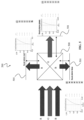
FIG. 5 , a 3-sensor array, i.e. threeoptical image sensors 501, thezoom camera 600 may be provided with an additional degree of freedom, because the threesensors 501 do not necessarily have to have the same distance from the spectral separator 500 (e.g. x-cube separator). Thus, eachimage sensor 501, and therefore each spectral band, may have its own optimized working distance behind thespectral separator 500, and therefore behind the fixedthird lens group 101c. -
FIG. 6 shows amobile device 601, which includes azoom camera 600 according to an embodiment of the invention. Themobile device 601 may be a mobile phone, particularly a smartphone, but may also be a tablet, laptop, smartwatch or similar device. Thezoom camera 600 comprises theoptical zoom system 100 described above with respect toFIG. 1 - 5 , and comprises one ormore image sensors 501. Eachimage sensor 501 may have a sensor surface configured to capture an image based on light collected by theoptical zoom system 100. In particular, as shown inFIG. 5 , the zoom camera may further comprise the spectral separator 500 - wherein thespectral separator 500 and the image sensor(s) 501 form a detector assembly 200 - and thespectral separator 500 may be configured to separate light collected by theoptical zoom system 100 into a plurality of spectral bands, e.g. into three bands like R, G, and B. Eachimage sensor 501 may be configured to capture an image in one of the spectral bands. - The present invention has been described in conjunction with various embodiments as examples as well as implementations. However, other variations can be understood and effected by those persons skilled in the art and practicing the claimed invention, from the studies of the drawings, this disclosure and the independent claims. In the claims as well as in the description the word "comprising" does not exclude other elements or steps and the indefinite article "a" or "an" does not exclude a plurality. A single element or other unit may fulfill the functions of several entities or items recited in the claims. The mere fact that certain measures are recited in the mutual different dependent claims does not indicate that a combination of these measures cannot be used in an advantageous implementation.
Claims (13)
- An optical zoom system (100) for a mobile device (601), the optical zoom system (100) comprising:at least three spatially separated lens groups (101) arranged on an optical axis (102),
wherein the optical zoom system (100) does not include any further lens groups on the optical axis (102), whereina third lens group (101c) is immovable along the optical axis (102),a second lens group (101b) is movable along the optical axis (102) to set a magnification of the optical zoom system (100), anda first lens group (101a) is movable along the optical axis (102) to focus the optical zoom system,the optical zoom system further comprising:a first actuator configured to move the first lens group (101a), anda second actuator configured to move the second lens group (101b),characterized inthat the first actuator is more precise and/or faster than the second actuator. - The optical zoom system (100) according to claim 1, wherein:
each lens group (101), except the first and the second lens group (101a, 101b), is immovable along the optical axis (102). - The optical zoom system (100) according to claim 1 or 2, wherein:
the first and/or the second lens group (101a, 101b) is continuously movable along the optical axis (102). - The optical zoom system (100) according to one of the claims 1 to 3, wherein:
each lens group (101) is assigned a separate space in the optical zoom system (100), which is not used and/or usable by any other lens group (101). - The optical zoom system (100) according to one of the claims 1 to 4, wherein:
the second lens group (101b) and the first lens group (101a) are separately and/or independently movable. - The optical zoom system (100) according to one of the claims 1 to 5, wherein:
the second lens group (101b) is movable between the third lens group (101c) and the first lens group (101a). - The optical zoom system (100) according to one of the claims 1 to 6, wherein:the first actuator includes a voice coil actuator or a piezoelectric actuator, and/orthe second actuator includes a screw actuator.
- The optical zoom system (100) according to one of the claims 1 to 7, wherein:
each lens group (101) comprises one or more lenses having an elliptical cross section or an i-cut cross section. - The optical zoom system (100) according to one of the claims 1 to 8, further comprising:
an optical image stabilization system. - The optical zoom system (100) according to one of the claims 1 to 9, wherein:
the first lens group is arranged before the second lens group, and the second lens group is arranged before the third lens group, with respect to a light collecting direction of the optical zoom system. - The optical zoom system (100) according to one of the claims 1 to 10, wherein:the second lens group (101b) has a negative optical power, andthe first lens group (101a) has a positive optical power.
- The optical zoom system (100) according to any one of the claims 1 to 11, wherein the third lens group (101c) comprises two subgroups arranged on the optical axis (102), the two subgroups comprising:a first subgroup (203) for collecting light from the second lens group (101b), anda second subgroup (204) for forming a real image from the collected light,the first and the second subgroup (203, 204) each having a positive optical power,wherein light rays associated with one image point of the real image are substantially parallel between the first subgroup (203) and the second subgroup (204).
- A zoom camera (600) for a mobile device (601), the zoom camera (600) comprising:the optical zoom system (100) according to any one of the claims 1 to 12, andone or more image sensors (501), each image sensor (501) having a sensor surface for capturing an image based on light collected by the optical zoom system (100).
Applications Claiming Priority (1)
| Application Number | Priority Date | Filing Date | Title |
|---|---|---|---|
| PCT/EP2019/063347 WO2020233816A1 (en) | 2019-05-23 | 2019-05-23 | Optical zoom system and camera for a mobile device |
Publications (2)
| Publication Number | Publication Date |
|---|---|
| EP3966618A1 EP3966618A1 (en) | 2022-03-16 |
| EP3966618B1 true EP3966618B1 (en) | 2025-03-26 |
Family
ID=66668905
Family Applications (1)
| Application Number | Title | Priority Date | Filing Date |
|---|---|---|---|
| EP19726954.1A Active EP3966618B1 (en) | 2019-05-23 | 2019-05-23 | Optical zoom system and camera for a mobile device |
Country Status (4)
| Country | Link |
|---|---|
| US (1) | US12368959B2 (en) |
| EP (1) | EP3966618B1 (en) |
| CN (1) | CN113826036B (en) |
| WO (1) | WO2020233816A1 (en) |
Family Cites Families (18)
| Publication number | Priority date | Publication date | Assignee | Title |
|---|---|---|---|---|
| US3848967A (en) * | 1972-12-26 | 1974-11-19 | Polaroid Corp | Compact seven element zoom lens with optical compensation |
| JP2005292403A (en) * | 2004-03-31 | 2005-10-20 | Konica Minolta Opto Inc | Magnification optical system, imaging lens device, and digital device |
| US7388613B2 (en) * | 2004-07-02 | 2008-06-17 | Flextronics International Usa, Inc. | Pop up prism lens assembly |
| JP4892831B2 (en) * | 2004-12-10 | 2012-03-07 | カシオ計算機株式会社 | Camera device and lens control method |
| JP5109232B2 (en) * | 2005-03-15 | 2012-12-26 | 株式会社ニコン | Lens barrel |
| US7859764B2 (en) * | 2006-12-20 | 2010-12-28 | Konica Minolta Opto, Inc. | Variable-power optical system, image pickup device, and digital apparatus |
| KR101495540B1 (en) * | 2009-03-13 | 2015-02-25 | 삼성전자주식회사 | Telephoto lens system and photographing device having the same |
| WO2012077257A1 (en) * | 2010-12-06 | 2012-06-14 | パナソニック株式会社 | Lens barrel, imaging device and camera |
| US8988564B2 (en) * | 2011-09-09 | 2015-03-24 | Apple Inc. | Digital camera with light splitter |
| DE102012005938B4 (en) * | 2012-03-26 | 2021-05-12 | Carl Zeiss Optronics Gmbh | Multispectral zoom lens and camera system |
| JP2014179736A (en) * | 2013-03-14 | 2014-09-25 | Toshiba Corp | Camera module |
| JP6237106B2 (en) * | 2013-10-18 | 2017-11-29 | コニカミノルタ株式会社 | Zoom lens and imaging device |
| CN110058391B (en) * | 2014-04-21 | 2021-11-23 | 株式会社尼康 | Variable magnification optical system and optical apparatus |
| CN106716215B (en) * | 2014-07-30 | 2019-08-13 | 株式会社尼康 | Zoom optical system and optical device |
| KR102187571B1 (en) * | 2014-08-11 | 2020-12-07 | 엘지전자 주식회사 | Mobile terminal |
| US10139601B2 (en) | 2015-05-08 | 2018-11-27 | Samsung Electronics Co., Ltd. | Thin telephoto lens and image pickup apparatus including the same |
| JP6899630B2 (en) | 2016-02-02 | 2021-07-07 | ソニーグループ株式会社 | Interchangeable lenses and drive methods, as well as electronic devices |
| KR102067069B1 (en) * | 2017-06-16 | 2020-01-16 | 삼성전기주식회사 | Camera module |
-
2019
- 2019-05-23 WO PCT/EP2019/063347 patent/WO2020233816A1/en not_active Ceased
- 2019-05-23 EP EP19726954.1A patent/EP3966618B1/en active Active
- 2019-05-23 CN CN201980096479.4A patent/CN113826036B/en active Active
-
2021
- 2021-11-22 US US17/532,162 patent/US12368959B2/en active Active
Also Published As
| Publication number | Publication date |
|---|---|
| WO2020233816A1 (en) | 2020-11-26 |
| CN113826036B (en) | 2023-07-18 |
| US12368959B2 (en) | 2025-07-22 |
| CN113826036A (en) | 2021-12-21 |
| US20220086353A1 (en) | 2022-03-17 |
| EP3966618A1 (en) | 2022-03-16 |
Similar Documents
| Publication | Publication Date | Title |
|---|---|---|
| US8325265B2 (en) | Camera module having extended depth of focus mode and autofocus mode and method of operating the same | |
| US7667897B2 (en) | Dual lens optical system and dual lens camera having the same | |
| US10359608B2 (en) | Bifocal lens and imaging device including same | |
| KR101720770B1 (en) | Lens Optical System and Digital Camera Module Comprising the Same | |
| US7889435B2 (en) | Imaging device having a dual lens optical system | |
| JP2009036844A (en) | Zoom lens and photographing system having the same | |
| KR102861661B1 (en) | Camera for portable electronic devices with optical image stabilization | |
| US8662762B2 (en) | Compact lens optical system and digital camera module including the same | |
| KR20230003582A (en) | Optical lenses, lens modules and terminals | |
| KR102779249B1 (en) | Folded macro-tele camera lens designs | |
| JP2013047731A (en) | Barrel and imaging apparatus | |
| CN116449539B (en) | Image capturing system assembly, image acquisition device and electronic device | |
| US12368959B2 (en) | Optical zoom system and camera for a mobile device | |
| US6975358B1 (en) | Dual channel imaging device | |
| KR101720188B1 (en) | Compact Lens Optical System and Digital Camera Module Comprising the Same | |
| KR20160113893A (en) | Single focus lens and photographing lens having the same | |
| TW201329504A (en) | Telephoto zoom lens | |
| KR20110056864A (en) | Dual lens optical system and digital camera module having same | |
| CN121596523A (en) | Image capturing optical lens assembly, image capturing device and electronic device | |
| CN121596522A (en) | Image pickup lens system, image pickup device and electronic device | |
| US20250298220A1 (en) | Image capturing optical system, imaging apparatus and electronic device | |
| TW202609388A (en) | Imaging optical lens assembly, image capturing unit and electronic device | |
| CN120010090A (en) | Optical camera lens assembly, imaging device and electronic device | |
| CN117806010A (en) | Image system lens group, image capturing device and electronic device | |
| CN120315148A (en) | Camera lens assembly, imaging device and electronic device |
Legal Events
| Date | Code | Title | Description |
|---|---|---|---|
| STAA | Information on the status of an ep patent application or granted ep patent |
Free format text: STATUS: THE INTERNATIONAL PUBLICATION HAS BEEN MADE |
|
| PUAI | Public reference made under article 153(3) epc to a published international application that has entered the european phase |
Free format text: ORIGINAL CODE: 0009012 |
|
| STAA | Information on the status of an ep patent application or granted ep patent |
Free format text: STATUS: REQUEST FOR EXAMINATION WAS MADE |
|
| 17P | Request for examination filed |
Effective date: 20211207 |
|
| AK | Designated contracting states |
Kind code of ref document: A1 Designated state(s): AL AT BE BG CH CY CZ DE DK EE ES FI FR GB GR HR HU IE IS IT LI LT LU LV MC MK MT NL NO PL PT RO RS SE SI SK SM TR |
|
| DAV | Request for validation of the european patent (deleted) | ||
| DAX | Request for extension of the european patent (deleted) | ||
| REG | Reference to a national code |
Ref country code: DE Ref legal event code: R079 Free format text: PREVIOUS MAIN CLASS: G02B0009140000 Ipc: G02B0027100000 Ref document number: 602019067755 Country of ref document: DE |
|
| GRAP | Despatch of communication of intention to grant a patent |
Free format text: ORIGINAL CODE: EPIDOSNIGR1 |
|
| STAA | Information on the status of an ep patent application or granted ep patent |
Free format text: STATUS: GRANT OF PATENT IS INTENDED |
|
| INTG | Intention to grant announced |
Effective date: 20241125 |
|
| RIC1 | Information provided on ipc code assigned before grant |
Ipc: G02B 15/14 20060101ALI20241115BHEP Ipc: G02B 27/14 20060101ALI20241115BHEP Ipc: G02B 27/10 20060101AFI20241115BHEP |
|
| GRAS | Grant fee paid |
Free format text: ORIGINAL CODE: EPIDOSNIGR3 |
|
| GRAA | (expected) grant |
Free format text: ORIGINAL CODE: 0009210 |
|
| STAA | Information on the status of an ep patent application or granted ep patent |
Free format text: STATUS: THE PATENT HAS BEEN GRANTED |
|
| AK | Designated contracting states |
Kind code of ref document: B1 Designated state(s): AL AT BE BG CH CY CZ DE DK EE ES FI FR GB GR HR HU IE IS IT LI LT LU LV MC MK MT NL NO PL PT RO RS SE SI SK SM TR |
|
| REG | Reference to a national code |
Ref country code: GB Ref legal event code: FG4D |
|
| REG | Reference to a national code |
Ref country code: CH Ref legal event code: EP |
|
| REG | Reference to a national code |
Ref country code: DE Ref legal event code: R096 Ref document number: 602019067755 Country of ref document: DE |
|
| REG | Reference to a national code |
Ref country code: IE Ref legal event code: FG4D |
|
| PGFP | Annual fee paid to national office [announced via postgrant information from national office to epo] |
Ref country code: NL Payment date: 20250421 Year of fee payment: 7 |
|
| REG | Reference to a national code |
Ref country code: NL Ref legal event code: FP |
|
| PG25 | Lapsed in a contracting state [announced via postgrant information from national office to epo] |
Ref country code: RS Free format text: LAPSE BECAUSE OF FAILURE TO SUBMIT A TRANSLATION OF THE DESCRIPTION OR TO PAY THE FEE WITHIN THE PRESCRIBED TIME-LIMIT Effective date: 20250626 |
|
| PG25 | Lapsed in a contracting state [announced via postgrant information from national office to epo] |
Ref country code: FI Free format text: LAPSE BECAUSE OF FAILURE TO SUBMIT A TRANSLATION OF THE DESCRIPTION OR TO PAY THE FEE WITHIN THE PRESCRIBED TIME-LIMIT Effective date: 20250326 |
|
| PGFP | Annual fee paid to national office [announced via postgrant information from national office to epo] |
Ref country code: DE Payment date: 20250408 Year of fee payment: 7 |
|
| PGFP | Annual fee paid to national office [announced via postgrant information from national office to epo] |
Ref country code: GB Payment date: 20250410 Year of fee payment: 7 |
|
| REG | Reference to a national code |
Ref country code: LT Ref legal event code: MG9D |
|
| PG25 | Lapsed in a contracting state [announced via postgrant information from national office to epo] |
Ref country code: NO Free format text: LAPSE BECAUSE OF FAILURE TO SUBMIT A TRANSLATION OF THE DESCRIPTION OR TO PAY THE FEE WITHIN THE PRESCRIBED TIME-LIMIT Effective date: 20250626 |
|
| PG25 | Lapsed in a contracting state [announced via postgrant information from national office to epo] |
Ref country code: HR Free format text: LAPSE BECAUSE OF FAILURE TO SUBMIT A TRANSLATION OF THE DESCRIPTION OR TO PAY THE FEE WITHIN THE PRESCRIBED TIME-LIMIT Effective date: 20250326 |
|
| PG25 | Lapsed in a contracting state [announced via postgrant information from national office to epo] |
Ref country code: LV Free format text: LAPSE BECAUSE OF FAILURE TO SUBMIT A TRANSLATION OF THE DESCRIPTION OR TO PAY THE FEE WITHIN THE PRESCRIBED TIME-LIMIT Effective date: 20250326 |
|
| PG25 | Lapsed in a contracting state [announced via postgrant information from national office to epo] |
Ref country code: GR Free format text: LAPSE BECAUSE OF FAILURE TO SUBMIT A TRANSLATION OF THE DESCRIPTION OR TO PAY THE FEE WITHIN THE PRESCRIBED TIME-LIMIT Effective date: 20250627 Ref country code: BG Free format text: LAPSE BECAUSE OF FAILURE TO SUBMIT A TRANSLATION OF THE DESCRIPTION OR TO PAY THE FEE WITHIN THE PRESCRIBED TIME-LIMIT Effective date: 20250326 |
|
| PG25 | Lapsed in a contracting state [announced via postgrant information from national office to epo] |
Ref country code: SE Free format text: LAPSE BECAUSE OF FAILURE TO SUBMIT A TRANSLATION OF THE DESCRIPTION OR TO PAY THE FEE WITHIN THE PRESCRIBED TIME-LIMIT Effective date: 20250326 |
|
| REG | Reference to a national code |
Ref country code: AT Ref legal event code: MK05 Ref document number: 1779503 Country of ref document: AT Kind code of ref document: T Effective date: 20250326 |
|
| PG25 | Lapsed in a contracting state [announced via postgrant information from national office to epo] |
Ref country code: SM Free format text: LAPSE BECAUSE OF FAILURE TO SUBMIT A TRANSLATION OF THE DESCRIPTION OR TO PAY THE FEE WITHIN THE PRESCRIBED TIME-LIMIT Effective date: 20250326 |
|
| PG25 | Lapsed in a contracting state [announced via postgrant information from national office to epo] |
Ref country code: ES Free format text: LAPSE BECAUSE OF FAILURE TO SUBMIT A TRANSLATION OF THE DESCRIPTION OR TO PAY THE FEE WITHIN THE PRESCRIBED TIME-LIMIT Effective date: 20250326 Ref country code: PT Free format text: LAPSE BECAUSE OF FAILURE TO SUBMIT A TRANSLATION OF THE DESCRIPTION OR TO PAY THE FEE WITHIN THE PRESCRIBED TIME-LIMIT Effective date: 20250728 |
|
| PG25 | Lapsed in a contracting state [announced via postgrant information from national office to epo] |
Ref country code: PL Free format text: LAPSE BECAUSE OF FAILURE TO SUBMIT A TRANSLATION OF THE DESCRIPTION OR TO PAY THE FEE WITHIN THE PRESCRIBED TIME-LIMIT Effective date: 20250326 Ref country code: IT Free format text: LAPSE BECAUSE OF FAILURE TO SUBMIT A TRANSLATION OF THE DESCRIPTION OR TO PAY THE FEE WITHIN THE PRESCRIBED TIME-LIMIT Effective date: 20250326 |
|
| PG25 | Lapsed in a contracting state [announced via postgrant information from national office to epo] |
Ref country code: AT Free format text: LAPSE BECAUSE OF FAILURE TO SUBMIT A TRANSLATION OF THE DESCRIPTION OR TO PAY THE FEE WITHIN THE PRESCRIBED TIME-LIMIT Effective date: 20250326 |
|
| PG25 | Lapsed in a contracting state [announced via postgrant information from national office to epo] |
Ref country code: EE Free format text: LAPSE BECAUSE OF FAILURE TO SUBMIT A TRANSLATION OF THE DESCRIPTION OR TO PAY THE FEE WITHIN THE PRESCRIBED TIME-LIMIT Effective date: 20250326 |
|
| PG25 | Lapsed in a contracting state [announced via postgrant information from national office to epo] |
Ref country code: RO Free format text: LAPSE BECAUSE OF FAILURE TO SUBMIT A TRANSLATION OF THE DESCRIPTION OR TO PAY THE FEE WITHIN THE PRESCRIBED TIME-LIMIT Effective date: 20250326 |
|
| PG25 | Lapsed in a contracting state [announced via postgrant information from national office to epo] |
Ref country code: SK Free format text: LAPSE BECAUSE OF FAILURE TO SUBMIT A TRANSLATION OF THE DESCRIPTION OR TO PAY THE FEE WITHIN THE PRESCRIBED TIME-LIMIT Effective date: 20250326 |
|
| PG25 | Lapsed in a contracting state [announced via postgrant information from national office to epo] |
Ref country code: IS Free format text: LAPSE BECAUSE OF FAILURE TO SUBMIT A TRANSLATION OF THE DESCRIPTION OR TO PAY THE FEE WITHIN THE PRESCRIBED TIME-LIMIT Effective date: 20250726 |
|
| REG | Reference to a national code |
Ref country code: CH Ref legal event code: H13 Free format text: ST27 STATUS EVENT CODE: U-0-0-H10-H13 (AS PROVIDED BY THE NATIONAL OFFICE) Effective date: 20251223 |
|
| REG | Reference to a national code |
Ref country code: DE Ref legal event code: R097 Ref document number: 602019067755 Country of ref document: DE |
|
| PG25 | Lapsed in a contracting state [announced via postgrant information from national office to epo] |
Ref country code: DK Free format text: LAPSE BECAUSE OF FAILURE TO SUBMIT A TRANSLATION OF THE DESCRIPTION OR TO PAY THE FEE WITHIN THE PRESCRIBED TIME-LIMIT Effective date: 20250326 |
|
| PG25 | Lapsed in a contracting state [announced via postgrant information from national office to epo] |
Ref country code: LU Free format text: LAPSE BECAUSE OF NON-PAYMENT OF DUE FEES Effective date: 20250523 |
|
| PG25 | Lapsed in a contracting state [announced via postgrant information from national office to epo] |
Ref country code: CH Free format text: LAPSE BECAUSE OF NON-PAYMENT OF DUE FEES Effective date: 20250531 |
|
| PG25 | Lapsed in a contracting state [announced via postgrant information from national office to epo] |
Ref country code: CZ Free format text: LAPSE BECAUSE OF FAILURE TO SUBMIT A TRANSLATION OF THE DESCRIPTION OR TO PAY THE FEE WITHIN THE PRESCRIBED TIME-LIMIT Effective date: 20250326 |
|
| REG | Reference to a national code |
Ref country code: BE Ref legal event code: MM Effective date: 20250531 |
|
| PG25 | Lapsed in a contracting state [announced via postgrant information from national office to epo] |
Ref country code: MC Free format text: LAPSE BECAUSE OF FAILURE TO SUBMIT A TRANSLATION OF THE DESCRIPTION OR TO PAY THE FEE WITHIN THE PRESCRIBED TIME-LIMIT Effective date: 20250326 |
|
| PLBE | No opposition filed within time limit |
Free format text: ORIGINAL CODE: 0009261 |
|
| STAA | Information on the status of an ep patent application or granted ep patent |
Free format text: STATUS: NO OPPOSITION FILED WITHIN TIME LIMIT |
|
| REG | Reference to a national code |
Ref country code: CH Ref legal event code: L10 Free format text: ST27 STATUS EVENT CODE: U-0-0-L10-L00 (AS PROVIDED BY THE NATIONAL OFFICE) Effective date: 20260211 |
|
| 26N | No opposition filed |
Effective date: 20260105 |
|
| PG25 | Lapsed in a contracting state [announced via postgrant information from national office to epo] |
Ref country code: IE Free format text: LAPSE BECAUSE OF NON-PAYMENT OF DUE FEES Effective date: 20250523 |
|
| PG25 | Lapsed in a contracting state [announced via postgrant information from national office to epo] |
Ref country code: BE Free format text: LAPSE BECAUSE OF NON-PAYMENT OF DUE FEES Effective date: 20250531 |
|
| PG25 | Lapsed in a contracting state [announced via postgrant information from national office to epo] |
Ref country code: FR Free format text: LAPSE BECAUSE OF NON-PAYMENT OF DUE FEES Effective date: 20250526 |