EP3966457B1 - Stator blade for a centrifugal compressor - Google Patents
Stator blade for a centrifugal compressor Download PDFInfo
- Publication number
- EP3966457B1 EP3966457B1 EP20725617.3A EP20725617A EP3966457B1 EP 3966457 B1 EP3966457 B1 EP 3966457B1 EP 20725617 A EP20725617 A EP 20725617A EP 3966457 B1 EP3966457 B1 EP 3966457B1
- Authority
- EP
- European Patent Office
- Prior art keywords
- stator blade
- compressor
- stage
- gas flow
- stator
- Prior art date
- Legal status (The legal status is an assumption and is not a legal conclusion. Google has not performed a legal analysis and makes no representation as to the accuracy of the status listed.)
- Active
Links
Images


Classifications
-
- F—MECHANICAL ENGINEERING; LIGHTING; HEATING; WEAPONS; BLASTING
- F01—MACHINES OR ENGINES IN GENERAL; ENGINE PLANTS IN GENERAL; STEAM ENGINES
- F01D—NON-POSITIVE DISPLACEMENT MACHINES OR ENGINES, e.g. STEAM TURBINES
- F01D5/00—Blades; Blade-carrying members; Heating, heat-insulating, cooling or antivibration means on the blades or the members
- F01D5/12—Blades
- F01D5/14—Form or construction
- F01D5/141—Shape, i.e. outer, aerodynamic form
- F01D5/145—Means for influencing boundary layers or secondary circulations
-
- F—MECHANICAL ENGINEERING; LIGHTING; HEATING; WEAPONS; BLASTING
- F01—MACHINES OR ENGINES IN GENERAL; ENGINE PLANTS IN GENERAL; STEAM ENGINES
- F01D—NON-POSITIVE DISPLACEMENT MACHINES OR ENGINES, e.g. STEAM TURBINES
- F01D9/00—Stators
- F01D9/02—Nozzles; Nozzle boxes; Stator blades; Guide conduits, e.g. individual nozzles
- F01D9/04—Nozzles; Nozzle boxes; Stator blades; Guide conduits, e.g. individual nozzles forming ring or sector
- F01D9/041—Nozzles; Nozzle boxes; Stator blades; Guide conduits, e.g. individual nozzles forming ring or sector using blades
-
- F—MECHANICAL ENGINEERING; LIGHTING; HEATING; WEAPONS; BLASTING
- F02—COMBUSTION ENGINES; HOT-GAS OR COMBUSTION-PRODUCT ENGINE PLANTS
- F02C—GAS-TURBINE PLANTS; AIR INTAKES FOR JET-PROPULSION PLANTS; CONTROLLING FUEL SUPPLY IN AIR-BREATHING JET-PROPULSION PLANTS
- F02C6/00—Plural gas-turbine plants; Combinations of gas-turbine plants with other apparatus; Adaptations of gas-turbine plants for special use
- F02C6/04—Gas-turbine plants providing heated or pressurised working fluid for other apparatus, e.g. without mechanical power output
- F02C6/10—Gas-turbine plants providing heated or pressurised working fluid for other apparatus, e.g. without mechanical power output supplying working fluid to a user, e.g. a chemical process, which returns working fluid to a turbine of the plant
- F02C6/12—Turbochargers, i.e. plants for augmenting mechanical power output of internal-combustion piston engines by increase of charge pressure
-
- F—MECHANICAL ENGINEERING; LIGHTING; HEATING; WEAPONS; BLASTING
- F04—POSITIVE - DISPLACEMENT MACHINES FOR LIQUIDS; PUMPS FOR LIQUIDS OR ELASTIC FLUIDS
- F04D—NON-POSITIVE-DISPLACEMENT PUMPS
- F04D17/00—Radial-flow pumps, e.g. centrifugal pumps; Helico-centrifugal pumps
- F04D17/08—Centrifugal pumps
- F04D17/10—Centrifugal pumps for compressing or evacuating
- F04D17/12—Multi-stage pumps
-
- F—MECHANICAL ENGINEERING; LIGHTING; HEATING; WEAPONS; BLASTING
- F04—POSITIVE - DISPLACEMENT MACHINES FOR LIQUIDS; PUMPS FOR LIQUIDS OR ELASTIC FLUIDS
- F04D—NON-POSITIVE-DISPLACEMENT PUMPS
- F04D29/00—Details, component parts, or accessories
- F04D29/40—Casings; Connections of working fluid
- F04D29/42—Casings; Connections of working fluid for radial or helico-centrifugal pumps
- F04D29/44—Fluid-guiding means, e.g. diffusers
- F04D29/441—Fluid-guiding means, e.g. diffusers especially adapted for elastic fluid pumps
- F04D29/444—Bladed diffusers
-
- F—MECHANICAL ENGINEERING; LIGHTING; HEATING; WEAPONS; BLASTING
- F05—INDEXING SCHEMES RELATING TO ENGINES OR PUMPS IN VARIOUS SUBCLASSES OF CLASSES F01-F04
- F05D—INDEXING SCHEME FOR ASPECTS RELATING TO NON-POSITIVE-DISPLACEMENT MACHINES OR ENGINES, GAS-TURBINES OR JET-PROPULSION PLANTS
- F05D2240/00—Components
- F05D2240/10—Stators
- F05D2240/12—Fluid guiding means, e.g. vanes
- F05D2240/121—Fluid guiding means, e.g. vanes related to the leading edge of a stator vane
-
- F—MECHANICAL ENGINEERING; LIGHTING; HEATING; WEAPONS; BLASTING
- F05—INDEXING SCHEMES RELATING TO ENGINES OR PUMPS IN VARIOUS SUBCLASSES OF CLASSES F01-F04
- F05D—INDEXING SCHEME FOR ASPECTS RELATING TO NON-POSITIVE-DISPLACEMENT MACHINES OR ENGINES, GAS-TURBINES OR JET-PROPULSION PLANTS
- F05D2240/00—Components
- F05D2240/10—Stators
- F05D2240/12—Fluid guiding means, e.g. vanes
- F05D2240/127—Vortex generators, turbulators, or the like, for mixing
-
- F—MECHANICAL ENGINEERING; LIGHTING; HEATING; WEAPONS; BLASTING
- F05—INDEXING SCHEMES RELATING TO ENGINES OR PUMPS IN VARIOUS SUBCLASSES OF CLASSES F01-F04
- F05D—INDEXING SCHEME FOR ASPECTS RELATING TO NON-POSITIVE-DISPLACEMENT MACHINES OR ENGINES, GAS-TURBINES OR JET-PROPULSION PLANTS
- F05D2250/00—Geometry
- F05D2250/10—Two-dimensional
- F05D2250/18—Two-dimensional patterned
- F05D2250/182—Two-dimensional patterned crenellated, notched
-
- F—MECHANICAL ENGINEERING; LIGHTING; HEATING; WEAPONS; BLASTING
- F05—INDEXING SCHEMES RELATING TO ENGINES OR PUMPS IN VARIOUS SUBCLASSES OF CLASSES F01-F04
- F05D—INDEXING SCHEME FOR ASPECTS RELATING TO NON-POSITIVE-DISPLACEMENT MACHINES OR ENGINES, GAS-TURBINES OR JET-PROPULSION PLANTS
- F05D2250/00—Geometry
- F05D2250/10—Two-dimensional
- F05D2250/18—Two-dimensional patterned
- F05D2250/183—Two-dimensional patterned zigzag
-
- F—MECHANICAL ENGINEERING; LIGHTING; HEATING; WEAPONS; BLASTING
- F05—INDEXING SCHEMES RELATING TO ENGINES OR PUMPS IN VARIOUS SUBCLASSES OF CLASSES F01-F04
- F05D—INDEXING SCHEME FOR ASPECTS RELATING TO NON-POSITIVE-DISPLACEMENT MACHINES OR ENGINES, GAS-TURBINES OR JET-PROPULSION PLANTS
- F05D2250/00—Geometry
- F05D2250/30—Arrangement of components
- F05D2250/38—Arrangement of components angled, e.g. sweep angle
-
- F—MECHANICAL ENGINEERING; LIGHTING; HEATING; WEAPONS; BLASTING
- F05—INDEXING SCHEMES RELATING TO ENGINES OR PUMPS IN VARIOUS SUBCLASSES OF CLASSES F01-F04
- F05D—INDEXING SCHEME FOR ASPECTS RELATING TO NON-POSITIVE-DISPLACEMENT MACHINES OR ENGINES, GAS-TURBINES OR JET-PROPULSION PLANTS
- F05D2270/00—Control
- F05D2270/01—Purpose of the control system
- F05D2270/17—Purpose of the control system to control boundary layer
Definitions
- the subject-matter disclosed herein relates to the field of centrifugal compressors for the oil & gas industry.
- the subject-matter disclosed herein relates to a stator blade for a centrifugal compressor which can be used for defining return channels for example in multi-stage centrifugal compressors.
- the rotor accelerates a gas flow in a circumferential direction around an axis in order to compress it centrifugally.
- Stator blades are usually placed downstream of one or more impellers of the rotor to straighten the gas flow following compression, in particular to correct the radial circumferential component of the velocity.
- EP-A-0 648 939 discloses a centrifugal compressor.
- EP-A-1873402 discloses a compressor for a turbocharger.
- KR-A-20180019416 discloses a centrifugal compressor.
- US-A-2967013 discloses a diffuser.
- JP-A-2012072735 discloses a centrifugal compressor.
- GB-A- 2237071 discloses a compressor assembly.
- stator blades are placed in return channels between two consecutive impellers in order to receive a gas flow from the first rotor and direct it to the second rotor and straighten it in the process.
- stator blade interacts with the fluid differently depending on the flow conditions which depend on the operative condition of the compressor.
- stator blades design is optimized to cause a smooth flow around the blade at the design operational speed of the compressor.
- these blades may create losses when the compressor does not operate at its operational design speed, for example during start-up or shut-down or in operational conditions that require a continuous change of the compressor speed.
- prior-art stator blades optimized for just one operative condition tend to cause local or even total flow separations, which cause stalls or recirculation areas and impact the performance of the compressor.
- stator blade which could operate over a wider range of operative conditions avoiding flow separations or at least reducing flow separations.
- the subject-matter disclosed herein relates to a stator blade for a centrifugal compressor as defined in claim 1.
- the subject-matter disclosed herein relates to a centrifugal compressor comprising at least one stator blade as defined in claim 13.
- the subject matter herein disclosed relates to a stator blade to be positioned in a compressor, downstream of an impeller of the rotor, in order to straighten the gas flow coming from the impeller.
- the stator blade has a front portion configured to generate one or more streamwise vortices in the gas flow which follow the stream of the flow and remain attached to an upper surface (also known as the "suction surface") of the stator blades.
- a streamwise vortex is a vortex which extends parallel to the direction of the flow and defines a "vortex tube" in which the flow moves with a substantially helical trajectory.
- the streamwise vortices shuffle the boundary layer of the flow on the upper surface of the stator blade, re-energizing the boundary layer in order to prevent or delay the detachment of the flow from the surface, therefore delaying and/or reducing the entity of a stall of the stator blade.
- "Streamwise vorticity" and its generation are known as such from textbooks, for example from the book “ Internal Flow - Concepts and Applications” of E. M. Greitzer, C. S. Tan and M. B. Graf published in 2004 and e-published in 2007 by Cambridge University Press .
- the vortices are generate by at least two pointed protrusions located in the front portion of the stator blade and are carried downstream by the gas flow along the upper surface of the blade.
- Fig. 4 discloses a stator blade 100 for a centrifugal compressor, in particular for a multi-stage centrifugal compressor to be used in a plant for processing gasses such as methane, ethane, propane, ethylene, carbon dioxide, helium, argon, hydrogen, refrigerant gasses or a mixture of these substances.
- gasses such as methane, ethane, propane, ethylene, carbon dioxide, helium, argon, hydrogen, refrigerant gasses or a mixture of these substances.
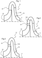
- Fig.1, Fig.2 and Fig.3 each shows a different embodiment of a stage 10 of a centrifugal compressor, each comprising a different embodiment of a stator blade 100 according to the subject-matter disclosed herein installed downstream of an impeller 20 of the compressor.
- the centrifugal compressor may be employed in a variety of different oil and gas applications, including: production, transportation, refinery, petrochemical and chemical industries, handling a very large variety of gases and mixtures of gases in a wide range of operating conditions (pressure and temperature).
- Fig. 1 shows an embodiment in which the stator blade 100 is installed in a return channel 30 of the compressor to act as a return channel blade of the compressor itself.
- Fig. 2 shows an embodiment in which the stator blade 100 is installed in a diffuser 25 to act as a diffuser blade of the compressor itself.
- Fig. 3 shows an embodiment in which the stator blade 100 extends at least partially through both the diffuser 25 and the return channel 30 of the compressor and through a 180° turn between the diffuser 25 and the return channel 30.
- the position of the stator blade 100 in the compressor stage 10 is arranged and positioned in order for the stator blade 100 to be invested by the above-mentioned gas flow and to deviate it to lower or cancel its circumferential velocity component.
- the stator blade 100 is arranged and positioned in order to maintain the gas flow attached to its external surface, limiting or avoiding flow separations, from the leading edge 102 to the trailing edge 104 at least when the compressor is operated at its design operational speed.
- the stator blade 100 has a curved external surface configured to guide the gas flow from the leading edge 102 to the trailing edge 104 of the stator blade 100 itself.
- the external surface of the stator blade 100 comprises a pressure surface 112, that extends between the leading edge 102 and the trailing 104 on the "lower side” of the stator blade 100, and a suction surface 114 that extends between the leading edge 102 and the trailing 104 on the "upper side” of the stator blade 100.
- the pressure surface 112 identifies the portion of the external surface of the stator blade 100 which is subject to a pressure higher than the pressure of the surrounding the gas flow under normal operational conditions.
- the suction surface 114 identifies the portion of the external surface which is subject to a pressure lower than the pressure of the surrounding the gas flow under normal operational conditions.
- the suction surface 114 is convex and the pressure surface 112 is concave or has a lower convexity than the suction surface 114.
- the stator blade 100 comprises a front portion 110 arranged to receive a gas flow coming from e.g. the impeller 20 and to split it in a pressure-side gas flow adjacent to the pressure surface 112 and in a suction-side gas flow adjacent to the suction surface 114.
- the front portion 110 is configured to generate at least one streamwise vortex "V" in the gas flow adjacent to the external surface of the stator blade 100. According to the invention the front portion 110 is configured to generate at least a couple of counter-rotating streamwise vortices "V", as shown in Fig.5 and Fig.7 . In a possible embodiment shown in Fig.6 , the front portion 110 is configured to generate a plurality of couples of counter-rotating streamwise vortices "V".
- the streamwise vortices "V" have a diameter comprised between a minimum value and a maximum value.
- the front portion 110 is configured to generate streamwise vortices "V" which have a diameter proportional to the median spanwise dimension of the stator blade 100 (and thus of the width of the channel in which the stator blade 100 is installed) and inversely proportional to the total number of streamwise vortices "V".
- the leading edge 102 of the stator blade 100 has at least four oblique stretch 103, configured to generate a streamwise vortex "V" of the above-mentioned type.
- the oblique stretches 103 define an angle of attack with the incoming gas flow and cause the streamwise vortices "V” by lowering the pressure of the incoming gas flow.
- the oblique layout of the oblique stretches 103 determine an uneven distribution of pressure in the spanwise direction of the stator blade 100; this causes the establishment of a spanwise velocity component in the flow which leads to the formation of one of the streamwise vortices "V" shown in Fig.7 .
- the leading edge 102 has a plurality of oblique stretches 103.
- Fig.4 , Fig.11 and Fig.15 show stator blades 100 in which the leading edge 102 has two oblique stretches 103.
- Fig. 12 and Fig.16 show stator blades 100 in which the leading edge 102 has four oblique stretches 103.
- Fig.13 and Fig.17 show stator blades 100 in which the leading edge 102 has eight oblique stretches 103.
- Fig.14 and Fig.18 show stator blades 100 in which the leading edge 102 has six oblique stretches 103.
- the leading edge 102 has only one oblique stretch 103.
- the oblique stretches 103 are oblique with respect to a spanwise direction of the stator blade 100 and can be either straight (as shown in Fig.4 , Fig.11, Fig.12, Fig.13 and Fig.14 ), or curved (as shown in Fig.15, Fig.16, Fig.17 and Fig.18 ).
- the oblique stretches 103 configured as described above are also oblique with respect to the direction of the gas flow investing the front portion 110.
- the front portion 110 comprises at least one pointed protrusion 120 having a vertex 125.
- Fig.4 , Fig.11 and Fig.15 show stator blades 100 in which the front portion 110 comprises a single pointed protrusion 120.
- Fig.12 and Fig.16 show stator blades 100 in which the front portion 110 comprises two pointed protrusions 120.
- Fig.13 and Fig.17 show stator blades 100 in which the front portion 110 comprises four pointed protrusions 120.
- Each pointed protrusion 120 defines at least two of the oblique stretches 103 of the leading edge 102 described above.
- the two oblique stretches 103 are positioned at opposite sides of the vertex 125 and are configured to generate two counter-rotating streamwise vortices "V".
- the pointed protrusions 120 have a triangular shape in a median plane of the stator blade 100 and defines the straight oblique stretches 103.
- the pointed protrusions 120 have a cusp shape in a median plane of the stator blade 100 and define the curved oblique stretches 103.
- the pointed protrusions 120 project in a forward direction which defines an angle between 20° and -20° with respect to a line tangent at a front end of a stretch of the mean camber line of the stator blade 100 located at the front portion 110; this stretch starts from the leading edge of the blade (excluding the pointed protrusion) and may amount for example to 10-20% of the total length of the mean camber line.
- the forward direction in which the pointed protrusion 120 project is substantially tangent to the above-mentioned stretch of the mean camber line located at the front portion 110.
- the stator blade 100 comprises a plurality of pointed protrusions 120 projecting in different forward directions; a forward direction defines an angle between 20° and -20° with respect to a line tangent at a front end of a stretch of said mean camber line; this stretch is located at the front portion 110 of the stator blade 100 and starts from the leading edge of the stator blade 100 (excluding the pointed protrusion).
- each pointed protrusion 120 is symmetrical with respect to a longitudinal plane of the stator blade 100.
- the stator blade 100 comprises one or more asymmetrical pointed protrusions 120 in which the oblique stretches 103 relative to the pointed protrusion 120 define different angles with respect to the spanwise direction of the stator blade 100.
- the pointed protrusions 120 have a longitudinal extension along the forward direction comprised between a minimum value and a maximum value.
- the minimum value is given by the formula 0.2 b / M and the maximum value of the extension is given by the formula 2. 0 b / M , wherein b is the median spanwise dimension of the stator blade 100 and M is the number of pointed protrusions 120 in the front portion 110.
- the leading edge 102 has a vertex angle of less than 60° at the vertex 125 of the pointed protrusions 120, more preferably less than 50°.
- the vertex angle is to be intended as the angle between the two oblique stretches 103 adjacent to the same vertex 125. More in detail, the vertex angle should be measured in a camber plain of the stator blade 100.
- the stator blade 100 has a spanwise variable airfoil, wherein the airfoil changes gradually between a vertex airfoil located at the pointed protrusion 120 and a trough airfoil located next to (at some distance from) the pointed protrusion 120 or in a trough 126 between two pointed protrusions 120. More in detail, the vertex airfoil has a sharp leading edge 102a and the trough airfoil has either a sharp or a rounded leading edge.
- Fig. 19 shows a sharp leading edge airfoil which can be employed as the vertex airfoil.
- the pointed protrusion 120 projects in a forward direction D; in general, the forward direction defines an angle between 20° and -20° with respect to a line tangent at a front end of a stretch 128 of the mean camber line; stretch 128 is located at front portion 110 of stator blade 100 and starts (see point 129) from the leading edge of stator blade 100 (excluding the pointed protrusion); in the embodiment of Fig. 19 , forward direction D coincides with the tangent line, i.e. the angle is 0°.
- Fig.20 shows a round leading edge airfoil which can be employed as the trough airfoil.
- Fig.8 shows an embodiment of the stator blade 100 having a sharp leading edge 102a extending along the whole spanwise dimension.
- Fig.9 shows an embodiment of the stator blade 100 having a sharp leading edge 120a at the vertex 125 extending spanwise for a portion of the spanwise dimension and then changing to a rounded leading 120 on the sides of the stator blade 100.
- Fig. 10 shows an embodiment of the stator blade 100 having a sharp leading edge 102a only at the vertex 125 of the pointed protrusion 120, immediately changing to a round leading edge 102b at the sides of the vertex 125.
- the subject-matter disclosed herein provides a centrifugal compressor 2100, preferably of multi-stage type, which comprises a plurality of stator blades 100 of the type described above.
- the centrifugal compressor comprises a plurality of compressor stages 10, each having an impeller 20, a diffuser 25 and a return channel 30, and each compressor stage 10 comprises a plurality of stator blades 100 arranged in a circular array in the diffuser 25 and/or in the return channel 30.
- the circular arrays of stator blades 100 extends around the longitudinal axis "Z" in order to receive an incoming flow from the impeller 20 of the compressor stage 10 having a circumferential component of the velocity around the longitudinal axis "Z" and to change the direction of the flow in order to lower or cancel the circumferential component of the velocity and to deliver a clean, straight flow to the rotor of the following compressor stage.
- the centrifugal compressor 2100 has an inlet 2101 for receiving a (e.g. non-compressed) working fluid and an outlet 2199 for ejecting the working fluid after compression.
- Compressor 2100 comprises for example three compression stages fluidly coupled; a first (or initial) compression stage includes an impeller 2112 and downstream thereof an annular conduit 2114 leading to the next stage; a second (or intermediate) compression stage includes an impeller 2122 and downstream thereof an annular conduit 2124 leading to the next stage; a third (or final) compression stage includes an impeller 2132 and downstream thereof an annular conduit 2134 leading to the next stage.
- one or more stator blades configured to generate at least one streamwise vortex in the working fluid flow are located in one or more or all of the annular conduits 2114 and 2124 and 2134.
Landscapes
- Engineering & Computer Science (AREA)
- Mechanical Engineering (AREA)
- General Engineering & Computer Science (AREA)
- Physics & Mathematics (AREA)
- Fluid Mechanics (AREA)
- Chemical & Material Sciences (AREA)
- Chemical Kinetics & Catalysis (AREA)
- General Chemical & Material Sciences (AREA)
- Combustion & Propulsion (AREA)
- Structures Of Non-Positive Displacement Pumps (AREA)
Description
- The subject-matter disclosed herein relates to the field of centrifugal compressors for the oil & gas industry. In particular, the subject-matter disclosed herein relates to a stator blade for a centrifugal compressor which can be used for defining return channels for example in multi-stage centrifugal compressors.
- In centrifugal compressors, the rotor accelerates a gas flow in a circumferential direction around an axis in order to compress it centrifugally. Stator blades are usually placed downstream of one or more impellers of the rotor to straighten the gas flow following compression, in particular to correct the radial circumferential component of the velocity.
EP-A-0 648 939 discloses a centrifugal compressor.EP-A-1873402 discloses a compressor for a turbocharger.KR-A-20180019416 US-A-2967013 discloses a diffuser.JP-A-2012072735 GB-A- 2237071 - For example, in multi-stage compressors having one or more impellers, stator blades are placed in return channels between two consecutive impellers in order to receive a gas flow from the first rotor and direct it to the second rotor and straighten it in the process.
- The shape of the stator blade interacts with the fluid differently depending on the flow conditions which depend on the operative condition of the compressor.
- Typically, the stator blades design is optimized to cause a smooth flow around the blade at the design operational speed of the compressor. However, these blades may create losses when the compressor does not operate at its operational design speed, for example during start-up or shut-down or in operational conditions that require a continuous change of the compressor speed.
- In these conditions, prior-art stator blades optimized for just one operative condition tend to cause local or even total flow separations, which cause stalls or recirculation areas and impact the performance of the compressor.
- Therefore, it would be desirable to provide a stator blade which could operate over a wider range of operative conditions avoiding flow separations or at least reducing flow separations.
- According to one aspect, the subject-matter disclosed herein relates to a stator blade for a centrifugal compressor as defined in claim 1.
- According to another aspect, the subject-matter disclosed herein relates to a centrifugal compressor comprising at least one stator blade as defined in claim 13.
- A more complete appreciation of the disclosed embodiments of the invention and many of the attendant advantages thereof will be readily obtained as the same becomes better understood by reference to the following detailed description when considered in connection with the accompanying drawings, wherein:
-
Fig. 1, Fig. 2 and Fig. 3 illustrate meridional schematic views of respective embodiments of a centrifugal compressor disclosed herein comprising respective embodiments of a stator blade disclosed herein; -
Fig. 4 illustrates a prospective view of a stator blade not forming part of the invention; -
Fig. 5 and Fig. 6 illustrate front schematic views of an operational configuration of respective embodiments of a stator blade disclosed herein; -
Fig. 7 illustrates a partial top view of an operational configuration of a stator blade not forming part of the invention; -
Fig. 8, Fig. 9 and Fig. 10 illustrate front schematic views of respective embodiment of a stator blade disclosed herein; -
Fig. 11, Fig. 12, Fig. 13, Fig. 14 ,Fig. 15, Fig. 16, Fig. 17 and Fig. 18 illustrate top schematic views of a stator blade, the stator blade according toFig. 11 to Fig. 15 not forming part of the invention and the stator blade according toFig. 16 to Fig. 18 showing different embodiments disclosed herein; -
Fig.19 and Fig.20 illustrate section views of respective embodiments of a stator blade disclosed herein; and -
Fig.21 illustrates schematically an embodiment of a compressor. - The subject matter herein disclosed relates to a stator blade to be positioned in a compressor, downstream of an impeller of the rotor, in order to straighten the gas flow coming from the impeller. The stator blade has a front portion configured to generate one or more streamwise vortices in the gas flow which follow the stream of the flow and remain attached to an upper surface (also known as the "suction surface") of the stator blades.
- A streamwise vortex is a vortex which extends parallel to the direction of the flow and defines a "vortex tube" in which the flow moves with a substantially helical trajectory. The streamwise vortices shuffle the boundary layer of the flow on the upper surface of the stator blade, re-energizing the boundary layer in order to prevent or delay the detachment of the flow from the surface, therefore delaying and/or reducing the entity of a stall of the stator blade. "Streamwise vorticity" and its generation are known as such from textbooks, for example from the book "Internal Flow - Concepts and Applications" of E. M. Greitzer, C. S. Tan and M. B. Graf published in 2004 and e-published in 2007 by Cambridge University Press.
- More in detail, the vortices are generate by at least two pointed protrusions located in the front portion of the stator blade and are carried downstream by the gas flow along the upper surface of the blade.
- Reference now will be made in detail to embodiments of the disclosure, one or more examples of which are illustrated in the drawings. Each example is provided by way of explanation of the disclosure, not limitation of the disclosure. In fact, it will be apparent to those skilled in the art that various modifications and variations can be made in the present disclosure without departing from the scope of the disclosure. Reference throughout the specification to "one embodiment" or "an embodiment" or "some embodiments" means that the particular feature, structure or characteristic described in connection with an embodiment is included in at least one embodiment of the subject matter disclosed. Thus, the appearance of the phrase "in one embodiment" or "in an embodiment" or "in some embodiments" in various places throughout the specification is not necessarily referring to the same embodiment(s).
- When introducing elements of various embodiments the articles "a", "an", "the", and "said" are intended to mean that there are one or more of the elements. The terms "comprising", "including", and "having" are intended to be inclusive and mean that there may be additional elements other than the listed elements.
-
Fig. 4 discloses astator blade 100 for a centrifugal compressor, in particular for a multi-stage centrifugal compressor to be used in a plant for processing gasses such as methane, ethane, propane, ethylene, carbon dioxide, helium, argon, hydrogen, refrigerant gasses or a mixture of these substances. -
Fig.1, Fig.2 and Fig.3 each shows a different embodiment of astage 10 of a centrifugal compressor, each comprising a different embodiment of astator blade 100 according to the subject-matter disclosed herein installed downstream of animpeller 20 of the compressor. The centrifugal compressor may be employed in a variety of different oil and gas applications, including: production, transportation, refinery, petrochemical and chemical industries, handling a very large variety of gases and mixtures of gases in a wide range of operating conditions (pressure and temperature). - More in detail,
Fig. 1 shows an embodiment in which thestator blade 100 is installed in areturn channel 30 of the compressor to act as a return channel blade of the compressor itself.Fig. 2 shows an embodiment in which thestator blade 100 is installed in adiffuser 25 to act as a diffuser blade of the compressor itself.Fig. 3 shows an embodiment in which thestator blade 100 extends at least partially through both thediffuser 25 and thereturn channel 30 of the compressor and through a 180° turn between thediffuser 25 and thereturn channel 30. - It is to be noted that, according to a variant of the embodiment of
Fig. 2 , there are blades according to the subject-matter disclosed herein both in the diffuser and in the return channel. - The gas flow coming from e.g. the
impeller 20 has a velocity comprising a radial component and a circumferential component with respect to the longitudinal axis "Z" of thecompressor stage 10. Thestator blade 100 is either fixed tocompressor stage 10 or configured to be arranged in thecompressor stage 10, in thediffuser 25 and/or thereturn channel 30 in a predetermined position. - The position of the
stator blade 100 in thecompressor stage 10 is arranged and positioned in order for thestator blade 100 to be invested by the above-mentioned gas flow and to deviate it to lower or cancel its circumferential velocity component. Thestator blade 100 is arranged and positioned in order to maintain the gas flow attached to its external surface, limiting or avoiding flow separations, from the leadingedge 102 to thetrailing edge 104 at least when the compressor is operated at its design operational speed. - More in detail, the
stator blade 100 has a curved external surface configured to guide the gas flow from the leadingedge 102 to thetrailing edge 104 of thestator blade 100 itself. The external surface of thestator blade 100 comprises apressure surface 112, that extends between the leadingedge 102 and the trailing 104 on the "lower side" of thestator blade 100, and asuction surface 114 that extends between the leadingedge 102 and the trailing 104 on the "upper side" of thestator blade 100. Thepressure surface 112 identifies the portion of the external surface of thestator blade 100 which is subject to a pressure higher than the pressure of the surrounding the gas flow under normal operational conditions. Thesuction surface 114 identifies the portion of the external surface which is subject to a pressure lower than the pressure of the surrounding the gas flow under normal operational conditions. In general, thesuction surface 114 is convex and thepressure surface 112 is concave or has a lower convexity than thesuction surface 114. - The
stator blade 100 comprises afront portion 110 arranged to receive a gas flow coming from e.g. theimpeller 20 and to split it in a pressure-side gas flow adjacent to thepressure surface 112 and in a suction-side gas flow adjacent to thesuction surface 114. - The
front portion 110 is configured to generate at least one streamwise vortex "V" in the gas flow adjacent to the external surface of thestator blade 100. According to the invention thefront portion 110 is configured to generate at least a couple of counter-rotating streamwise vortices "V", as shown inFig.5 andFig.7 . In a possible embodiment shown inFig.6 , thefront portion 110 is configured to generate a plurality of couples of counter-rotating streamwise vortices "V". - Preferably, the streamwise vortices "V" have a diameter comprised between a minimum value and a maximum value.
- In particular, the
front portion 110 is configured to generate streamwise vortices "V" which have a diameter proportional to the median spanwise dimension of the stator blade 100 (and thus of the width of the channel in which thestator blade 100 is installed) and inversely proportional to the total number of streamwise vortices "V". - Preferably, the
leading edge 102 of thestator blade 100 has at least fouroblique stretch 103, configured to generate a streamwise vortex "V" of the above-mentioned type. In particular, the oblique stretches 103 define an angle of attack with the incoming gas flow and cause the streamwise vortices "V" by lowering the pressure of the incoming gas flow. The oblique layout of the oblique stretches 103 determine an uneven distribution of pressure in the spanwise direction of thestator blade 100; this causes the establishment of a spanwise velocity component in the flow which leads to the formation of one of the streamwise vortices "V" shown inFig.7 . - Preferably, the
leading edge 102 has a plurality of oblique stretches 103.Fig.4 ,Fig.11 andFig.15 show stator blades 100 in which theleading edge 102 has two oblique stretches 103.Fig. 12 andFig.16 show stator blades 100 in which theleading edge 102 has four oblique stretches 103.Fig.13 andFig.17 show stator blades 100 in which theleading edge 102 has eight oblique stretches 103.Fig.14 andFig.18 show stator blades 100 in which theleading edge 102 has six oblique stretches 103. In anon-illustrated stator blade 100 not forming part of the invention, theleading edge 102 has only oneoblique stretch 103. - In particular, the oblique stretches 103 are oblique with respect to a spanwise direction of the
stator blade 100 and can be either straight (as shown inFig.4 ,Fig.11, Fig.12, Fig.13 and Fig.14 ), or curved (as shown inFig.15, Fig.16, Fig.17 and Fig.18 ). Advantageously, the oblique stretches 103 configured as described above are also oblique with respect to the direction of the gas flow investing thefront portion 110. - The
front portion 110 comprises at least one pointedprotrusion 120 having avertex 125.Fig.4 ,Fig.11 andFig.15 show stator blades 100 in which thefront portion 110 comprises a singlepointed protrusion 120.Fig.12 andFig.16 show stator blades 100 in which thefront portion 110 comprises two pointedprotrusions 120.Fig.13 andFig.17 show stator blades 100 in which thefront portion 110 comprises four pointedprotrusions 120. - Each pointed
protrusion 120 defines at least two of the oblique stretches 103 of theleading edge 102 described above. In particular, the twooblique stretches 103 are positioned at opposite sides of thevertex 125 and are configured to generate two counter-rotating streamwise vortices "V". - In
Fig.4 ,Fig. 11, Fig.12, Fig.13 and Fig.14 , the pointedprotrusions 120 have a triangular shape in a median plane of thestator blade 100 and defines the straight oblique stretches 103. InFig. 15, Fig. 16, Fig.17 and Fig.18 , the pointedprotrusions 120 have a cusp shape in a median plane of thestator blade 100 and define the curved oblique stretches 103. - Preferably, the pointed
protrusions 120 project in a forward direction which defines an angle between 20° and -20° with respect to a line tangent at a front end of a stretch of the mean camber line of thestator blade 100 located at thefront portion 110; this stretch starts from the leading edge of the blade (excluding the pointed protrusion) and may amount for example to 10-20% of the total length of the mean camber line. InFig.4 , the forward direction in which the pointedprotrusion 120 project is substantially tangent to the above-mentioned stretch of the mean camber line located at thefront portion 110. - In a possible non-illustrated embodiment, the
stator blade 100 comprises a plurality of pointedprotrusions 120 projecting in different forward directions; a forward direction defines an angle between 20° and -20° with respect to a line tangent at a front end of a stretch of said mean camber line; this stretch is located at thefront portion 110 of thestator blade 100 and starts from the leading edge of the stator blade 100 (excluding the pointed protrusion). - Preferably, each pointed
protrusion 120 is symmetrical with respect to a longitudinal plane of thestator blade 100. According to a possible alternative non-illustrated embodiment of thestator blade 100 comprises one or more asymmetricalpointed protrusions 120 in which the oblique stretches 103 relative to thepointed protrusion 120 define different angles with respect to the spanwise direction of thestator blade 100. - Preferably, the pointed
protrusions 120 have a longitudinal extension along the forward direction comprised between a minimum value and a maximum value. The minimum value is given by the formula 0.2b/M and the maximum value of the extension is given by the formula 2. 0b/M, wherein b is the median spanwise dimension of thestator blade 100 and M is the number of pointedprotrusions 120 in thefront portion 110. - Preferably, the
leading edge 102 has a vertex angle of less than 60° at thevertex 125 of the pointedprotrusions 120, more preferably less than 50°. The vertex angle is to be intended as the angle between the twooblique stretches 103 adjacent to thesame vertex 125. More in detail, the vertex angle should be measured in a camber plain of thestator blade 100. - Preferably, the
stator blade 100 has a spanwise variable airfoil, wherein the airfoil changes gradually between a vertex airfoil located at thepointed protrusion 120 and a trough airfoil located next to (at some distance from) the pointedprotrusion 120 or in atrough 126 between two pointedprotrusions 120. More in detail, the vertex airfoil has a sharp leading edge 102a and the trough airfoil has either a sharp or a rounded leading edge. -
Fig. 19 shows a sharp leading edge airfoil which can be employed as the vertex airfoil. In this figure, thepointed protrusion 120 projects in a forward direction D; in general, the forward direction defines an angle between 20° and -20° with respect to a line tangent at a front end of astretch 128 of the mean camber line;stretch 128 is located atfront portion 110 ofstator blade 100 and starts (see point 129) from the leading edge of stator blade 100 (excluding the pointed protrusion); in the embodiment ofFig. 19 , forward direction D coincides with the tangent line, i.e. the angle is 0°. -
Fig.20 shows a round leading edge airfoil which can be employed as the trough airfoil. -
Fig.8 shows an embodiment of thestator blade 100 having a sharp leading edge 102a extending along the whole spanwise dimension.Fig.9 shows an embodiment of thestator blade 100 having a sharp leading edge 120a at thevertex 125 extending spanwise for a portion of the spanwise dimension and then changing to a rounded leading 120 on the sides of thestator blade 100.Fig. 10 shows an embodiment of thestator blade 100 having a sharp leading edge 102a only at thevertex 125 of thepointed protrusion 120, immediately changing to a round leading edge 102b at the sides of thevertex 125. - According to another aspect and with reference to
Fig.1, Fig.2, Fig.3 andFig. 21 , the subject-matter disclosed herein provides acentrifugal compressor 2100, preferably of multi-stage type, which comprises a plurality ofstator blades 100 of the type described above. In particular, the centrifugal compressor comprises a plurality of compressor stages 10, each having animpeller 20, adiffuser 25 and areturn channel 30, and eachcompressor stage 10 comprises a plurality ofstator blades 100 arranged in a circular array in thediffuser 25 and/or in thereturn channel 30. More in detail, the circular arrays ofstator blades 100 extends around the longitudinal axis "Z" in order to receive an incoming flow from theimpeller 20 of thecompressor stage 10 having a circumferential component of the velocity around the longitudinal axis "Z" and to change the direction of the flow in order to lower or cancel the circumferential component of the velocity and to deliver a clean, straight flow to the rotor of the following compressor stage. - According to the embodiment of
Fig.21 , thecentrifugal compressor 2100 has aninlet 2101 for receiving a (e.g. non-compressed) working fluid and anoutlet 2199 for ejecting the working fluid after compression.Compressor 2100 comprises for example three compression stages fluidly coupled; a first (or initial) compression stage includes animpeller 2112 and downstream thereof anannular conduit 2114 leading to the next stage; a second (or intermediate) compression stage includes animpeller 2122 and downstream thereof anannular conduit 2124 leading to the next stage; a third (or final) compression stage includes animpeller 2132 and downstream thereof anannular conduit 2134 leading to the next stage. As already explained, one or more stator blades configured to generate at least one streamwise vortex in the working fluid flow are located in one or more or all of theannular conduits
Claims (16)
- A stator blade (100) for a centrifugal compressor, said stator blade (100) comprising a front portion (110) arranged to receive a gas flow and having an external surface configured to guide said gas flow adjacent to said external surface, characterized in that said front portion (110) has a leading edge (102) configured to generate at least one streamwise vortex (V) in said gas flow, the axis of the vortex (V) being substantially parallel to the direction of the gas flow,the leading edge (102) having at least two pointed protrusions (120) each having a vertex (125) with a cusp shape defining two oblique stretches (103) that are curved; andadjacent oblique stretches (103) of the pair of protrusions (120) together forming a rounded trough (126) therebetween.
- The stator blade (100) of claim 1, wherein said front portion (110) is configured to generate at least one couple of counter-rotating streamwise vortices (V) in said gas flow on the oblique stretches (103).
- The stator blade (100) of claim 1 or 2, wherein said streamwise vortex (V) has a diameter comprised between a minimum value and a maximum value.
- The stator blade (100) of any preceding claims, wherein said external surface comprises a pressure surface (112) and a suction surface (114), and wherein said front portion (110) is arranged to split said gas flow in a pressure-side gas flow adjacent to the pressure surface (112) and in a suction-side gas flow adjacent to the suction surface (114).
- The stator blade (100) of claim 1 having a mean camber line, wherein the at least two pointed protrusions (120) project in a forward direction (D), said forward direction (D) defining an angle between 20° and -20° with respect to a line tangent at a front end of a stretch (128) of said mean camber line, said stretch (128) being located at the front portion (110) of the stator blade (100) and starting from the leading edge of the stator blade (100).
- The stator blade (100) of claim 5 wherein said forward direction (D) is substantially tangent to said stretch (128) of the mean camber line.
- The stator blade (100) of claim 5 or 6, having a plurality of pointed protrusions (120) projecting in respective different forward directions, a forward direction defining an angle between 20° and -20° with respect to a line tangent at a front end of a stretch (128) of said mean camber line, said stretch (128) being located at the front portion (110) of the stator blade (100) and starting from the leading edge of the stator blade (100).
- The stator blade (100) of claim 5 or 6 or 7, wherein a pointed protrusion (120) have an extension along the forward direction comprised between a minimum value and a maximum value, the minimum value of the extension being given by the formula 0.2b/M and the maximum value of the extension being given by the formula 2.0b/M wherein b is a median spanwise dimension of the stator blade (100) and M is the number of pointed protrusions (120) in the front portion (110).
- The stator blade (100) of any preceding claim, wherein a pointed protrusion (120) is symmetrical or asymmetrical.
- The stator blade (100) of any preceding claim, wherein the leading edge (102) has a vertex angle of less than 60° at the vertex (125) of the protrusion (120), preferably vertex angle being less than 50°.
- The stator blade (100) of any preceding claim, being arranged to be used as a return channel blade of a multi-stage centrifugal compressor.
- The stator blade (100) of any preceding claim, being arranged to be used as a diffuser blade of a centrifugal compressor.
- A centrifugal compressor (2100) for gas processing plants comprising at least a stator blade (100) according to any preceding claim from 1 to 12.
- The centrifugal compressor (2100) of claim 13 wherein said compressor is multi-stage and has a plurality of compressor stages (10), at least one compressor stage (10) having a rotor (20), a diffuser (25) and a return channel (30), said compressor comprising a plurality of stator blades (100) according to any preceding claim from 1 to 12 arranged in at least one circular array in the return channel (30) of said at least one compressor stage (10).
- The centrifugal compressor (2100) of claim 13 wherein said compressor is multi-stage and has a plurality of compressor stages (10), at least one compressor stage (10) having a rotor (20), a diffuser (25) and a return channel (30), said compressor comprising a plurality of stator blades (100) according to any preceding claim from 1 to 12 arranged in at least one circular array in the diffuser (25) of said at least one compressor stage (10).
- The centrifugal compressor (2100) of claim 13 wherein said compressor is multi-stage and has a plurality of compressor stages (10), at least one compressor stage (10) having a rotor (20), a diffuser (25) and a return channel (30), said compressor comprising a plurality of stator blades (100) according to any preceding claim from 1 to 12 arranged in at least one circular array in the diffuser (25) and in the return channel (30) of said at least one compressor stage (10).
Applications Claiming Priority (2)
| Application Number | Priority Date | Filing Date | Title |
|---|---|---|---|
| IT102019000006674A IT201900006674A1 (en) | 2019-05-09 | 2019-05-09 | Stator vane for a centrifugal compressor |
| PCT/EP2020/025211 WO2020224807A1 (en) | 2019-05-09 | 2020-05-07 | Stator blade for a centrifugal compressor |
Publications (2)
| Publication Number | Publication Date |
|---|---|
| EP3966457A1 EP3966457A1 (en) | 2022-03-16 |
| EP3966457B1 true EP3966457B1 (en) | 2025-06-25 |
Family
ID=67470579
Family Applications (1)
| Application Number | Title | Priority Date | Filing Date |
|---|---|---|---|
| EP20725617.3A Active EP3966457B1 (en) | 2019-05-09 | 2020-05-07 | Stator blade for a centrifugal compressor |
Country Status (10)
| Country | Link |
|---|---|
| US (1) | US11965527B2 (en) |
| EP (1) | EP3966457B1 (en) |
| JP (1) | JP7485697B2 (en) |
| KR (1) | KR102725420B1 (en) |
| CN (1) | CN113906222B (en) |
| AU (1) | AU2020268493B2 (en) |
| CA (1) | CA3138818C (en) |
| ES (1) | ES3039868T3 (en) |
| IT (1) | IT201900006674A1 (en) |
| WO (1) | WO2020224807A1 (en) |
Families Citing this family (1)
| Publication number | Priority date | Publication date | Assignee | Title |
|---|---|---|---|---|
| JP7755460B2 (en) * | 2021-11-04 | 2025-10-16 | 三菱重工業株式会社 | Vaned Diffusers and Centrifugal Compressors |
Family Cites Families (19)
| Publication number | Priority date | Publication date | Assignee | Title |
|---|---|---|---|---|
| US2967013A (en) * | 1954-10-18 | 1961-01-03 | Garrett Corp | Diffuser |
| US4349314A (en) * | 1980-05-19 | 1982-09-14 | The Garrett Corporation | Compressor diffuser and method |
| GB2237071A (en) * | 1989-10-18 | 1991-04-24 | Rolls Royce Plc | Compressor assembly |
| JP3912331B2 (en) | 1993-10-18 | 2007-05-09 | 株式会社日立プラントテクノロジー | Centrifugal fluid machine |
| JP3482668B2 (en) * | 1993-10-18 | 2003-12-22 | 株式会社日立製作所 | Centrifugal fluid machine |
| US5598990A (en) * | 1994-12-15 | 1997-02-04 | University Of Kansas Center For Research Inc. | Supersonic vortex generator |
| US6318677B1 (en) | 1999-08-06 | 2001-11-20 | Charles J. Dixon | Method and apparatus for generating a stable leading-edge lifting-vortex controller |
| EP1873402A1 (en) * | 2006-06-26 | 2008-01-02 | Siemens Aktiengesellschaft | Compressor in particular for turbocharger |
| JP2012072735A (en) * | 2010-09-29 | 2012-04-12 | Kobe Steel Ltd | Centrifugal compressor |
| JP5766595B2 (en) * | 2011-12-15 | 2015-08-19 | 三菱重工業株式会社 | Centrifugal turbomachine |
| US9581034B2 (en) * | 2013-03-14 | 2017-02-28 | Elliott Company | Turbomachinery stationary vane arrangement for disk and blade excitation reduction and phase cancellation |
| DE102015216579A1 (en) | 2015-08-31 | 2017-03-02 | Ziehl-Abegg Se | Fan, fan and system with at least one fan |
| GB201602895D0 (en) * | 2016-02-19 | 2016-04-06 | Rolls Royce Plc | Aerofoil |
| US10465520B2 (en) * | 2016-07-22 | 2019-11-05 | General Electric Company | Blade with corrugated outer surface(s) |
| KR102592234B1 (en) * | 2016-08-16 | 2023-10-20 | 한화파워시스템 주식회사 | Centrifugal compressor |
| WO2018161069A1 (en) * | 2017-03-03 | 2018-09-07 | Elliott Company | Method and arrangement to minimize noise and excitation of structures due to cavity acoustic modes |
| FR3065023B1 (en) * | 2017-04-07 | 2019-04-12 | Safran Aircraft Engines | REINFORCED AXIAL DIFFUSER |
| WO2019027661A1 (en) * | 2017-07-31 | 2019-02-07 | Siemens Aktiengesellschaft | Gas turbine exhaust diffuser having flow guiding elements |
| JP7005393B2 (en) * | 2018-03-09 | 2022-01-21 | 三菱重工業株式会社 | Diffuser vane and centrifugal compressor |
-
2019
- 2019-05-09 IT IT102019000006674A patent/IT201900006674A1/en unknown
-
2020
- 2020-05-07 CN CN202080038087.5A patent/CN113906222B/en active Active
- 2020-05-07 KR KR1020217039681A patent/KR102725420B1/en active Active
- 2020-05-07 ES ES20725617T patent/ES3039868T3/en active Active
- 2020-05-07 US US17/594,982 patent/US11965527B2/en active Active
- 2020-05-07 JP JP2021565998A patent/JP7485697B2/en active Active
- 2020-05-07 WO PCT/EP2020/025211 patent/WO2020224807A1/en not_active Ceased
- 2020-05-07 CA CA3138818A patent/CA3138818C/en active Active
- 2020-05-07 EP EP20725617.3A patent/EP3966457B1/en active Active
- 2020-05-07 AU AU2020268493A patent/AU2020268493B2/en active Active
Also Published As
| Publication number | Publication date |
|---|---|
| KR102725420B1 (en) | 2024-11-01 |
| ES3039868T3 (en) | 2025-10-27 |
| KR20210151252A (en) | 2021-12-13 |
| US11965527B2 (en) | 2024-04-23 |
| US20220299044A1 (en) | 2022-09-22 |
| CN113906222A (en) | 2022-01-07 |
| IT201900006674A1 (en) | 2020-11-09 |
| AU2020268493B2 (en) | 2023-12-21 |
| WO2020224807A1 (en) | 2020-11-12 |
| JP7485697B2 (en) | 2024-05-16 |
| CA3138818C (en) | 2024-01-09 |
| CN113906222B (en) | 2024-10-29 |
| CA3138818A1 (en) | 2020-11-12 |
| JP2022531884A (en) | 2022-07-12 |
| AU2020268493A1 (en) | 2021-12-02 |
| EP3966457A1 (en) | 2022-03-16 |
Similar Documents
| Publication | Publication Date | Title |
|---|---|---|
| CN101563526B (en) | Diffuser and exhaust system for turbine | |
| US6203275B1 (en) | Centrifugal compressor and diffuser for centrifugal compressor | |
| JP5068263B2 (en) | Lean type centrifugal compressor airfoil diffuser | |
| EP1082545B1 (en) | Turbomachinery impeller | |
| EP2075408A2 (en) | Last stage stator blade of a steam turbine low-pressure section | |
| US10352237B2 (en) | Diffuser having shaped vanes | |
| US11885350B2 (en) | Outflow region of a compressor, compressor having an outflow region of said type, and turbocharger having the compressor | |
| US11035380B2 (en) | Diffuser vane and centrifugal compressor | |
| US11435079B2 (en) | Diffuser pipe with axially-directed exit | |
| EP3966457B1 (en) | Stator blade for a centrifugal compressor | |
| US20170298737A1 (en) | Turbomachine | |
| EP2176521B1 (en) | Steam turbine stage | |
| US11702962B2 (en) | Steam turbine configured to recover static pressure of steam in diffuser | |
| KR20030063369A (en) | Axial flow turbo compressor | |
| US20250305421A1 (en) | Stator part having a fin, in a turbine engine | |
| RU2785571C1 (en) | Stator vane for a centrifugal compressor | |
| US11136993B2 (en) | Diffuser pipe with asymmetry | |
| KR20170121692A (en) | Mixed flow impeller having forward curved blade with mean camber line shape section of airfoil | |
| RU2021122590A (en) | MULTI-STAGE FLUID CENTRIFUGAL MACHINE |
Legal Events
| Date | Code | Title | Description |
|---|---|---|---|
| STAA | Information on the status of an ep patent application or granted ep patent |
Free format text: STATUS: UNKNOWN |
|
| STAA | Information on the status of an ep patent application or granted ep patent |
Free format text: STATUS: THE INTERNATIONAL PUBLICATION HAS BEEN MADE |
|
| PUAI | Public reference made under article 153(3) epc to a published international application that has entered the european phase |
Free format text: ORIGINAL CODE: 0009012 |
|
| STAA | Information on the status of an ep patent application or granted ep patent |
Free format text: STATUS: REQUEST FOR EXAMINATION WAS MADE |
|
| 17P | Request for examination filed |
Effective date: 20211126 |
|
| AK | Designated contracting states |
Kind code of ref document: A1 Designated state(s): AL AT BE BG CH CY CZ DE DK EE ES FI FR GB GR HR HU IE IS IT LI LT LU LV MC MK MT NL NO PL PT RO RS SE SI SK SM TR |
|
| RAP3 | Party data changed (applicant data changed or rights of an application transferred) |
Owner name: NUOVO PIGNONE TECNOLOGIE S.R.L. |
|
| DAV | Request for validation of the european patent (deleted) | ||
| DAX | Request for extension of the european patent (deleted) | ||
| P01 | Opt-out of the competence of the unified patent court (upc) registered |
Effective date: 20230526 |
|
| STAA | Information on the status of an ep patent application or granted ep patent |
Free format text: STATUS: EXAMINATION IS IN PROGRESS |
|
| 17Q | First examination report despatched |
Effective date: 20230828 |
|
| GRAP | Despatch of communication of intention to grant a patent |
Free format text: ORIGINAL CODE: EPIDOSNIGR1 |
|
| STAA | Information on the status of an ep patent application or granted ep patent |
Free format text: STATUS: GRANT OF PATENT IS INTENDED |
|
| RIC1 | Information provided on ipc code assigned before grant |
Ipc: F01D 5/14 20060101ALI20250226BHEP Ipc: F01D 9/04 20060101ALI20250226BHEP Ipc: F04D 29/44 20060101AFI20250226BHEP |
|
| GRAS | Grant fee paid |
Free format text: ORIGINAL CODE: EPIDOSNIGR3 |
|
| INTG | Intention to grant announced |
Effective date: 20250307 |
|
| RAP3 | Party data changed (applicant data changed or rights of an application transferred) |
Owner name: NUOVO PIGNONE TECNOLOGIE - S.R.L. |
|
| GRAA | (expected) grant |
Free format text: ORIGINAL CODE: 0009210 |
|
| STAA | Information on the status of an ep patent application or granted ep patent |
Free format text: STATUS: THE PATENT HAS BEEN GRANTED |
|
| AK | Designated contracting states |
Kind code of ref document: B1 Designated state(s): AL AT BE BG CH CY CZ DE DK EE ES FI FR GB GR HR HU IE IS IT LI LT LU LV MC MK MT NL NO PL PT RO RS SE SI SK SM TR |
|
| REG | Reference to a national code |
Ref country code: GB Ref legal event code: FG4D |
|
| REG | Reference to a national code |
Ref country code: CH Ref legal event code: EP |
|
| REG | Reference to a national code |
Ref country code: DE Ref legal event code: R096 Ref document number: 602020053300 Country of ref document: DE |
|
| REG | Reference to a national code |
Ref country code: CH Ref legal event code: EP |
|
| REG | Reference to a national code |
Ref country code: IE Ref legal event code: FG4D |
|
| PG25 | Lapsed in a contracting state [announced via postgrant information from national office to epo] |
Ref country code: FI Free format text: LAPSE BECAUSE OF FAILURE TO SUBMIT A TRANSLATION OF THE DESCRIPTION OR TO PAY THE FEE WITHIN THE PRESCRIBED TIME-LIMIT Effective date: 20250625 |
|
| REG | Reference to a national code |
Ref country code: LT Ref legal event code: MG9D |
|
| PG25 | Lapsed in a contracting state [announced via postgrant information from national office to epo] |
Ref country code: GR Free format text: LAPSE BECAUSE OF FAILURE TO SUBMIT A TRANSLATION OF THE DESCRIPTION OR TO PAY THE FEE WITHIN THE PRESCRIBED TIME-LIMIT Effective date: 20250926 |
|
| PG25 | Lapsed in a contracting state [announced via postgrant information from national office to epo] |
Ref country code: BG Free format text: LAPSE BECAUSE OF FAILURE TO SUBMIT A TRANSLATION OF THE DESCRIPTION OR TO PAY THE FEE WITHIN THE PRESCRIBED TIME-LIMIT Effective date: 20250625 |
|
| PG25 | Lapsed in a contracting state [announced via postgrant information from national office to epo] |
Ref country code: HR Free format text: LAPSE BECAUSE OF FAILURE TO SUBMIT A TRANSLATION OF THE DESCRIPTION OR TO PAY THE FEE WITHIN THE PRESCRIBED TIME-LIMIT Effective date: 20250625 |
|
| PG25 | Lapsed in a contracting state [announced via postgrant information from national office to epo] |
Ref country code: RS Free format text: LAPSE BECAUSE OF FAILURE TO SUBMIT A TRANSLATION OF THE DESCRIPTION OR TO PAY THE FEE WITHIN THE PRESCRIBED TIME-LIMIT Effective date: 20250925 |
|
| REG | Reference to a national code |
Ref country code: ES Ref legal event code: FG2A Ref document number: 3039868 Country of ref document: ES Kind code of ref document: T3 Effective date: 20251027 |
|
| PG25 | Lapsed in a contracting state [announced via postgrant information from national office to epo] |
Ref country code: LV Free format text: LAPSE BECAUSE OF FAILURE TO SUBMIT A TRANSLATION OF THE DESCRIPTION OR TO PAY THE FEE WITHIN THE PRESCRIBED TIME-LIMIT Effective date: 20250625 |
|
| REG | Reference to a national code |
Ref country code: NL Ref legal event code: MP Effective date: 20250625 |
|
| PG25 | Lapsed in a contracting state [announced via postgrant information from national office to epo] |
Ref country code: NL Free format text: LAPSE BECAUSE OF FAILURE TO SUBMIT A TRANSLATION OF THE DESCRIPTION OR TO PAY THE FEE WITHIN THE PRESCRIBED TIME-LIMIT Effective date: 20250625 |
|
| PG25 | Lapsed in a contracting state [announced via postgrant information from national office to epo] |
Ref country code: PT Free format text: LAPSE BECAUSE OF FAILURE TO SUBMIT A TRANSLATION OF THE DESCRIPTION OR TO PAY THE FEE WITHIN THE PRESCRIBED TIME-LIMIT Effective date: 20251027 |
|
| REG | Reference to a national code |
Ref country code: AT Ref legal event code: MK05 Ref document number: 1806686 Country of ref document: AT Kind code of ref document: T Effective date: 20250625 |
|
| PG25 | Lapsed in a contracting state [announced via postgrant information from national office to epo] |
Ref country code: IS Free format text: LAPSE BECAUSE OF FAILURE TO SUBMIT A TRANSLATION OF THE DESCRIPTION OR TO PAY THE FEE WITHIN THE PRESCRIBED TIME-LIMIT Effective date: 20251025 |
|
| PG25 | Lapsed in a contracting state [announced via postgrant information from national office to epo] |
Ref country code: AT Free format text: LAPSE BECAUSE OF FAILURE TO SUBMIT A TRANSLATION OF THE DESCRIPTION OR TO PAY THE FEE WITHIN THE PRESCRIBED TIME-LIMIT Effective date: 20250625 Ref country code: SM Free format text: LAPSE BECAUSE OF FAILURE TO SUBMIT A TRANSLATION OF THE DESCRIPTION OR TO PAY THE FEE WITHIN THE PRESCRIBED TIME-LIMIT Effective date: 20250625 |
|
| PG25 | Lapsed in a contracting state [announced via postgrant information from national office to epo] |
Ref country code: PL Free format text: LAPSE BECAUSE OF FAILURE TO SUBMIT A TRANSLATION OF THE DESCRIPTION OR TO PAY THE FEE WITHIN THE PRESCRIBED TIME-LIMIT Effective date: 20250625 |
|
| PG25 | Lapsed in a contracting state [announced via postgrant information from national office to epo] |
Ref country code: EE Free format text: LAPSE BECAUSE OF FAILURE TO SUBMIT A TRANSLATION OF THE DESCRIPTION OR TO PAY THE FEE WITHIN THE PRESCRIBED TIME-LIMIT Effective date: 20250625 |
|
| PG25 | Lapsed in a contracting state [announced via postgrant information from national office to epo] |
Ref country code: SK Free format text: LAPSE BECAUSE OF FAILURE TO SUBMIT A TRANSLATION OF THE DESCRIPTION OR TO PAY THE FEE WITHIN THE PRESCRIBED TIME-LIMIT Effective date: 20250625 |
|
| PG25 | Lapsed in a contracting state [announced via postgrant information from national office to epo] |
Ref country code: DK Free format text: LAPSE BECAUSE OF FAILURE TO SUBMIT A TRANSLATION OF THE DESCRIPTION OR TO PAY THE FEE WITHIN THE PRESCRIBED TIME-LIMIT Effective date: 20250625 |
|
| PG25 | Lapsed in a contracting state [announced via postgrant information from national office to epo] |
Ref country code: IT Free format text: LAPSE BECAUSE OF FAILURE TO SUBMIT A TRANSLATION OF THE DESCRIPTION OR TO PAY THE FEE WITHIN THE PRESCRIBED TIME-LIMIT Effective date: 20250625 |
|
| PLBE | No opposition filed within time limit |
Free format text: ORIGINAL CODE: 0009261 |
|
| STAA | Information on the status of an ep patent application or granted ep patent |
Free format text: STATUS: NO OPPOSITION FILED WITHIN TIME LIMIT |