EP3966415B1 - Sliding door systems - Google Patents
Sliding door systems Download PDFInfo
- Publication number
- EP3966415B1 EP3966415B1 EP20801787.1A EP20801787A EP3966415B1 EP 3966415 B1 EP3966415 B1 EP 3966415B1 EP 20801787 A EP20801787 A EP 20801787A EP 3966415 B1 EP3966415 B1 EP 3966415B1
- Authority
- EP
- European Patent Office
- Prior art keywords
- assembly
- door
- module
- pinion
- latch mechanism
- Prior art date
- Legal status (The legal status is an assumption and is not a legal conclusion. Google has not performed a legal analysis and makes no representation as to the accuracy of the status listed.)
- Active
Links
Images






Classifications
-
- E—FIXED CONSTRUCTIONS
- E05—LOCKS; KEYS; WINDOW OR DOOR FITTINGS; SAFES
- E05F—DEVICES FOR MOVING WINGS INTO OPEN OR CLOSED POSITION; CHECKS FOR WINGS; WING FITTINGS NOT OTHERWISE PROVIDED FOR, CONCERNED WITH THE FUNCTIONING OF THE WING
- E05F1/00—Closers or openers for wings, not otherwise provided for in this subclass
- E05F1/08—Closers or openers for wings, not otherwise provided for in this subclass spring-actuated, e.g. for horizontally sliding wings
- E05F1/16—Closers or openers for wings, not otherwise provided for in this subclass spring-actuated, e.g. for horizontally sliding wings for sliding wings
-
- E—FIXED CONSTRUCTIONS
- E05—LOCKS; KEYS; WINDOW OR DOOR FITTINGS; SAFES
- E05F—DEVICES FOR MOVING WINGS INTO OPEN OR CLOSED POSITION; CHECKS FOR WINGS; WING FITTINGS NOT OTHERWISE PROVIDED FOR, CONCERNED WITH THE FUNCTIONING OF THE WING
- E05F5/00—Braking devices, e.g. checks; Stops; Buffers
- E05F5/003—Braking devices, e.g. checks; Stops; Buffers for sliding wings
-
- E—FIXED CONSTRUCTIONS
- E05—LOCKS; KEYS; WINDOW OR DOOR FITTINGS; SAFES
- E05D—HINGES OR SUSPENSION DEVICES FOR DOORS, WINDOWS OR WINGS
- E05D15/00—Suspension arrangements for wings
- E05D15/06—Suspension arrangements for wings for wings sliding horizontally more or less in their own plane
- E05D15/0621—Details, e.g. suspension or supporting guides
- E05D15/0626—Details, e.g. suspension or supporting guides for wings suspended at the top
- E05D15/063—Details, e.g. suspension or supporting guides for wings suspended at the top on wheels with fixed axis
-
- E—FIXED CONSTRUCTIONS
- E05—LOCKS; KEYS; WINDOW OR DOOR FITTINGS; SAFES
- E05Y—INDEXING SCHEME ASSOCIATED WITH SUBCLASSES E05D AND E05F, RELATING TO CONSTRUCTION ELEMENTS, ELECTRIC CONTROL, POWER SUPPLY, POWER SIGNAL OR TRANSMISSION, USER INTERFACES, MOUNTING OR COUPLING, DETAILS, ACCESSORIES, AUXILIARY OPERATIONS NOT OTHERWISE PROVIDED FOR, APPLICATION THEREOF
- E05Y2201/00—Constructional elements; Accessories therefor
- E05Y2201/20—Brakes; Disengaging means; Holders; Stops; Valves; Accessories therefor
- E05Y2201/262—Type of motion, e.g. braking
- E05Y2201/264—Type of motion, e.g. braking linear
-
- E—FIXED CONSTRUCTIONS
- E05—LOCKS; KEYS; WINDOW OR DOOR FITTINGS; SAFES
- E05Y—INDEXING SCHEME ASSOCIATED WITH SUBCLASSES E05D AND E05F, RELATING TO CONSTRUCTION ELEMENTS, ELECTRIC CONTROL, POWER SUPPLY, POWER SIGNAL OR TRANSMISSION, USER INTERFACES, MOUNTING OR COUPLING, DETAILS, ACCESSORIES, AUXILIARY OPERATIONS NOT OTHERWISE PROVIDED FOR, APPLICATION THEREOF
- E05Y2201/00—Constructional elements; Accessories therefor
- E05Y2201/20—Brakes; Disengaging means; Holders; Stops; Valves; Accessories therefor
- E05Y2201/262—Type of motion, e.g. braking
- E05Y2201/266—Type of motion, e.g. braking rotary
-
- E—FIXED CONSTRUCTIONS
- E05—LOCKS; KEYS; WINDOW OR DOOR FITTINGS; SAFES
- E05Y—INDEXING SCHEME ASSOCIATED WITH SUBCLASSES E05D AND E05F, RELATING TO CONSTRUCTION ELEMENTS, ELECTRIC CONTROL, POWER SUPPLY, POWER SIGNAL OR TRANSMISSION, USER INTERFACES, MOUNTING OR COUPLING, DETAILS, ACCESSORIES, AUXILIARY OPERATIONS NOT OTHERWISE PROVIDED FOR, APPLICATION THEREOF
- E05Y2201/00—Constructional elements; Accessories therefor
- E05Y2201/40—Motors; Magnets; Springs; Weights; Accessories therefor
- E05Y2201/404—Function thereof
- E05Y2201/41—Function thereof for closing
- E05Y2201/414—Function thereof for closing for the initial closing movement
-
- E—FIXED CONSTRUCTIONS
- E05—LOCKS; KEYS; WINDOW OR DOOR FITTINGS; SAFES
- E05Y—INDEXING SCHEME ASSOCIATED WITH SUBCLASSES E05D AND E05F, RELATING TO CONSTRUCTION ELEMENTS, ELECTRIC CONTROL, POWER SUPPLY, POWER SIGNAL OR TRANSMISSION, USER INTERFACES, MOUNTING OR COUPLING, DETAILS, ACCESSORIES, AUXILIARY OPERATIONS NOT OTHERWISE PROVIDED FOR, APPLICATION THEREOF
- E05Y2201/00—Constructional elements; Accessories therefor
- E05Y2201/60—Suspension or transmission members; Accessories therefor
- E05Y2201/606—Accessories therefor
- E05Y2201/61—Cooperation between suspension or transmission members
- E05Y2201/612—Cooperation between suspension or transmission members between carriers and rails
- E05Y2201/614—Anti-derailing means
-
- E—FIXED CONSTRUCTIONS
- E05—LOCKS; KEYS; WINDOW OR DOOR FITTINGS; SAFES
- E05Y—INDEXING SCHEME ASSOCIATED WITH SUBCLASSES E05D AND E05F, RELATING TO CONSTRUCTION ELEMENTS, ELECTRIC CONTROL, POWER SUPPLY, POWER SIGNAL OR TRANSMISSION, USER INTERFACES, MOUNTING OR COUPLING, DETAILS, ACCESSORIES, AUXILIARY OPERATIONS NOT OTHERWISE PROVIDED FOR, APPLICATION THEREOF
- E05Y2201/00—Constructional elements; Accessories therefor
- E05Y2201/60—Suspension or transmission members; Accessories therefor
- E05Y2201/622—Suspension or transmission members elements
- E05Y2201/64—Carriers
-
- E—FIXED CONSTRUCTIONS
- E05—LOCKS; KEYS; WINDOW OR DOOR FITTINGS; SAFES
- E05Y—INDEXING SCHEME ASSOCIATED WITH SUBCLASSES E05D AND E05F, RELATING TO CONSTRUCTION ELEMENTS, ELECTRIC CONTROL, POWER SUPPLY, POWER SIGNAL OR TRANSMISSION, USER INTERFACES, MOUNTING OR COUPLING, DETAILS, ACCESSORIES, AUXILIARY OPERATIONS NOT OTHERWISE PROVIDED FOR, APPLICATION THEREOF
- E05Y2201/00—Constructional elements; Accessories therefor
- E05Y2201/60—Suspension or transmission members; Accessories therefor
- E05Y2201/622—Suspension or transmission members elements
- E05Y2201/644—Flexible elongated pulling elements
- E05Y2201/654—Cables
-
- E—FIXED CONSTRUCTIONS
- E05—LOCKS; KEYS; WINDOW OR DOOR FITTINGS; SAFES
- E05Y—INDEXING SCHEME ASSOCIATED WITH SUBCLASSES E05D AND E05F, RELATING TO CONSTRUCTION ELEMENTS, ELECTRIC CONTROL, POWER SUPPLY, POWER SIGNAL OR TRANSMISSION, USER INTERFACES, MOUNTING OR COUPLING, DETAILS, ACCESSORIES, AUXILIARY OPERATIONS NOT OTHERWISE PROVIDED FOR, APPLICATION THEREOF
- E05Y2201/00—Constructional elements; Accessories therefor
- E05Y2201/60—Suspension or transmission members; Accessories therefor
- E05Y2201/622—Suspension or transmission members elements
- E05Y2201/71—Toothed gearing
- E05Y2201/716—Pinions
-
- E—FIXED CONSTRUCTIONS
- E05—LOCKS; KEYS; WINDOW OR DOOR FITTINGS; SAFES
- E05Y—INDEXING SCHEME ASSOCIATED WITH SUBCLASSES E05D AND E05F, RELATING TO CONSTRUCTION ELEMENTS, ELECTRIC CONTROL, POWER SUPPLY, POWER SIGNAL OR TRANSMISSION, USER INTERFACES, MOUNTING OR COUPLING, DETAILS, ACCESSORIES, AUXILIARY OPERATIONS NOT OTHERWISE PROVIDED FOR, APPLICATION THEREOF
- E05Y2201/00—Constructional elements; Accessories therefor
- E05Y2201/60—Suspension or transmission members; Accessories therefor
- E05Y2201/622—Suspension or transmission members elements
- E05Y2201/71—Toothed gearing
- E05Y2201/722—Racks
-
- E—FIXED CONSTRUCTIONS
- E05—LOCKS; KEYS; WINDOW OR DOOR FITTINGS; SAFES
- E05Y—INDEXING SCHEME ASSOCIATED WITH SUBCLASSES E05D AND E05F, RELATING TO CONSTRUCTION ELEMENTS, ELECTRIC CONTROL, POWER SUPPLY, POWER SIGNAL OR TRANSMISSION, USER INTERFACES, MOUNTING OR COUPLING, DETAILS, ACCESSORIES, AUXILIARY OPERATIONS NOT OTHERWISE PROVIDED FOR, APPLICATION THEREOF
- E05Y2600/00—Mounting or coupling arrangements for elements provided for in this subclass
- E05Y2600/40—Mounting location; Visibility of the elements
- E05Y2600/46—Mounting location; Visibility of the elements in or on the wing
-
- E—FIXED CONSTRUCTIONS
- E05—LOCKS; KEYS; WINDOW OR DOOR FITTINGS; SAFES
- E05Y—INDEXING SCHEME ASSOCIATED WITH SUBCLASSES E05D AND E05F, RELATING TO CONSTRUCTION ELEMENTS, ELECTRIC CONTROL, POWER SUPPLY, POWER SIGNAL OR TRANSMISSION, USER INTERFACES, MOUNTING OR COUPLING, DETAILS, ACCESSORIES, AUXILIARY OPERATIONS NOT OTHERWISE PROVIDED FOR, APPLICATION THEREOF
- E05Y2800/00—Details, accessories and auxiliary operations not otherwise provided for
- E05Y2800/20—Combinations of elements
- E05Y2800/23—Combinations of elements of elements of different categories
- E05Y2800/24—Combinations of elements of elements of different categories of springs and brakes
-
- E—FIXED CONSTRUCTIONS
- E05—LOCKS; KEYS; WINDOW OR DOOR FITTINGS; SAFES
- E05Y—INDEXING SCHEME ASSOCIATED WITH SUBCLASSES E05D AND E05F, RELATING TO CONSTRUCTION ELEMENTS, ELECTRIC CONTROL, POWER SUPPLY, POWER SIGNAL OR TRANSMISSION, USER INTERFACES, MOUNTING OR COUPLING, DETAILS, ACCESSORIES, AUXILIARY OPERATIONS NOT OTHERWISE PROVIDED FOR, APPLICATION THEREOF
- E05Y2900/00—Application of doors, windows, wings or fittings thereof
- E05Y2900/10—Application of doors, windows, wings or fittings thereof for buildings or parts thereof
- E05Y2900/13—Type of wing
- E05Y2900/132—Doors
Definitions
- the present disclosure generally relates to sliding door systems, and more particularly but not exclusively relates to top-hung sliding door systems.
- the present invention relates to a movement assistance mechanism as defined in claim 1.
- Various embodiments of this movement assistance mechanism form the subject-matter of dependent claims 2 to 6.
- Also claimed is a module as defined in claims 7 to 9, an assembly as defined in claims 10 and 11, as well as a system as defined in claims 12 and 13.
- closure assembly 100 With reference to FIG. 1 , illustrated therein is a closure assembly 100.
- the closure assembly 100 is mounted to a wall 90 having an opening 92 formed therein, and a doorframe 94 is mounted to the wall 90 and defines the opening 92.
- the closure assembly 100 includes a rail assembly 110 and a door assembly 150 movably mounted to the rail assembly 110.
- the door assembly 150 is movable along the rail assembly 110 in opposite opening and closing directions between a closed position in which the door assembly 150 substantially covers the opening 92 and an open position in which the opening 92 is substantially uncovered by the door assembly 150.
- the rail assembly 110 has a first end portion 111 and a second end portion 112, and generally includes an elongated rail member 120 and at least one of a closing-side engagement zone 130 or an opening-side engagement zone 140.
- the closing-side engagement zone 130 is configured to interface with the door assembly 150 as the door assembly 150 approaches the closed position
- the opening-side engagement zone 140 is configured to interface with the door assembly 150 as the door assembly 150 approaches the open position. Further details regarding the interaction of the door assembly 150 with the closing-side engagement zone 130 and the opening-side engagement zone 140 are provided herein.
- the rail member 120 includes a vertical plate 122 by which the rail member 120 is secured to the wall 90 by a plurality of fasteners 102 such as screws, a first or upper horizontal support 124 extending laterally from the vertical plate 122, and a second or lower horizontal support 126 positioned below and to the side of the first horizontal support 124.
- a flange 123 Formed near the top of the vertical plate 122 is a flange 123, which may, in certain embodiments, support a rack member 114.
- the first support 124 includes a first mounting feature 125
- the second support 126 includes a second mounting feature 127 and a longitudinally-extending rail 128.
- the rail 128 is a single continuous rail that extends the length of the rail member 120. In other embodiments, the rail 128 may be provided as two or more separate rail sections separated by one or more gaps.
- the closing-side engagement zone 130 includes a closing-side trigger 132 and a closing-side rack 134, each of which is fixed to the rail member 120 in the first end portion 111 of the rail assembly 110, for example above the opening 92.
- the trigger 132 may be mounted to the first support 124 via the first mounting feature 125
- the rack gear 134 may be mounted to the second support 126 via the second mounting feature 127.
- the rack gear 134 is configured to interface with a rotary damper 176 of the door assembly 150, and may alternatively be referred to as the closing-side damper rack 134.
- the opening-side engagement zone 140 includes an opening-side trigger 142 and an opening-side rack gear 144, each of which is fixed to the rail member 120 in second end portion 112 of the rail assembly 110.
- the trigger 142 may be mounted to the first support 124 via the first mounting feature 125
- the rack gear 144 may be mounted to the second support 126 via the second mounting feature 127.
- the rack gear 144 is configured to interface with a rotary damper 186 of the door assembly 150, and may alternatively be referred to as the opening-side damper rack 144.
- the illustrated door assembly 150 generally includes a door panel 160, a closing-side module 170, and an opening-side module 180, and may further include a central module 190.
- the door panel 160 includes a closing-side vertical edge 162, an opening-side vertical edge 164, a broad vertical face 166, and a horizontal top edge 168 extending connected to the edges 162, 164 and the broad face 166.
- each of the closing-side module 170 and the opening-side module 180 is mounted to the top edge 168.
- one or both of the modules 170, 180 may be mounted to the broad face 166.
- the closing-side module 170 generally includes a frame 172, an anti-jump lug 173 projecting from the frame 172, a wheel 174 rotatably mounted to the frame 172, a rotary damper 176 mounted to the frame 172, and a movement assistance mechanism 178 mounted to the frame 172.
- the wheel 174 includes a groove 175 in which the rail 128 is seated such that the rail member 120 supports the closing-side module 170 and the door panel 160 to which the module 170 is mounted.
- the anti-jump lug 173 is positioned below the rail 128, and hinders the module 170 from lifting off of the rail 128.
- the rotary damper 176 includes a pinion gear 177 operable to engage the closing-side rack 134 such that movement of the door panel 160 to and from its fully closed position causes the rack 134 to rotate the pinion 177 in opposite directions.
- the rotary damper 176 is configured to resist rotation of the pinion 177 in the direction corresponding to the closing direction of the door assembly 150 such that movement of the door panel 160 to its fully closed position is resisted by the rotary damper 176.
- the rotary damper 176 is provided as a one-way rotary damper 176 that resists rotation of the pinion 177 in the rotational direction corresponding to closing movement of the door assembly 150, but does not resist rotation of the pinion 177 in the rotational direction corresponding to opening movement of the door assembly 150. In such forms, movement of the door panel 160 from its fully closed position in the opening direction is not resisted by the rotary damper 176.
- the movement assistance mechanism 178 includes a latch 179 operable to engage the closing-side trigger 132 as the door panel 160 approaches its fully closed position.
- the latch 179 has a cocked position in which the latch 179 retains a spring of the movement assistance mechanism 178 in a deformed state in which mechanical energy is stored in the spring.
- the closing-side trigger 132 engages the latch 179 and drives the latch 179 from the cocked position to a release position, thereby causing the spring to release its mechanical energy and draw the door panel 160 toward its fully closed position.
- Further details regarding exemplary forms of the movement assistance mechanism 178 are provided below with reference to the movement assistance mechanism 200, not presently claimed, and the force-multiplying movement assistance mechanism 300 of the invention.
- the opening-side module 180 is essentially a mirror image of the closing-side module 180.
- the opening-side module 180 generally includes a frame 182, an anti-jump lug 183 projecting from the frame 182, a wheel 184 rotatably mounted to the frame 182, a rotary damper 186 mounted to the frame 182, and a movement assistance mechanism 188 mounted to the frame 182.
- the wheel 184 includes a groove 185 in which the rail 128 is seated such that the rail member 120 supports the opening-side module 180 and the door panel 160 to which the module 180 is mounted.
- the anti-jump lug 183 is positioned below the rail 128, and hinders the module 180 from lifting off of the rail 128.
- the rotary damper 186 includes a pinion gear 187 operable to engage the opening-side rack 144 such that movement of the door assembly 150 to and from its fully open position causes the rack 144 to rotate the pinion 187 in opposite directions.
- the rotary damper 186 is configured to resist rotation of the pinion 187 in the direction corresponding to the opening direction of the door assembly 150 such that movement of the door panel 160 to its fully open position is resisted by the rotary damper 186.
- the rotary damper 186 is provided as a one-way rotary damper 186 that resists rotation of the pinion 187 in the rotational direction corresponding to open movement of the door assembly 150, but does not resist rotation of the pinion 187 in the rotational direction corresponding to closing movement of the door assembly 150. In such forms, movement of the door panel 160 from its fully open position in the closing direction is not resisted by the rotary damper 180.
- the movement assistance mechanism 188 includes a latch 189 operable to engage the opening-side trigger 142 as the door assembly 150 approaches its fully open position.
- the latch 189 has a cocked position in which the latch 189 retains a spring of the movement assistance mechanism 188 in a deformed state, in which mechanical energy is stored in the spring.
- the opening-side trigger 142 engages the latch 189 and drives the latch 189 from the cocked position to a release position, thereby causing the spring to release its mechanical energy and draw the door panel 160 toward its fully open position. Further details regarding exemplary forms of the movement assistance mechanism 188 are provided below with reference to the movement assistance mechanism 200, not presently claimed, and the force-multiplying movement assistance mechanism 300 of the invention.
- the center module 190 generally includes a frame 192, an anti-jump lug 193 projecting from the frame 192, and a wheel 194 rotatably mounted to the frame 192.
- the wheel 194 includes a groove 195 in which the rail 128 is seated such that the rail member 120 supports the center module 190 and the door 160 to which the module 190 is mounted.
- the anti-jump lug 193 is positioned below the rail 128, and hinders the module 190 from lifting off of the rail 128.
- the movement assistance mechanism 200 may, for example, be utilized as the closing-side movement assistance mechanism 178 and/or the opening-side movement assistance mechanism 188.
- the movement assistance mechanism 200 generally includes a housing 210, a latch mechanism 220 movably mounted to the housing 210, and a biasing mechanism 230 connected between the housing 210 and the latch mechanism 220.
- the housing 210 includes a first portion 211 and a second portion 212 that are coupled to one another to define an internal chamber 213 in which the biasing mechanism 230 is mounted, and a channel 214 through which the latch mechanism 220 projects.
- the first portion 211 also defines a track 216 having a straight portion 217 and an angled jog 218, and the second portion 212 defines a mirror image track facing the track 216.
- the latch mechanism 220 includes a body portion 222, first and second arms 224, 226 projecting from a first side of the body portion 222 and defining a recess 225 therebetween, and a finger 228 projecting from an opposite second side of the body portion 222.
- the latch mechanism 220 is slidably mounted to the housing 210 by a first pivot pin 202 and a second pivot pin 204, each of which projects into the tracks 216 such that the housing 210 movably supports the latch mechanism 220 and guides the latch mechanism 220 along the path defined by the tracks 216.
- the biasing mechanism 230 includes a base 232 and a spring 234 having a first end 235 and an opposite second end 236.
- the first end 235 is coupled to the base 232, which is pivotably mounted to the housing 210.
- the second end 236 is coupled to the finger 228 such that the spring 234 biases the latch mechanism 220 toward a home position.
- the latch mechanism 220 is biased toward a home position by the biasing mechanism 230, and is movable to a cocked position in which the biasing mechanism 230 is loaded such that mechanical energy is stored in the spring 234.
- each of the pivot pins 202, 204 is received in the straight portion 217 of the track 216. Movement of the latch mechanism 220 toward the cocked position stretches the spring 234, thereby loading the biasing mechanism 230 and storing mechanical energy in the spring 234.
- the first pivot pin 202 is received in the angled jog 218.
- the jog 218 retains the latch mechanism 220 in the cocked position against the biasing force of the spring 234, which urges the latch mechanism 220 toward its home position.
- the movement assistance mechanism 200 may be utilized as the closing assistance mechanism 178 of the closing-side module 170.
- the movement assistance mechanism 200 cooperates with the closing-side engagement zone 130 to assist movement of the door assembly 150 toward its fully closed position.
- the latch mechanism 220 is in its home position, and the closing-side trigger 132 is received in the recess 225.
- the closing-side trigger 132 engages the second arm 226 and drives the latch mechanism 220 to its cocked position, thereby stretching the spring 234.
- the rotary damper 176 travels along the closing-side rack 134, thereby rotating the pinion 177 in the direction corresponding to opening movement of the door assembly 150.
- this rotation of the pinion 177 is not resisted by the damper 176, such that the damper 176 does not add to the force required to move the door assembly 150 from the fully closed position.
- the latch mechanism 220 travels to its cocked position, at which point the trigger 132 exits the recess 225.
- the latch mechanism 220 is retained in the cocked position by engagement between the jog 218 and the pin 202.
- the closing-side trigger 132 engages the first arm 224 to pivot the latch mechanism 220 to a release position, thereby causing the pin 202 to exit the jog 218.
- the spring 234 drives the latch mechanism 220 toward its home position, thereby pulling the door panel 160 toward its fully closed position.
- the movement assistance mechanism 200 aids in the final closing movement of the door panel 160 when utilized as the closing assistance mechanism 178 of the closing-side module 170. It should be appreciated that this final closing movement is slowed by the rotary damper 176, the pinion 177 of which engages the closing-side rack 134 during the closing movement of the door assembly 150. Due to the fact that the rotary damper 176 resists rotation of the pinion in the direction corresponding to closing movement of the door assembly 150, engagement between the damper 176 and the rack 134 slows the final closing movement of the door assembly 150.
- the movement assistance mechanism 200 may additionally or alternatively be utilized as the opening assistance mechanism 188 of the opening-side module 180.
- the movement assistance mechanism 200 will cooperate with the opening-side engagement zone 140 to assist movement of the door assembly 150 toward the fully open position in a manner analogous to that described above with reference to the use of the movement assistance mechanism 200 as the closing assistance mechanism 178 of the closing-side module 170.
- the final opening movement of the door assembly 150 will be slowed by engagement between the opening-side damper 186 and the opening-side rack 144 in a manner analogous to that described above with reference to the closing-side damper 176 and the closing-side rack 134.
- the movement assistance mechanism 300 may, for example, be utilized as the closing-side movement assistance mechanism 178 and/or the opening-side movement assistance mechanism 188.
- the movement assistance mechanism 300 includes a housing 310, a latch mechanism 320 movably mounted to the housing 310, a biasing mechanism 330 connected between the housing 310 and the latch mechanism 320, and a gear train 340 connected with the latch mechanism 320.
- the housing 310 includes a first portion 311 and a second portion 312 that are coupled to one another to define an internal chamber 313 in which the biasing mechanism 330 is mounted, and a channel 314 through which a portion of the latch mechanism 320 projects. As illustrated in FIG. 9 , the housing 310 defines a first track 350 and a second track 360 proximate the first track 350, further details of which are provided below. Each of the first track 350 and the second track 360 includes a first run formed in the first portion 311, and includes a mirror image second run formed in the second portion 312.
- the latch mechanism 320 includes a carriage 321 movably mounted to the housing 310 and a latch body 323 movably mounted to the carriage 321.
- the carriage 321 includes a lateral slot 322, and is movably coupled to the housing 310 by a first pin 302 and a second pin 304.
- Each of the pins 302, 304 projects into the first track 350 such that the housing 310 constrains movement of the carriage 321 to the path defined by the first track 350.
- the latch body 323 includes a body portion 327 and a head 328 formed on one end of the body portion 327.
- One end of the body portion 327 is movably coupled with the carriage 321 and the housing 310 by a third pin 306, which extends through the lateral slot 322.
- the pin 306 also extends into the second track 360 such that the housing 310 constrains movement of the latch body to the path defined by the second track 360.
- the pins 302, 304, 306 are separate components that are coupled to the latch mechanism 320.
- one or more of the pins 302, 304, 306 may be formed integrally with a corresponding portion of the latch mechanism 320.
- the body portion 327 of the latch body 323 extends through a gap formed between the first and second pins 302, 304 to the head 328, which includes first and second arms 324, 326 having a recess 325 defined therebetween.
- the biasing mechanism 330 includes a spring 334 having a first end 335 and an opposite second end 336.
- the first end 335 is coupled to the housing 310, and the second end 336 is coupled to the carriage 321 such that the spring 334 biases the latch mechanism 320 toward a home position (to the left in FIG. 8 ).
- the gear train 340 is movably mounted to the housing 310, and generally includes a pinion gear 342, an input gear 343 rotationally coupled with the pinion gear 342, one or more intermediate gears 344 operably engaged with the input gear 343, and a rack member 346 including a rack gear 347 engaged with the input gear 343 via the one or more intermediate gears 344.
- the pinion gear 342 is mounted to the exterior of the housing 310 such that the pinion gear 342 is operable to engage the rack gear 114 as the door assembly 150 moves between its open position and its closed position.
- the one or more intermediate gears 344 operably couple the rack member 346 with the input gear 343 such that rotation of the pinion gear 342 causes a corresponding longitudinal movement of the rack member 346.
- the rack member 346 includes an arm 348 defining an aperture 349, and a pin 306 extends through the carriage 321 and into the aperture 349, thereby operably coupling the rack member 346 with the latch mechanism 320.
- rotation of the pinion gear 342 in one rotational direction causes the rack member 346 to pull the latch mechanism 320 to the cocked position, thereby stretching and storing mechanical energy in the spring 334.
- the first track 350 includes a proximal end portion 352, an opposite distal end portion 354, and an intermediate portion 356 extending between and connecting the proximal end portion 352 and the distal end portion 354.
- Each of the proximal end portion 352 and the intermediate portion 356 extends substantially parallel to a longitudinal axis 301 of the movement assistance mechanism 300, and the distal end portion 354 defines an angled jog 355 that extends laterally inward (i.e., away from the channel 314).
- the second track 360 includes a proximal end portion 362, an opposite distal end portion 364, and an intermediate portion 366 extending between and connecting the proximal end portion 362 and the distal end portion 364.
- the intermediate portion 366 extends substantially parallel to the longitudinal axis 301, the proximal end portion 362 defines a second angled jog 363 extending away from the channel 314, and the distal end portion 364 defines a recess 365 extending away from the channel 314.
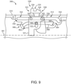
- FIG. 9 illustrates the latch mechanism 320 in an intermediate position between the cocked position and the home position.
- each of the first pin 302 and the second pin 304 is received in the intermediate portion 356 of the first track 350, such that the carriage 321 is substantially straight relative to the housing 310.
- the third pin 306 is received in the intermediate portion 366 of the second track 360 such that the latch body 323 has an extended position relative to the carriage 321.
- the latch mechanism 320 is operable to move proximally toward the home position ( FIG. 10 ) or distally toward the cocked position ( FIG. 11 ).
- proximal movement of the latch mechanism 320 from the intermediate position ( FIG. 9 ) to the home position ( FIG. 10 ) causes the third pin 306 to travel into the jog 363 defined by the proximal end portion 362 of the second track 360.
- the jog 363 urges the pin 306 laterally inward, thereby moving the latch body 323 to a retracted position relative to the carriage 321.
- distal movement of the latch mechanism 320 from the intermediate position ( FIG. 9 ) to the cocked position ( FIG. 11 ) causes the first pin 302 to enter the angled jog 355 defined by the distal end portion 354 of the first track 350, thereby angling the latch mechanism 320 relative to the housing 310.
- the jog 355 and/or the recess 365 retains the latch mechanism 320 in the cocked position against the biasing force exerted by the spring 334.
- the movement assistance mechanism 300 is configured to interface with the rack member 114 such that movement of the movement assistance mechanism 300 along the rail assembly 110 cocks the latch mechanism 320, thereby loading the movement assistance mechanism 300.
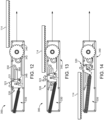
- the loading process begins with the movement assistance mechanism 300 in an unloaded state ( FIG. 12 ), in which the latch mechanism 320 is in its home position.
- the rack member 114 engages the pinion 342 and begins to load the movement assistance mechanism 300 ( FIG. 13 ). More particularly, the rail-mounted rack member 114 causes the pinion 342 to rotate the intermediate gears 344, thereby linearly driving the rack member 346 in the distal direction.
- the rack member 346 pulls the latch mechanism 320 to the intermediate position ( FIG. 13 ), thereby stretching the spring 334 and storing mechanical energy in the biasing mechanism 330.
- the gear ratio of the gear train 340 may be selected such that the force exerted on the spring 334 by the gear train 340 is greater than the force exerted by the user as the user moves the door panel 160 alongside the rack member 114, thereby reducing the force the user is required to exert to load the movement assistance mechanism 300.
- the movement assistance mechanism 300 is able to assist in moving the door assembly 150 to a desired position (e.g., the closed position or the open position).
- a desired position e.g., the closed position or the open position.
- the latch mechanism 320 may engage the opening-side trigger 142 as the door panel 160 approaches the open position, thereby causing the trigger 142 to enter the recess 325.
- the momentum of the door panel 160 causes the trigger 142 to drive the latch mechanism 320 to the release position, at which point the spring 334 releases its mechanical energy and drives the latch mechanism 320 toward its home position, thereby drawing the door panel 160 to the desired open position.
- the jog 363 of the second track 360 engages the third pin 306, thereby driving the latch body 323 to its retracted position and causing the trigger 142 to exit the recess 325.
- the trigger 142 passes alongside the retracted latch body 323.
- the gear ratio of the gear train 340 may be selected such that the force applied to the latch mechanism 320 during such loading is greater than the force applied to the door panel 160 to effect such loading. As a result, the force the user is required to exert in order to load the movement assistance mechanism 300 is reduced.
- the movement assistance mechanism 300 may additionally or alternatively be utilized as the closing assistance mechanism 178 of the closing-side module 170.
- the movement assistance mechanism 300 may additionally or alternatively be utilized as the closing assistance mechanism 178 of the closing-side module 170.
- Those skilled in the art will readily appreciate that a sequence of events analogous to that described above will occur when the movement assistance mechanism 300 is utilized as the closing assistance mechanism 178 of the closing-side module 170.
- the above-described loading of the movement assistance mechanism 300 may occur as the door assembly 150 moves toward its desired position, while in other embodiments, the loading of the movement assistance mechanism 300 may occur as the door assembly 150 moves away from its desired position.
- an assembly or module 400 according to an embodiment not presently claimed.
- the module 400 may, for example, be utilized as the closing-side module 170 of the closure assembly 100, and certain descriptions of the module 400 may be made with specific reference to such an implementation. It is to be appreciated, however, that analogous features and characteristics may be present when a module along the lines of the module 400 is utilized as the opening-side module 180 of the closure assembly 100.
- the module 400 generally includes a bracket 410 configured for mounting to the door panel 160.
- the illustrated module 400 further includes a wheel mechanism 420, a rotary damper 430, a movement assistance mechanism 440, and an anti-jump lug 450, each of which is mounted to the bracket 410.
- the bracket 410 includes a vertical base plate 412 and a pair of horizontal flanges 414 projecting from opposite ends of the base plate 412. Each flange 414 includes one or more fastener openings 415 for receiving fasteners 402 by which the bracket 410 is secured to the door panel 160.
- the base plate 412 includes a recess 416 in which a portion of the rotary damper 430 is seated.
- the base plate 412 also includes a plurality of mounting apertures 413 through which fasteners 404 extend to secure various components of the module 400 to the bracket 410.
- the illustrated wheel mechanism 420 includes a pivot plate 422 that is pivotably mounted to the bracket 410, and which includes a pair of posts 423 projecting therefrom.
- Rotatably mounted on the posts 423 are a pair of wheels 424, each of which includes a circumferential groove 425 operable to receive the rail 128.
- the rotary damper 430 includes a body 432 having a rotatable shaft 434 projecting therefrom. As is known in the art, the body 432 is filled with a fluid that resists rotation of the shaft 434.
- a pinion 436 is coupled to the shaft 434 via a one-way bearing 438 that couples the pinion 436 and the shaft 434 for joint rotation in one rotational direction, while permitting the pinion 436 to rotate relative to the shaft 434 in the opposite rotational direction.
- the pinion 436 is configured to engage the closing-side rack 134 such that the pinion 436 rotates in the first direction as the door assembly 150 approaches the closed position, and rotates in the opposite direction during opening of the door assembly 150.
- the rotary damper 430 slows movement of the door panel 160 as the door assembly 150 approaches the closed position (e.g., under the urging of the movement assistance mechanism 440), and does not resist opening movement of the door assembly 150.
- the movement assistance mechanism 440 includes a housing 442 and a latch mechanism 444 movably mounted to the housing 442, and is configured to assist in the final closing movement of the door assembly 150.
- the movement assistance mechanism 440 is provided in the form of the above-described movement assistance mechanism 200.
- the movement assistance mechanism 440 may be provided in another form, such as that of the force-multiplying movement assistance mechanism 300 of the invention.
- the movement assistance mechanisms 200, 300 are configured to assist in moving the door assembly 150 to a desired position in the manners described above, which need not be repeated herein.
- the anti-jump lug 450 includes a mount plate 452 secured to the bracket 410, a post 454 projecting from the mount plate 452, and a sleeve 456 mounted to the post 454 via a bushing 458 such that the sleeve 456 is rotatable relative to the post 454.
- the anti-jump lug 450 is positioned below the wheels 424 such that the rail 128 is received between the anti-jump lug 450 and the wheels 424, thereby discouraging the module 400 from jumping off the rail 128.
- the system 600 includes a plurality of modular components from which the closure assembly 500 can be assembled in various configurations.
- the system 600 generally includes an assisted closing module 610 and a dampened closing module 620, each of which is operable to be utilized as a closing-side module 502.
- the system 600 further includes an assisted opening module 630 and a dampened opening module 640, each of which is operable to be utilized as the opening-side module 503.
- the system 600 further includes a wheel module 650, which is operable to be utilized as the closing-side module 502, the opening-side module 503, and/or the central module 507.
- the system 600 further includes a biasing module 660 operable to be utilized as the biasing assembly 509.
- the assisted closing module 610 is configured to assist in the final closing movement of the door 501, and to slow such movement of the door 501 to its final closed position.
- the assisted closing module 610 is substantially similar to the above-described closing-side module 170, and similar reference characters are used to indicate similar elements and features.
- the assisted closing module 610 includes a bracket 612 having an anti-jump lug 613 projecting therefrom, a wheel 614 including a circumferential groove 615, a rotary damper 616 including a pinion 617, and a closing assistance mechanism 618 including a latch mechanism 619.
- the bracket 612 may include an anchor 611 operable to engage a tether of the biasing module 660.
- the assisted closing module 610 includes a single wheel 614.
- the assisted closing module 610 may include a dual-wheel mechanism, for example of the type described above with reference to the wheel mechanism 420.
- the rotary damper 616 may be provided as a one-way damper that resists rotation of the pinion 617 in the direction corresponding to closing movement of the door 501 and does not resist rotation of the pinion 617 in the opposite direction corresponding to opening movement of the door 501.
- the closing assistance mechanism 618 may, for example, be provided in the form of the movement assistance mechanism 200, not presently claimed, or that of the force-multiplying movement assistance mechanism 300 of the invention.
- the closing-side module 502 of the closure assembly 500 may be provided in the form of the assisted closing module 610.
- the closing-side engagement zone 505 of closure assembly 500 may include a rack configured to engage the pinion 617 (such as the closing-side rack 134) and a trigger configured to engage the latch mechanism 619 (such as the closing-side trigger 132).
- the closing assistance mechanism 618 may be provided as the movement assistance mechanism 300, and the additional engagement zone 508 may include a rack configured to load the movement assistance mechanism 300 in the manner described above.
- the closing assistance mechanism 618 may be provided as the movement assistance mechanism 200, and the additional engagement zone 508 may not necessarily include such a rack, or may be omitted.
- the dampened closing module 620 includes a bracket 622 having an anti-jump lug 623 projecting therefrom, a wheel 624 including a circumferential groove 625, and a rotary damper 626 including a pinion 627.
- the bracket 622 may include an anchor 621 operable to engage a tether of the biasing module 660.
- the dampened closing module 620 includes a single wheel 624.
- the dampened closing module 620 may include a dual-wheel mechanism, for example of the type described above with reference to the wheel mechanism 420.
- the rotary damper 626 may be provided as a one-way damper that resists rotation of the pinion 627 in the direction corresponding to closing movement of the door 501 and does not resist rotation of the pinion 627 in the opposite direction corresponding to opening movement of the door 501.
- the closing-side module 502 of the closure assembly 500 may be provided in the form of the dampened closing module 620.
- the closing-side engagement zone 505 of closure assembly 500 may include a rack configured to engage the pinion 617 (such as the rack 134), and the trigger may be omitted from the closing-side engagement zone 505.
- the assisted opening module 630 is configured to assist in the final opening movement of the door 501, and to slow such movement of the door 501 to its final open position.
- the assisted opening module 630 is substantially similar to the above-described opening-side module 180, and similar reference characters are used to indicate similar elements and features.
- the assisted opening module 630 includes a bracket 632 having an anti-jump lug 633 projecting therefrom, a wheel 634 including a circumferential groove 635, a rotary damper 636 including a pinion 637, and an opening assistance mechanism 638 including a latch mechanism 639.
- the assisted opening module 630 includes a single wheel 634.
- the assisted opening module 630 may include a dual-wheel mechanism, for example of the type described above with reference to the wheel mechanism 420.
- the rotary damper 636 may be provided as a one-way damper that resists rotation of the pinion 637 in the direction corresponding to opening movement of the door 501 and does not resist rotation of the pinion 637 in the opposite direction corresponding to closing movement of the door 501.
- the opening assistance mechanism 638 may, for example, be provided in the form of the movement assistance mechanism 200, not presently claimed, or that of the movement assistance mechanism 300 of the invention.
- the opening-side module 503 of the closure assembly 500 may be provided in the form of the assisted opening module 630.
- the opening-side engagement zone 506 of closure assembly 500 may include a rack configured to engage the pinion 637 (such as the rack 144) and a trigger configured to engage the latch mechanism 639 (such as the trigger 142).
- the opening assistance mechanism 638 may be provided as the movement assistance mechanism 300, and the additional engagement zone 508 may include a rack configured to load the movement assistance mechanism 300 in the manner described above.
- the opening assistance mechanism 638 may be provided as the movement assistance mechanism 200, and the additional engagement zone 508 may not necessarily include such a rack, or may be omitted.
- the dampened opening module 640 includes a bracket 642 having an anti-jump lug 643 projecting therefrom, a wheel 644 including a circumferential groove 645, and a rotary damper 646 including a pinion 647.
- the dampened opening module 640 includes a single wheel 644.
- the dampened opening module 640 may include a dual-wheel mechanism, for example of the type described above with reference to the wheel mechanism 420.
- the rotary damper 646 may be provided as a one-way damper that resists rotation of the pinion 647 in the direction corresponding to opening movement of the door 501 and does not resist rotation of the pinion 647 in the opposite direction corresponding to closing movement of the door 501.
- the opening-side module 503 of the closure assembly 500 may be provided in the form of the dampened opening module 640.
- the opening-side engagement zone 506 of closure assembly 500 may include a rack configured to engage the pinion 637 (such as the closing-side rack 134), and the trigger may be omitted from the opening-side engagement zone 506.
- the wheel module 650 includes a bracket 652 having an anti-jump lug 653 projecting therefrom, and a wheel 654 including a circumferential groove 655.
- the wheel module 650 includes a single wheel 654.
- the wheel module 650 may include a dual-wheel mechanism, for example of the type described above with reference to the wheel mechanism 420.
- the closing-side module 502 of the closure assembly 500 may be provided in the form of the wheel module 650, and both the trigger and the rack may be omitted from the closing-side engagement zone 505.
- the opening-side module 503 of the closure assembly 500 may be provided in the form of the wheel module 650, and both the trigger and the rack may be omitted from the opening-side engagement zone 506.
- the intermediate module 507 of the closure assembly 500 may be provided in the form of the wheel module 650.
- the rail assembly 504 is provided as two separate pieces having a gap formed therebetween, such an intermediate module 507 may aid in maintaining the door 501 level as the closing-side wheel and/or the opening-side wheel traverse the gap.
- the biasing module 660 includes a housing 662, a spool 664 rotatably mounted in the housing 662, and a tether 666 wrapped about the spool 664.
- a first end of the tether 666 is secured to the spool 664, and an opposite second end 667 of the tether 666 is operable to be secured to the door 501 and/or the closing-side module 502.
- the spool 664 is spring-biased to retract the tether 666.
- the biasing module 660 When included in the closure assembly 500 as the biasing assembly 509, the biasing module 660 is mounted at or near the end of the rail assembly 504 corresponding to the closed position of the door 501, and the end 667 of the tether 666 is secured to the door 501 or the closing-side module 502.
- the tether 666 When the door 501 is moved toward its open position, the tether 666 is unspooled, thereby loading the spring that biases the spool 664 to rotate.
- the spring releases its stored mechanical energy by retracting the tether 666, thereby returning the door 501 toward its closed position.
- each of the closure assemblies is an example of the above-described closure assembly 500, and similar reference characters are used to indicate similar elements and features. While not specifically illustrated in FIGS. 18-25 , it is to be appreciated that each of the closure assemblies may further include a rail assembly corresponding to the above-described rail assembly 504.
- the closing-side module 512 is provided in the form of the dampened closing module 620.
- the closing-side engagement zone of the closure assembly 510 includes a rack configured to engage the pinion of the dampened closing module 620, and need not include a trigger.
- the opening-side module 513 is provided in the form of the wheel module 650.
- the opening-side engagement zone of the closure assembly 510 need not include a rack or a trigger, and may be omitted.
- the closure assembly 510 optionally includes a biasing assembly 519 such as the biasing module 660. It should be appreciated that while a single wheel is illustrated in each of the modules 512, 513, one or both of the modules 512, 513 may include a dual-wheel mechanism.
- the closing-side module 522 is provided in the form of the assisted closing module 610, in which the closing assistance mechanism 618 is provided as the movement assistance mechanism 200.
- the closing-side engagement zone of the closure assembly 520 includes a rack configured to engage the pinion of the assisted closing module 610 and a trigger configured to engage the latch mechanism of the movement assistance mechanism 618, 200.
- the opening-side module 523 is provided in the form of the wheel module 650.
- the opening-side engagement zone of the closure assembly 520 need not include a rack or a trigger, and may be omitted.
- the closure assembly 520 optionally includes a biasing assembly 529 such as the biasing module 660. It should be appreciated that while a single wheel is illustrated in each of the modules 522, 523, one or both of the modules 522, 523 may include a dual-wheel mechanism.
- the closing-side module 532 is provided in the form of the dampened closing module 620.
- the closing-side engagement zone of the closure assembly 530 includes a rack configured to engage the pinion of the dampened closing module 620, and need not include a trigger.
- the opening-side module 533 is provided in the form of the dampened opening module 640.
- the opening-side engagement zone of the closure assembly 530 includes a rack configured to engage the pinion of the dampened opening module 640, and need not include a trigger.
- the closure assembly 530 optionally includes a biasing assembly 539 such as the biasing module 660. It should be appreciated that while a single wheel is illustrated in each of the modules 532, 533, one or both of the modules 532, 533 may include a dual-wheel mechanism.
- the closing-side module 542 is provided in the form of the assisted closing module 610, in which the closing assistance mechanism 618 is provided in the form of the movement assistance mechanism 200.
- the closing-side engagement zone of the closure assembly 540 includes a rack configured to engage the pinion of the assisted closing module 610 and a trigger configured to engage the latch mechanism of the closing assistance mechanism 618, 200.
- the opening-side module 543 is provided in the form of the dampened opening module 640.
- the opening-side engagement zone of the closure assembly 540 includes a rack configured to engage the pinion of the dampened opening module 640, and need not include a trigger.
- the closure assembly 540 optionally includes a biasing assembly 549 such as the biasing module 660. It should be appreciated that while a single wheel is illustrated in each of the modules 542, 543, one or both of the modules 542, 543 may include a dual-wheel mechanism.
- the closing-side module 552 is provided in the form of the assisted closing module 610, in which the closing assistance mechanism 618 is provided in the form of the movement assistance mechanism 200.
- the closing-side engagement zone of the closure assembly 550 includes a rack configured to engage the pinion of the assisted closing module 610 and a trigger configured to engage the latch mechanism of the closing assistance mechanism 618, 200.
- the opening-side module 553 is provided in the form of the assisted opening module 630, in which the opening assistance mechanism 638 is provided in the form of the movement assistance mechanism 200.
- the opening-side engagement zone of the closure assembly 550 includes a rack configured to engage the pinion of the assisted opening module 630 and a trigger configured to engage the latch mechanism of the opening assistance mechanism 638, 200.
- the closure assembly 550 optionally includes a center module 557 in the form of the wheel module 650.
- the closure assembly 550 optionally includes a biasing assembly 559 such as the biasing module 660. It should be appreciated that while a single wheel is illustrated in each of the modules 552, 553, 557, one or more of the modules 552, 553, 557 may include a dual-wheel mechanism.
- the closing-side module 562 is provided in the form of the assisted closing module 610, in which the closing assistance mechanism 618 is provided in the form of the movement assistance mechanism 300.
- the closing-side engagement zone of the closure assembly 560 includes a rack configured to engage the pinion of the assisted closing module 610 and a trigger configured to engage the latch mechanism of the movement assistance mechanism 618, 300.
- the additional engagement zone of the closure assembly 560 includes a rack configured to engage the pinion of the closing assistance mechanism 618, 300.
- the opening-side module 563 is provided in the form of the wheel module 650.
- the opening-side engagement zone of the closure assembly 560 need not include a rack or a trigger, and may be omitted.
- the closure assembly 560 optionally includes a biasing assembly 569 such as the biasing module 660. It should be appreciated that while a single wheel is illustrated in each of the modules 562, 563, one or both of the modules 562, 563 may include a dual-wheel mechanism.
- the closing-side module 572 is provided in the form of the assisted closing module 610, in which the closing assistance mechanism 618 is provided in the form of the movement assistance mechanism 300.
- the closing-side engagement zone of the closure assembly 570 includes a rack configured to engage the pinion of the assisted closing module 610 and a trigger configured to engage the latch mechanism of the closing assistance mechanism 618, 300.
- the additional engagement zone of the closure assembly 560 includes a rack configured to engage the pinion of the closing assistance mechanism 618, 300.
- the opening-side module 573 is provided in the form of the dampened opening module 640.
- the opening-side engagement zone of the closure assembly 570 includes a rack configured to engage the pinion of the dampened opening module 640, and need not include a trigger.
- the closure assembly 570 optionally includes a biasing assembly 579 such as the biasing module 660. It should be appreciated that while a single wheel is illustrated in each of the modules 572, 573, one or both of the modules 572, 573 may include a dual-wheel mechanism.
- the closing-side module 582 is provided in the form of the assisted closing module 610, in which the closing assistance mechanism 618 is provided in the form of the movement assistance mechanism 300.
- the closing-side engagement zone of the closure assembly 580 includes a rack configured to engage the pinion of the assisted closing module 610 and a trigger configured to engage the latch mechanism of the closing assistance mechanism 618, 300.
- the opening-side module 583 is provided in the form of the assisted opening module 630, in which the opening assistance mechanism 638 is provided in the form of the movement assistance mechanism 300.
- the opening-side engagement zone of the closure assembly 580 includes a rack configured to engage the pinion of the assisted opening module 630 and a trigger configured to engage the latch mechanism of the opening assistance mechanism 638, 300.
- the additional engagement zone of the closure assembly 560 may include a rack configured to engage the pinions of each of the closing assistance mechanism 618, 300 and the opening assistance mechanism 638, 300.
- the additional engagement zone of the closure assembly 560 may include a first rack configured to engage the pinion of the closing assistance mechanism 618, 300 and a second rack configured to engage the pinion of the opening assistance mechanism 638, 300.
- the closure assembly 580 optionally includes a center module 587 in the form of the wheel module 650.
- the closure assembly 580 optionally includes a biasing assembly 589 such as the biasing module 660. It should be appreciated that while a single wheel is illustrated in each of the modules 582, 583, 587, one or more of the modules 582, 583, 587 may include a dual-wheel mechanism.
- the modular system 600 is capable of being used to create closure assemblies having varying configurations, such as those described above with reference to FIGS. 18-25 .
Landscapes
- Transmission Devices (AREA)
- Support Devices For Sliding Doors (AREA)
- Power-Operated Mechanisms For Wings (AREA)
Description
- The present disclosure generally relates to sliding door systems, and more particularly but not exclusively relates to top-hung sliding door systems.
- Certain currently available sliding door systems suffer from certain drawbacks and limitations, such as those relating to ease of operation and others. For these reasons among others, there remains a need for further improvements in this technological field.
- The present invention relates to a movement assistance mechanism as defined in
claim 1. Various embodiments of this movement assistance mechanism form the subject-matter of dependent claims 2 to 6. Also claimed is a module as defined in claims 7 to 9, an assembly as defined in claims 10 and 11, as well as a system as defined in claims 12 and 13. -
-
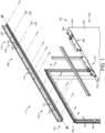
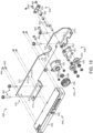
FIG. 1 is an exploded assembly view of a closure assembly according to an embodiment not presently claimed. -
FIG. 2 is a cross-sectional illustration of a rail member of the closure assembly. -
FIG. 3 is a perspective view of a portion of a rail assembly of the closure assembly. -
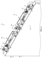
FIG. 4 is a perspective view of a portion of the closure assembly. -
FIG. 5 is a cross-sectional illustration of a portion of the closure assembly. -
FIG. 6 is an exploded assembly view of a movement assistance mechanism according to an example not presently claimed. -
FIG. 7 is a perspective view of a movement assistance mechanism according to an embodiment of the invention. -
FIG. 8 is a cross-sectional view of the movement assistance mechanism ofFIG. 7 . -
FIG. 9 is a plan view of a portion of the movement assistance mechanism illustrated inFIG. 7 with a latch mechanism in an intermediate position. -
FIG. 10 is a plan view of a portion of the movement assistance mechanism illustrated inFIG. 7 with the latch mechanism in a home position. -
FIG. 11 is a plan view of a portion of the movement assistance mechanism illustrated inFIG. 7 with the latch mechanism in a cocked position. -
FIG. 12 illustrates the movement assistance mechanism illustrated inFIG. 7 in an unloaded state. -
FIG. 13 illustrates the movement assistance mechanism illustrated inFIG. 7 in the process of being loaded by a rack member. -
FIG. 14 illustrates the movement assistance mechanism illustrated inFIG. 7 after being loaded by the rack member. -
FIG. 15 is an exploded assembly view of a door module or door assembly according to an embodiment not presently claimed. -
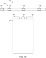
FIG. 16 is a schematic representation of a closure assembly according to certain embodiments of the invention. -
FIG. 17 illustrates a system that may be utilized to generate a closure assembly, according to an embodiment not presently claimed. -
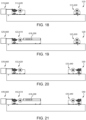
FIGS. 18-25 illustrate various examples and embodiments of closure assemblies generated with the system illustrated inFIG. 17 .FIGS. 23-25 illustrate an embodiment of a closure assembly according to the invention. - With reference to
FIG. 1 , illustrated therein is aclosure assembly 100. - The
closure assembly 100 is mounted to awall 90 having anopening 92 formed therein, and adoorframe 94 is mounted to thewall 90 and defines theopening 92. Theclosure assembly 100 includes arail assembly 110 and adoor assembly 150 movably mounted to therail assembly 110. Thedoor assembly 150 is movable along therail assembly 110 in opposite opening and closing directions between a closed position in which thedoor assembly 150 substantially covers theopening 92 and an open position in which theopening 92 is substantially uncovered by thedoor assembly 150. - The
rail assembly 110 has afirst end portion 111 and asecond end portion 112, and generally includes anelongated rail member 120 and at least one of a closing-side engagement zone 130 or an opening-side engagement zone 140. The closing-side engagement zone 130 is configured to interface with thedoor assembly 150 as thedoor assembly 150 approaches the closed position, and the opening-side engagement zone 140 is configured to interface with thedoor assembly 150 as thedoor assembly 150 approaches the open position. Further details regarding the interaction of thedoor assembly 150 with the closing-side engagement zone 130 and the opening-side engagement zone 140 are provided herein. - With additional reference to
FIG. 2 , therail member 120 includes avertical plate 122 by which therail member 120 is secured to thewall 90 by a plurality offasteners 102 such as screws, a first or upperhorizontal support 124 extending laterally from thevertical plate 122, and a second or lowerhorizontal support 126 positioned below and to the side of the firsthorizontal support 124. Formed near the top of thevertical plate 122 is aflange 123, which may, in certain embodiments, support arack member 114. Thefirst support 124 includes afirst mounting feature 125, and thesecond support 126 includes asecond mounting feature 127 and a longitudinally-extendingrail 128. In the illustrated embodiment, therail 128 is a single continuous rail that extends the length of therail member 120. In other embodiments, therail 128 may be provided as two or more separate rail sections separated by one or more gaps. - With additional reference to
FIG. 3 , the closing-side engagement zone 130 includes a closing-side trigger 132 and a closing-side rack 134, each of which is fixed to therail member 120 in thefirst end portion 111 of therail assembly 110, for example above the opening 92. Thetrigger 132 may be mounted to thefirst support 124 via thefirst mounting feature 125, and therack gear 134 may be mounted to thesecond support 126 via thesecond mounting feature 127. As described herein, therack gear 134 is configured to interface with arotary damper 176 of thedoor assembly 150, and may alternatively be referred to as the closing-side damper rack 134. - In the illustrated form, the opening-
side engagement zone 140 includes an opening-side trigger 142 and an opening-side rack gear 144, each of which is fixed to therail member 120 insecond end portion 112 of therail assembly 110. Thetrigger 142 may be mounted to thefirst support 124 via thefirst mounting feature 125, and therack gear 144 may be mounted to thesecond support 126 via thesecond mounting feature 127. As described herein, therack gear 144 is configured to interface with arotary damper 186 of thedoor assembly 150, and may alternatively be referred to as the opening-side damper rack 144. - With additional reference to
FIG. 4 , the illustrateddoor assembly 150 generally includes adoor panel 160, a closing-side module 170, and an opening-side module 180, and may further include acentral module 190. Thedoor panel 160 includes a closing-sidevertical edge 162, an opening-sidevertical edge 164, a broadvertical face 166, and ahorizontal top edge 168 extending connected to theedges broad face 166. In the illustrated form, each of the closing-side module 170 and the opening-side module 180 is mounted to thetop edge 168. In other forms, one or both of themodules broad face 166. - With additional reference to
FIG. 5 , the closing-side module 170 generally includes aframe 172, ananti-jump lug 173 projecting from theframe 172, awheel 174 rotatably mounted to theframe 172, arotary damper 176 mounted to theframe 172, and amovement assistance mechanism 178 mounted to theframe 172. Thewheel 174 includes agroove 175 in which therail 128 is seated such that therail member 120 supports the closing-side module 170 and thedoor panel 160 to which themodule 170 is mounted. Theanti-jump lug 173 is positioned below therail 128, and hinders themodule 170 from lifting off of therail 128. - The
rotary damper 176 includes apinion gear 177 operable to engage the closing-side rack 134 such that movement of thedoor panel 160 to and from its fully closed position causes therack 134 to rotate thepinion 177 in opposite directions. Therotary damper 176 is configured to resist rotation of thepinion 177 in the direction corresponding to the closing direction of thedoor assembly 150 such that movement of thedoor panel 160 to its fully closed position is resisted by therotary damper 176. In certain forms, therotary damper 176 is provided as a one-wayrotary damper 176 that resists rotation of thepinion 177 in the rotational direction corresponding to closing movement of thedoor assembly 150, but does not resist rotation of thepinion 177 in the rotational direction corresponding to opening movement of thedoor assembly 150. In such forms, movement of thedoor panel 160 from its fully closed position in the opening direction is not resisted by therotary damper 176. - The
movement assistance mechanism 178 includes alatch 179 operable to engage the closing-side trigger 132 as thedoor panel 160 approaches its fully closed position. As described in further detail below, thelatch 179 has a cocked position in which thelatch 179 retains a spring of themovement assistance mechanism 178 in a deformed state in which mechanical energy is stored in the spring. As thedoor assembly 150 approaches the fully closed position, the closing-side trigger 132 engages thelatch 179 and drives thelatch 179 from the cocked position to a release position, thereby causing the spring to release its mechanical energy and draw thedoor panel 160 toward its fully closed position. Further details regarding exemplary forms of themovement assistance mechanism 178 are provided below with reference to themovement assistance mechanism 200, not presently claimed, and the force-multiplyingmovement assistance mechanism 300 of the invention. - While other forms are contemplated, in the illustrated embodiment, the opening-
side module 180 is essentially a mirror image of the closing-side module 180. Thus, the opening-side module 180 generally includes aframe 182, ananti-jump lug 183 projecting from theframe 182, awheel 184 rotatably mounted to theframe 182, arotary damper 186 mounted to theframe 182, and amovement assistance mechanism 188 mounted to theframe 182. Thewheel 184 includes agroove 185 in which therail 128 is seated such that therail member 120 supports the opening-side module 180 and thedoor panel 160 to which themodule 180 is mounted. Theanti-jump lug 183 is positioned below therail 128, and hinders themodule 180 from lifting off of therail 128. - The
rotary damper 186 includes apinion gear 187 operable to engage the opening-side rack 144 such that movement of thedoor assembly 150 to and from its fully open position causes therack 144 to rotate thepinion 187 in opposite directions. Therotary damper 186 is configured to resist rotation of thepinion 187 in the direction corresponding to the opening direction of thedoor assembly 150 such that movement of thedoor panel 160 to its fully open position is resisted by therotary damper 186. In certain forms, therotary damper 186 is provided as a one-wayrotary damper 186 that resists rotation of thepinion 187 in the rotational direction corresponding to open movement of thedoor assembly 150, but does not resist rotation of thepinion 187 in the rotational direction corresponding to closing movement of thedoor assembly 150. In such forms, movement of thedoor panel 160 from its fully open position in the closing direction is not resisted by therotary damper 180. - The
movement assistance mechanism 188 includes alatch 189 operable to engage the opening-side trigger 142 as thedoor assembly 150 approaches its fully open position. As described in further detail below, thelatch 189 has a cocked position in which thelatch 189 retains a spring of themovement assistance mechanism 188 in a deformed state, in which mechanical energy is stored in the spring. As thedoor assembly 150 approaches the fully open position, the opening-side trigger 142 engages thelatch 189 and drives thelatch 189 from the cocked position to a release position, thereby causing the spring to release its mechanical energy and draw thedoor panel 160 toward its fully open position. Further details regarding exemplary forms of themovement assistance mechanism 188 are provided below with reference to themovement assistance mechanism 200, not presently claimed, and the force-multiplyingmovement assistance mechanism 300 of the invention. - The
center module 190 generally includes aframe 192, ananti-jump lug 193 projecting from theframe 192, and awheel 194 rotatably mounted to theframe 192. Thewheel 194 includes agroove 195 in which therail 128 is seated such that therail member 120 supports thecenter module 190 and thedoor 160 to which themodule 190 is mounted. Theanti-jump lug 193 is positioned below therail 128, and hinders themodule 190 from lifting off of therail 128. - With additional reference to
FIG. 6 , illustrated therein is amovement assistance mechanism 200 according to certain examples not presently claimed. Themovement assistance mechanism 200 may, for example, be utilized as the closing-sidemovement assistance mechanism 178 and/or the opening-sidemovement assistance mechanism 188. Themovement assistance mechanism 200 generally includes ahousing 210, alatch mechanism 220 movably mounted to thehousing 210, and abiasing mechanism 230 connected between thehousing 210 and thelatch mechanism 220. - The
housing 210 includes afirst portion 211 and asecond portion 212 that are coupled to one another to define aninternal chamber 213 in which thebiasing mechanism 230 is mounted, and achannel 214 through which thelatch mechanism 220 projects. Thefirst portion 211 also defines atrack 216 having astraight portion 217 and anangled jog 218, and thesecond portion 212 defines a mirror image track facing thetrack 216. - The
latch mechanism 220 includes a body portion 222, first andsecond arms recess 225 therebetween, and afinger 228 projecting from an opposite second side of the body portion 222. Thelatch mechanism 220 is slidably mounted to thehousing 210 by afirst pivot pin 202 and asecond pivot pin 204, each of which projects into thetracks 216 such that thehousing 210 movably supports thelatch mechanism 220 and guides thelatch mechanism 220 along the path defined by thetracks 216. - The
biasing mechanism 230 includes abase 232 and aspring 234 having afirst end 235 and an oppositesecond end 236. Thefirst end 235 is coupled to thebase 232, which is pivotably mounted to thehousing 210. Thesecond end 236 is coupled to thefinger 228 such that thespring 234 biases thelatch mechanism 220 toward a home position. - The
latch mechanism 220 is biased toward a home position by thebiasing mechanism 230, and is movable to a cocked position in which thebiasing mechanism 230 is loaded such that mechanical energy is stored in thespring 234. With thelatch mechanism 220 in the home position, each of the pivot pins 202, 204 is received in thestraight portion 217 of thetrack 216. Movement of thelatch mechanism 220 toward the cocked position stretches thespring 234, thereby loading thebiasing mechanism 230 and storing mechanical energy in thespring 234. With thelatch mechanism 220 in the cocked position, thefirst pivot pin 202 is received in theangled jog 218. Thejog 218 retains thelatch mechanism 220 in the cocked position against the biasing force of thespring 234, which urges thelatch mechanism 220 toward its home position. - As noted above, the
movement assistance mechanism 200 may be utilized as theclosing assistance mechanism 178 of the closing-side module 170. In such forms, themovement assistance mechanism 200 cooperates with the closing-side engagement zone 130 to assist movement of thedoor assembly 150 toward its fully closed position. When thedoor assembly 150 is in its fully closed position, thelatch mechanism 220 is in its home position, and the closing-side trigger 132 is received in therecess 225. As thedoor assembly 150 moves toward its open position under the manual force of a user, the closing-side trigger 132 engages thesecond arm 226 and drives thelatch mechanism 220 to its cocked position, thereby stretching thespring 234. During this movement, therotary damper 176 travels along the closing-side rack 134, thereby rotating thepinion 177 in the direction corresponding to opening movement of thedoor assembly 150. In examples, not presently claimed, in which therotary damper 176 is provided as a unidirectional or one-way damper, this rotation of thepinion 177 is not resisted by thedamper 176, such that thedamper 176 does not add to the force required to move thedoor assembly 150 from the fully closed position. As thedoor assembly 150 travels toward its open position, thelatch mechanism 220 travels to its cocked position, at which point thetrigger 132 exits therecess 225. Thelatch mechanism 220 is retained in the cocked position by engagement between thejog 218 and thepin 202. - When the
door assembly 150 is subsequently moved toward its closed position, the closing-side trigger 132 engages thefirst arm 224 to pivot thelatch mechanism 220 to a release position, thereby causing thepin 202 to exit thejog 218. With thepin 202 removed from thejog 218, thespring 234 drives thelatch mechanism 220 toward its home position, thereby pulling thedoor panel 160 toward its fully closed position. As a result, themovement assistance mechanism 200 aids in the final closing movement of thedoor panel 160 when utilized as theclosing assistance mechanism 178 of the closing-side module 170. It should be appreciated that this final closing movement is slowed by therotary damper 176, thepinion 177 of which engages the closing-side rack 134 during the closing movement of thedoor assembly 150. Due to the fact that therotary damper 176 resists rotation of the pinion in the direction corresponding to closing movement of thedoor assembly 150, engagement between thedamper 176 and therack 134 slows the final closing movement of thedoor assembly 150. - As noted above, the
movement assistance mechanism 200 may additionally or alternatively be utilized as theopening assistance mechanism 188 of the opening-side module 180. Those skilled in the art will readily recognize that in such examples, not presently claimed, themovement assistance mechanism 200 will cooperate with the opening-side engagement zone 140 to assist movement of thedoor assembly 150 toward the fully open position in a manner analogous to that described above with reference to the use of themovement assistance mechanism 200 as theclosing assistance mechanism 178 of the closing-side module 170. Additionally, the final opening movement of thedoor assembly 150 will be slowed by engagement between the opening-side damper 186 and the opening-side rack 144 in a manner analogous to that described above with reference to the closing-side damper 176 and the closing-side rack 134. - With additional reference to
FIGS. 7-9 , illustrated therein is amovement assistance mechanism 300 according to an embodiment of the invention. Themovement assistance mechanism 300 may, for example, be utilized as the closing-sidemovement assistance mechanism 178 and/or the opening-sidemovement assistance mechanism 188. Themovement assistance mechanism 300 includes ahousing 310, alatch mechanism 320 movably mounted to thehousing 310, abiasing mechanism 330 connected between thehousing 310 and thelatch mechanism 320, and agear train 340 connected with thelatch mechanism 320. - The
housing 310 includes afirst portion 311 and asecond portion 312 that are coupled to one another to define an internal chamber 313 in which thebiasing mechanism 330 is mounted, and achannel 314 through which a portion of thelatch mechanism 320 projects. As illustrated inFIG. 9 , thehousing 310 defines afirst track 350 and asecond track 360 proximate thefirst track 350, further details of which are provided below. Each of thefirst track 350 and thesecond track 360 includes a first run formed in thefirst portion 311, and includes a mirror image second run formed in thesecond portion 312. - The
latch mechanism 320 includes acarriage 321 movably mounted to thehousing 310 and alatch body 323 movably mounted to thecarriage 321. Thecarriage 321 includes alateral slot 322, and is movably coupled to thehousing 310 by afirst pin 302 and asecond pin 304. Each of thepins first track 350 such that thehousing 310 constrains movement of thecarriage 321 to the path defined by thefirst track 350. Thelatch body 323 includes abody portion 327 and ahead 328 formed on one end of thebody portion 327. One end of thebody portion 327 is movably coupled with thecarriage 321 and thehousing 310 by athird pin 306, which extends through thelateral slot 322. Thepin 306 also extends into thesecond track 360 such that thehousing 310 constrains movement of the latch body to the path defined by thesecond track 360. In the illustrated form, thepins latch mechanism 320. In other embodiments, one or more of thepins latch mechanism 320. Thebody portion 327 of thelatch body 323 extends through a gap formed between the first andsecond pins head 328, which includes first andsecond arms recess 325 defined therebetween. - The
biasing mechanism 330 includes aspring 334 having afirst end 335 and an oppositesecond end 336. Thefirst end 335 is coupled to thehousing 310, and thesecond end 336 is coupled to thecarriage 321 such that thespring 334 biases thelatch mechanism 320 toward a home position (to the left inFIG. 8 ). - The
gear train 340 is movably mounted to thehousing 310, and generally includes apinion gear 342, aninput gear 343 rotationally coupled with thepinion gear 342, one or moreintermediate gears 344 operably engaged with theinput gear 343, and arack member 346 including arack gear 347 engaged with theinput gear 343 via the one or moreintermediate gears 344. Thepinion gear 342 is mounted to the exterior of thehousing 310 such that thepinion gear 342 is operable to engage therack gear 114 as thedoor assembly 150 moves between its open position and its closed position. The one or moreintermediate gears 344 operably couple therack member 346 with theinput gear 343 such that rotation of thepinion gear 342 causes a corresponding longitudinal movement of therack member 346. Therack member 346 includes anarm 348 defining anaperture 349, and apin 306 extends through thecarriage 321 and into theaperture 349, thereby operably coupling therack member 346 with thelatch mechanism 320. As a result, rotation of thepinion gear 342 in one rotational direction causes therack member 346 to pull thelatch mechanism 320 to the cocked position, thereby stretching and storing mechanical energy in thespring 334. - The
first track 350 includes aproximal end portion 352, an oppositedistal end portion 354, and anintermediate portion 356 extending between and connecting theproximal end portion 352 and thedistal end portion 354. Each of theproximal end portion 352 and theintermediate portion 356 extends substantially parallel to alongitudinal axis 301 of themovement assistance mechanism 300, and thedistal end portion 354 defines anangled jog 355 that extends laterally inward (i.e., away from the channel 314). - The
second track 360 includes aproximal end portion 362, an oppositedistal end portion 364, and anintermediate portion 366 extending between and connecting theproximal end portion 362 and thedistal end portion 364. Theintermediate portion 366 extends substantially parallel to thelongitudinal axis 301, theproximal end portion 362 defines a secondangled jog 363 extending away from thechannel 314, and thedistal end portion 364 defines arecess 365 extending away from thechannel 314. -
FIG. 9 illustrates thelatch mechanism 320 in an intermediate position between the cocked position and the home position. In the intermediate position, each of thefirst pin 302 and thesecond pin 304 is received in theintermediate portion 356 of thefirst track 350, such that thecarriage 321 is substantially straight relative to thehousing 310. Additionally, thethird pin 306 is received in theintermediate portion 366 of thesecond track 360 such that thelatch body 323 has an extended position relative to thecarriage 321. From the intermediate position, thelatch mechanism 320 is operable to move proximally toward the home position (FIG. 10 ) or distally toward the cocked position (FIG. 11 ). - With additional reference to
FIG. 10 , proximal movement of thelatch mechanism 320 from the intermediate position (FIG. 9 ) to the home position (FIG. 10 ) causes thethird pin 306 to travel into thejog 363 defined by theproximal end portion 362 of thesecond track 360. Thejog 363 urges thepin 306 laterally inward, thereby moving thelatch body 323 to a retracted position relative to thecarriage 321. - With additional reference to
FIG. 11 , distal movement of thelatch mechanism 320 from the intermediate position (FIG. 9 ) to the cocked position (FIG. 11 ) causes thefirst pin 302 to enter theangled jog 355 defined by thedistal end portion 354 of thefirst track 350, thereby angling thelatch mechanism 320 relative to thehousing 310. In this state, thejog 355 and/or therecess 365 retains thelatch mechanism 320 in the cocked position against the biasing force exerted by thespring 334. - With additional reference to
FIGS. 12-14 , themovement assistance mechanism 300 is configured to interface with therack member 114 such that movement of themovement assistance mechanism 300 along therail assembly 110 cocks thelatch mechanism 320, thereby loading themovement assistance mechanism 300. The loading process begins with themovement assistance mechanism 300 in an unloaded state (FIG. 12 ), in which thelatch mechanism 320 is in its home position. As thedoor panel 160 travels alongside the rail-mountedrack member 114, therack member 114 engages thepinion 342 and begins to load the movement assistance mechanism 300 (FIG. 13 ). More particularly, the rail-mountedrack member 114 causes thepinion 342 to rotate theintermediate gears 344, thereby linearly driving therack member 346 in the distal direction. As a result, therack member 346 pulls thelatch mechanism 320 to the intermediate position (FIG. 13 ), thereby stretching thespring 334 and storing mechanical energy in thebiasing mechanism 330. - As the
door panel 160 continues to travel alongside the rail-mountedrack member 114, therack member 114 continues to rotate thepinion 342, thereby continuing the loading ofmovement assistance mechanism 300. The gear ratio of thegear train 340 may be selected such that the force exerted on thespring 334 by thegear train 340 is greater than the force exerted by the user as the user moves thedoor panel 160 alongside therack member 114, thereby reducing the force the user is required to exert to load themovement assistance mechanism 300. When the movement assistance mechanism is fully loaded (FIG. 14 ), thelatch mechanism 320 is retained in the cocked position by thejog 355 of thefirst track 350. - Once fully loaded (
FIG. 14 ), themovement assistance mechanism 300 is able to assist in moving thedoor assembly 150 to a desired position (e.g., the closed position or the open position). For example, in embodiments in which themovement assistance mechanism 300 is utilized as theopening assistance mechanism 188 of the opening-side module 180, thelatch mechanism 320 may engage the opening-side trigger 142 as thedoor panel 160 approaches the open position, thereby causing thetrigger 142 to enter therecess 325. The momentum of thedoor panel 160 causes thetrigger 142 to drive thelatch mechanism 320 to the release position, at which point thespring 334 releases its mechanical energy and drives thelatch mechanism 320 toward its home position, thereby drawing thedoor panel 160 to the desired open position. As thelatch mechanism 320 approaches its home position, thejog 363 of thesecond track 360 engages thethird pin 306, thereby driving thelatch body 323 to its retracted position and causing thetrigger 142 to exit therecess 325. - When the
door assembly 150 is subsequently urged from the open position toward the closed position, thetrigger 142 passes alongside the retractedlatch body 323. As a result, the user need not return thelatch mechanism 320 to its cocked position against the force of thespring 334. Instead, such return is accomplished by the above-described engagement between thegear train 340 and therack 114. As noted above, the gear ratio of thegear train 340 may be selected such that the force applied to thelatch mechanism 320 during such loading is greater than the force applied to thedoor panel 160 to effect such loading. As a result, the force the user is required to exert in order to load themovement assistance mechanism 300 is reduced. - As noted above, the
movement assistance mechanism 300 may additionally or alternatively be utilized as theclosing assistance mechanism 178 of the closing-side module 170. Those skilled in the art will readily appreciate that a sequence of events analogous to that described above will occur when themovement assistance mechanism 300 is utilized as theclosing assistance mechanism 178 of the closing-side module 170. - In certain embodiments, the above-described loading of the
movement assistance mechanism 300 may occur as thedoor assembly 150 moves toward its desired position, while in other embodiments, the loading of themovement assistance mechanism 300 may occur as thedoor assembly 150 moves away from its desired position. - With additional reference to
FIG. 15 , illustrated therein is an assembly ormodule 400 according to an embodiment not presently claimed. - The
module 400 may, for example, be utilized as the closing-side module 170 of theclosure assembly 100, and certain descriptions of themodule 400 may be made with specific reference to such an implementation. It is to be appreciated, however, that analogous features and characteristics may be present when a module along the lines of themodule 400 is utilized as the opening-side module 180 of theclosure assembly 100. In the illustrated form, themodule 400 generally includes abracket 410 configured for mounting to thedoor panel 160. The illustratedmodule 400 further includes awheel mechanism 420, arotary damper 430, amovement assistance mechanism 440, and ananti-jump lug 450, each of which is mounted to thebracket 410. - The
bracket 410 includes avertical base plate 412 and a pair ofhorizontal flanges 414 projecting from opposite ends of thebase plate 412. Eachflange 414 includes one ormore fastener openings 415 for receivingfasteners 402 by which thebracket 410 is secured to thedoor panel 160. Thebase plate 412 includes arecess 416 in which a portion of therotary damper 430 is seated. Thebase plate 412 also includes a plurality of mountingapertures 413 through whichfasteners 404 extend to secure various components of themodule 400 to thebracket 410. - The illustrated
wheel mechanism 420 includes apivot plate 422 that is pivotably mounted to thebracket 410, and which includes a pair ofposts 423 projecting therefrom. Rotatably mounted on theposts 423 are a pair ofwheels 424, each of which includes acircumferential groove 425 operable to receive therail 128. - The
rotary damper 430 includes abody 432 having arotatable shaft 434 projecting therefrom. As is known in the art, thebody 432 is filled with a fluid that resists rotation of theshaft 434. Apinion 436 is coupled to theshaft 434 via a one-way bearing 438 that couples thepinion 436 and theshaft 434 for joint rotation in one rotational direction, while permitting thepinion 436 to rotate relative to theshaft 434 in the opposite rotational direction. Thepinion 436 is configured to engage the closing-side rack 134 such that thepinion 436 rotates in the first direction as thedoor assembly 150 approaches the closed position, and rotates in the opposite direction during opening of thedoor assembly 150. As a result, therotary damper 430 slows movement of thedoor panel 160 as thedoor assembly 150 approaches the closed position (e.g., under the urging of the movement assistance mechanism 440), and does not resist opening movement of thedoor assembly 150. - The
movement assistance mechanism 440 includes ahousing 442 and alatch mechanism 444 movably mounted to thehousing 442, and is configured to assist in the final closing movement of thedoor assembly 150. In the illustrated example, not presently claimed, themovement assistance mechanism 440 is provided in the form of the above-describedmovement assistance mechanism 200. In other examples and embodiments, themovement assistance mechanism 440 may be provided in another form, such as that of the force-multiplyingmovement assistance mechanism 300 of the invention. Themovement assistance mechanisms door assembly 150 to a desired position in the manners described above, which need not be repeated herein. - The
anti-jump lug 450 includes amount plate 452 secured to thebracket 410, apost 454 projecting from themount plate 452, and asleeve 456 mounted to thepost 454 via a bushing 458 such that thesleeve 456 is rotatable relative to thepost 454. In a manner similar to that described above with reference to theanti-jump lug 173, theanti-jump lug 450 is positioned below thewheels 424 such that therail 128 is received between theanti-jump lug 450 and thewheels 424, thereby discouraging themodule 400 from jumping off therail 128. - With additional reference to
FIG. 16 , illustrated therein is a schematic representation of aclosure assembly 500 according to certain embodiments. Theclosure assembly 500 includes adoor panel 501 movable between a closed position (to the left inFIG. 16 ) and an open position (to the right inFIG. 16 ), a closing-side module 502, anopening side module 503, and arail assembly 504 including at least one of a closing-side engagement zone 505 or an opening-side engagement zone 506. Theclosure assembly 500 may further include one or more of anintermediate module 507, anadditional engagement zone 508, or a biasingassembly 509 urging thedoor panel 501 toward the closed position. - With additional reference to
FIG. 17 , illustrated therein is asystem 600 according to an embodiment not presently claimed. As described herein, thesystem 600 includes a plurality of modular components from which theclosure assembly 500 can be assembled in various configurations. Thesystem 600 generally includes an assistedclosing module 610 and a dampenedclosing module 620, each of which is operable to be utilized as a closing-side module 502. Thesystem 600 further includes an assistedopening module 630 and a dampenedopening module 640, each of which is operable to be utilized as the opening-side module 503. Thesystem 600 further includes awheel module 650, which is operable to be utilized as the closing-side module 502, the opening-side module 503, and/or thecentral module 507. Thesystem 600 further includes abiasing module 660 operable to be utilized as the biasingassembly 509. - The assisted
closing module 610 is configured to assist in the final closing movement of thedoor 501, and to slow such movement of thedoor 501 to its final closed position. The assistedclosing module 610 is substantially similar to the above-described closing-side module 170, and similar reference characters are used to indicate similar elements and features. Thus, the assistedclosing module 610 includes abracket 612 having ananti-jump lug 613 projecting therefrom, awheel 614 including acircumferential groove 615, arotary damper 616 including apinion 617, and aclosing assistance mechanism 618 including alatch mechanism 619. Thebracket 612 may include ananchor 611 operable to engage a tether of thebiasing module 660. In the illustrated form, the assistedclosing module 610 includes asingle wheel 614. In other embodiments, the assistedclosing module 610 may include a dual-wheel mechanism, for example of the type described above with reference to thewheel mechanism 420. Therotary damper 616 may be provided as a one-way damper that resists rotation of thepinion 617 in the direction corresponding to closing movement of thedoor 501 and does not resist rotation of thepinion 617 in the opposite direction corresponding to opening movement of thedoor 501. Theclosing assistance mechanism 618 may, for example, be provided in the form of themovement assistance mechanism 200, not presently claimed, or that of the force-multiplyingmovement assistance mechanism 300 of the invention. - The closing-
side module 502 of theclosure assembly 500 may be provided in the form of the assistedclosing module 610. In such embodiments, the closing-side engagement zone 505 ofclosure assembly 500 may include a rack configured to engage the pinion 617 (such as the closing-side rack 134) and a trigger configured to engage the latch mechanism 619 (such as the closing-side trigger 132). In certain embodiments, theclosing assistance mechanism 618 may be provided as themovement assistance mechanism 300, and theadditional engagement zone 508 may include a rack configured to load themovement assistance mechanism 300 in the manner described above. In other examples not presently claimed, theclosing assistance mechanism 618 may be provided as themovement assistance mechanism 200, and theadditional engagement zone 508 may not necessarily include such a rack, or may be omitted. - The dampened
closing module 620 includes abracket 622 having ananti-jump lug 623 projecting therefrom, awheel 624 including acircumferential groove 625, and arotary damper 626 including apinion 627. Thebracket 622 may include ananchor 621 operable to engage a tether of thebiasing module 660. In the illustrated form, the dampenedclosing module 620 includes asingle wheel 624. In other embodiments, the dampenedclosing module 620 may include a dual-wheel mechanism, for example of the type described above with reference to thewheel mechanism 420. Therotary damper 626 may be provided as a one-way damper that resists rotation of thepinion 627 in the direction corresponding to closing movement of thedoor 501 and does not resist rotation of thepinion 627 in the opposite direction corresponding to opening movement of thedoor 501. - The closing-
side module 502 of theclosure assembly 500 may be provided in the form of the dampenedclosing module 620. In such embodiments, the closing-side engagement zone 505 ofclosure assembly 500 may include a rack configured to engage the pinion 617 (such as the rack 134), and the trigger may be omitted from the closing-side engagement zone 505. - The assisted
opening module 630 is configured to assist in the final opening movement of thedoor 501, and to slow such movement of thedoor 501 to its final open position. The assistedopening module 630 is substantially similar to the above-described opening-side module 180, and similar reference characters are used to indicate similar elements and features. Thus, the assistedopening module 630 includes abracket 632 having ananti-jump lug 633 projecting therefrom, awheel 634 including acircumferential groove 635, arotary damper 636 including apinion 637, and anopening assistance mechanism 638 including alatch mechanism 639. In the illustrated form, the assistedopening module 630 includes asingle wheel 634. In other embodiments, the assistedopening module 630 may include a dual-wheel mechanism, for example of the type described above with reference to thewheel mechanism 420. Therotary damper 636 may be provided as a one-way damper that resists rotation of thepinion 637 in the direction corresponding to opening movement of thedoor 501 and does not resist rotation of thepinion 637 in the opposite direction corresponding to closing movement of thedoor 501. Theopening assistance mechanism 638 may, for example, be provided in the form of themovement assistance mechanism 200, not presently claimed, or that of themovement assistance mechanism 300 of the invention. - The opening-
side module 503 of theclosure assembly 500 may be provided in the form of the assistedopening module 630. In such embodiments, the opening-side engagement zone 506 ofclosure assembly 500 may include a rack configured to engage the pinion 637 (such as the rack 144) and a trigger configured to engage the latch mechanism 639 (such as the trigger 142). In certain embodiments of the invention, theopening assistance mechanism 638 may be provided as themovement assistance mechanism 300, and theadditional engagement zone 508 may include a rack configured to load themovement assistance mechanism 300 in the manner described above. In other examples not presently claimed, theopening assistance mechanism 638 may be provided as themovement assistance mechanism 200, and theadditional engagement zone 508 may not necessarily include such a rack, or may be omitted. - The dampened
opening module 640 includes abracket 642 having ananti-jump lug 643 projecting therefrom, awheel 644 including acircumferential groove 645, and arotary damper 646 including apinion 647. In the illustrated form, the dampenedopening module 640 includes asingle wheel 644. In other embodiments, the dampenedopening module 640 may include a dual-wheel mechanism, for example of the type described above with reference to thewheel mechanism 420. Therotary damper 646 may be provided as a one-way damper that resists rotation of thepinion 647 in the direction corresponding to opening movement of thedoor 501 and does not resist rotation of thepinion 647 in the opposite direction corresponding to closing movement of thedoor 501. - The opening-
side module 503 of theclosure assembly 500 may be provided in the form of the dampenedopening module 640. In such embodiments, the opening-side engagement zone 506 ofclosure assembly 500 may include a rack configured to engage the pinion 637 (such as the closing-side rack 134), and the trigger may be omitted from the opening-side engagement zone 506. - The
wheel module 650 includes abracket 652 having ananti-jump lug 653 projecting therefrom, and awheel 654 including acircumferential groove 655. In the illustrated form, thewheel module 650 includes asingle wheel 654. In other embodiments, thewheel module 650 may include a dual-wheel mechanism, for example of the type described above with reference to thewheel mechanism 420. - In certain embodiments, the closing-
side module 502 of theclosure assembly 500 may be provided in the form of thewheel module 650, and both the trigger and the rack may be omitted from the closing-side engagement zone 505. Alternatively, the opening-side module 503 of theclosure assembly 500 may be provided in the form of thewheel module 650, and both the trigger and the rack may be omitted from the opening-side engagement zone 506. In certain embodiments, theintermediate module 507 of theclosure assembly 500 may be provided in the form of thewheel module 650. For example, in embodiments in which therail assembly 504 is provided as two separate pieces having a gap formed therebetween, such anintermediate module 507 may aid in maintaining thedoor 501 level as the closing-side wheel and/or the opening-side wheel traverse the gap. - The
biasing module 660 includes ahousing 662, aspool 664 rotatably mounted in thehousing 662, and atether 666 wrapped about thespool 664. A first end of thetether 666 is secured to thespool 664, and an opposite second end 667 of thetether 666 is operable to be secured to thedoor 501 and/or the closing-side module 502. Thespool 664 is spring-biased to retract thetether 666. When included in theclosure assembly 500 as the biasingassembly 509, thebiasing module 660 is mounted at or near the end of therail assembly 504 corresponding to the closed position of thedoor 501, and the end 667 of thetether 666 is secured to thedoor 501 or the closing-side module 502. When thedoor 501 is moved toward its open position, thetether 666 is unspooled, thereby loading the spring that biases thespool 664 to rotate. When thedoor 501 is released, the spring releases its stored mechanical energy by retracting thetether 666, thereby returning thedoor 501 toward its closed position. - With additional reference to
FIGS. 18-25 , illustrated therein are certain non-limiting embodiments of closure assemblies. Each of the closure assemblies is an example of the above-describedclosure assembly 500, and similar reference characters are used to indicate similar elements and features. While not specifically illustrated inFIGS. 18-25 , it is to be appreciated that each of the closure assemblies may further include a rail assembly corresponding to the above-describedrail assembly 504. - With reference to
FIG. 18 , illustrated therein is aclosure assembly 510 according to certain examples not presently claimed. The closing-side module 512 is provided in the form of the dampenedclosing module 620. The closing-side engagement zone of theclosure assembly 510 includes a rack configured to engage the pinion of the dampenedclosing module 620, and need not include a trigger. The opening-side module 513 is provided in the form of thewheel module 650. The opening-side engagement zone of theclosure assembly 510 need not include a rack or a trigger, and may be omitted. Theclosure assembly 510 optionally includes a biasing assembly 519 such as thebiasing module 660. It should be appreciated that while a single wheel is illustrated in each of the modules 512, 513, one or both of the modules 512, 513 may include a dual-wheel mechanism. - With reference to
FIG. 19 , illustrated therein is aclosure assembly 520 according to certain examples not presently claimed. The closing-side module 522 is provided in the form of the assistedclosing module 610, in which theclosing assistance mechanism 618 is provided as themovement assistance mechanism 200. The closing-side engagement zone of theclosure assembly 520 includes a rack configured to engage the pinion of the assistedclosing module 610 and a trigger configured to engage the latch mechanism of themovement assistance mechanism wheel module 650. The opening-side engagement zone of theclosure assembly 520 need not include a rack or a trigger, and may be omitted. Theclosure assembly 520 optionally includes a biasing assembly 529 such as thebiasing module 660. It should be appreciated that while a single wheel is illustrated in each of the modules 522, 523, one or both of the modules 522, 523 may include a dual-wheel mechanism. - With reference to
FIG. 20 , illustrated therein is aclosure assembly 530 according to certain examples not presently claimed. The closing-side module 532 is provided in the form of the dampenedclosing module 620. The closing-side engagement zone of theclosure assembly 530 includes a rack configured to engage the pinion of the dampenedclosing module 620, and need not include a trigger. The opening-side module 533 is provided in the form of the dampenedopening module 640. The opening-side engagement zone of theclosure assembly 530 includes a rack configured to engage the pinion of the dampenedopening module 640, and need not include a trigger. Theclosure assembly 530 optionally includes a biasing assembly 539 such as thebiasing module 660. It should be appreciated that while a single wheel is illustrated in each of the modules 532, 533, one or both of the modules 532, 533 may include a dual-wheel mechanism. - With reference to
FIG. 21 , illustrated therein is aclosure assembly 540 according to certain examples not presently claimed. The closing-side module 542 is provided in the form of the assistedclosing module 610, in which theclosing assistance mechanism 618 is provided in the form of themovement assistance mechanism 200. The closing-side engagement zone of theclosure assembly 540 includes a rack configured to engage the pinion of the assistedclosing module 610 and a trigger configured to engage the latch mechanism of theclosing assistance mechanism opening module 640. The opening-side engagement zone of theclosure assembly 540 includes a rack configured to engage the pinion of the dampenedopening module 640, and need not include a trigger. Theclosure assembly 540 optionally includes a biasing assembly 549 such as thebiasing module 660. It should be appreciated that while a single wheel is illustrated in each of the modules 542, 543, one or both of the modules 542, 543 may include a dual-wheel mechanism. - With reference to
FIG. 22 , illustrated therein is aclosure assembly 550 according to certain examples not presently claimed. The closing-side module 552 is provided in the form of the assistedclosing module 610, in which theclosing assistance mechanism 618 is provided in the form of themovement assistance mechanism 200. The closing-side engagement zone of theclosure assembly 550 includes a rack configured to engage the pinion of the assistedclosing module 610 and a trigger configured to engage the latch mechanism of theclosing assistance mechanism opening module 630, in which theopening assistance mechanism 638 is provided in the form of themovement assistance mechanism 200. The opening-side engagement zone of theclosure assembly 550 includes a rack configured to engage the pinion of the assistedopening module 630 and a trigger configured to engage the latch mechanism of theopening assistance mechanism closure assembly 550 optionally includes a center module 557 in the form of thewheel module 650. Theclosure assembly 550 optionally includes a biasing assembly 559 such as thebiasing module 660. It should be appreciated that while a single wheel is illustrated in each of the modules 552, 553, 557, one or more of the modules 552, 553, 557 may include a dual-wheel mechanism. - With reference to
FIG. 23 , illustrated therein is aclosure assembly 560 according to an embodiment of the invention. The closing-side module 562 is provided in the form of the assistedclosing module 610, in which theclosing assistance mechanism 618 is provided in the form of themovement assistance mechanism 300. The closing-side engagement zone of theclosure assembly 560 includes a rack configured to engage the pinion of the assistedclosing module 610 and a trigger configured to engage the latch mechanism of themovement assistance mechanism closure assembly 560 includes a rack configured to engage the pinion of theclosing assistance mechanism wheel module 650. The opening-side engagement zone of theclosure assembly 560 need not include a rack or a trigger, and may be omitted. Theclosure assembly 560 optionally includes a biasing assembly 569 such as thebiasing module 660. It should be appreciated that while a single wheel is illustrated in each of the modules 562, 563, one or both of the modules 562, 563 may include a dual-wheel mechanism. - With reference to
FIG. 24 , illustrated therein is aclosure assembly 570 according to an embodiment of the invention. The closing-side module 572 is provided in the form of the assistedclosing module 610, in which theclosing assistance mechanism 618 is provided in the form of themovement assistance mechanism 300. The closing-side engagement zone of theclosure assembly 570 includes a rack configured to engage the pinion of the assistedclosing module 610 and a trigger configured to engage the latch mechanism of theclosing assistance mechanism closure assembly 560 includes a rack configured to engage the pinion of theclosing assistance mechanism opening module 640. The opening-side engagement zone of theclosure assembly 570 includes a rack configured to engage the pinion of the dampenedopening module 640, and need not include a trigger. Theclosure assembly 570 optionally includes a biasing assembly 579 such as thebiasing module 660. It should be appreciated that while a single wheel is illustrated in each of the modules 572, 573, one or both of the modules 572, 573 may include a dual-wheel mechanism. - With reference to
FIG. 25 , illustrated therein is aclosure assembly 580 according to an embodiment of the invention. The closing-side module 582 is provided in the form of the assistedclosing module 610, in which theclosing assistance mechanism 618 is provided in the form of themovement assistance mechanism 300. The closing-side engagement zone of theclosure assembly 580 includes a rack configured to engage the pinion of the assistedclosing module 610 and a trigger configured to engage the latch mechanism of theclosing assistance mechanism opening module 630, in which theopening assistance mechanism 638 is provided in the form of themovement assistance mechanism 300. The opening-side engagement zone of theclosure assembly 580 includes a rack configured to engage the pinion of the assistedopening module 630 and a trigger configured to engage the latch mechanism of theopening assistance mechanism closure assembly 560 may include a rack configured to engage the pinions of each of theclosing assistance mechanism opening assistance mechanism closure assembly 560 may include a first rack configured to engage the pinion of theclosing assistance mechanism opening assistance mechanism closure assembly 580 optionally includes a center module 587 in the form of thewheel module 650. Theclosure assembly 580 optionally includes a biasing assembly 589 such as thebiasing module 660. It should be appreciated that while a single wheel is illustrated in each of the modules 582, 583, 587, one or more of the modules 582, 583, 587 may include a dual-wheel mechanism. - As should be evident from the foregoing, the
modular system 600 is capable of being used to create closure assemblies having varying configurations, such as those described above with reference toFIGS. 18-25 . - While certain exemplary forms of closure assemblies and modules have been described herein, it is to be appreciated that various modifications of the described subject matter are also considered within the scope of the subject matter set forth herein. For example, while the embodiments set forth herein generally describe a first member mounted to the door and a cooperating second member mounted to the rail assembly, it is also contemplated that these positions may be reversed. Thus, while the embodiments set forth hereinabove generally involve providing a rotary damper to the door and a cooperating rack to the rail assembly, it should be appreciated that the rotary damper may instead be mounted to the rail assembly, and that the cooperating rack member may be mounted to the door. Similarly, while certain embodiments involve a movement assistance mechanism mounted to the door and a cooperating trigger mounted to the rail assembly, it should be appreciated that the movement assistance mechanism may instead be mounted to the rail assembly, and that the cooperating trigger may be mounted to the door.
- While the invention has been illustrated and described in detail in the drawings and foregoing description, the same is to be considered as illustrative and not restrictive in character, it being understood that only the preferred embodiments have been shown and described and that all changes and modifications that come within the scope of the invention as defined in the appended claims are desired to be protected.
Claims (13)
- A movement assistance mechanism (300) for a door (160), the movement assistance mechanism (300) comprising:a housing (310) extending along a longitudinal axis (301) defining a proximal direction and an opposite distal direction, the housing (310) defining a first track (350) including a first longitudinal portion (356) extending between and connecting a first proximal end portion (352) and a first distal end portion (354), the first distal end portion (354) defining a first jog (355) that is angled relative to the first longitudinal portion (356);a latch mechanism (320) movably mounted to the housing (310), the latch mechanism (320) engaged with the first track (350) such that the first track (350) guides movement of the latch mechanism (320) between a proximal home position and a distal cocked position in which the latch mechanism (320) is engaged with the first jog (355);a spring (334) engaged between the housing (310) and the latch mechanism (320), the spring (334) exerting a proximal biasing force urging the latch mechanism (320) toward the home position; anda gear train (340) comprising:a pinion gear (342) rotatably mounted to the housing (310) and operable to engage with a first rack member (114) exterior of the housing (310) such that movement of the door (160) alongside the first rack member (114) causes the pinion gear (342) to rotate; anda second rack member (346) defining a rack gear (347) engaged with the pinion gear (342) such that rotation of the pinion gear (342) causes a corresponding linear movement of the second rack member (346);wherein the second rack member (346) is coupled with the latch mechanism (320) such that rotation of the pinion gear (342) in a first rotational direction distally drives the latch mechanism (320) from the home position toward the cocked position, thereby storing mechanical energy in the spring (334); andwherein the first jog (355) is configured to retain the latch mechanism (320) in the cocked position against the biasing force of the spring (334).
- The movement assistance mechanism (300) of claim 1, wherein the latch mechanism (320) is configured to move from the cocked position to a release position in response to an externally-applied proximal force on the latch mechanism (320), and wherein the spring (334) is configured to release the stored mechanical energy to drive the latch mechanism (320) from the release position to the home position.
- The movement assistance mechanism (300) of claim 1 or 2, wherein the housing (310) further defines a second track (360) including a second longitudinal portion (366) extending between and connecting a second proximal end portion (362) and a second distal end portion (364), the second proximal end portion (362) defining a second jog (363) that is angled relative to the second longitudinal portion (366),wherein the latch mechanism (320) comprises a carriage (321) and a latch body (323) movably mounted to the carriage (321);wherein a first pin (302) extends from the carriage (321) into the first track (350); andwherein a second pin (306) extends from the latch body (323) into the second track (360).
- The movement assistance mechanism (300) of claim 1 or 2, wherein the latch mechanism (320) comprises a carriage (321) and a latch body (323) movably mounted to the carriage (321), wherein the latch body (323) is movable relative to the carriage (321) between an extended position and a retracted position, and wherein the latch body (323) is in the retracted position when the latch mechanism (320) is in the home position.
- The movement assistance mechanism (300) of any one of the preceding claims, wherein the gear train (340) further comprises at least one intermediate gear (344) connected between the pinion gear (342) and the rack gear (347).
- The movement assistance mechanism (300) of claim 5, wherein the at least one intermediate gear (344) alters a gear ratio of the gear train (340) such that an output force applied by the second rack member (346) to the latch mechanism (320) is greater than an input force applied to rotate the pinion gear (342).
- A module (170, 180) configured for mounting to a sliding door (160), the module (170, 180) comprising the movement assistance mechanism (300) of any one of the preceding claims, the module (170, 180) further comprising:a bracket (172, 182) to which the movement assistance mechanism (300) is mounted;a wheel (174, 184) rotatably mounted to the bracket (172, 182), the wheel (174, 184) including a circumferential groove (175, 185); anda rotary damper (176, 186) mounted to the bracket (172, 182), the rotary damper (176, 186) including a damper pinion (177, 187), wherein the rotary damper (176, 186) is configured to resist rotation of the damper pinion (177, 187) in a first rotational direction.
- The module (170, 180) of claim 7, wherein the rotary damper (176, 186) is a one-way rotary damper (176, 186) that does not resist rotation of the damper pinion (177, 187) in a second rotational direction opposite the first rotational direction.
- The module (170, 180) of claim 7 or 8, wherein the pinion gear (342) is mounted exterior of the housing (310).
- An assembly (170, 180) configured for mounting to a door (160), the assembly (170, 180) comprising:a bracket (172, 182) configured for mounting to the door (160);a wheel (174, 184) rotatably mounted to the bracket (172, 182), the wheel (174, 184) including a circumferential groove (175, 185) operable to receive a rail (128);an anti-jump lug (173, 183) projecting from the bracket (172, 182), positioned below the wheel (174, 184), and configured to be positioned below the rail (128) to maintain engagement between the assembly (170, 180) and the rail (128);a rotary damper (176, 186) mounted to the bracket (172, 182), the rotary damper (176, 186) comprising a pinion (177, 187), wherein the rotary damper (176, 186) is configured to resist rotation of the pinion (177, 187) in a first rotational direction; andthe movement assistance mechanism (300) according to any one of claims 1 to 6 mounted to the bracket (172, 182).
- The assembly (170, 180) of claim 10, wherein the rotary damper (176, 186) is a one-way rotary damper (176, 186) that does not resist rotation of the pinion (177, 187) in a second rotational direction opposite the first rotational direction.
- A system comprising a first (170) of the assembly (170, 180) recited in claim 10 or 11, the system further comprising:the door (160), wherein the bracket (172) of the first assembly (170) is secured to the door (160), and wherein the door (160) is movable between a first position and a second position; anda rail assembly (110) configured for mounting to a wall (90) adjacent the door (160), the rail assembly (110) comprising a rail member (120) defining the rail (128).
- The system of claim 12, wherein the wheel (174) of the first assembly (170) and the anti-jump lug (173) of the first assembly (170) are positioned on opposite sides of the rail (128),
and wherein the rail assembly (110) further comprises:a first trigger (132) mounted to the rail member (120), wherein the first trigger (132) is configured to engage the latch mechanism (320) of the first assembly (170) as the door (160) approaches the second position from the first position, thereby moving the latch mechanism (320) of the first assembly (170) from the cocked position to the release position, thereby causing the spring (334) of the first assembly (170) to release stored mechanical energy to assist in moving the door (160) to the second position; anda first rack member mounted to the rail member (120), the first rack member defining a first rack gear (134), wherein the first rack gear (134) is configured to engage the pinion (177) of the first assembly (170) as the door (160) approaches the second position from the first position such that the rotary damper (176) of the first assembly (170) slows movement of the door (160) as the door (160) moves to the second position.
Applications Claiming Priority (2)
| Application Number | Priority Date | Filing Date | Title |
|---|---|---|---|
| US16/404,003 US20200355004A1 (en) | 2019-05-06 | 2019-05-06 | Sliding door systems |
| PCT/US2020/031647 WO2020227389A1 (en) | 2019-05-06 | 2020-05-06 | Sliding door systems |
Publications (3)
| Publication Number | Publication Date |
|---|---|
| EP3966415A1 EP3966415A1 (en) | 2022-03-16 |
| EP3966415A4 EP3966415A4 (en) | 2023-04-19 |
| EP3966415B1 true EP3966415B1 (en) | 2025-04-23 |
Family
ID=73047070
Family Applications (1)
| Application Number | Title | Priority Date | Filing Date |
|---|---|---|---|
| EP20801787.1A Active EP3966415B1 (en) | 2019-05-06 | 2020-05-06 | Sliding door systems |
Country Status (3)
| Country | Link |
|---|---|
| US (3) | US20200355004A1 (en) |
| EP (1) | EP3966415B1 (en) |
| WO (1) | WO2020227389A1 (en) |
Families Citing this family (7)
| Publication number | Priority date | Publication date | Assignee | Title |
|---|---|---|---|---|
| WO2020249254A1 (en) * | 2019-06-11 | 2020-12-17 | Terno Scorrevoli S.P.A. Unipersonale | Apparatus for moving sliding doors and wardrobe doors |
| US20230374837A1 (en) * | 2020-03-23 | 2023-11-23 | Stoper Endüstriyel Ürünler Sanayi Ticaret Limited Sirketi | Motorized sliding folding panel mechanism |
| CA3230525A1 (en) | 2021-08-31 | 2023-03-09 | Vinay Patel | Hybrid drive-thru automatic touchless door system |
| US12577823B2 (en) | 2021-09-27 | 2026-03-17 | Allegion Access Technologies LLC | Multi-panel door system, and dual-synchronization drive assembly for a multi-panel door system |
| US12553279B2 (en) | 2023-08-17 | 2026-02-17 | Allegion Access Technologies LLC | Adjustable seal for sliding doors and windows |
| US12698663B2 (en) | 2023-08-17 | 2026-08-04 | Allegion Access Technologies LLC | Sliding door system and roller guide for the same |
| DE102024126332A1 (en) * | 2024-09-12 | 2026-03-12 | SCHÜCO International KG | Sliding door, in particular lift-and-slide door, with a device for opening support for a sliding sash |
Family Cites Families (75)
| Publication number | Priority date | Publication date | Assignee | Title |
|---|---|---|---|---|
| US3105272A (en) | 1958-07-30 | 1963-10-01 | Otis Elevator Co | Closure means for elevators |
| US3076222A (en) | 1961-04-13 | 1963-02-05 | Kirsch Co | Structural device |
| US3425162A (en) | 1966-05-04 | 1969-02-04 | Williamsburg Steel Products Co | Door hanger and track construction |
| AT329462B (en) | 1973-11-24 | 1976-05-10 | Krings Josef | GUIDE HEAD FOR TENSION STRUTS OF DUCTING DEVICES |
| US4099599A (en) | 1977-02-01 | 1978-07-11 | Westinghouse Electric Corp. | Method and apparatus for fastening a door panel to a door operator mounted on an elevator car |
| US4355486A (en) | 1980-07-23 | 1982-10-26 | Westinghouse Electric Corp. | Slidable door assembly |
| JPS61123624A (en) | 1984-11-20 | 1986-06-11 | Mitsubishi Rayon Co Ltd | Polyester manufacturing method |
| US5207781A (en) * | 1989-04-03 | 1993-05-04 | Julius Blum Gesellschaft M.B.H. | Closing device for moving a drawer to a fully inserted position within a furniture body |
| US5355624A (en) | 1992-12-18 | 1994-10-18 | Bacon Russell E | Modular, powered closure apparatus |
| AT410504B (en) * | 2000-01-14 | 2003-05-26 | Blum Gmbh Julius | LOCKING AND / OR PULL-IN DEVICE FOR MOVABLE FURNITURE PARTS |
| US6848759B2 (en) * | 2002-04-03 | 2005-02-01 | Illinois Tool Works Inc. | Self-closing slide mechanism with damping |
| US6915716B2 (en) * | 2002-04-19 | 2005-07-12 | Illinois Tool Works Inc. | Roller/damper assembly |
| US6910557B2 (en) * | 2003-01-29 | 2005-06-28 | Illinois Tool Works Inc. | Slide damper with spring assist |
| US7028370B2 (en) * | 2003-03-31 | 2006-04-18 | Thk Co., Ltd. | Retracting apparatus, drawer apparatus and sliding door apparatus |
| JP3930459B2 (en) * | 2003-06-30 | 2007-06-13 | 株式会社シモダイラ | Sliding door closing device |
| KR100831102B1 (en) * | 2004-01-13 | 2008-05-20 | 가부시키가이샤 무라코시 세이코 | Damping device |
| JP4446824B2 (en) * | 2004-07-21 | 2010-04-07 | 株式会社ニフコ | Slide assist device |
| JP4446823B2 (en) * | 2004-07-21 | 2010-04-07 | 株式会社ニフコ | Sliding assist device |
| JP4751607B2 (en) | 2004-12-20 | 2011-08-17 | 株式会社ニフコ | Self-running mechanism, sliding door mechanism, and drawer mechanism |
| US8079450B2 (en) | 2005-11-14 | 2011-12-20 | Illinois Tool Works Inc. | Viscous strand damper assembly |
| DE202006003117U1 (en) * | 2006-02-22 | 2006-04-27 | Gretsch-Unitas GmbH Baubeschläge | Sliding or lift-sliding door or window |
| DE102006019351B4 (en) * | 2006-04-24 | 2008-08-28 | Zimmer, Günther | Guidance system with acceleration and deceleration device |
| DE202006014748U1 (en) * | 2006-09-22 | 2008-02-14 | Alfit Ag | Device for drawing in a movable furniture part and furniture |
| JP5093881B2 (en) | 2006-11-13 | 2012-12-12 | 株式会社ニフコ | Sliding assist mechanism and pull-in unit |
| CN101548059B (en) * | 2006-12-08 | 2013-02-06 | 株式会社利富高 | Retracting mechanism and fixing structure |
| DE102006058639B4 (en) | 2006-12-11 | 2008-08-14 | Zimmer, Günther | Combined deceleration and acceleration device |
| JP5102540B2 (en) | 2007-06-04 | 2012-12-19 | 有限会社 石井商事 | Sliding door travel control device |
| KR101209406B1 (en) * | 2008-01-17 | 2012-12-06 | 가부시키가이샤 니프코 | Inlet Organization |
| DE102008009046B4 (en) * | 2008-02-13 | 2014-10-02 | Günther Zimmer | Acceleration and deceleration device with two driving elements |
| DE102008027541B4 (en) * | 2008-06-10 | 2017-04-06 | Günther Zimmer | Actuating device for pieces of furniture with at least one shape memory element |
| WO2010016984A1 (en) | 2008-08-07 | 2010-02-11 | Illinois Tool Works Inc. | Viscous strand damper assembly |
| US20100126073A1 (en) | 2008-11-25 | 2010-05-27 | Pacific Bearing Company | Actuator for elevator doors, elevator door arrangement including same and methods |
| DE202008017808U1 (en) | 2008-12-12 | 2010-09-02 | Dorma Gmbh + Co. Kg | sliding door |
| JP2011006872A (en) | 2009-06-24 | 2011-01-13 | Nifco Inc | Sliding assist mechanism and pull-in unit |
| DE102009054331B4 (en) * | 2009-11-24 | 2020-03-12 | Günther Zimmer | Combined deceleration and acceleration device with a carrier housing |
| US8307497B2 (en) | 2010-01-14 | 2012-11-13 | Door & Window Hardware Co. | Soft-closing device for a sliding door |
| US8210623B2 (en) | 2010-01-29 | 2012-07-03 | King Slide Works Co., Ltd. | Sliding assembly with damping device |
| JP4895318B2 (en) | 2010-02-24 | 2012-03-14 | 株式会社中尾製作所 | Pull-in device |
| JP2011196015A (en) * | 2010-03-17 | 2011-10-06 | Nifco Inc | Slide assist device |
| US8366175B2 (en) * | 2010-04-29 | 2013-02-05 | Honda Motor Co., Ltd. | Door checker drive mechanism |
| AT509923B1 (en) * | 2010-06-01 | 2013-12-15 | Blum Gmbh Julius | FEEDING DEVICE FOR PULLING A MOVABLE FURNITURE PART |
| US8595977B2 (en) | 2010-07-30 | 2013-12-03 | Autoslide Pty Ltd | Driving system for an automatic sliding door |
| JP5285679B2 (en) * | 2010-11-16 | 2013-09-11 | 株式会社中尾製作所 | Pull-in device |
| DE102010061160B4 (en) * | 2010-12-10 | 2023-10-26 | Hettich-Heinze Gmbh & Co. Kg | Closing and damping device for movable furniture parts |
| KR101533904B1 (en) | 2011-03-10 | 2015-07-03 | 나부테스코 가부시키가이샤 | Plug door device |
| JP5746885B2 (en) * | 2011-03-14 | 2015-07-08 | 株式会社ニフコ | Movable assist device and housing |
| JP5907693B2 (en) * | 2011-03-14 | 2016-04-26 | 株式会社ニフコ | Movable assist device |
| JP5764375B2 (en) * | 2011-04-19 | 2015-08-19 | 株式会社ニフコ | Movable device of movable body |
| US20130160240A1 (en) * | 2011-12-23 | 2013-06-27 | Cavity Sliders Limited | Damping Assembly and Damping Mechanism Therefor |
| US8745821B2 (en) | 2012-10-24 | 2014-06-10 | Door & Window Hardware Co. | Auto-closing device for a sliding door |
| JP6179127B2 (en) | 2013-02-28 | 2017-08-16 | 富士電機株式会社 | Mobile drive unit |
| US8899703B2 (en) * | 2013-05-02 | 2014-12-02 | Nan Juen International Co., Ltd. | Pressing-type unlocking track |
| DE102013104886A1 (en) * | 2013-05-13 | 2014-11-13 | Karl Simon Gmbh & Co. Kg | sliding arrangement |
| US8925149B2 (en) | 2013-05-20 | 2015-01-06 | Syn Yao Enterprise Co. Ltd. | Guiding block of curtain |
| DE202013011559U1 (en) | 2013-12-23 | 2015-03-24 | Grass Gmbh | damping device |
| GB201411062D0 (en) * | 2014-06-20 | 2014-08-06 | Lama D D Dekani | Improvements in movement control devices |
| US9763518B2 (en) | 2014-08-29 | 2017-09-19 | Cisco Technology, Inc. | Systems and methods for damping a storage system |
| AT516159B1 (en) * | 2014-10-30 | 2016-03-15 | Blum Gmbh Julius | Feeding device for furniture parts |
| US9388622B1 (en) * | 2015-02-05 | 2016-07-12 | K.N. Crowder Mfg. Inc. | Apparatus for controlling the motion of a sliding door |
| DE102015203812B4 (en) | 2015-03-03 | 2020-11-12 | Hahn-Gasfedern Gmbh | Spring and / or damper element |
| DE102015003427B3 (en) | 2015-03-17 | 2016-07-07 | Günther Zimmer | Activator of a combined acceleration and deceleration device and sliding door arrangement |
| DE102015003415B3 (en) | 2015-03-17 | 2016-02-25 | Günther Zimmer | Acceleration and deceleration device with low-noise movement |
| WO2017123147A1 (en) | 2016-01-15 | 2017-07-20 | Ikea Supply Ag | Self-closing assembly for a sliding door |
| ES2871134T3 (en) | 2016-01-29 | 2021-10-28 | Foshan Ideal Co Ltd | Soft positioning, cushioned and completely concealed shower room door opening / closing structure |
| CN105852709B (en) | 2016-05-18 | 2019-01-22 | 佛山市理想卫浴有限公司 | shower door |
| GB2551712A (en) * | 2016-06-24 | 2018-01-03 | Titus D O O Dekani | Improvements in movement control devices |
| US11274490B2 (en) * | 2017-01-05 | 2022-03-15 | Ad Solutions, Inc. | Top-hanging sliding door including bottom guide and seal |
| TWM549257U (en) | 2017-03-27 | 2017-09-21 | Liang-Yu Zhang | Auto-return sliding door |
| TR201711835A2 (en) * | 2017-08-10 | 2017-11-21 | Rollmech Automotive Sanayi Ve Ticaret Anonim Sirketi | Door Stopper with Rack Gear for Sliding Doors |
| CN112135953B (en) * | 2018-04-02 | 2022-06-14 | 赛峰客舱公司 | Soft self-closing door damper |
| US11118385B2 (en) | 2018-04-09 | 2021-09-14 | ASSA ABLOY Accessories and Door Controls Group, Inc. | Integrated guide system and door seal for a soft close sliding door |
| JP6762998B2 (en) | 2018-09-07 | 2020-09-30 | スガツネ工業株式会社 | Sliding door device |
| DE102018008201B4 (en) * | 2018-10-14 | 2022-12-22 | Günther Zimmer | Pull-in device for two end positions, sliding door and sliding door arrangement |
| DE102018008202A1 (en) * | 2018-10-14 | 2020-04-16 | Günther Zimmer | Feeding device with spring energy storage that can be engaged |
| US20200263469A1 (en) * | 2019-02-19 | 2020-08-20 | Illinois Tool Works Inc. | Linear Damper |
-
2019
- 2019-05-06 US US16/404,003 patent/US20200355004A1/en not_active Abandoned
-
2020
- 2020-05-06 WO PCT/US2020/031647 patent/WO2020227389A1/en not_active Ceased
- 2020-05-06 EP EP20801787.1A patent/EP3966415B1/en active Active
-
2022
- 2022-01-18 US US17/578,003 patent/US12312850B2/en active Active
-
2025
- 2025-05-27 US US19/219,478 patent/US20250389147A1/en active Pending
Also Published As
| Publication number | Publication date |
|---|---|
| US20200355004A1 (en) | 2020-11-12 |
| EP3966415A1 (en) | 2022-03-16 |
| WO2020227389A1 (en) | 2020-11-12 |
| US20250389147A1 (en) | 2025-12-25 |
| US20220136303A1 (en) | 2022-05-05 |
| CA3139318A1 (en) | 2020-11-12 |
| EP3966415A4 (en) | 2023-04-19 |
| US12312850B2 (en) | 2025-05-27 |
Similar Documents
| Publication | Publication Date | Title |
|---|---|---|
| US12312850B2 (en) | Sliding door systems | |
| US6385910B1 (en) | Swivel-sliding door system for a vehicle | |
| JP5938463B2 (en) | Plug door lock device and plug door system | |
| US8303056B2 (en) | Cabinet or similar article of furniture with a sliding foldaway door | |
| US7971392B2 (en) | Opening and closing device for lift-up sliding doors and windows | |
| DE2924015C2 (en) | Device for driving a driven component, in particular a garage door that can be opened upwards | |
| US11959307B2 (en) | Lever action automatic shootbolt operator with magnetically-triggered locking mechanism | |
| JPH0510472B2 (en) | ||
| US20200217124A1 (en) | Sliding and pivot fenestration unit | |
| JP2869509B2 (en) | Universal assembly for top and bottom latches in a vertical bar doorway device and top and bottom latches used in the device | |
| CA3139318C (en) | Sliding door systems | |
| DE4431789C1 (en) | Electric drive for revolving door with rack-and-pinion linear motor | |
| CA3176001A1 (en) | Lever action automatic shootbolt operator with magnetically-triggered locking mechanism | |
| WO2026026562A1 (en) | Opening and closing mechanism of sliding plug door, sliding plug door and opening and closing method therefor, and railway freight car | |
| CN201810102U (en) | Safe capable of automatically opening and closing door | |
| DE19962817A1 (en) | Electronic device | |
| DE9105187U1 (en) | Folding door or folding sliding door | |
| ITFI960134A1 (en) | FRONT STRUCTURE OF A RAILWAY LOCOMOTOR WITH HIDDEN DOOR FOR ACCESS TO THE AUTOMATIC COUPLER | |
| US20220162882A1 (en) | Lever action automatic shootbolt operator with magnetically-triggered lock mechanism | |
| CN207999192U (en) | Steel structure double-leaf airtight blast door | |
| EP1865132A1 (en) | Multi-point lock supplement for use with safe, garage, apartment or other door locks | |
| AU2014277612A1 (en) | Locking assembly for a door or gate | |
| US20260035972A1 (en) | Improvements to latches for movable barriers or the like | |
| SU1036934A2 (en) | Mine ventilation door | |
| EP4520908A1 (en) | Closing system and double-wing door |
Legal Events
| Date | Code | Title | Description |
|---|---|---|---|
| STAA | Information on the status of an ep patent application or granted ep patent |
Free format text: STATUS: THE INTERNATIONAL PUBLICATION HAS BEEN MADE |
|
| PUAI | Public reference made under article 153(3) epc to a published international application that has entered the european phase |
Free format text: ORIGINAL CODE: 0009012 |
|
| STAA | Information on the status of an ep patent application or granted ep patent |
Free format text: STATUS: REQUEST FOR EXAMINATION WAS MADE |
|
| 17P | Request for examination filed |
Effective date: 20211105 |
|
| AK | Designated contracting states |
Kind code of ref document: A1 Designated state(s): AL AT BE BG CH CY CZ DE DK EE ES FI FR GB GR HR HU IE IS IT LI LT LU LV MC MK MT NL NO PL PT RO RS SE SI SK SM TR |
|
| DAV | Request for validation of the european patent (deleted) | ||
| DAX | Request for extension of the european patent (deleted) | ||
| A4 | Supplementary search report drawn up and despatched |
Effective date: 20230316 |
|
| RIC1 | Information provided on ipc code assigned before grant |
Ipc: E06B 7/20 20060101ALI20230310BHEP Ipc: E06B 7/18 20060101ALI20230310BHEP Ipc: E06B 7/16 20060101ALI20230310BHEP Ipc: E05D 15/06 20060101ALI20230310BHEP Ipc: E06B 5/16 20060101ALI20230310BHEP Ipc: E06B 3/46 20060101AFI20230310BHEP |
|
| STAA | Information on the status of an ep patent application or granted ep patent |
Free format text: STATUS: EXAMINATION IS IN PROGRESS |
|
| 17Q | First examination report despatched |
Effective date: 20240221 |
|
| GRAP | Despatch of communication of intention to grant a patent |
Free format text: ORIGINAL CODE: EPIDOSNIGR1 |
|
| STAA | Information on the status of an ep patent application or granted ep patent |
Free format text: STATUS: GRANT OF PATENT IS INTENDED |
|
| INTG | Intention to grant announced |
Effective date: 20241115 |
|
| GRAS | Grant fee paid |
Free format text: ORIGINAL CODE: EPIDOSNIGR3 |
|
| GRAA | (expected) grant |
Free format text: ORIGINAL CODE: 0009210 |
|
| STAA | Information on the status of an ep patent application or granted ep patent |
Free format text: STATUS: THE PATENT HAS BEEN GRANTED |
|
| AK | Designated contracting states |
Kind code of ref document: B1 Designated state(s): AL AT BE BG CH CY CZ DE DK EE ES FI FR GB GR HR HU IE IS IT LI LT LU LV MC MK MT NL NO PL PT RO RS SE SI SK SM TR |
|
| REG | Reference to a national code |
Ref country code: GB Ref legal event code: FG4D |
|
| REG | Reference to a national code |
Ref country code: CH Ref legal event code: EP |
|
| REG | Reference to a national code |
Ref country code: DE Ref legal event code: R096 Ref document number: 602020050045 Country of ref document: DE |
|
| REG | Reference to a national code |
Ref country code: IE Ref legal event code: FG4D |
|
| REG | Reference to a national code |
Ref country code: NL Ref legal event code: MP Effective date: 20250423 |
|
| PG25 | Lapsed in a contracting state [announced via postgrant information from national office to epo] |
Ref country code: NL Free format text: LAPSE BECAUSE OF FAILURE TO SUBMIT A TRANSLATION OF THE DESCRIPTION OR TO PAY THE FEE WITHIN THE PRESCRIBED TIME-LIMIT Effective date: 20250423 |
|
| REG | Reference to a national code |
Ref country code: AT Ref legal event code: MK05 Ref document number: 1787908 Country of ref document: AT Kind code of ref document: T Effective date: 20250423 |
|
| PG25 | Lapsed in a contracting state [announced via postgrant information from national office to epo] |
Ref country code: FI Free format text: LAPSE BECAUSE OF FAILURE TO SUBMIT A TRANSLATION OF THE DESCRIPTION OR TO PAY THE FEE WITHIN THE PRESCRIBED TIME-LIMIT Effective date: 20250423 Ref country code: PT Free format text: LAPSE BECAUSE OF FAILURE TO SUBMIT A TRANSLATION OF THE DESCRIPTION OR TO PAY THE FEE WITHIN THE PRESCRIBED TIME-LIMIT Effective date: 20250825 Ref country code: ES Free format text: LAPSE BECAUSE OF FAILURE TO SUBMIT A TRANSLATION OF THE DESCRIPTION OR TO PAY THE FEE WITHIN THE PRESCRIBED TIME-LIMIT Effective date: 20250423 |
|
| REG | Reference to a national code |
Ref country code: LT Ref legal event code: MG9D |
|
| PG25 | Lapsed in a contracting state [announced via postgrant information from national office to epo] |
Ref country code: GR Free format text: LAPSE BECAUSE OF FAILURE TO SUBMIT A TRANSLATION OF THE DESCRIPTION OR TO PAY THE FEE WITHIN THE PRESCRIBED TIME-LIMIT Effective date: 20250724 Ref country code: NO Free format text: LAPSE BECAUSE OF FAILURE TO SUBMIT A TRANSLATION OF THE DESCRIPTION OR TO PAY THE FEE WITHIN THE PRESCRIBED TIME-LIMIT Effective date: 20250723 |
|
| PG25 | Lapsed in a contracting state [announced via postgrant information from national office to epo] |
Ref country code: PL Free format text: LAPSE BECAUSE OF FAILURE TO SUBMIT A TRANSLATION OF THE DESCRIPTION OR TO PAY THE FEE WITHIN THE PRESCRIBED TIME-LIMIT Effective date: 20250423 |
|
| PG25 | Lapsed in a contracting state [announced via postgrant information from national office to epo] |
Ref country code: BG Free format text: LAPSE BECAUSE OF FAILURE TO SUBMIT A TRANSLATION OF THE DESCRIPTION OR TO PAY THE FEE WITHIN THE PRESCRIBED TIME-LIMIT Effective date: 20250423 |
|
| PG25 | Lapsed in a contracting state [announced via postgrant information from national office to epo] |
Ref country code: HR Free format text: LAPSE BECAUSE OF FAILURE TO SUBMIT A TRANSLATION OF THE DESCRIPTION OR TO PAY THE FEE WITHIN THE PRESCRIBED TIME-LIMIT Effective date: 20250423 |
|
| PG25 | Lapsed in a contracting state [announced via postgrant information from national office to epo] |
Ref country code: AT Free format text: LAPSE BECAUSE OF FAILURE TO SUBMIT A TRANSLATION OF THE DESCRIPTION OR TO PAY THE FEE WITHIN THE PRESCRIBED TIME-LIMIT Effective date: 20250423 |
|
| PG25 | Lapsed in a contracting state [announced via postgrant information from national office to epo] |
Ref country code: RS Free format text: LAPSE BECAUSE OF FAILURE TO SUBMIT A TRANSLATION OF THE DESCRIPTION OR TO PAY THE FEE WITHIN THE PRESCRIBED TIME-LIMIT Effective date: 20250723 |
|
| PG25 | Lapsed in a contracting state [announced via postgrant information from national office to epo] |
Ref country code: IS Free format text: LAPSE BECAUSE OF FAILURE TO SUBMIT A TRANSLATION OF THE DESCRIPTION OR TO PAY THE FEE WITHIN THE PRESCRIBED TIME-LIMIT Effective date: 20250823 |
|
| PG25 | Lapsed in a contracting state [announced via postgrant information from national office to epo] |
Ref country code: LV Free format text: LAPSE BECAUSE OF FAILURE TO SUBMIT A TRANSLATION OF THE DESCRIPTION OR TO PAY THE FEE WITHIN THE PRESCRIBED TIME-LIMIT Effective date: 20250423 |
|
| REG | Reference to a national code |
Ref country code: CH Ref legal event code: H13 Free format text: ST27 STATUS EVENT CODE: U-0-0-H10-H13 (AS PROVIDED BY THE NATIONAL OFFICE) Effective date: 20251223 |
|
| PG25 | Lapsed in a contracting state [announced via postgrant information from national office to epo] |
Ref country code: SM Free format text: LAPSE BECAUSE OF FAILURE TO SUBMIT A TRANSLATION OF THE DESCRIPTION OR TO PAY THE FEE WITHIN THE PRESCRIBED TIME-LIMIT Effective date: 20250423 Ref country code: DK Free format text: LAPSE BECAUSE OF FAILURE TO SUBMIT A TRANSLATION OF THE DESCRIPTION OR TO PAY THE FEE WITHIN THE PRESCRIBED TIME-LIMIT Effective date: 20250423 |
|
| PG25 | Lapsed in a contracting state [announced via postgrant information from national office to epo] |
Ref country code: LU Free format text: LAPSE BECAUSE OF NON-PAYMENT OF DUE FEES Effective date: 20250506 |
|
| PG25 | Lapsed in a contracting state [announced via postgrant information from national office to epo] |
Ref country code: CH Free format text: LAPSE BECAUSE OF NON-PAYMENT OF DUE FEES Effective date: 20250531 |
|
| PG25 | Lapsed in a contracting state [announced via postgrant information from national office to epo] |
Ref country code: CZ Free format text: LAPSE BECAUSE OF FAILURE TO SUBMIT A TRANSLATION OF THE DESCRIPTION OR TO PAY THE FEE WITHIN THE PRESCRIBED TIME-LIMIT Effective date: 20250423 |
|
| PG25 | Lapsed in a contracting state [announced via postgrant information from national office to epo] |
Ref country code: EE Free format text: LAPSE BECAUSE OF FAILURE TO SUBMIT A TRANSLATION OF THE DESCRIPTION OR TO PAY THE FEE WITHIN THE PRESCRIBED TIME-LIMIT Effective date: 20250423 |
|
| REG | Reference to a national code |
Ref country code: DE Ref legal event code: R097 Ref document number: 602020050045 Country of ref document: DE |
|
| PG25 | Lapsed in a contracting state [announced via postgrant information from national office to epo] |
Ref country code: RO Free format text: LAPSE BECAUSE OF FAILURE TO SUBMIT A TRANSLATION OF THE DESCRIPTION OR TO PAY THE FEE WITHIN THE PRESCRIBED TIME-LIMIT Effective date: 20250423 Ref country code: SK Free format text: LAPSE BECAUSE OF FAILURE TO SUBMIT A TRANSLATION OF THE DESCRIPTION OR TO PAY THE FEE WITHIN THE PRESCRIBED TIME-LIMIT Effective date: 20250423 |
|
| PG25 | Lapsed in a contracting state [announced via postgrant information from national office to epo] |
Ref country code: IT Free format text: LAPSE BECAUSE OF FAILURE TO SUBMIT A TRANSLATION OF THE DESCRIPTION OR TO PAY THE FEE WITHIN THE PRESCRIBED TIME-LIMIT Effective date: 20250423 |
|
| REG | Reference to a national code |
Ref country code: BE Ref legal event code: MM Effective date: 20250531 |
|
| PG25 | Lapsed in a contracting state [announced via postgrant information from national office to epo] |
Ref country code: MC Free format text: LAPSE BECAUSE OF FAILURE TO SUBMIT A TRANSLATION OF THE DESCRIPTION OR TO PAY THE FEE WITHIN THE PRESCRIBED TIME-LIMIT Effective date: 20250423 |
|
| PLBE | No opposition filed within time limit |
Free format text: ORIGINAL CODE: 0009261 |
|
| STAA | Information on the status of an ep patent application or granted ep patent |
Free format text: STATUS: NO OPPOSITION FILED WITHIN TIME LIMIT |
|
| REG | Reference to a national code |
Ref country code: CH Ref legal event code: L10 Free format text: ST27 STATUS EVENT CODE: U-0-0-L10-L00 (AS PROVIDED BY THE NATIONAL OFFICE) Effective date: 20260304 |
|
| 26N | No opposition filed |
Effective date: 20260126 |
|
| PG25 | Lapsed in a contracting state [announced via postgrant information from national office to epo] |
Ref country code: IE Free format text: LAPSE BECAUSE OF NON-PAYMENT OF DUE FEES Effective date: 20250506 |
|
| PG25 | Lapsed in a contracting state [announced via postgrant information from national office to epo] |
Ref country code: BE Free format text: LAPSE BECAUSE OF NON-PAYMENT OF DUE FEES Effective date: 20250531 |
|
| PG25 | Lapsed in a contracting state [announced via postgrant information from national office to epo] |
Ref country code: FR Free format text: LAPSE BECAUSE OF NON-PAYMENT OF DUE FEES Effective date: 20250623 |
|
| PG25 | Lapsed in a contracting state [announced via postgrant information from national office to epo] |
Ref country code: LT Free format text: LAPSE BECAUSE OF FAILURE TO SUBMIT A TRANSLATION OF THE DESCRIPTION OR TO PAY THE FEE WITHIN THE PRESCRIBED TIME-LIMIT Effective date: 20250423 |
|
| PGFP | Annual fee paid to national office [announced via postgrant information from national office to epo] |
Ref country code: GB Payment date: 20260421 Year of fee payment: 7 |
|
| PGFP | Annual fee paid to national office [announced via postgrant information from national office to epo] |
Ref country code: DE Payment date: 20260421 Year of fee payment: 7 |
|
| PG25 | Lapsed in a contracting state [announced via postgrant information from national office to epo] |
Ref country code: CY Free format text: LAPSE BECAUSE OF FAILURE TO SUBMIT A TRANSLATION OF THE DESCRIPTION OR TO PAY THE FEE WITHIN THE PRESCRIBED TIME-LIMIT Effective date: 20250423 Ref country code: SE Free format text: LAPSE BECAUSE OF FAILURE TO SUBMIT A TRANSLATION OF THE DESCRIPTION OR TO PAY THE FEE WITHIN THE PRESCRIBED TIME-LIMIT Effective date: 20250423 |