EP3966022B1 - Fibre-reinforced composite tubular shafts and method of manufacturing thereof - Google Patents
Fibre-reinforced composite tubular shafts and method of manufacturing thereof Download PDFInfo
- Publication number
- EP3966022B1 EP3966022B1 EP20729711.0A EP20729711A EP3966022B1 EP 3966022 B1 EP3966022 B1 EP 3966022B1 EP 20729711 A EP20729711 A EP 20729711A EP 3966022 B1 EP3966022 B1 EP 3966022B1
- Authority
- EP
- European Patent Office
- Prior art keywords
- mandrel
- preform layer
- layer
- longitudinal axis
- elongate
- Prior art date
- Legal status (The legal status is an assumption and is not a legal conclusion. Google has not performed a legal analysis and makes no representation as to the accuracy of the status listed.)
- Active
Links
Images








Classifications
-
- B—PERFORMING OPERATIONS; TRANSPORTING
- B29—WORKING OF PLASTICS; WORKING OF SUBSTANCES IN A PLASTIC STATE IN GENERAL
- B29C—SHAPING OR JOINING OF PLASTICS; SHAPING OF MATERIAL IN A PLASTIC STATE, NOT OTHERWISE PROVIDED FOR; AFTER-TREATMENT OF THE SHAPED PRODUCTS, e.g. REPAIRING
- B29C53/00—Shaping by bending, folding, twisting, straightening or flattening; Apparatus therefor
- B29C53/56—Winding and joining, e.g. winding spirally
- B29C53/562—Winding and joining, e.g. winding spirally spirally
-
- B—PERFORMING OPERATIONS; TRANSPORTING
- B29—WORKING OF PLASTICS; WORKING OF SUBSTANCES IN A PLASTIC STATE IN GENERAL
- B29C—SHAPING OR JOINING OF PLASTICS; SHAPING OF MATERIAL IN A PLASTIC STATE, NOT OTHERWISE PROVIDED FOR; AFTER-TREATMENT OF THE SHAPED PRODUCTS, e.g. REPAIRING
- B29C53/00—Shaping by bending, folding, twisting, straightening or flattening; Apparatus therefor
- B29C53/56—Winding and joining, e.g. winding spirally
- B29C53/566—Winding and joining, e.g. winding spirally for making tubular articles followed by compression
-
- B—PERFORMING OPERATIONS; TRANSPORTING
- B29—WORKING OF PLASTICS; WORKING OF SUBSTANCES IN A PLASTIC STATE IN GENERAL
- B29C—SHAPING OR JOINING OF PLASTICS; SHAPING OF MATERIAL IN A PLASTIC STATE, NOT OTHERWISE PROVIDED FOR; AFTER-TREATMENT OF THE SHAPED PRODUCTS, e.g. REPAIRING
- B29C53/00—Shaping by bending, folding, twisting, straightening or flattening; Apparatus therefor
- B29C53/56—Winding and joining, e.g. winding spirally
- B29C53/58—Winding and joining, e.g. winding spirally helically
- B29C53/581—Winding and joining, e.g. winding spirally helically using sheets or strips consisting principally of plastics material
-
- B—PERFORMING OPERATIONS; TRANSPORTING
- B29—WORKING OF PLASTICS; WORKING OF SUBSTANCES IN A PLASTIC STATE IN GENERAL
- B29C—SHAPING OR JOINING OF PLASTICS; SHAPING OF MATERIAL IN A PLASTIC STATE, NOT OTHERWISE PROVIDED FOR; AFTER-TREATMENT OF THE SHAPED PRODUCTS, e.g. REPAIRING
- B29C53/00—Shaping by bending, folding, twisting, straightening or flattening; Apparatus therefor
- B29C53/56—Winding and joining, e.g. winding spirally
- B29C53/58—Winding and joining, e.g. winding spirally helically
- B29C53/581—Winding and joining, e.g. winding spirally helically using sheets or strips consisting principally of plastics material
- B29C53/582—Winding and joining, e.g. winding spirally helically using sheets or strips consisting principally of plastics material comprising reinforcements, e.g. wires, threads
-
- B—PERFORMING OPERATIONS; TRANSPORTING
- B29—WORKING OF PLASTICS; WORKING OF SUBSTANCES IN A PLASTIC STATE IN GENERAL
- B29C—SHAPING OR JOINING OF PLASTICS; SHAPING OF MATERIAL IN A PLASTIC STATE, NOT OTHERWISE PROVIDED FOR; AFTER-TREATMENT OF THE SHAPED PRODUCTS, e.g. REPAIRING
- B29C53/00—Shaping by bending, folding, twisting, straightening or flattening; Apparatus therefor
- B29C53/56—Winding and joining, e.g. winding spirally
- B29C53/58—Winding and joining, e.g. winding spirally helically
- B29C53/583—Winding and joining, e.g. winding spirally helically for making tubular articles with particular features
-
- B—PERFORMING OPERATIONS; TRANSPORTING
- B29—WORKING OF PLASTICS; WORKING OF SUBSTANCES IN A PLASTIC STATE IN GENERAL
- B29C—SHAPING OR JOINING OF PLASTICS; SHAPING OF MATERIAL IN A PLASTIC STATE, NOT OTHERWISE PROVIDED FOR; AFTER-TREATMENT OF THE SHAPED PRODUCTS, e.g. REPAIRING
- B29C53/00—Shaping by bending, folding, twisting, straightening or flattening; Apparatus therefor
- B29C53/56—Winding and joining, e.g. winding spirally
- B29C53/58—Winding and joining, e.g. winding spirally helically
- B29C53/583—Winding and joining, e.g. winding spirally helically for making tubular articles with particular features
- B29C53/584—Winding and joining, e.g. winding spirally helically for making tubular articles with particular features having a non-circular cross-section
-
- B—PERFORMING OPERATIONS; TRANSPORTING
- B29—WORKING OF PLASTICS; WORKING OF SUBSTANCES IN A PLASTIC STATE IN GENERAL
- B29C—SHAPING OR JOINING OF PLASTICS; SHAPING OF MATERIAL IN A PLASTIC STATE, NOT OTHERWISE PROVIDED FOR; AFTER-TREATMENT OF THE SHAPED PRODUCTS, e.g. REPAIRING
- B29C53/00—Shaping by bending, folding, twisting, straightening or flattening; Apparatus therefor
- B29C53/56—Winding and joining, e.g. winding spirally
- B29C53/58—Winding and joining, e.g. winding spirally helically
- B29C53/583—Winding and joining, e.g. winding spirally helically for making tubular articles with particular features
- B29C53/585—Winding and joining, e.g. winding spirally helically for making tubular articles with particular features the cross-section varying along their axis, e.g. tapered, with ribs, or threads, with socket-ends
-
- B—PERFORMING OPERATIONS; TRANSPORTING
- B29—WORKING OF PLASTICS; WORKING OF SUBSTANCES IN A PLASTIC STATE IN GENERAL
- B29C—SHAPING OR JOINING OF PLASTICS; SHAPING OF MATERIAL IN A PLASTIC STATE, NOT OTHERWISE PROVIDED FOR; AFTER-TREATMENT OF THE SHAPED PRODUCTS, e.g. REPAIRING
- B29C53/00—Shaping by bending, folding, twisting, straightening or flattening; Apparatus therefor
- B29C53/80—Component parts, details or accessories; Auxiliary operations
- B29C53/82—Cores or mandrels
- B29C53/821—Mandrels especially adapted for winding and joining
-
- B—PERFORMING OPERATIONS; TRANSPORTING
- B29—WORKING OF PLASTICS; WORKING OF SUBSTANCES IN A PLASTIC STATE IN GENERAL
- B29C—SHAPING OR JOINING OF PLASTICS; SHAPING OF MATERIAL IN A PLASTIC STATE, NOT OTHERWISE PROVIDED FOR; AFTER-TREATMENT OF THE SHAPED PRODUCTS, e.g. REPAIRING
- B29C70/00—Shaping composites, i.e. plastics material comprising reinforcements, fillers or preformed parts, e.g. inserts
- B29C70/04—Shaping composites, i.e. plastics material comprising reinforcements, fillers or preformed parts, e.g. inserts comprising reinforcements only, e.g. self-reinforcing plastics
- B29C70/06—Fibrous reinforcements only
- B29C70/10—Fibrous reinforcements only characterised by the structure of fibrous reinforcements, e.g. hollow fibres
- B29C70/16—Fibrous reinforcements only characterised by the structure of fibrous reinforcements, e.g. hollow fibres using fibres of substantial or continuous length
- B29C70/20—Fibrous reinforcements only characterised by the structure of fibrous reinforcements, e.g. hollow fibres using fibres of substantial or continuous length oriented in a single direction, e.g. roofing or other parallel fibres
- B29C70/205—Fibrous reinforcements only characterised by the structure of fibrous reinforcements, e.g. hollow fibres using fibres of substantial or continuous length oriented in a single direction, e.g. roofing or other parallel fibres the structure being shaped to form a three-dimensional configuration
-
- B—PERFORMING OPERATIONS; TRANSPORTING
- B29—WORKING OF PLASTICS; WORKING OF SUBSTANCES IN A PLASTIC STATE IN GENERAL
- B29C—SHAPING OR JOINING OF PLASTICS; SHAPING OF MATERIAL IN A PLASTIC STATE, NOT OTHERWISE PROVIDED FOR; AFTER-TREATMENT OF THE SHAPED PRODUCTS, e.g. REPAIRING
- B29C70/00—Shaping composites, i.e. plastics material comprising reinforcements, fillers or preformed parts, e.g. inserts
- B29C70/04—Shaping composites, i.e. plastics material comprising reinforcements, fillers or preformed parts, e.g. inserts comprising reinforcements only, e.g. self-reinforcing plastics
- B29C70/28—Shaping operations therefor
- B29C70/30—Shaping by lay-up, i.e. applying fibres, tape or broadsheet on a mould, former or core; Shaping by spray-up, i.e. spraying of fibres on a mould, former or core
- B29C70/32—Shaping by lay-up, i.e. applying fibres, tape or broadsheet on a mould, former or core; Shaping by spray-up, i.e. spraying of fibres on a mould, former or core on a rotating mould, former or core
-
- A—HUMAN NECESSITIES
- A63—SPORTS; GAMES; AMUSEMENTS
- A63B—APPARATUS FOR PHYSICAL TRAINING, GYMNASTICS, SWIMMING, CLIMBING, OR FENCING; BALL GAMES; TRAINING EQUIPMENT
- A63B2209/00—Characteristics of used materials
- A63B2209/02—Characteristics of used materials with reinforcing fibres, e.g. carbon, polyamide fibres
-
- A—HUMAN NECESSITIES
- A63—SPORTS; GAMES; AMUSEMENTS
- A63B—APPARATUS FOR PHYSICAL TRAINING, GYMNASTICS, SWIMMING, CLIMBING, OR FENCING; BALL GAMES; TRAINING EQUIPMENT
- A63B53/00—Golf clubs
- A63B53/10—Non-metallic shafts
-
- A—HUMAN NECESSITIES
- A63—SPORTS; GAMES; AMUSEMENTS
- A63B—APPARATUS FOR PHYSICAL TRAINING, GYMNASTICS, SWIMMING, CLIMBING, OR FENCING; BALL GAMES; TRAINING EQUIPMENT
- A63B60/00—Details or accessories of golf clubs, bats, rackets or the like
-
- B—PERFORMING OPERATIONS; TRANSPORTING
- B29—WORKING OF PLASTICS; WORKING OF SUBSTANCES IN A PLASTIC STATE IN GENERAL
- B29L—INDEXING SCHEME ASSOCIATED WITH SUBCLASS B29C, RELATING TO PARTICULAR ARTICLES
- B29L2023/00—Tubular articles
- B29L2023/22—Tubes or pipes, i.e. rigid
-
- B—PERFORMING OPERATIONS; TRANSPORTING
- B29—WORKING OF PLASTICS; WORKING OF SUBSTANCES IN A PLASTIC STATE IN GENERAL
- B29L—INDEXING SCHEME ASSOCIATED WITH SUBCLASS B29C, RELATING TO PARTICULAR ARTICLES
- B29L2031/00—Other particular articles
- B29L2031/06—Rods, e.g. connecting rods, rails, stakes
-
- B—PERFORMING OPERATIONS; TRANSPORTING
- B29—WORKING OF PLASTICS; WORKING OF SUBSTANCES IN A PLASTIC STATE IN GENERAL
- B29L—INDEXING SCHEME ASSOCIATED WITH SUBCLASS B29C, RELATING TO PARTICULAR ARTICLES
- B29L2031/00—Other particular articles
- B29L2031/52—Sports equipment ; Games; Articles for amusement; Toys
- B29L2031/5227—Clubs
-
- F—MECHANICAL ENGINEERING; LIGHTING; HEATING; WEAPONS; BLASTING
- F16—ENGINEERING ELEMENTS AND UNITS; GENERAL MEASURES FOR PRODUCING AND MAINTAINING EFFECTIVE FUNCTIONING OF MACHINES OR INSTALLATIONS; THERMAL INSULATION IN GENERAL
- F16C—SHAFTS; FLEXIBLE SHAFTS; ELEMENTS OR CRANKSHAFT MECHANISMS; ROTARY BODIES OTHER THAN GEARING ELEMENTS; BEARINGS
- F16C2220/00—Shaping
- F16C2220/28—Shaping by winding impregnated fibres
-
- F—MECHANICAL ENGINEERING; LIGHTING; HEATING; WEAPONS; BLASTING
- F16—ENGINEERING ELEMENTS AND UNITS; GENERAL MEASURES FOR PRODUCING AND MAINTAINING EFFECTIVE FUNCTIONING OF MACHINES OR INSTALLATIONS; THERMAL INSULATION IN GENERAL
- F16C—SHAFTS; FLEXIBLE SHAFTS; ELEMENTS OR CRANKSHAFT MECHANISMS; ROTARY BODIES OTHER THAN GEARING ELEMENTS; BEARINGS
- F16C3/00—Shafts; Axles; Cranks; Eccentrics
- F16C3/02—Shafts; Axles
- F16C3/026—Shafts made of fibre reinforced resin
Definitions
- the present invention relates to a method of manufacturing an elongate tubular shaft comprised of a fibre-reinforced resin matrix composite material.
- the present invention also relates to an elongate tubular shaft comprised of a fibre-reinforced resin matrix composite material.
- a composite material tube otherwise called a tubular shaft
- a tape of preform material is wound, for example helically wound, in a superposed manner around a metallic mandrel. Then in a moulding process pressure is applied with a compacting system on this composite structure, the thermoset and/or thermoplastic resin matrix is consolidated, and then the mandrel is removed from the moulded tubular product.
- the preform material may be in the form of a sheet that is wound along a rotational axis having a direction aligned with respect to a longitudinal axis of the mandrel.
- such composite tubes are generally made by a roll wrapping process.
- the sheet may be oriented perpendicular, or at an inclined angle, to the longitudinal axis of the mandrel.
- Roll wrapping comprises wrapping around the mandrel individual preforms or individual layers of preform material having the same or different length as the tube and a width corresponding to a certain number of revolutions around the mandrel.
- the preform material may comprise a fibrous layer that consists of dry fibrous material, i.e. fibrous material which is free of a resin material, for example a thermoset and/or thermoplastic resin material, that is subsequently used to form the resin matrix of the composite material.
- a resin material for example a thermoset and/or thermoplastic resin material
- the fibrous material may be coated by, impregnated by or infused by a resin material prior to or during the moulding step.
- the preform material may comprise a prepreg material. Such prepreg material is widely used in the manufacture of composite parts and structures.
- Prepreg material is a combination of thermoset and/or thermoplastic resin matrix and fibre reinforcement, in which the resin at least partially, typically completely, impregnates the fibre reinforcement.
- a first technical problem is that since the cross-section of the mandrel changes along the length of the mandrel, the prepreg can become skewed relative to the desired wrapping direction. This can cause wrinkles and fibre mis-alignment to be present in the wrapped elongate tube, which can seriously degrade the mechanical performance, and visual appearance, of the resultant elongate tubular shaft comprised of the fibre-reinforced resin matrix composite material formed from the prepreg.
- Fibre mis-alignment is a particular problem in the manufacture of non-cylindrical tubes, most particularly when product uniformity and consistency is a key performance parameter.
- wrinkles and fibre mis-alignment can lead to a lack of consistency in performance between plural tubular products.
- Known manufacturing methods can encounter significant production problems in attaining such desired properties.
- a second technical problem is that to accommodate changes in the geometry of the mandrel along its length, this can require a high level of manual intervention during the manufacturing process, and consequently a low level of automation. This increases manufacturing cost and complexity, and reduces the consistency and uniformity of plural tubular products.
- a third technical problem is that such known processes can generate a high level of prepreg waste as a result of the prepreg tape or sheet having to be individually cut or tailored to remove excess material from the mandrel, or as a result of excess material having to be removed from the tubular product following the moulding step, or as a result of the manufactured tubular products being rejected by failing to meet the desired quality.
- tubular sports articles such as golf club shafts, fishing rods, rackets, etc. from a fibre-reinforced resin matrix composite material, in particular a carbon fibre composite material.
- a fibre-reinforced resin matrix composite material in particular a carbon fibre composite material.
- elongate tubular shafts of carbon fibre composite material tend to suffer from the problem of exhibiting non-uniform properties, in particular a non-uniform wall thickness which leads to undesired variations in flexural stiffness along the shaft, in particular when the flexural force is applied in different rotational orientations around the axis of the shaft.
- Tubular sports articles often need to incorporate controlled variable thickness in order locally to control the stiffness of the article; however, it is difficult to automate a manufacturing process reliably and repeatably to manufacture such controlled variable thickness with a high degree of uniformity and consistency for multiple products.
- GB-A-2177062 discloses the manufacture of composite material components in which a prepreg tape is wound onto a frusto-conical mandrel. The tape is wound so that each successive revolution of wound tape overlaps the preceding revolution of wound tape by approximately 50% of the tape width.
- the method of filament winding on a frusto-conical surface avoids distortion that would occur if a tape were to be wound thereon with edge to edge contact instead of overlapping and that no large gaps within the wound material are formed, nevertheless the method cannot ensure accurate filament alignment for any significant length of the tubular component or for any significant number of filament windings.
- This manufacturing method therefore suffers from a problem that the diameter of the mandrel increases, the fibres in the prepreg, and therefore in the final composite material, will become progressively misaligned, causing a reduction in the mechanical properties of the component and a change in mechanical properties along the length of the component.
- the angles of any fibres relative to the longitudinal axis of the mandrel, and thus of the component vary and the fibres become progressively misaligned, or twisted, relative to the longitudinal axis with increasing diameter of the mandrel and component.
- the fibre orientations may be consistently straight and accurately aligned along desired axes in the prepreg; however, in the final wound component the fibre orientations may not be consistently oriented and may not be accurately aligned along desired axes in the component.
- US-A-2011/0097526 discloses a woven fiber preform for forming a fiber reinforced composite incorporating the preform.
- the woven preform includes a plurality of warp and weft yarns or fibers interwoven to form a continuous spiral fabric.
- the spiral fabric may take the shape of an Archimedes spiral.
- the weft yarns in the preform may have a uniform or variable pick spacing, or a uniform or variable angular separation.
- the spiral fabric of the Archimedes spiral may be assembled or wrapped to form a conical shell structure, which could be a portion of a spinner or an exit cone.
- This disclosure suffers from a problem that the preform has a complex specific spiral geometry and can only be used to make a specific geometric structure of a conical shell.
- the preform is very complicated to weave with a variable fibre structure, and each preform can only be used to make a specific geometric shape. There is no disclosure how in practice to make such a very complicated fabric for the preform. Furthermore, there is no disclosure how accurately to manufacture a complex shape other than a geometric conical shell.
- US-A-2003/0056846 discloses a length of fabric with a variable width to form a tube of variable diameter. This disclosure suffers from a problem that the individual tube has a specific arrangement of the warp and weft fibres that can only be used to make a specific geometric structure of a variable diameter tube. The fabric is very complicated to weave with a variable fibre structure. There is no disclosure how to control the outer geometry of the tube.
- WO-A-2004/067264 discloses a method of depositing inclined fibrous layers from a continuous wound band onto a support that may have variable diameter. This disclosure suffers from a problem that the method is very complex. Furthermore, there is no disclosure how accurately to manufacture a complex shape other than cylindrical or frustoconical tubular shapes from the inclined fibrous layers. There is no disclosure how to provide fibres oriented in the longitudinal direction along a substantial length, or in particular along the entire length, of the tube.
- US-A-5876322 discloses that composite fibers are woven into helical fabric strips which wind upon one another as a helix to form a cylinder.
- the helical strips are impregnated with resin, heated to the thermoset temperature of the resin, and compressed and cured, a cylindrical composite body results having the individual fibers of the body only arrayed radially or circumferentially.
- the aim of the present invention is therefore at least partially to overcome one or more of the above-described problems encountered by known methods for the manufacture of composite material tubular shafts.
- the present invention accordingly aims to provide an improved manufacturing method for an elongate tubular shaft comprised of a fibre-reinforced resin matrix composite material, in particular in which the elongate tubular shaft can exhibit high quality mechanical properties even though the shaft may have a non-uniform thickness, cross-section and/or external or internal shape and dimensions along the length of the shaft.
- present invention aims to provide an improved manufacturing method for an elongate tubular shaft comprised of a fibre-reinforced resin matrix composite material, which can be automated in order reliably, consistently and repeatably to provide, in a low cost production method, a tubular shaft having a highly concentric wall structure, with a uniformly controlled wall thickness around the axis of the shaft and accurate control of fibre alignment around the axis of the shaft, which in turn can provide that the shaft exhibits constant flexural properties around the axis of the shaft.
- the present invention further aims to provide an improved manufacturing method for an elongate tubular shaft comprised of a fibre-reinforced resin matrix composite material which can increase the design possibilities of the ultimate tubular product by enabling complex tube geometries to be consistently manufactured, preferably by using an automated or automatable manufacturing method.
- the present invention also aims to provide an improved elongate tubular shaft comprised of a fibre-reinforced resin matrix composite material which has a non-cylindrical internal circumferential surface and cross-section.
- the present invention also aims to provide an improved elongate tubular shaft comprised of a fibre-reinforced resin matrix composite material yet which can exhibit highly accurate and consistent fibre alignment around the axis of the shaft, which in turn can provide high quality mechanical properties along the length of the shaft, even in the case that the shaft incorporates complex tube geometries.
- the present invention provides a method of manufacturing an elongate tubular shaft comprised of a fibre-reinforced resin matrix composite material according to claim 1.
- the method of the preferred embodiments of the present invention provides that each fibre is constantly oriented with respect to a cylindrical coordinate system about the axis of rotation of the mandrel.
- the present invention also provides an elongate tubular shaft comprised of a fibre-reinforced resin matrix composite material according to claim 9.
- the preferred embodiments of the present invention can provide a method of manufacturing an elongate tubular shaft on a mandrel in which the cross-section of the mandrel changes along the length of the mandrel, and thereby has a "complex" shape.
- the orientation of the fibres can remain constant within a cylindrical coordinate system associated with the axis of rotation of the mandrel, even when using "long" fibres having a length of at least 50 mm, and the "long" fibres may have a length of more than 10 metres, at least some of which fibres may individually extend along the entire length of the elongate tubular shaft.
- the inside tube geometry can have a complex shape, and can incorporate one or any combination of the following geometric or structural features: cone with increasing or/and decreasing or/and neutral slope; one or multiple bumps or protrusions; one or multiple ledges; one or multiple re-entrant grooves; or one or multiple depressions; a section of any shape and that can also vary along the length of the tube.
- the outside tube geometry can have a complex shape, and can incorporate one or any combination of the following geometric or structural features: cone with increasing or/and decreasing or/and neutral slope; one or multiple bumps or protrusions; one or multiple ledges; one or multiple re-entrant grooves; or one or multiple depressions.
- the preferred embodiments of the present invention can provide a method of manufacturing an elongate tubular shaft on a mandrel in which the shaft has a complex tube geometry and can be moulded to a near net shape, and this can be achieved in one wrapping and moulding operation with very little waste and in a fully automated way, thus improving productivity and repeatability while reducing waste.
- the preferred embodiments of the present invention can provide a method of manufacturing an elongate tubular shaft on a mandrel in which there is an ability to control independently the inside tube and outside tube geometry, which increases the design space in a general way for the manufacture of tubular shafts.
- the preferred embodiments of the present invention can provide a method of manufacturing an elongate tubular shaft in which even though the cross-section of the mandrel changes along the length of the mandrel, the preform does not become skewed relative to the desired wrapping direction. Accordingly, wrinkles and fibre mis-alignment can be avoided or minimized in the wrapped elongate tube.
- the resultant elongate tubular shaft comprised of the fibre-reinforced resin matrix composite material can reliably, and consistently and repeatably, exhibit a high quality mechanical performance, and visual appearance.
- the fibre orientation and alignment along the entire length of the tubular shaft can be maintained within the desired close tolerances in order to achieve high mechanical properties.
- the preferred embodiments of the present invention can also provide a high level of automation, and a low level of, or no, manual intervention during the manufacturing process which accommodates changes in the geometry of the mandrel along its length, particularly when manufacturing tubes having a complex geometry.
- the manufacturing cost and complexity is reduced, and the uniformity of plural tubular products is increased, and the manufacturing time can be decreased, as compared to known manufacturing methods, particularly when manufacturing tubes having a complex geometry.
- the preferred embodiments of the present invention can also avoid or minimize preform waste depending on the complexity of the geometry of the elongate tubular shaft.
- the shape and configuration of the or each preform layer to be wrapped around the mandrel is pre-calculated prior to the wrapping step, based on parameters of the combination of the thickness of the preform layer, the mandrel geometry and the tube geometry, to provide a complex preform geometry that is adapted to be wrapped perpendicularly around a complex mandrel geometry to form a complex tube geometry.
- the wrapping can be automated and waste minimized, because the preform layer is cut and subsequently wrapped and then moulded to a "near net shape" which obviates or minimizes waste generation during or after the wrapping and moulding steps.
- the wrapping to form a preform tube near to the final product shape can consequently reduce waste, and also reduce or avoid any time required by a finishing process for finishing the final moulded tubular shaft, for example a grinding process.
- the preferred embodiments of the present invention can also provide a highly flexible automated manufacturing method for making complex tubular shafts composed of composite material. Consequently, the preferred embodiments of the present invention further provide a tubular shaft composed of composite material which can have on the one hand a complex geometry but one the other hand highly consistently and accurately aligned fibres, with associated high mechanical properties.
- tubular shafts produced by the preferred embodiments of the present invention can be used to manufacture sports articles such as golf club shafts, fishing rods, rackets, masts for boats and windsurfing boards, etc., or any other high quality composite material tubular products, from a fibre-reinforced resin matrix composite material, in particular a glass or carbon fibre composite material.
- Figures 1 and Figure 2a and 2b illustrate an example of a flexible preform layer 2 suitable for use in a method of manufacturing an elongate tubular shaft according to an embodiment of the present invention.
- the preform layer 2 is flexible which, in this specification, means that, as described hereinafter, the preform layer 2 can be wound rotationally around a mandrel to form a desired tubular shape.
- the flexible preform layer 2 comprises at least one ply 4 of fibrous reinforcement 6.
- the preform layer 2 has a front major surface 10.
- the preform layer 2 has a constant thickness. However, in other embodiments the thickness may vary, optionally in a controlled manner, for example the thickness may vary linearly along the length of the preform layer 2.
- the thickness of the preform layer 2 is preferably within the range of from 0.015 to 5 mm, optionally from 0.1 to 2 mm.
- the preform layer 2 has first and second end portions 12, 14, which are mutually spaced, and inner and outer edges 16, 18, which are mutually spaced.
- the inner and outer edges 16, 18 extend from the first end portion 12 towards the second end portion 14.
- the preform layer 2 when the preform layer 2 is in a planar configuration, as shown in Figure 1 , at least the inner edge 16 is non-linear and a spacing between the inner and outer edges 16, 18 varies along a length of the preform layer 2 extending between the first and second end portions 12, 14.
- the first and second end portions 12, 14 each comprise a linear end, and the linear ends are mutually parallel.
- the inner and outer edges 16, 18 each comprise a curved edge.
- the inner edge 16 is convexly curved and the outer edge 18 is concavely curved. Consequently, in this embodiment the preform layer 2 is shaped and dimensioned so that when the preform layer 2 is in a planar configuration at least a portion of the inner edge 16 is curved, preferably convexly curved.
- the inner edge 16 and the outer edge 18 may have different geometries, for example the inner edge 16 may be concavely curved and/or the outer edge 18 may be convexly curved.
- each of the inner and outer edges 16, 18 is determined based upon an analysis of the geometry of a mandrel around which the flexible preform layer 2 is to be wrapped to form the elongate tubular shaft, the thickness of the preform layer 2, and the shape and dimensions of the elongate tubular shaft.
- the fibrous reinforcement 6 may have any fibre configuration, and may comprise woven fibres or non-woven fibres, for example in the form of unidirectional (UD) fibres, spread tow fibres, stitched fabrics, knitted or braided fabrics.
- the fibrous reinforcement 6 may comprises multiple fibres with the same or different orientations.
- the fibrous reinforcement 6 may comprise a single ply of fibres, or alternatively may comprise a stack of plural plies of fibres, the plies having the same or different fibre configurations.
- each ply may optionally have a different shape and dimensions as compared to any other ply.
- each ply may comprise a combination of two or more ply portions arranged adjacent to each other.
- the preform layer 2, or one or more plies in the ply in preform layer 2 may include at least one hole therein, the hole or holes being surrounded by the preform layer 2.
- the fibres of the fibrous reinforcement 6 may comprise any natural and/or synthetic fibres.
- the fibrous reinforcement 6 comprises glass, carbon, and/or aramid fibres, or cotton or jute fibres.
- the preform layer 2 may comprise dry fibrous reinforcement 6, i.e. fibrous material which is free of a resin material, for example a thermoset and/or thermoplastic resin material, that is subsequently used to form the resin matrix of the composite material.
- dry fibrous reinforcement 6 may be coated by, impregnated by or infused by a resin material prior to or during the moulding step.
- a liquid resin may be infused into the dry fibrous reinforcement 6 prior to or during the moulding step.
- a coherent solid resin layer may be deposited adjacent to the dry fibrous reinforcement 6 prior to or during the moulding step.
- Other techniques to combine fibre and resin to form the fibre-reinforced resin matrix composite material will be apparent to those skilled in the art.
- the preform layer 2 may comprise a prepreg material which is at least partly, optionally fully, impregnated by a resin.
- the resin 8 may be a thermoplastic or thermosetting resin. Any thermoplastic or thermosetting resin known to be suitable for use in manufacturing fibrous preforms may be used. Typically, a thermosetting resin such as an epoxy resin is used in conjunction with glass and/or carbon fibres in the fibrous reinforcement 6. When a thermosetting resin is used, the preform layer 2 may comprise a prepreg, in which the fibrous reinforcement 6 is fully impregnated by the resin. In some embodiments, a single preform layer may be provided with different areas incorporating different resins, which may comprise a mixture of thermoplastic and/or thermosetting resins.
- the preform layer 2 may comprise a dry fibrous reinforcement layer and a resin layer, composed of a thermosetting resin or a thermoplastic resin, and the preform layer and the resin layer are stacked upon each other.
- the resin in the preform layer 2, which is composed of a thermosetting resin or a thermoplastic resin may be partially or totally precured before the subsequent wrapping step as described below.
- the preform layer 2 may comprise a core material (not shown) and/or an adhesive material (not shown) on an upper surface of the preform layer 2 or the fibrous reinforcement 6.
- the core material may comprises a layer of a cellular material, for example a cellular foam, typically composed of a polymer such as a polyolefin or a polyester, or a honeycomb material.
- a core material is provided, the core material is sandwiched between opposed layers of fibrous reinforcement after the wrapping step and in the final elongate tubular shaft manufactured according to the present invention.
- an elongate mandrel 20 is provided.
- the mandrel 20 may be composed of a single part or multiple parts connected or assembled together.
- the mandrel 20 is typically composed of a metal, such as steel, but may alternatively be composed of a composite material, such as a fibre-reinforced resin matrix composite material.
- the mandrel 20 has a longitudinal axis L-L, and opposite first and second ends 22, 24 which are mutually spaced along the longitudinal axis L-L.
- the mandrel 20 has an outer circumferential surface 26 that is non-cylindrical along at least a part of a length of the mandrel 20 extending along the longitudinal axis L-L.
- the outer circumferential surface 26 that is non-cylindrical is frusto-conical.
- the mandrel 20 may have any desired cross-sectional shape and dimensions, and additionally the cross-sectional shape and dimensions may vary along the length of the mandrel.
- the mandrel outer surface 26 can have a complex shape, and can incorporate one or any combination of the following geometric or structural features: cone with increasing or/and decreasing or/and neutral slope; one or multiple bumps or protrusions; one or multiple ledges; one or multiple re-entrant grooves; or one or multiple depressions; a section of any shape and that can also vary along the length of the mandrel 20.
- the present invention pre-shapes the preform layer in accordance with the shape and dimensions of the mandrel, and of the final elongate tube, so that after wrapping the preform layer about the mandrel by rotation around the longitudinal axis of the mandrel, the desired elongate tube is produced irrespective of the specific individual geometry of the mandrel. Accordingly, such pre-shaping of the preform layer allows a wide variety of different mandrel geometries to be used and a similar wide variety of elongate tube geometries to be produced.
- the first and second end portions 12, 14, and the inner and outer edges 16, 18, of the preform layer 2 may be provided with a variety of different shapes and dimensions to enable the preform layer 2 to be wrapped about a variety of different mandrel shapes and dimensions to manufacture elongate tubes of a variety of different shapes and dimensions.
- the common feature in these embodiments is that the preform layer, in particular at least the inner edge of the preform layer which contacts the outer circumferential surface of the mandrel during wrapping, is pre-shaped to control the wrapping relative to the individual mandrel.
- the first end portion 12 of the preform layer 2 is located adjacent to the first end 22 of the mandrel 20 in a starting configuration.
- the inner edge 16 is oriented towards the mandrel 20 and the outer edge 18 is oriented away from the mandrel 20.
- the preform layer 2 is wrapped about the mandrel 2 so that the outer circumferential surface 26 of the mandrel 20 is progressively covered by the wrapped preform layer 2 to form an elongate tube 28.
- the mandrel 20 and the preform layer 2 are relatively rotated about an axis of rotation R-R that is along the longitudinal axis L-L of the mandrel 20.
- the mandrel 20 is rotated about the axis of rotation R-R to wrap the preform layer 2 about the mandrel 20, and the preform layer 2 is rotationally static.
- the mandrel 20 is rotationally static and the preform layer 2 is rotated about the axis of rotation R-R to wrap the preform layer 2 about the mandrel 20.
- the preform layer 2 is continuously fed, from the first end portion 12 to the second end portion 14 of the preform layer 2, onto the mandrel 20 along a feeding path 32 which is perpendicular to the longitudinal axis L-L of the mandrel 20 and thereby also perpendicular to the axis of rotation R-R.
- the front major surface 10 is rotationally wrapped into surface contact with the outer circumferential surface 26. After the first wrap rotation, the front major surface 10 preferably at least partially overlaps with previously wrapped part of the preform layer 2 on the mandrel 20. As a result of the wrapping step, in the elongate tube 28 the inner edge 16 contacts the outer circumferential surface 26 of the mandrel 20 and the outer edge 18 is located at an outer circumferential surface 30 of the elongate tube 28.
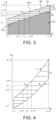
- the inner edge 16 of the preform layer 2 is shaped and dimensioned so that during the wrapping step the inner edge 16 is continuously coincident with the outer circumferential surface 26 of the mandrel 20, whereby as shown in Figure 3 the elongate tube 28 comprises a plurality of wrapped layers 34 forming a spiral 42 about the longitudinal axis L-L, wherein each wrapped layer 34 is constantly oriented with respect to a cylindrical coordinate system about the longitudinal axis L-L.
- a contact between at least a portion of the inner edge 16 and a region of the outer circumferential surface 26 of the mandrel 20 that is non-cylindrical forms a continuous inner helical line HL1, extending along a plurality (i.e. at least 2) of the wrapped layers 34, for example at least 10 wrapped layers 34, which is coincident with the outer circumferential surface 26 of the mandrel 20.
- the continuous inner helical line HL1 has a uniform pitch between successive helical rotations of the wrapped layers 34.
- the pitch between successive helical rotations of the wrapped layers may be variable and non-linear.
- At least a portion of the outer edge 18 forms a continuous outer helical line HL2 at the outer surface 30 of the elongate tube 28 which is equidistant from the continuous inner helical line HL1 along the plurality of wrapped layers 34 so that the elongate tube 28 has a constant thickness along at least the said part of the length of the elongate tube 28.
- the orientation of the fibrous reinforcement in the elongate tube 28 can be controlled by providing a starting orientation of the fibrous reinforcement in the starting configuration.
- the fibrous reinforcement comprises structural fibres, for example structural fibres that are comprised in a unidirectional (UD) fibrous ply, that during the locating step are aligned in parallel with the longitudinal axis L-L and during the wrapping step are maintained constantly oriented with respect to a cylindrical coordinate system about the longitudinal axis L-L.
- UD unidirectional
- the preform layer 2 is shaped and dimensioned so that when the preform layer 2 is wound around the mandrel 20 about the axis of rotation that coincides with the longitudinal axis L-L of the mandrel 20, and the preform layer 2 is continuously fed along the feeding path 32 which is perpendicular to the longitudinal axis L-L of the mandrel 20, each wrap rotation, apart from the first wrap rotation, of the preform layer 2 around the mandrel 20 at least partially covers, and for some wrap rotations may wholly cover, the immediately previous wrap rotation.
- the preform layer 2 may be shaped and dimensioned so that when the preform layer 2 is wound around the mandrel 20 about the axis of rotation that coincides with the longitudinal axis L-L of the mandrel 20, at least some of the wrap rotations, apart from the first wrap rotation, of the preform layer 2 around the mandrel 20 may be adjacent to or spaced from the immediately previous wrap rotation.
- One or more preform layers may be comprised of more than one preform part which are adjacent to, or spaced from, each other along the length of the mandrel.
- the plural preform parts may be wrapped sequentially or at least partly simultaneously.
- Plural preform parts may be comprised of the same or different preform compositions, for example the same or different fabrics and/or resins and/or orientations.
- a second preform layer (not shown) may be correspondingly wrapped over the first preform layer 2.
- the second preform layer may be wrapped in the same or opposite rotational direction as the first preform layer 2 and/or the second preform layer may be wrapped in the same or opposite translational direction as the first preform layer 2.
- Further preform layers may be wrapped over the second preform layer.
- a preferred embodiment for the manufacture of a sports article such as a golf club shaft is a two-ply or three-ply preform, with the shaft comprising a laminate of two two-ply or three-ply preforms to form a four-ply of six-ply multilaminar structure.
- a first ply may comprise parallel oriented UD fibres which, after the wrapping step as described above, are oriented substantially longitudinally along the shaft, and one or two adjacent second plies each comprise parallel oriented fibres which, after the wrapping step as described above, are oriented helically around the shaft, for example at an angle of from 30 to 45 degrees relative to the longitudinal axis of the shaft.
- a three-ply preform may provide fibres at 0, +45 and -45 degrees to the longitudinal axis of the shaft.
- the preform layer(s) are wrapped under tension so that the initial wrapping locates the preform layer(s) fully in contact with the underlying surface, for example the outer circumferential surface of the mandrel for the first or only preform layer.
- This wrapping arrangement has particular application when the surface of the preform has a degree of tack, for example as exhibited by typical thermosetting resin-containing prepregs at room temperature.
- the preform layer(s) may be wrapped without applying a tension to the preform layer(s), so that the initial wrapping is somewhat loose and locates the preform layer(s) only partly in contact with the underlying surface and/or not fully at the desired position in the final elongate tube.
- tension may be applied to the preform layer(s) to cause the preform layer(s) to be slid under tension into the desired position in the final elongate tube.
- the elongate tube 20 is moulded on the mandrel 20 to form an elongate tubular shaft 36 comprised of a fibre-reinforced resin matrix composite material 38 formed from the preform layer 2.
- the resin material is provided in contact with the fibrous reinforcement 6 of the preform layer 2, and during the moulding step the resin material forms a resin matrix which incorporates the fibrous reinforcement 6.
- the preform layer 2 may comprise a prepreg, in which case the wrapped preform layer(s) 2 may be subjected to elevated temperature, and optionally external pressure applied to the outer surface of the elongate tube 20, to form the moulded elongate tubular shaft 36.
- dry fibrous reinforcement 6 is wrapped around the mandrel 20, and thereafter, before or during the moulding step, the resin material is added so as to be provided in contact with the fibrous reinforcement 6 of the preform layer 6, for example by liquid resin infusion or by providing a coherent solid resin layer adjacent to the dry fibrous reinforcement which liquefies during the moulding process and impregnates the fibrous reinforcement 6. Accordingly, during the moulding step the resin material forms a resin matrix which incorporates the fibrous reinforcement 6.
- the elongate tubular shaft 36 may be separated from the mandrel 20 to form a hollow tube; alternatively, the mandrel 20, or a part thereof, may be retained within the central longitudinal cavity 40 of the elongate tubular shaft 36 to form a solid component. In either case, the elongate tubular shaft 36 may be further processed to form a desired product, for example a golf club shaft, a fishing rod or any other elongate tubular article that may usefully be composed of a fibre-reinforced resin matrix composite material.
- the inner edge 16 of the preform layer 2 is shaped and dimensioned so that during the wrapping step the inner edge 16 is continuously coincident with the outer circumferential surface 26 of the mandrel 20, whereby the elongate tube 28 comprises a plurality of wrapped layers 34 forming a spiral 42 about the longitudinal axis L-L, wherein each wrapped layer 34 is parallel to the longitudinal axis L-L, the shape and configuration of the preform layer 2 is predetermined based upon the geometry of the elongate tube, which can provide that each wrapped layer 34 is wrinkle-free and each region of the wrapped layer 34 is consistently aligned with the longitudinal axis L-L.
- This provides a high quality composite structure in which the fibre orientations and layer configurations in the moulded tubular product are highly accurately controlled and consistently achieved along the entire length of the elongate tubular shaft 36.
- the preform layer 2 is shaped and dimensioned so that when the preform layer 2 is in a planar configuration at least a portion of the inner edge 16 is defined using a rectangular coordinate system having x and y axes.
- the x axis is parallel to a spacing between the first and second end portions 12, 14, and parallel to the axis of rotation R-R, and thereby also parallel to the longitudinal axis L-L of the mandrel 20 about which the preform layer 2 is wrapped.
- the shape and dimensions of the inner edge 16, along its length relative to the longitudinal axis L-L are a function of both the preform layer 2, in particular the thickness of the preform layer 2, and the elongate tube 28 that is formed, in particular the number of rotations of the wrapped preform layer 34 and the circumference of wrapped preform layer 34, at any given position along the length of the inner edge 16 relative to the longitudinal axis L-L.
- this relationship can be determined for any given mandrel geometry by calculating the location of the inner edge 16 starting from a position at which the inner edge 16 adjoins the first end portion 12 of the preform layer 2, which is the part of the inner edge 16 which initially contacts the outer circumferential surface 26 of the mandrel 20 during the wrapping step.
- the shape and dimensions of the inner edge 16 are calculated for each successive wrapping rotation along the entire length of the inner edge 16.
- the outer edge 18 may comprise a linear edge parallel with the x axis, and thereby parallel with the longitudinal axis L-L of the mandrel 20.
- the wrapping Since the wrapping is perpendicular to the axis of rotation R-R, corresponding to the longitudinal axis L-L of the mandrel 20, the wrapping can be easily achieved and reliably controlled using a simple control system. This is because by geometrically matching the shape and configuration of the preform layer 2, including the thickness of the preform layer 2, to the shape and configuration of the mandrel 20 and the resultant elongate tube 28, such geometric matching can avoid complicated and problematic wrapping parameters.
- a preform tape is helically wound a mandrel at a winding angle that is at an acute angle to the longitudinal axis.
- the external diameter of the mandrel determines the internal diameter of the tube which is formed.
- the tape can easily become misaligned relative to the desired fibre orientations.
- the change in diameter of the mandrel and tube being formed causes a change in the angle of the tape relative to the mandrel surface. This can cause wrinkles in the wrapped layers and misaligned fibres, and requires complicated and careful control, by associated control systems, of the wrapping process to avoid such fibre misalignment.
- the present invention provides a reliable and consistent method of manufacturing composite material tubes having high quality fibre orientation and alignment which can be achieved using a low cost and simple manufacturing apparatus.
- the flexible preform layer 2 has a shape and dimensions which have been determined to enable the flexible preform layer 2 to be wrapped about a frusto-conical mandrel 20 to form an elongate tubular shaft 28 which is frusto-conical and has a constant wall thickness.
- Figure 2a is a plan view of the flexible preform layer 2 of Figure 1 shown relative to the x and y axes of a rectangular coordinate system.
- Figure 2b shows the flexible preform layer 2 after wrapping about the frusto-conical mandrel 20 to form the elongate tube 28, which is subsequently moulded to form the elongate tubular shaft 36, which is frusto-conical and has a constant wall thickness.
- the frusto-conical mandrel 20 has a circular cross-section.
- the wrapping step progressively wraps the flexible preform layer 2 on the mandrel 20 from the first end portion 12 to the second end portion 14.
- the horizontal lines H indicated on the preform layer 2 represent respective the beginning and end of successive wrap layers each time a wrapping revolution is completed. It can be seen that as the wrapping progresses from the first end portion 12 to the second end portion 14, the separation distance between the horizontal lines H progressively increases as a result of the increase in diameter of the outer surface 30 of the elongate tube 28 proceeding from the relatively small diameter end 37 to the relatively large diameter end 39 of the elongate tube 28, and a corresponding increase in circumference of each successive wrapped layer 34.
- the frustoconical surface 26 is inclined at an angle ⁇ to the longitudinal axis L-L of the mandrel 20.
- this formula may be readily modified to define the shape and dimensions of only a part of a preform layer 2, which part is intended to be wrapped over less than one revolution of the mandrel 20, for example by calculating a proportion of the circumference 2nr n .
- this figure illustrates the wrapping of the preform layer 2 around the mandrel 20 to form the elongate tube 28 comprised of plural wrapped layers 34.
- the mandrel 20 is frusto-conical with a constant angle of inclination ⁇ to the longitudinal axis of the mandrel 20.
- the preform layer 2 has a constant thickness
- the resultant elongate tube 28 has a constant wall thickness.
- Each horizontal line is defined by two points A and B that intersect respectively with the outer tube diameter and inner tube diameter with the following coordinates: A i x i A r i and B i x i B r i
- this figure illustrates the shape and dimensions of the preform layer 2 used to form the elongate tube 28 of Figure 3 when the preform layer is in a planar configuration relative to the rectangular coordinate system as described above.
- the y coordinate of the unwrapped planar preform layer 2, which applies to both the inner and outer edges 16, 18 at a given number of wrapped layers 34, is obtained by calculating the sum of all the circumferences of the perimeters of the previous wrapped layers 34.
- this formula may be readily modified to define the shape and dimensions of only a part of a preform layer 2, which part is intended to be wrapped over less than one revolution of the mandrel 20, for example by calculating a proportion of the circumference 2 ⁇ r n .
- the x coordinate of the outer edge 18 can be correspondingly calculated.
- the x, y coordinates of the preform layer 2 can therefore be defined as: A i x i A y i and B i x i B y i
- a typical thickness of the preform layer 2 is 0.17 mm and typically the elongate tube 28 has a constant thickness comprised of 15 wrapped layers 34, i.e. a typical tube thickness of about 2.5 mm.
- a typical tube thickness of about 2.5 mm may be used in accordance with the present invention.
- FIG 14 illustrates schematically a part of an elongate tubular shaft 300 comprised of a fibre-reinforced resin matrix composite material 302 in accordance with a further embodiment of the present invention.
- the shaft 300 comprises an elongate tubular body 304 comprising a stack 306 of wrapped layers 308.
- Each wrapped layer 308 comprises fibrous reinforcement 310 in a resin matrix 312.
- the wrapped layers 308 have such a small thickness, and the resin has flowed during the moulding process so as to be in contact with the entire outer circumferential surface of the mandrel and any outer mould part, so that in the moulded elongate tubular shaft 300 the helical edges of the layers would appear to the naked eye to be smoothly and continuously inclined at the outer and inner surfaces so as to be aligned with the overall frusto-conical shape of the elongate tubular shaft 300.
- the elongate tubular body 304 has an inner elongate circumferential surface 314, which has a first surface part 316 having a non-cylindrical geometry along at least a part of a length of the elongate tubular body 304.
- the non-cylindrical geometry is a frusto-conical shape.
- the elongate tubular body 304 also has an outer elongate circumferential surface 318, which in this embodiment, as also shown in Figure 3 , has a non-cylindrical geometry which is a frusto-conical shape.
- the stack 306 of wrapped layers 308 of fibrous reinforcement 310 comprises a fibrous layer 320.
- the fibrous layer 320 comprises at least one ply of the fibrous reinforcement 310.
- the fibrous reinforcement 310 comprises structural fibres that are constantly oriented with respect to a cylindrical coordinate system about the longitudinal axis L-L.
- the structural fibres are comprised in a unidirectional (UD) fibrous ply.
- the fibrous layer 320 is spirally wrapped about a longitudinal axis L-L of the elongate tubular body 304 to form the stack 306 of wrapped layers 308.
- Each wrapped layer 308 is parallel to the longitudinal axis L-L.
- the fibrous layer 320 has a non-constant width, as shown in Figure 3 , which varies non-linearly with a change in radius of the inner elongate circumferential surface 314 in the portion 322.
- the fibrous reinforcement 310 comprises fibres 324 that are, along the length of the elongate tubular body 304, constantly oriented with respect to a cylindrical coordinate system about the longitudinal axis L-L of the elongate tubular body 304.
- the fibre orientation in any said portion 322 is independent of the geometry of the inner and outer elongate circumferential surfaces 314, 318 of that portion 322.
- an inner edge 326 of the fibrous layer 320 is coincident with the inner circumferential surface 314 and forms a continuous inner helical line HL3, extending along a plurality of the wrapped layers 308.
- the continuous inner helical line HL3 has a uniform pitch between successive helical rotations of the wrapped layers 308.
- the continuous inner helical line HL3 typically extends along at least 10 of the wrapped layers 308.
- At least a portion 328 of the inner edge 326 is curved relative to a transverse plane T-T extending orthogonal to the longitudinal axis L-L.
- the curved portion 328 of the inner edge 326 is convexly curved with respect to the fibrous layer 320.
- the outer elongate circumferential surface 318 has a non-cylindrical geometry and the elongate tubular body 304 has a constant thickness along at least a part of the length thereof.
- the outer elongate circumferential surface may have a cylindrical geometry and/or the elongate tubular body may have a non-constant thickness along at least a part of the length thereof.
- Figure 5 illustrates a further embodiment of the present invention which is a modification of the embodiment of Figures 2a and 2b .
- Figure 5a is a plan view of the flexible preform layer 52 shown relative to the x and y axes of the rectangular coordinate system and
- Figure 5b shows the flexible preform layer 52 after wrapping about the frusto-conical mandrel 54 to form the elongate tube 56, which is subsequently moulded to form an elongate tubular shaft, which is frusto-conical and has a constant wall thickness.
- the only modification is that the preform layer 52 comprises a hole 58 extending through a thickness of the preform layer 52.
- the hole 58 is positioned inwardly of the first and second end portions 12, 14 and the inner and outer edges 16, 18.
- the hole 58 is circular but may have any other shape and dimensions.
- the flexible preform layer 52 can be wrapped to form the elongate tube 56 and provide an opening, depression or cavity in the elongate tube 56. In other embodiments, plural holes may be present.
- Figure 6 illustrates a further embodiment of the present invention which is a further modification of the embodiment of Figures 2a and 2b .
- Figure 6a is a plan view of the flexible preform layer 62 shown relative to the x and y axes of the rectangular coordinate system and
- Figure 6b shows the flexible preform layer 62 after wrapping about the frusto-conical mandrel 64 to form the elongate tube 66, which is subsequently moulded to form an elongate tubular shaft, which is frusto-conical and has a constant wall thickness.
- the only modification is that the preform layer 62 is comprised of first and second layer portions 68, 70 thereof.
- the first layer portion 68 is initially wrapped around the mandrel 64 as described above, and thereafter the second layer portion 70 is subsequently wrapped around the mandrel 64 as described above and at least partly over the first layer portion 68.
- Further layer portions may optionally be provided.
- first and second layer portions 68, 70 have the same thickness, and so a constant thickness elongate tube 66 is formed.
- first and second layer portions 68, 70 may have different thickness so that elongate tube 66 has first and second thickness regions, preferably with a transition region therebetween.
- first and second layer portions 68, 70 may have different fibre reinforcements, resins, orientations, etc.
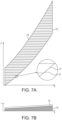
- Figure 7 illustrates a further embodiment of the present invention which is a further modification of the embodiment of Figures 2a and 2b .
- Figure 7a is a plan view of the flexible preform layer 72 shown relative to the x and y axes of the rectangular coordinate system and
- Figure 7b shows the flexible preform layer 72 after wrapping about the mandrel 74 to form the elongate tube 76, which is subsequently moulded to form an elongate tubular shaft, which has a constant wall thickness.
- the mandrel 74, and consequently the elongate tube 76 is not frusto-conical with a circular cross-section but instead is frusto-pyramidal with a square cross-section.
- the square profile of the elongate tube 76 can be incorporated into the calculation of an oscillating edge profile 77 on the inner and outer edges 75, 79 of the preform layer 72.
- the mandrel may have other non-circular cross-sections and may have any other regular (e.g. polygonal, elliptical) or non-regular shapes.
- Figure 8 illustrates a further embodiment of the present invention which is a further modification of the embodiment of Figures 2a and 2b .
- Figure 8a is a plan view of the flexible preform layer 82 shown relative to the x and y axes of the rectangular coordinate system and
- Figure 8b shows the flexible preform layer 82 after wrapping about the mandrel 84 to form the elongate tube 86, which is subsequently moulded to form an elongate tubular shaft, which has a constant wall thickness.
- the only modification is that the thickness of the preform layer 82 is increased, and consequently for a given thickness of the elongate tube 86 the number of wrapper layers is decreased.
- a typical thickness of the preform layer is 0.215 mm and typically the elongate tube has a constant thickness comprised of 8 wrapped layers, i.e. a typical tube thickness of about 1.7 mm.
- Figure 9 illustrates a further embodiment of the present invention which is a further modification of the embodiment of Figures 2a and 2b .
- Figure 9a is a plan view of the flexible preform layer 90 shown relative to the x and y axes of the rectangular coordinate system and
- Figure 9b shows the flexible preform layer 90 after wrapping about the mandrel 91 to form the elongate tube 92, which is subsequently moulded to form an elongate tubular shaft, which has a non-constant wall thickness.
- the preform layer 90 and mandrel 91 are shaped and dimensioned to form a cylindrical outer surface 93 of the elongate tube 92.
- the outer edge 94 is linear and parallel with the axis of rotation, instead of being concavely curved as in the embodiment of Figures 2 to 8 .
- the outer circumferential surface 95 of the mandrel 91 further comprises a cylindrical surface 96a, 96b adjacent to the frusto-conical surface 97 at at least one end 98a, 98b of the frusto-conical surface 97.
- the preform layer 90 is shaped and dimensioned so that when the preform layer 90 is in a planar configuration a respective second portion 99a, 99b of the inner edge 100, that in the wrapping step contacts the cylindrical surface 96a, 96b, is linear and parallel with the axis of rotation, and the longitudinal axis, in the wrapping step.
- Figure 10 illustrates a further embodiment of the present invention which is a further modification of the embodiment of Figures 2a and 2b .
- Figure 10a is a plan view of the flexible preform layer 102 shown relative to the x and y axes of the rectangular coordinate system and
- Figure 10b shows the flexible preform layer 102 after wrapping about the mandrel 103 to form the elongate tube 104, which is subsequently moulded to form an elongate tubular shaft, which has a non-constant wall thickness.
- the preform layer 102 and mandrel 103 are shaped and dimensioned to form first and second cylindrical outer surfaces 105a, 105b at opposite ends 106a, 106b of the elongate tube 104, and a conical outer surface 105c interconnects the first and second cylindrical outer surfaces 105a, 105b.
- the first and second cylindrical outer surfaces 105a, 105b are external to respective first and second cylindrical wall portions 101a, 101b.
- the first cylindrical wall portion 101a has a wall thickness that is greater than the wall thickness of the second cylindrical wall portion 101b.
- the conical outer surface 105c is external to a conical wall portion 101c that progressively increases in wall thickness from the first cylindrical wall portion 101a to the second cylindrical wall portion 101b.
- the preform layer 102 is shaped and dimensioned so that when the preform layer 102 is in a planar configuration a respective second portion 107a, 107b of the inner edge 108, that in the wrapping step contacts the cylindrical surfaces 109a, 109b of the mandrel 103, is linear and parallel with the axis of rotation, and the longitudinal axis in the wrapping step.
- the preform layer 102 is shaped and dimensioned so that the outer edge 110 comprises a central curved portion 112 between opposite linear portions 113a, 113b.
- Each respective opposite linear portion 113a, 113b of the outer edge 110, that in the wrapping step is remote from the cylindrical surfaces 109a, 109b of the mandrel 103, is linear and parallel with the axis of rotation, and the longitudinal axis in the wrapping step.
- Figure 11 illustrates a further embodiment of the present invention which is a further modification of the embodiment of Figures 2a and 2b .
- Figure 11a is a plan view of the flexible preform layer 115 shown relative to the x and y axes of the rectangular coordinate system and
- Figure 11b shows the flexible preform layer 115 after wrapping about the mandrel 116 to form the elongate tube 117, which is subsequently moulded to form an elongate tubular shaft, which has a non-constant wall thickness.
- the inner edge 118 of the preform layer 115 and the mandrel 116 are shaped and dimensioned the same as for the embodiment of Figures 2a and 2b to have a constant angle of inclination for a frusto-conical shape.
- the outer edge 119 of the preform layer 115 is shaped and dimensioned to form an outer surface 120 of the elongate tube 117 which has varying geometry and dimensions.
- the outer surface 120 has a first cylindrical portion 121, a first inclined portion 122 at a first inclination angle, a second inclined portion 123 at a second inclination angle, a third inclined portion 124 at a third inclination angle, a fourth inclined portion 125 at a fourth inclination angle, a second cylindrical portion 126 and a fifth inclined portion 127 at a fifth inclination angle.
- the outer edge 119 of the preform layer 115 is shaped and dimensioned to provide a first linear portion 131 to form the first cylindrical portion 121, a first curved portion 132 to form the first inclined portion 122, a second curved portion 133 to form the second inclined portion 123, a third curved portion 134 to form the third inclined portion 124, a fourth curved portion 135 to form the fourth inclined portion 125, a second linear portion 136 to form the second cylindrical portion 126 and a fifth curved portion 137 to form the fifth inclined portion 127.
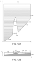
- Figure 12 illustrates a further embodiment of the present invention which is a further modification of the embodiment of Figures 2a and 2b .
- Figure 12a is a plan view of the flexible preform layer 140 shown relative to the x and y axes of the rectangular coordinate system and
- Figure 12b shows the flexible preform layer 140 after wrapping about the mandrel 142 to form the elongate tube 144, which is subsequently moulded to form an elongate tubular shaft, which has a non-constant wall thickness.
- the mandrel 142 is shaped and dimensioned the same as for the embodiment of Figures 2a and 2b to have a constant angle of inclination for a frusto-conical shape, except that the mandrel 142 incorporates an outward circumferential protrusion 148 having oppositely inclined frusto-conical faces 150, 152, having different inclination angles to the longitudinal axis of the mandrel 142, on opposite edges of a central inclined face 154.
- the inner edge 156 of the preform layer 140 has opposite lower and upper curved portions 158, 160 for wrapping around the lower and upper inclined portions 162, 164 of the mandrel 142 on opposite edges of the protrusion 148.
- the inner edge 156 further has an inwardly oriented notch 166 for wrapping around the protrusion 148.
- the notch 166 is defined by a first curved portion 168 to wrap around the lower frusto-conical face 150, a second curved portion 170 to wrap around the central inclined face 154, and a third curved portion 172 to wrap around the upper frusto-conical face 152.
- the outer edge 174 of the preform layer 140 is linear and parallel to the axis of rotation to form an outer surface 176 of the elongate tube 144 which is cylindrical, as in the embodiment of Figure 9 .
- Figure 13 illustrates a further embodiment of the present invention which is a further modification of the embodiment of Figure 12 .
- Figure 13a is a plan view of the flexible preform layer 180 shown relative to the x and y axes of the rectangular coordinate system and
- Figure 13b shows the flexible preform layer 180 after wrapping about the mandrel 182 to form the elongate tube 184, which is subsequently moulded to form an elongate tubular shaft, which has a non-constant wall thickness.
- the mandrel 182 is shaped and dimensioned the same as for the embodiment of Figure 12 to have a constant angle of inclination for a frusto-conical shape, except that the mandrel 182 incorporates an outward circumferential protrusion 186 which has a re-entrant groove 188.
- the protrusion 186 has oppositely inclined frusto-conical faces 190, 192, having different inclination angles to the longitudinal axis of the mandrel 182, on opposite sides of a central cylindrical face 194 and the groove 188 is defined by a re-entrant inclined face 196 which connects between the frusto-conical face 192 and the primary outer frusto-conical surface 198 of the frusto-conical shaped mandrel 182.
- the inner edge 200 of the preform layer 180 has opposite lower and upper curved portions 202, 204 for wrapping around the lower and upper inclined portions 206, 208 of the mandrel 182 on opposite sides of the protrusion 186.
- the inner edge 200 further has an inwardly oriented notch 210 for wrapping around the protrusion 186.
- the notch 210 is defined by a first curved portion 212 to wrap around the lower frusto-conical face 190, a first linear portion 214 to wrap around the central cylindrical face 194, a second curved portion 216 to wrap around the upper frusto-conical face 192, and a third curved portion 218 to fill in the groove 188 between the re-entrant inclined face 196 and the upper inclined portion 208 of the primary outer frusto-conical surface 198.
- the outer edge 220 of the preform layer 180 is linear and parallel to the axis of rotation to form an outer surface 222 of the elongate tube 184 which is cylindrical, as in the embodiment of Figure 12 .
- the mandrel may have any combination of circumferential shapes, dimensions and cross-sectional shapes.
- the number of preform layers wound around the mandrel may also be greater than one.
- the number of plies of the preform layer may be one or more than one and the orientation of the fibres of the plies relative to the direction of the preform layer that is parallel with the axis of rotation may be any angle suitable for providing a desired performance of the composite structure.
- a fibre-reinforced composite structure in a proportion (for example by weight) of unidirectional fibres having a direction along the axis of the tubular shaft, which are beneficial for the main performance of the composite structure, is greater than the proportion (for example by weight) of fibres, which may optionally be unidirectional fibres, obliquely orientated relative to that direction.
Landscapes
- Engineering & Computer Science (AREA)
- Mechanical Engineering (AREA)
- Chemical & Material Sciences (AREA)
- Composite Materials (AREA)
- Textile Engineering (AREA)
- General Engineering & Computer Science (AREA)
- Ocean & Marine Engineering (AREA)
- Health & Medical Sciences (AREA)
- General Health & Medical Sciences (AREA)
- Physical Education & Sports Medicine (AREA)
- Moulding By Coating Moulds (AREA)
Description
- The present invention relates to a method of manufacturing an elongate tubular shaft comprised of a fibre-reinforced resin matrix composite material. The present invention also relates to an elongate tubular shaft comprised of a fibre-reinforced resin matrix composite material.
- It is commonly known in the art of composite materials that a composite material tube, otherwise called a tubular shaft, may be produced by a method in which a tape of preform material is wound, for example helically wound, in a superposed manner around a metallic mandrel. Then in a moulding process pressure is applied with a compacting system on this composite structure, the thermoset and/or thermoplastic resin matrix is consolidated, and then the mandrel is removed from the moulded tubular product.
- Alternatively the preform material may be in the form of a sheet that is wound along a rotational axis having a direction aligned with respect to a longitudinal axis of the mandrel. In particular, such composite tubes are generally made by a roll wrapping process. The sheet may be oriented perpendicular, or at an inclined angle, to the longitudinal axis of the mandrel. Roll wrapping comprises wrapping around the mandrel individual preforms or individual layers of preform material having the same or different length as the tube and a width corresponding to a certain number of revolutions around the mandrel.
- The preform material may comprise a fibrous layer that consists of dry fibrous material, i.e. fibrous material which is free of a resin material, for example a thermoset and/or thermoplastic resin material, that is subsequently used to form the resin matrix of the composite material. After the fibrous layer has been wound as described above, the fibrous material may be coated by, impregnated by or infused by a resin material prior to or during the moulding step. Alternatively, the preform material may comprise a prepreg material. Such prepreg material is widely used in the manufacture of composite parts and structures. Prepreg material is a combination of thermoset and/or thermoplastic resin matrix and fibre reinforcement, in which the resin at least partially, typically completely, impregnates the fibre reinforcement.
- When winding a preform or prepreg, either helically using a narrow tape, or by roll wrapping a sheet aligned perpendicularly or at an inclination with respect to the mandrel, around a mandrel that has other than a cylindrical surface, i.e. a cylindrical surface provided by a circular cross-section of a given radius extending along the entire length of the mandrel, there can be significant technical problems.
- A first technical problem is that since the cross-section of the mandrel changes along the length of the mandrel, the prepreg can become skewed relative to the desired wrapping direction. This can cause wrinkles and fibre mis-alignment to be present in the wrapped elongate tube, which can seriously degrade the mechanical performance, and visual appearance, of the resultant elongate tubular shaft comprised of the fibre-reinforced resin matrix composite material formed from the prepreg.
- For high performance composite material products it is essential that the fibre orientation and alignment along the entire length of the tubular shaft is maintained within the desired close tolerances in order to achieve high mechanical properties.
- Fibre mis-alignment is a particular problem in the manufacture of non-cylindrical tubes, most particularly when product uniformity and consistency is a key performance parameter.
- Another problem in the manufacture of non-cylindrical tubes having complex tube geometry is that the fibre layers can be inadvertently bent, twisted or folded, leading to the undesired formation of wrinkles in the preform layers that are manifested as misaligned or bent fibres or even voids in the final moulded composite material product.
- Moreover, wrinkles and fibre mis-alignment can lead to a lack of consistency in performance between plural tubular products. Known manufacturing methods can encounter significant production problems in attaining such desired properties.
- A second technical problem is that to accommodate changes in the geometry of the mandrel along its length, this can require a high level of manual intervention during the manufacturing process, and consequently a low level of automation. This increases manufacturing cost and complexity, and reduces the consistency and uniformity of plural tubular products.
- A third technical problem is that such known processes can generate a high level of prepreg waste as a result of the prepreg tape or sheet having to be individually cut or tailored to remove excess material from the mandrel, or as a result of excess material having to be removed from the tubular product following the moulding step, or as a result of the manufactured tubular products being rejected by failing to meet the desired quality.
- Furthermore, it is known to manufacture sports articles such as golf club shafts, fishing rods, rackets, etc. from a fibre-reinforced resin matrix composite material, in particular a carbon fibre composite material. However, elongate tubular shafts of carbon fibre composite material tend to suffer from the problem of exhibiting non-uniform properties, in particular a non-uniform wall thickness which leads to undesired variations in flexural stiffness along the shaft, in particular when the flexural force is applied in different rotational orientations around the axis of the shaft. Tubular sports articles often need to incorporate controlled variable thickness in order locally to control the stiffness of the article; however, it is difficult to automate a manufacturing process reliably and repeatably to manufacture such controlled variable thickness with a high degree of uniformity and consistency for multiple products.
-
GB-A-2177062 -
US-A-2011/0097526 discloses a woven fiber preform for forming a fiber reinforced composite incorporating the preform. The woven preform includes a plurality of warp and weft yarns or fibers interwoven to form a continuous spiral fabric. The spiral fabric may take the shape of an Archimedes spiral. The weft yarns in the preform may have a uniform or variable pick spacing, or a uniform or variable angular separation. The spiral fabric of the Archimedes spiral may be assembled or wrapped to form a conical shell structure, which could be a portion of a spinner or an exit cone. This disclosure suffers from a problem that the preform has a complex specific spiral geometry and can only be used to make a specific geometric structure of a conical shell. Moreover, if the weft yarns have uniform spacing and uniform angular separation, then in the conical shell the yarns become misaligned; however, if the weft yarns have variable spacing and/or variable angular separation, then although in the conical shell the yarns can be aligned conically the preform is very complicated to weave with a variable fibre structure, and each preform can only be used to make a specific geometric shape. There is no disclosure how in practice to make such a very complicated fabric for the preform. Furthermore, there is no disclosure how accurately to manufacture a complex shape other than a geometric conical shell. -
US-A-2003/0056846 discloses a length of fabric with a variable width to form a tube of variable diameter. This disclosure suffers from a problem that the individual tube has a specific arrangement of the warp and weft fibres that can only be used to make a specific geometric structure of a variable diameter tube. The fabric is very complicated to weave with a variable fibre structure. There is no disclosure how to control the outer geometry of the tube. -
WO-A-2004/067264 discloses a method of depositing inclined fibrous layers from a continuous wound band onto a support that may have variable diameter. This disclosure suffers from a problem that the method is very complex. Furthermore, there is no disclosure how accurately to manufacture a complex shape other than cylindrical or frustoconical tubular shapes from the inclined fibrous layers. There is no disclosure how to provide fibres oriented in the longitudinal direction along a substantial length, or in particular along the entire length, of the tube. -
US-A-5876322 discloses that composite fibers are woven into helical fabric strips which wind upon one another as a helix to form a cylinder. When the helical strips are impregnated with resin, heated to the thermoset temperature of the resin, and compressed and cured, a cylindrical composite body results having the individual fibers of the body only arrayed radially or circumferentially. - The aim of the present invention is therefore at least partially to overcome one or more of the above-described problems encountered by known methods for the manufacture of composite material tubular shafts.
- The present invention accordingly aims to provide an improved manufacturing method for an elongate tubular shaft comprised of a fibre-reinforced resin matrix composite material, in particular in which the elongate tubular shaft can exhibit high quality mechanical properties even though the shaft may have a non-uniform thickness, cross-section and/or external or internal shape and dimensions along the length of the shaft.
- Most particularly, present invention aims to provide an improved manufacturing method for an elongate tubular shaft comprised of a fibre-reinforced resin matrix composite material, which can be automated in order reliably, consistently and repeatably to provide, in a low cost production method, a tubular shaft having a highly concentric wall structure, with a uniformly controlled wall thickness around the axis of the shaft and accurate control of fibre alignment around the axis of the shaft, which in turn can provide that the shaft exhibits constant flexural properties around the axis of the shaft.
- The present invention further aims to provide an improved manufacturing method for an elongate tubular shaft comprised of a fibre-reinforced resin matrix composite material which can increase the design possibilities of the ultimate tubular product by enabling complex tube geometries to be consistently manufactured, preferably by using an automated or automatable manufacturing method.
- Finally, the present invention also aims to provide an improved elongate tubular shaft comprised of a fibre-reinforced resin matrix composite material which has a non-cylindrical internal circumferential surface and cross-section. In particular, the present invention also aims to provide an improved elongate tubular shaft comprised of a fibre-reinforced resin matrix composite material yet which can exhibit highly accurate and consistent fibre alignment around the axis of the shaft, which in turn can provide high quality mechanical properties along the length of the shaft, even in the case that the shaft incorporates complex tube geometries.
- The present invention provides a method of manufacturing an elongate tubular shaft comprised of a fibre-reinforced resin matrix composite material according to
claim 1. The method of the preferred embodiments of the present invention provides that each fibre is constantly oriented with respect to a cylindrical coordinate system about the axis of rotation of the mandrel. - Preferred features of the method are defined in
dependent claims 2 to 8. - The present invention also provides an elongate tubular shaft comprised of a fibre-reinforced resin matrix composite material according to claim 9.
- Preferred features of the elongate tubular shaft are defined in
dependent claims 10 to 15. - The preferred embodiments of the present invention can provide a method of manufacturing an elongate tubular shaft on a mandrel in which the cross-section of the mandrel changes along the length of the mandrel, and thereby has a "complex" shape.
- Despite such a complex mandrel shape, the orientation of the fibres can remain constant within a cylindrical coordinate system associated with the axis of rotation of the mandrel, even when using "long" fibres having a length of at least 50 mm, and the "long" fibres may have a length of more than 10 metres, at least some of which fibres may individually extend along the entire length of the elongate tubular shaft.
- This technical effect and advantage to achieve highly consistently accurate fibre orientation and alignment of such long fibres in an elongate tubular shaft formed from one or more wrapped preform layers is believed by the present inventors to be unique in the composite material art, and allows to increase the performance of fibre-reinforced composite structures for applications where product consistency is a key design and performance factor. Furthermore, by providing highly aligned "long" fibres having a length of at least 50 mm, or even a length of more than 10 metres, the mechanical properties, in particular the strength and toughness, of the composite material are increased.
- The inside tube geometry can have a complex shape, and can incorporate one or any combination of the following geometric or structural features: cone with increasing or/and decreasing or/and neutral slope; one or multiple bumps or protrusions; one or multiple ledges; one or multiple re-entrant grooves; or one or multiple depressions; a section of any shape and that can also vary along the length of the tube. Correspondingly, the outside tube geometry can have a complex shape, and can incorporate one or any combination of the following geometric or structural features: cone with increasing or/and decreasing or/and neutral slope; one or multiple bumps or protrusions; one or multiple ledges; one or multiple re-entrant grooves; or one or multiple depressions.
- The preferred embodiments of the present invention can provide a method of manufacturing an elongate tubular shaft on a mandrel in which the shaft has a complex tube geometry and can be moulded to a near net shape, and this can be achieved in one wrapping and moulding operation with very little waste and in a fully automated way, thus improving productivity and repeatability while reducing waste.
- Furthermore, the preferred embodiments of the present invention can provide a method of manufacturing an elongate tubular shaft on a mandrel in which there is an ability to control independently the inside tube and outside tube geometry, which increases the design space in a general way for the manufacture of tubular shafts.
- The preferred embodiments of the present invention can provide a method of manufacturing an elongate tubular shaft in which even though the cross-section of the mandrel changes along the length of the mandrel, the preform does not become skewed relative to the desired wrapping direction. Accordingly, wrinkles and fibre mis-alignment can be avoided or minimized in the wrapped elongate tube. The resultant elongate tubular shaft comprised of the fibre-reinforced resin matrix composite material can reliably, and consistently and repeatably, exhibit a high quality mechanical performance, and visual appearance. The fibre orientation and alignment along the entire length of the tubular shaft can be maintained within the desired close tolerances in order to achieve high mechanical properties.
- The preferred embodiments of the present invention can also provide a high level of automation, and a low level of, or no, manual intervention during the manufacturing process which accommodates changes in the geometry of the mandrel along its length, particularly when manufacturing tubes having a complex geometry. The manufacturing cost and complexity is reduced, and the uniformity of plural tubular products is increased, and the manufacturing time can be decreased, as compared to known manufacturing methods, particularly when manufacturing tubes having a complex geometry.
- The preferred embodiments of the present invention can also avoid or minimize preform waste depending on the complexity of the geometry of the elongate tubular shaft. In the preferred embodiments of the present invention, the shape and configuration of the or each preform layer to be wrapped around the mandrel is pre-calculated prior to the wrapping step, based on parameters of the combination of the thickness of the preform layer, the mandrel geometry and the tube geometry, to provide a complex preform geometry that is adapted to be wrapped perpendicularly around a complex mandrel geometry to form a complex tube geometry. By pre-calculating such a complex preform shape prior to the wrapping step, the wrapping can be automated and waste minimized, because the preform layer is cut and subsequently wrapped and then moulded to a "near net shape" which obviates or minimizes waste generation during or after the wrapping and moulding steps. The wrapping to form a preform tube near to the final product shape can consequently reduce waste, and also reduce or avoid any time required by a finishing process for finishing the final moulded tubular shaft, for example a grinding process.
- In summary, the preferred embodiments of the present invention can also provide a highly flexible automated manufacturing method for making complex tubular shafts composed of composite material. Consequently, the preferred embodiments of the present invention further provide a tubular shaft composed of composite material which can have on the one hand a complex geometry but one the other hand highly consistently and accurately aligned fibres, with associated high mechanical properties.
- The tubular shafts produced by the preferred embodiments of the present invention can be used to manufacture sports articles such as golf club shafts, fishing rods, rackets, masts for boats and windsurfing boards, etc., or any other high quality composite material tubular products, from a fibre-reinforced resin matrix composite material, in particular a glass or carbon fibre composite material.
- Other features and advantages of the present invention will appear more clearly from the detailed description of several non-limiting embodiments of the invention which are illustrated by the attached drawings in which:
-
Figure 1 is a schematic plan view of a preform layer that is suitable for use in a method of manufacturing an elongate tubular shaft comprised of a fibre-reinforced resin matrix composite material in accordance with an embodiment of the present invention; -
Figures 2a and 2b illustrate schematically, respectively, a plan view of a preform layer relative to a rectangular coordinate system, and a cross-section through the preform layer after wrapping around the mandrel in accordance with an embodiment of the present invention; -
Figure 3 is a graph illustrating in detail a cross-section through the layer structure of a wrapped preform layer on the mandrel in accordance with an embodiment of the present invention; -
Figure 4 is a graph illustrating in detail a plan of the preform layer used inFigure 3 indicating a calculation of the preform shape and dimensions to be wrapped onto the mandrel in accordance with an embodiment of the present invention; -
Figures 5a and 5b illustrate schematically, respectively, a plan view of a preform layer relative to a rectangular coordinate system, and a cross-section through the preform layer after wrapping around the mandrel in accordance with a second embodiment of the present invention; -
Figures 6a and 6b illustrate schematically, respectively, a plan view of a preform layer relative to a rectangular coordinate system, and a cross-section through the preform layer after wrapping around the mandrel in accordance with a third embodiment of the present invention; -
Figures 7a and 7b illustrate schematically, respectively, a plan view of a preform layer relative to a rectangular coordinate system, and a cross-section through the preform layer after wrapping around the mandrel in accordance with a fourth embodiment of the present invention; -
Figures 8a and 8b illustrate schematically, respectively, a plan view of a preform layer relative to a rectangular coordinate system, and a cross-section through the preform layer after wrapping around the mandrel in accordance with a fifth embodiment of the present invention; -
Figures 9a and 9b illustrate schematically, respectively, a plan view of a preform layer relative to a rectangular coordinate system, and a cross-section through the preform layer after wrapping around the mandrel in accordance with a sixth embodiment of the present invention; -
Figures 10a and 10b illustrate schematically, respectively, a plan view of a preform layer relative to a rectangular coordinate system, and a cross-section through the preform layer after wrapping around the mandrel in accordance with a seventh embodiment of the present invention; -
Figures 11a and 11b illustrate schematically, respectively, a plan view of a preform layer relative to a rectangular coordinate system, and a cross-section through the preform layer after wrapping around the mandrel in accordance with an eighth embodiment of the present invention; -
Figures 12a and 12b illustrate schematically, respectively, a plan view of a preform layer relative to a rectangular coordinate system, and a cross-section through the preform layer after wrapping around the mandrel in accordance with a ninth embodiment of the present invention; -
Figures 13a and 13b illustrate schematically, respectively, a plan view of a preform layer relative to a rectangular coordinate system, and a cross-section through the preform layer after wrapping around the mandrel in accordance with a tenth embodiment of the present invention; and -
Figure 14 illustrates schematically a longitudinal cross-sectional view though a part of an elongate tubular shaft comprised of a fibre-reinforced resin matrix composite material in accordance with a further embodiment of the present invention. -
Figures 1 andFigure 2a and 2b illustrate an example of aflexible preform layer 2 suitable for use in a method of manufacturing an elongate tubular shaft according to an embodiment of the present invention. Thepreform layer 2 is flexible which, in this specification, means that, as described hereinafter, thepreform layer 2 can be wound rotationally around a mandrel to form a desired tubular shape. Theflexible preform layer 2 comprises at least oneply 4 of fibrous reinforcement 6. Thepreform layer 2 has a frontmajor surface 10. Preferably, thepreform layer 2 has a constant thickness. However, in other embodiments the thickness may vary, optionally in a controlled manner, for example the thickness may vary linearly along the length of thepreform layer 2. The thickness of thepreform layer 2 is preferably within the range of from 0.015 to 5 mm, optionally from 0.1 to 2 mm. - The
preform layer 2 has first andsecond end portions outer edges outer edges first end portion 12 towards thesecond end portion 14. - In accordance with the present invention, when the
preform layer 2 is in a planar configuration, as shown inFigure 1 , at least theinner edge 16 is non-linear and a spacing between the inner andouter edges preform layer 2 extending between the first andsecond end portions - Accordingly, there is a non-linear relationship between the geometrical shape and dimensions of the
inner edge 16 of thepreform layer 2 and the length of thepreform layer 2 between the first andsecond end portions outer edges preform layer 2 between the first andsecond end portions preform layer 2 is wrapped around a non-cylindrical mandrel as described below, there is a non-linear relationship between on the one hand the position of theinner edge 16, and the spacing between the inner andouter edges preform layer 2 along a length direction of the mandrel and the cumulative number of rotations of thepreform layer 2 in a direction extending along the length direction of the mandrel, in particular along a longitudinal axis of the mandrel. - In the embodiment of
Figure 1 , the first andsecond end portions outer edges inner edge 16 is convexly curved and theouter edge 18 is concavely curved. Consequently, in this embodiment thepreform layer 2 is shaped and dimensioned so that when thepreform layer 2 is in a planar configuration at least a portion of theinner edge 16 is curved, preferably convexly curved. However, in other embodiments theinner edge 16 and theouter edge 18 may have different geometries, for example theinner edge 16 may be concavely curved and/or theouter edge 18 may be convexly curved. - As is described hereinafter, the curvatures of the inner and
outer edges outer edges outer edges flexible preform layer 2 is to be wrapped to form the elongate tubular shaft, the thickness of thepreform layer 2, and the shape and dimensions of the elongate tubular shaft. - The fibrous reinforcement 6 may have any fibre configuration, and may comprise woven fibres or non-woven fibres, for example in the form of unidirectional (UD) fibres, spread tow fibres, stitched fabrics, knitted or braided fabrics. The fibrous reinforcement 6 may comprises multiple fibres with the same or different orientations. The fibrous reinforcement 6 may comprise a single ply of fibres, or alternatively may comprise a stack of plural plies of fibres, the plies having the same or different fibre configurations.
- When plural plies are present, although the
entire preform layer 2 has a shape and dimensions defining the frontmajor surface 10, the first andsecond end portions outer edges preform layer 2, or one or more plies in the ply inpreform layer 2, may include at least one hole therein, the hole or holes being surrounded by thepreform layer 2. - The fibres of the fibrous reinforcement 6 may comprise any natural and/or synthetic fibres. Typically, the fibrous reinforcement 6 comprises glass, carbon, and/or aramid fibres, or cotton or jute fibres.
- The
preform layer 2 may comprise dry fibrous reinforcement 6, i.e. fibrous material which is free of a resin material, for example a thermoset and/or thermoplastic resin material, that is subsequently used to form the resin matrix of the composite material. After thepreform layer 2 has been wound as described below, the dry fibrous reinforcement 6 may be coated by, impregnated by or infused by a resin material prior to or during the moulding step. For example, a liquid resin may be infused into the dry fibrous reinforcement 6 prior to or during the moulding step. In another embodiment, a coherent solid resin layer may be deposited adjacent to the dry fibrous reinforcement 6 prior to or during the moulding step. Other techniques to combine fibre and resin to form the fibre-reinforced resin matrix composite material will be apparent to those skilled in the art. - Alternatively, the
preform layer 2 may comprise a prepreg material which is at least partly, optionally fully, impregnated by a resin. - The
resin 8 may be a thermoplastic or thermosetting resin. Any thermoplastic or thermosetting resin known to be suitable for use in manufacturing fibrous preforms may be used. Typically, a thermosetting resin such as an epoxy resin is used in conjunction with glass and/or carbon fibres in the fibrous reinforcement 6. When a thermosetting resin is used, thepreform layer 2 may comprise a prepreg, in which the fibrous reinforcement 6 is fully impregnated by the resin. In some embodiments, a single preform layer may be provided with different areas incorporating different resins, which may comprise a mixture of thermoplastic and/or thermosetting resins. - In alternative embodiments of the present invention, the
preform layer 2 may comprise a dry fibrous reinforcement layer and a resin layer, composed of a thermosetting resin or a thermoplastic resin, and the preform layer and the resin layer are stacked upon each other. In further embodiments of the present invention, the resin in thepreform layer 2, which is composed of a thermosetting resin or a thermoplastic resin, may be partially or totally precured before the subsequent wrapping step as described below. In other embodiments of the present invention, thepreform layer 2 may comprise a core material (not shown) and/or an adhesive material (not shown) on an upper surface of thepreform layer 2 or the fibrous reinforcement 6. The core material may comprises a layer of a cellular material, for example a cellular foam, typically composed of a polymer such as a polyolefin or a polyester, or a honeycomb material. When a core material is provided, the core material is sandwiched between opposed layers of fibrous reinforcement after the wrapping step and in the final elongate tubular shaft manufactured according to the present invention. - In the method of the present invention, as is also shown in
Figure 1 , anelongate mandrel 20 is provided. Themandrel 20 may be composed of a single part or multiple parts connected or assembled together. Themandrel 20 is typically composed of a metal, such as steel, but may alternatively be composed of a composite material, such as a fibre-reinforced resin matrix composite material. - The
mandrel 20 has a longitudinal axis L-L, and opposite first and second ends 22, 24 which are mutually spaced along the longitudinal axis L-L. Themandrel 20 has an outercircumferential surface 26 that is non-cylindrical along at least a part of a length of themandrel 20 extending along the longitudinal axis L-L. In the embodiment ofFigure 1 , the outercircumferential surface 26 that is non-cylindrical is frusto-conical. However, as described hereinafter, themandrel 20 may have any desired cross-sectional shape and dimensions, and additionally the cross-sectional shape and dimensions may vary along the length of the mandrel. The mandrelouter surface 26 can have a complex shape, and can incorporate one or any combination of the following geometric or structural features: cone with increasing or/and decreasing or/and neutral slope; one or multiple bumps or protrusions; one or multiple ledges; one or multiple re-entrant grooves; or one or multiple depressions; a section of any shape and that can also vary along the length of themandrel 20. - The present invention pre-shapes the preform layer in accordance with the shape and dimensions of the mandrel, and of the final elongate tube, so that after wrapping the preform layer about the mandrel by rotation around the longitudinal axis of the mandrel, the desired elongate tube is produced irrespective of the specific individual geometry of the mandrel. Accordingly, such pre-shaping of the preform layer allows a wide variety of different mandrel geometries to be used and a similar wide variety of elongate tube geometries to be produced.
- As described below with reference to various embodiments of the present invention, the first and
second end portions outer edges preform layer 2 may be provided with a variety of different shapes and dimensions to enable thepreform layer 2 to be wrapped about a variety of different mandrel shapes and dimensions to manufacture elongate tubes of a variety of different shapes and dimensions. The common feature in these embodiments is that the preform layer, in particular at least the inner edge of the preform layer which contacts the outer circumferential surface of the mandrel during wrapping, is pre-shaped to control the wrapping relative to the individual mandrel. - In order to manufacture the elongate tubular shaft, the
first end portion 12 of thepreform layer 2 is located adjacent to thefirst end 22 of themandrel 20 in a starting configuration. In the starting configuration, theinner edge 16 is oriented towards themandrel 20 and theouter edge 18 is oriented away from themandrel 20. - Then the
preform layer 2 is wrapped about themandrel 2 so that the outercircumferential surface 26 of themandrel 20 is progressively covered by the wrappedpreform layer 2 to form anelongate tube 28. - During this wrapping step, the
mandrel 20 and thepreform layer 2 are relatively rotated about an axis of rotation R-R that is along the longitudinal axis L-L of themandrel 20. Typically, themandrel 20 is rotated about the axis of rotation R-R to wrap thepreform layer 2 about themandrel 20, and thepreform layer 2 is rotationally static. Alternatively themandrel 20 is rotationally static and thepreform layer 2 is rotated about the axis of rotation R-R to wrap thepreform layer 2 about themandrel 20. - Also during this wrapping step, the
preform layer 2 is continuously fed, from thefirst end portion 12 to thesecond end portion 14 of thepreform layer 2, onto themandrel 20 along a feedingpath 32 which is perpendicular to the longitudinal axis L-L of themandrel 20 and thereby also perpendicular to the axis of rotation R-R. - The front
major surface 10 is rotationally wrapped into surface contact with the outercircumferential surface 26. After the first wrap rotation, the frontmajor surface 10 preferably at least partially overlaps with previously wrapped part of thepreform layer 2 on themandrel 20. As a result of the wrapping step, in theelongate tube 28 theinner edge 16 contacts the outercircumferential surface 26 of themandrel 20 and theouter edge 18 is located at an outercircumferential surface 30 of theelongate tube 28. - In particular, the
inner edge 16 of thepreform layer 2 is shaped and dimensioned so that during the wrapping step theinner edge 16 is continuously coincident with the outercircumferential surface 26 of themandrel 20, whereby as shown inFigure 3 theelongate tube 28 comprises a plurality of wrappedlayers 34 forming a spiral 42 about the longitudinal axis L-L, wherein each wrappedlayer 34 is constantly oriented with respect to a cylindrical coordinate system about the longitudinal axis L-L. - Preferably, during the wrapping step, along at least a part of the length of the
elongate tube 28 at aninner surface 29 thereof a contact between at least a portion of theinner edge 16 and a region of the outercircumferential surface 26 of themandrel 20 that is non-cylindrical forms a continuous inner helical line HL1, extending along a plurality (i.e. at least 2) of the wrapped layers 34, for example at least 10 wrappedlayers 34, which is coincident with the outercircumferential surface 26 of themandrel 20. - As a result of the combination of the specific geometry of the curved
inner edge 16 and the regular frusto-conicalcircumferential surface 26 of themandrel 20 having a constant angle of inclination to the longitudinal axis L-L, the continuous inner helical line HL1 has a uniform pitch between successive helical rotations of the wrapped layers 34. However, in other embodiments, for example having a non-regular non-cylindrical surface of the mandrel as described below, the pitch between successive helical rotations of the wrapped layers may be variable and non-linear. - In one embodiment, at least a portion of the
outer edge 18 forms a continuous outer helical line HL2 at theouter surface 30 of theelongate tube 28 which is equidistant from the continuous inner helical line HL1 along the plurality of wrappedlayers 34 so that theelongate tube 28 has a constant thickness along at least the said part of the length of theelongate tube 28. - Since the
preform layer 2 is located on the mandrel in a particular orientation and wrapped about the longitudinal axis L-L of themandrel 20, which thereby is also the longitudinal axis of theelongate tube 28, the orientation of the fibrous reinforcement in theelongate tube 28 can be controlled by providing a starting orientation of the fibrous reinforcement in the starting configuration. - In one typical embodiment, the fibrous reinforcement comprises structural fibres, for example structural fibres that are comprised in a unidirectional (UD) fibrous ply, that during the locating step are aligned in parallel with the longitudinal axis L-L and during the wrapping step are maintained constantly oriented with respect to a cylindrical coordinate system about the longitudinal axis L-L.
- In the preferred embodiments of the present invention, the
preform layer 2 is shaped and dimensioned so that when thepreform layer 2 is wound around themandrel 20 about the axis of rotation that coincides with the longitudinal axis L-L of themandrel 20, and thepreform layer 2 is continuously fed along the feedingpath 32 which is perpendicular to the longitudinal axis L-L of themandrel 20, each wrap rotation, apart from the first wrap rotation, of thepreform layer 2 around themandrel 20 at least partially covers, and for some wrap rotations may wholly cover, the immediately previous wrap rotation. - However, in some embodiments of the present invention the
preform layer 2 may be shaped and dimensioned so that when thepreform layer 2 is wound around themandrel 20 about the axis of rotation that coincides with the longitudinal axis L-L of themandrel 20, at least some of the wrap rotations, apart from the first wrap rotation, of thepreform layer 2 around themandrel 20 may be adjacent to or spaced from the immediately previous wrap rotation. - One or more preform layers may be comprised of more than one preform part which are adjacent to, or spaced from, each other along the length of the mandrel. The plural preform parts may be wrapped sequentially or at least partly simultaneously. Plural preform parts may be comprised of the same or different preform compositions, for example the same or different fabrics and/or resins and/or orientations.
- After the
preform layer 2 has been fully wrapped on themandrel 20, in some preferred embodiments of the present invention a second preform layer (not shown) may be correspondingly wrapped over thefirst preform layer 2. Optionally, the second preform layer may be wrapped in the same or opposite rotational direction as thefirst preform layer 2 and/or the second preform layer may be wrapped in the same or opposite translational direction as thefirst preform layer 2. Further preform layers may be wrapped over the second preform layer. These embodiments provide multi-layer tubular structures which, in the finished composite material product, may exhibit increased mechanical properties as compared to a single-layer tubular structure. - For example, a preferred embodiment for the manufacture of a sports article such as a golf club shaft is a two-ply or three-ply preform, with the shaft comprising a laminate of two two-ply or three-ply preforms to form a four-ply of six-ply multilaminar structure. In each two-ply or three-ply preform, a first ply may comprise parallel oriented UD fibres which, after the wrapping step as described above, are oriented substantially longitudinally along the shaft, and one or two adjacent second plies each comprise parallel oriented fibres which, after the wrapping step as described above, are oriented helically around the shaft, for example at an angle of from 30 to 45 degrees relative to the longitudinal axis of the shaft. For example, a three-ply preform may provide fibres at 0, +45 and -45 degrees to the longitudinal axis of the shaft.
- During the wrapping step, typically the preform layer(s) are wrapped under tension so that the initial wrapping locates the preform layer(s) fully in contact with the underlying surface, for example the outer circumferential surface of the mandrel for the first or only preform layer. This wrapping arrangement has particular application when the surface of the preform has a degree of tack, for example as exhibited by typical thermosetting resin-containing prepregs at room temperature. However, in alternative embodiments, particularly when the surface of the preform is tack-free, for example as exhibited by typical dry fibrous reinforcement, during the wrapping step the preform layer(s) may be wrapped without applying a tension to the preform layer(s), so that the initial wrapping is somewhat loose and locates the preform layer(s) only partly in contact with the underlying surface and/or not fully at the desired position in the final elongate tube. In such embodiments, after the wrapping step tension may be applied to the preform layer(s) to cause the preform layer(s) to be slid under tension into the desired position in the final elongate tube.
- Thereafter, the
elongate tube 20 is moulded on themandrel 20 to form an elongatetubular shaft 36 comprised of a fibre-reinforced resinmatrix composite material 38 formed from thepreform layer 2. Before or during the moulding step, the resin material is provided in contact with the fibrous reinforcement 6 of thepreform layer 2, and during the moulding step the resin material forms a resin matrix which incorporates the fibrous reinforcement 6. - As described above, in some embodiments the
preform layer 2 may comprise a prepreg, in which case the wrapped preform layer(s) 2 may be subjected to elevated temperature, and optionally external pressure applied to the outer surface of theelongate tube 20, to form the moulded elongatetubular shaft 36. - In other embodiments, dry fibrous reinforcement 6 is wrapped around the
mandrel 20, and thereafter, before or during the moulding step, the resin material is added so as to be provided in contact with the fibrous reinforcement 6 of the preform layer 6, for example by liquid resin infusion or by providing a coherent solid resin layer adjacent to the dry fibrous reinforcement which liquefies during the moulding process and impregnates the fibrous reinforcement 6. Accordingly, during the moulding step the resin material forms a resin matrix which incorporates the fibrous reinforcement 6. - After the moulding step, the elongate
tubular shaft 36 may be separated from themandrel 20 to form a hollow tube; alternatively, themandrel 20, or a part thereof, may be retained within the centrallongitudinal cavity 40 of the elongatetubular shaft 36 to form a solid component. In either case, the elongatetubular shaft 36 may be further processed to form a desired product, for example a golf club shaft, a fishing rod or any other elongate tubular article that may usefully be composed of a fibre-reinforced resin matrix composite material. - By providing that the
inner edge 16 of thepreform layer 2 is shaped and dimensioned so that during the wrapping step theinner edge 16 is continuously coincident with the outercircumferential surface 26 of themandrel 20, whereby theelongate tube 28 comprises a plurality of wrappedlayers 34 forming a spiral 42 about the longitudinal axis L-L, wherein each wrappedlayer 34 is parallel to the longitudinal axis L-L, the shape and configuration of thepreform layer 2 is predetermined based upon the geometry of the elongate tube, which can provide that each wrappedlayer 34 is wrinkle-free and each region of the wrappedlayer 34 is consistently aligned with the longitudinal axis L-L. - This provides a high quality composite structure in which the fibre orientations and layer configurations in the moulded tubular product are highly accurately controlled and consistently achieved along the entire length of the elongate
tubular shaft 36. - In accordance with the preferred embodiments of the present invention, the
preform layer 2 is shaped and dimensioned so that when thepreform layer 2 is in a planar configuration at least a portion of theinner edge 16 is defined using a rectangular coordinate system having x and y axes. The x axis is parallel to a spacing between the first andsecond end portions mandrel 20 about which thepreform layer 2 is wrapped. The y axis is parallel to a spacing between the inner andouter edges inner edge 16 is defined by the relationship:
- B is the position of the inner edge relative to the rectangular coordinate system;
- n = the number of rotations of the wrapped preform layer;


- In other words, the shape and dimensions of the
inner edge 16, along its length relative to the longitudinal axis L-L, are a function of both thepreform layer 2, in particular the thickness of thepreform layer 2, and theelongate tube 28 that is formed, in particular the number of rotations of the wrappedpreform layer 34 and the circumference of wrappedpreform layer 34, at any given position along the length of theinner edge 16 relative to the longitudinal axis L-L. - In practice, this relationship can be determined for any given mandrel geometry by calculating the location of the
inner edge 16 starting from a position at which theinner edge 16 adjoins thefirst end portion 12 of thepreform layer 2, which is the part of theinner edge 16 which initially contacts the outercircumferential surface 26 of themandrel 20 during the wrapping step. - From that starting position, a calculation is made of the desired location of the
inner edge 16 on the outercircumferential surface 26 of themandrel 20 after one wrapping rotation, and this calculation is a function of the difference in circumference of themandrel 20 at zero wrapping and after one wrapping rotation, and the rate of change of that difference in circumference. For the second wrapping rotation a calculation is made of the desired location of theinner edge 16 on the outercircumferential surface 26 of themandrel 20 after the second wrapping rotation, and this calculation is a function of the difference in circumference of themandrel 20 between the first and second wrapping rotations, the rate of change of that difference in circumference, and the thickness of thepreform layer 2. Thereafter, the shape and dimensions of theinner edge 16 are calculated for each successive wrapping rotation along the entire length of theinner edge 16. - A corresponding calculation is made for the
outer edge 18 when the outercircumferential surface 30 of theelongate tube 28 has a non-cylindrical geometry, for example has a geometry which corresponds to the geometry of themandrel 20. However, if the outercircumferential surface 30 of theelongate tube 28 has a cylindrical geometry, theouter edge 18 may comprise a linear edge parallel with the x axis, and thereby parallel with the longitudinal axis L-L of themandrel 20. - By predetermining the precise geometry of the
preform layer 2 based upon an analysis of how thepreform layer 2 would progressively wrap about a given mandrel geometry, consistently reproducible wrappedlayers 34 can be achieved that precisely match the mandrel geometry along the length of themandrel 20. - Since the wrapping is perpendicular to the axis of rotation R-R, corresponding to the longitudinal axis L-L of the
mandrel 20, the wrapping can be easily achieved and reliably controlled using a simple control system. This is because by geometrically matching the shape and configuration of thepreform layer 2, including the thickness of thepreform layer 2, to the shape and configuration of themandrel 20 and the resultantelongate tube 28, such geometric matching can avoid complicated and problematic wrapping parameters. - In contrast, for example, in a conventional tube forming method, a preform tape is helically wound a mandrel at a winding angle that is at an acute angle to the longitudinal axis. The external diameter of the mandrel determines the internal diameter of the tube which is formed. As the diameter of the mandrel changes, the tape can easily become misaligned relative to the desired fibre orientations. For example, the change in diameter of the mandrel and tube being formed causes a change in the angle of the tape relative to the mandrel surface. This can cause wrinkles in the wrapped layers and misaligned fibres, and requires complicated and careful control, by associated control systems, of the wrapping process to avoid such fibre misalignment.
- Accordingly, the present invention provides a reliable and consistent method of manufacturing composite material tubes having high quality fibre orientation and alignment which can be achieved using a low cost and simple manufacturing apparatus.
- In
Figure 1 , theflexible preform layer 2 has a shape and dimensions which have been determined to enable theflexible preform layer 2 to be wrapped about a frusto-conical mandrel 20 to form an elongatetubular shaft 28 which is frusto-conical and has a constant wall thickness. - Referring to
Figure 2, Figure 2a is a plan view of theflexible preform layer 2 ofFigure 1 shown relative to the x and y axes of a rectangular coordinate system.Figure 2b shows theflexible preform layer 2 after wrapping about the frusto-conical mandrel 20 to form theelongate tube 28, which is subsequently moulded to form the elongatetubular shaft 36, which is frusto-conical and has a constant wall thickness. The frusto-conical mandrel 20 has a circular cross-section. - As described above, the wrapping step progressively wraps the
flexible preform layer 2 on themandrel 20 from thefirst end portion 12 to thesecond end portion 14. InFigure 2a , the horizontal lines H indicated on thepreform layer 2 represent respective the beginning and end of successive wrap layers each time a wrapping revolution is completed. It can be seen that as the wrapping progresses from thefirst end portion 12 to thesecond end portion 14, the separation distance between the horizontal lines H progressively increases as a result of the increase in diameter of theouter surface 30 of theelongate tube 28 proceeding from the relativelysmall diameter end 37 to the relativelylarge diameter end 39 of theelongate tube 28, and a corresponding increase in circumference of each successive wrappedlayer 34. - In the embodiment of
Figures 1 and2 , thefrustoconical surface 26 is inclined at an angle α to the longitudinal axis L-L of themandrel 20. Thepreform layer 2 is shaped and dimensioned so that when thepreform layer 2 is in a planar configuration the curved portion of theinner edge 16 is defined, using the rectangular coordinate system as described above, by the relationship:
- B is the position of the inner edge relative to the rectangular coordinate system;
- n = the number of rotations of the wrapped preform layer;


- For more complex tube geometries, this formula may be readily modified to define the shape and dimensions of only a part of a
preform layer 2, which part is intended to be wrapped over less than one revolution of themandrel 20, for example by calculating a proportion of the circumference 2nrn. - Referring to
Figure 3 , this figure illustrates the wrapping of thepreform layer 2 around themandrel 20 to form theelongate tube 28 comprised of plural wrapped layers 34. Themandrel 20 is frusto-conical with a constant angle of inclination α to the longitudinal axis of themandrel 20. Thepreform layer 2 has a constant thickness, and the resultantelongate tube 28 has a constant wall thickness. InFigure 3 , within the illustration of theelongate tube 28 the horizontal lines representing successive wrappedlayers 34 of thepreform layer 2 wrapped around themandrel 20 to form theelongate tube 28. - As the
preform layer 28 is wrapped cylindrically around themandrel 20, the radius of each horizontal line is thus determined by the following equation where r0 is the external radius of the mandrel at the starting point and e is the preform layer thickness:
- Each horizontal line is defined by two points A and B that intersect respectively with the outer tube diameter and inner tube diameter with the following coordinates:

- Referring to
Figure 4 , this figure illustrates the shape and dimensions of thepreform layer 2 used to form theelongate tube 28 ofFigure 3 when the preform layer is in a planar configuration relative to the rectangular coordinate system as described above. The y coordinate of the unwrappedplanar preform layer 2, which applies to both the inner andouter edges layers 34, is obtained by calculating the sum of all the circumferences of the perimeters of the previous wrapped layers 34. - In the case of a circular section, this leads to:


- Again, for more complex tube geometries, this formula may be readily modified to define the shape and dimensions of only a part of a
preform layer 2, which part is intended to be wrapped over less than one revolution of themandrel 20, for example by calculating a proportion of the circumference 2πrn. - Since the wrapping is perpendicular to the axis of rotation R-R of the
mandrel 20, the x coordinate of theinner edge 16 can be calculated as:
- The x coordinate of the
outer edge 18 can be correspondingly calculated. - The x, y coordinates of the
preform layer 2 can therefore be defined as:
- In the embodiment of
Figures 1 and2 , a typical thickness of thepreform layer 2 is 0.17 mm and typically theelongate tube 28 has a constant thickness comprised of 15 wrappedlayers 34, i.e. a typical tube thickness of about 2.5 mm. However, other preform layer thicknesses, tube thicknesses and numbers of wrappedlayers 34 may be used in accordance with the present invention. -
Figure 14 illustrates schematically a part of an elongatetubular shaft 300 comprised of a fibre-reinforced resinmatrix composite material 302 in accordance with a further embodiment of the present invention. Theshaft 300 comprises an elongatetubular body 304 comprising astack 306 of wrapped layers 308. Each wrappedlayer 308 comprisesfibrous reinforcement 310 in aresin matrix 312. - In
Figure 14 , for the sake of clarity of illustration the dimensions of the various elements are not to scale and are exaggerated. In addition, the helical edges of thelayers 308 are shown orthogonal to the longitudinal axis of the elongatetubular body 304, and so the inner and outer frusto-conical surfaces of the elongatetubular body 304 are shown as being stepped. However, in the physical manifestation of the embodiment, typically the wrappedlayers 308 have such a small thickness, and the resin has flowed during the moulding process so as to be in contact with the entire outer circumferential surface of the mandrel and any outer mould part, so that in the moulded elongatetubular shaft 300 the helical edges of the layers would appear to the naked eye to be smoothly and continuously inclined at the outer and inner surfaces so as to be aligned with the overall frusto-conical shape of the elongatetubular shaft 300. - The elongate
tubular body 304 has an inner elongatecircumferential surface 314, which has afirst surface part 316 having a non-cylindrical geometry along at least a part of a length of the elongatetubular body 304. In this embodiment, as also shown inFigure 3 , the non-cylindrical geometry is a frusto-conical shape. The elongatetubular body 304 also has an outer elongatecircumferential surface 318, which in this embodiment, as also shown inFigure 3 , has a non-cylindrical geometry which is a frusto-conical shape. - The
stack 306 of wrappedlayers 308 offibrous reinforcement 310 comprises afibrous layer 320. Thefibrous layer 320 comprises at least one ply of thefibrous reinforcement 310. - In a preferred embodiment, the
fibrous reinforcement 310 comprises structural fibres that are constantly oriented with respect to a cylindrical coordinate system about the longitudinal axis L-L. Preferably, the structural fibres are comprised in a unidirectional (UD) fibrous ply. - The
fibrous layer 320 is spirally wrapped about a longitudinal axis L-L of the elongatetubular body 304 to form thestack 306 of wrapped layers 308. Each wrappedlayer 308 is parallel to the longitudinal axis L-L. - In a
portion 322 of thestack 306 of wrappedlayers 308 circumferentially surrounding thefirst surface part 316 thefibrous layer 320 has a non-constant width, as shown inFigure 3 , which varies non-linearly with a change in radius of the inner elongatecircumferential surface 314 in theportion 322. - The
fibrous reinforcement 310 comprisesfibres 324 that are, along the length of the elongatetubular body 304, constantly oriented with respect to a cylindrical coordinate system about the longitudinal axis L-L of the elongatetubular body 304. The fibre orientation in any saidportion 322 is independent of the geometry of the inner and outer elongatecircumferential surfaces portion 322. - In this embodiment, along the
first surface part 316 aninner edge 326 of thefibrous layer 320 is coincident with the innercircumferential surface 314 and forms a continuous inner helical line HL3, extending along a plurality of the wrapped layers 308. The continuous inner helical line HL3 has a uniform pitch between successive helical rotations of the wrapped layers 308. The continuous inner helical line HL3 typically extends along at least 10 of the wrapped layers 308. - In this embodiment, as is correspondingly also shown in
Figures 1 to 3 with respect to thepreform layer 2 used to form the elongatetubular body 304, at least aportion 328 of theinner edge 326 is curved relative to a transverse plane T-T extending orthogonal to the longitudinal axis L-L. Typically, thecurved portion 328 of theinner edge 326 is convexly curved with respect to thefibrous layer 320. - In this embodiment, the outer elongate
circumferential surface 318 has a non-cylindrical geometry and the elongatetubular body 304 has a constant thickness along at least a part of the length thereof. In other embodiments, as illustrated hereinafter with respect toFigures 9 to 13 , the outer elongate circumferential surface may have a cylindrical geometry and/or the elongate tubular body may have a non-constant thickness along at least a part of the length thereof. -
Figure 5 illustrates a further embodiment of the present invention which is a modification of the embodiment ofFigures 2a and 2b .Figure 5a is a plan view of theflexible preform layer 52 shown relative to the x and y axes of the rectangular coordinate system andFigure 5b shows theflexible preform layer 52 after wrapping about the frusto-conical mandrel 54 to form theelongate tube 56, which is subsequently moulded to form an elongate tubular shaft, which is frusto-conical and has a constant wall thickness. As compared to the embodiment ofFigures 2a and 2b , the only modification is that thepreform layer 52 comprises ahole 58 extending through a thickness of thepreform layer 52. Thehole 58 is positioned inwardly of the first andsecond end portions outer edges hole 58 is circular but may have any other shape and dimensions. A shown in Figure 3b, theflexible preform layer 52 can be wrapped to form theelongate tube 56 and provide an opening, depression or cavity in theelongate tube 56. In other embodiments, plural holes may be present. -
Figure 6 illustrates a further embodiment of the present invention which is a further modification of the embodiment ofFigures 2a and 2b .Figure 6a is a plan view of theflexible preform layer 62 shown relative to the x and y axes of the rectangular coordinate system andFigure 6b shows theflexible preform layer 62 after wrapping about the frusto-conical mandrel 64 to form theelongate tube 66, which is subsequently moulded to form an elongate tubular shaft, which is frusto-conical and has a constant wall thickness. As compared to the embodiment ofFigures 2a and 2b , the only modification is that thepreform layer 62 is comprised of first andsecond layer portions first layer portion 68 is initially wrapped around themandrel 64 as described above, and thereafter thesecond layer portion 70 is subsequently wrapped around themandrel 64 as described above and at least partly over thefirst layer portion 68. Further layer portions may optionally be provided. - In the illustrated embodiment the first and
second layer portions elongate tube 66 is formed. However, the first andsecond layer portions elongate tube 66 has first and second thickness regions, preferably with a transition region therebetween. - Alternatively or additionally, the first and
second layer portions -
Figure 7 illustrates a further embodiment of the present invention which is a further modification of the embodiment ofFigures 2a and 2b .Figure 7a is a plan view of theflexible preform layer 72 shown relative to the x and y axes of the rectangular coordinate system andFigure 7b shows theflexible preform layer 72 after wrapping about themandrel 74 to form theelongate tube 76, which is subsequently moulded to form an elongate tubular shaft, which has a constant wall thickness. As compared to the embodiment ofFigures 2a and 2b , the only modification is that themandrel 74, and consequently theelongate tube 76, is not frusto-conical with a circular cross-section but instead is frusto-pyramidal with a square cross-section. - As shown in
Figure 7a , the square profile of theelongate tube 76 can be incorporated into the calculation of anoscillating edge profile 77 on the inner andouter edges preform layer 72. - In alternative embodiments, the mandrel may have other non-circular cross-sections and may have any other regular (e.g. polygonal, elliptical) or non-regular shapes.
-
Figure 8 illustrates a further embodiment of the present invention which is a further modification of the embodiment ofFigures 2a and 2b .Figure 8a is a plan view of theflexible preform layer 82 shown relative to the x and y axes of the rectangular coordinate system andFigure 8b shows theflexible preform layer 82 after wrapping about the mandrel 84 to form theelongate tube 86, which is subsequently moulded to form an elongate tubular shaft, which has a constant wall thickness. As compared to the embodiment ofFigures 2a and 2b , the only modification is that the thickness of thepreform layer 82 is increased, and consequently for a given thickness of theelongate tube 86 the number of wrapper layers is decreased. - In the embodiment of
Figure 8 , a typical thickness of the preform layer is 0.215 mm and typically the elongate tube has a constant thickness comprised of 8 wrapped layers, i.e. a typical tube thickness of about 1.7 mm. - It may be seen, from a comparison of
Figures 2 and8 , that changing the preform thickness also changes the geometry of the curvature of the inner andouter edges preform layer 82; this is because, as described above, the thickness of thepreform layer 82 is a variable in the calculation of the shape and configuration of thepreform layer 82 to produce a given elongate tube geometry. -
Figure 9 illustrates a further embodiment of the present invention which is a further modification of the embodiment ofFigures 2a and 2b .Figure 9a is a plan view of theflexible preform layer 90 shown relative to the x and y axes of the rectangular coordinate system andFigure 9b shows theflexible preform layer 90 after wrapping about themandrel 91 to form theelongate tube 92, which is subsequently moulded to form an elongate tubular shaft, which has a non-constant wall thickness. - The
preform layer 90 andmandrel 91 are shaped and dimensioned to form a cylindricalouter surface 93 of theelongate tube 92. In particular, theouter edge 94 is linear and parallel with the axis of rotation, instead of being concavely curved as in the embodiment ofFigures 2 to 8 . - As compared to the embodiment of
Figures 2a and 2b , the outercircumferential surface 95 of themandrel 91 further comprises acylindrical surface conical surface 97 at at least oneend conical surface 97. Thepreform layer 90 is shaped and dimensioned so that when thepreform layer 90 is in a planar configuration a respectivesecond portion inner edge 100, that in the wrapping step contacts thecylindrical surface -
Figure 10 illustrates a further embodiment of the present invention which is a further modification of the embodiment ofFigures 2a and 2b .Figure 10a is a plan view of theflexible preform layer 102 shown relative to the x and y axes of the rectangular coordinate system andFigure 10b shows theflexible preform layer 102 after wrapping about themandrel 103 to form theelongate tube 104, which is subsequently moulded to form an elongate tubular shaft, which has a non-constant wall thickness. - The
preform layer 102 andmandrel 103 are shaped and dimensioned to form first and second cylindricalouter surfaces 105a, 105b atopposite ends elongate tube 104, and a conicalouter surface 105c interconnects the first and second cylindricalouter surfaces 105a, 105b. In addition, the first and second cylindricalouter surfaces 105a, 105b are external to respective first and secondcylindrical wall portions cylindrical wall portion 101a has a wall thickness that is greater than the wall thickness of the secondcylindrical wall portion 101b. The conicalouter surface 105c is external to aconical wall portion 101c that progressively increases in wall thickness from the firstcylindrical wall portion 101a to the secondcylindrical wall portion 101b. - The
preform layer 102 is shaped and dimensioned so that when thepreform layer 102 is in a planar configuration a respectivesecond portion cylindrical surfaces mandrel 103, is linear and parallel with the axis of rotation, and the longitudinal axis in the wrapping step. In addition, thepreform layer 102 is shaped and dimensioned so that theouter edge 110 comprises a centralcurved portion 112 between oppositelinear portions linear portion outer edge 110, that in the wrapping step is remote from thecylindrical surfaces mandrel 103, is linear and parallel with the axis of rotation, and the longitudinal axis in the wrapping step. -
Figure 11 illustrates a further embodiment of the present invention which is a further modification of the embodiment ofFigures 2a and 2b .Figure 11a is a plan view of theflexible preform layer 115 shown relative to the x and y axes of the rectangular coordinate system andFigure 11b shows theflexible preform layer 115 after wrapping about themandrel 116 to form theelongate tube 117, which is subsequently moulded to form an elongate tubular shaft, which has a non-constant wall thickness. - The
inner edge 118 of thepreform layer 115 and themandrel 116 are shaped and dimensioned the same as for the embodiment ofFigures 2a and 2b to have a constant angle of inclination for a frusto-conical shape. However, theouter edge 119 of thepreform layer 115 is shaped and dimensioned to form anouter surface 120 of theelongate tube 117 which has varying geometry and dimensions. In particular, theouter surface 120 has a firstcylindrical portion 121, a firstinclined portion 122 at a first inclination angle, a secondinclined portion 123 at a second inclination angle, a thirdinclined portion 124 at a third inclination angle, a fourthinclined portion 125 at a fourth inclination angle, a secondcylindrical portion 126 and a fifthinclined portion 127 at a fifth inclination angle. - Using the calculations as described above for the previous embodiments, the
outer edge 119 of thepreform layer 115 is shaped and dimensioned to provide a firstlinear portion 131 to form the firstcylindrical portion 121, a firstcurved portion 132 to form the firstinclined portion 122, a secondcurved portion 133 to form the secondinclined portion 123, a thirdcurved portion 134 to form the thirdinclined portion 124, a fourthcurved portion 135 to form the fourthinclined portion 125, a secondlinear portion 136 to form the secondcylindrical portion 126 and a fifthcurved portion 137 to form the fifthinclined portion 127. -
Figure 12 illustrates a further embodiment of the present invention which is a further modification of the embodiment ofFigures 2a and 2b .Figure 12a is a plan view of theflexible preform layer 140 shown relative to the x and y axes of the rectangular coordinate system andFigure 12b shows theflexible preform layer 140 after wrapping about themandrel 142 to form theelongate tube 144, which is subsequently moulded to form an elongate tubular shaft, which has a non-constant wall thickness. - The
mandrel 142 is shaped and dimensioned the same as for the embodiment ofFigures 2a and 2b to have a constant angle of inclination for a frusto-conical shape, except that themandrel 142 incorporates an outwardcircumferential protrusion 148 having oppositely inclined frusto-conical faces 150, 152, having different inclination angles to the longitudinal axis of themandrel 142, on opposite edges of a central inclined face 154. - Using the calculations as described above for the previous embodiments, the
inner edge 156 of thepreform layer 140 has opposite lower and uppercurved portions inclined portions mandrel 142 on opposite edges of theprotrusion 148. Theinner edge 156 further has an inwardly oriented notch 166 for wrapping around theprotrusion 148. The notch 166 is defined by a firstcurved portion 168 to wrap around the lower frusto-conical face 150, a secondcurved portion 170 to wrap around the central inclined face 154, and a thirdcurved portion 172 to wrap around the upper frusto-conical face 152. - The
outer edge 174 of thepreform layer 140 is linear and parallel to the axis of rotation to form anouter surface 176 of theelongate tube 144 which is cylindrical, as in the embodiment ofFigure 9 . -
Figure 13 illustrates a further embodiment of the present invention which is a further modification of the embodiment ofFigure 12 .Figure 13a is a plan view of theflexible preform layer 180 shown relative to the x and y axes of the rectangular coordinate system andFigure 13b shows theflexible preform layer 180 after wrapping about themandrel 182 to form theelongate tube 184, which is subsequently moulded to form an elongate tubular shaft, which has a non-constant wall thickness. - The
mandrel 182 is shaped and dimensioned the same as for the embodiment ofFigure 12 to have a constant angle of inclination for a frusto-conical shape, except that themandrel 182 incorporates an outwardcircumferential protrusion 186 which has are-entrant groove 188. Theprotrusion 186 has oppositely inclined frusto-conical faces mandrel 182, on opposite sides of a centralcylindrical face 194 and thegroove 188 is defined by a re-entrantinclined face 196 which connects between the frusto-conical face 192 and the primary outer frusto-conical surface 198 of the frusto-conical shapedmandrel 182. - Using the calculations as described above for the previous embodiments, the
inner edge 200 of thepreform layer 180 has opposite lower and uppercurved portions inclined portions mandrel 182 on opposite sides of theprotrusion 186. Theinner edge 200 further has an inwardly orientednotch 210 for wrapping around theprotrusion 186. Thenotch 210 is defined by a firstcurved portion 212 to wrap around the lower frusto-conical face 190, a firstlinear portion 214 to wrap around the centralcylindrical face 194, a secondcurved portion 216 to wrap around the upper frusto-conical face 192, and a third curved portion 218 to fill in thegroove 188 between the re-entrantinclined face 196 and the upperinclined portion 208 of the primary outer frusto-conical surface 198. - The
outer edge 220 of thepreform layer 180 is linear and parallel to the axis of rotation to form anouter surface 222 of theelongate tube 184 which is cylindrical, as in the embodiment ofFigure 12 . - The method to manufacture the elongate tubular shaft comprised of a fibre-reinforced resin matrix composite material according to the present invention is not limited to the above-detailed embodiments. In particular, in further embodiments (not shown) of the present invention, the mandrel may have any combination of circumferential shapes, dimensions and cross-sectional shapes. The number of preform layers wound around the mandrel may also be greater than one. Furthermore, the number of plies of the preform layer may be one or more than one and the orientation of the fibres of the plies relative to the direction of the preform layer that is parallel with the axis of rotation may be any angle suitable for providing a desired performance of the composite structure. In some preferred embodiments of the method of the present invention should be chosen so as to form a fibre-reinforced composite structure, in a proportion (for example by weight) of unidirectional fibres having a direction along the axis of the tubular shaft, which are beneficial for the main performance of the composite structure, is greater than the proportion (for example by weight) of fibres, which may optionally be unidirectional fibres, obliquely orientated relative to that direction.
Claims (15)
- A method of manufacturing an elongate tubular shaft comprised of a fibre-reinforced resin matrix composite material, the method comprising the steps of:a) providing an elongate mandrel (20), the mandrel having a longitudinal axis (L-L), opposite first and second ends (22, 24) which are mutually spaced along the longitudinal axis, and an outer circumferential surface (26) that is non-cylindrical along at least a part of a length of the mandrel extending along the longitudinal axis;b) providing a preform layer (2) comprising a fibrous reinforcement (6), the preform layer having first and second end portions (12, 14), which are mutually spaced, and inner and outer edges (16, 18), which are mutually spaced, the inner and outer edges extending from the first end portion towards the second end portion, wherein when the preform layer is in a planar configuration at least the inner edge is non-linear and a spacing between the inner and outer edges varies along a length of the preform layer extending between the first and second end portions;c) locating the first end portion of the preform layer adjacent to the first end of the mandrel in a starting configuration in which the inner edge is oriented towards the mandrel and the outer edge is oriented away from the mandrel;d) wrapping the preform layer about the mandrel so that the outer circumferential surface of the mandrel is progressively covered by the wrapped preform layer to form an elongate tube (28), whereby in the elongate tube the inner edge contacts the outer circumferential surface of the mandrel and the outer edge is located at an outer circumferential surface (30) of the elongate tube, wherein during the wrapping step the mandrel and the preform layer are relatively rotated about an axis of rotation that is along the longitudinal axis of the mandrel and the preform layer is continuously fed, from the first end portion to the second end portion of the preform layer, onto the mandrel along a feeding path (32) which is perpendicular to the longitudinal axis of the mandrel; ande) moulding the elongate tube on the mandrel to form an elongate tubular shaft (36) comprised of a fibre-reinforced resin matrix composite material (38) formed from the preform layer;wherein before or during step e) a resin material (8) is provided in contact with the fibrous reinforcement of the preform layer, and during step e) the resin material forms a resin matrix which incorporates the fibrous reinforcement;wherein in step b) the inner edge of the preform layer is shaped and dimensioned so that in step d) the inner edge is continuously coincident with the outer circumferential surface of the mandrel and the elongate tube comprises a plurality of wrapped layers (34) forming a spiral (42) about the longitudinal axis, wherein each wrapped layer is parallel to the longitudinal axis.
- The method of claim 1 wherein each wrapped layer (34) is wrinkle-free and each region of the wrapped layer is consistently aligned with the longitudinal axis (L-L).
- The method of claim 1 or claim 2 wherein in step d) along at least a part of the length of the elongate tube (28) a contact between at least a portion of the inner edge (16) and a region of the outer circumferential surface (26) of the mandrel (20) that is non-cylindrical forms a continuous inner helical line (HL1), extending along a plurality of the wrapped layers (34), which is coincident with the outer circumferential surface of the mandrel,
optionally wherein (i) the continuous inner helical line has a uniform pitch between successive helical rotations of the wrapped layers and/or (ii) the continuous inner helical line extends along at least 2 wrapped layers of the wrapped preform layer (2). - The method of any one of claims 1 to 3 wherein in step b) the preform layer (2) is shaped and dimensioned so that when the preform layer is in a planar configuration at least a portion of the inner edge (16) is curved,
optionally wherein in step b) the preform layer is shaped and dimensioned so that when the preform layer is in a planar configuration the portion of the inner edge is convexly curved. - The method according to any foregoing claim wherein the outer circumferential surface (26, 97, 150) that is non-cylindrical is frusto-conical, wherein (i) the outer circumferential surface (95) further comprises a cylindrical surface (96a, 96b) adjacent to the frusto-conical surface (97) at at least one end (98a, 98b) of the frusto-conical surface, and in step b) the preform layer (90) is shaped and dimensioned so that when the preform layer is in a planar configuration a second portion (99a, 99b) of the inner edge (100), that in step d) contacts the cylindrical surface (96a. 96b), is linear and parallel with the longitudinal axis in steps c) and d) and/or (ii) the outer circumferential surface further comprises a second frusto-conical surface (152) inclined in an opposite direction to the frusto-conical surface, the second frusto-conical surface being adjacent to or spaced from an end of the frusto-conical surface, and in step b) the preform layer (140) is shaped and dimensioned so that when the preform layer is in a planar configuration a third portion (172) of the inner edge, that in step d) contacts the second frusto-conical surface, is part of a concave opening (166) cut into the inner edge (156) and inclined to the longitudinal axis in steps c) and d).
- The method according to any foregoing claim wherein in step b) the preform layer (2) is shaped and dimensioned so that when the preform layer is in a planar configuration at least a portion of the outer edge (18), opposite to the inner edge (16), is curved, and wherein in step d) along at least a part of the length of the elongate tube (28) the curved portion of the outer edge forms a continuous outer helical line (HL2),
optionally wherein (i) the portion of the outer edge is concavely curved and/or convexly curved and/or (ii) in step d) along at least a part of the length of the elongate tube a contact between at least a portion of the inner edge and a region of the outer circumferential surface (26) of the mandrel (20) that is non-cylindrical forms a continuous inner helical line (HL1), extending along a plurality of the wrapped layers (34), which is coincident with the outer circumferential surface of the mandrel, and the continuous outer helical line is equidistant from the continuous inner helical line along the plurality of wrapped layers so that the elongate tube has a constant thickness along the part thereof. - The method according to any foregoing claim wherein in step b) the preform layer (90) is shaped and dimensioned so that when the preform layer is in a planar configuration at least a portion of the outer edge (94) is linear, and wherein in steps c) and d) the linear portion of the outer edge is parallel with the longitudinal axis (L-L) in steps c) and d) and the outer surface (93) of the elongate tube (92) formed by the linear portion is cylindrical,
optionally wherein (i) the outer circumferential surface further comprises a cylindrical surface (97; 109a, 109b) adjacent to the frusto-conical surface at at least one end (98a. 98b) of the frusto-conical surface, and in step b) the preform layer (90; 102) is shaped and dimensioned so that when the preform layer is in a planar configuration a second portion (99a, 99b; 107a, 107b) of the inner edge (100; 108), that in step d) contacts the cylindrical surface, is linear and parallel with the longitudinal axis in steps c) and d) and/or (ii) the outer circumferential surface further comprises a second frusto-conical surface (152) inclined in an opposite direction to the frusto-conical surface (150), the second frusto-conical surface being adjacent to or spaced from an end of the frusto-conical surface, and the preform layer (140) is shaped and dimensioned so that when the preform layer is in a planar configuration a third portion (172) of the inner edge (156), that in step d) contacts the second frusto-conical surface, is part of a concave opening (166) cut into the inner edge and inclined to the longitudinal axis in steps c) and d). - The method according to any foregoing claim wherein the fibrous reinforcement (6) comprises structural fibres that during step c) are aligned in parallel with the longitudinal axis (L-L) and during step d) are maintained constantly oriented with respect to a cylindrical coordinate system about the longitudinal axis,
optionally wherein the structural fibres are comprised in a unidirectional (UD) fibrous ply. - An elongate tubular shaft (300) comprised of a fibre-reinforced resin matrix composite material (302), the shaft comprising an elongate tubular body (304) comprising a stack (306) of wrapped layers (308), each wrapped layer comprising fibrous reinforcement (310) in a resin matrix (312), the elongate tubular body having an inner elongate circumferential surface (314), which has a first surface part (316) having a non-cylindrical geometry along at least a part of a length of the elongate tubular body, and an outer elongate circumferential surface (318), wherein the stack of wrapped layers of fibrous reinforcement comprises a fibrous layer (320), the fibrous layer comprising at least one ply of the fibrous reinforcement, the fibrous layer being spirally wrapped about a longitudinal axis (L-L) of the elongate tubular body to form the stack of wrapped layers wherein each wrapped layer is parallel to the longitudinal axis, wherein in a portion (322) of the stack of wrapped layers circumferentially surrounding the first surface part the fibrous layer has a non-constant width which varies non-linearly with a change in radius of the inner elongate circumferential surface in the portion, and wherein the fibrous reinforcement comprises fibres (324) that are, along the length of the elongate tubular body, constantly oriented with respect to a cylindrical coordinate system about the longitudinal axis of the elongate tubular body, the fibre orientation in any said portion (322) being independent of the geometry of the inner and outer elongate circumferential surfaces (314, 318) of that portion.
- The elongate tubular shaft according to claim 9 wherein along the first surface part an inner edge (326) of the fibrous layer (320) is coincident with the inner circumferential surface (314) and forms a continuous inner helical line (HL3), extending along a plurality of the wrapped layers (308),
optionally wherein (i) the continuous inner helical line has a uniform or non-uniform pitch between successive helical rotations of the wrapped layers and/or (ii) the continuous inner helical line extends along at least 10 of the wrapped layers. - The elongate tubular shaft according to claim 9 or claim 10 wherein at least a portion of the inner edge (326) is curved relative to a transverse plane extending orthogonal to the longitudinal axis (L-L),
optionally wherein the curved portion of the inner edge is convexly curved with respect to the fibrous layer (320). - The elongate tubular shaft according to any one of claims 9 to 11 wherein the first surface part (316) is frusto-conical.
- The elongate tubular shaft according to any one of claims 9 to 12 wherein the inner elongate circumferential surface (314) further comprises a cylindrical surface, which is adjacent to the first surface part (316) at at least one end of the first surface part, and the fibrous layer (320) has an end portion which defines the cylindrical surface, and has an edge which is linear and parallel with the longitudinal axis (L-L).
- The elongate tubular shaft according to any one of claims 9 to 13 wherein the inner elongate circumferential surface (314) further comprises a second surface part which has a non-cylindrical geometry and is inclined in an opposite direction to the first surface part (316), the second surface part being adjacent to or spaced from an end of the first surface part.
- The elongate tubular shaft according to any one of claims 9 to 14 wherein the fibrous reinforcement (310) comprises structural fibres that are constantly oriented with respect to a cylindrical coordinate system about the longitudinal axis (L-L) of the elongate tubular body (304),
optionally wherein the structural fibres are comprised in a unidirectional (UD) fibrous ply.
Applications Claiming Priority (2)
| Application Number | Priority Date | Filing Date | Title |
|---|---|---|---|
| GB1909124.8A GB2585036B (en) | 2019-06-25 | 2019-06-25 | Fibre-reinforced composite tubular shafts and manufacture thereof |
| PCT/EP2020/064881 WO2020259951A1 (en) | 2019-06-25 | 2020-05-28 | Fibre-reinforced composite tubular shafts and manufacture thereof |
Publications (3)
| Publication Number | Publication Date |
|---|---|
| EP3966022A1 EP3966022A1 (en) | 2022-03-16 |
| EP3966022B1 true EP3966022B1 (en) | 2024-08-14 |
| EP3966022C0 EP3966022C0 (en) | 2024-08-14 |
Family
ID=67511637
Family Applications (1)
| Application Number | Title | Priority Date | Filing Date |
|---|---|---|---|
| EP20729711.0A Active EP3966022B1 (en) | 2019-06-25 | 2020-05-28 | Fibre-reinforced composite tubular shafts and method of manufacturing thereof |
Country Status (8)
| Country | Link |
|---|---|
| US (1) | US12319014B2 (en) |
| EP (1) | EP3966022B1 (en) |
| JP (1) | JP7760379B2 (en) |
| KR (1) | KR20220024187A (en) |
| CN (1) | CN114174687B (en) |
| ES (1) | ES2989672T3 (en) |
| GB (1) | GB2585036B (en) |
| WO (1) | WO2020259951A1 (en) |
Families Citing this family (2)
| Publication number | Priority date | Publication date | Assignee | Title |
|---|---|---|---|---|
| KR102172252B1 (en) * | 2019-05-23 | 2020-10-30 | 이종희 | Telescopic mast |
| CN119369701B (en) * | 2024-11-18 | 2025-09-05 | 中南民族大学 | Special-shaped elbow winding device and winding method |
Family Cites Families (28)
| Publication number | Priority date | Publication date | Assignee | Title |
|---|---|---|---|---|
| GB1176241A (en) * | 1966-01-24 | 1970-01-01 | Herbert Campbell Secord | Tubular Structures |
| US3970495A (en) * | 1974-07-24 | 1976-07-20 | Fiber Science, Inc. | Method of making a tubular shaft of helically wound filaments |
| GB2177062B (en) * | 1985-06-29 | 1988-08-10 | Rolls Royce | Manufacture of composite material components |
| US4757997A (en) * | 1986-06-06 | 1988-07-19 | Fiber-Speed International, Inc. | Golf club shaft and method of manufacture |
| US4938824A (en) | 1987-01-23 | 1990-07-03 | Thiokol Corporation | Method for making a composite component using a transverse tape |
| EP0291639A1 (en) | 1987-02-25 | 1988-11-23 | Phillips Petroleum Company | Thermoplastic composite pipe tube with resin rich inner portion and method of manufacturing the same |
| FI901538A7 (en) * | 1990-03-28 | 1991-09-29 | Exel Oy | FOERFARANDE FOER FRAMSTAELLNING AV ETT SKAFT AV FIBERMATERIAL TILL EN GOLFCLUBBA OCH ETT SKAFT AV FIBERMATERIAL TILL EN GOLFKLUBBA. |
| US5427373A (en) * | 1992-06-24 | 1995-06-27 | Daiwa Golf Co., Ltd. | Shaft for golf club |
| JPH067058A (en) | 1992-06-26 | 1994-01-18 | Daiwa Seiko Inc | Production of fishing rod |
| US5888601A (en) * | 1994-01-07 | 1999-03-30 | Composite Development Corporation | Composite tubular member having consistent strength |
| JP2991629B2 (en) | 1995-01-31 | 1999-12-20 | 美津濃株式会社 | Golf club shaft |
| US5538769A (en) * | 1995-04-05 | 1996-07-23 | Berkley, Inc. | Graphite composite shaft with reinforced tip |
| JPH08281814A (en) | 1995-04-14 | 1996-10-29 | Fuji Heavy Ind Ltd | Filament winding molding method for composite material |
| US6030371A (en) | 1996-08-23 | 2000-02-29 | Pursley; Matt D. | Catheters and method for nonextrusion manufacturing of catheters |
| US5876322A (en) * | 1997-02-03 | 1999-03-02 | Piramoon; Alireza | Helically woven composite rotor |
| EP0928260B1 (en) | 1997-05-11 | 2003-02-26 | Goodrich Corporation | Seatbelt system having seamless inflatable member |
| JP4354580B2 (en) * | 1999-08-06 | 2009-10-28 | Sriスポーツ株式会社 | Golf club shaft and manufacturing method thereof |
| FR2850368B1 (en) | 2003-01-23 | 2005-04-22 | Eads Space Transportation Sa | METHOD OF REMOVING SUPPORT FROM INCLINED SUCCESSIVE FIBROUS LAYERS FROM A CONTINUOUS BELT |
| US8821668B2 (en) * | 2007-10-11 | 2014-09-02 | Sri Sports Limited | Tubular body manufacturing method and tubular body |
| US20090098234A1 (en) | 2007-10-11 | 2009-04-16 | Husky Injection Molding Systems Ltd. | Screw with Carbide Inserts |
| EP2123426A1 (en) * | 2008-05-23 | 2009-11-25 | Rockwool International A/S | Pipe section and methods for its production |
| US9186850B2 (en) | 2009-10-28 | 2015-11-17 | Albany Engineered Composites, Inc. | Fiber preform, fiber reinforced composite, and method of making thereof |
| FR2954210B1 (en) * | 2009-12-18 | 2012-06-15 | Messier Dowty Sa | PROCESS FOR MANUFACTURING A PIECE OF COMPOSITE MATERIAL OBTAINED BY DEPOSITING REINFORCING FIBER LAYERS PLATED ON A CHUCK |
| FR2987778B1 (en) * | 2012-03-12 | 2014-05-02 | Airbus Operations Sas | METHOD FOR MAKING A CURVED PROFILE OF COMPOSITE MATERIAL FROM A RECTILINE PREFORM OF FIBER PATCHES |
| EP3069848B1 (en) * | 2015-03-20 | 2019-11-20 | North Thin Ply Technology Sarl | Method for forming a fiber-reinforced composite structure |
| JP2017140722A (en) * | 2016-02-09 | 2017-08-17 | 本田技研工業株式会社 | Manufacturing method of axis-like composite member |
| JP6757581B2 (en) | 2016-03-24 | 2020-09-23 | 美津濃株式会社 | Fiber reinforced plastic |
| US10625486B2 (en) * | 2016-06-20 | 2020-04-21 | Johns Manville | Methods of producing thermoplastic composites using fabric-based thermoplastic prepregs |
-
2019
- 2019-06-25 GB GB1909124.8A patent/GB2585036B/en active Active
-
2020
- 2020-05-28 EP EP20729711.0A patent/EP3966022B1/en active Active
- 2020-05-28 JP JP2021577106A patent/JP7760379B2/en active Active
- 2020-05-28 US US17/618,530 patent/US12319014B2/en active Active
- 2020-05-28 ES ES20729711T patent/ES2989672T3/en active Active
- 2020-05-28 KR KR1020217042744A patent/KR20220024187A/en active Pending
- 2020-05-28 CN CN202080053510.9A patent/CN114174687B/en active Active
- 2020-05-28 WO PCT/EP2020/064881 patent/WO2020259951A1/en not_active Ceased
Also Published As
| Publication number | Publication date |
|---|---|
| US12319014B2 (en) | 2025-06-03 |
| EP3966022C0 (en) | 2024-08-14 |
| JP7760379B2 (en) | 2025-10-27 |
| WO2020259951A1 (en) | 2020-12-30 |
| ES2989672T3 (en) | 2024-11-27 |
| CN114174687A (en) | 2022-03-11 |
| US20220242062A1 (en) | 2022-08-04 |
| KR20220024187A (en) | 2022-03-03 |
| JP2022539113A (en) | 2022-09-07 |
| GB201909124D0 (en) | 2019-08-07 |
| CN114174687B (en) | 2024-08-27 |
| GB2585036B (en) | 2021-08-11 |
| EP3966022A1 (en) | 2022-03-16 |
| GB2585036A (en) | 2020-12-30 |
Similar Documents
| Publication | Publication Date | Title |
|---|---|---|
| US10272302B2 (en) | Fiber-reinforced composite tubular shafts and manufacture thereof | |
| TWI598237B (en) | Woven preform for multi-directional reinforced shape of composite structure | |
| AU662520B2 (en) | Asymmetric braiding of improved fiber reinforced products | |
| US5897447A (en) | FRP racket and method for producing the same | |
| EP3107718B1 (en) | Fibre reinforced polymer matrix composite pipes | |
| JP6705402B2 (en) | Reinforcement layer manufacturing method | |
| US20190290978A1 (en) | Fiber-reinforced composite tubular shafts and manufacture thereof | |
| EP0327085B1 (en) | In-line consolidation of braided structures | |
| KR20120112431A (en) | Fiber preform, fiber reinforced composite, and method of maing thereof | |
| US12319014B2 (en) | Fibre-reinforced composite tubular shafts and manufacture thereof | |
| JP2017140809A (en) | Method for manufacturing tank | |
| JPH06278216A (en) | Production of tubular member such as golf shaft of fishing rod | |
| CN118906496A (en) | Preparation method of aircraft bulkhead and aircraft bulkhead | |
| WO2012014605A1 (en) | Fiber substrate and fiber-reinforced composite material | |
| JPH09267401A (en) | FRP tube and method of manufacturing the same | |
| JPS6161966B2 (en) | ||
| JPS61144334A (en) | Manufacture of coil-like fiber reinforced plastic laminate | |
| JPH04301433A (en) | Manufacture of t-shaped pipe joint made of fiber-reinforced resin | |
| JPH06287834A (en) | Union sleeve for molding and tubular molding using same | |
| JPH06155590A (en) | Continuous fiber reinforced thermoplastic resin molding sleeve | |
| JPH04299126A (en) | Molding method of laminated pipe joint made of frp |
Legal Events
| Date | Code | Title | Description |
|---|---|---|---|
| STAA | Information on the status of an ep patent application or granted ep patent |
Free format text: STATUS: UNKNOWN |
|
| STAA | Information on the status of an ep patent application or granted ep patent |
Free format text: STATUS: THE INTERNATIONAL PUBLICATION HAS BEEN MADE |
|
| PUAI | Public reference made under article 153(3) epc to a published international application that has entered the european phase |
Free format text: ORIGINAL CODE: 0009012 |
|
| STAA | Information on the status of an ep patent application or granted ep patent |
Free format text: STATUS: REQUEST FOR EXAMINATION WAS MADE |
|
| 17P | Request for examination filed |
Effective date: 20211210 |
|
| AK | Designated contracting states |
Kind code of ref document: A1 Designated state(s): AL AT BE BG CH CY CZ DE DK EE ES FI FR GB GR HR HU IE IS IT LI LT LU LV MC MK MT NL NO PL PT RO RS SE SI SK SM TR |
|
| DAV | Request for validation of the european patent (deleted) | ||
| DAX | Request for extension of the european patent (deleted) | ||
| GRAP | Despatch of communication of intention to grant a patent |
Free format text: ORIGINAL CODE: EPIDOSNIGR1 |
|
| STAA | Information on the status of an ep patent application or granted ep patent |
Free format text: STATUS: GRANT OF PATENT IS INTENDED |
|
| INTG | Intention to grant announced |
Effective date: 20240319 |
|
| GRAS | Grant fee paid |
Free format text: ORIGINAL CODE: EPIDOSNIGR3 |
|
| GRAA | (expected) grant |
Free format text: ORIGINAL CODE: 0009210 |
|
| STAA | Information on the status of an ep patent application or granted ep patent |
Free format text: STATUS: THE PATENT HAS BEEN GRANTED |
|
| AK | Designated contracting states |
Kind code of ref document: B1 Designated state(s): AL AT BE BG CH CY CZ DE DK EE ES FI FR GR HR HU IE IS IT LI LT LU LV MC MK MT NL NO PL PT RO RS SE SI SK SM TR |
|
| RBV | Designated contracting states (corrected) |
Designated state(s): AL AT BE BG CH CY CZ DE DK EE ES FI FR GR HR HU IE IS IT LI LT LU LV MC MK MT NL NO PL PT RO RS SE SI SK SM TR |
|
| REG | Reference to a national code |
Ref country code: CH Ref legal event code: EP |
|
| REG | Reference to a national code |
Ref country code: DE Ref legal event code: R096 Ref document number: 602020035755 Country of ref document: DE |
|
| REG | Reference to a national code |
Ref country code: IE Ref legal event code: FG4D |
|
| U01 | Request for unitary effect filed |
Effective date: 20240913 |
|
| U07 | Unitary effect registered |
Designated state(s): AT BE BG DE DK EE FI FR IT LT LU LV MT NL PT RO SE SI Effective date: 20241002 |
|
| REG | Reference to a national code |
Ref country code: ES Ref legal event code: FG2A Ref document number: 2989672 Country of ref document: ES Kind code of ref document: T3 Effective date: 20241127 |
|
| PG25 | Lapsed in a contracting state [announced via postgrant information from national office to epo] |
Ref country code: PL Free format text: LAPSE BECAUSE OF FAILURE TO SUBMIT A TRANSLATION OF THE DESCRIPTION OR TO PAY THE FEE WITHIN THE PRESCRIBED TIME-LIMIT Effective date: 20240814 Ref country code: GR Free format text: LAPSE BECAUSE OF FAILURE TO SUBMIT A TRANSLATION OF THE DESCRIPTION OR TO PAY THE FEE WITHIN THE PRESCRIBED TIME-LIMIT Effective date: 20241115 |
|
| PG25 | Lapsed in a contracting state [announced via postgrant information from national office to epo] |
Ref country code: IS Free format text: LAPSE BECAUSE OF FAILURE TO SUBMIT A TRANSLATION OF THE DESCRIPTION OR TO PAY THE FEE WITHIN THE PRESCRIBED TIME-LIMIT Effective date: 20241214 |
|
| PG25 | Lapsed in a contracting state [announced via postgrant information from national office to epo] |
Ref country code: HR Free format text: LAPSE BECAUSE OF FAILURE TO SUBMIT A TRANSLATION OF THE DESCRIPTION OR TO PAY THE FEE WITHIN THE PRESCRIBED TIME-LIMIT Effective date: 20240814 |
|
| PG25 | Lapsed in a contracting state [announced via postgrant information from national office to epo] |
Ref country code: RS Free format text: LAPSE BECAUSE OF FAILURE TO SUBMIT A TRANSLATION OF THE DESCRIPTION OR TO PAY THE FEE WITHIN THE PRESCRIBED TIME-LIMIT Effective date: 20241114 |
|
| PG25 | Lapsed in a contracting state [announced via postgrant information from national office to epo] |
Ref country code: RS Free format text: LAPSE BECAUSE OF FAILURE TO SUBMIT A TRANSLATION OF THE DESCRIPTION OR TO PAY THE FEE WITHIN THE PRESCRIBED TIME-LIMIT Effective date: 20241114 Ref country code: PL Free format text: LAPSE BECAUSE OF FAILURE TO SUBMIT A TRANSLATION OF THE DESCRIPTION OR TO PAY THE FEE WITHIN THE PRESCRIBED TIME-LIMIT Effective date: 20240814 Ref country code: IS Free format text: LAPSE BECAUSE OF FAILURE TO SUBMIT A TRANSLATION OF THE DESCRIPTION OR TO PAY THE FEE WITHIN THE PRESCRIBED TIME-LIMIT Effective date: 20241214 Ref country code: HR Free format text: LAPSE BECAUSE OF FAILURE TO SUBMIT A TRANSLATION OF THE DESCRIPTION OR TO PAY THE FEE WITHIN THE PRESCRIBED TIME-LIMIT Effective date: 20240814 Ref country code: GR Free format text: LAPSE BECAUSE OF FAILURE TO SUBMIT A TRANSLATION OF THE DESCRIPTION OR TO PAY THE FEE WITHIN THE PRESCRIBED TIME-LIMIT Effective date: 20241115 |
|
| PG25 | Lapsed in a contracting state [announced via postgrant information from national office to epo] |
Ref country code: SM Free format text: LAPSE BECAUSE OF FAILURE TO SUBMIT A TRANSLATION OF THE DESCRIPTION OR TO PAY THE FEE WITHIN THE PRESCRIBED TIME-LIMIT Effective date: 20240814 |
|
| PG25 | Lapsed in a contracting state [announced via postgrant information from national office to epo] |
Ref country code: CZ Free format text: LAPSE BECAUSE OF FAILURE TO SUBMIT A TRANSLATION OF THE DESCRIPTION OR TO PAY THE FEE WITHIN THE PRESCRIBED TIME-LIMIT Effective date: 20240814 |
|
| PG25 | Lapsed in a contracting state [announced via postgrant information from national office to epo] |
Ref country code: SK Free format text: LAPSE BECAUSE OF FAILURE TO SUBMIT A TRANSLATION OF THE DESCRIPTION OR TO PAY THE FEE WITHIN THE PRESCRIBED TIME-LIMIT Effective date: 20240814 |
|
| U20 | Renewal fee for the european patent with unitary effect paid |
Year of fee payment: 6 Effective date: 20250509 |
|
| PLBE | No opposition filed within time limit |
Free format text: ORIGINAL CODE: 0009261 |
|
| STAA | Information on the status of an ep patent application or granted ep patent |
Free format text: STATUS: NO OPPOSITION FILED WITHIN TIME LIMIT |
|
| PGFP | Annual fee paid to national office [announced via postgrant information from national office to epo] |
Ref country code: ES Payment date: 20250602 Year of fee payment: 6 |
|
| PGFP | Annual fee paid to national office [announced via postgrant information from national office to epo] |
Ref country code: NO Payment date: 20250513 Year of fee payment: 6 |
|
| 26N | No opposition filed |
Effective date: 20250515 |
|
| PGFP | Annual fee paid to national office [announced via postgrant information from national office to epo] |
Ref country code: CH Payment date: 20250601 Year of fee payment: 6 |
|
| PGFP | Annual fee paid to national office [announced via postgrant information from national office to epo] |
Ref country code: IE Payment date: 20250507 Year of fee payment: 6 |
|
| PG25 | Lapsed in a contracting state [announced via postgrant information from national office to epo] |
Ref country code: MC Free format text: LAPSE BECAUSE OF FAILURE TO SUBMIT A TRANSLATION OF THE DESCRIPTION OR TO PAY THE FEE WITHIN THE PRESCRIBED TIME-LIMIT Effective date: 20240814 |