EP3965856B1 - Warning system, inhaler, and method for generating warning - Google Patents
Warning system, inhaler, and method for generating warning Download PDFInfo
- Publication number
- EP3965856B1 EP3965856B1 EP20801904.2A EP20801904A EP3965856B1 EP 3965856 B1 EP3965856 B1 EP 3965856B1 EP 20801904 A EP20801904 A EP 20801904A EP 3965856 B1 EP3965856 B1 EP 3965856B1
- Authority
- EP
- European Patent Office
- Prior art keywords
- warning
- state
- operating mechanism
- inhaler
- medicament
- Prior art date
- Legal status (The legal status is an assumption and is not a legal conclusion. Google has not performed a legal analysis and makes no representation as to the accuracy of the status listed.)
- Active
Links
Images









Classifications
-
- A—HUMAN NECESSITIES
- A61—MEDICAL OR VETERINARY SCIENCE; HYGIENE
- A61M—DEVICES FOR INTRODUCING MEDIA INTO, OR ONTO, THE BODY; DEVICES FOR TRANSDUCING BODY MEDIA OR FOR TAKING MEDIA FROM THE BODY; DEVICES FOR PRODUCING OR ENDING SLEEP OR STUPOR
- A61M16/00—Devices for influencing the respiratory system of patients by gas treatment, e.g. ventilators; Tracheal tubes
- A61M16/0051—Devices for influencing the respiratory system of patients by gas treatment, e.g. ventilators; Tracheal tubes with alarm devices
-
- A—HUMAN NECESSITIES
- A61—MEDICAL OR VETERINARY SCIENCE; HYGIENE
- A61M—DEVICES FOR INTRODUCING MEDIA INTO, OR ONTO, THE BODY; DEVICES FOR TRANSDUCING BODY MEDIA OR FOR TAKING MEDIA FROM THE BODY; DEVICES FOR PRODUCING OR ENDING SLEEP OR STUPOR
- A61M15/00—Inhalators
- A61M15/0001—Details of inhalators; Constructional features thereof
- A61M15/0021—Mouthpieces therefor
- A61M15/0025—Mouthpieces therefor with caps
- A61M15/0026—Hinged caps
-
- A—HUMAN NECESSITIES
- A61—MEDICAL OR VETERINARY SCIENCE; HYGIENE
- A61M—DEVICES FOR INTRODUCING MEDIA INTO, OR ONTO, THE BODY; DEVICES FOR TRANSDUCING BODY MEDIA OR FOR TAKING MEDIA FROM THE BODY; DEVICES FOR PRODUCING OR ENDING SLEEP OR STUPOR
- A61M15/00—Inhalators
- A61M15/0065—Inhalators with dosage or measuring devices
- A61M15/0066—Inhalators with dosage or measuring devices with means for varying the dose size
-
- A—HUMAN NECESSITIES
- A61—MEDICAL OR VETERINARY SCIENCE; HYGIENE
- A61M—DEVICES FOR INTRODUCING MEDIA INTO, OR ONTO, THE BODY; DEVICES FOR TRANSDUCING BODY MEDIA OR FOR TAKING MEDIA FROM THE BODY; DEVICES FOR PRODUCING OR ENDING SLEEP OR STUPOR
- A61M15/00—Inhalators
- A61M15/009—Inhalators using medicine packages with incorporated spraying means, e.g. aerosol cans
-
- A—HUMAN NECESSITIES
- A61—MEDICAL OR VETERINARY SCIENCE; HYGIENE
- A61M—DEVICES FOR INTRODUCING MEDIA INTO, OR ONTO, THE BODY; DEVICES FOR TRANSDUCING BODY MEDIA OR FOR TAKING MEDIA FROM THE BODY; DEVICES FOR PRODUCING OR ENDING SLEEP OR STUPOR
- A61M15/00—Inhalators
- A61M15/0091—Inhalators mechanically breath-triggered
-
- A—HUMAN NECESSITIES
- A61—MEDICAL OR VETERINARY SCIENCE; HYGIENE
- A61M—DEVICES FOR INTRODUCING MEDIA INTO, OR ONTO, THE BODY; DEVICES FOR TRANSDUCING BODY MEDIA OR FOR TAKING MEDIA FROM THE BODY; DEVICES FOR PRODUCING OR ENDING SLEEP OR STUPOR
- A61M15/00—Inhalators
- A61M15/0091—Inhalators mechanically breath-triggered
- A61M15/0095—Preventing manual activation in absence of inhalation
-
- A—HUMAN NECESSITIES
- A61—MEDICAL OR VETERINARY SCIENCE; HYGIENE
- A61M—DEVICES FOR INTRODUCING MEDIA INTO, OR ONTO, THE BODY; DEVICES FOR TRANSDUCING BODY MEDIA OR FOR TAKING MEDIA FROM THE BODY; DEVICES FOR PRODUCING OR ENDING SLEEP OR STUPOR
- A61M2205/00—General characteristics of the apparatus
- A61M2205/18—General characteristics of the apparatus with alarm
-
- A—HUMAN NECESSITIES
- A61—MEDICAL OR VETERINARY SCIENCE; HYGIENE
- A61M—DEVICES FOR INTRODUCING MEDIA INTO, OR ONTO, THE BODY; DEVICES FOR TRANSDUCING BODY MEDIA OR FOR TAKING MEDIA FROM THE BODY; DEVICES FOR PRODUCING OR ENDING SLEEP OR STUPOR
- A61M2205/00—General characteristics of the apparatus
- A61M2205/43—General characteristics of the apparatus making noise when used correctly
-
- A—HUMAN NECESSITIES
- A61—MEDICAL OR VETERINARY SCIENCE; HYGIENE
- A61M—DEVICES FOR INTRODUCING MEDIA INTO, OR ONTO, THE BODY; DEVICES FOR TRANSDUCING BODY MEDIA OR FOR TAKING MEDIA FROM THE BODY; DEVICES FOR PRODUCING OR ENDING SLEEP OR STUPOR
- A61M2205/00—General characteristics of the apparatus
- A61M2205/50—General characteristics of the apparatus with microprocessors or computers
-
- A—HUMAN NECESSITIES
- A61—MEDICAL OR VETERINARY SCIENCE; HYGIENE
- A61M—DEVICES FOR INTRODUCING MEDIA INTO, OR ONTO, THE BODY; DEVICES FOR TRANSDUCING BODY MEDIA OR FOR TAKING MEDIA FROM THE BODY; DEVICES FOR PRODUCING OR ENDING SLEEP OR STUPOR
- A61M2205/00—General characteristics of the apparatus
- A61M2205/50—General characteristics of the apparatus with microprocessors or computers
- A61M2205/52—General characteristics of the apparatus with microprocessors or computers with memories providing a history of measured variating parameters of apparatus or patient
-
- A—HUMAN NECESSITIES
- A61—MEDICAL OR VETERINARY SCIENCE; HYGIENE
- A61M—DEVICES FOR INTRODUCING MEDIA INTO, OR ONTO, THE BODY; DEVICES FOR TRANSDUCING BODY MEDIA OR FOR TAKING MEDIA FROM THE BODY; DEVICES FOR PRODUCING OR ENDING SLEEP OR STUPOR
- A61M2205/00—General characteristics of the apparatus
- A61M2205/58—Means for facilitating use, e.g. by people with impaired vision
- A61M2205/581—Means for facilitating use, e.g. by people with impaired vision by audible feedback
-
- A—HUMAN NECESSITIES
- A61—MEDICAL OR VETERINARY SCIENCE; HYGIENE
- A61M—DEVICES FOR INTRODUCING MEDIA INTO, OR ONTO, THE BODY; DEVICES FOR TRANSDUCING BODY MEDIA OR FOR TAKING MEDIA FROM THE BODY; DEVICES FOR PRODUCING OR ENDING SLEEP OR STUPOR
- A61M2205/00—General characteristics of the apparatus
- A61M2205/58—Means for facilitating use, e.g. by people with impaired vision
- A61M2205/582—Means for facilitating use, e.g. by people with impaired vision by tactile feedback
-
- A—HUMAN NECESSITIES
- A61—MEDICAL OR VETERINARY SCIENCE; HYGIENE
- A61M—DEVICES FOR INTRODUCING MEDIA INTO, OR ONTO, THE BODY; DEVICES FOR TRANSDUCING BODY MEDIA OR FOR TAKING MEDIA FROM THE BODY; DEVICES FOR PRODUCING OR ENDING SLEEP OR STUPOR
- A61M2205/00—General characteristics of the apparatus
- A61M2205/58—Means for facilitating use, e.g. by people with impaired vision
- A61M2205/583—Means for facilitating use, e.g. by people with impaired vision by visual feedback
-
- A—HUMAN NECESSITIES
- A61—MEDICAL OR VETERINARY SCIENCE; HYGIENE
- A61M—DEVICES FOR INTRODUCING MEDIA INTO, OR ONTO, THE BODY; DEVICES FOR TRANSDUCING BODY MEDIA OR FOR TAKING MEDIA FROM THE BODY; DEVICES FOR PRODUCING OR ENDING SLEEP OR STUPOR
- A61M2205/00—General characteristics of the apparatus
- A61M2205/82—Internal energy supply devices
- A61M2205/8206—Internal energy supply devices battery-operated
- A61M2205/8212—Internal energy supply devices battery-operated with means or measures taken for minimising energy consumption
Definitions
- the present disclosure generally relates to inhalation devices and, more particularly, to inhalers having a warning system for generating a warning and a method of generating the warning.
- Inhalers for pulmonary delivery are designed to deliver a medicament to an oral cavity of a patient.
- Such inhalers can include a breath-actuated trigger mechanism that delivers the medicament based on an inhalation of the patient. Based on the inhalation of the patient, a metered amount of the medicament is introduced into an orifice of the inhaler by a metering valve.
- the metering valve is in selective fluid communication with a fluid source, such as a canister, that holds the medicament. From the orifice, the medicament enters a mouthpiece of the inhaler.
- WO 2020/161423 A1 is a document that was filed before the priority date of the present patent document and was published after the filing date of the present patent document.
- WO 2020/161423 A1 discloses a device for dispensing a fluid product synchronized with inhalation.
- WO 2016/030521 A1 discloses an inhaler including a mouthpiece cover, a pressure sensor, a first indicator and a second indicator.
- the first indicator may be configured to indicate based on a state of the cover
- the second indicator may be configured to indicate based on an output of the pressure sensor. For example, when the mouthpiece cover opens, the first indicator illuminates and a dose of medication may be transferred from a reservoir to a dosing cup. The second indicator illuminates if an amount of inhaled medication reaches a predetermined threshold for successful inhalation.
- the present disclosure relates to a warning system for use with an inhaler.
- the inhaler includes an operating mechanism that is configured to be actuated to a reset state, a primed state, and a fired state.
- the inhaler dispenses a metered dose of a medicament upon actuation of the operating mechanism from the primed state to the fired state.
- the warning system includes a control circuit that is activated upon actuation of the operating mechanism from the primed state to the fired state.
- the warning system also includes an alert device communicably coupled to the control circuit and configured to generate a warning. Further, the control circuit is configured to control the alert device to generate the warning until the operating mechanism has been actuated from the fired state to the reset state.
- the reset state is a state in which a lever is returned to a closed position after inhalation of the metered dose of the medicament by a patient, and a metering valve is returned to a deactivated position.
- the primed state is a state in which the lever is rotated to an open position, a spring compresses and pushes on a canister that contains the medicament, and the canister remains static.
- the fired state is a state in which the lever remains in the open position, and upon inhalation by the patient through a mouthpiece, energy stored in the spring depresses the canister, which activates the metering valve, and the metered dose of the medicament is released.
- the present disclosure relates to an inhaler for dispensing a medicament.
- the inhaler includes an operating mechanism that is configured to be actuated to a reset state, a primed state, and a fired state.
- the inhaler includes a dispensing mechanism configured to dispense a metered dose of the medicament upon actuation of the operating mechanism from the primed state to the fired state.
- the inhaler also includes the above-described warning system.
- the present disclosure relates to a method of generating a warning after use of an inhaler.
- the inhaler includes an operating mechanism that is configured to be actuated to a reset state, a primed state, and a fired state.
- the inhaler dispenses a metered dose of a medicament upon actuation of the operating mechanism from the primed state to the fired state.
- the method includes activating a control circuit upon actuation of the operating mechanism from the primed state to the fired state.
- the method also includes generating a warning by an alert device until the operating mechanism has been actuated from the fired state to the reset state. Further, the alert device is controlled by the control circuit.
- the reset state is a state in which a lever is returned to a closed position after inhalation of the metered dose of the medicament by a patient, and a metering valve is returned to a deactivated position.
- the primed state is a state in which the lever is rotated to an open position, a spring compresses and pushes on a canister that contains the medicament, and the canister remains static.
- the fired state is a state in which the lever remains in the open position, and upon inhalation by the patient through a mouthpiece, energy stored in the spring depresses the canister, which activates the metering valve, and the metered dose of the medicament is released.
- Inhalers can comprise a canister-retaining or tubular housing portion and a tubular mouthpiece portion, the tubular mouthpiece portion being angled with respect to the tubular housing portion.
- An air inlet is defined proximal to at least one of an upper end and a lower end of the tubular housing portion.
- a dispensing mechanism is disposed within the tubular housing portion that dispenses a medicament from a canister or reservoir of the inhaler.
- the dispensing mechanism includes a metering valve that activates during delivery of the medicament. The metering valve needs to be reset after each use to position it so that it can later be refilled from the reservoir to provide the next dose.
- a plume of the medicament is dispensed by the dispensing mechanism into the tubular mouthpiece portion and is inhaled by a patient through the tubular mouthpiece portion.
- the metering valve may not be reset directly after such use and may be susceptible to damage if left in the fired state for an extended period.
- FIG. 1 illustrates a perspective view of an inhaler 100 for dispensing a medicament to a patient.
- the inhaler 100 may be embodied as an electronic inhaler. Further, the inhaler 100 may include an onboard power source (not depicted), such as batteries or cells, that powers various electronic components of the inhaler 100.
- the inhaler 100 may be embodied as a Pressurized Metered-Dose Inhaler (pMDI).
- pMDI Pressurized Metered-Dose Inhaler
- the inhaler 100 is a breath-actuated inhaler.
- a metering valve (not depicted) may be actuated by a pressure differential created by inhalation of a patient to automatically dispense a spray of the medicament without any manual intervention.
- the inhaler 100 includes an actuator housing 102 for holding the medicament.
- the actuator housing 102 includes a housing portion 104 (depicted in FIG. 3 ).
- the housing portion 104 may have a substantially hollow structure and is tubular in shape.
- the actuator housing 102 also includes a cover member 106 that covers the housing portion 104.
- the cover member 106 defines an outer surface 108.
- the outer surface 108 may define a grip section (not depicted).
- the grip section is defined proximate to a bottom end of the cover member 106.
- the grip section allows a user to grip the inhaler 100 while using the inhaler 100.
- the grip section may essentially be a set of protrusions, a set of indents, or a sleeve providing a better gripping surface compared to the outer surface 108, or any other such structural arrangement.
- the actuator housing 102 includes an air inlet (not depicted) for receiving the air flow.
- the air inlet may be defined at an upper end or a lower end of the actuator housing 102.
- the actuator housing 102 includes an air inlet cover (not depicted) that defines the air inlet.
- the air inlet cover may be embodied as a grille.
- the inhaler 100 includes a mouthpiece 112.
- the mouthpiece 112 is embodied as a generally tubular portion extending from the actuator housing 102 and may have a substantially hollow structure.
- the mouthpiece 112 is joined to the housing portion 104.
- the mouthpiece 112 is angled with respect to the actuator housing 102.
- the mouthpiece 112 may have a circular cross-section or a non-circular cross-section such as an elliptical or oblong cross-section.
- a user or the patient may put at least a part of the mouthpiece 112 into his mouth for using the inhaler 100.
- a canister (not depicted) is removably received within the housing portion 104.
- the canister contains a fluid formulated with the medicament and may be embodied as an aerosol canister.
- the fluid formulated with the medicament may be stored in a reservoir.
- the canister may have a generally cylindrical structure.
- the canister releases a predetermined amount of the medicament based on an actuation of a dispensing mechanism 118.
- the dispensing mechanism 118 is configured to dispense a metered dose of the medicament as per requirements.
- the dispensing mechanism 118 includes the metering valve. The predetermined amount of the medicament passes through the metering valve upon activation of the metering valve.
- the metering valve When activated, the metering valve is in fluid communication with the canister.
- the metering valve meters an amount of the medicament exiting the canister corresponding to a single spray pattern or spray plume.
- the dispensing mechanism 118 further includes a valve stem (not depicted) extending from the metering valve and a nozzle block (not depicted) having a stem socket.
- the nozzle block sits at a closed bottom end of the actuator housing 102.
- the stem socket is provided for receiving the valve stem. Further, the stem socket includes an exit orifice communicating with the mouthpiece 112 (depicted in FIG. 2 ) of the inhaler 100.
- the inhaler 100 includes an operating mechanism 122.
- the operating mechanism 122 is configured to be actuated to a reset state, a primed state, and a fired state.
- the inhaler 100 dispenses the metered dose of the medicament upon actuation of the operating mechanism 122 from the primed state to the fired state.
- the dispensing mechanism 118 is configured to dispense the metered dose of the medicament upon actuation of the operating mechanism 122 from the primed state to the fired state.
- the operating mechanism 122 is said to be in the reset state when the inhaler 100 is not in operation and the metering valve is in a deactivated or closed position. Further, the operating mechanism 122 is said to be in the fired state when the inhaler 100 is in operation and the metering valve is in an activated or open position.
- the primed state of the operating mechanism 122 will be explained later in this section.
- the operating mechanism 122 includes a lever 124.
- the lever 124 is pivotable between a closed position and an open position.
- the operating mechanism 122 may be in the primed state or the fired state when the lever 124 is in the open position. Whereas, the operating mechanism 122 is said to be in the reset state when the lever 124 is in the closed position.
- the lever 124 performs a function of a dust cap by isolating the mouthpiece 112 (see FIG. 2 ) from outside environment when the inhaler 100 is not in use.
- the operating mechanism 122 also includes a cylinder 126 that is received within the actuator housing 102. The cylinder 126 is coupled to the lever 124 such that an operation of the lever 124 between the closed and open positions causes the cylinder 126 to reciprocate within the actuator housing 102.
- the operating mechanism 122 includes a spring 128 (depicted schematically in FIG. 5 ) that is operatively coupled with the cylinder 126.
- the patient may rotate the lever 124 (see FIGS. 2 and 4 ) to the open position and insert the exposed mouthpiece 112 into their mouth.
- the operating mechanism 122 has been actuated to the primed state.
- the rotation of the lever 124 causes an off-center cam (not depicted) to compress the spring 128, as illustrated by arrow "P1".
- the spring 128 compresses and pushes on the canister via the cylinder 126.
- the canister remains static and may be prevented from moving by a rocker (not depicted) which is held in place by a catch (not depicted).
- the rocker and the catch may form a part of the dispensing mechanism 118.
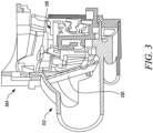
- the operating mechanism 122 is actuated to the fired state from the primed state. More particularly, during inhalation, the airflow caused by inhalation may move a vane 130 (see FIG. 3 ) of the dispensing mechanism 118 which releases the catch and allows the rocker to rotate. As depicted in FIG.
- a pressure differential in the actuator housing 102 causes the canister to displace relative to the valve stem.
- the medicament contained within the metering chamber of the canister is accordingly released in response to the patient's inspiration.
- the medicament released from the canister enters this air flow.
- a plume of the medicament dispensed through the dispensing mechanism 118 is inhaled by the patient through the mouthpiece 112.
- the inhaler 100 may also include an integrated dose counter that may assist in indicating to the patient when the medicament in the canister is about to deplete and provide health monitoring data to health personnel.
- the lever 124 After inhalation of the metered dose of the medicament by the patient, the lever 124 needs to be returned to its closed position, such that the operating mechanism 122 (see FIG. 4 ) is actuated to the reset state. It should be noted that the metering valve returns to the deactivated position after the operating mechanism 122 is actuated to the reset state. Thus, to avoid potential for damage to the metering valve, the operating mechanism 122 can be actuated to the reset state by returning the lever 124 to the closed position after using the inhaler 100. As depicted in FIG. 7 , the present disclosure is directed towards a warning system 700 for use with the inhaler 100.
- the warning system 700 may include a discreet electronic based solution for alerting the patient to actuate the operating mechanism 122 to the reset state after use in a situation where the patient might forget to reset the operating mechanism 122.
- the warning system 700 generates a warning 701 to alert the patient to actuate the operating mechanism 122 to the reset state.
- the warning 701 is at least one of an optical warning, an audio warning, and a haptic warning.
- the warning system 700 includes a switch 702 that is actuated upon actuation of the operating mechanism 122 from the primed state to the fired state.
- the switch 702 is configured to activate a control circuit 704 upon actuation.
- the switch 702 may embody a micro-switch.
- the warning system 700 includes a flange member 706 operatively coupled to the operating mechanism 122.
- the flange member 706 is movable upon actuation of the operating mechanism 122 from the primed state to the fired state to actuate the switch 702.
- the flange member 706 has a generally hollow cylindrical body 708 having a flange portion 710 that selectively contacts the switch 702 based on the movement of the flange member 706.
- the switch 702 is operatively coupled to the control circuit 704 of the warning system 700.
- the control circuit 704 includes a Printed Circuit Board (PCB) 730.
- the switch 702 may be positioned on the PCB 730.
- the switch 702 may be positioned approximately at a central portion of the PCB 730 on a first surface 714 defined by the PCB 730.
- the PCB 730 and the switch 702 are positioned such that the flange member 706 actuates the switch 702 based upon actuation of the operating mechanism 122 from the primed state to the fired state.
- the control circuit 704 is activated upon actuation of the operating mechanism 122 from the primed state to the fired state. Thus, the control circuit 704 and the switch 702 are in an activated state when the operating mechanism 122 is in the fired state. Further, the control circuit 704 is deactivated upon actuation of the operating mechanism 122 from the fired state to the reset state.
- the switch 702 selectively connects the control circuit 704 to a power source 732. When the switch 702 is off, the control circuit 704 is disconnected from the power source 732. Whereas, when the switch 702 is on, the control circuit 704 is connected to the power source 732, thereby activating the control circuit 704.
- the control circuit 704 may embody a single microprocessor or multiple microprocessors for receiving signals from components of the warning system 700. Numerous commercially available microprocessors may be configured to perform the functions of the control circuit 704.
- the control circuit 704 may further include a memory to store data and algorithms therein.
- the housing portion 104 defines a pocket 716 that receives the switch 702 and the PCB 730.
- the pocket 716 is defined at an outer surface 718 of the housing portion 104.
- the pocket 716 defines a slot 720 that receives the switch 702 such that the switch 702 projects inwards on assembly of the inhaler 100 to allow the flange member 706 to contact and actuate the switch 702.
- a shape and dimensions of the pocket 716 are decided based on a shape and dimensions of the PCB 730.
- the pocket 716 defines a length "L1" (depicted in FIG. 13 ), a breadth "B1" (depicted in FIG. 13 ), and a depth "D1" (depicted in FIG.
- the length “L1", the breadth “B1”, and the depth “D1” is generally greater than the length “L2" (depicted in FIG. 10 ), the breadth "B2” (depicted in FIG. 10 ), and the depth (not depicted) of the PCB 730 of the control circuit 704 to receive the PCB 730 therein.
- the depth “D2" is defined between the first surface 714 and a second surface 728 of the PCB 730.
- the warning system 700 includes an alert device 722.
- the alert device 722 is communicably coupled to the control circuit 704 and is configured to generate the warning 701.
- the control circuit 704 is configured to control the alert device 722 to generate the warning 701 until the operating mechanism 122 has been actuated from the fired state to the reset state. Further, the control circuit 704 is configured to control the alert device 722 to generate the warning 701 after a predetermined time delay from the actuation of the operating mechanism 122 to the fired state.
- the predetermined time delay is variable. Such a predetermined but variable time delay may be based on patient preferences and aims at avoiding false warnings.
- the alert device 722 is at least one of an optical device, an audio device, and a haptic device.
- the alert device 722 may include a single output device or a combination of output devices that generate the warning 701.
- the alert device 722 of the illustrated example includes the optical device 724 and the audio device 726.
- the optical device 724 is a Light Emitting Diode (LED) wherein the warning 701 is issued based on illumination of the LED.
- the audio device 726 is a buzzer wherein the warning 701 is issued based on a sound generated by the buzzer.
- the optical and audio devices 724, 726 may include any other known output device that issues the warning 701, without limiting the scope of the present disclosure.
- the optical device 724 and the audio device 726 may be positioned on the second surface 728 of the PCB 730.
- the alert device 722 may also include the haptic device that provides a haptic vibration to the patient to issue the warning 701.
- the audio device 726 may provide both an audio warning and a vibrational warning. It should be noted that a nature of the warning 701 may be customized based on patient preferences, and the patient may have an option to program and vary the nature of the warning 701 to achieve maximum impact in terms of alerting the patient to actuate the operating mechanism 122 to the reset state.
- the control circuit 704 is configured to control the alert device 722 to generate a first warning 1602 and a second warning 1604 after the first warning 1602.
- the first warning 1602 is generated after a first time delay "T1" from the actuation of the operating mechanism 122 to the fired state.
- the first time delay "T1" is approximately equal to 15 seconds. In other embodiments, the first time delay is about 5 seconds, about 10 seconds, or about 30 seconds.
- the first time delay "T1" is decided such that the first warning 1602 is generated only after an intended amount of the metered dose is released from the canister.
- the first warning 1602 comprises a plurality of first blips 1606 having a first amplitude and a first frequency. That is, each blip is a short sound with a specific frequency and they are repeated in a series having a predetermined pattern to draw attention.
- the plurality of first blips 1606 may be embodied as pre-warning blips that are issued before the second warning 1604 is issued.
- the plurality of first blips 1606 may provide improved user acceptance as the blips are short and may have a relatively low frequency to bring the patient's attention to a current state of the operating mechanism 122, thus the patient can actuate the operating mechanism 122 to the reset state in a discreet manner before the second warning 1604 is issued.
- the first warning 1602 issued by the warning system 700 should not distract or attract attention of other people present in the area.
- a second warning 1604 is generated after a second time delay "T2" from an end of the first time delay "T1".
- the second time delay "T2" is approximately equal to 10 seconds.
- the second time delay is about 5 seconds, about 20 seconds, about 30 seconds, or about 1 minute.
- the second warning 1604 may comprise a plurality of second blips 1608 having a second amplitude and a second frequency. The second amplitude may be greater than the first amplitude and/or the second frequency may be greater than the first frequency. This may aid in drawing attention to the need to reset the operating mechanism if the first warning was not observed.
- the second warning 1604 comprises a continuous audio warning. The second warning 1604 may be generated until the operating mechanism 122 has been actuated from the fired state to the reset state.
- the control circuit 704 is further configured to control the alert device 722 to generate a third warning 1610 after the second warning 1604.
- the third warning 1610 is generated after a third time delay "T3" from an end of the second time delay "T2".
- the third time delay "T3" is approximately equal to 10 seconds.
- the third time delay is about 5 seconds, about 20 seconds, about 30 seconds, or about 1 minute.
- the third warning 1610 may comprise a continuous audio warning having a third amplitude that is greater than the second amplitude and/or a third frequency that is greater than or equal to the second amplitude.
- the third warning 1610 may continue until the operating mechanism 122 is actuated from the fired state to the reset state.
- one or more of the first warning 1602, the second warning 1604, and the third warning 1610 are repeated for a plurality of cycles until the operating mechanism 122 has been actuated from the fired state to the reset state.
- one or more of the first frequency and the second frequency are varied across a plurality of cycles of the first and second warnings 1602, 1604. More particularly, the amplitudes of the first, second, and/or third warnings 1602, 1604, 1610 and/or the frequencies of the first and/or second warnings 1602, 1604 may be different for different cycles. In some embodiments the amplitudes and/or frequencies of the first, second, and/or third warnings may be varied within any given cycle.
- a plot 1702 illustrating a second warning strategy implemented by the warning system 700 is illustrated.
- the control circuit 704 is configured to repeat each of the first, second, and third warnings 1602, 1604, 1610 for a plurality of cycles until the operating mechanism 122 has been actuated from the fired state to the reset state.
- each of the first, second, and third warnings 1602, 1604, 1610 is repeated for a first cycle 1702 and a second cycle 1704.
- the first, second, and third warnings 1602, 1604, 1610 may be repeated for more than two cycles, without any limitations.
- a frequency of the second cycle 1704 increases after the first cycle 1702, such that the frequency of the second cycle 1704 is greater than a frequency of the first cycle 1702, and so on.
- the third warning 1610 may continue until the patient resets the operating mechanism 122. For example, the third warning 1610 may continue after the second cycle 1704 until the patient resets the operating mechanism 122.
- a total number of the cycles, the amplitudes of the first, second, and/or third warnings 1602, 1604, 1610, the frequencies of the first and/or second warnings 1602, 1604, and the first, second, and third time delay "T1", "T2", and “T3" may be varied based on preferences of the patient using the inhaler 100 and this information may be stored in the memory associated with the control circuit 704.
- the warning system 700 also includes the power source 732, such as a battery, to power various components of the warning system 700 such as the control circuit 704 and the alert device 722.
- the power source 732 may include any other power source, such as one or more button cells. Further, the warning system 700 may receive power from the power source 732 only when the operating mechanism 122 is in the primed state and the fired state, thus the warning system 700 has a longer shelf life.
- FIG. 18 illustrates a method 1800 of generating the warning 701 after use of the inhaler 100.
- the warning 701 is at least one of the optical warning, the audio warning, and the haptic warning.
- the inhaler 100 includes the operating mechanism 122 that is configured to be actuated to the reset state, the primed state, and the fired state. The inhaler 100 dispenses the metered dose of the medicament upon actuation of the operating mechanism 122 from the primed state to the fired state.
- the control circuit 704 is activated upon actuation of the operating mechanism 122 from the primed state to the fired state. More particularly, the flange member 706 moves upon actuation of the operating mechanism 122 from the primed state to the fired state to actuate the switch 702.
- the switch 702 is actuated upon actuation of the operating mechanism 122 from the primed state to the fired state, wherein the switch 702 is configured to activate the control circuit 704 upon actuation. More particularly, the switch 702 selectively connects the control circuit 704 to the power source 732. When the switch 702 is off, the control circuit 704 is disconnected from the power source 732. When the switch 702 is on, the power source 732 is connected to the control circuit 704, thereby activating the control circuit 704.
- the alert device 722 generates the warning 701 until the operating mechanism 122 has been actuated from the fired state to the reset state. Further, the control circuit 704 is deactivated upon actuation of the operating mechanism 122 from the fired state to the reset state. The alert device 722 is controlled by the control circuit 704. The warning 701 is generated after the predetermined time delay from the actuation of the operating mechanism 122 to the fired state. The predetermined time delay is variable.
- generating the warning 701 includes generating of the first warning 1602 and the second warning 1604.
- the first warning 1602 includes the plurality of blips and the second warning 1604 includes the continuous audio warning.
- the second warning 1604 is generated until the operating mechanism 122 has been actuated from the fired state to the reset state. Further, the first warning 1602 is generated after the first time delay "T1" from the actuation of the operating mechanism 122 to the fired state.
- the first warning 1602 includes the plurality of first blips having the first amplitude and the first frequency. Further, the second warning 1604 is generated after the second time delay "T2" from the end of the first time delay "T1".
- the second warning 1604 includes the plurality of second blips having the second amplitude and the second frequency, the second amplitude being greater than the first amplitude, and the second frequency being greater than the first frequency. In one example, one or more of the first frequency and the second frequency are varied across the plurality of cycles.
- generating the warning 701 includes generating the third warning 1610 after the second warning 1604.
- the third warning 1610 is generated after the third time delay "T3" from the end of the second time delay "T2".
- the third warning 1610 includes the continuous audio warning having the third amplitude greater than the second amplitude.
- one or more of the first warning 1602, the second warning 1604, and the third warning 1610 are repeated for the plurality of cycles until the operating mechanism 122 has been actuated from the fired state to the reset state.
- the warning system 700 described herein provides a low-cost and easy to implement solution for minimizing the possibility of damage to the metering valve which might occur if the operating mechanism 122 is not actuated to the reset state. Further, the warning system 700 may be implemented in a way that does not increase a size of the inhaler 100 as the components of the warning system 700 may be compact and accommodated within the actuator housing 102 without increasing a size of the actuator housing 102.
- the warning system 700 described above may form a part of an electronic inhaler such as described in International Patent Application Publication WO 2017/112400 , "Medicinal Inhalers.”
- the teachings of the present disclosure can be applied to both electronic adherence monitoring addon and integrated add-in inhalation devices. This disclosure helps in providing valuable feedback to both the patients and the health care professionals thereby improving adherence monitoring.
- a functionality of the warning system 700 may be expanded to record a dose event with a timestamp that may be communicated to a data collection infrastructure, which in turn may assist in improving patient outcome and compliance.
Landscapes
- Health & Medical Sciences (AREA)
- Engineering & Computer Science (AREA)
- Life Sciences & Earth Sciences (AREA)
- Anesthesiology (AREA)
- Pulmonology (AREA)
- Biomedical Technology (AREA)
- Heart & Thoracic Surgery (AREA)
- Hematology (AREA)
- Animal Behavior & Ethology (AREA)
- General Health & Medical Sciences (AREA)
- Public Health (AREA)
- Veterinary Medicine (AREA)
- Bioinformatics & Cheminformatics (AREA)
- Biophysics (AREA)
- Emergency Medicine (AREA)
- Infusion, Injection, And Reservoir Apparatuses (AREA)
Description
- The present disclosure generally relates to inhalation devices and, more particularly, to inhalers having a warning system for generating a warning and a method of generating the warning.
- Inhalers for pulmonary delivery are designed to deliver a medicament to an oral cavity of a patient. Such inhalers can include a breath-actuated trigger mechanism that delivers the medicament based on an inhalation of the patient. Based on the inhalation of the patient, a metered amount of the medicament is introduced into an orifice of the inhaler by a metering valve. The metering valve is in selective fluid communication with a fluid source, such as a canister, that holds the medicament. From the orifice, the medicament enters a mouthpiece of the inhaler.
-
WO 2020/161423 A1 is a document that was filed before the priority date of the present patent document and was published after the filing date of the present patent document.WO 2020/161423 A1 discloses a device for dispensing a fluid product synchronized with inhalation. -
WO 2016/030521 A1 discloses an inhaler including a mouthpiece cover, a pressure sensor, a first indicator and a second indicator. The first indicator may be configured to indicate based on a state of the cover, and the second indicator may be configured to indicate based on an output of the pressure sensor. For example, when the mouthpiece cover opens, the first indicator illuminates and a dose of medication may be transferred from a reservoir to a dosing cup. The second indicator illuminates if an amount of inhaled medication reaches a predetermined threshold for successful inhalation. - Other inhalers of the prior art are shown in
WO 2018/149620 A1 ,WO 2008/070516 A2 andWO 2017/112451 A1 . - In one aspect, the present disclosure relates to a warning system for use with an inhaler. The inhaler includes an operating mechanism that is configured to be actuated to a reset state, a primed state, and a fired state. The inhaler dispenses a metered dose of a medicament upon actuation of the operating mechanism from the primed state to the fired state. The warning system includes a control circuit that is activated upon actuation of the operating mechanism from the primed state to the fired state. The warning system also includes an alert device communicably coupled to the control circuit and configured to generate a warning. Further, the control circuit is configured to control the alert device to generate the warning until the operating mechanism has been actuated from the fired state to the reset state. The reset state is a state in which a lever is returned to a closed position after inhalation of the metered dose of the medicament by a patient, and a metering valve is returned to a deactivated position. The primed state is a state in which the lever is rotated to an open position, a spring compresses and pushes on a canister that contains the medicament, and the canister remains static. The fired state is a state in which the lever remains in the open position, and upon inhalation by the patient through a mouthpiece, energy stored in the spring depresses the canister, which activates the metering valve, and the metered dose of the medicament is released.
- In another aspect, the present disclosure relates to an inhaler for dispensing a medicament. The inhaler includes an operating mechanism that is configured to be actuated to a reset state, a primed state, and a fired state. The inhaler includes a dispensing mechanism configured to dispense a metered dose of the medicament upon actuation of the operating mechanism from the primed state to the fired state. The inhaler also includes the above-described warning system.
- In another aspect, the present disclosure relates to a method of generating a warning after use of an inhaler. The inhaler includes an operating mechanism that is configured to be actuated to a reset state, a primed state, and a fired state. The inhaler dispenses a metered dose of a medicament upon actuation of the operating mechanism from the primed state to the fired state. The method includes activating a control circuit upon actuation of the operating mechanism from the primed state to the fired state. The method also includes generating a warning by an alert device until the operating mechanism has been actuated from the fired state to the reset state. Further, the alert device is controlled by the control circuit. The reset state is a state in which a lever is returned to a closed position after inhalation of the metered dose of the medicament by a patient, and a metering valve is returned to a deactivated position. The primed state is a state in which the lever is rotated to an open position, a spring compresses and pushes on a canister that contains the medicament, and the canister remains static. The fired state is a state in which the lever remains in the open position, and upon inhalation by the patient through a mouthpiece, energy stored in the spring depresses the canister, which activates the metering valve, and the metered dose of the medicament is released.
- Exemplary embodiments disclosed herein may be more completely understood in consideration of the following detailed description in connection with the following figures. The figures are not necessarily drawn to scale. Like numbers used in the figures refer to like components. However, it will be understood that the use of a number to refer to a component in a given figure is not intended to limit the component in another figure labeled with the same number.
-
FIG. 1 is a perspective view of an inhaler in a reset state according to embodiments of the present disclosure; -
FIG. 2 is a perspective view of the inhaler depicted inFIG. 1 in a primed state; -
FIG. 3 is a sectional view of a dispensing mechanism associated with the inhaler depicted inFIG. 1 according to embodiments of the present disclosure; -
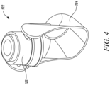
FIG. 4 is a perspective view of an operating mechanism associated with the inhaler depicted inFIG. 1 according to embodiments of the present disclosure; -
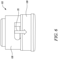
FIGS. 5 and6 illustrate operation of the operating mechanism associated with the inhaler depicted inFIG. 1 according to embodiments of the present disclosure; -
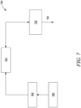
FIG. 7 is a block diagram illustrating a warning system associated with the inhaler depicted inFIG. 1 according to embodiments of the present disclosure; -
FIG. 8 is a perspective view of a flange member associated with the warning system depicted inFIG. 7 according to embodiments of the present disclosure; -
FIG. 9 is a sectional view of the inhaler showing the flange member according to embodiments of the present disclosure; -
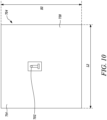
FIG. 10 illustrates a switch and a control circuit associated with the warning system depicted inFIG. 7 according to embodiments of the present disclosure; -
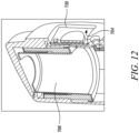
FIGS. 11 and12 are sectional views of a portion of the inhaler illustrating the flange member associated with the warning system depicted inFIG. 7 according to embodiments of the present disclosure; -
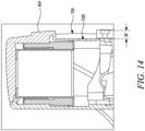
FIGS. 13 and14 illustrate different views of a pocket that receives the control circuit associated with the warning system depicted inFIG. 7 according to embodiments of the present disclosure; -
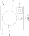
FIG. 15 illustrates an alert device and the control circuit associated with the warning system depicted inFIG. 7 according to embodiments of the present disclosure; -
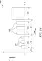
FIG. 16 illustrates a first warning strategy implemented by the warning system depicted inFIG. 7 according to embodiments of the present disclosure; -
FIG. 17 illustrates a second warning strategy implemented by the warning system depicted inFIG. 7 according to embodiments of the present disclosure; and -
FIG. 18 is a flowchart for a method of generating a warning after use of the inhaler. - In the following description, reference is made to the accompanying figures that form a part thereof and in which various embodiments are depicted by way of illustration. It is to be understood that other embodiments are contemplated and may be made without departing from the scope or spirit of the present disclosure. The following detailed description, therefore, is not to be taken in a limiting sense.
- The present disclosure will be described with respect to particular embodiments and with reference to certain drawings, but the disclosure is not limited thereto. The drawings described are only schematic and are non-limiting. In the drawings, the size of some of the elements may for illustrative purposes be exaggerated and not drawn to scale.
- It will be understood that the terms "vertical", "horizontal", "top", "bottom", "above", "below", "left", "right" etc. as used herein refer to particular orientations of the figures and these terms are not limitations to the specific embodiments described herein.
- Inhalers can comprise a canister-retaining or tubular housing portion and a tubular mouthpiece portion, the tubular mouthpiece portion being angled with respect to the tubular housing portion. An air inlet is defined proximal to at least one of an upper end and a lower end of the tubular housing portion. Further, a dispensing mechanism is disposed within the tubular housing portion that dispenses a medicament from a canister or reservoir of the inhaler. The dispensing mechanism includes a metering valve that activates during delivery of the medicament. The metering valve needs to be reset after each use to position it so that it can later be refilled from the reservoir to provide the next dose. In operation of the inhaler, a plume of the medicament is dispensed by the dispensing mechanism into the tubular mouthpiece portion and is inhaled by a patient through the tubular mouthpiece portion. However, the metering valve may not be reset directly after such use and may be susceptible to damage if left in the fired state for an extended period.
-
FIG. 1 illustrates a perspective view of aninhaler 100 for dispensing a medicament to a patient. Theinhaler 100 may be embodied as an electronic inhaler. Further, theinhaler 100 may include an onboard power source (not depicted), such as batteries or cells, that powers various electronic components of theinhaler 100. Theinhaler 100 may be embodied as a Pressurized Metered-Dose Inhaler (pMDI). - In the illustrated embodiment, the
inhaler 100 is a breath-actuated inhaler. In such a case, a metering valve (not depicted) may be actuated by a pressure differential created by inhalation of a patient to automatically dispense a spray of the medicament without any manual intervention. Theinhaler 100 includes anactuator housing 102 for holding the medicament. Theactuator housing 102 includes a housing portion 104 (depicted inFIG. 3 ). Thehousing portion 104 may have a substantially hollow structure and is tubular in shape. - The
actuator housing 102 also includes acover member 106 that covers thehousing portion 104. Thecover member 106 defines anouter surface 108. Theouter surface 108 may define a grip section (not depicted). The grip section is defined proximate to a bottom end of thecover member 106. The grip section allows a user to grip theinhaler 100 while using theinhaler 100. The grip section may essentially be a set of protrusions, a set of indents, or a sleeve providing a better gripping surface compared to theouter surface 108, or any other such structural arrangement. Further, theactuator housing 102 includes an air inlet (not depicted) for receiving the air flow. The air inlet may be defined at an upper end or a lower end of theactuator housing 102. Theactuator housing 102 includes an air inlet cover (not depicted) that defines the air inlet. The air inlet cover may be embodied as a grille. - Referring to
FIG. 2 , theinhaler 100 includes amouthpiece 112. Themouthpiece 112 is embodied as a generally tubular portion extending from theactuator housing 102 and may have a substantially hollow structure. Themouthpiece 112 is joined to thehousing portion 104. In an example, themouthpiece 112 is angled with respect to theactuator housing 102. Themouthpiece 112 may have a circular cross-section or a non-circular cross-section such as an elliptical or oblong cross-section. A user or the patient may put at least a part of themouthpiece 112 into his mouth for using theinhaler 100. - A canister (not depicted) is removably received within the
housing portion 104. The canister contains a fluid formulated with the medicament and may be embodied as an aerosol canister. In another embodiment, the fluid formulated with the medicament may be stored in a reservoir. The canister may have a generally cylindrical structure. The canister releases a predetermined amount of the medicament based on an actuation of adispensing mechanism 118. Referring toFIG. 3 , thedispensing mechanism 118 is configured to dispense a metered dose of the medicament as per requirements. Thedispensing mechanism 118 includes the metering valve. The predetermined amount of the medicament passes through the metering valve upon activation of the metering valve. When activated, the metering valve is in fluid communication with the canister. The metering valve meters an amount of the medicament exiting the canister corresponding to a single spray pattern or spray plume. Thedispensing mechanism 118 further includes a valve stem (not depicted) extending from the metering valve and a nozzle block (not depicted) having a stem socket. The nozzle block sits at a closed bottom end of theactuator housing 102. The stem socket is provided for receiving the valve stem. Further, the stem socket includes an exit orifice communicating with the mouthpiece 112 (depicted inFIG. 2 ) of theinhaler 100. - As depicted in
FIG. 4 , theinhaler 100 includes anoperating mechanism 122. Theoperating mechanism 122 is configured to be actuated to a reset state, a primed state, and a fired state. Theinhaler 100 dispenses the metered dose of the medicament upon actuation of theoperating mechanism 122 from the primed state to the fired state. More particularly, thedispensing mechanism 118 is configured to dispense the metered dose of the medicament upon actuation of theoperating mechanism 122 from the primed state to the fired state. Theoperating mechanism 122 is said to be in the reset state when theinhaler 100 is not in operation and the metering valve is in a deactivated or closed position. Further, theoperating mechanism 122 is said to be in the fired state when theinhaler 100 is in operation and the metering valve is in an activated or open position. The primed state of theoperating mechanism 122 will be explained later in this section. - The
operating mechanism 122 includes alever 124. Thelever 124 is pivotable between a closed position and an open position. Theoperating mechanism 122 may be in the primed state or the fired state when thelever 124 is in the open position. Whereas, theoperating mechanism 122 is said to be in the reset state when thelever 124 is in the closed position. Further, thelever 124 performs a function of a dust cap by isolating the mouthpiece 112 (seeFIG. 2 ) from outside environment when theinhaler 100 is not in use. Theoperating mechanism 122 also includes acylinder 126 that is received within theactuator housing 102. Thecylinder 126 is coupled to thelever 124 such that an operation of thelever 124 between the closed and open positions causes thecylinder 126 to reciprocate within theactuator housing 102. - Referring to
FIG. 5 , theoperating mechanism 122 includes a spring 128 (depicted schematically inFIG. 5 ) that is operatively coupled with thecylinder 126. In use, the patient may rotate the lever 124 (seeFIGS. 2 and4 ) to the open position and insert the exposedmouthpiece 112 into their mouth. At such an instance, theoperating mechanism 122 has been actuated to the primed state. The rotation of thelever 124 causes an off-center cam (not depicted) to compress thespring 128, as illustrated by arrow "P1". Thespring 128 compresses and pushes on the canister via thecylinder 126. However, the canister remains static and may be prevented from moving by a rocker (not depicted) which is held in place by a catch (not depicted). The rocker and the catch may form a part of thedispensing mechanism 118. On inhalation by the patient through themouthpiece 112, theoperating mechanism 122 is actuated to the fired state from the primed state. More particularly, during inhalation, the airflow caused by inhalation may move a vane 130 (seeFIG. 3 ) of thedispensing mechanism 118 which releases the catch and allows the rocker to rotate. As depicted inFIG. 6 , when theoperating mechanism 122 is in the fired state, energy stored in thespring 128 during the priming state depresses the canister via thecylinder 126, as illustrated by arrow "P2", which in turn activates the metering valve, based on which the medicament contained within the canister is released. - Referring to
FIG. 2 , on inhalation by the patient through themouthpiece 112, a pressure differential in theactuator housing 102 causes the canister to displace relative to the valve stem. The medicament contained within the metering chamber of the canister is accordingly released in response to the patient's inspiration. During the patient's inspiration, air flows from the air inlet, through theactuator housing 102. The medicament released from the canister enters this air flow. Thus, during operation of theinhaler 100, a plume of the medicament dispensed through thedispensing mechanism 118 is inhaled by the patient through themouthpiece 112. Theinhaler 100 may also include an integrated dose counter that may assist in indicating to the patient when the medicament in the canister is about to deplete and provide health monitoring data to health personnel. - After inhalation of the metered dose of the medicament by the patient, the
lever 124 needs to be returned to its closed position, such that the operating mechanism 122 (seeFIG. 4 ) is actuated to the reset state. It should be noted that the metering valve returns to the deactivated position after theoperating mechanism 122 is actuated to the reset state. Thus, to avoid potential for damage to the metering valve, theoperating mechanism 122 can be actuated to the reset state by returning thelever 124 to the closed position after using theinhaler 100. As depicted inFIG. 7 , the present disclosure is directed towards awarning system 700 for use with theinhaler 100. Thewarning system 700 may include a discreet electronic based solution for alerting the patient to actuate theoperating mechanism 122 to the reset state after use in a situation where the patient might forget to reset theoperating mechanism 122. Thewarning system 700 generates awarning 701 to alert the patient to actuate theoperating mechanism 122 to the reset state. Thewarning 701 is at least one of an optical warning, an audio warning, and a haptic warning. - The
warning system 700 includes aswitch 702 that is actuated upon actuation of theoperating mechanism 122 from the primed state to the fired state. Theswitch 702 is configured to activate acontrol circuit 704 upon actuation. Theswitch 702 may embody a micro-switch. In embodiments, as depicted inFIGS. 8 and9 , thewarning system 700 includes aflange member 706 operatively coupled to theoperating mechanism 122. Theflange member 706 is movable upon actuation of theoperating mechanism 122 from the primed state to the fired state to actuate theswitch 702. Theflange member 706 has a generally hollowcylindrical body 708 having aflange portion 710 that selectively contacts theswitch 702 based on the movement of theflange member 706. - The
switch 702 is operatively coupled to thecontrol circuit 704 of thewarning system 700. In the illustrated example, thecontrol circuit 704 includes a Printed Circuit Board (PCB) 730. In an embodiment depicted inFIG. 10 , theswitch 702 may be positioned on thePCB 730. For example, theswitch 702 may be positioned approximately at a central portion of thePCB 730 on afirst surface 714 defined by thePCB 730. As depicted inFIGS. 11 and12 , thePCB 730 and theswitch 702 are positioned such that theflange member 706 actuates theswitch 702 based upon actuation of theoperating mechanism 122 from the primed state to the fired state. Thecontrol circuit 704 is activated upon actuation of theoperating mechanism 122 from the primed state to the fired state. Thus, thecontrol circuit 704 and theswitch 702 are in an activated state when theoperating mechanism 122 is in the fired state. Further, thecontrol circuit 704 is deactivated upon actuation of theoperating mechanism 122 from the fired state to the reset state. Theswitch 702 selectively connects thecontrol circuit 704 to apower source 732. When theswitch 702 is off, thecontrol circuit 704 is disconnected from thepower source 732. Whereas, when theswitch 702 is on, thecontrol circuit 704 is connected to thepower source 732, thereby activating thecontrol circuit 704. Thecontrol circuit 704 may embody a single microprocessor or multiple microprocessors for receiving signals from components of thewarning system 700. Numerous commercially available microprocessors may be configured to perform the functions of thecontrol circuit 704. Thecontrol circuit 704 may further include a memory to store data and algorithms therein. - As depicted in
FIGS. 13 and14 , thehousing portion 104 defines apocket 716 that receives theswitch 702 and thePCB 730. Thepocket 716 is defined at anouter surface 718 of thehousing portion 104. Thepocket 716 defines aslot 720 that receives theswitch 702 such that theswitch 702 projects inwards on assembly of theinhaler 100 to allow theflange member 706 to contact and actuate theswitch 702. A shape and dimensions of thepocket 716 are decided based on a shape and dimensions of thePCB 730. Thepocket 716 defines a length "L1" (depicted inFIG. 13 ), a breadth "B1" (depicted inFIG. 13 ), and a depth "D1" (depicted inFIG. 14 ) from theouter surface 718 of thehousing portion 104. Further, the length "L1", the breadth "B1", and the depth "D1" is generally greater than the length "L2" (depicted inFIG. 10 ), the breadth "B2" (depicted inFIG. 10 ), and the depth (not depicted) of thePCB 730 of thecontrol circuit 704 to receive thePCB 730 therein. The depth "D2" is defined between thefirst surface 714 and asecond surface 728 of thePCB 730. When theinhaler 100 is assembled, thepocket 716 is covered by thecover member 106 so that sensitive components of thewarning system 700 are isolated from the outside environment. - Referring to
FIG. 5 , thewarning system 700 includes analert device 722. Thealert device 722 is communicably coupled to thecontrol circuit 704 and is configured to generate thewarning 701. Thecontrol circuit 704 is configured to control thealert device 722 to generate thewarning 701 until theoperating mechanism 122 has been actuated from the fired state to the reset state. Further, thecontrol circuit 704 is configured to control thealert device 722 to generate thewarning 701 after a predetermined time delay from the actuation of theoperating mechanism 122 to the fired state. In some embodiments, the predetermined time delay is variable. Such a predetermined but variable time delay may be based on patient preferences and aims at avoiding false warnings. - In some embodiments, the
alert device 722 is at least one of an optical device, an audio device, and a haptic device. In some embodiments, thealert device 722 may include a single output device or a combination of output devices that generate thewarning 701. As depicted inFIG. 15 , thealert device 722 of the illustrated example includes theoptical device 724 and theaudio device 726. Theoptical device 724 is a Light Emitting Diode (LED) wherein thewarning 701 is issued based on illumination of the LED. Theaudio device 726 is a buzzer wherein thewarning 701 is issued based on a sound generated by the buzzer. Alternatively, the optical andaudio devices warning 701, without limiting the scope of the present disclosure. Theoptical device 724 and theaudio device 726 may be positioned on thesecond surface 728 of thePCB 730. Further, thealert device 722 may also include the haptic device that provides a haptic vibration to the patient to issue thewarning 701. In some embodiments, theaudio device 726 may provide both an audio warning and a vibrational warning. It should be noted that a nature of thewarning 701 may be customized based on patient preferences, and the patient may have an option to program and vary the nature of the warning 701 to achieve maximum impact in terms of alerting the patient to actuate theoperating mechanism 122 to the reset state. - Referring now to
FIG. 16 , aplot 1602 illustrating a first warning strategy of thewarning system 700 will be described. In an example, thecontrol circuit 704 is configured to control thealert device 722 to generate afirst warning 1602 and asecond warning 1604 after thefirst warning 1602. In an embodiment, thefirst warning 1602 is generated after a first time delay "T1" from the actuation of theoperating mechanism 122 to the fired state. In an example, the first time delay "T1" is approximately equal to 15 seconds. In other embodiments, the first time delay is about 5 seconds, about 10 seconds, or about 30 seconds. The first time delay "T1" is decided such that thefirst warning 1602 is generated only after an intended amount of the metered dose is released from the canister. In an example, thefirst warning 1602 comprises a plurality offirst blips 1606 having a first amplitude and a first frequency. That is, each blip is a short sound with a specific frequency and they are repeated in a series having a predetermined pattern to draw attention. For example, the plurality offirst blips 1606 may be embodied as pre-warning blips that are issued before thesecond warning 1604 is issued. The plurality offirst blips 1606 may provide improved user acceptance as the blips are short and may have a relatively low frequency to bring the patient's attention to a current state of theoperating mechanism 122, thus the patient can actuate theoperating mechanism 122 to the reset state in a discreet manner before thesecond warning 1604 is issued. Thus, in such situations, thefirst warning 1602 issued by thewarning system 700 should not distract or attract attention of other people present in the area. - In another embodiment, a
second warning 1604 is generated after a second time delay "T2" from an end of the first time delay "T1". In an example, the second time delay "T2" is approximately equal to 10 seconds. In other embodiments, the second time delay is about 5 seconds, about 20 seconds, about 30 seconds, or about 1 minute. Thesecond warning 1604 may comprise a plurality ofsecond blips 1608 having a second amplitude and a second frequency. The second amplitude may be greater than the first amplitude and/or the second frequency may be greater than the first frequency. This may aid in drawing attention to the need to reset the operating mechanism if the first warning was not observed. In another example, thesecond warning 1604 comprises a continuous audio warning. Thesecond warning 1604 may be generated until theoperating mechanism 122 has been actuated from the fired state to the reset state. - The
control circuit 704 is further configured to control thealert device 722 to generate athird warning 1610 after thesecond warning 1604. Thethird warning 1610 is generated after a third time delay "T3" from an end of the second time delay "T2". In an example, the third time delay "T3" is approximately equal to 10 seconds. In other embodiments, the third time delay is about 5 seconds, about 20 seconds, about 30 seconds, or about 1 minute. Thethird warning 1610 may comprise a continuous audio warning having a third amplitude that is greater than the second amplitude and/or a third frequency that is greater than or equal to the second amplitude. In an example, thethird warning 1610 may continue until theoperating mechanism 122 is actuated from the fired state to the reset state. - In another example, one or more of the
first warning 1602, thesecond warning 1604, and thethird warning 1610 are repeated for a plurality of cycles until theoperating mechanism 122 has been actuated from the fired state to the reset state. Further, in some embodiments, one or more of the first frequency and the second frequency are varied across a plurality of cycles of the first andsecond warnings third warnings second warnings - Referring now to
FIG. 17 , aplot 1702 illustrating a second warning strategy implemented by thewarning system 700 is illustrated. As depicted, thecontrol circuit 704 is configured to repeat each of the first, second, andthird warnings operating mechanism 122 has been actuated from the fired state to the reset state. In this example, each of the first, second, andthird warnings first cycle 1702 and asecond cycle 1704. However, the first, second, andthird warnings second cycle 1704 increases after thefirst cycle 1702, such that the frequency of thesecond cycle 1704 is greater than a frequency of thefirst cycle 1702, and so on. Further, in some examples, thethird warning 1610 may continue until the patient resets theoperating mechanism 122. For example, thethird warning 1610 may continue after thesecond cycle 1704 until the patient resets theoperating mechanism 122. It should be noted that a total number of the cycles, the amplitudes of the first, second, and/orthird warnings second warnings inhaler 100 and this information may be stored in the memory associated with thecontrol circuit 704. - Additionally, the
warning system 700 also includes thepower source 732, such as a battery, to power various components of thewarning system 700 such as thecontrol circuit 704 and thealert device 722. Thepower source 732 may include any other power source, such as one or more button cells. Further, thewarning system 700 may receive power from thepower source 732 only when theoperating mechanism 122 is in the primed state and the fired state, thus thewarning system 700 has a longer shelf life. -
FIG. 18 illustrates amethod 1800 of generating thewarning 701 after use of theinhaler 100. Thewarning 701 is at least one of the optical warning, the audio warning, and the haptic warning. Theinhaler 100 includes theoperating mechanism 122 that is configured to be actuated to the reset state, the primed state, and the fired state. Theinhaler 100 dispenses the metered dose of the medicament upon actuation of theoperating mechanism 122 from the primed state to the fired state. - At
step 1802, thecontrol circuit 704 is activated upon actuation of theoperating mechanism 122 from the primed state to the fired state. More particularly, theflange member 706 moves upon actuation of theoperating mechanism 122 from the primed state to the fired state to actuate theswitch 702. Thus, theswitch 702 is actuated upon actuation of theoperating mechanism 122 from the primed state to the fired state, wherein theswitch 702 is configured to activate thecontrol circuit 704 upon actuation. More particularly, theswitch 702 selectively connects thecontrol circuit 704 to thepower source 732. When theswitch 702 is off, thecontrol circuit 704 is disconnected from thepower source 732. When theswitch 702 is on, thepower source 732 is connected to thecontrol circuit 704, thereby activating thecontrol circuit 704. - At
step 1804, thealert device 722 generates thewarning 701 until theoperating mechanism 122 has been actuated from the fired state to the reset state. Further, thecontrol circuit 704 is deactivated upon actuation of theoperating mechanism 122 from the fired state to the reset state. Thealert device 722 is controlled by thecontrol circuit 704. Thewarning 701 is generated after the predetermined time delay from the actuation of theoperating mechanism 122 to the fired state. The predetermined time delay is variable. - In one example, generating the
warning 701 includes generating of thefirst warning 1602 and thesecond warning 1604. Thefirst warning 1602 includes the plurality of blips and thesecond warning 1604 includes the continuous audio warning. Thesecond warning 1604 is generated until theoperating mechanism 122 has been actuated from the fired state to the reset state. Further, thefirst warning 1602 is generated after the first time delay "T1" from the actuation of theoperating mechanism 122 to the fired state. Thefirst warning 1602 includes the plurality of first blips having the first amplitude and the first frequency. Further, thesecond warning 1604 is generated after the second time delay "T2" from the end of the first time delay "T1". Thesecond warning 1604 includes the plurality of second blips having the second amplitude and the second frequency, the second amplitude being greater than the first amplitude, and the second frequency being greater than the first frequency. In one example, one or more of the first frequency and the second frequency are varied across the plurality of cycles. - Additionally, generating the
warning 701 includes generating thethird warning 1610 after thesecond warning 1604. Thethird warning 1610 is generated after the third time delay "T3" from the end of the second time delay "T2". Thethird warning 1610 includes the continuous audio warning having the third amplitude greater than the second amplitude. In one example, one or more of thefirst warning 1602, thesecond warning 1604, and thethird warning 1610 are repeated for the plurality of cycles until theoperating mechanism 122 has been actuated from the fired state to the reset state. - The
warning system 700 described herein provides a low-cost and easy to implement solution for minimizing the possibility of damage to the metering valve which might occur if theoperating mechanism 122 is not actuated to the reset state. Further, thewarning system 700 may be implemented in a way that does not increase a size of theinhaler 100 as the components of thewarning system 700 may be compact and accommodated within theactuator housing 102 without increasing a size of theactuator housing 102. - The
warning system 700 described above may form a part of an electronic inhaler such as described in International Patent Application PublicationWO 2017/112400 , "Medicinal Inhalers." The teachings of the present disclosure can be applied to both electronic adherence monitoring addon and integrated add-in inhalation devices. This disclosure helps in providing valuable feedback to both the patients and the health care professionals thereby improving adherence monitoring. For example, a functionality of thewarning system 700 may be expanded to record a dose event with a timestamp that may be communicated to a data collection infrastructure, which in turn may assist in improving patient outcome and compliance. - Unless otherwise indicated, all numbers expressing feature sizes, amounts, and physical properties used in the specification and claims are to be understood as being modified by the term "about". Accordingly, unless indicated to the contrary, the numerical parameters set forth in the foregoing specification and attached claims are approximations that can vary depending upon the desired properties sought to be obtained by those skilled in the art utilizing the teachings disclosed herein.
- Although specific embodiments have been illustrated and described herein, it will be appreciated by those of ordinary skill in the art that a variety of alternate and/or equivalent implementations can be substituted for the specific embodiments depicted and described without departing from the scope of the present claims. This application is intended to cover any adaptations or variations of the specific embodiments discussed herein. Therefore, it is intended that this disclosure be limited only by the claims.
Claims (15)
- A warning system (700) for use with an inhaler (100), the inhaler having an operating mechanism (122) that is configured to be actuated to a reset state, a primed state, and a fired state, the inhaler dispensing (100) a metered dose of a medicament upon actuation of the operating mechanism from the primed state to the fired state, the warning system (700) comprising:a control circuit (704) that is activated upon actuation of the operating mechanism (122) from the primed state to the fired state; andan alert device (722) communicably coupled to the control circuit (704) and configured to generate a warning (701),wherein the control circuit (704) is configured to control the alert device (722) to generate the warning (701) until the operating mechanism (122) has been actuated from the fired state to the reset state,wherein the reset state is a state in which a lever (124) is returned to a closed position after inhalation of the metered dose of the medicament by a patient, and a metering valve is returned to a deactivated position,wherein the primed state is a state in which the lever (124) is rotated to an open position, a spring (128) compresses and pushes on a canister that contains the medicament, and the canister remains static, andwherein the fired state is a state in which the lever (124) remains in the open position, and upon inhalation by the patient through a mouthpiece, energy stored in the spring (128) depresses the canister, which activates the metering valve, and the metered dose of the medicament is released.
- The warning system (700) of claim 1, wherein the control circuit (704) is further configured to control the alert device (722) to generate the warning (701) after a predetermined time delay from the actuation of the operating mechanism (122) from the primed state to the fired state.
- The warning system (700) of claim 1, wherein the control circuit (704) is deactivated upon actuation of the operating mechanism (122) from the fired state to the reset state.
- The warning system (700) of claim 1, further comprising a switch (702) that is actuated upon actuation of the operating mechanism (122) from the primed state to the fired state, wherein the switch (702) is configured to activate the control circuit (704) upon actuation.
- The warning system (700) of claim 1, wherein the control circuit (704) is further configured to control the alert device (722) to generate a first warning (1602) and a second warning (1604) after the first warning (1602).
- The warning system (700) of claim 5, wherein the first warning (1602) comprises a plurality of blips.
- The warning system (700) of claim 5, wherein the second warning (1604) comprises a continuous audio warning.
- The warning system (700) of claim 5, wherein the second warning (1604) is generated until the operating mechanism (122) has been actuated from the fired state to the reset state.
- The warning system (700) of claim 5, wherein the first warning (1602) is generated after a first time delay (T1) from the actuation of the operating mechanism to the fired state.
- The warning system (700) of claim 9, wherein the second warning (1604) is generated after a second time delay (T2) from an end of the first time delay.
- The warning system (700) of claim 10, wherein the control circuit (704) is further configured to control the alert device to generate a third warning (1610) after the second warning (1604).
- The warning system (700) of claim 11, wherein the third warning (1610) is generated after a third time delay (T3) from an end of the second time delay (T2).
- The warning system (700) of claim 11, wherein:the first warning (1602) comprises a plurality of first blips having a first amplitude and a first frequency;the second warning (1604) comprises a plurality of second blips having a second amplitude and a second frequency, the second amplitude being greater than the first amplitude, and the second frequency being greater than the first frequency; andthe third warning (1610) comprises a continuous audio warning having a third amplitude greater than the second amplitude.
- An inhaler (100) for dispensing a medicament, the inhaler (100) comprising:an operating mechanism (122) that is configured to be actuated to a reset state, a primed state, and a fired state;a dispensing mechanism (118) configured to dispense a metered dose of the medicament upon actuation of the operating mechanism (122) from the primed state to the fired state; andthe warning system (700) of claim 1.
- A method of generating (1800) a warning (701) after use of an inhaler (100), the inhaler (100) having an operating mechanism (122) that is configured to be actuated to a reset state, a primed state, and a fired state, the inhaler dispensing a metered dose of a medicament upon actuation of the operating mechanism from the primed state to the fired state, the method comprising:activating (1802) a control circuit (704) upon actuation of the operating mechanism (122) from the primed state to the fired state; andgenerating (1804), by an alert device (722), a warning (701) until the operating mechanism (122) has been actuated from the fired state to the reset state, wherein the alert device (722) is controlled by the control circuit (704),wherein the reset state is a state in which a lever (124) is returned to a closed position after inhalation of the metered dose of the medicament by a patient, and a metering valve is returned to a deactivated position,wherein the primed state is a state in which the lever (124) is rotated to an open position, a spring (128) compresses and pushes on a canister that contains the medicament, and the canister remains static, andwherein the fired state is a state in which the lever (124) remains in the open position, and upon inhalation by the patient through a mouthpiece, energy stored in the spring (128) depresses the canister, which activates the metering valve, and the metered dose of the medicament is released.
Applications Claiming Priority (2)
| Application Number | Priority Date | Filing Date | Title |
|---|---|---|---|
| US201962844221P | 2019-05-07 | 2019-05-07 | |
| PCT/IB2020/054091 WO2020225666A1 (en) | 2019-05-07 | 2020-04-30 | Warning system, inhaler, and method for generating warning |
Publications (3)
| Publication Number | Publication Date |
|---|---|
| EP3965856A1 EP3965856A1 (en) | 2022-03-16 |
| EP3965856A4 EP3965856A4 (en) | 2023-05-31 |
| EP3965856B1 true EP3965856B1 (en) | 2024-08-21 |
Family
ID=73051558
Family Applications (1)
| Application Number | Title | Priority Date | Filing Date |
|---|---|---|---|
| EP20801904.2A Active EP3965856B1 (en) | 2019-05-07 | 2020-04-30 | Warning system, inhaler, and method for generating warning |
Country Status (5)
| Country | Link |
|---|---|
| US (1) | US20220203053A1 (en) |
| EP (1) | EP3965856B1 (en) |
| JP (1) | JP7434361B2 (en) |
| CN (1) | CN114144217A (en) |
| WO (1) | WO2020225666A1 (en) |
Families Citing this family (1)
| Publication number | Priority date | Publication date | Assignee | Title |
|---|---|---|---|---|
| USD960349S1 (en) * | 2019-02-04 | 2022-08-09 | Orion Corporation | Inhaler |
Family Cites Families (22)
| Publication number | Priority date | Publication date | Assignee | Title |
|---|---|---|---|---|
| FR2701399B1 (en) * | 1993-02-16 | 1995-03-31 | Valois | Portable spray device with actuation triggered by inhalation. |
| US20030192535A1 (en) * | 1999-09-24 | 2003-10-16 | Astrazeneca Ab. | Inhaler |
| JP2003047654A (en) * | 2001-05-23 | 2003-02-18 | Sekisui Chem Co Ltd | Enema tubes and catheters |
| US20020189615A1 (en) * | 2001-06-13 | 2002-12-19 | Henry Adam S. | Inhaler with dose control |
| GB0209783D0 (en) * | 2002-04-29 | 2002-06-05 | Glaxo Group Ltd | Medicament dispenser |
| US20040255936A1 (en) * | 2003-04-30 | 2004-12-23 | David Urbanus | Disposable metered dose inhaler with integrated electronic counter |
| US20050028815A1 (en) * | 2003-07-23 | 2005-02-10 | Deaton Daniel M. | Apparatus for electronic dosage counter |
| JP2007525263A (en) * | 2004-01-29 | 2007-09-06 | イコス コーポレイション | Method and apparatus for detecting blood vessel state by catheter |
| US20080178872A1 (en) * | 2006-12-01 | 2008-07-31 | Perry Genova | Dose selective breath actuated inhaler |
| US8950394B2 (en) * | 2010-01-12 | 2015-02-10 | Dance Biopharm Inc. | Preservative-free single dose inhaler systems |
| US10828434B2 (en) * | 2013-08-30 | 2020-11-10 | Adherium (Nz) Limited | Compliance monitor for a medicament inhaler |
| US9943656B2 (en) * | 2014-08-27 | 2018-04-17 | Presspart Gmbh & Co. Kg | Metered-dose inhaler counter with switch and metered-dose inhaler including such a counter |
| KR102631093B1 (en) * | 2014-08-28 | 2024-01-29 | 노턴 (워터포드) 리미티드 | Compliance monitoring module for a breath-actuated inhaler |
| US10168804B2 (en) * | 2015-09-08 | 2019-01-01 | Apple Inc. | Stylus for electronic devices |
| US11083855B2 (en) | 2015-12-21 | 2021-08-10 | Kindeva Drug Delivery L.P. | Auto-reset dose release firing systems, medicinal inhalers comprising same, and methods of using same |
| ES2915559T3 (en) * | 2016-02-17 | 2022-06-23 | Adherium Nz Ltd | Adherence monitor for a medication inhaler with cap attached |
| GB201615185D0 (en) * | 2016-09-07 | 2016-10-19 | 3M Innovative Properties Co | Reset mechanism for an inhaler |
| KR102050183B1 (en) * | 2016-11-23 | 2019-11-28 | 선전 구딕스 테크놀로지 컴퍼니, 리미티드 | Force measuring methods, devices and instruments |
| GB201702406D0 (en) | 2017-02-14 | 2017-03-29 | Norton (Waterford) Ltd | Inhalers and related methods |
| CN118203735A (en) * | 2017-10-04 | 2024-06-18 | 精呼吸股份有限公司 | Electronic respiration actuated linear type liquid drop conveying device and using method thereof |
| FR3092252B1 (en) * | 2019-02-04 | 2021-01-22 | Aptar France Sas | Fluid dispenser device synchronized with inhalation |
| FR3092251B1 (en) * | 2019-02-04 | 2021-01-22 | Aptar France Sas | Fluid dispenser device synchronized with inhalation and method of assembling said device |
-
2020
- 2020-04-30 WO PCT/IB2020/054091 patent/WO2020225666A1/en not_active Ceased
- 2020-04-30 CN CN202080034025.7A patent/CN114144217A/en active Pending
- 2020-04-30 US US17/608,580 patent/US20220203053A1/en not_active Abandoned
- 2020-04-30 EP EP20801904.2A patent/EP3965856B1/en active Active
- 2020-04-30 JP JP2021566050A patent/JP7434361B2/en active Active
Also Published As
| Publication number | Publication date |
|---|---|
| CN114144217A (en) | 2022-03-04 |
| EP3965856A1 (en) | 2022-03-16 |
| JP2022531712A (en) | 2022-07-08 |
| JP7434361B2 (en) | 2024-02-20 |
| US20220203053A1 (en) | 2022-06-30 |
| WO2020225666A1 (en) | 2020-11-12 |
| EP3965856A4 (en) | 2023-05-31 |
Similar Documents
| Publication | Publication Date | Title |
|---|---|---|
| US12357778B2 (en) | Mobile inhaler and a container for using therewith | |
| US20220388831A1 (en) | Vaporization Device | |
| CA2557002C (en) | Atomizer provided with a monitoring device for counting actuations of the atomizer | |
| JP3583569B2 (en) | Counter for fluid dispenser | |
| KR100314138B1 (en) | Metering device | |
| EP1474196B1 (en) | Methods and systems for operating an aerosol generator | |
| US6854461B2 (en) | Aerosol generator for drug formulation and methods of generating aerosol | |
| US20130319404A1 (en) | Liquid Droplet Spray Device | |
| US20020000225A1 (en) | Lockout mechanism for aerosol drug delivery devices | |
| US20060254581A1 (en) | Dose counting in metered dose inhaler | |
| US20130239957A1 (en) | Actuator devices for inhalers | |
| JP2006528520A (en) | Electronic dose counter | |
| JPH09508845A (en) | Dose metering inhaler | |
| US7458373B2 (en) | Aerosol generator for drug formulation | |
| CN115054786A (en) | Metered dose inhaler attachment, observation enhancement system and method of improving observations in using metered dose inhalers | |
| CN111163822A (en) | Fluid product dispensing device | |
| US20220203053A1 (en) | Warning system, inhaler, and method for generating warning |
Legal Events
| Date | Code | Title | Description |
|---|---|---|---|
| STAA | Information on the status of an ep patent application or granted ep patent |
Free format text: STATUS: THE INTERNATIONAL PUBLICATION HAS BEEN MADE |
|
| PUAI | Public reference made under article 153(3) epc to a published international application that has entered the european phase |
Free format text: ORIGINAL CODE: 0009012 |
|
| STAA | Information on the status of an ep patent application or granted ep patent |
Free format text: STATUS: REQUEST FOR EXAMINATION WAS MADE |
|
| 17P | Request for examination filed |
Effective date: 20211204 |
|
| AK | Designated contracting states |
Kind code of ref document: A1 Designated state(s): AL AT BE BG CH CY CZ DE DK EE ES FI FR GB GR HR HU IE IS IT LI LT LU LV MC MK MT NL NO PL PT RO RS SE SI SK SM TR |
|
| DAV | Request for validation of the european patent (deleted) | ||
| DAX | Request for extension of the european patent (deleted) | ||
| A4 | Supplementary search report drawn up and despatched |
Effective date: 20230502 |
|
| RIC1 | Information provided on ipc code assigned before grant |
Ipc: G08B 21/00 20060101ALI20230424BHEP Ipc: A61M 15/00 20060101AFI20230424BHEP |
|
| GRAP | Despatch of communication of intention to grant a patent |
Free format text: ORIGINAL CODE: EPIDOSNIGR1 |
|
| STAA | Information on the status of an ep patent application or granted ep patent |
Free format text: STATUS: GRANT OF PATENT IS INTENDED |
|
| INTG | Intention to grant announced |
Effective date: 20240313 |
|
| GRAS | Grant fee paid |
Free format text: ORIGINAL CODE: EPIDOSNIGR3 |
|
| GRAA | (expected) grant |
Free format text: ORIGINAL CODE: 0009210 |
|
| STAA | Information on the status of an ep patent application or granted ep patent |
Free format text: STATUS: THE PATENT HAS BEEN GRANTED |
|
| AK | Designated contracting states |
Kind code of ref document: B1 Designated state(s): AL AT BE BG CH CY CZ DE DK EE ES FI FR GB GR HR HU IE IS IT LI LT LU LV MC MK MT NL NO PL PT RO RS SE SI SK SM TR |
|
| REG | Reference to a national code |
Ref country code: GB Ref legal event code: FG4D |
|
| P01 | Opt-out of the competence of the unified patent court (upc) registered |
Free format text: CASE NUMBER: APP_42670/2024 Effective date: 20240719 |
|
| REG | Reference to a national code |
Ref country code: CH Ref legal event code: EP |
|
| REG | Reference to a national code |
Ref country code: IE Ref legal event code: FG4D |
|
| REG | Reference to a national code |
Ref country code: DE Ref legal event code: R096 Ref document number: 602020036316 Country of ref document: DE |
|
| REG | Reference to a national code |
Ref country code: LT Ref legal event code: MG9D |
|
| REG | Reference to a national code |
Ref country code: NL Ref legal event code: MP Effective date: 20240821 |
|
| PG25 | Lapsed in a contracting state [announced via postgrant information from national office to epo] |
Ref country code: NO Free format text: LAPSE BECAUSE OF FAILURE TO SUBMIT A TRANSLATION OF THE DESCRIPTION OR TO PAY THE FEE WITHIN THE PRESCRIBED TIME-LIMIT Effective date: 20241121 |
|
| REG | Reference to a national code |
Ref country code: AT Ref legal event code: MK05 Ref document number: 1714921 Country of ref document: AT Kind code of ref document: T Effective date: 20240821 |
|
| PG25 | Lapsed in a contracting state [announced via postgrant information from national office to epo] |
Ref country code: FI Free format text: LAPSE BECAUSE OF FAILURE TO SUBMIT A TRANSLATION OF THE DESCRIPTION OR TO PAY THE FEE WITHIN THE PRESCRIBED TIME-LIMIT Effective date: 20240821 Ref country code: NL Free format text: LAPSE BECAUSE OF FAILURE TO SUBMIT A TRANSLATION OF THE DESCRIPTION OR TO PAY THE FEE WITHIN THE PRESCRIBED TIME-LIMIT Effective date: 20240821 Ref country code: PL Free format text: LAPSE BECAUSE OF FAILURE TO SUBMIT A TRANSLATION OF THE DESCRIPTION OR TO PAY THE FEE WITHIN THE PRESCRIBED TIME-LIMIT Effective date: 20240821 Ref country code: GR Free format text: LAPSE BECAUSE OF FAILURE TO SUBMIT A TRANSLATION OF THE DESCRIPTION OR TO PAY THE FEE WITHIN THE PRESCRIBED TIME-LIMIT Effective date: 20241122 Ref country code: PT Free format text: LAPSE BECAUSE OF FAILURE TO SUBMIT A TRANSLATION OF THE DESCRIPTION OR TO PAY THE FEE WITHIN THE PRESCRIBED TIME-LIMIT Effective date: 20241223 |
|
| PG25 | Lapsed in a contracting state [announced via postgrant information from national office to epo] |
Ref country code: BG Free format text: LAPSE BECAUSE OF FAILURE TO SUBMIT A TRANSLATION OF THE DESCRIPTION OR TO PAY THE FEE WITHIN THE PRESCRIBED TIME-LIMIT Effective date: 20240821 |
|
| PG25 | Lapsed in a contracting state [announced via postgrant information from national office to epo] |
Ref country code: LV Free format text: LAPSE BECAUSE OF FAILURE TO SUBMIT A TRANSLATION OF THE DESCRIPTION OR TO PAY THE FEE WITHIN THE PRESCRIBED TIME-LIMIT Effective date: 20240821 |
|
| PG25 | Lapsed in a contracting state [announced via postgrant information from national office to epo] |
Ref country code: AT Free format text: LAPSE BECAUSE OF FAILURE TO SUBMIT A TRANSLATION OF THE DESCRIPTION OR TO PAY THE FEE WITHIN THE PRESCRIBED TIME-LIMIT Effective date: 20240821 Ref country code: IS Free format text: LAPSE BECAUSE OF FAILURE TO SUBMIT A TRANSLATION OF THE DESCRIPTION OR TO PAY THE FEE WITHIN THE PRESCRIBED TIME-LIMIT Effective date: 20241221 |
|
| PG25 | Lapsed in a contracting state [announced via postgrant information from national office to epo] |
Ref country code: HR Free format text: LAPSE BECAUSE OF FAILURE TO SUBMIT A TRANSLATION OF THE DESCRIPTION OR TO PAY THE FEE WITHIN THE PRESCRIBED TIME-LIMIT Effective date: 20240821 |
|
| PG25 | Lapsed in a contracting state [announced via postgrant information from national office to epo] |
Ref country code: RS Free format text: LAPSE BECAUSE OF FAILURE TO SUBMIT A TRANSLATION OF THE DESCRIPTION OR TO PAY THE FEE WITHIN THE PRESCRIBED TIME-LIMIT Effective date: 20241121 Ref country code: ES Free format text: LAPSE BECAUSE OF FAILURE TO SUBMIT A TRANSLATION OF THE DESCRIPTION OR TO PAY THE FEE WITHIN THE PRESCRIBED TIME-LIMIT Effective date: 20240821 |
|
| PG25 | Lapsed in a contracting state [announced via postgrant information from national office to epo] |
Ref country code: RS Free format text: LAPSE BECAUSE OF FAILURE TO SUBMIT A TRANSLATION OF THE DESCRIPTION OR TO PAY THE FEE WITHIN THE PRESCRIBED TIME-LIMIT Effective date: 20241121 Ref country code: PT Free format text: LAPSE BECAUSE OF FAILURE TO SUBMIT A TRANSLATION OF THE DESCRIPTION OR TO PAY THE FEE WITHIN THE PRESCRIBED TIME-LIMIT Effective date: 20241223 Ref country code: PL Free format text: LAPSE BECAUSE OF FAILURE TO SUBMIT A TRANSLATION OF THE DESCRIPTION OR TO PAY THE FEE WITHIN THE PRESCRIBED TIME-LIMIT Effective date: 20240821 Ref country code: NO Free format text: LAPSE BECAUSE OF FAILURE TO SUBMIT A TRANSLATION OF THE DESCRIPTION OR TO PAY THE FEE WITHIN THE PRESCRIBED TIME-LIMIT Effective date: 20241121 Ref country code: NL Free format text: LAPSE BECAUSE OF FAILURE TO SUBMIT A TRANSLATION OF THE DESCRIPTION OR TO PAY THE FEE WITHIN THE PRESCRIBED TIME-LIMIT Effective date: 20240821 Ref country code: LV Free format text: LAPSE BECAUSE OF FAILURE TO SUBMIT A TRANSLATION OF THE DESCRIPTION OR TO PAY THE FEE WITHIN THE PRESCRIBED TIME-LIMIT Effective date: 20240821 Ref country code: IS Free format text: LAPSE BECAUSE OF FAILURE TO SUBMIT A TRANSLATION OF THE DESCRIPTION OR TO PAY THE FEE WITHIN THE PRESCRIBED TIME-LIMIT Effective date: 20241221 Ref country code: HR Free format text: LAPSE BECAUSE OF FAILURE TO SUBMIT A TRANSLATION OF THE DESCRIPTION OR TO PAY THE FEE WITHIN THE PRESCRIBED TIME-LIMIT Effective date: 20240821 Ref country code: GR Free format text: LAPSE BECAUSE OF FAILURE TO SUBMIT A TRANSLATION OF THE DESCRIPTION OR TO PAY THE FEE WITHIN THE PRESCRIBED TIME-LIMIT Effective date: 20241122 Ref country code: FI Free format text: LAPSE BECAUSE OF FAILURE TO SUBMIT A TRANSLATION OF THE DESCRIPTION OR TO PAY THE FEE WITHIN THE PRESCRIBED TIME-LIMIT Effective date: 20240821 Ref country code: ES Free format text: LAPSE BECAUSE OF FAILURE TO SUBMIT A TRANSLATION OF THE DESCRIPTION OR TO PAY THE FEE WITHIN THE PRESCRIBED TIME-LIMIT Effective date: 20240821 Ref country code: BG Free format text: LAPSE BECAUSE OF FAILURE TO SUBMIT A TRANSLATION OF THE DESCRIPTION OR TO PAY THE FEE WITHIN THE PRESCRIBED TIME-LIMIT Effective date: 20240821 Ref country code: AT Free format text: LAPSE BECAUSE OF FAILURE TO SUBMIT A TRANSLATION OF THE DESCRIPTION OR TO PAY THE FEE WITHIN THE PRESCRIBED TIME-LIMIT Effective date: 20240821 |
|
| PG25 | Lapsed in a contracting state [announced via postgrant information from national office to epo] |
Ref country code: DK Free format text: LAPSE BECAUSE OF FAILURE TO SUBMIT A TRANSLATION OF THE DESCRIPTION OR TO PAY THE FEE WITHIN THE PRESCRIBED TIME-LIMIT Effective date: 20240821 Ref country code: RO Free format text: LAPSE BECAUSE OF FAILURE TO SUBMIT A TRANSLATION OF THE DESCRIPTION OR TO PAY THE FEE WITHIN THE PRESCRIBED TIME-LIMIT Effective date: 20240821 Ref country code: SM Free format text: LAPSE BECAUSE OF FAILURE TO SUBMIT A TRANSLATION OF THE DESCRIPTION OR TO PAY THE FEE WITHIN THE PRESCRIBED TIME-LIMIT Effective date: 20240821 |
|
| PG25 | Lapsed in a contracting state [announced via postgrant information from national office to epo] |
Ref country code: EE Free format text: LAPSE BECAUSE OF FAILURE TO SUBMIT A TRANSLATION OF THE DESCRIPTION OR TO PAY THE FEE WITHIN THE PRESCRIBED TIME-LIMIT Effective date: 20240821 |
|
| PG25 | Lapsed in a contracting state [announced via postgrant information from national office to epo] |
Ref country code: CZ Free format text: LAPSE BECAUSE OF FAILURE TO SUBMIT A TRANSLATION OF THE DESCRIPTION OR TO PAY THE FEE WITHIN THE PRESCRIBED TIME-LIMIT Effective date: 20240821 |
|
| PG25 | Lapsed in a contracting state [announced via postgrant information from national office to epo] |
Ref country code: IT Free format text: LAPSE BECAUSE OF FAILURE TO SUBMIT A TRANSLATION OF THE DESCRIPTION OR TO PAY THE FEE WITHIN THE PRESCRIBED TIME-LIMIT Effective date: 20240821 Ref country code: SK Free format text: LAPSE BECAUSE OF FAILURE TO SUBMIT A TRANSLATION OF THE DESCRIPTION OR TO PAY THE FEE WITHIN THE PRESCRIBED TIME-LIMIT Effective date: 20240821 |
|
| REG | Reference to a national code |
Ref country code: DE Ref legal event code: R097 Ref document number: 602020036316 Country of ref document: DE |
|
| PLBE | No opposition filed within time limit |
Free format text: ORIGINAL CODE: 0009261 |
|
| STAA | Information on the status of an ep patent application or granted ep patent |
Free format text: STATUS: NO OPPOSITION FILED WITHIN TIME LIMIT |
|
| 26N | No opposition filed |
Effective date: 20250522 |
|
| PG25 | Lapsed in a contracting state [announced via postgrant information from national office to epo] |
Ref country code: SE Free format text: LAPSE BECAUSE OF FAILURE TO SUBMIT A TRANSLATION OF THE DESCRIPTION OR TO PAY THE FEE WITHIN THE PRESCRIBED TIME-LIMIT Effective date: 20240821 |
|
| REG | Reference to a national code |
Ref country code: CH Ref legal event code: H13 Free format text: ST27 STATUS EVENT CODE: U-0-0-H10-H13 (AS PROVIDED BY THE NATIONAL OFFICE) Effective date: 20251125 |
|
| PG25 | Lapsed in a contracting state [announced via postgrant information from national office to epo] |
Ref country code: LU Free format text: LAPSE BECAUSE OF NON-PAYMENT OF DUE FEES Effective date: 20250430 |
|
| PG25 | Lapsed in a contracting state [announced via postgrant information from national office to epo] |
Ref country code: MC Free format text: LAPSE BECAUSE OF FAILURE TO SUBMIT A TRANSLATION OF THE DESCRIPTION OR TO PAY THE FEE WITHIN THE PRESCRIBED TIME-LIMIT Effective date: 20240821 |
|
| REG | Reference to a national code |
Ref country code: BE Ref legal event code: MM Effective date: 20250430 |
|
| PG25 | Lapsed in a contracting state [announced via postgrant information from national office to epo] |
Ref country code: FR Free format text: LAPSE BECAUSE OF NON-PAYMENT OF DUE FEES Effective date: 20250430 |
|
| PG25 | Lapsed in a contracting state [announced via postgrant information from national office to epo] |
Ref country code: BE Free format text: LAPSE BECAUSE OF NON-PAYMENT OF DUE FEES Effective date: 20250430 |
|
| PG25 | Lapsed in a contracting state [announced via postgrant information from national office to epo] |
Ref country code: CH Free format text: LAPSE BECAUSE OF NON-PAYMENT OF DUE FEES Effective date: 20250430 |
|
| PGFP | Annual fee paid to national office [announced via postgrant information from national office to epo] |
Ref country code: GB Payment date: 20260304 Year of fee payment: 7 |
|
| PG25 | Lapsed in a contracting state [announced via postgrant information from national office to epo] |
Ref country code: IE Free format text: LAPSE BECAUSE OF NON-PAYMENT OF DUE FEES Effective date: 20250430 |
|
| PG25 | Lapsed in a contracting state [announced via postgrant information from national office to epo] |
Ref country code: CY Free format text: LAPSE BECAUSE OF FAILURE TO SUBMIT A TRANSLATION OF THE DESCRIPTION OR TO PAY THE FEE WITHIN THE PRESCRIBED TIME-LIMIT Effective date: 20240821 |
|
| PG25 | Lapsed in a contracting state [announced via postgrant information from national office to epo] |
Ref country code: LT Free format text: LAPSE BECAUSE OF FAILURE TO SUBMIT A TRANSLATION OF THE DESCRIPTION OR TO PAY THE FEE WITHIN THE PRESCRIBED TIME-LIMIT Effective date: 20240821 |
|
| PGFP | Annual fee paid to national office [announced via postgrant information from national office to epo] |
Ref country code: DE Payment date: 20260421 Year of fee payment: 7 |