EP3965525A1 - Radio communication method and terminal apparatus - Google Patents
Radio communication method and terminal apparatus Download PDFInfo
- Publication number
- EP3965525A1 EP3965525A1 EP19950521.5A EP19950521A EP3965525A1 EP 3965525 A1 EP3965525 A1 EP 3965525A1 EP 19950521 A EP19950521 A EP 19950521A EP 3965525 A1 EP3965525 A1 EP 3965525A1
- Authority
- EP
- European Patent Office
- Prior art keywords
- state
- terminal device
- rrc
- indication
- nas
- Prior art date
- Legal status (The legal status is an assumption and is not a legal conclusion. Google has not performed a legal analysis and makes no representation as to the accuracy of the status listed.)
- Granted
Links
Images

Classifications
-
- H—ELECTRICITY
- H04—ELECTRIC COMMUNICATION TECHNIQUE
- H04W—WIRELESS COMMUNICATION NETWORKS
- H04W36/00—Hand-off or reselection arrangements
- H04W36/0005—Control or signalling for completing the hand-off
- H04W36/0011—Control or signalling for completing the hand-off for data sessions of end-to-end connection
-
- H—ELECTRICITY
- H04—ELECTRIC COMMUNICATION TECHNIQUE
- H04W—WIRELESS COMMUNICATION NETWORKS
- H04W76/00—Connection management
- H04W76/20—Manipulation of established connections
- H04W76/27—Transitions between radio resource control [RRC] states
-
- H—ELECTRICITY
- H04—ELECTRIC COMMUNICATION TECHNIQUE
- H04W—WIRELESS COMMUNICATION NETWORKS
- H04W36/00—Hand-off or reselection arrangements
- H04W36/0005—Control or signalling for completing the hand-off
- H04W36/0055—Transmission or use of information for re-establishing the radio link
-
- H—ELECTRICITY
- H04—ELECTRIC COMMUNICATION TECHNIQUE
- H04W—WIRELESS COMMUNICATION NETWORKS
- H04W36/00—Hand-off or reselection arrangements
- H04W36/04—Reselecting a cell layer in multi-layered cells
-
- H—ELECTRICITY
- H04—ELECTRIC COMMUNICATION TECHNIQUE
- H04W—WIRELESS COMMUNICATION NETWORKS
- H04W74/00—Wireless channel access
- H04W74/002—Transmission of channel access control information
- H04W74/004—Transmission of channel access control information in the uplink, i.e. towards network
-
- H—ELECTRICITY
- H04—ELECTRIC COMMUNICATION TECHNIQUE
- H04W—WIRELESS COMMUNICATION NETWORKS
- H04W88/00—Devices specially adapted for wireless communication networks, e.g. terminals, base stations or access point devices
- H04W88/02—Terminal devices
-
- H—ELECTRICITY
- H04—ELECTRIC COMMUNICATION TECHNIQUE
- H04W—WIRELESS COMMUNICATION NETWORKS
- H04W88/00—Devices specially adapted for wireless communication networks, e.g. terminals, base stations or access point devices
- H04W88/02—Terminal devices
- H04W88/06—Terminal devices adapted for operation in multiple networks or having at least two operational modes, e.g. multi-mode terminals
-
- H—ELECTRICITY
- H04—ELECTRIC COMMUNICATION TECHNIQUE
- H04W—WIRELESS COMMUNICATION NETWORKS
- H04W76/00—Connection management
- H04W76/30—Connection release
- H04W76/34—Selective release of ongoing connections
-
- Y—GENERAL TAGGING OF NEW TECHNOLOGICAL DEVELOPMENTS; GENERAL TAGGING OF CROSS-SECTIONAL TECHNOLOGIES SPANNING OVER SEVERAL SECTIONS OF THE IPC; TECHNICAL SUBJECTS COVERED BY FORMER USPC CROSS-REFERENCE ART COLLECTIONS [XRACs] AND DIGESTS
- Y02—TECHNOLOGIES OR APPLICATIONS FOR MITIGATION OR ADAPTATION AGAINST CLIMATE CHANGE
- Y02D—CLIMATE CHANGE MITIGATION TECHNOLOGIES IN INFORMATION AND COMMUNICATION TECHNOLOGIES [ICT], I.E. INFORMATION AND COMMUNICATION TECHNOLOGIES AIMING AT THE REDUCTION OF THEIR OWN ENERGY USE
- Y02D30/00—Reducing energy consumption in communication networks
- Y02D30/70—Reducing energy consumption in communication networks in wireless communication networks
Definitions
- the base station can determine that the UE enters a certain RRC state, for example, the RRC inactive state or the idle state with suspend indication, and configure the RRC layer of the UE to transfer to this RRC state. Further, the RRC layer of the UE may enter the RRC state according to the network configuration, and instruct the NAS of the UE to suspend the RRC connection. When the NAS of the UE receives the indication, it can determine which state to enter according to whether the UE is currently using the User Plane CIOT Optimization or not.
- a certain RRC state for example, the RRC inactive state or the idle state with suspend indication
- the RRC layer of the UE may enter the RRC state according to the network configuration, and instruct the NAS of the UE to suspend the RRC connection.
- the NAS of the UE receives the indication, it can determine which state to enter according to whether the UE is currently using the User Plane CIOT Optimization or not.
- the embodiments of the present application provide a wireless communication method, which is beneficial to ensure the consistency of the state between the layers of the terminal device, and thus can ensure that the current state of the terminal device is consistent with understanding of the current state of the terminal device by the network device.
- the terminal device may determine to transfer to the first RRC state by itself, for example, the terminal device may determine to transfer to the first RRC state when there is no uplink data to be transmitted; or the terminal device may determine to transfer to the first RRC state based on indication from the network device.
- the RRC layer of the terminal device may receive a first message from the network device, and the first message may include second state indication that is used to instruct the RRC layer of the terminal device to transfer to the first RRC state.
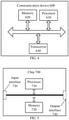
- FIG. 3 is a schematic block diagram of a terminal device 400 according to an embodiment of the present application. As shown in FIG. 3 , the terminal device 400 includes:
- FIG. 4 is a schematic structural diagram of a communication device 600 according to an embodiment of the present application.
- the communication device 600 shown in FIG. 4 includes a processor 610.
- the processor 610 can call and run a computer program from a memory to implement the methods in the embodiments of the present application.
Landscapes
- Engineering & Computer Science (AREA)
- Computer Networks & Wireless Communication (AREA)
- Signal Processing (AREA)
- Mobile Radio Communication Systems (AREA)
- Telephone Function (AREA)
Abstract
Description
- Embodiments of the present application relate to the field of communication technologies, and in particular to a wireless communication method and a terminal device.
- New Radio (NR) technologies can be applied to Internet of Things (IoT). In order to improve system performance, two optimization mechanisms are introduced: Control Plane Cellular IoT (CIOT) optimization and User Plane CIOT Optimization, and due to the introduction of the User Plane CIOT Optimization, a Radio Resource Control (RRC) state is added, that is, an idle state with suspend indication. There is also another RRC state for a terminal device, an RRC inactive state, where the RRC inactive state and the idle state with suspend indication correspond to different behaviors of the terminal device and the network device, respectively, and when the terminal device is in the above two states, RRC connection of the terminal device is suspended.
- The network device can configure the terminal device to be in the idle state with suspend indication or the RRC inactive state. In this case, the terminal device can determine which state to transfer to according to whether the User Plane CIOT Optimization is used, which may cause that the state transferred to by the terminal device is inconsistent with the state configured by the network device. That is, the state of the terminal device is inconsistent with the state that the network device understands that the terminal device should be in, which affects subsequent communications.
- The embodiments of the present application provide a wireless communication method and a terminal device, which are beneficial to ensure the consistency of the state between layers of the terminal device, thereby ensuring subsequent data transmission.
- In a first aspect, a wireless communication method is provided, which includes: sending, by a radio resource control (RRC) layer of a terminal device, indication information to a non-access stratum (NAS) of the terminal device, where the indication information includes first state indication that is used for indicating a first RRC state; and transferring, by the NAS of the terminal device according to the first state indication, the NAS of the terminal device to a first NAS state.
- In a second aspect, a terminal device is provided, which is configured to perform the method in the foregoing first aspect or any possible implementation of the first aspect. Specifically, the terminal device includes a unit for performing the method in the foregoing first aspect or any possible implementation of the first aspect.
- In a third aspect, there is provided a terminal device including a processor and a memory. The memory is used for storing a computer program, and the processor is configured to call and run the computer program stored in the memory to perform the method in the foregoing first aspect or the implementations thereof.
- In a fourth aspect, a chip is provided, which is used to implement the method in the foregoing first aspect or the implementations thereof.
- Specifically, the chip includes a processor configured to call and run a computer program from a memory, to cause a device installed with the chip to perform the method in the foregoing first aspect or the implementations thereof.
- In a fifth aspect, a computer-readable storage medium is provided for storing a computer program that causes a computer to perform the method in the foregoing first aspect or the implementations thereof.
- In a sixth aspect, a computer program product is provided, including computer program instructions that cause a computer to perform the method in the foregoing first aspect or the implementations thereof.
- In a seventh aspect, a computer program is provided, which when running on a computer, causes the computer to perform the method in the foregoing first aspect or the implementations thereof.
- Based on the above technical solutions, when the RRC layer of the terminal device needs to transfer to the first RRC state, the RRC layer of the terminal device may send first state indication to the NAS of the terminal device to indicate the first RRC state, so that the NAS layer of the terminal device can transfer to the corresponding first NAS layer state according to the first RRC state, which is beneficial to ensure the consistency of the state between the layers of the terminal device.
-
-
FIG. 1 is a schematic diagram of a architecture of a communication system according to an embodiment of the present application; -
FIG. 2 is a schematic diagram of a wireless communication method according to an embodiment of the present application. -
FIG. 3 is a schematic block diagram of a terminal device according to an embodiment of the present application. -
FIG. 4 is a schematic block diagram of a communication device according to another embodiment of the present application. -
FIG. 5 is a schematic block diagram of a chip according to an embodiment of the present application. - The technical solutions in the embodiments of the present application will be described below in connection with the drawings in the embodiments of the present application. Obviously, the described embodiments are part of the embodiments of the present application, but not all the embodiments. All other embodiments obtained by those of ordinary skill in the art based on the embodiments in the present application without creative work fall within the protection scope of the present application.
- The technical solutions of the embodiments of the present application can be applied to various communication systems, such as a Global System of Mobile communication (GSM) system, a Code Division Multiple Access (CDMA) system, a Wideband Code Division Multiple Access (WCDMA) system, a General Packet Radio Service (GPRS), a Long Term Evolution (LTE) system, a LTE Frequency Division Duplex (FDD) system, a LTE Time Division Duplex (TDD) system, a Universal Mobile Telecommunication System (UMTS), a Worldwide Interoperability for Microwave Access (WiMAX) communication system, a 5G system, etc.
- Exemplarily, a
communication system 100 applied in an embodiment of the present application is as shown inFIG. 1 . Thecommunication system 100 may include Access and Mobility Management Function (AMF) 101, Session Management Function (SMF) 102, Policy Control Function (PCF) 103, Application Function (AF) 104, User Equipment (UE) 105 (where UE may also be called a terminal device), an Access Network(AN) or Radio Access Network (RAN) 106, User Plane Function (UPF) 107, a Data Network (DN) 108, Network Slice Selection Function (NSSF) 109, Authentication Server Function (AUSF) 110, and Unified Data Management (UDM) 111. - The AMF is responsible for mobility management and is connected to the UE and the AN or RAN, the SMF is responsible for session management and is connected to the UPF or UDM, the PCF is responsible for policy control and can be connected to the SMF, AF, and AMF, and the UDM is responsible for subscription data management.
- There can be different interfaces between the devices, for example, N1 is an interface for connection between the UE and AMF, N2 is an interface for connection between the AMF and AN or RAN, N3 is an interface for connection between the AN or RAN and UPF, N4 is an interface for connection between the SMF and UPF, N5 is an interface for connection between the PCF and AF, N6 is an interface for connection between the UPF and DN, N7 is an interface for connection between the SMF and PCF, N8 is an interface for connection between the AMF and UDM, N9 is an interface in the UPF, N10 is an interface for connection between the UDM and SMF, N11 is an interface for connection between the AMF and SMF, N12 is an interface for connection between the AUSF and AMF, N13 is an interface for connection between the AUSF and UDM, N14 is an interface in the AMF, N15 is an interface between the AMF and PCF, N22 is an interface for connection between the NSSF and AMF, and a Uu interface is an interface for connection between the UE and AN or RAN.
- The
terminal device 105 in thecommunication system 100 includes, but is not limited to, a device configured to receive/send communication signals and/or an Internet of Things (IoT) device, which may be connected with another device via wired lines, such as Public Switched Telephone Networks (PSTN), Digital Subscriber Line (DSL), digital cables, and direct cable connections; and/or via another data connection/network; and/or via a wireless interface, such as cellular networks, wireless local area networks (WLAN), digital TV networks such as DVB-H networks, satellite networks, AM-FM broadcast transmitter; and/or another terminal device. A terminal device configured to perform communication through a wireless interface may be referred to as a "wireless communication terminal", a "wireless terminal" or a "mobile terminal". Examples of the mobile terminal include but are not limited to a satellite or cellular phone; a Personal Communications System (PCS) terminal that can combine cellular radio phones with data processing, fax, and data communication capabilities; a PDA that may include radio phones, pagers, Internet/intranet access, a Web browser, a memo pad, a calendar, and/or a Global Positioning System (GPS) receiver; and conventional laptop and/or palmtop receivers or other electronic devices including radio telephone transceivers. The terminal device may refer to an access terminal, user equipment (UE), a user unit, a user station, a mobile station, a mobile site, a remote station, a remote terminal, a mobile equipment, a user terminal, a terminal, wireless communication equipment, a user agent, or a user device. The access terminal may be a cellular phone, a cordless phone, a Session Initiation Protocol (SIP) phone, a wireless local loop (WLL) station, a personal digital assistant (PDA), and wireless communication functional handheld devices, computing devices or other processing devices connected to wireless modems, in-vehicle devices, wearable devices, terminal devices in 5G networks, terminal devices in the future evolution of PLMN, or the like. - Optionally, Device to Device (D2D) communication may be performed between the
terminal devices 105. - Optionally, the 5G system or 5G network may also be referred to as a New Radio (NR) system or NR network.
- It should be understood that the terms "system" and "network" are often used interchangeably herein. The term "and/or" used herein is merely to describe relative relationships of relative objects, indicating that there can be three kinds of relationships. For example, A and/or B can indicate three cases where A exists alone, A and B exist simultaneously, or B exists alone. In addition, the character "/" used herein generally indicates that the related objects before and after this character are in an "or" relationship.
- The 5G technologies can also be applied to Internet of Things (IoT), and Internet of Things devices (IoT devices) can access a 5G Network using Wide Band (WB) E-UTRAN or Narrow Band (NB) E-UTRAN.
- In order to improve system performance, two optimization mechanisms are introduced in the 5G system: Control Plane CIOT Optimization and User Plane CIOT Optimization.
- A main feature of the Control Plane CIOT Optimization lies in that data can be transmitted by using Non-Access Stratum (NAS) signaling without using the N3 tunnel between the base station and the UPF to transmit data. By transmitting a small amount of data with this method, the cumbersome N3 user plane activation and deactivation signaling transmission can be reduced.
- A main feature of the User Plane CIOT Optimization lies in that an RRC state is added, that is, an idle state with suspend indication. In addition, in the 5G system, the terminal device also has an RRC inactive state. The RRC inactive state and the idle state with suspend indication respectively correspond to different behaviors of the terminal device and the network device. For example, when the terminal device is in the idle state with suspend indication, the network device will save the context of the UE and release the N3 tunnel between the base station and the UPF, and when the terminal device is in the RRC inactive state, the network device will save the context of the UE and reserve the N3 tunnel between the base station and the UPF.
- In the 5G system, the base station can determine that the UE enters a certain RRC state, for example, the RRC inactive state or the idle state with suspend indication, and configure the RRC layer of the UE to transfer to this RRC state. Further, the RRC layer of the UE may enter the RRC state according to the network configuration, and instruct the NAS of the UE to suspend the RRC connection. When the NAS of the UE receives the indication, it can determine which state to enter according to whether the UE is currently using the User Plane CIOT Optimization or not. For example, if the User Plane CIOT Optimization is being used, it enters a 5G Mobility Management Idle state with suspend indication (5GMM-Idle with suspend indication), or if the User Plane CIOT Optimization is not used, it enters a 5G Mobility Management connected state with inactive indication (5GMM-Connected with Inactive indication).
- It can be seen that transferring of the state in the above method may cause the state of the terminal device to be inconsistent with the state of the terminal device understood by the network device. For example, if the base station configures to enter the RRC inactive state, but the User Plane CIOT Optimization is currently used, the NAS of the terminal device will enter the 5GMM-Idle state with suspend indication, resulting in inconsistency of the state between the RRC layer and the NAS of the terminal device, and the inconsistency between the current state of the terminal device and the network device's understanding of the current state of the terminal device results in misunderstanding of the signaling, which affects subsequent data transmission.
- In view of this, the embodiments of the present application provide a wireless communication method, which is beneficial to ensure the consistency of the state between the layers of the terminal device, and thus can ensure that the current state of the terminal device is consistent with understanding of the current state of the terminal device by the network device.
-
FIG. 2 is a schematic flowchart of awireless communication method 200 according to an embodiment of the present application. Themethod 200 can be performed by the terminal device in the communication system shown inFIG. 1 . As shown inFIG. 2 , themethod 200 includes the following content. - At S210, a radio resource control (RRC) layer of a terminal device sends indication information to a non-access stratum (NAS) of the terminal device, where the indication information includes first state indication that is used for indicating a first RRC state.
- At S220, the NAS of the terminal device transfers the NAS of the terminal device to a first NAS state according to the first state indication.
- In some embodiments, the first RRC state may be any RRC state such as an RRC inactive state, an RRC idle state with suspend indication, an RRC Connected state, an RRC idle state or the like. In particular, in some embodiments, the first RRC state may be the RRC idle state with suspend indication or the RRC inactive state. When the terminal device is in the first RRC state, the RRC connection of the terminal device is suspended.
- In an embodiment of the present application, the terminal device may determine to transfer to the first RRC state by itself, for example, the terminal device may determine to transfer to the first RRC state when there is no uplink data to be transmitted; or the terminal device may determine to transfer to the first RRC state based on indication from the network device. For example, the RRC layer of the terminal device may receive a first message from the network device, and the first message may include second state indication that is used to instruct the RRC layer of the terminal device to transfer to the first RRC state.
- Optionally, in some embodiments, the first message may be an RRC connection release message, or may also be other downlink RRC messages, which is not limited in the present application.
- In the case where the RRC layer of the terminal device determines to transfer to the first RRC state, the RRC layer of the terminal device may send indication information to the NAS layer of the terminal device, and the indication information may include the first state indication that is used for indicating the first RRC state, so that the NAS layer of the terminal device can transfer the NAS layer of the terminal device to the first NAS state according to the first state indication, and the RRC layer of the terminal device transfers to the first RRC state, where the first RRC state of the RRC layer corresponds to the first NAS state of the NAS, thereby ensuring consistency of the state between the layers of the terminal device, which is beneficial to ensure that the state to which the terminal device transfers is consistent with the state of the terminal device configured by the network device, thereby ensuring subsequent data transmission.
- It should be understood that in an embodiment of the application, the first RRC state of the RRC layer corresponds to the first NAS state of the NAS, that is, when the RRC layer of the terminal device is in the first RRC state and when the NAS of the terminal device is in the first NAS state, the behaviors on the corresponding access network and core network sides are consistent.
- As an example, if the first RRC state is the RRC idle state with suspend indication, the first NAS state is the idle state with suspend indication, which is also called a 5GMM-Idle state with suspend indication; when there is uplink signaling or data transmission and the RRC layer of the terminal device is in the RRC idle state with suspend indication, the RRC layer sends RRC connection setup (RRCConnectionSetup) signaling to the network device; and when in the RRC inactive state, the RRC layer sends RRC Connection Resume (RRCConnectionResume) signaling to the network device.
- As another example, if the first RRC state is the RRC inactive state, the first NAS state may be the inactive state, which is also called a 5GMM-Connected state with inactive indication.
- Optionally, in an embodiment, the indication information includes the first state indication and RRC connection suspend indication, and the RRC connection suspend indication is used for instructing the terminal device to suspend the RRC connection with the network device. The terminal device may suspend the RRC connection with the network device according to the RRC connection suspend indication. In this case, the first state indication can be understood as a cause value for suspending the RRC connection, and the cause value can be, for example, the RRC idle state with suspend indication or the RRC inactive state. That is, since the terminal device is transferred to the RRC idle state with suspend indication or the RRC inactive state, the RRC connection of the terminal device needs to be suspended.
- Optionally, as another embodiment, the indication information may only include the first state indication, and when the first RRC state indicated by the first state indication is the RRC idle state with suspend indication or the RRC inactive state, the terminal device may determine to suspend the RRC connection with the network device. In this case, the first state indication may also be considered as having a function of instructing to suspend the RRC connection.
- Optionally, the terminal device in an embodiment of the present application is a terminal device in the Internet of Things, that is, the terminal device may use the Control Plane CIOT Optimization and/or User Plane CIOT Optimization for data communication.
- The method embodiments of the present application are described in detail above with reference to
FIG. 2 , and the device embodiments of the present application are described in detail below in conjunction withFIGS. 3 to 5 . It should be understood that the device embodiments and the method embodiments correspond to each other, and for similar description, reference can be made to the method embodiments. -
FIG. 3 is a schematic block diagram of aterminal device 400 according to an embodiment of the present application. As shown inFIG. 3 , theterminal device 400 includes: - a
processing module 410 configured to send, at a radio resource control (RRC) layer, indication information to a non-access stratum (NAS) of the terminal device, where the indication information includes first state indication that is used for indicating a first RRC state; and - transfer, at the NAS, the NAS of the terminal device to a first NAS state according to the first state indication.
- Optionally, in some embodiments, if the first RRC state is an RRC idle state with suspend indication, the first NAS state is an idle state with suspend indication; or
- if the first RRC state is an RRC inactive state, the first NAS state is a connected state with inactive indication.
- Optionally, in some embodiments, the indication information further includes RRC connection suspend indication that is used for instructing the terminal device to suspend the RRC connection with the network device.
- Optionally, in some embodiments, the
terminal device 400 further includes: - a communication module 420 configured to receive, at the RRC layer, second state indication sent by the network device, where the second state indication is used for indicating the first RRC state, and
- the
processing module 410 is further configured to determine, at the RRC layer, the first state indication according to the second state indication. - Optionally, in some embodiments, the second state indication is included in an RRC connection release message.
- Optionally, in some embodiments, the
processing module 410 is further configured to: - transfer, at RRC layer, the RRC layer of the terminal device to the first RRC state according to the second state indication.
- Optionally, in some embodiments, the terminal device is a terminal device in the Internet of Things.
- Optionally, in some embodiments, the above-mentioned communication module may be a communication interface or a transceiver, or an input/output interface of a communication chip or a system-on-chip. The above-mentioned processing module may be one or more processors.
- It should be understood that the
terminal device 400 according to the embodiments of the present application can correspond to the terminal device in the method embodiments of the present application, and the above-mentioned and other operations and/or functions of the units in theterminal device 400 are used to implement the process for the terminal device inmethod 200 as shown inFIG. 2 , which will not be repeated here for the sake of brevity. -
FIG. 4 is a schematic structural diagram of acommunication device 600 according to an embodiment of the present application. Thecommunication device 600 shown inFIG. 4 includes aprocessor 610. Theprocessor 610 can call and run a computer program from a memory to implement the methods in the embodiments of the present application. - Optionally, as shown in
FIG. 4 , thecommunication device 600 can further include amemory 620. Theprocessor 610 can call and run the computer program from thememory 620 to implement the methods in the embodiments of the present application. - The
memory 620 can be a separate device independent of theprocessor 610, or can be integrated in theprocessor 610. - Optionally, as shown in
FIG. 4 , thenetwork device 600 can further include atransceiver 630, and theprocessor 610 can control thetransceiver 630 to communicate with other devices, and specifically to transmit information or data to other devices, or receive information or data transmitted from other devices. - The
transceiver 630 can include a transmitter and a receiver. Thetransceiver 630 can further include an antenna, and the number of the antennas can be one or more. - Optionally, the
communication device 600 can specifically be a network device in the embodiments of the present application, and thecommunication device 600 can carry out the corresponding processes which are implemented by the network device in the methods of the embodiments of the present application, which will not be repeated here for the sake of brevity. - Optionally, the
communication device 600 can specifically be a mobile terminal/terminal device in the embodiments of the application, and thecommunication device 600 can implement the corresponding processes which are implemented by the mobile terminal/terminal device in the methods according to the embodiments of the present application, which will not be repeated here for the sake of brevity. -
FIG. 5 is a schematic structural diagram of a chip according to an embodiment of the present application. Achip 700 shown inFIG. 5 includes aprocessor 710 which can call and run a computer program from a memory to implement the methods in the embodiments of the present application. - Optionally, as shown in
FIG. 5 , thechip 700 can further include amemory 720. Theprocessor 710 can call and run the computer program from thememory 720 to implement the methods in the embodiments of the present application. - The
memory 720 can be a separate device independent of theprocessor 710, or can be integrated in theprocessor 710. - Optionally, the
chip 700 can further include aninput interface 730. Theprocessor 710 can control theinput interface 730 to communicate with other devices or chips, and specifically, to obtain information or data transmitted by other devices or chips. - Optionally, the
chip 700 can further include anoutput interface 740. Theprocessor 710 can control theoutput interface 740 to communicate with other devices or chips, and specifically, to output information or data to other devices or chips. - Optionally, the chip can be applied to the network device in the embodiments of the present application, and the chip can carry out the corresponding processes which are implemented by the network device in the methods of the embodiments of the present application, which will not be repeated here for the sake of brevity.
- Optionally, the chip can be applied to the mobile terminal/terminal device in the embodiments of the present application, and the chip can implement the corresponding processes which are implemented by the mobile terminal/terminal device in the methods of the embodiments of the present application, which will not be repeated here for the sake of brevity.
- It should be understood that the chip mentioned in the embodiments of the present application can also be referred to as a system-level chip, a system chip, a chip system, or a system-on-chip.
- It should be understood that the processor according to the embodiments of the present application can be an integrated circuit chip with signal processing capability. In the implementations, the steps of the foregoing method embodiments can be completed by an integrated logic circuit of hardware in the processor or by instructions in a form of software. The foregoing processor can be a general-purpose processor, a Digital Signal Processor (DSP), an Application Specific Integrated Circuit (ASIC), a Field Programmable Gate Array (FPGA), other programmable logic devices, discrete gate or transistor logic device, or a discrete hardware component, which can implement the methods, steps, and logical blocks disclosed in the embodiments of the present disclosure. The general-purpose processor can be a microprocessor, any conventional processor or the like. The steps of the methods disclosed in connection with the embodiments of the present disclosure can be directly embodied in and performed by a hardware decoding processor, or can be implemented by a combination of hardware and software modules in the decoding processor. The software modules can be located in a mature storage medium in the art such as a random access memory, a flash memory, a read-only memory, a programmable read-only memory, an electrically erasable programmable memory or a register. The storage medium is located in the memory, and the processor reads information in the memory and implements the steps of the above methods in combination with the hardware thereof.
- It can be understood that the memory in the embodiments of the present application may be a volatile memory or a non-volatile memory, or may include both the volatile and non-volatile memories. The non-volatile memory can be a Read-Only Memory (ROM), a Programmable ROM (PROM), an erasable PROM (EPROM), an electrically EPROM (EEPROM) or a flash memory. The volatile memory may be a Random Access Memory (RAM), which is used as an external cache. By way of exemplary but not restrictive description, many forms of RAMs are available, such as a Static RAM (SRAM), a Dynamic RAM (DRAM), a Synchronous DRAM (SDRAM), a Double Data Rate SDRAM (DDR SDRAM), an Enhanced SDRAM (ESDRAM), a Synchlink DRAM (SLDRAM)) and a Direct Rambus RAM (DR RAM). It should be noted that the memories of the systems and methods described herein are intended to include, but are not limited to, these and any other suitable types of memories.
- It should be understood that the foregoing description of the memory is exemplary rather than limiting. For example, the memory in the embodiments of the present disclosure can also be a Static RAM (SRAM), a Dynamic RAM (DRAM), a Synchronous DRAM (SDRAM), a Double Data Rate SDRAM (DDR SDRAM), an Enhanced SDRAM (ESDRAM), a Synch-Link DRAM (SLDRAM), a Direct Rambus RAM (DR RAM), among others. That is to say, the memory in the embodiments of the present disclosure is intended to include but is not limited to those and any other suitable types of memories.
- The embodiments of the present application also provide a computer-readable storage medium for storing a computer program.
- Optionally, the computer-readable storage medium can be applied to the network device in the embodiments of the present application, and the computer program causes a computer to perform the corresponding processes which are implemented by the network device in the methods of the embodiments of the present application, which will not be repeated here for the sake of brevity.
- Optionally, the computer-readable storage medium can be applied to the mobile terminal/terminal device in the embodiments of the present application, and the computer program causes a computer to perform the corresponding processes which are implemented by the mobile terminal/terminal device in the methods of the embodiments of the present application, which will not be repeated here for the sake of brevity.
- The embodiments of the present application also provide a computer program product including computer program instructions.
- Optionally, the computer program product can be applied to the network device in the embodiments of the present application, and the computer program instructions cause a computer to perform the corresponding processes implemented by the network device in the methods according to the embodiments of the present application, which will not be repeated here for the sake of brevity.
- Optionally, the computer program product can be applied to the mobile terminal/terminal device in the embodiments of the present application, and the computer program instructions cause a computer to perform the corresponding processes which are implemented by the mobile terminal/terminal device in the methods of the embodiments of the present application, which will not be repeated here for the sake of brevity.
- The embodiments of the application also provide a computer program.
- Optionally, the computer program can be applied to the network device in the embodiments of the present application, and when running on a computer, the computer program causes the computer to perform the corresponding process implemented by the network device in the methods according to the embodiments of the present application, which will not be repeated here for the sake of brevity.
- Optionally, the computer program can be applied to the mobile terminal/terminal device in the embodiments of the present application, and when running on a computer, the computer program causes the computer to perform the corresponding processes implemented by the mobile terminal/terminal device in the methods of the embodiments of the present application, which will not be repeated here for the sake of brevity.
- Those of ordinary skill in the art can recognize that the exemplary units and algorithm steps described in connection with the embodiments disclosed herein can be implemented in electronic hardware or a combination of computer software and the electronic hardware. Whether these functions are implemented in hardware or in software depends on the specific applications of the technical solutions and design constraints. Various methods can be used by professional technicians to implement the described functions for each specific application, and such implementations should not be considered as going beyond the scope of the present application.
- Those skilled in the art can clearly understand that for convenience and conciseness of the description, for the specific operating process of the systems, devices and units described above, reference can be made to corresponding processes in the foregoing method embodiments, which will not be repeated here.
- It should be understood that the systems, devices, and methods disclosed in several embodiments of the present disclosure can be implemented in other manners. For example, the device embodiments described above are merely illustrative. For example, the division of the units is only a logical function division, and in actual implementations, there can be other division manners. For example, a plurality of units or components can be combined or integrated into another system, or some features can be ignored or not implemented. In addition, the coupling or direct coupling or communication connection shown or discussed herein can also be indirect coupling or communication connection through some interfaces, devices or units, and can be in electrical, mechanical or other forms.
- The units described as separate components may be or may not be physically separated, and the components shown as units may be or may not be physical units, that is, they may be located in one place or may be distributed on multiple network units. Some or all of the units can be selected to achieve the objectives of the solutions of the embodiments according to actual requirements.
- In addition, the functional units in the embodiments of the present disclosure can be integrated into one processing unit, or each of the units can individually exist physically, or two or more of the units can be integrated into one unit.
- If implemented in the form of software functional units and sold or used as an independent product, the functions can be stored in a computer-readable storage medium. Based on such understanding, the technical solution of the present disclosure essentially, a part thereof that contributes to the prior art, or a part of the technical solution can be embodied in the form of a software product, and the computer software product is stored in a storage medium and includes instructions which cause a computer device (which may be a personal computer, a server, a network device or the like) to perform all or part of the steps of the methods described in the embodiments of the present disclosure. The foregoing storage medium includes various medium such as a USB drive, a removable hard disk, a ROM, a RAM, a magnetic disk or an optical disc that can store program codes.
- Those described above are only specific implementations of the present application, and the protection scope of the present application is not limited thereto. Any alteration or replacement readily devised by a person skilled in the art within the technical scope disclosed in the present disclosure shall fall within the scope of the present application. Therefore, the protection scope of the present application shall be subject to the protection scope of the claims.
Claims (19)
- A wireless communication method, comprising:sending, by a radio resource control (RRC) layer of a terminal device, indication information to a non-access stratum (NAS) of the terminal device, wherein the indication information comprises first state indication that is used for indicating a first RRC state; andtransferring, by the NAS of the terminal device according to the first state indication, the NAS of the terminal device to a first NAS state.
- The method according to claim 1, wherein when the first RRC state is an RRC idle state with suspend indication, the first NAS state is an idle state with suspend indication; or
when the first RRC state is an RRC inactive state, the first NAS state is a connected state with inactive indication. - The method according to claim 1 or 2, wherein the indication information further comprises an RRC connection suspend indication that is used for instructing the terminal device to suspend RRC connection with a network device.
- The method according to any one of claims 1 to 3, further comprising:receiving, by the RRC layer of the terminal device, second state indication sent by a network device, wherein the second state indication is used for indicating the first RRC state; anddetermining, by the RRC layer of the terminal device according to the second state indication, the first state indication.
- The method according to claim 4, wherein the second state indication is comprised in an RRC connection release message.
- The method according to claim 4 or 5, further comprising:transferring, by the RRC layer of the terminal device according to the second state indication, the RRC layer of the terminal device to the first RRC state.
- The method according to any one of claims 1 to 6, wherein the terminal device is a terminal device in Internet of Things.
- A terminal device, comprising:a processing module configured to send, at a radio resource control (RRC) layer, indication information to a non-access stratum (NAS) of the terminal device, wherein the indication information comprises first state indication that is used for indicating a first RRC state; andtransfer, at the NAS, the NAS of the terminal device to a first NAS state according to the first state indication.
- The terminal device according to claim 8, wherein when the first RRC state is an RRC idle state with suspend indication, the first NAS state is an idle state with suspend indication; or
when the first RRC state is an RRC inactive state, the first NAS state is a connected state with inactive indication. - The terminal device according to claim 8 or 9, wherein the indication information further comprises RRC connection suspend indication that is used for instructing the terminal device to suspend RRC connection with a network device.
- The terminal device according to any one of claims 8 to 10, wherein the terminal device further comprises:a communication module configured to receive, at the RRC layer, second state indication sent by a network device, wherein the second state indication is used for indicating the first RRC state, andwherein the processing module is further configured to determine, at the RRC layer, the first state indication according to the second state indication.
- The terminal device according to claim 11, wherein the second state indication is comprised in an RRC connection release message.
- The terminal device according to claim 11 or 12, wherein the processing module is further configured to:transfer, at the RRC layer, the RRC layer of the terminal device to the first RRC state according to the second state indication.
- The terminal device according to any one of claims 8 to 13, wherein the terminal device is a terminal device in Internet of Things.
- A terminal device comprising a processor and a memory for storing a computer program, wherein the processor is configured to call and run the computer program stored in the memory to perform the method according to any one of claims 1 to 7.
- A chip comprising a processor configured to call and run a computer program from a memory to cause a device installed with the chip to perform the method according to any one of claims 1 to 7.
- A computer-readable storage medium for storing a computer program that causes a computer to perform the method according to any one of claims 1 to 7.
- A computer program product comprising computer program instructions that cause a computer to perform the method according to any one of claims 1 to 7.
- A computer program, wherein the computer program causes a computer to perform the method according to any one of claims 1 to 7.
Priority Applications (1)
| Application Number | Priority Date | Filing Date | Title |
|---|---|---|---|
| EP23176509.0A EP4236594B1 (en) | 2019-11-01 | 2019-11-01 | Wireless communication method, terminal device and computer-readable storage medium |
Applications Claiming Priority (1)
| Application Number | Priority Date | Filing Date | Title |
|---|---|---|---|
| PCT/CN2019/115126 WO2021082001A1 (en) | 2019-11-01 | 2019-11-01 | Radio communication method and terminal apparatus |
Related Child Applications (2)
| Application Number | Title | Priority Date | Filing Date |
|---|---|---|---|
| EP23176509.0A Division EP4236594B1 (en) | 2019-11-01 | 2019-11-01 | Wireless communication method, terminal device and computer-readable storage medium |
| EP23176509.0A Division-Into EP4236594B1 (en) | 2019-11-01 | 2019-11-01 | Wireless communication method, terminal device and computer-readable storage medium |
Publications (4)
| Publication Number | Publication Date |
|---|---|
| EP3965525A1 true EP3965525A1 (en) | 2022-03-09 |
| EP3965525A4 EP3965525A4 (en) | 2022-07-06 |
| EP3965525C0 EP3965525C0 (en) | 2023-12-27 |
| EP3965525B1 EP3965525B1 (en) | 2023-12-27 |
Family
ID=75715722
Family Applications (2)
| Application Number | Title | Priority Date | Filing Date |
|---|---|---|---|
| EP19950521.5A Active EP3965525B1 (en) | 2019-11-01 | 2019-11-01 | Wireless communication method, terminal device and computer-readable storage medium |
| EP23176509.0A Active EP4236594B1 (en) | 2019-11-01 | 2019-11-01 | Wireless communication method, terminal device and computer-readable storage medium |
Family Applications After (1)
| Application Number | Title | Priority Date | Filing Date |
|---|---|---|---|
| EP23176509.0A Active EP4236594B1 (en) | 2019-11-01 | 2019-11-01 | Wireless communication method, terminal device and computer-readable storage medium |
Country Status (9)
| Country | Link |
|---|---|
| US (1) | US12245313B2 (en) |
| EP (2) | EP3965525B1 (en) |
| JP (1) | JP7590359B2 (en) |
| KR (1) | KR20220092454A (en) |
| CN (2) | CN113709834B (en) |
| BR (1) | BR112022001099A2 (en) |
| ES (1) | ES3056545T3 (en) |
| MX (1) | MX2022000875A (en) |
| WO (1) | WO2021082001A1 (en) |
Cited By (1)
| Publication number | Priority date | Publication date | Assignee | Title |
|---|---|---|---|---|
| WO2025023146A1 (en) * | 2023-07-24 | 2025-01-30 | Nec Corporation | Method performed by access network node, method performed by user equipment, method performed by core network node, access network node, user equipment, and core network node |
Families Citing this family (2)
| Publication number | Priority date | Publication date | Assignee | Title |
|---|---|---|---|---|
| ES3056545T3 (en) | 2019-11-01 | 2026-02-23 | Guangdong Oppo Mobile Telecommunications Corp Ltd | Wireless communication method, terminal device and computer-readable storage medium |
| CN115379594B (en) * | 2022-08-22 | 2024-07-16 | 上海移芯通信科技股份有限公司 | RRC (radio resource control) link release method and system |
Family Cites Families (17)
| Publication number | Priority date | Publication date | Assignee | Title |
|---|---|---|---|---|
| EP2645803B1 (en) | 2012-03-27 | 2019-07-31 | BlackBerry Limited | Enb storing rrc configuration information at another network component |
| EP3226473B1 (en) * | 2016-04-01 | 2018-12-12 | HTC Corporation | Device and method of handling user plane evolved packet system optimization procedure |
| US20190141776A1 (en) * | 2016-04-28 | 2019-05-09 | Lg Electronics Inc. | Method and apparatus for suspending/resuming nas signaling in wireless communication system |
| US10187910B2 (en) * | 2016-05-12 | 2019-01-22 | Lg Electronics Inc. | Method and apparatus for resuming RRC connection in wireless communication system |
| US10485050B2 (en) * | 2016-09-07 | 2019-11-19 | Samsung Electronics Co., Ltd. | Methods and user equipment for managing internet protocol multimedia subsystem call over long-term evolution in single radio voice call continuity area |
| JP7085534B2 (en) * | 2016-10-30 | 2022-06-16 | エルジー エレクトロニクス インコーポレイティド | A method for determining the EMM mode in a wireless communication system, and a device for this. |
| CN108024221B (en) * | 2016-11-03 | 2019-12-20 | 电信科学技术研究院 | Paging method, base station and terminal |
| CN106658758A (en) * | 2017-02-10 | 2017-05-10 | 北京小米移动软件有限公司 | State conversion method, state keeping method and device, and user equipment |
| CN109863783B (en) * | 2017-04-28 | 2022-05-31 | Lg 电子株式会社 | Method for transmitting data according to EDT |
| US20200214070A1 (en) * | 2017-06-14 | 2020-07-02 | Samsung Electronics Co., Ltd | Method and user equipment (ue) for reconnecting rrc connection with radio access network (ran) node |
| WO2019033231A1 (en) * | 2017-08-14 | 2019-02-21 | Lenovo (Beijing) Limited | Responding to radio access network paging failures |
| WO2019098135A1 (en) * | 2017-11-15 | 2019-05-23 | 京セラ株式会社 | Cellular communication system |
| CN109936878A (en) * | 2017-12-18 | 2019-06-25 | 华为技术有限公司 | A kind of method and terminal device of triggering state recovery |
| PL3791687T3 (en) * | 2018-05-10 | 2023-12-27 | Telefonaktiebolaget Lm Ericsson (Publ) | Release cause for transition from connected state |
| US11665766B2 (en) * | 2018-10-30 | 2023-05-30 | Samsung Electronics Co., Ltd. | Method and apparatus for reducing overhead of ethernet frame in next generation mobile communication system |
| US12082286B2 (en) * | 2018-11-14 | 2024-09-03 | Nokia Technologies Oy | Apparatus, method, and computer program for connection management |
| ES3056545T3 (en) | 2019-11-01 | 2026-02-23 | Guangdong Oppo Mobile Telecommunications Corp Ltd | Wireless communication method, terminal device and computer-readable storage medium |
-
2019
- 2019-11-01 ES ES23176509T patent/ES3056545T3/en active Active
- 2019-11-01 EP EP19950521.5A patent/EP3965525B1/en active Active
- 2019-11-01 MX MX2022000875A patent/MX2022000875A/en unknown
- 2019-11-01 KR KR1020217042423A patent/KR20220092454A/en not_active Ceased
- 2019-11-01 JP JP2021577827A patent/JP7590359B2/en active Active
- 2019-11-01 CN CN202110969855.5A patent/CN113709834B/en active Active
- 2019-11-01 BR BR112022001099A patent/BR112022001099A2/en unknown
- 2019-11-01 WO PCT/CN2019/115126 patent/WO2021082001A1/en not_active Ceased
- 2019-11-01 CN CN201980087490.4A patent/CN113228815A/en active Pending
- 2019-11-01 EP EP23176509.0A patent/EP4236594B1/en active Active
-
2021
- 2021-11-19 US US17/531,255 patent/US12245313B2/en active Active
Cited By (1)
| Publication number | Priority date | Publication date | Assignee | Title |
|---|---|---|---|---|
| WO2025023146A1 (en) * | 2023-07-24 | 2025-01-30 | Nec Corporation | Method performed by access network node, method performed by user equipment, method performed by core network node, access network node, user equipment, and core network node |
Also Published As
| Publication number | Publication date |
|---|---|
| EP3965525A4 (en) | 2022-07-06 |
| ES3056545T3 (en) | 2026-02-23 |
| CN113709834A (en) | 2021-11-26 |
| BR112022001099A2 (en) | 2022-05-03 |
| EP4236594B1 (en) | 2025-10-29 |
| JP7590359B2 (en) | 2024-11-26 |
| CN113709834B (en) | 2023-04-18 |
| JP2023504959A (en) | 2023-02-08 |
| MX2022000875A (en) | 2022-02-11 |
| CN113228815A (en) | 2021-08-06 |
| KR20220092454A (en) | 2022-07-01 |
| US12245313B2 (en) | 2025-03-04 |
| EP3965525C0 (en) | 2023-12-27 |
| EP4236594A3 (en) | 2023-09-27 |
| EP3965525B1 (en) | 2023-12-27 |
| EP4236594A2 (en) | 2023-08-30 |
| US20220078878A1 (en) | 2022-03-10 |
| WO2021082001A1 (en) | 2021-05-06 |
Similar Documents
| Publication | Publication Date | Title |
|---|---|---|
| US11825322B2 (en) | Measurement control method, terminal, and non-transitory computer-readable storage medium | |
| JP7548949B2 (en) | Wireless communication method, terminal device, and network device | |
| US12245313B2 (en) | Radio communication method and terminal apparatus | |
| US12126563B2 (en) | Method for activating or updating path loss RS of SRS and device | |
| US12096373B2 (en) | Method and device for activating or updating PUSCH pathloss RS | |
| WO2019242712A1 (en) | Capability interaction method and related device | |
| JP7369768B2 (en) | Resource setting method and device, communication device | |
| WO2019237241A1 (en) | Method for transmitting downlink signal and terminal device | |
| US20220167213A1 (en) | Method and device for resource coordination | |
| KR20210082434A (en) | A method for indicating the status of PDCP duplicate data, a terminal device and a network device | |
| US20220046632A1 (en) | Communication method in d2d system, terminal device, and network device | |
| CN114222331A (en) | Data transmission method and terminal equipment | |
| CN113194551B (en) | Data copy transmission configuration method, device, chip and computer program | |
| JP7381588B2 (en) | Resource determination and setting method, device, terminal, network device | |
| WO2020043009A1 (en) | Ui display method and apparatus, and terminal device and storage medium | |
| WO2020147054A1 (en) | Indication method for data replication and transmission, terminal device, and network device | |
| US11985672B2 (en) | Data transmission method and apparatus, network device and terminal | |
| WO2020000174A1 (en) | Core network selection method and apparatus, terminal device and network device | |
| WO2020042977A1 (en) | Ui display method and apparatus, terminal device, and storage medium | |
| WO2020042976A1 (en) | Ui display method, apparatus, terminal device, and storage medium | |
| CN112585900A (en) | Data processing method, terminal equipment and storage medium |
Legal Events
| Date | Code | Title | Description |
|---|---|---|---|
| STAA | Information on the status of an ep patent application or granted ep patent |
Free format text: STATUS: THE INTERNATIONAL PUBLICATION HAS BEEN MADE |
|
| PUAI | Public reference made under article 153(3) epc to a published international application that has entered the european phase |
Free format text: ORIGINAL CODE: 0009012 |
|
| STAA | Information on the status of an ep patent application or granted ep patent |
Free format text: STATUS: REQUEST FOR EXAMINATION WAS MADE |
|
| 17P | Request for examination filed |
Effective date: 20211129 |
|
| AK | Designated contracting states |
Kind code of ref document: A1 Designated state(s): AL AT BE BG CH CY CZ DE DK EE ES FI FR GB GR HR HU IE IS IT LI LT LU LV MC MK MT NL NO PL PT RO RS SE SI SK SM TR |
|
| A4 | Supplementary search report drawn up and despatched |
Effective date: 20220607 |
|
| RIC1 | Information provided on ipc code assigned before grant |
Ipc: H04W 76/27 20180101AFI20220601BHEP |
|
| GRAP | Despatch of communication of intention to grant a patent |
Free format text: ORIGINAL CODE: EPIDOSNIGR1 |
|
| STAA | Information on the status of an ep patent application or granted ep patent |
Free format text: STATUS: GRANT OF PATENT IS INTENDED |
|
| DAV | Request for validation of the european patent (deleted) | ||
| DAX | Request for extension of the european patent (deleted) | ||
| INTG | Intention to grant announced |
Effective date: 20230130 |
|
| GRAJ | Information related to disapproval of communication of intention to grant by the applicant or resumption of examination proceedings by the epo deleted |
Free format text: ORIGINAL CODE: EPIDOSDIGR1 |
|
| STAA | Information on the status of an ep patent application or granted ep patent |
Free format text: STATUS: REQUEST FOR EXAMINATION WAS MADE |
|
| GRAP | Despatch of communication of intention to grant a patent |
Free format text: ORIGINAL CODE: EPIDOSNIGR1 |
|
| STAA | Information on the status of an ep patent application or granted ep patent |
Free format text: STATUS: GRANT OF PATENT IS INTENDED |
|
| INTC | Intention to grant announced (deleted) | ||
| INTG | Intention to grant announced |
Effective date: 20230615 |
|
| GRAS | Grant fee paid |
Free format text: ORIGINAL CODE: EPIDOSNIGR3 |
|
| GRAA | (expected) grant |
Free format text: ORIGINAL CODE: 0009210 |
|
| STAA | Information on the status of an ep patent application or granted ep patent |
Free format text: STATUS: THE PATENT HAS BEEN GRANTED |
|
| AK | Designated contracting states |
Kind code of ref document: B1 Designated state(s): AL AT BE BG CH CY CZ DE DK EE ES FI FR GB GR HR HU IE IS IT LI LT LU LV MC MK MT NL NO PL PT RO RS SE SI SK SM TR |
|
| REG | Reference to a national code |
Ref country code: GB Ref legal event code: FG4D |
|
| REG | Reference to a national code |
Ref country code: CH Ref legal event code: EP |
|
| REG | Reference to a national code |
Ref country code: DE Ref legal event code: R096 Ref document number: 602019044275 Country of ref document: DE |
|
| REG | Reference to a national code |
Ref country code: IE Ref legal event code: FG4D |
|
| U01 | Request for unitary effect filed |
Effective date: 20240119 |
|
| U07 | Unitary effect registered |
Designated state(s): AT BE BG DE DK EE FI FR IT LT LU LV MT NL PT SE SI Effective date: 20240129 |
|
| PG25 | Lapsed in a contracting state [announced via postgrant information from national office to epo] |
Ref country code: GR Free format text: LAPSE BECAUSE OF FAILURE TO SUBMIT A TRANSLATION OF THE DESCRIPTION OR TO PAY THE FEE WITHIN THE PRESCRIBED TIME-LIMIT Effective date: 20240328 |
|
| PG25 | Lapsed in a contracting state [announced via postgrant information from national office to epo] |
Ref country code: ES Free format text: LAPSE BECAUSE OF FAILURE TO SUBMIT A TRANSLATION OF THE DESCRIPTION OR TO PAY THE FEE WITHIN THE PRESCRIBED TIME-LIMIT Effective date: 20231227 |
|
| PG25 | Lapsed in a contracting state [announced via postgrant information from national office to epo] |
Ref country code: GR Free format text: LAPSE BECAUSE OF FAILURE TO SUBMIT A TRANSLATION OF THE DESCRIPTION OR TO PAY THE FEE WITHIN THE PRESCRIBED TIME-LIMIT Effective date: 20240328 Ref country code: ES Free format text: LAPSE BECAUSE OF FAILURE TO SUBMIT A TRANSLATION OF THE DESCRIPTION OR TO PAY THE FEE WITHIN THE PRESCRIBED TIME-LIMIT Effective date: 20231227 |
|
| PG25 | Lapsed in a contracting state [announced via postgrant information from national office to epo] |
Ref country code: RS Free format text: LAPSE BECAUSE OF FAILURE TO SUBMIT A TRANSLATION OF THE DESCRIPTION OR TO PAY THE FEE WITHIN THE PRESCRIBED TIME-LIMIT Effective date: 20231227 Ref country code: NO Free format text: LAPSE BECAUSE OF FAILURE TO SUBMIT A TRANSLATION OF THE DESCRIPTION OR TO PAY THE FEE WITHIN THE PRESCRIBED TIME-LIMIT Effective date: 20240327 Ref country code: HR Free format text: LAPSE BECAUSE OF FAILURE TO SUBMIT A TRANSLATION OF THE DESCRIPTION OR TO PAY THE FEE WITHIN THE PRESCRIBED TIME-LIMIT Effective date: 20231227 |
|
| PG25 | Lapsed in a contracting state [announced via postgrant information from national office to epo] |
Ref country code: IS Free format text: LAPSE BECAUSE OF FAILURE TO SUBMIT A TRANSLATION OF THE DESCRIPTION OR TO PAY THE FEE WITHIN THE PRESCRIBED TIME-LIMIT Effective date: 20240427 |
|
| PG25 | Lapsed in a contracting state [announced via postgrant information from national office to epo] |
Ref country code: CZ Free format text: LAPSE BECAUSE OF FAILURE TO SUBMIT A TRANSLATION OF THE DESCRIPTION OR TO PAY THE FEE WITHIN THE PRESCRIBED TIME-LIMIT Effective date: 20231227 |
|
| PG25 | Lapsed in a contracting state [announced via postgrant information from national office to epo] |
Ref country code: SK Free format text: LAPSE BECAUSE OF FAILURE TO SUBMIT A TRANSLATION OF THE DESCRIPTION OR TO PAY THE FEE WITHIN THE PRESCRIBED TIME-LIMIT Effective date: 20231227 |
|
| PG25 | Lapsed in a contracting state [announced via postgrant information from national office to epo] |
Ref country code: SM Free format text: LAPSE BECAUSE OF FAILURE TO SUBMIT A TRANSLATION OF THE DESCRIPTION OR TO PAY THE FEE WITHIN THE PRESCRIBED TIME-LIMIT Effective date: 20231227 Ref country code: SK Free format text: LAPSE BECAUSE OF FAILURE TO SUBMIT A TRANSLATION OF THE DESCRIPTION OR TO PAY THE FEE WITHIN THE PRESCRIBED TIME-LIMIT Effective date: 20231227 Ref country code: RO Free format text: LAPSE BECAUSE OF FAILURE TO SUBMIT A TRANSLATION OF THE DESCRIPTION OR TO PAY THE FEE WITHIN THE PRESCRIBED TIME-LIMIT Effective date: 20231227 Ref country code: IS Free format text: LAPSE BECAUSE OF FAILURE TO SUBMIT A TRANSLATION OF THE DESCRIPTION OR TO PAY THE FEE WITHIN THE PRESCRIBED TIME-LIMIT Effective date: 20240427 Ref country code: CZ Free format text: LAPSE BECAUSE OF FAILURE TO SUBMIT A TRANSLATION OF THE DESCRIPTION OR TO PAY THE FEE WITHIN THE PRESCRIBED TIME-LIMIT Effective date: 20231227 |
|
| PG25 | Lapsed in a contracting state [announced via postgrant information from national office to epo] |
Ref country code: PL Free format text: LAPSE BECAUSE OF FAILURE TO SUBMIT A TRANSLATION OF THE DESCRIPTION OR TO PAY THE FEE WITHIN THE PRESCRIBED TIME-LIMIT Effective date: 20231227 |
|
| PG25 | Lapsed in a contracting state [announced via postgrant information from national office to epo] |
Ref country code: PL Free format text: LAPSE BECAUSE OF FAILURE TO SUBMIT A TRANSLATION OF THE DESCRIPTION OR TO PAY THE FEE WITHIN THE PRESCRIBED TIME-LIMIT Effective date: 20231227 |
|
| REG | Reference to a national code |
Ref country code: DE Ref legal event code: R097 Ref document number: 602019044275 Country of ref document: DE |
|
| PLBE | No opposition filed within time limit |
Free format text: ORIGINAL CODE: 0009261 |
|
| STAA | Information on the status of an ep patent application or granted ep patent |
Free format text: STATUS: NO OPPOSITION FILED WITHIN TIME LIMIT |
|
| 26N | No opposition filed |
Effective date: 20240930 |
|
| U20 | Renewal fee for the european patent with unitary effect paid |
Year of fee payment: 6 Effective date: 20241125 |
|
| REG | Reference to a national code |
Ref country code: CH Ref legal event code: PL |
|
| PG25 | Lapsed in a contracting state [announced via postgrant information from national office to epo] |
Ref country code: MC Free format text: LAPSE BECAUSE OF FAILURE TO SUBMIT A TRANSLATION OF THE DESCRIPTION OR TO PAY THE FEE WITHIN THE PRESCRIBED TIME-LIMIT Effective date: 20231227 |
|
| REG | Reference to a national code |
Ref country code: CH Ref legal event code: PL |
|
| PG25 | Lapsed in a contracting state [announced via postgrant information from national office to epo] |
Ref country code: CH Free format text: LAPSE BECAUSE OF NON-PAYMENT OF DUE FEES Effective date: 20241130 |
|
| PG25 | Lapsed in a contracting state [announced via postgrant information from national office to epo] |
Ref country code: IE Free format text: LAPSE BECAUSE OF NON-PAYMENT OF DUE FEES Effective date: 20241101 |
|
| U20 | Renewal fee for the european patent with unitary effect paid |
Year of fee payment: 7 Effective date: 20251127 |
|
| PGFP | Annual fee paid to national office [announced via postgrant information from national office to epo] |
Ref country code: GB Payment date: 20251126 Year of fee payment: 7 |
|
| PG25 | Lapsed in a contracting state [announced via postgrant information from national office to epo] |
Ref country code: HU Free format text: LAPSE BECAUSE OF FAILURE TO SUBMIT A TRANSLATION OF THE DESCRIPTION OR TO PAY THE FEE WITHIN THE PRESCRIBED TIME-LIMIT; INVALID AB INITIO Effective date: 20191101 |
|
| PG25 | Lapsed in a contracting state [announced via postgrant information from national office to epo] |
Ref country code: CY Free format text: LAPSE BECAUSE OF FAILURE TO SUBMIT A TRANSLATION OF THE DESCRIPTION OR TO PAY THE FEE WITHIN THE PRESCRIBED TIME-LIMIT; INVALID AB INITIO Effective date: 20191101 |