EP3965408A1 - Method and communication system for a power-saving operation of a subscriber line - Google Patents
Method and communication system for a power-saving operation of a subscriber line Download PDFInfo
- Publication number
- EP3965408A1 EP3965408A1 EP20194703.3A EP20194703A EP3965408A1 EP 3965408 A1 EP3965408 A1 EP 3965408A1 EP 20194703 A EP20194703 A EP 20194703A EP 3965408 A1 EP3965408 A1 EP 3965408A1
- Authority
- EP
- European Patent Office
- Prior art keywords
- port
- interface
- network device
- access
- customer router
- Prior art date
- Legal status (The legal status is an assumption and is not a legal conclusion. Google has not performed a legal analysis and makes no representation as to the accuracy of the status listed.)
- Granted
Links
Images


Classifications
-
- H—ELECTRICITY
- H04—ELECTRIC COMMUNICATION TECHNIQUE
- H04M—TELEPHONIC COMMUNICATION
- H04M11/00—Telephonic communication systems specially adapted for combination with other electrical systems
- H04M11/06—Simultaneous speech and data transmission, e.g. telegraphic transmission over the same conductors
- H04M11/062—Simultaneous speech and data transmission, e.g. telegraphic transmission over the same conductors using different frequency bands for speech and other data
-
- H—ELECTRICITY
- H04—ELECTRIC COMMUNICATION TECHNIQUE
- H04L—TRANSMISSION OF DIGITAL INFORMATION, e.g. TELEGRAPHIC COMMUNICATION
- H04L12/00—Data switching networks
- H04L12/02—Details
- H04L12/12—Arrangements for remote connection or disconnection of substations or of equipment thereof
-
- Y—GENERAL TAGGING OF NEW TECHNOLOGICAL DEVELOPMENTS; GENERAL TAGGING OF CROSS-SECTIONAL TECHNOLOGIES SPANNING OVER SEVERAL SECTIONS OF THE IPC; TECHNICAL SUBJECTS COVERED BY FORMER USPC CROSS-REFERENCE ART COLLECTIONS [XRACs] AND DIGESTS
- Y02—TECHNOLOGIES OR APPLICATIONS FOR MITIGATION OR ADAPTATION AGAINST CLIMATE CHANGE
- Y02D—CLIMATE CHANGE MITIGATION TECHNOLOGIES IN INFORMATION AND COMMUNICATION TECHNOLOGIES [ICT], I.E. INFORMATION AND COMMUNICATION TECHNOLOGIES AIMING AT THE REDUCTION OF THEIR OWN ENERGY USE
- Y02D30/00—Reducing energy consumption in communication networks
- Y02D30/70—Reducing energy consumption in communication networks in wireless communication networks
Definitions
- the present invention is directed to a method for a power-saving operation of a subscriber line and a communication system for enabling a power-saving operation of a subscriber line, wherein the subscriber line may be an xDSL subscriber line or an optical fiber.
- Digital Subscriber Line (DSL) technology is deployed to provide digital broadband access to the Internet for example using a local telephone line.
- DSM energy-efficient dynamic spectrum management
- the method and the communication system allows a user to initiate a VoIP session to a called party or receive a VoIP call from a calling party even if the user's subscriber line is currently deactivated.
- an exemplary communication system 10 is depicted which is configured to enable a power-saving operation of at least one subscriber line, wherein the at least subscriber line may be an xDSL subscriber line or an optical fiber.
- the illustrative communication system 10 may comprise a wide-area wireless network 40, which preferably may be implemented as a low-power wide-area radio (LPWAN) network.
- the exemplary LPWAN network 40 is a type of a wireless telecommunication wide area network designed to allow long-range communications at a low bit rate and at low power.
- the illustrative LPWAN network 40 may, for example, support low-power wide-area network protocols such as LoRaWAN (LoRaWAN: Long Range Wide Area Network) developed by Semtech (see URL: https://en.wikipedia.org/wiki/LoRa).
- the LPWAN network may be based on the Narrowband Internet of Things (NB-IoT) which is a low-power wide area network radio technology standard developed by 3GPP (Third Generation Partnership Project).
- NB-IoT Narrowband Internet of Things
- the illustrative communication system 10 may comprise a network device 90, which may constitute a physical server of an Internet service provider, that may operate an own ISP network 80.
- the network device 90 may include a communication interface 91 and a wireless network interface 93 configured to communicate via the wide-area wireless network 40.
- the wireless network interface 93 is implemented as a low-power radio network interface using a low-power wide-area network protocol, e.g. the LoRaWAN network protocol. In the following, thus interface 93 may be called a LPWAN interface.
- the network device 90 may include a control unit 92, which may be implemented as a microcontroller configured to control and monitor the functions of the network device 90.
- the communication system 10 may comprise at least one customer router 20, which may be implemented as an Integrated Access Device (IAD), which may include a conventional xDSL modem.
- the customer router 20 may comprise at least a first xDSL access interface 23.1 and a wireless network interface 25, which may be implemented each as a physical and/or software component.
- Interface 25 is configured to communicate via the wide-area wireless network 40 with the network device 90.
- the wireless network interface 25 is a low-power radio network interface using a low-power wide-area network protocol, e.g. the LoRaWAN network protocol. In the following, thus interface 25 may be called a LPWAN interface.
- a LPWAN interface In the preferred embodiment as shown in Fig.
- the customer router 20 may comprise two access interfaces, namely xDSL access interface 23.1 and an xDSL access interface 23.2. It is to be noted, that alternatively the access interfaces 23.1 and 23.2 may be implemented as optical access interfaces. Furthermore, the customer router 20 may comprise a communication interface 21 configured to connect to a user end device 110.
- the user end device 110 may be a personal computer including, for example, a softphone and a Session Initiation Protocol (SIP) user agent client/server configured to establish and receive for example VoIP sessions.
- SIP Session Initiation Protocol
- the personal computer 110 may be connected via a cable to communication interface 21 of the customer router 20.
- Communication interface 21 may be implemented according to an Ethernet standard.
- the customer router 20 may comprise a Wi-Fi interface (not shown) which may be configured to communicate with a user end device via a wireless connection.
- the customer router 20 may include a control unit 26 configured to preferably control and monitor the functions of the customer router 20.
- a memory 27 may be implemented at the router 20 for storing e.g. data and/or instructions and/or application programs.
- at least one senor, e.g. a motion sensor 28 may be implemented at the customer router 20 for detecting a movement of the user.
- the exemplary communication system 10 may comprise at least one access network device 50, which may be implemented as a digital subscriber line access multiplexer (DSLAM) or an multi-service access node (MSAN).
- DSLAM digital subscriber line access multiplexer
- MSAN multi-service access node
- the access network device 50 constitutes a DSLAM
- the DSLAM 50 may comprise at least one xDSL port 51.1 and a communication interface 55 configured to communicate with the communication interface 91 of the network device 90.
- the DSLAM 50 may comprise two xDSL ports, namely the xDSL port 51.1 and and xDSL port 51.2.
- the DSLAM 50 may comprise a control unit 56 which may be implemented as a microcontroller configured to control and monitor the functions of the DSLAM 40.
- the illustrative communication system 10 may further comprise at least one xDSL subscriber line 100.1, which is terminated by the xDSL access interface 23.1 of the customer router 20 and by the first xDSL port 51.1 of the DSLAM 50.
- a second xDSL subscriber line 100.2 may be implemented which is terminated by the xDSL access interface 23.2 of the customer router 20 and by the xDSL port 51.2 of the DSLAM 50.
- the exemplary DSLAM 50 is configured to deactivate the xDSL port 51.1 and, if implemented, the xDSL port 51.2 preferably in response to a time scheduler and/or in response to a predefined event.
- a respective time scheduler maybe is stored in a memory 57 of the DSLAM 50.
- the DSLAM 50 and in particular the microcontroller 56 may be configured to detect a predefined event, which causes the access network device 50 to deactivate the xDSL port 50.1 and/or, if available, the xDSL port 51.2.
- a predefined event may be a user-based behavior such as the termination of an Internet session or a VoIP session, which may be detected by the access network device 50.
- the customer router 20 may be configured to trigger activation or reactivation of a deactivated xDSL subscriber line, e.g. the xDSL subscriber line 100.1 and/or, if implemented xDSL subscriber line 100.2., if needed by the user. This is done for example by transmitting a request message for activating xDSL port 51.1 of the access network device 50 via wireless network interface 25 to the network device 90.
- the control unit 26 is configured to cause the customer router 20 to transmit such a request message.
- the network device 90 may be configured to generate an xDSL port activating signal in response to the request message received from the customer router 20 and to transmit the xDSL port activating signal via its communication interface 91 to the access network device 50.
- the communication interfaces 55 and 91 can be connected via an electrical cable, an optical fiber or via a wireless connection.
- the control unit 56 of the access network device 50 may be configured to process and interpret the xDSL port activating signal to cause the DSLAM 50 to activate or reactivate the xDSL port 51.1 such that the xDSL subscriber line 100.1 will become available for data transmission between the customer device 20 and the access network devise 50.
- the request message transmitted by the customer router 20 may include information of the customer router 20 and/or the user and/or the xDSL interface 23.1 and/or the xDSL interface 23.2, which allows the network device 90 to generate a specific xDSL port activating signal which in turn carries information indicating to the access network device 50 which deactivated xDSL port or ports, e.g. xDSL port 51.1 and/or xDSL port 51.2 should be activated. It should be noted, that a plurality of xDSL ports 51.1 to 51.n may be implemented in the DSLAM 50 which may be associated with different customer routers.
- the preferred communication system 10 may include an IP-based communication subsystem 60, which may be implemented as the Internet Multimedia Subsystem (IMS).
- IMS Internet Multimedia Subsystem
- the Internet multimedia subsystem is described by Gerd Siegmund in the text book “technik der Netze 2", 6. Auflage, Chapter 10, 2009, Wegig Verlag .
- the customer router 20 may be configured to transmit signaling messages, for example Session Initiation Protocol (SIP) messages generated by the personal computer 110, via its LPWAN interface 25 to the IP-based communication subsystem 60.
- the IP-based communication subsystem is preferably configured to provide multimedia services like Voice over IP (VoIP).
- a physical server 70 is associated with the IP-based communication subsystem 60.
- the server 70 may provide and support IP-based multimedia services like VoIP and may comprise a wireless network interface 73 configured to receive signaling messages from the customer router 20.
- the wireless network interface 73 may be implemented as a low-power radio network interface configured to support a low-wide-area network protocol such as the LoRaWAN network protocol.
- interface 73 may be called a LPWAN interface configured to communicate via the LPWAN network 40.
- the server 70 of the IP-based communication subsystem 60 may be further configured to transmit signaling messages, for example SIP messages received for example from a calling device 120, via its wireless network interface 73 to the customer router 20, which in turn is configured to receive the signaling messages from the IP-based communication subsystem 60 and the server 70, respectively.
- Signaling messages may be exchanged between the customer router 20 and the server 70 of the IP-based communication system 60 via the LPWAN network 40 as shown in Figure 1 .
- the process of transmitting signaling messages over the LPWAN network 40 to be exchanged between the customer router 20 and the IP-based communication subsystem 60 enables the user of the personal computer 110 to initiate a VoIP session or receive a VoIP call, even if the xDSL subscriber line 100.1 is deactivated or not available at all.
- the access network device 50 may be also configured to deactivate the xDSL port 51.2 terminating the xDSL subscriber line 100.2.
- the customer router 20 is configured to transmit a request message for activating xDSL port 51.2 via its LPWAN interface 25 to the network device 90.
- the network device 90 in turn is configured to generate a port activating signal with respect to the second xDSL port 51.2 in response to the request message received from the customer router 20 and to transmit via its communication interface 91 the port activating signal with respect to the second xDSL port 51.2 to the access network device 50.
- the access network device may be configured to activate the xDSL port 50.2 and in a similar manner as described in detail with respect to the xDSL port 51.1.
- the at least one access interface 23.1 of customer router 20 may be implemented as an optical access interface which constitutes an optical network termination (ONT) of an optical fiber according to the Fiber to Home (FTTH) technology used to connect the customer device 20 to access network device 50.
- ONT optical network termination
- FTTH Fiber to Home
- the subscriber line 100.1 and, if implemented, the subscriber line 100.2 constitute each an optical fiber.
- the access network device 50 can be implemented as an MSAN device, which may comprise at least one optical port 51.1, which constitutes an optical line termination (OLT) and the communication interface 55 configured to communicate with the communication interface 91 of the network device 90.
- the MSLAN 50 may comprise two optical ports, namely optical port 51.1 and optical port 51.2.
- the MSLAN 50 may comprise the control unit 56, which may be implemented as a microcontroller configured to control and monitor the functions of the MSLAN 40.
- the optical ports 51.1 and 51.2 as well as the interfaces illustrated herein may be implemented as physical and/or software components. Therefore, the access network device 50 may be configured to deactivate the optical port 51.1 and, if available, the optical port 51.2.
- optical fiber 100.1 is terminated by the optical access interface 23.1 of the customer router 20 and by the first optical port 51.1 of the access network device 50, wherein optical fiber 100.2, if implemented, is terminated by the optical access interface 23.2 of the customer router 20 and by the optical port 51.2 of the access network device 50.
- the access network device 50 is configured to deactivate the optical port 53 terminating the optical fiber 100.1, wherein the customer router 20 is configured to transmit a request message for activing the optical port 53 of the access network device 50 via its wireless network interface 25 to the network device 90.
- the network device 90 in turn may be configured to generated an optical port activating signal in response to the request message received from the customer router 20 and to transmit, via its communication interface 91, the optical port activating signal to the access network device 50.
- the access network device 50 in turn may be configured to activate the optical port 53 terminating the optical fiber 100.1.It should be noted that an effective power-saving operation may be achieved, if all optical network terminations connected to the optical port 53 of the access network device 50 are operated in a power-saving mode. Otherwise, the power-saving effect works only on the optical access interfaces 25 of customer router 20.
- control unit 26 may be configured to detect, for example in connection with the motion sensor 28, the behavior of the user of the personal computer 110.
- the customer router 20 may comprise a wireless broadband access interface 22, which may be implemented as a cellular access interface like a LTE-based interface.
- the customer router 20 may be configured to establish for example an Internet session via the wireless broadband access interface 22 using a cellular access network 30.
- the wireless broadband access interface 22 may be used if, for example, the subscriber lines 23.1 and 23.2 are not available for communication.
- xDSL access interface 23.1 is implemented in the customer router 20
- xDSL interface 23.1 is activated and at least two xDSL ports 51.1 and 51.2 are implemented in the access network device 50.
- the xDSL interface 23.1 is connected via the xDSL subscriber line 100.1 to xDSL port 51.1 of the DSLAM 50. It is further assumed that the xDSL port 51.1 of the access network device 50 has been deactivated by the control unit 56, for example by using a time scheduler stored in memory 57. For example, the time scheduler triggers the control unit 56 to deactivate xDSL port 51.1 between 9am to 6pm. In addition or alternatively, the control unit 56 may be configured to deactivate xDSL port 51.1 if the customer router 20 is no more in operation since a predefined time interval. Therefore, a timer, which may be integrated in the control unit 56 can trigger the control unit 56 after a predetermined timeout to deactivate xDSL port 51.1.
- step 1.1 this can be initiated by entering a respective request, e.g. by entering a Unified Resource Locater (URL), on the PC 110 and transmitting it to customer router 20.
- the control unit 26 may be configured to interpret the respective request as an Internet session initiation request.
- the control unit 26 is caused at step 1.2 to generate and transmit a request message for activating the deactivated xDSL port 51.1 via its LPWAN interface 25 and the LPWAN network 40 to the LPWAN interface 93 of the network device 90 which belongs to the ISP network 80.
- the network device 90 may acknowledge receipt of the request message and generates in response to the request message received at step 1.2 an xDSL port activating signal.
- the network device 20 transmits the xDSL port activating signal generated at step 1.3 via its communication interface 91 to the communication interface 55 of the access network device 50.
- the access network device 50 is configured to activate the xDSL port 51.1. It is assumed, that the xDSL access interface 23.1 of the customer router 20 is activated or, for example, has been activated by the control unit 26 in response to the Internet session initiation request entered by the user at the PC 110.
- a DSL training procedure e.g. a supervectoring training procedure
- a DSL training procedure may be started in a known manner between the customer router 20 and the access network device 50.
- the xDSL subscriber line 100.1 is available for data transmission and for example a Real Time Protocol (RTP) data traffic session can be established at step 1.6 using the xDSL subscriber line 100.1.
- RTP Real Time Protocol
- the DSLAM 50 may be configured to inform the IMS 60 and the server 70, respectively, of the fact, that xDSL subscriber line 100.1 is now available for data transmission.
- the server 70 may be configured to control transmission of data and/or signaling messages destined for the PC 110 via its communication interface 71 to communication interface 54 of the DSLAM 50, which in turn may forward the data and/or signaling messages to the customer router 20 using the xDSL subscriber line 100.1.
- step 1.2 i.e. generating and transmitting a request message for activating the deactivated xDSL port 51.1, may be triggered if the customer router 20 and in particular the motion sensor 28 detects a motion of the user.
- the control unit 26 may be configured to generate and transmit a respective request message for activating the deactivating xDSL port 51.1 in response to a respective output of the motion sensor 28, which may be electrically connected to the control unit 26.
- the xDSL access interface 23.1 of the customer router 20 can stay activated all the time or deactivated in response to a time scheduler stored for example in memory 27 of the customer router 20 or in response to at least one predefined event which may be a predetermined signal entered by the user on the PC 110 or automatically generated by the PC 110, indicating for example the termination of a session.
- the user of the PC 110 wants to establish a VoIP session to the SIP capable end device 120 using the known SIP protocol as mentioned above while the xDSL port 51.1 is currently deactivated.
- DSLAM 50 and/or customer router 20 are configured to inform the IP-based communication subsystem 60 and the server 70, respectively, that xDSL port 51.1 associated with xDSL subscriber line 100.1 is currently deactivated so that signaling messages have to be exchanged between the customer router 20 and the server 70 using the LPWAN network 40 instead of the xDSL subscriber line 100.1.
- the user may enter a respective request on the PC 110 which in turn generates in response to the request a respective invite message which is forwarded to the router 20.
- the control unit 26 is configured to cause the customer router 20 to transmit, at step 2.2, the invite message via its LPWAN interface 25 and the LPWAN network 40 to the IP-based communication subsystem 60 and the server 70, respectively.
- the server 70 may function as a SIP server configured to forward the invite message to the end device 120 in a known manner.
- the customer router 20 generates in response the invite message received from PC 110 a request message for activating the deactivated xDSL port 51.1 of the access network device 50 and transmits the request message via its LPWAN interface 25 over the LPWAN network 40 to the LPWAN interface 93 of the network device 90.
- the IP-based communication subsystem 60 and in particular the server 70 may transmit, at step 2.4, a 180 ringing message via the LPWAN network 40 to the LPWAN interface 25 of the customer router 20.
- the network device 90 generates an xDSL port activating signal in response to the request message received from the customer router 20 and transmits it to the access network device 50.
- the access network device 50 activates in response to the received xDSL port activating signal its xDSL port 51.1.
- an xDSL training procedure may be executed between customer router 20 and access network device 50 at step 2.6.
- the xDSL training is finished at step 2.7 the xDSL subscriber line 100.1 is available for data transmission between the customer router 20 and the DSLAM 50.
- a 200 OK message generated by end device 120 can be transmitted via the server 70 using its communication interface 71 to communication interface 54 of the DSLAM 50 and further via the xDSL subscriber line 100.1 and the customer router 20 to the PC 110.
- an ACK (Acknowledge) message may be transmitted from the PC 110 via customer router 20, xDSL subscriber line 100.1 and server 70 to the end device 120.
- a Real Time Protocol (RTP) data traffic session can be established using the xDSL subscriber line 100.1.
- RTP Real Time Protocol
- the DSLAM 50 may be configured to inform the IMS 60 and the server 70, respectively, of the fact, that xDSL subscriber line 100.1 is now available for data transmission.
- the server 70 may be configured to control transmission of data and/or signaling messages destined for the PC 110 via its communication interface 71 to communication interface 54 of the DSLAM 50, which in turn may forward the data and/or signaling messages to the customer router 20 using the xDSL subscriber line 100.1.
- a Bye message is transmitted, at step 2.11, from the PC 110 over customer router 20, xDSL subscriber line 100.1, DSLAM 50, server 70 and further to end device 120.
- a 200 OK message is transmitted from end device 120 via server 70, DSLAM 50, xDSL subscriber line 100.1, customer router 20 to PC 110.
- end device 120 will initiate a VoIP session to the user of PC 110, while xDSL subscriber line 100.1 and xDSL port 51.1, respectively, is currently deactivated. It is further assumed, that DSLAM 50 and/or customer router 20 are configured to inform the IP-based communication subsystem 60 and the server 70, respectively, that xDSL port 51.1 associated with xDSL subscriber line 100.1 is currently deactivated so that signaling messages have to be exchanged between the customer router 20 and the server 70 using the LPWAN network 40 instead of the xDSL subscriber line 100.1.
- the user may now enter, for example, the calling number of the user of PC 110 on its end device 120.
- end device 120 generates at step 3.2 an invite message and transmit it to the server 70, which in turn forwards the invite message via the LPWAN interface 73 and the LPWAN network 40 to the customer router 40 and further to PC 110.
- the customer router 20 generates in response the invite message received from end device 120 a request message for activating the deactivated xDSL port 51.1 of the access network device 50 and transmits the request message via its LPWAN interface 25 over the LPWAN network 40 to the LPWAN interface 93 of the network device 90.
- a 180 ringing message may be transmitted from end device 120 via server 60, LPWAN network 40 to customer router 20 and further to PC 110.
- the network device 90 generates an xDSL port activating signal in response to the request message received at step 3.3 from the customer router 20 and transmits it at step 3.5 to the access network device 50.
- the access network device 50 activates in response to the received xDSL port activating signal its xDSL port 51.1.
- an xDSL training procedure may be executed between customer router 20 and access network device 50 at step 3.6. Once the xDSL training is finished the xDSL subscriber line 100.1 is available at step 3.7 for data transmission between the customer router 20 and the DSLAM 50.
- a Real Time Protocol (RTP) data traffic session can now be established using the xDSL subscriber line 100.1.
- the DSLAM 50 may be configured to inform the IMS 60 and the server 70, respectively, of the fact, that xDSL subscriber line 100.1 is now available for data transmission.
- the server 70 may be configured to control transmission of RTP data traffic and/or signaling messages destined for the PC 110 via its communication interface 71 to communication interface 54 of the DSLAM 50, which in turn may forward the RTP data traffic and/or signaling messages to the customer router 20 using the xDSL subscriber line 100.1.
- a 200 OK message generated by PC 110 can be transmitted via customer router 20, activated xDSL subscriber line 100.1, DSLAM 50, server 70 to end device 120.
- RTP Real time Transmission Protocol
- a Bye message is transmitted, at step 3.10, from the PC 110 over customer router 20, xDSL subscriber line 100.1, DSLAM 50, server 70 to end device 120.
- a 200 OK message is transmitted from end device 120 via server 70, DSLAM 50, xDSL subscriber line 100.1, customer router 20 to PC 110.
- a method for a power-saving operation of a subscriber line 100.1 terminated by an access interface 23.1 implemented in a customer router 20 and by a port 51.1 implemented in an access network device 50 is provided.
- the customer router 20 may further comprise a wireless network interface 25 configured to communicate via a wide-area wireless network 40 with a network device 90 using a wireless network protocol.
- the method may comprise the steps of:
- the wide-area wireless network 40 is a low-power wide-area radio network (LPWAN) and the wireless network interface 25 of the customer router 20 is a low-power radio network interface configured to communicate via the low-power wide-area radio network (LPWAN) 40 using a low-power wide-area network protocol, e.g. based on LoRaWAN or NB-IoT.
- LPWAN low-power wide-area radio network
- a low-power wide-area network protocol e.g. based on LoRaWAN or NB-IoT.
- port 51.1 is implemented as an xDSL port
- access interface 23.1 is implemented as an xDSL access interface
- subscriber line is an xDSL subscriber line.
- port 51.1 is implemented as an optical (OLT) port
- access interface 23.1 is implemented as an optical access interface (ONT)
- subscriber line is an optical fiber.
- step a) may comprise the step of deactivating the port 51.1 of the access network device 50 in response to a time scheduler and/or in response to a predefined event, e.g. a user-based behavior such as terminating a session.
- a predefined event e.g. a user-based behavior such as terminating a session.
- step a) may comprise the step of deactivating the access interface 23.1 of the customer router 20, and wherein step b) may further comprise the step b4) of activating the access interface 23.1 of the customer router 20.
- the method may further comprise the step of transmitting signaling messages via the wireless network interface 25 of the customer router 20 and the to an IP-based communication subsystem 60, e.g. an IMS (Internet Multimedia Subsystem)-based communication system, which provides multimedia services, and/or receiving, at the wireless network interface 25 of the customer router 20, signaling messages from the IP-based communication subsystem 60, wherein the signaling messages may be Session Initiation Protocol (SIP) messages.
- SIP Session Initiation Protocol
- the signaling messages may be used to initiate an IP-based session via the low-power wide-area radio network (LPWAN) 40 even if the subscriber line 100.1 is not yet activated.
- LPWAN low-power wide-area radio network
- step b1) may comprise the step of transmitting the request message in response to a time scheduler and/or in response to a predefined event.
- the event may be a movement of a user detected by the customer router 20 or an SIP-based invite request message.
- step b1) may comprise the step of transmitting the request message in response to a signaling message transmitted via the wireless network interface 25 of the customer router 20 to the IP-based communication subsystem 60 and a server 70, respectively, or in response to a signaling message received, at the wireless network interface 25 of the customer router 20, from the IP-based communication subsystem 60 and server 70, respectively.
- a communication system 10 for enabling a power-saving operation of an subscriber line 100.1.
- the system 10 may comprise:
- the wireless network interface 25 of the customer router 20 and the wireless network interface 93 of the network device 90 are each a low-power radio network interface using a low-power wide-area network protocol, and wherein the wide-area wireless network 40 is a low-power wide-area radio (LPWAN) network, e.g. based on the LoRaWAN or NB-IoT technology.
- LPWAN low-power wide-area radio
- first port 51.1 may be implemented as an xDSL port
- first access interface 23.1 is implemented as an xDSL access interface
- first subscriber line 100.1 is an xDSL subscriber line.
- first port 51.1 may be implemented as an optical port (OLT)
- first access interface 23.1 is implemented as an optical access interface (ONT)
- first subscriber line is an optical fiber.
- the customer router 20 may be configured to transmit signaling messages via its wireless network interface 25 to an IP-based communication subsystem 60 and a server 70, respectively, configured to provide multimedia services, the IP-based communication system 60 and server 70, respectively, having a wireless network interface 73 configured to receive signaling messages from the customer router 20, wherein the IP-based communication subsystem 60 and the server 70, respectively, is further configured to transmit signaling messages via its wireless network interface 73 to the customer router 20, which is configured to receive the signaling messages from the IP-based communication subsystem 60 and server 70, respectively, wherein the signaling messages may be Session Initiation Protocol (SIP) messages.
- SIP Session Initiation Protocol
- the communication system 10 may comprise a second subscriber line 100.2, wherein the customer router 20 may comprise a second access interface 23.2, wherein the access network device 50 may comprise a second port 51.2, wherein the second subscriber line 100.2 is terminated by the second access interface 23.2 of the customer router 20 and by the second port 51.2 of the access network device 50, wherein the access network device 50 may be configured to deactivate the second port 51.2 terminating the second subscriber line 100.2, wherein the customer router 20 may be configured to transmit a request message for activing the second port 51.2 of the access network device 50 via its wireless network interface 25 to the network device90, wherein the network device 90 may be configured to generated a port activating signal with respect to the second port 51.2 in response to the request message received from the customer router 20 and to transmit, via its communication interface 91, the port activating signal with respect to the second port 51.2 to the access network device 50, and wherein the access network device 50 may be configured to activate the second port 51.2 terminating the second subscriber line 100.2.
- second port 51.2 may be implemented as an xDSL port
- second access interface 23.2 is implemented as an xDSL access interface
- second subscriber line 100.2 is an xDSL subscriber line.
- second port 51.1 may be implemented as an optical port (OLT)
- second access interface 23.1 is implemented as an optical access interface (ONT)
- second subscriber line is an optical fiber.
- the access network device 50 may be configured to deactivate the first and/or second optical port 51.1 and 51.2 terminating the optical fiber 100.1 and 100.2, respectively, wherein the customer router 20 may be configured to transmit a request message for activing the optical port 51.1 and/or 51.2 of the access network device 50 via its wireless network interface 25 to the network device 90, wherein the network device 90 may be configured to generated an optical port activating signal in response to the request message received from the customer router 20 and to transmit, via its communication interface 91, the optical port activating signal to the access network device 50, and wherein the access network device 50 may be configured to activate the optical port 51.1 and/or 51.2.
- the customer router 20 may be configured to deactivate and to activate the first and/or the second access interface 23.1, 23.2 in particular in response to a time scheduler and/or at least one predefined event.
- the customer router 20 may comprise a wireless broadband access interface 22, e.g. a cellular radio access interface, and wherein the customer router 20 may be configured to establish, maintain and/or terminate an Internet session via the wireless broadband access interface 22.
- a wireless broadband access interface 22 e.g. a cellular radio access interface
- the customer router 20 may be an integrated access device (IAD) and wherein the access network device 50 may be a digital subscriber line access multiplexer (xDSLAM) or a multi-service access node (MSAN).
- IAD integrated access device
- xDSLAM digital subscriber line access multiplexer
- MSAN multi-service access node
Landscapes
- Engineering & Computer Science (AREA)
- Computer Networks & Wireless Communication (AREA)
- Signal Processing (AREA)
- Mobile Radio Communication Systems (AREA)
Abstract
Description
- The present invention is directed to a method for a power-saving operation of a subscriber line and a communication system for enabling a power-saving operation of a subscriber line, wherein the subscriber line may be an xDSL subscriber line or an optical fiber.
- Digital Subscriber Line (DSL) technology is deployed to provide digital broadband access to the Internet for example using a local telephone line.
- In order to reduce the total power of xDSL connections an energy-efficient dynamic spectrum management (DSM), called green DSL, has been developed. The power reduction is achieved by adjusting the data rate to a minimum with the drawback that, for example, VoIP calls may be conducted only with poor quality.
- It is an object of the present invention to provide a method and a communication system, which enable a power-saving operation of a subscriber line without decreasing the Quality of Service. According to a further aspect the method and the communication system allows a user to initiate a VoIP session to a called party or receive a VoIP call from a calling party even if the user's subscriber line is currently deactivated.
- The technical problem mentioned above is solved by the steps of method claim 1 and by the features of the communication system according to claim 9.
- Preferred embodiments are set forth in the dependent claims.
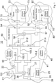
- The invention is described below by way of example in connection with the accompanying drawings, wherein:
- Figure 1
- shows an exemplary communication system, in which the invention is implemented,
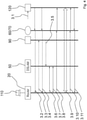
- Figure 2
- shows a flow diagram illustrating the process of activating a deactivated DSLAM in case of a user's Internet desire,
- Figure 3
- shows a flow diagram illustrating the process of initiating a VoIP session at the user end device if the user's xDSL subscriber line is still deactivated, and
- Figure 4
- shows a flow diagram illustrating a process of calling a user if the user's xDSL subscriber line is still deactivated.
- Referring now to
Figure 1 , anexemplary communication system 10 is depicted which is configured to enable a power-saving operation of at least one subscriber line, wherein the at least subscriber line may be an xDSL subscriber line or an optical fiber. - The
illustrative communication system 10 may comprise a wide-areawireless network 40, which preferably may be implemented as a low-power wide-area radio (LPWAN) network. The exemplary LPWANnetwork 40 is a type of a wireless telecommunication wide area network designed to allow long-range communications at a low bit rate and at low power. The illustrative LPWANnetwork 40 may, for example, support low-power wide-area network protocols such as LoRaWAN (LoRaWAN: Long Range Wide Area Network) developed by Semtech (see URL: https://en.wikipedia.org/wiki/LoRa). Alternatively, the LPWAN network may be based on the Narrowband Internet of Things (NB-IoT) which is a low-power wide area network radio technology standard developed by 3GPP (Third Generation Partnership Project). - Moreover, the
illustrative communication system 10 may comprise anetwork device 90, which may constitute a physical server of an Internet service provider, that may operate anown ISP network 80. Thenetwork device 90 may include acommunication interface 91 and awireless network interface 93 configured to communicate via the wide-areawireless network 40. In the exemplary embodiment, thewireless network interface 93 is implemented as a low-power radio network interface using a low-power wide-area network protocol, e.g. the LoRaWAN network protocol. In the following, thusinterface 93 may be called a LPWAN interface. In addition, thenetwork device 90 may include acontrol unit 92, which may be implemented as a microcontroller configured to control and monitor the functions of thenetwork device 90. - Furthermore, the
communication system 10 may comprise at least onecustomer router 20, which may be implemented as an Integrated Access Device (IAD), which may include a conventional xDSL modem. Thecustomer router 20 may comprise at least a first xDSL access interface 23.1 and awireless network interface 25, which may be implemented each as a physical and/or software component.Interface 25 is configured to communicate via the wide-areawireless network 40 with thenetwork device 90. In the preferred embodiment, thewireless network interface 25 is a low-power radio network interface using a low-power wide-area network protocol, e.g. the LoRaWAN network protocol. In the following, thusinterface 25 may be called a LPWAN interface. In the preferred embodiment as shown inFig. 1 thecustomer router 20 may comprise two access interfaces, namely xDSL access interface 23.1 and an xDSL access interface 23.2. It is to be noted, that alternatively the access interfaces 23.1 and 23.2 may be implemented as optical access interfaces. Furthermore, thecustomer router 20 may comprise acommunication interface 21 configured to connect to auser end device 110. Theuser end device 110 may be a personal computer including, for example, a softphone and a Session Initiation Protocol (SIP) user agent client/server configured to establish and receive for example VoIP sessions. For example, the SIP is described by Gerd Siegmund in the text book "Technik der Netze 2", 6. Auflage, Chapter 8, 2009, Hüthig Verlag. Thepersonal computer 110 may be connected via a cable tocommunication interface 21 of thecustomer router 20.Communication interface 21 may be implemented according to an Ethernet standard. In addition tocommunication interface 21 or alternatively, thecustomer router 20 may comprise a Wi-Fi interface (not shown) which may be configured to communicate with a user end device via a wireless connection. - Moreover, the
customer router 20 may include acontrol unit 26 configured to preferably control and monitor the functions of thecustomer router 20. Amemory 27 may be implemented at therouter 20 for storing e.g. data and/or instructions and/or application programs. In addition, at least one senor, e.g. amotion sensor 28 may be implemented at thecustomer router 20 for detecting a movement of the user. - In addition, the
exemplary communication system 10 may comprise at least oneaccess network device 50, which may be implemented as a digital subscriber line access multiplexer (DSLAM) or an multi-service access node (MSAN). In the preferred embodiment, it is assumed, that theaccess network device 50 constitutes a DSLAM TheDSLAM 50 may comprise at least one xDSL port 51.1 and acommunication interface 55 configured to communicate with thecommunication interface 91 of thenetwork device 90. In the preferred embodiment, theDSLAM 50 may comprise two xDSL ports, namely the xDSL port 51.1 and and xDSL port 51.2. In addition, the DSLAM 50 may comprise acontrol unit 56 which may be implemented as a microcontroller configured to control and monitor the functions of the DSLAM 40. It should be noted, that the xDSL ports 51.1 and 51.2 as well as the interfaces illustrated herein may be implemented as physical and/or software components.
Theillustrative communication system 10 may further comprise at least one xDSL subscriber line 100.1, which is terminated by the xDSL access interface 23.1 of thecustomer router 20 and by the first xDSL port 51.1 of theDSLAM 50. In the preferred embodiment, a second xDSL subscriber line 100.2 may be implemented which is terminated by the xDSL access interface 23.2 of thecustomer router 20 and by the xDSL port 51.2 of the DSLAM 50. - The exemplary DSLAM 50 is configured to deactivate the xDSL port 51.1 and, if implemented, the xDSL port 51.2 preferably in response to a time scheduler and/or in response to a predefined event. A respective time scheduler maybe is stored in a
memory 57 of theDSLAM 50. For example, the DSLAM 50 and in particular themicrocontroller 56 may be configured to detect a predefined event, which causes theaccess network device 50 to deactivate the xDSL port 50.1 and/or, if available, the xDSL port 51.2. Such a predefined event may be a user-based behavior such as the termination of an Internet session or a VoIP session, which may be detected by theaccess network device 50. - The
customer router 20 may be configured to trigger activation or reactivation of a deactivated xDSL subscriber line, e.g. the xDSL subscriber line 100.1 and/or, if implemented xDSL subscriber line 100.2., if needed by the user. This is done for example by transmitting a request message for activating xDSL port 51.1 of theaccess network device 50 viawireless network interface 25 to thenetwork device 90. In particular, thecontrol unit 26 is configured to cause thecustomer router 20 to transmit such a request message. In addition, thenetwork device 90 may be configured to generate an xDSL port activating signal in response to the request message received from thecustomer router 20 and to transmit the xDSL port activating signal via itscommunication interface 91 to theaccess network device 50. Thecommunication interfaces - The
control unit 56 of theaccess network device 50 may be configured to process and interpret the xDSL port activating signal to cause theDSLAM 50 to activate or reactivate the xDSL port 51.1 such that the xDSL subscriber line 100.1 will become available for data transmission between thecustomer device 20 and the access network devise 50. - In a preferred embodiment, the request message transmitted by the
customer router 20 may include information of thecustomer router 20 and/or the user and/or the xDSL interface 23.1 and/or the xDSL interface 23.2, which allows thenetwork device 90 to generate a specific xDSL port activating signal which in turn carries information indicating to theaccess network device 50 which deactivated xDSL port or ports, e.g. xDSL port 51.1 and/or xDSL port 51.2 should be activated. It should be noted, that a plurality of xDSL ports 51.1 to 51.n may be implemented in theDSLAM 50 which may be associated with different customer routers. - In addition, the
preferred communication system 10 may include an IP-basedcommunication subsystem 60, which may be implemented as the Internet Multimedia Subsystem (IMS). For example, the Internet multimedia subsystem is described by Gerd Siegmund in the text book "Technik der Netze 2", 6. Auflage, . - In a preferred embodiment, the
customer router 20 may be configured to transmit signaling messages, for example Session Initiation Protocol (SIP) messages generated by thepersonal computer 110, via itsLPWAN interface 25 to the IP-basedcommunication subsystem 60. The IP-based communication subsystem is preferably configured to provide multimedia services like Voice over IP (VoIP). In the preferred embodiment, aphysical server 70 is associated with the IP-basedcommunication subsystem 60. Theserver 70 may provide and support IP-based multimedia services like VoIP and may comprise awireless network interface 73 configured to receive signaling messages from thecustomer router 20. In the preferred embodiment, thewireless network interface 73 may be implemented as a low-power radio network interface configured to support a low-wide-area network protocol such as the LoRaWAN network protocol. Therefore,interface 73 may be called a LPWAN interface configured to communicate via theLPWAN network 40. Theserver 70 of the IP-basedcommunication subsystem 60 may be further configured to transmit signaling messages, for example SIP messages received for example from acalling device 120, via itswireless network interface 73 to thecustomer router 20, which in turn is configured to receive the signaling messages from the IP-basedcommunication subsystem 60 and theserver 70, respectively. With other words: Signaling messages may be exchanged between thecustomer router 20 and theserver 70 of the IP-basedcommunication system 60 via theLPWAN network 40 as shown inFigure 1 . It should be noted, that the process of transmitting signaling messages over theLPWAN network 40 to be exchanged between thecustomer router 20 and the IP-basedcommunication subsystem 60 enables the user of thepersonal computer 110 to initiate a VoIP session or receive a VoIP call, even if the xDSL subscriber line 100.1 is deactivated or not available at all. - As mentioned above, the
access network device 50 may be also configured to deactivate the xDSL port 51.2 terminating the xDSL subscriber line 100.2. Furthermore, thecustomer router 20 is configured to transmit a request message for activating xDSL port 51.2 via itsLPWAN interface 25 to thenetwork device 90. Thenetwork device 90 in turn is configured to generate a port activating signal with respect to the second xDSL port 51.2 in response to the request message received from thecustomer router 20 and to transmit via itscommunication interface 91 the port activating signal with respect to the second xDSL port 51.2 to theaccess network device 50. Now the access network device may be configured to activate the xDSL port 50.2 and in a similar manner as described in detail with respect to the xDSL port 51.1. - In an alternative preferred embodiment of the
communication system 10, the at least one access interface 23.1 ofcustomer router 20 may be implemented as an optical access interface which constitutes an optical network termination (ONT) of an optical fiber according to the Fiber to Home (FTTH) technology used to connect thecustomer device 20 to accessnetwork device 50. In this embodiment, the subscriber line 100.1 and, if implemented, the subscriber line 100.2 constitute each an optical fiber. - Therefore, the
access network device 50 can be implemented as an MSAN device, which may comprise at least one optical port 51.1, which constitutes an optical line termination (OLT) and thecommunication interface 55 configured to communicate with thecommunication interface 91 of thenetwork device 90. In a preferred embodiment, theMSLAN 50 may comprise two optical ports, namely optical port 51.1 and optical port 51.2. In addition, theMSLAN 50 may comprise thecontrol unit 56, which may be implemented as a microcontroller configured to control and monitor the functions of theMSLAN 40. It should be noted, that the optical ports 51.1 and 51.2 as well as the interfaces illustrated herein may be implemented as physical and/or software components. Therefore, theaccess network device 50 may be configured to deactivate the optical port 51.1 and, if available, the optical port 51.2. In the alternativeexemplary communication system 10 optical fiber 100.1 is terminated by the optical access interface 23.1 of thecustomer router 20 and by the first optical port 51.1 of theaccess network device 50, wherein optical fiber 100.2, if implemented, is terminated by the optical access interface 23.2 of thecustomer router 20 and by the optical port 51.2 of theaccess network device 50. - In this exemplary embodiment, the
access network device 50 is configured to deactivate the optical port 53 terminating the optical fiber 100.1, wherein thecustomer router 20 is configured to transmit a request message for activing the optical port 53 of theaccess network device 50 via itswireless network interface 25 to thenetwork device 90. Thenetwork device 90 in turn may be configured to generated an optical port activating signal in response to the request message received from thecustomer router 20 and to transmit, via itscommunication interface 91, the optical port activating signal to theaccess network device 50. Theaccess network device 50 in turn may be configured to activate the optical port 53 terminating the optical fiber 100.1.It should be noted that an effective power-saving operation may be achieved, if all optical network terminations connected to the optical port 53 of theaccess network device 50 are operated in a power-saving mode. Otherwise, the power-saving effect works only on the optical access interfaces 25 ofcustomer router 20. - It should be noted, that the
customer router 20 may be configured to deactivate and to activate the access interface 23.1 and 23.2. In particular,control unit 26 may be configured to detect, for example in connection with themotion sensor 28, the behavior of the user of thepersonal computer 110. - Moreover, the
customer router 20 may comprise a wirelessbroadband access interface 22, which may be implemented as a cellular access interface like a LTE-based interface. In this case, thecustomer router 20 may be configured to establish for example an Internet session via the wirelessbroadband access interface 22 using acellular access network 30. It should be noted that the wirelessbroadband access interface 22 may be used if, for example, the subscriber lines 23.1 and 23.2 are not available for communication. - Now the operation of the
exemplary communication system 10 is illustrated with respect to different scenarios shown in theFigures 2 to 4 . - It should be noted, that the operation of the
customer router 20 and theaccess network device 50 and thus the operation ofcommunication system 10, as illustrated below, is independent of the implementation of - i) the access interfaces 23.1 and 23.2 as xDSL access interfaces or optical interfaces,
- ii) the subscriber lines 100.1 and 100.2 as xDSL subscriber lines or optical fibers, and
- iii) the ports 51.1 and 51.2 as xDSL ports or optical ports.
- For the sake of better understanding and an easier illustration it is assumed with respect to all scenarios illustrated that only the xDSL access interface 23.1 is implemented in the
customer router 20, xDSL interface 23.1 is activated and at least two xDSL ports 51.1 and 51.2 are implemented in theaccess network device 50. - The xDSL interface 23.1 is connected via the xDSL subscriber line 100.1 to xDSL port 51.1 of the
DSLAM 50. It is further assumed that the xDSL port 51.1 of theaccess network device 50 has been deactivated by thecontrol unit 56, for example by using a time scheduler stored inmemory 57. For example, the time scheduler triggers thecontrol unit 56 to deactivate xDSL port 51.1 between 9am to 6pm. In addition or alternatively, thecontrol unit 56 may be configured to deactivate xDSL port 51.1 if thecustomer router 20 is no more in operation since a predefined time interval. Therefore, a timer, which may be integrated in thecontrol unit 56 can trigger thecontrol unit 56 after a predetermined timeout to deactivate xDSL port 51.1. - Now, it is assumed, that the user of
PC 110 wishes to get access to the Internet. At step 1.1, this can be initiated by entering a respective request, e.g. by entering a Unified Resource Locater (URL), on thePC 110 and transmitting it tocustomer router 20. Thecontrol unit 26 may be configured to interpret the respective request as an Internet session initiation request. In response to that interpretation thecontrol unit 26 is caused at step 1.2 to generate and transmit a request message for activating the deactivated xDSL port 51.1 via itsLPWAN interface 25 and theLPWAN network 40 to theLPWAN interface 93 of thenetwork device 90 which belongs to theISP network 80. At step 1.3, thenetwork device 90 may acknowledge receipt of the request message and generates in response to the request message received at step 1.2 an xDSL port activating signal. At step 1.4, thenetwork device 20 transmits the xDSL port activating signal generated at step 1.3 via itscommunication interface 91 to thecommunication interface 55 of theaccess network device 50. In response to the xDSL port activating signal theaccess network device 50 is configured to activate the xDSL port 51.1. It is assumed, that the xDSL access interface 23.1 of thecustomer router 20 is activated or, for example, has been activated by thecontrol unit 26 in response to the Internet session initiation request entered by the user at thePC 110. - At step 1.5, a DSL training procedure, e.g. a supervectoring training procedure, may be started in a known manner between the
customer router 20 and theaccess network device 50. Once the DSL training is finished the xDSL subscriber line 100.1 is available for data transmission and for example a Real Time Protocol (RTP) data traffic session can be established at step 1.6 using the xDSL subscriber line 100.1. It should be noted, that theDSLAM 50 may be configured to inform theIMS 60 and theserver 70, respectively, of the fact, that xDSL subscriber line 100.1 is now available for data transmission. Theserver 70 may be configured to control transmission of data and/or signaling messages destined for thePC 110 via its communication interface 71 tocommunication interface 54 of theDSLAM 50, which in turn may forward the data and/or signaling messages to thecustomer router 20 using the xDSL subscriber line 100.1. - It should be noted that step 1.2, i.e. generating and transmitting a request message for activating the deactivated xDSL port 51.1, may be triggered if the
customer router 20 and in particular themotion sensor 28 detects a motion of the user. As a result, thecontrol unit 26 may be configured to generate and transmit a respective request message for activating the deactivating xDSL port 51.1 in response to a respective output of themotion sensor 28, which may be electrically connected to thecontrol unit 26. - It should be noted, that the xDSL access interface 23.1 of the
customer router 20 can stay activated all the time or deactivated in response to a time scheduler stored for example inmemory 27 of thecustomer router 20 or in response to at least one predefined event which may be a predetermined signal entered by the user on thePC 110 or automatically generated by thePC 110, indicating for example the termination of a session. - Now, it is assumed that the user of the
PC 110 wants to establish a VoIP session to the SIPcapable end device 120 using the known SIP protocol as mentioned above while the xDSL port 51.1 is currently deactivated. It is further assumed, thatDSLAM 50 and/orcustomer router 20 are configured to inform the IP-basedcommunication subsystem 60 and theserver 70, respectively, that xDSL port 51.1 associated with xDSL subscriber line 100.1 is currently deactivated so that signaling messages have to be exchanged between thecustomer router 20 and theserver 70 using theLPWAN network 40 instead of the xDSL subscriber line 100.1. - At step 2.1, the user may enter a respective request on the
PC 110 which in turn generates in response to the request a respective invite message which is forwarded to therouter 20. Thecontrol unit 26 is configured to cause thecustomer router 20 to transmit, at step 2.2, the invite message via itsLPWAN interface 25 and theLPWAN network 40 to the IP-basedcommunication subsystem 60 and theserver 70, respectively. Theserver 70 may function as a SIP server configured to forward the invite message to theend device 120 in a known manner. Next, at step 2.3, thecustomer router 20 generates in response the invite message received from PC 110 a request message for activating the deactivated xDSL port 51.1 of theaccess network device 50 and transmits the request message via itsLPWAN interface 25 over theLPWAN network 40 to theLPWAN interface 93 of thenetwork device 90. According to the SIP protocol the IP-basedcommunication subsystem 60 and in particular theserver 70 may transmit, at step 2.4, a 180 ringing message via theLPWAN network 40 to theLPWAN interface 25 of thecustomer router 20. At step 2.5, thenetwork device 90 generates an xDSL port activating signal in response to the request message received from thecustomer router 20 and transmits it to theaccess network device 50. Next, theaccess network device 50 activates in response to the received xDSL port activating signal its xDSL port 51.1. As explained with respect to scenario 1 an xDSL training procedure may be executed betweencustomer router 20 andaccess network device 50 at step 2.6. Once the xDSL training is finished at step 2.7 the xDSL subscriber line 100.1 is available for data transmission between thecustomer router 20 and theDSLAM 50. At step 2.8, a 200 OK message generated byend device 120 can be transmitted via theserver 70 using its communication interface 71 tocommunication interface 54 of theDSLAM 50 and further via the xDSL subscriber line 100.1 and thecustomer router 20 to thePC 110. At step 2.9, an ACK (Acknowledge) message may be transmitted from thePC 110 viacustomer router 20, xDSL subscriber line 100.1 andserver 70 to theend device 120. At step 2.10, for example a Real Time Protocol (RTP) data traffic session can be established using the xDSL subscriber line 100.1. It should be noted, that theDSLAM 50 may be configured to inform theIMS 60 and theserver 70, respectively, of the fact, that xDSL subscriber line 100.1 is now available for data transmission. Theserver 70 may be configured to control transmission of data and/or signaling messages destined for thePC 110 via its communication interface 71 tocommunication interface 54 of theDSLAM 50, which in turn may forward the data and/or signaling messages to thecustomer router 20 using the xDSL subscriber line 100.1. - Once the user of
PC 110 terminates the VoIP session a Bye message is transmitted, at step 2.11, from thePC 110 overcustomer router 20, xDSL subscriber line 100.1,DSLAM 50,server 70 and further to enddevice 120. Finally, at step 2.12 a 200 OK message is transmitted fromend device 120 viaserver 70,DSLAM 50, xDSL subscriber line 100.1,customer router 20 toPC 110. - Now, it is assumed that the user of
end device 120 will initiate a VoIP session to the user ofPC 110, while xDSL subscriber line 100.1 and xDSL port 51.1, respectively, is currently deactivated. It is further assumed, thatDSLAM 50 and/orcustomer router 20 are configured to inform the IP-basedcommunication subsystem 60 and theserver 70, respectively, that xDSL port 51.1 associated with xDSL subscriber line 100.1 is currently deactivated so that signaling messages have to be exchanged between thecustomer router 20 and theserver 70 using theLPWAN network 40 instead of the xDSL subscriber line 100.1. - At step 3.1, the user may now enter, for example, the calling number of the user of
PC 110 on itsend device 120. In response thereto,end device 120 generates at step 3.2 an invite message and transmit it to theserver 70, which in turn forwards the invite message via theLPWAN interface 73 and theLPWAN network 40 to thecustomer router 40 and further toPC 110. Next, at step 3.3, thecustomer router 20 generates in response the invite message received from end device 120 a request message for activating the deactivated xDSL port 51.1 of theaccess network device 50 and transmits the request message via itsLPWAN interface 25 over theLPWAN network 40 to theLPWAN interface 93 of thenetwork device 90. At step 3.4, a 180 ringing message may be transmitted fromend device 120 viaserver 60,LPWAN network 40 tocustomer router 20 and further toPC 110. Next, thenetwork device 90 generates an xDSL port activating signal in response to the request message received at step 3.3 from thecustomer router 20 and transmits it at step 3.5 to theaccess network device 50. Next, theaccess network device 50 activates in response to the received xDSL port activating signal its xDSL port 51.1. As explained with respect to scenario 1 an xDSL training procedure may be executed betweencustomer router 20 andaccess network device 50 at step 3.6. Once the xDSL training is finished the xDSL subscriber line 100.1 is available at step 3.7 for data transmission between thecustomer router 20 and theDSLAM 50. For example, a Real Time Protocol (RTP) data traffic session can now be established using the xDSL subscriber line 100.1. It should be noted, that theDSLAM 50 may be configured to inform theIMS 60 and theserver 70, respectively, of the fact, that xDSL subscriber line 100.1 is now available for data transmission. Theserver 70 may be configured to control transmission of RTP data traffic and/or signaling messages destined for thePC 110 via its communication interface 71 tocommunication interface 54 of theDSLAM 50, which in turn may forward the RTP data traffic and/or signaling messages to thecustomer router 20 using the xDSL subscriber line 100.1. - At step 3.8 a 200 OK message generated by
PC 110 can be transmitted viacustomer router 20, activated xDSL subscriber line 100.1,DSLAM 50,server 70 to enddevice 120. At step 3.9, Real time Transmission Protocol (RTP) data packets can be exchanged between thePC 110 and theend device 120 using the xDSL subscriber line 100.1. - Once the user of
PC 110 terminates the VoIP session a Bye message is transmitted, at step 3.10, from thePC 110 overcustomer router 20, xDSL subscriber line 100.1,DSLAM 50,server 70 to enddevice 120. Finally, at step 3.11 a 200 OK message is transmitted fromend device 120 viaserver 70,DSLAM 50, xDSL subscriber line 100.1,customer router 20 toPC 110. - Now, at least some of the exemplary embodiments and aspects discussed above are summarized.
- According to a first preferred aspect, a method for a power-saving operation of a subscriber line 100.1 terminated by an access interface 23.1 implemented in a
customer router 20 and by a port 51.1 implemented in anaccess network device 50 is provided. Thecustomer router 20 may further comprise awireless network interface 25 configured to communicate via a wide-area wireless network 40 with anetwork device 90 using a wireless network protocol. The method may comprise the steps of: - a) deactivating the port 51.1 of the
access network device 50; - b) activating the port 51.1 deactivated in step a) by
- b1) transmitting, by the
customer router 20, a request message for activing the deactivated port 51.1 of theaccess network device 50 via itswireless network interface 25 to thenetwork device 90; - b2) generating, at the
network device 90, a port activating signal in response to the request message of step b1); - b3) transmitting, by the
network device 90, the port activating signal generated at step b2) to theaccess network device 50, and - b3) activating, by the
access network device 50, the port deactivated at step a). - Preferably, the wide-
area wireless network 40 is a low-power wide-area radio network (LPWAN) and thewireless network interface 25 of thecustomer router 20 is a low-power radio network interface configured to communicate via the low-power wide-area radio network (LPWAN) 40 using a low-power wide-area network protocol, e.g. based on LoRaWAN or NB-IoT. - Preferably, port 51.1 is implemented as an xDSL port, access interface 23.1 is implemented as an xDSL access interface and subscriber line is an xDSL subscriber line. Alternatively, port 51.1 is implemented as an optical (OLT) port, access interface 23.1 is implemented as an optical access interface (ONT) and subscriber line is an optical fiber.
- According to a preferred embodiment, step a) may comprise the step of deactivating the port 51.1 of the
access network device 50 in response to a time scheduler and/or in response to a predefined event, e.g. a user-based behavior such as terminating a session. - Preferably, step a) may comprise the step of deactivating the access interface 23.1 of the
customer router 20, and
wherein step b) may further comprise the step b4) of activating the access interface 23.1 of thecustomer router 20. - According to an exemplary aspect, the method may further comprise the step of transmitting signaling messages via the
wireless network interface 25 of thecustomer router 20 and the to an IP-basedcommunication subsystem 60, e.g. an IMS (Internet Multimedia Subsystem)-based communication system, which provides multimedia services, and/or receiving, at thewireless network interface 25 of thecustomer router 20, signaling messages from the IP-basedcommunication subsystem 60, wherein the signaling messages may be Session Initiation Protocol (SIP) messages. It should be noted, that the signaling messages may be used to initiate an IP-based session via the low-power wide-area radio network (LPWAN) 40 even if the subscriber line 100.1 is not yet activated. - Preferably, step b1) may comprise the step of transmitting the request message in response to a time scheduler and/or in response to a predefined event. The event may be a movement of a user detected by the
customer router 20 or an SIP-based invite request message. - Preferably, step b1) may comprise the step of transmitting the request message in response to a signaling message transmitted via the
wireless network interface 25 of thecustomer router 20 to the IP-basedcommunication subsystem 60 and aserver 70, respectively, or in response to a signaling message received, at thewireless network interface 25 of thecustomer router 20, from the IP-basedcommunication subsystem 60 andserver 70, respectively. - According to a further exemplary aspect, a
communication system 10 is provided for enabling a power-saving operation of an subscriber line 100.1. Thesystem 10 may comprise: - a wide-
area wireless network 40, - a
network device 90 having acommunication interface 91 and awireless network interface 93 configured to communicate via the wide-area wireless network 40, - a
customer router 20 having a first access interface 23.1 and awireless network interface 25 configured to communicate via the wide-area wireless network 40 with thenetwork device 90, - an
access network device 50 having a first port 51.1 and acommunication interface 55 configured to communicate with thecommunication interface 91 of thenetwork device 90, - a first subscriber line 100.1 terminated by the first access interface 23.1 of the
customer router 20 and by the first port 51.1 of theaccess network device 50, wherein theaccess network device 50 is configured to deactivate the first port 51.1 terminating the first subscriber line 100.1, wherein - Preferably, the
wireless network interface 25 of thecustomer router 20 and thewireless network interface 93 of thenetwork device 90 are each a low-power radio network interface using a low-power wide-area network protocol, and wherein the wide-area wireless network 40 is a low-power wide-area radio (LPWAN) network, e.g. based on the LoRaWAN or NB-IoT technology. - Preferably, first port 51.1 may be implemented as an xDSL port, first access interface 23.1 is implemented as an xDSL access interface and first subscriber line 100.1 is an xDSL subscriber line. Alternatively, first port 51.1 may be implemented as an optical port (OLT), first access interface 23.1 is implemented as an optical access interface (ONT) and first subscriber line is an optical fiber.
- Preferably, the
customer router 20 may be configured to transmit signaling messages via itswireless network interface 25 to an IP-basedcommunication subsystem 60 and aserver 70, respectively, configured to provide multimedia services, the IP-basedcommunication system 60 andserver 70, respectively, having awireless network interface 73 configured to receive signaling messages from thecustomer router 20, wherein the IP-basedcommunication subsystem 60 and theserver 70, respectively, is further configured to transmit signaling messages via itswireless network interface 73 to thecustomer router 20, which is configured to receive the signaling messages from the IP-basedcommunication subsystem 60 andserver 70, respectively, wherein the signaling messages may be Session Initiation Protocol (SIP) messages. - Preferably, the
communication system 10 may comprise
a second subscriber line 100.2, wherein
thecustomer router 20 may comprise a second access interface 23.2, wherein theaccess network device 50 may comprise a second port 51.2, wherein
the second subscriber line 100.2 is terminated by the second access interface 23.2 of thecustomer router 20 and by the second port 51.2 of theaccess network device 50, wherein theaccess network device 50 may be configured to deactivate the second port 51.2 terminating the second subscriber line 100.2, wherein
thecustomer router 20 may be configured to transmit a request message for activing the second port 51.2 of theaccess network device 50 via itswireless network interface 25 to the network device90, wherein
thenetwork device 90 may be configured to generated a port activating signal with respect to the second port 51.2 in response to the request message received from thecustomer router 20 and to transmit, via itscommunication interface 91, the port activating signal with respect to the second port 51.2 to theaccess network device 50, and wherein theaccess network device 50 may be configured to activate the second port 51.2 terminating the second subscriber line 100.2. - Preferably, second port 51.2 may be implemented as an xDSL port, second access interface 23.2 is implemented as an xDSL access interface and second subscriber line 100.2 is an xDSL subscriber line. Alternatively, second port 51.1 may be implemented as an optical port (OLT), second access interface 23.1 is implemented as an optical access interface (ONT) and second subscriber line is an optical fiber.
- Preferably, the
access network device 50 may be configured to deactivate the first and/or second optical port 51.1 and 51.2 terminating the optical fiber 100.1 and 100.2, respectively, wherein thecustomer router 20 may be configured to transmit a request message for activing the optical port 51.1 and/or 51.2 of theaccess network device 50 via itswireless network interface 25 to thenetwork device 90, wherein thenetwork device 90 may be configured to generated an optical port activating signal in response to the request message received from thecustomer router 20 and to transmit, via itscommunication interface 91, the optical port activating signal to theaccess network device 50, and wherein theaccess network device 50 may be configured to activate the optical port 51.1 and/or 51.2. - Preferably, the
customer router 20 may be configured to deactivate and to activate the first and/or the second access interface 23.1, 23.2 in particular in response to a time scheduler and/or at least one predefined event. - Preferably, the
customer router 20 may comprise a wirelessbroadband access interface 22, e.g. a cellular radio access interface, and wherein thecustomer router 20 may be configured to establish, maintain and/or terminate an Internet session via the wirelessbroadband access interface 22. - Preferably, the
customer router 20 may be an integrated access device (IAD) and wherein theaccess network device 50 may be a digital subscriber line access multiplexer (xDSLAM) or a multi-service access node (MSAN).
the
the
Claims (16)
- A method for a power-saving operation of a subscriber line (100.1) terminated by a access interface (23.1) implemented in a customer router (20) and by a port (51.1) implemented in an access network device (50), the customer router (20) further comprising a wireless network interface (25) configured to communicate via a wide-area wireless network (40) with a network device (90) using a wireless network protocol, wherein the method comprises the steps of:a) deactivating the port (51.1) of the access network device (50);b) activating the port (51.1) deactivated in step a) byb1) transmitting, by the customer router (20), a request message for activing the deactivated port (51.1) of the access network device (50) via its wireless network interface (25) to the network device (90);b2) generating, at the network device (90), a port activating signal in response to the request message of step b1);b3) transmitting, by the network device (90), the port activating signal generated at step b2) to the access network device (50), andb3) activating, by the access network device (50), the port deactivated at step a).
- The method of claim 1,
wherein the wide-area wireless network (40) is a low-power wide-area radio network (LPWAN) and the wireless network interface (25) of the customer router (20) is a low-power radio network interface configured to communicate via the low-power wide-area radio network (LPWAN) (40) using a low-power wide-area network protocol. - The method of anyone of the preceding claims,
wherein step a) comprises the step of deactivating the port (51.1) of the access network device (50) in response to a time scheduler and/or in response to a predefined event. - The method of anyone of the preceding claims,
wherein step a) comprises the step of deactivating the access interface (23.1) of the customer router (20), and
wherein step b) further comprises the step b4) of activating the access interface (23.1) of the customer router (20). - The method of anyone of the preceding claims, further comprising the step of transmitting signaling messages via the wireless network interface (25) of the customer router (20) to an IP-based communication subsystem (60) which provides multimedia services and/or receiving, at the wireless network interface (25) of the customer router (20), signaling messages from the IP-based communication subsystem (60), wherein the signaling messages may be Session Initiation Protocol (SIP) messages.
- The method of anyone of the preceding claims,
wherein step b1) comprises the step of transmitting the request message in response to a time scheduler and/or in response to a predefined event. - The method of claim 5 and 6,
wherein step b1) comprises the step of transmitting the request message in response to a signaling message transmitted via the wireless network interface (25) of the customer router (20) to the IP-based communication subsystem (60) or in response to a signaling message received, at the wireless network interface (25) of the customer router (20), from the IP-based communication subsystem (60). - The method of any one of the preceding claims,
wherein the access interface (23.1) of the customer router (20) is implemented as an xDSL access interface or as an optical access interface, wherein the subscriber line (100.1) is an xDSL subscriber line or an optical fiber and wherein the port (51.1) of the access network device (50) is an xDSL port or an optical port. - A communication system (10) for enabling a power-saving operation of a subscriber line (100.1), comprising:- a wide-area wireless network (40),- a network device (90) having a communication interface (91) and a wireless network interface (93) configured to communicate via the wide-area wireless network (40),- a customer router (20) having a first access interface (23.1) and a wireless network interface (25) configured to communicate via the wide-area wireless network (40) with the network device (90),- an access network device (50) having a first port (51.1) and a communication interface (55) configured to communicate with the communication interface (91) of the network device (90),- a first subscriber line (100.1) terminated by the first access interface (23.1) of the customer router (20) and by the first port (51.1) of the access network device (50), whereinthe access network device (50) is configured to deactivate the first port (51.1) terminating the first subscriber line (100.1), wherein
the customer router (20) is configured to transmit a request message for activing the first port (51.1) of the access network device (50) via its wireless network interface (25) to the network device (90), wherein
the network device (90) is configured to generated an port activating signal in response to the request message received from the customer router (20) and to transmit, via its communication interface (91), the port activating signal to the access network device (50), and wherein
the access network device (50) is configured to activate the first port (51.1) terminating the first subscriber line (100.1). - The communication system of claim 9, wherein
the wireless network interface (25) of the customer router (20) and the wireless network interface (93) of the network device (90) are each a low-power radio network interface using a low-power wide-area network protocol, and wherein the wide-area wireless network (40) is a low-power wide-area radio (LPWAN) network. - The communication system of claim 9 or 10, wherein the customer router (20) is configured to transmit signaling messages via its wireless network interface (25) to an IP-based communication subsystem (60, 70) configured to provide multimedia services, the IP-based communication system (60, 70) having a wireless network interface (73) configured to receive signaling messages from the customer router (20), wherein the IP-based communication subsystem (60, 70) is further configured to transmit signaling messages via its wireless network interface (73) to the customer router (20), which is configured to receive the signaling messages from the IP-based communication subsystem (60, 70), wherein the signaling messages may be Session Initiation Protocol (SIP) messages.
- The communication system of anyone of the claims 9 to 11, further comprising a second subscriber line (100.2), wherein
the customer router (20) comprises a second access interface (23.2), wherein the access network device (50) comprises a second port (51.2), wherein
the second subscriber line (100.2) is terminated by the second access interface (23.2) of the customer router (20) and by the second port (51.2) of the access network device (50), wherein
the access network device (50) is configured to deactivate the second port (51.2) terminating the second subscriber line (100.2), wherein
the customer router (20) is configured to transmit a request message for activing the second port (51.2) of the access network device (50) via its wireless network interface (25) to the network device (90), wherein
the network device (90) is configured to generated a port activating signal with respect to the second port (51.2) in response to the request message received from the customer router (20) and to transmit, via its communication interface (91), the port activating signal with respect to the second port (51.2) to the access network device (50), and wherein
the access network device (50) is configured to activate the second port (51.2) terminating the second subscriber line (100.2). - The communication system of anyone of the claims 9 to 12, wherein
the first and/or second access interface (23.1, 23.2) of the customer router (20) are implemented each as an xDSL access interface or as an optical access interface, wherein the first and/or second subscriber line (100.1, 100.2) are each an xDSL subscriber line or an optical fiber and wherein the first and/or second port (51.1, 51.2) of the access network device (50) are each an xDSL port or an optical port. - The communication system of claim 12 and 13,
wherein
the customer router (20) is configured to deactivate and to activate the first access interface (23.1) and/or the second access interface (23.2). - The communication system of anyone of the claims 8 to 14, wherein
the customer router (20) comprises a wireless broadband access interface (22), and wherein
the customer router (20) is configured to establish an Internet session via the wireless broadband access interface (22). - The communication system of anyone of the claims 8 to 15,
wherein the customer router (20) is an integrated access device (IAD) and wherein the access network device (50) is a digital subscriber line access multiplexer (xDSLAM) or an multi-service access node (MSAN).
Priority Applications (1)
| Application Number | Priority Date | Filing Date | Title |
|---|---|---|---|
| EP20194703.3A EP3965408B1 (en) | 2020-09-04 | 2020-09-04 | Method and communication system for a power-saving operation of a subscriber line |
Applications Claiming Priority (1)
| Application Number | Priority Date | Filing Date | Title |
|---|---|---|---|
| EP20194703.3A EP3965408B1 (en) | 2020-09-04 | 2020-09-04 | Method and communication system for a power-saving operation of a subscriber line |
Publications (2)
| Publication Number | Publication Date |
|---|---|
| EP3965408A1 true EP3965408A1 (en) | 2022-03-09 |
| EP3965408B1 EP3965408B1 (en) | 2024-01-10 |
Family
ID=72422075
Family Applications (1)
| Application Number | Title | Priority Date | Filing Date |
|---|---|---|---|
| EP20194703.3A Active EP3965408B1 (en) | 2020-09-04 | 2020-09-04 | Method and communication system for a power-saving operation of a subscriber line |
Country Status (1)
| Country | Link |
|---|---|
| EP (1) | EP3965408B1 (en) |
Cited By (1)
| Publication number | Priority date | Publication date | Assignee | Title |
|---|---|---|---|---|
| US11996949B2 (en) | 2022-07-28 | 2024-05-28 | Cisco Technology, Inc. | Path and interface selection based on power and interface operating modes in a software defined wide area network |
Citations (4)
| Publication number | Priority date | Publication date | Assignee | Title |
|---|---|---|---|---|
| US20040041697A1 (en) * | 2002-04-29 | 2004-03-04 | Nattkemper Dieter H. | Function for controlling line powered network element |
| WO2018006084A1 (en) * | 2016-07-01 | 2018-01-04 | Adtran, Inc. | Broadband access devices having a radio link |
| CN110677745A (en) * | 2019-09-20 | 2020-01-10 | 广州供电局有限公司 | Power distribution apparatus, system and method |
| US20200100157A1 (en) * | 2018-09-25 | 2020-03-26 | Sagemcom Energy & Telecom Sas | Method for managing handover roaming |
-
2020
- 2020-09-04 EP EP20194703.3A patent/EP3965408B1/en active Active
Patent Citations (4)
| Publication number | Priority date | Publication date | Assignee | Title |
|---|---|---|---|---|
| US20040041697A1 (en) * | 2002-04-29 | 2004-03-04 | Nattkemper Dieter H. | Function for controlling line powered network element |
| WO2018006084A1 (en) * | 2016-07-01 | 2018-01-04 | Adtran, Inc. | Broadband access devices having a radio link |
| US20200100157A1 (en) * | 2018-09-25 | 2020-03-26 | Sagemcom Energy & Telecom Sas | Method for managing handover roaming |
| CN110677745A (en) * | 2019-09-20 | 2020-01-10 | 广州供电局有限公司 | Power distribution apparatus, system and method |
Cited By (1)
| Publication number | Priority date | Publication date | Assignee | Title |
|---|---|---|---|---|
| US11996949B2 (en) | 2022-07-28 | 2024-05-28 | Cisco Technology, Inc. | Path and interface selection based on power and interface operating modes in a software defined wide area network |
Also Published As
| Publication number | Publication date |
|---|---|
| EP3965408B1 (en) | 2024-01-10 |
Similar Documents
| Publication | Publication Date | Title |
|---|---|---|
| KR100728280B1 (en) | Network state management method using call release request / response message in communication system using SIP | |
| CN1674580B (en) | Response information filtering method for internet multimedia subsystem service control mechanism | |
| US9319530B2 (en) | Method and system for providing telemetry, verification and/or other access in a SIP-based network | |
| US8027335B2 (en) | Multimedia access device and system employing the same | |
| EP2074790B1 (en) | Media terminal adapter with session initiation protocol (sip) proxy | |
| RU2513760C2 (en) | Method and system for accessing ims domain for traditional fixed network users | |
| WO2007050595A2 (en) | Remote control of device by telephone or other communication devices | |
| EP2242234A1 (en) | Method, system and customer premises equipment for voice service switching between different networks | |
| US20180020098A1 (en) | Web Real-Time Client Communication Over a Stimulus Based Network | |
| US7024197B2 (en) | Wireless mid-call transfers | |
| DK1982505T3 (en) | Method of maintaining connection in telecommunication system and telecommunication system | |
| US20080267169A1 (en) | Method and system for remote diagnosis of a device over a communication network | |
| WO2007119962A1 (en) | Method for obtaining packet billing information based on session initiation protocol | |
| EP3965408B1 (en) | Method and communication system for a power-saving operation of a subscriber line | |
| US20080317004A1 (en) | SIP ENDPOINT CONFIGURATION IN VoIP NETWORKS | |
| JP5235633B2 (en) | Mechanism for dynamically bypassing communication with characteristics not compatible with communication devices to another device | |
| WO2007093116A1 (en) | A method and system for realizing the simulating service and the access signaling adaptive entity | |
| CN102075939B (en) | Method, equipment and system for preventing service embezzlement | |
| KR101080383B1 (en) | VIP call setup method and VIP communication system performing the same | |
| JP4433206B2 (en) | How to establish and maintain a connection | |
| US8787363B2 (en) | Fault isolation constructs for POTS emulation service on an FTTx platform | |
| EP2326138A1 (en) | Communication method and gateway device based on SIP phone | |
| WO2008040216A1 (en) | Method for call charging and charging system and device | |
| US20080240087A1 (en) | Hybrid internet protocol based session control protocol and pstn communications | |
| US7688810B2 (en) | Method and system for inserting comfort signal in reaction to events |
Legal Events
| Date | Code | Title | Description |
|---|---|---|---|
| PUAI | Public reference made under article 153(3) epc to a published international application that has entered the european phase |
Free format text: ORIGINAL CODE: 0009012 |
|
| STAA | Information on the status of an ep patent application or granted ep patent |
Free format text: STATUS: THE APPLICATION HAS BEEN PUBLISHED |
|
| AK | Designated contracting states |
Kind code of ref document: A1 Designated state(s): AL AT BE BG CH CY CZ DE DK EE ES FI FR GB GR HR HU IE IS IT LI LT LU LV MC MK MT NL NO PL PT RO RS SE SI SK SM TR |
|
| STAA | Information on the status of an ep patent application or granted ep patent |
Free format text: STATUS: REQUEST FOR EXAMINATION WAS MADE |
|
| 17P | Request for examination filed |
Effective date: 20220614 |
|
| RBV | Designated contracting states (corrected) |
Designated state(s): AL AT BE BG CH CY CZ DE DK EE ES FI FR GB GR HR HU IE IS IT LI LT LU LV MC MK MT NL NO PL PT RO RS SE SI SK SM TR |
|
| GRAP | Despatch of communication of intention to grant a patent |
Free format text: ORIGINAL CODE: EPIDOSNIGR1 |
|
| STAA | Information on the status of an ep patent application or granted ep patent |
Free format text: STATUS: GRANT OF PATENT IS INTENDED |
|
| RIC1 | Information provided on ipc code assigned before grant |
Ipc: H04L 12/12 20060101ALI20230714BHEP Ipc: H04L 12/28 20060101ALI20230714BHEP Ipc: H04L 12/10 20060101ALI20230714BHEP Ipc: H04M 11/06 20060101AFI20230714BHEP |
|
| INTG | Intention to grant announced |
Effective date: 20230814 |
|
| GRAS | Grant fee paid |
Free format text: ORIGINAL CODE: EPIDOSNIGR3 |
|
| GRAA | (expected) grant |
Free format text: ORIGINAL CODE: 0009210 |
|
| STAA | Information on the status of an ep patent application or granted ep patent |
Free format text: STATUS: THE PATENT HAS BEEN GRANTED |
|
| AK | Designated contracting states |
Kind code of ref document: B1 Designated state(s): AL AT BE BG CH CY CZ DE DK EE ES FI FR GB GR HR HU IE IS IT LI LT LU LV MC MK MT NL NO PL PT RO RS SE SI SK SM TR |
|
| REG | Reference to a national code |
Ref country code: GB Ref legal event code: FG4D |
|
| REG | Reference to a national code |
Ref country code: CH Ref legal event code: EP |
|
| REG | Reference to a national code |
Ref country code: DE Ref legal event code: R096 Ref document number: 602020024125 Country of ref document: DE |
|
| REG | Reference to a national code |
Ref country code: IE Ref legal event code: FG4D |
|
| REG | Reference to a national code |
Ref country code: LT Ref legal event code: MG9D |
|
| REG | Reference to a national code |
Ref country code: NL Ref legal event code: MP Effective date: 20240110 |
|
| REG | Reference to a national code |
Ref country code: AT Ref legal event code: MK05 Ref document number: 1649773 Country of ref document: AT Kind code of ref document: T Effective date: 20240110 |
|
| PG25 | Lapsed in a contracting state [announced via postgrant information from national office to epo] |
Ref country code: NL Free format text: LAPSE BECAUSE OF FAILURE TO SUBMIT A TRANSLATION OF THE DESCRIPTION OR TO PAY THE FEE WITHIN THE PRESCRIBED TIME-LIMIT Effective date: 20240110 |
|
| PG25 | Lapsed in a contracting state [announced via postgrant information from national office to epo] |
Ref country code: NL Free format text: LAPSE BECAUSE OF FAILURE TO SUBMIT A TRANSLATION OF THE DESCRIPTION OR TO PAY THE FEE WITHIN THE PRESCRIBED TIME-LIMIT Effective date: 20240110 |
|
| PG25 | Lapsed in a contracting state [announced via postgrant information from national office to epo] |
Ref country code: IS Free format text: LAPSE BECAUSE OF FAILURE TO SUBMIT A TRANSLATION OF THE DESCRIPTION OR TO PAY THE FEE WITHIN THE PRESCRIBED TIME-LIMIT Effective date: 20240510 |
|
| PG25 | Lapsed in a contracting state [announced via postgrant information from national office to epo] |
Ref country code: LT Free format text: LAPSE BECAUSE OF FAILURE TO SUBMIT A TRANSLATION OF THE DESCRIPTION OR TO PAY THE FEE WITHIN THE PRESCRIBED TIME-LIMIT Effective date: 20240110 |
|
| PG25 | Lapsed in a contracting state [announced via postgrant information from national office to epo] |
Ref country code: GR Free format text: LAPSE BECAUSE OF FAILURE TO SUBMIT A TRANSLATION OF THE DESCRIPTION OR TO PAY THE FEE WITHIN THE PRESCRIBED TIME-LIMIT Effective date: 20240411 |
|
| PG25 | Lapsed in a contracting state [announced via postgrant information from national office to epo] |
Ref country code: HR Free format text: LAPSE BECAUSE OF FAILURE TO SUBMIT A TRANSLATION OF THE DESCRIPTION OR TO PAY THE FEE WITHIN THE PRESCRIBED TIME-LIMIT Effective date: 20240110 Ref country code: RS Free format text: LAPSE BECAUSE OF FAILURE TO SUBMIT A TRANSLATION OF THE DESCRIPTION OR TO PAY THE FEE WITHIN THE PRESCRIBED TIME-LIMIT Effective date: 20240410 |
|
| PG25 | Lapsed in a contracting state [announced via postgrant information from national office to epo] |
Ref country code: ES Free format text: LAPSE BECAUSE OF FAILURE TO SUBMIT A TRANSLATION OF THE DESCRIPTION OR TO PAY THE FEE WITHIN THE PRESCRIBED TIME-LIMIT Effective date: 20240110 |
|
| PG25 | Lapsed in a contracting state [announced via postgrant information from national office to epo] |
Ref country code: AT Free format text: LAPSE BECAUSE OF FAILURE TO SUBMIT A TRANSLATION OF THE DESCRIPTION OR TO PAY THE FEE WITHIN THE PRESCRIBED TIME-LIMIT Effective date: 20240110 |
|
| PG25 | Lapsed in a contracting state [announced via postgrant information from national office to epo] |
Ref country code: RS Free format text: LAPSE BECAUSE OF FAILURE TO SUBMIT A TRANSLATION OF THE DESCRIPTION OR TO PAY THE FEE WITHIN THE PRESCRIBED TIME-LIMIT Effective date: 20240410 Ref country code: NO Free format text: LAPSE BECAUSE OF FAILURE TO SUBMIT A TRANSLATION OF THE DESCRIPTION OR TO PAY THE FEE WITHIN THE PRESCRIBED TIME-LIMIT Effective date: 20240410 Ref country code: LT Free format text: LAPSE BECAUSE OF FAILURE TO SUBMIT A TRANSLATION OF THE DESCRIPTION OR TO PAY THE FEE WITHIN THE PRESCRIBED TIME-LIMIT Effective date: 20240110 Ref country code: IS Free format text: LAPSE BECAUSE OF FAILURE TO SUBMIT A TRANSLATION OF THE DESCRIPTION OR TO PAY THE FEE WITHIN THE PRESCRIBED TIME-LIMIT Effective date: 20240510 Ref country code: HR Free format text: LAPSE BECAUSE OF FAILURE TO SUBMIT A TRANSLATION OF THE DESCRIPTION OR TO PAY THE FEE WITHIN THE PRESCRIBED TIME-LIMIT Effective date: 20240110 Ref country code: GR Free format text: LAPSE BECAUSE OF FAILURE TO SUBMIT A TRANSLATION OF THE DESCRIPTION OR TO PAY THE FEE WITHIN THE PRESCRIBED TIME-LIMIT Effective date: 20240411 Ref country code: ES Free format text: LAPSE BECAUSE OF FAILURE TO SUBMIT A TRANSLATION OF THE DESCRIPTION OR TO PAY THE FEE WITHIN THE PRESCRIBED TIME-LIMIT Effective date: 20240110 Ref country code: BG Free format text: LAPSE BECAUSE OF FAILURE TO SUBMIT A TRANSLATION OF THE DESCRIPTION OR TO PAY THE FEE WITHIN THE PRESCRIBED TIME-LIMIT Effective date: 20240110 Ref country code: AT Free format text: LAPSE BECAUSE OF FAILURE TO SUBMIT A TRANSLATION OF THE DESCRIPTION OR TO PAY THE FEE WITHIN THE PRESCRIBED TIME-LIMIT Effective date: 20240110 |
|
| PG25 | Lapsed in a contracting state [announced via postgrant information from national office to epo] |
Ref country code: PL Free format text: LAPSE BECAUSE OF FAILURE TO SUBMIT A TRANSLATION OF THE DESCRIPTION OR TO PAY THE FEE WITHIN THE PRESCRIBED TIME-LIMIT Effective date: 20240110 Ref country code: PT Free format text: LAPSE BECAUSE OF FAILURE TO SUBMIT A TRANSLATION OF THE DESCRIPTION OR TO PAY THE FEE WITHIN THE PRESCRIBED TIME-LIMIT Effective date: 20240510 |
|
| PG25 | Lapsed in a contracting state [announced via postgrant information from national office to epo] |
Ref country code: SE Free format text: LAPSE BECAUSE OF FAILURE TO SUBMIT A TRANSLATION OF THE DESCRIPTION OR TO PAY THE FEE WITHIN THE PRESCRIBED TIME-LIMIT Effective date: 20240110 Ref country code: PT Free format text: LAPSE BECAUSE OF FAILURE TO SUBMIT A TRANSLATION OF THE DESCRIPTION OR TO PAY THE FEE WITHIN THE PRESCRIBED TIME-LIMIT Effective date: 20240510 Ref country code: PL Free format text: LAPSE BECAUSE OF FAILURE TO SUBMIT A TRANSLATION OF THE DESCRIPTION OR TO PAY THE FEE WITHIN THE PRESCRIBED TIME-LIMIT Effective date: 20240110 Ref country code: LV Free format text: LAPSE BECAUSE OF FAILURE TO SUBMIT A TRANSLATION OF THE DESCRIPTION OR TO PAY THE FEE WITHIN THE PRESCRIBED TIME-LIMIT Effective date: 20240110 |
|
| PG25 | Lapsed in a contracting state [announced via postgrant information from national office to epo] |
Ref country code: DK Free format text: LAPSE BECAUSE OF FAILURE TO SUBMIT A TRANSLATION OF THE DESCRIPTION OR TO PAY THE FEE WITHIN THE PRESCRIBED TIME-LIMIT Effective date: 20240110 |
|
| REG | Reference to a national code |
Ref country code: DE Ref legal event code: R097 Ref document number: 602020024125 Country of ref document: DE |
|
| PG25 | Lapsed in a contracting state [announced via postgrant information from national office to epo] |
Ref country code: SM Free format text: LAPSE BECAUSE OF FAILURE TO SUBMIT A TRANSLATION OF THE DESCRIPTION OR TO PAY THE FEE WITHIN THE PRESCRIBED TIME-LIMIT Effective date: 20240110 |
|
| PG25 | Lapsed in a contracting state [announced via postgrant information from national office to epo] |
Ref country code: EE Free format text: LAPSE BECAUSE OF FAILURE TO SUBMIT A TRANSLATION OF THE DESCRIPTION OR TO PAY THE FEE WITHIN THE PRESCRIBED TIME-LIMIT Effective date: 20240110 Ref country code: CZ Free format text: LAPSE BECAUSE OF FAILURE TO SUBMIT A TRANSLATION OF THE DESCRIPTION OR TO PAY THE FEE WITHIN THE PRESCRIBED TIME-LIMIT Effective date: 20240110 |
|
| PG25 | Lapsed in a contracting state [announced via postgrant information from national office to epo] |
Ref country code: SK Free format text: LAPSE BECAUSE OF FAILURE TO SUBMIT A TRANSLATION OF THE DESCRIPTION OR TO PAY THE FEE WITHIN THE PRESCRIBED TIME-LIMIT Effective date: 20240110 |
|
| PG25 | Lapsed in a contracting state [announced via postgrant information from national office to epo] |
Ref country code: SM Free format text: LAPSE BECAUSE OF FAILURE TO SUBMIT A TRANSLATION OF THE DESCRIPTION OR TO PAY THE FEE WITHIN THE PRESCRIBED TIME-LIMIT Effective date: 20240110 Ref country code: SK Free format text: LAPSE BECAUSE OF FAILURE TO SUBMIT A TRANSLATION OF THE DESCRIPTION OR TO PAY THE FEE WITHIN THE PRESCRIBED TIME-LIMIT Effective date: 20240110 Ref country code: RO Free format text: LAPSE BECAUSE OF FAILURE TO SUBMIT A TRANSLATION OF THE DESCRIPTION OR TO PAY THE FEE WITHIN THE PRESCRIBED TIME-LIMIT Effective date: 20240110 Ref country code: EE Free format text: LAPSE BECAUSE OF FAILURE TO SUBMIT A TRANSLATION OF THE DESCRIPTION OR TO PAY THE FEE WITHIN THE PRESCRIBED TIME-LIMIT Effective date: 20240110 Ref country code: DK Free format text: LAPSE BECAUSE OF FAILURE TO SUBMIT A TRANSLATION OF THE DESCRIPTION OR TO PAY THE FEE WITHIN THE PRESCRIBED TIME-LIMIT Effective date: 20240110 Ref country code: CZ Free format text: LAPSE BECAUSE OF FAILURE TO SUBMIT A TRANSLATION OF THE DESCRIPTION OR TO PAY THE FEE WITHIN THE PRESCRIBED TIME-LIMIT Effective date: 20240110 |
|
| PLBE | No opposition filed within time limit |
Free format text: ORIGINAL CODE: 0009261 |
|
| STAA | Information on the status of an ep patent application or granted ep patent |
Free format text: STATUS: NO OPPOSITION FILED WITHIN TIME LIMIT |
|
| PG25 | Lapsed in a contracting state [announced via postgrant information from national office to epo] |
Ref country code: IT Free format text: LAPSE BECAUSE OF FAILURE TO SUBMIT A TRANSLATION OF THE DESCRIPTION OR TO PAY THE FEE WITHIN THE PRESCRIBED TIME-LIMIT Effective date: 20240110 |
|
| 26N | No opposition filed |
Effective date: 20241011 |
|
| PG25 | Lapsed in a contracting state [announced via postgrant information from national office to epo] |
Ref country code: IT Free format text: LAPSE BECAUSE OF FAILURE TO SUBMIT A TRANSLATION OF THE DESCRIPTION OR TO PAY THE FEE WITHIN THE PRESCRIBED TIME-LIMIT Effective date: 20240110 |
|
| PG25 | Lapsed in a contracting state [announced via postgrant information from national office to epo] |
Ref country code: MC Free format text: LAPSE BECAUSE OF FAILURE TO SUBMIT A TRANSLATION OF THE DESCRIPTION OR TO PAY THE FEE WITHIN THE PRESCRIBED TIME-LIMIT Effective date: 20240110 Ref country code: SI Free format text: LAPSE BECAUSE OF FAILURE TO SUBMIT A TRANSLATION OF THE DESCRIPTION OR TO PAY THE FEE WITHIN THE PRESCRIBED TIME-LIMIT Effective date: 20240110 |
|
| REG | Reference to a national code |
Ref country code: CH Ref legal event code: PL |
|
| PG25 | Lapsed in a contracting state [announced via postgrant information from national office to epo] |
Ref country code: LU Free format text: LAPSE BECAUSE OF NON-PAYMENT OF DUE FEES Effective date: 20240904 |
|
| REG | Reference to a national code |
Ref country code: BE Ref legal event code: MM Effective date: 20240930 |
|
| PG25 | Lapsed in a contracting state [announced via postgrant information from national office to epo] |
Ref country code: BE Free format text: LAPSE BECAUSE OF NON-PAYMENT OF DUE FEES Effective date: 20240930 |
|
| PG25 | Lapsed in a contracting state [announced via postgrant information from national office to epo] |
Ref country code: CH Free format text: LAPSE BECAUSE OF NON-PAYMENT OF DUE FEES Effective date: 20240930 |
|
| PG25 | Lapsed in a contracting state [announced via postgrant information from national office to epo] |
Ref country code: IE Free format text: LAPSE BECAUSE OF NON-PAYMENT OF DUE FEES Effective date: 20240904 |
|
| PG25 | Lapsed in a contracting state [announced via postgrant information from national office to epo] |
Ref country code: FI Free format text: LAPSE BECAUSE OF FAILURE TO SUBMIT A TRANSLATION OF THE DESCRIPTION OR TO PAY THE FEE WITHIN THE PRESCRIBED TIME-LIMIT Effective date: 20240110 |
|
| PGFP | Annual fee paid to national office [announced via postgrant information from national office to epo] |
Ref country code: DE Payment date: 20250919 Year of fee payment: 6 |
|
| PGFP | Annual fee paid to national office [announced via postgrant information from national office to epo] |
Ref country code: GB Payment date: 20250923 Year of fee payment: 6 |
|
| PGFP | Annual fee paid to national office [announced via postgrant information from national office to epo] |
Ref country code: FR Payment date: 20250925 Year of fee payment: 6 |
|
| PG25 | Lapsed in a contracting state [announced via postgrant information from national office to epo] |
Ref country code: CY Free format text: LAPSE BECAUSE OF FAILURE TO SUBMIT A TRANSLATION OF THE DESCRIPTION OR TO PAY THE FEE WITHIN THE PRESCRIBED TIME-LIMIT; INVALID AB INITIO Effective date: 20200904 |
|
| PG25 | Lapsed in a contracting state [announced via postgrant information from national office to epo] |
Ref country code: HU Free format text: LAPSE BECAUSE OF FAILURE TO SUBMIT A TRANSLATION OF THE DESCRIPTION OR TO PAY THE FEE WITHIN THE PRESCRIBED TIME-LIMIT; INVALID AB INITIO Effective date: 20200904 |
|
| PG25 | Lapsed in a contracting state [announced via postgrant information from national office to epo] |
Ref country code: TR Free format text: LAPSE BECAUSE OF FAILURE TO SUBMIT A TRANSLATION OF THE DESCRIPTION OR TO PAY THE FEE WITHIN THE PRESCRIBED TIME-LIMIT Effective date: 20240110 |