EP3965282A1 - Phase shifting transformers comprising a single coil for two exciting windings for voltage regulation and for phase shift angle regulation - Google Patents
Phase shifting transformers comprising a single coil for two exciting windings for voltage regulation and for phase shift angle regulation Download PDFInfo
- Publication number
- EP3965282A1 EP3965282A1 EP20194716.5A EP20194716A EP3965282A1 EP 3965282 A1 EP3965282 A1 EP 3965282A1 EP 20194716 A EP20194716 A EP 20194716A EP 3965282 A1 EP3965282 A1 EP 3965282A1
- Authority
- EP
- European Patent Office
- Prior art keywords
- coils
- phase
- coil
- voltage
- winding
- Prior art date
- Legal status (The legal status is an assumption and is not a legal conclusion. Google has not performed a legal analysis and makes no representation as to the accuracy of the status listed.)
- Pending
Links
Images



Classifications
-
- H—ELECTRICITY
- H02—GENERATION; CONVERSION OR DISTRIBUTION OF ELECTRIC POWER
- H02M—APPARATUS FOR CONVERSION BETWEEN AC AND AC, BETWEEN AC AND DC, OR BETWEEN DC AND DC, AND FOR USE WITH MAINS OR SIMILAR POWER SUPPLY SYSTEMS; CONVERSION OF DC OR AC INPUT POWER INTO SURGE OUTPUT POWER; CONTROL OR REGULATION THEREOF
- H02M5/00—Conversion of AC power input into AC power output, e.g. for change of voltage, for change of frequency, for change of number of phases
- H02M5/02—Conversion of AC power input into AC power output, e.g. for change of voltage, for change of frequency, for change of number of phases without intermediate conversion into DC
- H02M5/04—Conversion of AC power input into AC power output, e.g. for change of voltage, for change of frequency, for change of number of phases without intermediate conversion into DC by static converters
- H02M5/10—Conversion of AC power input into AC power output, e.g. for change of voltage, for change of frequency, for change of number of phases without intermediate conversion into DC by static converters using transformers
-
- H—ELECTRICITY
- H02—GENERATION; CONVERSION OR DISTRIBUTION OF ELECTRIC POWER
- H02M—APPARATUS FOR CONVERSION BETWEEN AC AND AC, BETWEEN AC AND DC, OR BETWEEN DC AND DC, AND FOR USE WITH MAINS OR SIMILAR POWER SUPPLY SYSTEMS; CONVERSION OF DC OR AC INPUT POWER INTO SURGE OUTPUT POWER; CONTROL OR REGULATION THEREOF
- H02M5/00—Conversion of AC power input into AC power output, e.g. for change of voltage, for change of frequency, for change of number of phases
- H02M5/02—Conversion of AC power input into AC power output, e.g. for change of voltage, for change of frequency, for change of number of phases without intermediate conversion into DC
- H02M5/04—Conversion of AC power input into AC power output, e.g. for change of voltage, for change of frequency, for change of number of phases without intermediate conversion into DC by static converters
- H02M5/10—Conversion of AC power input into AC power output, e.g. for change of voltage, for change of frequency, for change of number of phases without intermediate conversion into DC by static converters using transformers
- H02M5/12—Conversion of AC power input into AC power output, e.g. for change of voltage, for change of frequency, for change of number of phases without intermediate conversion into DC by static converters using transformers for conversion of voltage or current amplitude only
-
- Y—GENERAL TAGGING OF NEW TECHNOLOGICAL DEVELOPMENTS; GENERAL TAGGING OF CROSS-SECTIONAL TECHNOLOGIES SPANNING OVER SEVERAL SECTIONS OF THE IPC; TECHNICAL SUBJECTS COVERED BY FORMER USPC CROSS-REFERENCE ART COLLECTIONS [XRACs] AND DIGESTS
- Y02—TECHNOLOGIES OR APPLICATIONS FOR MITIGATION OR ADAPTATION AGAINST CLIMATE CHANGE
- Y02E—REDUCTION OF GREENHOUSE GAS [GHG] EMISSIONS, RELATED TO ENERGY GENERATION, TRANSMISSION OR DISTRIBUTION
- Y02E40/00—Technologies for an efficient electrical power generation, transmission or distribution
- Y02E40/10—Flexible AC transmission systems [FACTS]
Definitions
- the invention relates to a phase shifting transformer (PST) and to an autotransformer combined with such a PST.
- PST phase shifting transformer
- TSO Transmission system operators in some countries request that autotransformers for interconnection of networks of different voltages be provided with facilities for controlling the phase shift angle in addition to voltage regulation.
- the voltage level of the medium-voltage network is less than or equal to 245 kV and allows the use of single core symmetrical PSTs (the coils of the PST windings being arranged on one single-core) with tap changers directly connected to the lines.
- these devices require two tap-changers per phase, which means six tap-changers in total; since the autotransformer also includes 3 tap-changers, it makes a total of 9 single-phase tap-changers in the whole system (autotransformer and PST).
- the requested transfer power is very large, and the medium voltage line current is too high for the types of OLTC ("On Load Tap Changer") existing in suppliers' catalogs. PSTs with two magnetic circuits are then required.
- the conventional symmetrical PST solutions with one magnetic circuit referenced in the common standard IEC IEEE 60076-57-1202 with respectively the connection phase displacement symbol P S0-3/9 and D S0-3/9 connected in series with conventional step-down autotransformer does allow high power transfers controlled over limited and larger phase-shift angles between continental/national networks of high voltage level and regional networks of medium voltage level.
- the present invention provides a solution to facilitate and allow the combination on the same magnetic circuit, or magnetic core, of an autotransformer, for example a step-down or a step-up autotransformer, with a voltage regulation and a phase regulation of the exciting transformer of a two-core asymmetrical phase shifter.
- an autotransformer for example a step-down or a step-up autotransformer
- a voltage regulation and a phase regulation of the exciting transformer of a two-core asymmetrical phase shifter for example a step-down or a step-up autotransformer
- phase-shifting transformer PST
- two on-load tap-changer sets are connected to the same taped coil of the excitation (or exciting) transformer to form two windings :
- the primary winding of the exciting unit draws power from the network.
- phase shifting transformer comprising:
- Each of said 3 double tapped coils of both exciting windings can regulate the voltage of one of said 3 coils of the first excited winding, and can regulate the voltage of one of said 3 coils of the second excited winding.
- Each of said 3 double tapped coils windings can be star (respectively delta) connected.
- Said 3 coils winding in view of a phase shift regulation, being delta (respectively star) connected.
- Said 3 coils winding in view of a voltage regulation, being star (respectively delta) connected.
- a PST according to the invention includes 3 single-phase tap-changers for the phase shift-angle control and 3 single-phase tap-changers for the voltage regulation.
- the 3 coils of the first excited winding, in view of a phase shift regulation, and the 3 coils of the second excited winding, in view of a voltage regulation, can provide series windings with currents in quadrature.
- a device according to the invention has a connection diagram combining the use of the same tapped coil by two sets of on-load changers to form two separate windings loading the same tapped coil with currents in quadrature.
- the modulus of the resulting current flowing through the coil common to the two exciting windings is much lower than the sum of the moduli of the currents in quadrature.
- the invention requires only one tapped coil for each phase instead of two, said tapped coil having a dimensioning power significantly less than the sum of the dimensioning powers of the 2 separate coils known in the art: indeed, for a 1-phase coil, the dimensioning power is the product of the maximum voltage at both ends of the coil time the maximum current that can flows through the coil; for 3-phase coil, it is the cubic root of said product. In other words, the size of the resulting coil implemented in the invention is less than the sum of the size of the separate coils.
- each 2 tapped coils makes possible some general diagrams (see for example figures 2 and 5 ) of phase shifting transformers.
- a phase shifting transformer according to the invention can further comprise means to add a further dephasing angle.
- Said means may comprise at least 3 coils, each one of said 3 coils being connected in series with a different one of said 3 connected coils of said first excited winding.
- the invention also concerns a transformer comprising an autotransformer and a phase shifting transformer according to the invention.
- Said autotransformer can be of the step-down type or of the step-up type.
- it can be a quadbooster (or quadrature booster) (autotransformer of ratio 1).
- the invention also concerns a method for regulating the voltage of an autotransformer, implementing a phase shift transformer (PST) according to the invention, or a method for regulating the voltage of a transformer according to the invention, wherein:
- Figure 1 shows an embodiment of the main parts (exciting winding and excited windings) of a phase shifting transformer 2 according to the invention.
- the exciting coils 4, 6, 8 of a phase shifting transformer according to the invention are shown separated in 2 parts although these two parts form a same coil for 2 exciting windings: for example, a single coil 4, which has two tap changers 40, 40', is implemented for both voltage adaptation coil 41v and phase shifting adaptation coil 43p.
- a single coil 4 which has two tap changers 40, 40', is implemented for both voltage adaptation coil 41v and phase shifting adaptation coil 43p.
- Exciting coils 4, 6, 8 are star connected. Alternatively, they could be delta connected; however, a star connection offers some advantages: when the currents needed are becoming too large for the OLTCs, either the voltages have to be increased or the winding connection changed from star to delta to decrease the current values. But, with the delta connection the neutral point is lost and cannot be earthed that is why the delta connection is not the preferred connection mode.
- the windings excited by said exciting coils 4, resp. 6, 8 comprise:
- exciting coils 4, 6, 8 can be delta connected, winding 43p, 41p, 42p being star connected and winding 41v, 42v, 43v being delta connected.
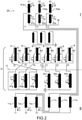
- Figure 2 shows the connection diagram of the combination of a step-down autotransformer 20 of constant voltage ratio with an asymmetric three core PST according to the invention.
- the invention can also be applied to a step-up transformer.
- the autotransformer has 2 windings, the high voltage winding (the primary or excitation winding) comprising, or made of, two coils, 51s (resp.52s, 53s, also named “series” coils) and 51c (resp.52c, 53c, also named “common” coils) and the medium voltage winding (the secondary winding or load) comprising, or made of, common coil 51c (resp.52c, 53c).
- the high voltage winding the primary or excitation winding
- 51s resp.52s, 53s, also named “series” coils
- 51c resp.52c, 53c, also named “common” coils
- the medium voltage winding comprising, or made of, common coil 51c (resp.52c, 53c).
- the autotransformer may also comprise stabilizing and/or test windings, as indicated on figure 2 (and also on figures 4 , 5 and 6 ).
- Series coil 51s (resp. 52s, 53s) is connected between medium voltage line line Y1 (resp.Y2, Y3) and high voltage (HV) line S1 (resp.S2, S3).
- Medium voltage coil 51c (resp. 52c, 53c) is connected between neutral N and medium voltage (MV) line Y1 (resp.Y2, Y3).
- Line Y1 (resp.Y2, Y3) is connected to coil 71v (resp. 72v, 73v), which is itself connected in series with coil 71p (resp. 72p, 73p).
- the level of the output voltage (to L1, resp. L2, L3) is mainly regulated by coil 71v (resp. 72v, 73v) (although it must be noted that there is no complete separation between voltage regulation and phase shift angle control).
- phase angle ⁇ p of the output voltage (to L1, resp. L2, L3) is mainly regulated by coil 71p (resp. 72p, 73p) (here again, it is noted that there is no complete separation between voltage regulation and phase shift angle control).
- Each coil 4, resp.6, 8 of both connected exciting windings is located in a first tank I, where it belongs to a first core together with the corresponding coils 51s, 51c, resp.52s, 52c, 53s, 53c, of the autotransformer (see figure 2 ). More precisely, coil 4, resp.6, 8, and coils 51s, 51c, resp.52s, 52c, 53s, 53c, are mounted on a same leg (or column) of the core (one leg (or column) per phase), not represented on figure 2 .
- Each coil 41p, resp. 42p, 43p of the delta connected winding (41p, 42p, 43p) and each coil 41v, resp. 42v, 43v of the star connected winding (41v, 42v, 43v) is preferably located in a second tank II, where it belongs to a second and third core together with one of the series L windings 71p-73p, 71v-73v (see figure 2 ), the dashed line 11 showing the separation between both tanks I and II. More precisely, both coils 41p and 71p are mounted on a same magnetic core, not represented on figure 2 ; the same applies to coils 42p and 72p, resp. 43p and 73p, 41v, and 71v, 42v and 72v, one magnetic core being provided for each phase.
- the PST transformer according to the invention in combination with an autotransformer, has 7 windings:
- Figure 3A shows a single phase equivalent electrical scheme of a single phase of the device according to figure 2 . It has to be noted that this scheme is valid for any of the 3 phases.
- the PST comprises both exciting windings sharing that same tap coil 4 which, as explained above interacts with the autotransformer 20. Said windings excite both voltage regulation coil 41v, interacting with coil 71v, and phase regulation coil 41p, interacting with coil 71p.
- Each tap of tap coil 4 regulates a number N xv , resp. N xp , of coil turns, which regulates a current j, resp. i, flowing to coil 41v, resp. 41p, thereby exciting voltage regulation coil 41v, resp. phase regulation coil 41p.
- the level of input voltage of coil 71v is regulated by its interaction with coil 41v of the PST.
- the voltage level is increased from e c 1 to e c 1 + e slv .
- phase of this regulated voltage is then regulated by the interaction of coil 71p with coil 41p of the PST.
- a voltage e slp is added to voltage e slv , with respect to which it is shifted by 90°.
- V ⁇ l e c 1 ⁇ + e slv ⁇ + e slp ⁇
- the modulus of V l is regulated on a no-load defined range of voltage and the phase of V l is controlled on a defined no-load range.
- a dephasing angle of between ⁇ 8° up to + 25° can be obtained by the PST according to the invention).
- the phase-angle on load depends on the load current modulus and on the total impedance of the autotransformer and of the phase-shifting transformer as shown in Annex E of IEC/IEEE 60076-57-1202 standard.
- a no-load phase-shift range of +/- 25° may become +20°/- 30° on load.
- a further constant dephasing angle may be added due to the load.
- FIG. 3B shows the corresponding voltage, resp. current, diagrams.
- the output voltage V l results from the input voltage V s , the intensity level of which is reduced down to e c + e slv which, in turn, is phase shifted by e slp .
- the resulting phase angle is ⁇ p , which depends on the relative sizes of e c , e slv and e slp .
- the modulus of the resulting current I xp + I xv flowing through the coils common to the two exciting windings is much lower than the sum of the moduli of the currents I xp and I xv in quadrature.
- the invention was explained in combination with a step-down transformer, but can be applied as well to a step-up transformer.
- the connection diagram of the combination of a step-up autotransformer with an asymmetric three core PST according to the invention is obtained from figure 2 by inverting the source and load sides, (S1,S2,S3) and the corresponding references becoming (L1,L2,L32) and vice-versa.
- Figure 4 shows a connection diagram of the combination of a step-up autotransformer 20 of constant voltage ratio with an asymmetric three core PST according to the invention: the numerical references are the same as on figure 2 , only the currents I L1 , I L2 , I L3 (at the output of 51s, 52s, 53s on figure 4 ) and I S1 , I S2 and I S3 (at the input of 71p, 72p, 73p on figure 4 ) being inverted.
- Figure 5 shows a variant of the invention, in which a constant dephasing is introduced by connecting further coils 41'p, resp. 42'p, 43'p, to coils 41p, resp. 42p, 43p of the excited windings 41p, 42p, 43p.
- a further constant phase shift is thus added.
- the phase-angle on load depends on the load current modulus and on the total impedance of the autotransformer and of the phase-shifting transformer (as shown in Annex E of IEC/IEEE 60076-57-1202 standard).
- the load angle drop has a constant sign. For example, a no-load phase-shift range of +/- 25°, may become +20° (+25°-5°)/-30° (-25°-5°) on load.
- the constant additional phase-shift of 5° allows the range to be +25° (+25°-5°+5°)/- 25° (-25° -5° +5°) on rated load, rated voltage.
- Figure 6 shows an application of a PST according to the invention to a transformer of the "quad booster” type (or “quadrature booster", an autotransformer of ratio 1), comprising 3 coils 51c, 52c, 53c in which the voltage of each HV line S1 (resp.S2, S3) is directly applied to line Y1 (resp.Y2, Y3).
- Common coil 51c (resp. 52c, 53c) is connected between neutral N and HV line S1 (resp.S2, S3).
- a single phase equivalent electrical scheme of a single phase of device according to figure 6 including a quadbooster, is derived from figure 3A by deleting coil 51s.
- All circuits described in this application can further comprise cabinets with mechanical axes (to control the tap changers) mounted on the transformer tank, with control possibilities from the cabinet and remotely from a control room.
Landscapes
- Engineering & Computer Science (AREA)
- Power Engineering (AREA)
- Ac-Ac Conversion (AREA)
- Control Of Electrical Variables (AREA)
- Coils Or Transformers For Communication (AREA)
Abstract
- 2 exciting windings (X1, X2, X3, Z1, Z2, Z3) sharing the same 3 double taped coils (4, 6, 8),
- a first excited winding comprising 3 connected coils (41p, 42p, 43p), for a phase shift regulation,
- a second excited winding comprising 3 connected coils (41v, 42v, 43v), for a voltage regulation;
each of said 2 exciting windings regulating the voltage of one coil of said second excited winding (41p, 42p, 43p), and regulating the voltage level of one coil of said first excited winding (41v, 42v, 43v).
Description
- The invention relates to a phase shifting transformer (PST) and to an autotransformer combined with such a PST.
- Transmission system operators (TSO) in some countries request that autotransformers for interconnection of networks of different voltages be provided with facilities for controlling the phase shift angle in addition to voltage regulation.
- Coarse but effective solutions are adopted by some operators, consisting in using in series a conventional network autotransformer with a symmetrical phase shifter assembly.
- In general, the voltage level of the medium-voltage network is less than or equal to 245 kV and allows the use of single core symmetrical PSTs (the coils of the PST windings being arranged on one single-core) with tap changers directly connected to the lines. However, these devices require two tap-changers per phase, which means six tap-changers in total; since the autotransformer also includes 3 tap-changers, it makes a total of 9 single-phase tap-changers in the whole system (autotransformer and PST). Sometimes the requested transfer power is very large, and the medium voltage line current is too high for the types of OLTC ("On Load Tap Changer") existing in suppliers' catalogs. PSTs with two magnetic circuits are then required.
- The cost of these coarse solutions is very high, and some operators seek for alternative, preferably more competitive, solutions.
- The conventional symmetrical PST solutions with one magnetic circuit referenced in the common standard IEC IEEE 60076-57-1202 with respectively the connection phase displacement symbol P S0-3/9 and D S0-3/9 connected in series with conventional step-down autotransformer does allow high power transfers controlled over limited and larger phase-shift angles between continental/national networks of high voltage level and regional networks of medium voltage level.
- However, these solutions require the use of six single phase OLTCs for phase-shift control and three additional OLTCs for voltage regulation, making this solution expensive and sometimes even not applicable when the line current of the medium network is too large for the available OLTCs in suppliers' catalogs.
- The present invention provides a solution to facilitate and allow the combination on the same magnetic circuit, or magnetic core, of an autotransformer, for example a step-down or a step-up autotransformer, with a voltage regulation and a phase regulation of the exciting transformer of a two-core asymmetrical phase shifter.
- In a phase-shifting transformer (PST) according to the invention, two on-load tap-changer sets are connected to the same taped coil of the excitation (or exciting) transformer to form two windings :
- a first winding to excite the winding of a series active part dedicated to the voltage regulation;
- a second winding to excite the winding of a series active part dedicated to the control of the phase shift angle.
- The primary winding of the exciting unit draws power from the network.
- Thus, the invention relates in particular to a phase shifting transformer comprising:
- 3 double tapped coils of 2 exciting windings,
- 3 coils of a first excited winding, in view of a phase shift regulation;
- 3 coils of a second excited winding in view of a voltage regulation.
- Each of said 3 double tapped coils of both exciting windings can regulate the voltage of one of said 3 coils of the first excited winding, and can regulate the voltage of one of said 3 coils of the second excited winding.
- Each of said 3 double tapped coils windings can be star (respectively delta) connected.
- Said 3 coils winding, in view of a phase shift regulation, being delta (respectively star) connected.
- Said 3 coils winding, in view of a voltage regulation, being star (respectively delta) connected.
- A PST according to the invention includes 3 single-phase tap-changers for the phase shift-angle control and 3 single-phase tap-changers for the voltage regulation.
- The 3 coils of the first excited winding, in view of a phase shift regulation, and the 3 coils of the second excited winding, in view of a voltage regulation, can provide series windings with currents in quadrature. In other words, a device according to the invention has a connection diagram combining the use of the same tapped coil by two sets of on-load changers to form two separate windings loading the same tapped coil with currents in quadrature.
- The modulus of the resulting current flowing through the coil common to the two exciting windings is much lower than the sum of the moduli of the currents in quadrature.
- The invention requires only one tapped coil for each phase instead of two, said tapped coil having a dimensioning power significantly less than the sum of the dimensioning powers of the 2 separate coils known in the art: indeed, for a 1-phase coil, the dimensioning power is the product of the maximum voltage at both ends of the coil time the maximum current that can flows through the coil; for 3-phase coil, it is the cubic root of said product. In other words, the size of the resulting coil implemented in the invention is less than the sum of the size of the separate coils.
- Furthermore, the invention, by grouping each 2 tapped coils into a single one, makes possible some general diagrams (see for example
figures 2 and5 ) of phase shifting transformers. - A phase shifting transformer according to the invention can further comprise means to add a further dephasing angle. Said means may comprise at least 3 coils, each one of said 3 coils being connected in series with a different one of said 3 connected coils of said first excited winding.
- The invention also concerns a transformer comprising an autotransformer and a phase shifting transformer according to the invention.
- Said autotransformer can be of the step-down type or of the step-up type.
- Alternatively, it can be a quadbooster (or quadrature booster) (autotransformer of ratio 1).
- The invention also concerns a method for regulating the voltage of an autotransformer, implementing a phase shift transformer (PST) according to the invention, or a method for regulating the voltage of a transformer according to the invention, wherein:
- the level of the voltage provided by said autotransformer or of said transformer is regulated by a 3 coils winding (or excited winding) of said PST;
- the phase provided by said autotransformer or of said transformer is regulated by the other 3 coils winding (or excited winding) of said PST.
-
-
Figure 1 shows an embodiment of the main parts (exciting windings and excited windings) of a phase shifting transformer according to the invention; -
Figure 2 shows the connection diagram of the combination of a step-down autotransformer of constant voltage ratio with the excitation transformer of an asymmetric three core phase shifting transformer according to the invention; -
Figure 3A is an electric equivalent scheme of a single phase of the device according tofigure 2 ; -
Figures 3B and 3C are voltage and current diagrams of a single phase of the device according tofigure 2 ; -
Figure 4 shows the connection diagram of the combination of a step-up autotransformer of constant voltage ratio with the excitation transformer of an asymmetric three core phase shifting transformer;-Figure 5 shows a variant offigure 2 , further comprising means for a further phase shift; -
Figure 6 shows a variant offigure 2 for a quadrature booster. - The present invention is described in the context of a three-phase network. In particular, without it being necessary to specify it and unless otherwise indicated, the mention of a winding will refer to any phase, the explanation given for one phase applying to the other phases.
-
Figure 1 shows an embodiment of the main parts (exciting winding and excited windings) of aphase shifting transformer 2 according to the invention. - On this figure (and on
figure 2 ), in order to facilitate understanding, theexciting coils single coil 4, which has twotap changers 40, 40', is implemented for bothvoltage adaptation coil 41v and phaseshifting adaptation coil 43p. The same applies tocoil 6, resp. and to coil 8, with respect tovoltage adaptation coil 42v and phaseshifting adaptation coil 41p, resp. tovoltage adaptation coil 43v and phaseshifting adaptation coil 42p. - In other words, for each
exciting coil 4, resp. 6, 8: - one tap changer 40', resp.60', 80', regulates the voltage provided to the series
active coil 41v, resp. 42v, 43v for voltage level regulation, - the
other tap changer 40, resp.60, 80, regulates the voltage provided to the seriesactive coil 43p, resp. 41p, 42p for phase shift angle control. -
Exciting coils - The windings excited by said
exciting coils 4, resp. 6, 8 comprise: - delta connected winding 43p, 41p, 42p (which is connected between X1, X2 and X3), in view of a phase shift regulation; it has to be noted that additional constant phase shift angles may be allowed through introduction of additional coils and special connection of these coils, for example a delta (or extended delta) connection; other types of connections (zig-zag or polygon for example) of additional coils are available;
- star connected winding 41v, 42v, 43v (which is connected between n and Z1, Z2, Z3) in view of a voltage regulation.
- Alternatively,
exciting coils -
Figure 2 shows the connection diagram of the combination of a step-down autotransformer 20 of constant voltage ratio with an asymmetric three core PST according to the invention. In a variant, the invention can also be applied to a step-up transformer. - For each phase, the autotransformer has 2 windings, the high voltage winding (the primary or excitation winding) comprising, or made of, two coils, 51s (resp.52s, 53s, also named "series" coils) and 51c (resp.52c, 53c, also named "common" coils) and the medium voltage winding (the secondary winding or load) comprising, or made of,
common coil 51c (resp.52c, 53c). - The autotransformer may also comprise stabilizing and/or test windings, as indicated on
figure 2 (and also onfigures 4 ,5 and6 ). -
Series coil 51s (resp. 52s, 53s) is connected between medium voltage line line Y1 (resp.Y2, Y3) and high voltage (HV) line S1 (resp.S2, S3). -
Medium voltage coil 51c (resp. 52c, 53c) is connected between neutral N and medium voltage (MV) line Y1 (resp.Y2, Y3). - Line Y1 (resp.Y2, Y3) is connected to
coil 71v (resp. 72v, 73v), which is itself connected in series withcoil 71p (resp. 72p, 73p). - The level of the output voltage (to L1, resp. L2, L3) is mainly regulated by
coil 71v (resp. 72v, 73v) (although it must be noted that there is no complete separation between voltage regulation and phase shift angle control). - The phase angle αp of the output voltage (to L1, resp. L2, L3) is mainly regulated by
coil 71p (resp. 72p, 73p) (here again, it is noted that there is no complete separation between voltage regulation and phase shift angle control). - Each
coil 4, resp.6, 8 of both connected exciting windings is located in a first tank I, where it belongs to a first core together with the correspondingcoils figure 2 ). More precisely,coil 4, resp.6, 8, and coils 51s, 51c, resp.52s, 52c, 53s, 53c, are mounted on a same leg (or column) of the core (one leg (or column) per phase), not represented onfigure 2 . - Each
coil 41p, resp. 42p, 43p of the delta connected winding (41p, 42p, 43p) and eachcoil 41v, resp. 42v, 43v of the star connected winding (41v, 42v, 43v) is preferably located in a second tank II, where it belongs to a second and third core together with one of theseries L windings 71p-73p, 71v-73v (seefigure 2 ), the dashedline 11 showing the separation between both tanks I and II. More precisely, bothcoils figure 2 ; the same applies to coils 42p and 72p, resp. 43p and 73p, 41v, and 71v, 42v and 72v, one magnetic core being provided for each phase. - Thus, the PST transformer according to the invention, in combination with an autotransformer, has 7 windings:
- the excitation winding 51s, 52s, 53s (which is common to both the autotransformer and the tapped exciting windings);
- both tapped exciting windings, sharing the same double tapped
coils - and two
excited windings series windings - and the two
series windings -
Figure 3A shows a single phase equivalent electrical scheme of a single phase of the device according tofigure 2 . It has to be noted that this scheme is valid for any of the 3 phases. - For clarity's sake, some currents are not indicated on
figure 3A : current Is flows incoil 51s, Ic flows incoil 51c, Iev flows incoil 41p, Il flows incoil 71v, Ixp and Ixv flow incoil 4. - Medium voltage on line Y1 is reduced compared to the input voltage Vs1, according to the number of winding turns Nss1, resp. Nc1, of the
coils 51s, resp.51c. - The PST comprises both exciting windings sharing that
same tap coil 4 which, as explained above interacts with theautotransformer 20. Said windings excite bothvoltage regulation coil 41v, interacting withcoil 71v, andphase regulation coil 41p, interacting withcoil 71p. Each tap oftap coil 4 regulates a number Nxv, resp. Nxp, of coil turns, which regulates a current j, resp. i, flowing tocoil 41v, resp. 41p, thereby excitingvoltage regulation coil 41v, resp.phase regulation coil 41p. - The level of input voltage of
coil 71v is regulated by its interaction withcoil 41v of the PST. In this example, as can be seen onfigure 3A , the voltage level is increased frome c1 toe c1 +eslv . - The phase of this regulated voltage is then regulated by the interaction of
coil 71p withcoil 41p of the PST. In this example, as can be seen onfigure 3A , a voltageeslp is added to voltageeslv , with respect to which it is shifted by 90°. - The final output voltage
Vl is given by:
- The level and the phase of this output voltage Vl are thus both regulated, the level of Vl being given by the ratio Nev/Nsv = Vl/Vs.
- By regulating both the voltage level (eslv on
figure 3A ) and the intensity of the phase shifted voltage (eslp onfigure 3A ), the modulus of Vl is regulated on a no-load defined range of voltage and the phase of Vl is controlled on a defined no-load range. For example, a dephasing angle of between ± 8° up to + 25° can be obtained by the PST according to the invention). The phase-angle on load depends on the load current modulus and on the total impedance of the autotransformer and of the phase-shifting transformer as shown in Annex E of IEC/IEEE 60076-57-1202 standard. For example a no-load phase-shift range of +/- 25°, may become +20°/- 30° on load. In other words, a further constant dephasing angle may be added due to the load. -
Figures 3B , resp. 3C, shows the corresponding voltage, resp. current, diagrams. The output voltageVl results from the input voltageVs , the intensity level of which is reduced down to ec + eslv which, in turn, is phase shifted byeslp . The resulting phase angle is αp, which depends on the relative sizes ofec ,eslv andeslp . In a method according to the invention it is possible to control the modulus ofV 1 by (througheslv ) and/or to control the phase angle value (througheslp ) . - Concerning
figure 3C : - currents Ixv and Ixp flow in
coils - current Iev flows in
coil 41v and current iep incoil 41 p; both currents have the same direction as current Il that flows incoils -
coils -
coils - The modulus of the resulting current Ixp + Ixv flowing through the coils common to the two exciting windings (one exciting winding being the set of coils (4, 6, 8) connected to n and (X1, X2, X3) through the set of OLTCs for phase control, the other one being the set of coils (4, 6, 8) connected to n and (Z1, Z2, Z3) through the set of OLTCs for voltage regulation) is much lower than the sum of the moduli of the currents Ixp and Ixv in quadrature.
- The invention was explained in combination with a step-down transformer, but can be applied as well to a step-up transformer. The connection diagram of the combination of a step-up autotransformer with an asymmetric three core PST according to the invention is obtained from
figure 2 by inverting the source and load sides, (S1,S2,S3) and the corresponding references becoming (L1,L2,L32) and vice-versa.Figure 4 shows a connection diagram of the combination of a step-upautotransformer 20 of constant voltage ratio with an asymmetric three core PST according to the invention: the numerical references are the same as onfigure 2 , only the currents IL1, IL2, IL3 (at the output of 51s, 52s, 53s onfigure 4 ) and IS1, IS2 and IS3 (at the input of 71p, 72p, 73p onfigure 4 ) being inverted. -
Figure 5 shows a variant of the invention, in which a constant dephasing is introduced by connecting further coils 41'p, resp. 42'p, 43'p, tocoils 41p, resp. 42p, 43p of theexcited windings -
Figure 6 shows an application of a PST according to the invention to a transformer of the "quad booster" type (or "quadrature booster", an autotransformer of ratio 1), comprising 3coils Common coil 51c (resp. 52c, 53c) is connected between neutral N and HV line S1 (resp.S2, S3). A single phase equivalent electrical scheme of a single phase of device according tofigure 6 , including a quadbooster, is derived fromfigure 3A by deletingcoil 51s. - All circuits described in this application can further comprise cabinets with mechanical axes (to control the tap changers) mounted on the transformer tank, with control possibilities from the cabinet and remotely from a control room.
Claims (12)
- Phase shifting transformer (2) comprising:- 2 exciting windings (4, 6, 8, n, X1, X2, X3, Z1, Z2, Z3) sharing the same 3 double taped coils (4, 6, 8),- a first excited winding comprising 3 connected coils (41p, 42p, 43p), for a phase shift regulation,- a second excited winding comprising 3 connected coils (41v, 42v, 43v), for a voltage regulation;
each of said 2 exciting windings regulating the voltage of one coil of said second excited winding (41p, 42p, 43p), and regulating the voltage level of one coil of said first excited winding (41v, 42v, 43v). - Phase shifting transformer according to claim 1, said 2 exciting windings (4, 6, 8, n, X1, X2, X3, Z1, Z2, Z3) sharing the same 3 double taped coils (4, 6, 8) being star, resp. delta, connected.
- Phase shifting transformer according to claim 1 or 2, said 3 connected coil winding (41p, 42p, 43p), for a phase shift regulation, being delta, resp. star, connected.
- Phase shifting transformer according to claim 1 to 3, said 3 connected coil winding (41p, 42p, 43p), for a phase shift regulation, being star, resp. delta, connected.
- Phase shifting transformer according to claim 1 to 4, further comprising means (41'p, 42'p, 43'p) to add a further constant dephasing angle.
- Phase shifting transformer according to claim 5, said means (41'p, 42'p, 43'p) to add a further constant dephasing angle comprising at least 3 coils, each one of said 3 coils being connected in series with one of said 3 connected coils of said first excited winding.
- Transformer comprising an autotransformer (20) and a phase shifting transformer according to any of claims 1 to 6.
- Transformer according to claim 7, said autotransformer (20) being of the step-down type.
- Transformer according to claim 7, said autotransformer (20) being of the step-up type.
- Transformer according to claim 7, said autotransformer (20) being a quadbooster.
- Transformer according to any of claims 7 to 10, the 2 double tapped coil windings (4, 6, 8) being in a first tank (I), the 3 coils winding (41p, 42p, 43p), in view of a phase shift regulation, and the 3 coils winding (41v, 42v, 43v) in view of a voltage regulation, being in a second tank (II).
- Method for regulating the voltage of a transformer according to any of claims 7 to 11, wherein:- the level of the voltage provided by said autotransformer is regulated by a 3 coils excited winding of said phase shifting transformer;- the phase provided by said autotransformer is regulated by the other 3 coils excited winding of said phase shifting transformer.
Priority Applications (5)
| Application Number | Priority Date | Filing Date | Title |
|---|---|---|---|
| EP20194716.5A EP3965282A1 (en) | 2020-09-04 | 2020-09-04 | Phase shifting transformers comprising a single coil for two exciting windings for voltage regulation and for phase shift angle regulation |
| US18/042,666 US20230353059A1 (en) | 2020-09-04 | 2021-09-01 | Phase shifting transformers comprising a single coil for two exciting windings for voltage regulation and for phase shift angle regulation |
| AU2021338484A AU2021338484A1 (en) | 2020-09-04 | 2021-09-01 | Phase shifting transformers comprising a single coil for two exciting windings for voltage regulation and for phase shift angle regulation |
| CA3191852A CA3191852A1 (en) | 2020-09-04 | 2021-09-01 | Phase shifting transformers comprising a single coil for two exciting windings for voltage regulation and for phase shift angle regulation |
| PCT/EP2021/074084 WO2022049099A1 (en) | 2020-09-04 | 2021-09-01 | Phase shifting transformers comprising a single coil for two exciting windings for voltage regulation and for phase shift angle regulation |
Applications Claiming Priority (1)
| Application Number | Priority Date | Filing Date | Title |
|---|---|---|---|
| EP20194716.5A EP3965282A1 (en) | 2020-09-04 | 2020-09-04 | Phase shifting transformers comprising a single coil for two exciting windings for voltage regulation and for phase shift angle regulation |
Publications (1)
| Publication Number | Publication Date |
|---|---|
| EP3965282A1 true EP3965282A1 (en) | 2022-03-09 |
Family
ID=72428137
Family Applications (1)
| Application Number | Title | Priority Date | Filing Date |
|---|---|---|---|
| EP20194716.5A Pending EP3965282A1 (en) | 2020-09-04 | 2020-09-04 | Phase shifting transformers comprising a single coil for two exciting windings for voltage regulation and for phase shift angle regulation |
Country Status (5)
| Country | Link |
|---|---|
| US (1) | US20230353059A1 (en) |
| EP (1) | EP3965282A1 (en) |
| AU (1) | AU2021338484A1 (en) |
| CA (1) | CA3191852A1 (en) |
| WO (1) | WO2022049099A1 (en) |
Cited By (1)
| Publication number | Priority date | Publication date | Assignee | Title |
|---|---|---|---|---|
| CN119724859A (en) * | 2025-02-17 | 2025-03-28 | 国网江苏省电力有限公司电力科学研究院 | A winding connection structure of an auto-coupling step-down phase-shifting transformer |
Families Citing this family (1)
| Publication number | Priority date | Publication date | Assignee | Title |
|---|---|---|---|---|
| CN118841243B (en) * | 2024-06-27 | 2025-08-19 | 南方电网科学研究院有限责任公司 | Single-core different-column self-coupling phase-shifting transformer and phase angle adjusting device |
Citations (3)
| Publication number | Priority date | Publication date | Assignee | Title |
|---|---|---|---|---|
| DE1912247A1 (en) * | 1969-03-10 | 1970-09-24 | Bbc Brown Boveri & Cie | Network coupling through at least two single induction regulators |
| US6396248B1 (en) * | 2000-12-04 | 2002-05-28 | Abb T&D Technology Ltd. | Versatile power flow transformers for compensating power flow in a transmission line |
| EP3392996A1 (en) * | 2017-04-21 | 2018-10-24 | ABB Schweiz AG | Longitudinal voltage regulation at the line terminals of a phase shifting transformer |
Family Cites Families (3)
| Publication number | Priority date | Publication date | Assignee | Title |
|---|---|---|---|---|
| SE510452C2 (en) * | 1997-02-03 | 1999-05-25 | Asea Brown Boveri | Transformer with voltage regulator |
| US6198647B1 (en) * | 2000-07-28 | 2001-03-06 | Rockwell Technologies, Llc | Twelve-phase transformer configuration |
| US11967453B2 (en) * | 2019-04-17 | 2024-04-23 | The Boeing Company | Transformer and method of generating multiple multiphase output signals |
-
2020
- 2020-09-04 EP EP20194716.5A patent/EP3965282A1/en active Pending
-
2021
- 2021-09-01 WO PCT/EP2021/074084 patent/WO2022049099A1/en not_active Ceased
- 2021-09-01 CA CA3191852A patent/CA3191852A1/en active Pending
- 2021-09-01 US US18/042,666 patent/US20230353059A1/en active Pending
- 2021-09-01 AU AU2021338484A patent/AU2021338484A1/en active Pending
Patent Citations (3)
| Publication number | Priority date | Publication date | Assignee | Title |
|---|---|---|---|---|
| DE1912247A1 (en) * | 1969-03-10 | 1970-09-24 | Bbc Brown Boveri & Cie | Network coupling through at least two single induction regulators |
| US6396248B1 (en) * | 2000-12-04 | 2002-05-28 | Abb T&D Technology Ltd. | Versatile power flow transformers for compensating power flow in a transmission line |
| EP3392996A1 (en) * | 2017-04-21 | 2018-10-24 | ABB Schweiz AG | Longitudinal voltage regulation at the line terminals of a phase shifting transformer |
Cited By (1)
| Publication number | Priority date | Publication date | Assignee | Title |
|---|---|---|---|---|
| CN119724859A (en) * | 2025-02-17 | 2025-03-28 | 国网江苏省电力有限公司电力科学研究院 | A winding connection structure of an auto-coupling step-down phase-shifting transformer |
Also Published As
| Publication number | Publication date |
|---|---|
| CA3191852A1 (en) | 2022-03-10 |
| AU2021338484A1 (en) | 2023-03-09 |
| US20230353059A1 (en) | 2023-11-02 |
| WO2022049099A1 (en) | 2022-03-10 |
Similar Documents
| Publication | Publication Date | Title |
|---|---|---|
| US3818402A (en) | Tap-changing series-multiple transformer system | |
| US7049921B2 (en) | Auto-transformer for use with multiple pulse rectifiers | |
| US4156174A (en) | Phase-angle regulator | |
| CZ269899A3 (en) | Transformer with voltage regulator | |
| AU2021338484A1 (en) | Phase shifting transformers comprising a single coil for two exciting windings for voltage regulation and for phase shift angle regulation | |
| US6982884B1 (en) | Autotransformers to parallel AC to DC converters | |
| US4500829A (en) | Advance and retard phase-shift transformer | |
| JP3598126B2 (en) | Three-phase load voltage phase adjustment transformer | |
| US6011381A (en) | Three-phase auto transformer with two tap changers for ratio and phase-angle control | |
| US3254295A (en) | Buck boost transformer voltage controller with tap changing transformer system | |
| JP5026029B2 (en) | Current balancer and low voltage distribution system | |
| JPS6081811A (en) | On-load tap changing autotransformer | |
| JPH11186070A (en) | Single-phase autotransformer | |
| US2989685A (en) | Regulating transformer | |
| US3652925A (en) | Polyphase transformer device whose taps are changeable when loaded | |
| US2369038A (en) | Electric transformer | |
| US2380265A (en) | Adjustable transformer regulator | |
| US4638177A (en) | Rotating flux transformer | |
| CA1120112A (en) | Tap changing transformer | |
| JP2773096B2 (en) | Power distribution equipment | |
| JPS5834922B2 (en) | Tansoutanmakihen Atsukino Denatsuchiyouseihoshiki | |
| US1906210A (en) | Method of and means for electric voltage regulation | |
| CN108666116A (en) | The middle pressure pressure regulation method of power auto-transformer | |
| JPH0793213B2 (en) | Transformer with tap | |
| SU1206927A1 (en) | Twelve-phase converter |
Legal Events
| Date | Code | Title | Description |
|---|---|---|---|
| PUAI | Public reference made under article 153(3) epc to a published international application that has entered the european phase |
Free format text: ORIGINAL CODE: 0009012 |
|
| STAA | Information on the status of an ep patent application or granted ep patent |
Free format text: STATUS: THE APPLICATION HAS BEEN PUBLISHED |
|
| AK | Designated contracting states |
Kind code of ref document: A1 Designated state(s): AL AT BE BG CH CY CZ DE DK EE ES FI FR GB GR HR HU IE IS IT LI LT LU LV MC MK MT NL NO PL PT RO RS SE SI SK SM TR |
|
| STAA | Information on the status of an ep patent application or granted ep patent |
Free format text: STATUS: REQUEST FOR EXAMINATION WAS MADE |
|
| RBV | Designated contracting states (corrected) |
Designated state(s): AL AT BE BG CH CY CZ DE DK EE ES FI FR GB GR HR HU IE IS IT LI LT LU LV MC MK MT NL NO PL PT RO RS SE SI SK SM TR |
|
| 17P | Request for examination filed |
Effective date: 20220801 |
|
| P01 | Opt-out of the competence of the unified patent court (upc) registered |
Effective date: 20230522 |
|
| RAP3 | Party data changed (applicant data changed or rights of an application transferred) |
Owner name: GE VERNOVA TECHNOLOGY GMBH |