EP3965250A1 - Load-sharing with interconnected power generation - Google Patents
Load-sharing with interconnected power generation Download PDFInfo
- Publication number
- EP3965250A1 EP3965250A1 EP21191572.3A EP21191572A EP3965250A1 EP 3965250 A1 EP3965250 A1 EP 3965250A1 EP 21191572 A EP21191572 A EP 21191572A EP 3965250 A1 EP3965250 A1 EP 3965250A1
- Authority
- EP
- European Patent Office
- Prior art keywords
- gtg
- power
- gtgs
- controller
- load
- Prior art date
- Legal status (The legal status is an assumption and is not a legal conclusion. Google has not performed a legal analysis and makes no representation as to the accuracy of the status listed.)
- Granted
Links
Images


Classifications
-
- H—ELECTRICITY
- H02—GENERATION; CONVERSION OR DISTRIBUTION OF ELECTRIC POWER
- H02J—ELECTRIC POWER NETWORKS; CIRCUIT ARRANGEMENTS OR SYSTEMS FOR SUPPLYING OR DISTRIBUTING ELECTRIC POWER; SYSTEMS FOR STORING ELECTRIC ENERGY
- H02J3/00—Circuit arrangements for AC mains or AC distribution networks
- H02J3/38—Arrangements for feeding a single network from two or more generators or sources in parallel; Arrangements for feeding already energised networks from additional generators or sources in parallel
- H02J3/46—Controlling the sharing of generated power between the generators, sources or networks
- H02J3/48—Controlling the sharing of active power
-
- H—ELECTRICITY
- H02—GENERATION; CONVERSION OR DISTRIBUTION OF ELECTRIC POWER
- H02J—ELECTRIC POWER NETWORKS; CIRCUIT ARRANGEMENTS OR SYSTEMS FOR SUPPLYING OR DISTRIBUTING ELECTRIC POWER; SYSTEMS FOR STORING ELECTRIC ENERGY
- H02J3/00—Circuit arrangements for AC mains or AC distribution networks
- H02J3/38—Arrangements for feeding a single network from two or more generators or sources in parallel; Arrangements for feeding already energised networks from additional generators or sources in parallel
- H02J3/46—Controlling the sharing of generated power between the generators, sources or networks
- H02J3/466—Scheduling or selectively controlling the operation of the generators or sources, e.g. connecting or disconnecting generators to meet a demand
-
- H—ELECTRICITY
- H02—GENERATION; CONVERSION OR DISTRIBUTION OF ELECTRIC POWER
- H02J—ELECTRIC POWER NETWORKS; CIRCUIT ARRANGEMENTS OR SYSTEMS FOR SUPPLYING OR DISTRIBUTING ELECTRIC POWER; SYSTEMS FOR STORING ELECTRIC ENERGY
- H02J3/00—Circuit arrangements for AC mains or AC distribution networks
- H02J3/38—Arrangements for feeding a single network from two or more generators or sources in parallel; Arrangements for feeding already energised networks from additional generators or sources in parallel
- H02J3/46—Controlling the sharing of generated power between the generators, sources or networks
-
- F—MECHANICAL ENGINEERING; LIGHTING; HEATING; WEAPONS; BLASTING
- F01—MACHINES OR ENGINES IN GENERAL; ENGINE PLANTS IN GENERAL; STEAM ENGINES
- F01D—NON-POSITIVE DISPLACEMENT MACHINES OR ENGINES, e.g. STEAM TURBINES
- F01D15/00—Adaptations of machines or engines for special use; Combinations of engines with devices driven thereby
- F01D15/10—Adaptations for driving, or combinations with, electric generators
-
- H—ELECTRICITY
- H02—GENERATION; CONVERSION OR DISTRIBUTION OF ELECTRIC POWER
- H02J—ELECTRIC POWER NETWORKS; CIRCUIT ARRANGEMENTS OR SYSTEMS FOR SUPPLYING OR DISTRIBUTING ELECTRIC POWER; SYSTEMS FOR STORING ELECTRIC ENERGY
- H02J13/00—Circuit arrangements for providing remote monitoring or remote control of equipment in a power distribution network
- H02J13/16—Circuit arrangements for providing remote monitoring or remote control of equipment in a power distribution network the power network being controlled at grid-level, e.g. using aggregators
-
- H—ELECTRICITY
- H02—GENERATION; CONVERSION OR DISTRIBUTION OF ELECTRIC POWER
- H02J—ELECTRIC POWER NETWORKS; CIRCUIT ARRANGEMENTS OR SYSTEMS FOR SUPPLYING OR DISTRIBUTING ELECTRIC POWER; SYSTEMS FOR STORING ELECTRIC ENERGY
- H02J3/00—Circuit arrangements for AC mains or AC distribution networks
- H02J3/38—Arrangements for feeding a single network from two or more generators or sources in parallel; Arrangements for feeding already energised networks from additional generators or sources in parallel
- H02J3/381—Dispersed generators
-
- H—ELECTRICITY
- H02—GENERATION; CONVERSION OR DISTRIBUTION OF ELECTRIC POWER
- H02J—ELECTRIC POWER NETWORKS; CIRCUIT ARRANGEMENTS OR SYSTEMS FOR SUPPLYING OR DISTRIBUTING ELECTRIC POWER; SYSTEMS FOR STORING ELECTRIC ENERGY
- H02J2101/00—Supply or distribution of decentralised, dispersed or local electric power generation
- H02J2101/10—Dispersed power generation using fossil fuels, e.g. diesel generators
-
- Y—GENERAL TAGGING OF NEW TECHNOLOGICAL DEVELOPMENTS; GENERAL TAGGING OF CROSS-SECTIONAL TECHNOLOGIES SPANNING OVER SEVERAL SECTIONS OF THE IPC; TECHNICAL SUBJECTS COVERED BY FORMER USPC CROSS-REFERENCE ART COLLECTIONS [XRACs] AND DIGESTS
- Y02—TECHNOLOGIES OR APPLICATIONS FOR MITIGATION OR ADAPTATION AGAINST CLIMATE CHANGE
- Y02E—REDUCTION OF GREENHOUSE GAS [GHG] EMISSIONS, RELATED TO ENERGY GENERATION, TRANSMISSION OR DISTRIBUTION
- Y02E40/00—Technologies for an efficient electrical power generation, transmission or distribution
- Y02E40/70—Smart grids as climate change mitigation technology in the energy generation sector
-
- Y—GENERAL TAGGING OF NEW TECHNOLOGICAL DEVELOPMENTS; GENERAL TAGGING OF CROSS-SECTIONAL TECHNOLOGIES SPANNING OVER SEVERAL SECTIONS OF THE IPC; TECHNICAL SUBJECTS COVERED BY FORMER USPC CROSS-REFERENCE ART COLLECTIONS [XRACs] AND DIGESTS
- Y04—INFORMATION OR COMMUNICATION TECHNOLOGIES HAVING AN IMPACT ON OTHER TECHNOLOGY AREAS
- Y04S—SYSTEMS INTEGRATING TECHNOLOGIES RELATED TO POWER NETWORK OPERATION, COMMUNICATION OR INFORMATION TECHNOLOGIES FOR IMPROVING THE ELECTRICAL POWER GENERATION, TRANSMISSION, DISTRIBUTION, MANAGEMENT OR USAGE, i.e. SMART GRIDS
- Y04S10/00—Systems supporting electrical power generation, transmission or distribution
- Y04S10/12—Monitoring or controlling equipment for energy generation units, e.g. distributed energy generation [DER] or load-side generation
Definitions
- the subject matter disclosed herein relates generally to a module for load-sharing in a power generation system. Specifically, the module is used to maintain a stable operation of a group of electrical power generators in different load sharing scenarios.
- a centralized controller may be used to manage the load sharing and other parallel tasks. However, when the centralized controller is offline due to technical or environmental problems (e.g., extreme weather events), the parallel tasks may be inhibited, resulting in unevenly distributed loads among the generators and/or unstable power generation.
- a controller of a gas-turbine generator receives an indication of a status of another GTG over an interconnection bus. Based on the status of the other GTG, the controller determines a power level to be generated by the GTG and drives the GTG to output the power level.
- GTG gas-turbine generator
- a non-transitory, computer-readable medium storing instructions.
- the instructions when executed by one or more processors, cause the one or more processors to receive, at a controller of a gas-turbine generator (GTG), an indication of power generated in a set of GTGs (including the GTG) that are part of a power network.
- the instructions also cause the one or more processors to receive, at the controller, an indication of a status change of a switch in the power network, in which the status change includes a toggle of a connection of one of the set of GTGs to the power network or a connection of the power network to a grid, and the indication is received over an interconnect bus interconnecting a set of controllers corresponding to the set of GTGs.
- the instructions also cause the one or more processors to determine, based on the status of the switch and the power generated, whether a change in power generated by the power network is to occur.
- the instructions also cause the one or more processors to drive, using the controller, the GTG based at least in part on the determination of whether to change the power generated.
- a system in a third embodiment, includes a controller that includes a memory storing instructions and a processor that is used to execute the instructions.
- the instructions when executed by the processor, cause the processor to control power generation in a gas-turbine generator (GTG) in a power network that includes a set of GTGs.
- GTG gas-turbine generator
- the instructions when executed by the processor, cause the processor to: receive an indication that another GTG of the set of GTGs is within a threshold of a maximum power generation of the other GTG, in which the indication is received over an interconnect bus that interconnects the controllers of the set of GTGs.
- the instructions also cause the processor to receive a command that the GTG is to be shut down and, based on the indication, prevent the shutdown of the GTG and send a warning to an operator.
- Power generation systems are used to convert energy sources into electrical power.
- the energy sources may be hydraulic, coal, natural gas, crude oil, nuclear, solar, or wind energy.
- Gas turbine also called combustion turbine
- Gas turbine generators provide operational flexibility.
- the gas turbine is a type of internal combustion engine designed to meet increases in power demand quickly.
- the main components in the GTG include an upstream rotating compressor(s), a combustor, downstream turbine(s) on the same shaft as the compressor(s), and a generator.
- Gas turbines are engines used for producing movement to turn electrical generators.
- the gas turbines are combustion engines that convert natural gas or liquid fuels to rotational mechanical energy, which further drives the generators to produce electrical energy. More specifically, the gas turbines draw in air, compress the intaken air, mix the air with fuel, distribute the air-fuel mixture into a combustor where combustions (triggered by ignitions) of the air-fuel mixture create hot pressurized gases to cause turbine blades to spin.
- the spinning of the turbine blades drives the generator that is connected (e.g., via a shaft) to the turbine blades to convert rotational energy into electricity.
- Industrial facilities such as factories, electric power plants, offshore oil platform or drilling rigs, may use multiple GTGs operating in a parallel configuration to maintain reliable electrical power supply levels.
- Systems using multiple GTGs may synchronize the GTGs where the GTGs are operating in parallel.
- load sharing distributes and shares the load (e.g., proportionally/evenly) throughout the GTGs in the fleet.
- At least some of the GTGs in the fleet may have independent controllers communicating with a centralized controller (master controller).
- the master controller may manage the parallel tasks (including the load sharing) for the fleet.
- the parallel tasks may be switched to manual operations executed by onsite operator(s) (e.g., using a switchboard configuration) or to a backup centralized controller, if available.
- onsite operator(s) e.g., using a switchboard configuration
- backup centralized controller e.g., using a backup centralized controller
- the subject matter discussed herein relates to a load sharing modules that may be used to maintain stable operations of a group of GTGs in different load sharing scenarios.
- the reusable and flexible load sharing modules located in one or more of the GTGs, are configured to select a control mode (such as a droop mode or an isochronous mode) of the respective GTG.
- the control modes are based on a status and/or other relevant information shared through communications among the GTGs in the group via an interconnection data bus. Therefore, a centralized controller or hierarchical control system for parallel tasks such as load sharing may be omitted and/or operations may continue when communications with the centralized controller fails. Additionally or alternatively, the load set point and other operation preference may be set by a third-party controller.
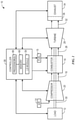
- FIG. 1 is a block diagram of an embodiment of a gas turbine system 10.
- the gas turbine system 10 may be part of a combined cycle system and/or combined with other gas turbine systems 10 to power one or more loads 12.
- the gas turbine system 10 is generally configured to drive the load 12 by combusting a mixture of compressed air and fuel 15 (e.g., natural gas, light or heavy distillate oil, naphtha, crude oil, residual oil, or syngas).
- the combustion is performed within a combustor 16, which may include one or more combustion chambers.
- Air 14 goes into an air intake at the compressor 20, is filtered, and is compressed in the compressor 20 via one or more compression stages.
- the air 14 is injected into the compressor 20 through a compressed air stream 18.
- the compressed air stream 18 is mixed with fuel 15.
- ignition may occur.
- the ignition produces hot combustion gases 26 that power the gas turbine system 10.
- the hot combustion gases 26 flow through a turbine 28 with one or more compression stages that drives the load 12 via a shaft 30.
- the combustion gases 26 may apply motive forces (e.g., via convection, expansion, and the like) to turbine rotor blades within the turbine 28 to rotate the shaft 30.
- the hot combustion gases 26 may force turbine blades in the turbine 28 to rotate the shaft 30 along an axis of the gas turbine system 10.
- the drive shaft 30 may be connected to various components of the gas turbine system 10, including the compressor 20 or the load 12.
- the drive shaft 30 may connect the turbine 28 to the compressor 20 to form a rotor.
- the compressor 20 may include compressor blades coupled to the drive shaft 30.
- rotation of turbine blades in the turbine 28 may cause the drive shaft 30 connecting the turbine 28 to the compressor 20 to rotate the compressor blades within the compressor 20.
- This rotation of compressor blades in the compressor 20 causes the compressor 20 to compress air 14 to generate the compressed air stream 18.
- the compressed air stream 18 is then fed to the combustor 16 and mixed with other combustion components.
- the shaft 30 may drive the compressor 20 in addition to or in lieu of the load 12.
- the load 12 may be a generator of the GTG. Additionally or alternatively, the load 12 may include a propeller, a transmission, or a drive system, among others.
- a stream of exhaust gas 32 may be provided to an exhaust section 34, where the exhaust gas 32 may be cooled or further processed.
- the exhaust section 34 may include a catalyst section 36 which includes a carbon monoxide (CO) catalyst, a NOx catalyst, an unburned hydrocarbon catalyst, and/or any similar metal-based catalyst (e.g., platinum-based catalysts).
- the catalyst section 36 may include a NOx catalyst that is configured to destroy NOx gases within the stream of exhaust gas 32 or a CO catalyst. The stream of exhaust gas 32 may then exit the exhaust section 34.
- gas turbine system 10 includes a controller 38.
- the controller 38 may include one or more processors 66 and memory 68, which may be used collectively to support an operating system, software applications and systems, and so forth, useful in implementing the techniques described herein.
- the controller 38 may include code or instructions stored in a non-transitory machine-readable medium (e.g., memory 68) and executed, for example, by the one or more processors 66 that may be included in the controller 38.
- the processor(s) 66 may receive parameters of operation from the various components (e.g., via one or more sensors) of the gas turbine system 10 including a shaft rotation speed, a frequency of electric power generated by the gas turbine system in a generator driven by the shaft 30, a voltage of the generated electric power, a demand from one or more load(s) 12, or other suitable parameters. In some embodiments, some parameters are measured directly while other parameters are determined indirectly from other measurements. For example, in certain embodiments, the controller 38 may utilize an algorithmic model or look-up table (e.g., stored in memory) to derive various parameters. The various parameters may include an operating speed of the shaft 30 or a connected GTG using electrical parameters.
- the electrical parameters may include a frequency or voltage of the electric power generated by the generator (e.g., the load 12). Further, the controller 38 may monitor operation of various parts of the gas turbine system 10. The monitored parameters may be used to control (e.g., adjust) operating parameters of one or more aspects of the gas turbine system 10.
- the controller 38 includes a load sharing (LS) module 39 that may monitor and analyze the shared operational data (such as online/offline status, output power, frequency, or voltage, and the like) from the other online power generation systems (e.g., gas turbine generators) existing on the same power grid as the gas turbine system 10. Based on the monitoring and analysis, the load sharing module 39 may determine a suitable control mode (e.g., droop speed control mode) and/or an appropriate set point (e.g., frequency or voltage) that may contribute to stable operation of the gas turbine system 10 and/or connected grid(s). The load sharing module 39 may then cause the controller 38 to select the determined control mode and/or set point for the gas turbine system 10.
- a suitable control mode e.g., droop speed control mode
- an appropriate set point e.g., frequency or voltage
- the controller 38 may receive the shared operational data from controllers of other power generation systems within multiple power systems (e.g., a set of gas turbine systems).
- the load sharing module 39 may include a physical circuit or may be at least partially embodied using the instructions stored in the memory 68 and running on the processor 66 of the controller 38.
- Load sharing may be defined as a proportional division of the total load (e.g., in kilo-Watt (kW) or kilo-Volt-Ampere-Reactive (KVAR)) between multiple power generation systems on a power grid.
- load sharing may be defined as a proportional division of the total load (e.g., in kilo-Watt (kW) or kilo-Volt-Ampere-Reactive (KVAR)) between multiple power generation systems on a power grid.
- KVAR kilo-Volt-Ampere-Reactive
- the other online GTGs may receive the offline signal through intercommunications, causing the controller(s) to calculate feasible new load distributions among the online GTGs, and increase the power output proportionally if the calculated new load distribution does not exceed a power rating of the online GTGs within the group. Additionally or alternatively, the controller(s) may invoke backup GTG(s) to share the load if the calculated new load distribution exceeds the power rating(s) of one or more online GTGs within the group.
- Load sharing may be used by a power grid with multiple power generation systems and various loads to avoid overloading and/or stability problems.
- the load sharing module 39 monitors the data from each of the fleet members even without a centralized controller and determines an appropriate way to contribute to a stable operation.
- the control mechanism described herein provides a distributed control system.
- the controller(s) e.g., the controller 38
- the controller(s) of individual power generation system may make adjustment(s) based on the information provided by the other power generation systems.
- Such control mechanism enables flexible operations of the multiple power systems. For example, operations of one or more power generation systems (e.g., gas turbine system 10) may be adjusted to fit particular demands of gas turbines or site operations under normal and/or abnormal conditions, such as adjusting start or shutdown sequences and/or tying breaker operations.
- the load sharing module 39 may be preinstalled in the controller 38 during manufacturing of the gas turbine system 10, or may be post-installed in a controller of an existing power generation system (e.g., a backup gas turbine system for the multiple power systems) as a retrofit kit and/or software update.
- implementation of the load sharing module 39 may involve no extra instrumentation than the already existing in a power generation system, enabling the any respective controllers 38 of power generation systems to perform the techniques discussed herein (e.g., with a software update).
- the distributed power generation systems may use one of the following modes of operation: stand-alone operation, parallel operation with connection to a utility grid, and island operation.
- Each operation mode may be associated with specific controls for gas turbines (e.g., gas turbine fuel control) and/or for power generators (e.g., generator excitation control) within the power grid.
- FIG. 2 depicts a power grid system 100 including a multiple gas turbine generators (GTGs) and respective GTG controllers.
- GTGs gas turbine generators
- Each of the GTGs may operate in a specific mode (stand-alone, parallel or island) depending on power grid configurations, loads, electrical switch (or breaker) states, etc. All three modes of operation are possible due to opening/closing certain electrical switches in the configuration of the power grid system 100.
- the power grid system 100 may include a main grid 160 (e.g., a utility grid), a local grid 150, and a power generator grid 140.
- the power generator grid 140 may include multiple GTGs 102, 112, 122, and 132, and respective GTG controllers 104, 114, 124, and 134. Any number (e.g., all) of the GTG controller 104, 114, 124, and 134 may include the load sharing module 39 as described in FIG. 1 .
- the power grid system 100 may include an interconnection data bus 170 that is used to handle communications among the GTG controllers 104, 114, 124, and 134.
- Various electrical switches 106, 116, 126, 136, 152, and 162 may be used to toggle connections in the power grid system 100.
- a GTG is not connected with other GTGs and/or the main grid 160.
- the GTG 102 operates in a stand-alone operation.
- the GTG 102 supplies power to connected loads on the local grid 150.
- a GTG working alone may be an emergency GTG when the local grid 150 loses power from one or more GTGs assigned to the local grid 150.
- the GTG 102 may start providing power for the local grid 150, which lost power from an assigned group of GTGs (e.g., GTGs 122 and 132).
- the stand-alone operation may include features such as controlling gas turbine fuel (e.g. the fuel 15 in FIG. 1 ) supply to raise/lower the output of the GTG 102, controlling excitation current to raise/lower the voltage output of the GTG 102, and other power management related procedures (e.g., keeping bus frequency and voltage constant for certain control modes), etc.
- the total loads on the local grid 150 determines the GTG 102 output power.
- the GTGs 102, 112, 122, and 132 operate in parallel to provide power to the main grid 160 and to the local grid 150.
- the main grid 160 may be considered an infinite bus.
- the GTGs 102, 112, 122 and 132 enter into the parallel operation.
- the GTGs 102, 112, 122 and 132 supply power to loads on the local grid 150 and/or the main grid 160.
- GTGs working in parallel operation may be organized into one or more subgroups of GTGs in a power plant.
- the GTGs 102 and 112 may form a subgroup A
- the GTGs 122 and 132 may form another subgroup B in the power plant.
- the two subgroups may work together to provide power for the local grid 150 and the main grid 160 or work when at least one of the subgroups are offline (e.g., due to maintenance).
- the parallel operation may include features such as controlling a gas turbine fuel supply to raise/lower active power of the GTGs 102, 112, 122, and 132, controlling excitation current to raise/lower the reactive power of the GTGs 102, 112, 122, and 132, controlling the difference between total power plant loads and GTG output power, and other power management related procedures (e.g., keeping power constant), etc.
- the main grid 160 determines the operation parameters such as the frequency output, voltage output, and speed.
- a GTG (e.g., GTGs 102, 112, 122, and 132) is connected with other GTGs, but the GTG is decoupled from the main grid 160.
- the GTGs 102, 112, and 122 operate in an island operation.
- the GTGs 102, 112, and 122 supply power to all connected loads on the local grid 150.
- a group of GTGs working in the island operation may supply power to an isolated system such as a ship, an offshore drilling platform, or an oil production field in a desert.
- the GTG 102 and 112 may form a set of GTGs in a local power plant on an offshore drilling platform to provide power for the local grid 150 that may include all electrical devices/machines/equipment on the offshore drilling platform.
- At least one GTG e.g., GTG 122
- the island operation may include features such as controlling the gas turbine fuel to raise/lower the GTGs active power and bus frequency, controlling the excitation current to raise/lower the GTGs reactive power and bus voltage, and other power management related procedures (e.g., keeping bus frequency and voltage constant while sharing the load proportionally or cost-efficiently among the operating GTGs), etc.
- the total loads on the local grid 150 may determine the sum of the power to be generated using operating GTGs.
- the interconnection data bus 170 is used to handle communications among the GTGs 102, 112, 122, and 132 via GTG controllers 104, 114, 124, and 134.
- the interconnection data bus 170 may include multiple cables/wires (such as coax signal cables, Ethernet cables, and the like) and/or wireless connections, which carry signals containing information related to load sharing using any suitable communication protocol for communicating between controllers 38 of the GTGs 102, 112, 122, and 132.
- the load sharing information may include identification information for respective GTG or GTG controller ID, online/offline operating status information of respective GTGs, power output information for the respective GTGs, GTG configuration information (e.g., maximum power output), and the like.
- the interconnection data bus 170 serves as a common highway for communications through which the GTGs 102, 112, 122, and 132 share statuses and relevant information with the others via GTG controllers 104, 114, 124, and 134.
- the controller 38 in each of the GTGs 102, 112, 122, and 132 may use one or more processors 66 to receive transmitted signals from the interconnection data bus 170 and store received information in the memory 68.
- the controller 38 of GTG may use the load sharing module 39 to monitor and analyze the operational data from the other online GTGs on the same grid and determine a control mode (e.g., droop mode, or isochronous mode) that may contribute to a stable operation of the entire grid.
- the load sharing module 39 may then cause the controller 38 to select the determined control mode for the specific GTG.
- the controller 38 may use the load sharing module 39 to monitor the operational data from the other GTGs to evaluate/verify performance of the group of operating GTGs.
- Each operation mode (e.g., stand-alone, parallel or island) of a power generation system on the power grid system 100 may be associated with specific control mode(s) for a group of GTGs within the power grid 100.
- specific control mode(s) for a group of GTGs within the power grid 100 may be associated with specific control mode(s) for a group of GTGs within the power grid 100.
- using the stand-alone load sharing module 39 in a control mechanism enables flexible operations of a group of GTGs.
- the flexible operations may include droop speed control mode for GTGs, isochronous speed control mode for GTGs, and/or other power control methods to accommodate different island topologies and events transitions, such as GTGs and/or other relevant units coupling to or decoupling from the power grid 100).
- Controlling power and speed for a group of GTGs relies on a coordinated effort based on a power demand on the group of GTGs, a number of GTGs available, parallel or island operation with particular topologies, and/or other relevant information especially during transient conditions and islanding events. Without coordination multiple GTGs operating in parallel may be subjected to unstable operations, for example, over-speed, losing speed reference, erratic power fluctuations, etc. Such unstable operations may cause unexpected power outages and/or lead to possible damage to GTGs or units on the power grid 100.
- FIG. 3 is a graph plotting active power 202 v. frequency 204 for an isochronous speed control mode that may be used by the multiple GTGs of FIG. 2 .
- the frequency (in Hz) is directly related to the speed (in RPM).
- a frequency line 220 of a GTG returns to an original set point line 210 (e.g., 50 Hz) after a load has been applied or rejected.
- the isochronous speed control mode may be used when a GTG is in stand-alone operation, or the GTG is the largest (in power) unit in multiple GTGs (e.g., in the island operation).
- the energy generated by the prime mover e.g., the gas turbine 28 in the gas turbine system 10.
- an instant load increase e.g. when a new load is added into an existing power grid
- an instant load decrease may cause a transient frequency increase, but because the energy is quickly regulated for the prime mover in the isochronous speed control mode, the frequency remains at or quickly returns to a set point.
- an instant load decreases e.g. when an existing load is removed from an existing power grid
- the frequency is maintained at or quickly returned to the set point.
- a GTG maintains a relatively constant speed regardless of the load changes.
- Certain issue(s) may arise when multiple GTGs in the isochronous speed control mode are operating on the same grid and the load changes frequently.
- the controller 38 may cause a speed governor of a prime mover (e.g., the gas turbine 28) to adjust the gas turbine fuel supply (e.g., fuel 15) to lower the speed.
- the controller 38 may cause the speed governor of the prime mover to at least partially open the gas turbine fuel supply to raise the speed. Therefore, the power grid may experience relatively small but frequent fluctuations of frequency as the load changes frequently.
- FIG. 4 is a graph plotting active power 202 v. frequency 204 for a droop speed control mode that may be used by the multiple GTGs of FIG. 2 .
- the frequency line 220 of a GTG decreases by a fixed percentage when the GTG is loaded from no-load (0%) to full load (100%).
- the fixed percentage e.g., 4%) may be predetermined based on the power grid configuration and the power rating of a GTG assigned to the power grid.
- An operator or a power management system may adjust the speed set point depending on operational parameters.
- the droop speed control mode may provide a stable working point for each load in case of the parallel operation in connection with the main grid 160.
- the droop speed control mode may be used by AC electrical power generators to reduce a power output of a GTG as the line frequency increases.
- the droop speed control may be implemented by using the speed governor of a prime mover (e.g., the gas turbine 28) driving a synchronous GTG (e.g., the GTG 102, 112, 122, or 132) connected to a power grid (e.g., the power grid 100). It works by controlling the rate of power produced by the prime mover according to the grid frequency.
- the droop speed control mode enables synchronous GTGs to run in parallel so that loads may be shared among GTGs with the same or similar droop line(s) or curve(s).
- droop curves used by a group of GTGs on an electrical power grid may be nonlinear or may be different from each other. For example, droop curves may be adjusted by operators in proportion to their power rating. Because the droop speed control mode accommodates changes in frequency, it enables multiple GTGs to work in tandem by dividing loads in proportion to their power. The droop speed control mode may be suitable when employed on power grids with multiple GTGs and/or when dealing with loads with higher degrees of power variance.
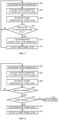
- FIG. 5 is a flow chart depicting a load sharing process for the power grid system 100 of FIG. 2 when a GTG in the power grid system 100 is brought online or offline.
- the GTG 102, GTG 112 and GTG 122 are in parallel serving the local grid 150.
- the local grid 150 has a total load (e.g., 600 kW), the GTG 102, GTG 112 and GTG122 may have power ratings (e.g., 400 kW, 200 kW, and 200 kW respectively).
- the power outputs of the GTG 102, GTG 112 and GTG 122 may be set to respective outputs (e.g., 300 kW, 150 kW, and 150 kW).
- the GTG 102, GTG 112 and GTG 122 may be driven to the same percentage (75%) load to reach load balancing.
- the GTG controller 104 may determine power generated (block 402) on GTG 102 (300 kW)
- the GTG controller 104 may publish power generated to other GTG controllers (block 404) such as GTG controller 114 and GTG controller 124.
- the publication is made through the interconnection data bus 170.
- the GTG controller 114 and GTG controller 124 may determine the power generated on GTG 112 and GTG 122 respectively (e.g., 150 kW and 150 kW) and publish the power generated via the interconnection data bus 170.
- the GTG controller 104 may retrieve the power generated by other GTGs (block 406) such as the GTG 112 and GTG 122.
- the GTG controller 104 determines whether an indication of an online/offline GTG has been received (block 408) is received.
- the indication may be a signal from another controller indicating that a GTG corresponding to the other controller is going or has gone offline. Additionally or alternatively, the indication may include receiving no communications from the other controller for a period longer than a threshold duration, and/or lower power generated by an amount indicating that a GTG has gone offline. In the event that no indication is received, the GTG controller 104 restarts the load sharing process at block 402.
- a GTG e.g., GTG 122
- a respective electrical switch e.g., electrical switch 126
- the GTG controller 104 and/or the GTG controller 114 receives the indication of an offline GTG. If the remaining GTGs (e.g., GTGs 102 and 112) are able to meet power demand of the local grid 150 that has a total load (e.g., 600 kW), the GTG controller 104 and the GTG controller 114 may determine new power level to be generated (block 410). For example, the GTG controller 104 and the GTG controller 114 may determine the power generated on GTG 102 and GTG 112 respectively (e.g., 400 kW and 200 kW).
- the GTG 102 and GTG 112 may receive instructions from the GTG controller 104 and the GTG controller 114 respectively to increase the power output to compensate the power supply loss due to the offline GTG 122.
- the instructions may cause the GTG 102 and GTG 112 to output new power levels (block 412).
- the GTG 102 and GTG 112 may operate at new power levels (e.g., 400 kW and 200 kW) to meet power demand of the local grid 150.
- the GTG controller 104 and the GTG controller 114 may instruct the GTG 102 and GTG 112 to go offline because the total load on the local grid 150 is exceeding a total capacity of remaining GTGs.
- FIG. 6 is a flow chart depicting a load sharing process for the power grid system 100 of FIG. 2 when an electrical switch changes state.
- an event of the state changing may occur when a GTG is brought online or offline from operation by an operator via a switchboard, or when the electrical switch is tripped due to excessive electricity flowing through the electrical switch.
- the electrical switch state changing event may be reported to a power management system in the power grid system 100 where the electrical switch is installed.
- the power management system may publish the electrical switch state changing event to relevant power units (e.g., GTGs 102, 112, 122, and 132 of FIG.
- the communication devices e.g., the GTG controller 104, 114, 124, and 134 to receive the published event from the power management system directly, or receive shared information related to the published event from the other power units via intercommunication (e.g., using the interconnection data bus 170).
- the first three blocks 402, 404, and 406 of FIG. 6 are the same as FIG. 5 .
- the GTG 102 may determine power generated (block 402), publish power generated to other GTG controller(s) (block 404), and retrieve power generated by other GTG(s) (block 406). If an electrical switch (e.g., electrical switch 162) is closed, a mode of operation may change.
- the GTG controller 104 may determine whether a state changing event has occurred (block 508).
- the GTG controller 104 may determine whether the state change corresponds to a change of mode at operation to make a change (block 510).
- change of power grid configuration may correspond to change between modes (e.g., isochronous mode v. droop mode).
- the GTG 102 was connected to the local grid 150 with the other GTGs such as GTG 112 and GTG 122, forming an isolated system.
- the GTG 102, GTG 112, and GTG 122 work in the island operation to supply power to all connected loads on the local grid 150.
- the GTG 102 may be selected to operate in isochronous speed control mode to maintain a constant speed (frequency) regardless of the load changes on the local grid 150 (e.g., an oil field isolated from the nearby utility grid).
- the GTG controller 104 may monitor and analyze relevant information whether to switch the speed control mode of the GTG 102.
- the relevant information may include the frequency and voltage of the main grid 160, the load changing in the main grid 160 and/or the local grid 150, the power generated by other online GTGs including GTG 112 and GTG 122, and the like.
- the load sharing module 39 may determine a new suitable control mode that will contribute to a stable operation of the main grid 160.
- the load sharing module 39 may cause the GTG controller 104 to switch mode for the GTG 102 (block 512). For instance, the control mode of the GTG 102 may be switched from previous isochronous speed control mode to droop speed control mode so that the speed will decrease by a fixed percentage as previously discussed.
- the load sharing module 39 may determine a new power level (block 514) based on the load (on the main grid 160 and/or the local grid 150) and power output from the other GTGs (e.g., GTGs 112 and 122).
- the load sharing module 39 may cause the GTG controller 104 to change the set point of the GTG 102 to output at new power level to accommodate load changes in the power grid and/or power output changes for the GTGs (block 515).
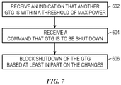
- FIG. 7 is a flow chart depicting a load sharing process for the power grid system 100 of FIG. 2 when a potential shut down situation may occur.
- the GTG 102 and GTG 112 may form a subgroup A and the GTG 122 and GTG 132 may form a subgroup B in the power grid system 100 of FIG. 2 .
- Each of the subgroups, and/or the power grid system 100 may perform coordinated operations.
- the GTGs 102, 112, 122 and 132 may provide power to meet a demand of the local grid 150, and/or the main grid 160.
- an electrical switch e.g., electrical switch 1266 is tripped so that a GTG goes offline.
- Remaining GTG(s) in the subgroup or in the power grid system 100 may receive an instruction to increase the power output to compensate the power supply loss due to the offline GTG.
- the instruction may cause the remaining GTG(s) be left to meet a demand over their power ratings (e.g., 200 kW) but within the limit of maximum power (e.g., 220 kW). However, the remaining GTG(s) may not be recommended to operate within a threshold of maximum power (e.g., 95% of maximum power) for certain amount of time.
- a respective GTG controller may receive an indication that another GTG (e.g., GTG 132) is within an impermissible/undesirable threshold of maximum power (block 602). The indication may also indicate that the other GTG will go offline after certain amount of time. Furthermore, the GTG controller may receive a command that a yet another GTG (GTG 102) is to be shut down (block 604) because the total load (e.g., 630 kW) on the local grid 150 is exceeding the total capacity of remaining GTGs (e.g., GTGs 102 and 112).
- the total load e.g., 630 kW
- the GTG controller 104 may determine to increase the power output of online GTG(s) other than the other GTG (GTG 132) (e.g., from 70% to 78.75% of the power rating(s)). Accordingly, the other GTG controller (GTG controller 134) may determine to decrease the power output (e.g., from 105% to 78.75% of the power rating) so that the projected offline situation will not occur. Furthermore, the GTG controller 104 may prevent shutdown of the GTG 102 based on at least in part on the changes (block 606). For example, maintenance may be delayed and/or shutdown conditions may change due to power production adjustment over the interconnection data bus 170. The GTG controller 104 may generate a waring and send the warning to an operator to indicate that the shutdown of the GTG 102 may be prevented.
- the technologies described in present disclosure may be applicable to a variety of power generation systems (gas turbine generators, steam turbine generators, hydroelectric turbine generators, and the like).
- the load sharing module provides solutions for different load sharing scenarios, such as load sharing in isochronous mode, load sharing on islands that may include separable islands, load sharing in parallel mode when frequent load changes occurred, etc. Independent operation may be achieved as no master controller (centralized controller) is implemented and the GTG controllers (equipped with the load sharing module) may determine an appropriate way (e.g., a speed control mode) to contribute to stable operation based on the information provided by the others generators.
- the load sharing module enables flexible operation for a set of generators, which may be adjusted to fit particular needs of site operations in normal or abnormal conditions.
- the GTG controller may instruct a corresponding GTG to maintain a mode in which the corresponding GTG is currently operating.
- the load set point and other operation preference e.g., operation mode
- suitable device(s) such as a third-party controller.
Landscapes
- Engineering & Computer Science (AREA)
- Power Engineering (AREA)
- Mechanical Engineering (AREA)
- General Engineering & Computer Science (AREA)
- Supply And Distribution Of Alternating Current (AREA)
- Control Of Eletrric Generators (AREA)
Abstract
Description
- The subject matter disclosed herein relates generally to a module for load-sharing in a power generation system. Specifically, the module is used to maintain a stable operation of a group of electrical power generators in different load sharing scenarios.
- Large industrial facilities, such as power plants, offshore drilling platforms, and oil rigs, may use multiple generators operating in a parallel configuration to maintain reliable electrical power supplies. To ensure power generation system stability, load sharing is used to distribute and share the loads evenly throughout the generators in the fleet. A centralized controller may be used to manage the load sharing and other parallel tasks. However, when the centralized controller is offline due to technical or environmental problems (e.g., extreme weather events), the parallel tasks may be inhibited, resulting in unevenly distributed loads among the generators and/or unstable power generation.
- A summary of certain embodiments disclosed herein is set forth below. It should be understood that these aspects are presented merely to provide the reader with a brief summary of these certain embodiments and that these aspects are not intended to limit the scope of this disclosure. Indeed, this disclosure may encompass a variety of aspects that may not be set forth below.
- In a first embodiment, a method is provided. In accordance with this method, a controller of a gas-turbine generator (GTG) receives an indication of a status of another GTG over an interconnection bus. Based on the status of the other GTG, the controller determines a power level to be generated by the GTG and drives the GTG to output the power level.
- In a second embodiment, a non-transitory, computer-readable medium storing instructions is provided. The instructions, when executed by one or more processors, cause the one or more processors to receive, at a controller of a gas-turbine generator (GTG), an indication of power generated in a set of GTGs (including the GTG) that are part of a power network. The instructions also cause the one or more processors to receive, at the controller, an indication of a status change of a switch in the power network, in which the status change includes a toggle of a connection of one of the set of GTGs to the power network or a connection of the power network to a grid, and the indication is received over an interconnect bus interconnecting a set of controllers corresponding to the set of GTGs. The instructions also cause the one or more processors to determine, based on the status of the switch and the power generated, whether a change in power generated by the power network is to occur. The instructions also cause the one or more processors to drive, using the controller, the GTG based at least in part on the determination of whether to change the power generated.
- In a third embodiment, a system is provided. The system includes a controller that includes a memory storing instructions and a processor that is used to execute the instructions. The instructions, when executed by the processor, cause the processor to control power generation in a gas-turbine generator (GTG) in a power network that includes a set of GTGs. Specifically, the instructions, when executed by the processor, cause the processor to: receive an indication that another GTG of the set of GTGs is within a threshold of a maximum power generation of the other GTG, in which the indication is received over an interconnect bus that interconnects the controllers of the set of GTGs. The instructions also cause the processor to receive a command that the GTG is to be shut down and, based on the indication, prevent the shutdown of the GTG and send a warning to an operator.
- These and other features, aspects, and advantages of the present invention will become better understood when the following detailed description is read with reference to the accompanying drawings in which like characters represent like parts throughout the drawings, wherein:
-
FIG. 1 is a block diagram of a gas turbine engine configured to power a load, in accordance with an embodiment; -
FIG. 2 is a block diagram depicting a power grid system including multiple gas turbine generators with controllers equipped with load sharing modules, in accordance with an embodiment; -
FIG. 3 is a frequency vs. power plot showing an isochronous speed control method that may be used by the multiple gas turbine generators ofFIG. 2 , in accordance with an embodiment; -
FIG. 4 is a frequency vs. power plot showing a droop speed control method that may be used by the multiple gas turbine generators ofFIG. 2 , in accordance with an embodiment; -
FIG. 5 is a flow chart depicting a load sharing process on one of the multiple gas turbine generators ofFIG. 2 when another generator in the fleet is brought online or offline, in accordance with an embodiment; -
FIG. 6 is a flow chart depicting a load sharing process on one of the multiple gas turbine generators ofFIG. 2 when an electrical switch changes state, in accordance with an embodiment; and -
FIG. 7 is a flow chart depicting a load sharing process on one of the multiple gas turbine generators ofFIG. 2 when a potential shut down situation may occur, in accordance with an embodiment. - One or more specific embodiments will be described below. In an effort to provide a concise description of these embodiments, not all features of an actual implementation are described in the specification. It should be appreciated that in the development of any such actual implementation, as in any engineering or design project, numerous implementation-specific decisions must be made to achieve the developers' specific goals, such as compliance with system-related and business-related constraints, which may vary from one implementation to another. Moreover, it should be appreciated that such a development effort might be complex and time consuming, but would nevertheless be a routine undertaking of design, fabrication, and manufacture for those of ordinary skill having the benefit of this disclosure.
- When introducing elements of various embodiments of the present disclosure, the articles "a," "an," "the," and "said" are intended to mean that there are one or more of the elements. The terms "comprising," "including," and "having" are intended to be inclusive and mean that there may be additional elements other than the listed elements. Furthermore, any numerical examples in the following discussion are intended to be nonlimiting, and thus additional numerical values, ranges, and percentages are within the scope of the disclosed embodiments.
- Power generation systems are used to convert energy sources into electrical power. The energy sources may be hydraulic, coal, natural gas, crude oil, nuclear, solar, or wind energy. Gas turbine (also called combustion turbine) power plants run on natural gas or liquid fuels. Gas turbine generators (GTGs) provide operational flexibility. For instance, the gas turbine is a type of internal combustion engine designed to meet increases in power demand quickly.
- The main components in the GTG include an upstream rotating compressor(s), a combustor, downstream turbine(s) on the same shaft as the compressor(s), and a generator. Gas turbines are engines used for producing movement to turn electrical generators. The gas turbines are combustion engines that convert natural gas or liquid fuels to rotational mechanical energy, which further drives the generators to produce electrical energy. More specifically, the gas turbines draw in air, compress the intaken air, mix the air with fuel, distribute the air-fuel mixture into a combustor where combustions (triggered by ignitions) of the air-fuel mixture create hot pressurized gases to cause turbine blades to spin. The spinning of the turbine blades drives the generator that is connected (e.g., via a shaft) to the turbine blades to convert rotational energy into electricity.
- Industrial facilities, such as factories, electric power plants, offshore oil platform or drilling rigs, may use multiple GTGs operating in a parallel configuration to maintain reliable electrical power supply levels. Systems using multiple GTGs may synchronize the GTGs where the GTGs are operating in parallel. As part of the synchronization, load sharing distributes and shares the load (e.g., proportionally/evenly) throughout the GTGs in the fleet. At least some of the GTGs in the fleet may have independent controllers communicating with a centralized controller (master controller). The master controller may manage the parallel tasks (including the load sharing) for the fleet. When the master controller is offline due to technical/environmental problems (e.g., troubleshooting, maintenance, or extreme weather event), the parallel tasks may be switched to manual operations executed by onsite operator(s) (e.g., using a switchboard configuration) or to a backup centralized controller, if available. However, using manual operations or backup centralized controller may increase the operational complexity that may result in reduced efficiency and/or increased cost.
- The subject matter discussed herein relates to a load sharing modules that may be used to maintain stable operations of a group of GTGs in different load sharing scenarios. The reusable and flexible load sharing modules, located in one or more of the GTGs, are configured to select a control mode (such as a droop mode or an isochronous mode) of the respective GTG. The control modes are based on a status and/or other relevant information shared through communications among the GTGs in the group via an interconnection data bus. Therefore, a centralized controller or hierarchical control system for parallel tasks such as load sharing may be omitted and/or operations may continue when communications with the centralized controller fails. Additionally or alternatively, the load set point and other operation preference may be set by a third-party controller.
- Turning now to the drawings,
FIG. 1 is a block diagram of an embodiment of agas turbine system 10. As an example, thegas turbine system 10 may be part of a combined cycle system and/or combined with othergas turbine systems 10 to power one ormore loads 12. Specifically, thegas turbine system 10 is generally configured to drive theload 12 by combusting a mixture of compressed air and fuel 15 (e.g., natural gas, light or heavy distillate oil, naphtha, crude oil, residual oil, or syngas). The combustion is performed within acombustor 16, which may include one or more combustion chambers.Air 14 goes into an air intake at thecompressor 20, is filtered, and is compressed in thecompressor 20 via one or more compression stages. - To begin the combustion process within the
combustor 16, theair 14 is injected into thecompressor 20 through acompressed air stream 18. Thecompressed air stream 18 is mixed withfuel 15. Using the mixture of thefuel 15 and theair 14, ignition may occur. The ignition produces hot combustion gases 26 that power thegas turbine system 10. More specifically, the hot combustion gases 26 flow through aturbine 28 with one or more compression stages that drives theload 12 via ashaft 30. For example, the combustion gases 26 may apply motive forces (e.g., via convection, expansion, and the like) to turbine rotor blades within theturbine 28 to rotate theshaft 30. In an example process, the hot combustion gases 26 may force turbine blades in theturbine 28 to rotate theshaft 30 along an axis of thegas turbine system 10. As illustrated, thedrive shaft 30 may be connected to various components of thegas turbine system 10, including thecompressor 20 or theload 12. - As previously noted, the
drive shaft 30 may connect theturbine 28 to thecompressor 20 to form a rotor. Thecompressor 20 may include compressor blades coupled to thedrive shaft 30. Thus, rotation of turbine blades in theturbine 28 may cause thedrive shaft 30 connecting theturbine 28 to thecompressor 20 to rotate the compressor blades within thecompressor 20. This rotation of compressor blades in thecompressor 20 causes thecompressor 20 to compressair 14 to generate thecompressed air stream 18. As previously noted, thecompressed air stream 18 is then fed to thecombustor 16 and mixed with other combustion components. Theshaft 30 may drive thecompressor 20 in addition to or in lieu of theload 12. As an example, theload 12 may be a generator of the GTG. Additionally or alternatively, theload 12 may include a propeller, a transmission, or a drive system, among others. - Once the
turbine 28 extracts work from the hot combustion gases 26, a stream ofexhaust gas 32 may be provided to anexhaust section 34, where theexhaust gas 32 may be cooled or further processed. For example, theexhaust section 34 may include acatalyst section 36 which includes a carbon monoxide (CO) catalyst, a NOx catalyst, an unburned hydrocarbon catalyst, and/or any similar metal-based catalyst (e.g., platinum-based catalysts). For example, in the illustrated embodiment, thecatalyst section 36 may include a NOx catalyst that is configured to destroy NOx gases within the stream ofexhaust gas 32 or a CO catalyst. The stream ofexhaust gas 32 may then exit theexhaust section 34. - As illustrated,
gas turbine system 10 includes acontroller 38. Thecontroller 38 may include one ormore processors 66 andmemory 68, which may be used collectively to support an operating system, software applications and systems, and so forth, useful in implementing the techniques described herein. Particularly, thecontroller 38 may include code or instructions stored in a non-transitory machine-readable medium (e.g., memory 68) and executed, for example, by the one ormore processors 66 that may be included in thecontroller 38. The processor(s) 66 may receive parameters of operation from the various components (e.g., via one or more sensors) of thegas turbine system 10 including a shaft rotation speed, a frequency of electric power generated by the gas turbine system in a generator driven by theshaft 30, a voltage of the generated electric power, a demand from one or more load(s) 12, or other suitable parameters. In some embodiments, some parameters are measured directly while other parameters are determined indirectly from other measurements. For example, in certain embodiments, thecontroller 38 may utilize an algorithmic model or look-up table (e.g., stored in memory) to derive various parameters. The various parameters may include an operating speed of theshaft 30 or a connected GTG using electrical parameters. The electrical parameters may include a frequency or voltage of the electric power generated by the generator (e.g., the load 12). Further, thecontroller 38 may monitor operation of various parts of thegas turbine system 10. The monitored parameters may be used to control (e.g., adjust) operating parameters of one or more aspects of thegas turbine system 10. - As illustrated, the
controller 38 includes a load sharing (LS)module 39 that may monitor and analyze the shared operational data (such as online/offline status, output power, frequency, or voltage, and the like) from the other online power generation systems (e.g., gas turbine generators) existing on the same power grid as thegas turbine system 10. Based on the monitoring and analysis, theload sharing module 39 may determine a suitable control mode (e.g., droop speed control mode) and/or an appropriate set point (e.g., frequency or voltage) that may contribute to stable operation of thegas turbine system 10 and/or connected grid(s). Theload sharing module 39 may then cause thecontroller 38 to select the determined control mode and/or set point for thegas turbine system 10. - The
controller 38 may receive the shared operational data from controllers of other power generation systems within multiple power systems (e.g., a set of gas turbine systems). Theload sharing module 39 may include a physical circuit or may be at least partially embodied using the instructions stored in thememory 68 and running on theprocessor 66 of thecontroller 38. - Load sharing may be defined as a proportional division of the total load (e.g., in kilo-Watt (kW) or kilo-Volt-Ampere-Reactive (KVAR)) between multiple power generation systems on a power grid. Through intercommunications (e.g., via the controllers 38) among group(s) of GTGs serving a power grid, coordinated adjustments may be made to distribute and share the load of the power grid proportionally throughout the online GTGs. For example, when the load of the power grid increases, at least some of the online GTGs may increase power output with equal percentage to accept the load change. For example, a group of GTGs may operate in parallel to provide power for an offshore drilling platform. When one of the group of GTGs is offline, the other online GTGs may receive the offline signal through intercommunications, causing the controller(s) to calculate feasible new load distributions among the online GTGs, and increase the power output proportionally if the calculated new load distribution does not exceed a power rating of the online GTGs within the group. Additionally or alternatively, the controller(s) may invoke backup GTG(s) to share the load if the calculated new load distribution exceeds the power rating(s) of one or more online GTGs within the group.
- Load sharing may be used by a power grid with multiple power generation systems and various loads to avoid overloading and/or stability problems. As previously noted, for tasks (such as load sharing) within the multiple power systems , the
load sharing module 39 monitors the data from each of the fleet members even without a centralized controller and determines an appropriate way to contribute to a stable operation. In other words, the control mechanism described herein provides a distributed control system. The controller(s) (e.g., the controller 38) of two or more individual power generation systems receives an operating status and other relevant information from other power generation systems. The controller(s) of individual power generation system may make adjustment(s) based on the information provided by the other power generation systems. Such control mechanism enables flexible operations of the multiple power systems. For example, operations of one or more power generation systems (e.g., gas turbine system 10) may be adjusted to fit particular demands of gas turbines or site operations under normal and/or abnormal conditions, such as adjusting start or shutdown sequences and/or tying breaker operations. - As a reusable and flexible module, the
load sharing module 39 may be preinstalled in thecontroller 38 during manufacturing of thegas turbine system 10, or may be post-installed in a controller of an existing power generation system (e.g., a backup gas turbine system for the multiple power systems) as a retrofit kit and/or software update. In one or more embodiments, implementation of theload sharing module 39 may involve no extra instrumentation than the already existing in a power generation system, enabling the anyrespective controllers 38 of power generation systems to perform the techniques discussed herein (e.g., with a software update). - The distributed power generation systems may use one of the following modes of operation: stand-alone operation, parallel operation with connection to a utility grid, and island operation. Each operation mode may be associated with specific controls for gas turbines (e.g., gas turbine fuel control) and/or for power generators (e.g., generator excitation control) within the power grid.
- With the preceding in mind,
FIG. 2 depicts apower grid system 100 including a multiple gas turbine generators (GTGs) and respective GTG controllers. Each of the GTGs may operate in a specific mode (stand-alone, parallel or island) depending on power grid configurations, loads, electrical switch (or breaker) states, etc. All three modes of operation are possible due to opening/closing certain electrical switches in the configuration of thepower grid system 100. - As illustrated, the
power grid system 100 may include a main grid 160 (e.g., a utility grid), alocal grid 150, and apower generator grid 140. Thepower generator grid 140 may includemultiple GTGs respective GTG controllers GTG controller load sharing module 39 as described inFIG. 1 . Thepower grid system 100 may include aninterconnection data bus 170 that is used to handle communications among theGTG controllers electrical switches power grid system 100. - In stand-alone operation, a GTG is not connected with other GTGs and/or the
main grid 160. For example, as illustrated inFIG. 2 , when theelectrical switches switches GTG 102 operates in a stand-alone operation. As an isolated power generation unit, theGTG 102 supplies power to connected loads on thelocal grid 150. - In one or more embodiments, a GTG working alone may be an emergency GTG when the
local grid 150 loses power from one or more GTGs assigned to thelocal grid 150. For instance, in the example described above, theGTG 102 may start providing power for thelocal grid 150, which lost power from an assigned group of GTGs (e.g.,GTGs 122 and 132). The stand-alone operation may include features such as controlling gas turbine fuel (e.g. thefuel 15 inFIG. 1 ) supply to raise/lower the output of theGTG 102, controlling excitation current to raise/lower the voltage output of theGTG 102, and other power management related procedures (e.g., keeping bus frequency and voltage constant for certain control modes), etc. In stand-alone operation, the total loads on thelocal grid 150 determines theGTG 102 output power. - In a parallel operation mode, the
GTGs main grid 160 and to thelocal grid 150. In some embodiments, themain grid 160 may be considered an infinite bus. For example, as illustrated inFIG. 2 , when all theelectrical switches GTGs GTGs local grid 150 and/or themain grid 160. - In one or more embodiments, GTGs working in parallel operation may be organized into one or more subgroups of GTGs in a power plant. For instance, in the example described above, the
GTGs GTGs local grid 150 and themain grid 160 or work when at least one of the subgroups are offline (e.g., due to maintenance). The parallel operation may include features such as controlling a gas turbine fuel supply to raise/lower active power of theGTGs GTGs main grid 160 determines the operation parameters such as the frequency output, voltage output, and speed. - In an island operation, a GTG (e.g.,
GTGs main grid 160. For example, as illustrated inFIG. 2 , when theelectrical switches electrical switches GTGs GTGs local grid 150. - In one or more embodiments, a group of GTGs working in the island operation may supply power to an isolated system such as a ship, an offshore drilling platform, or an oil production field in a desert. For instance, in the example described above, the
GTG local grid 150 that may include all electrical devices/machines/equipment on the offshore drilling platform. At least one GTG (e.g., GTG 122) may serve as a backup GTG for emergency use only when one or more of the other GTGs (e.g.,GTG 102 and 112) is offline). The island operation may include features such as controlling the gas turbine fuel to raise/lower the GTGs active power and bus frequency, controlling the excitation current to raise/lower the GTGs reactive power and bus voltage, and other power management related procedures (e.g., keeping bus frequency and voltage constant while sharing the load proportionally or cost-efficiently among the operating GTGs), etc. In island operation, the total loads on thelocal grid 150 may determine the sum of the power to be generated using operating GTGs. - To share information among a group of operating GTGs (either in the parallel operation or in island operation), the
interconnection data bus 170 is used to handle communications among theGTGs GTG controllers interconnection data bus 170 may include multiple cables/wires (such as coax signal cables, Ethernet cables, and the like) and/or wireless connections, which carry signals containing information related to load sharing using any suitable communication protocol for communicating betweencontrollers 38 of theGTGs interconnection data bus 170 serves as a common highway for communications through which theGTGs GTG controllers - The
controller 38 in each of theGTGs more processors 66 to receive transmitted signals from theinterconnection data bus 170 and store received information in thememory 68. Thecontroller 38 of GTG may use theload sharing module 39 to monitor and analyze the operational data from the other online GTGs on the same grid and determine a control mode (e.g., droop mode, or isochronous mode) that may contribute to a stable operation of the entire grid. Theload sharing module 39 may then cause thecontroller 38 to select the determined control mode for the specific GTG. Furthermore, after the new control mode or new set point is applied to the specific GTG, thecontroller 38 may use theload sharing module 39 to monitor the operational data from the other GTGs to evaluate/verify performance of the group of operating GTGs. - Each operation mode (e.g., stand-alone, parallel or island) of a power generation system on the
power grid system 100 may be associated with specific control mode(s) for a group of GTGs within thepower grid 100. As described previously, using the stand-aloneload sharing module 39 in a control mechanism enables flexible operations of a group of GTGs. The flexible operations may include droop speed control mode for GTGs, isochronous speed control mode for GTGs, and/or other power control methods to accommodate different island topologies and events transitions, such as GTGs and/or other relevant units coupling to or decoupling from the power grid 100). Controlling power and speed for a group of GTGs relies on a coordinated effort based on a power demand on the group of GTGs, a number of GTGs available, parallel or island operation with particular topologies, and/or other relevant information especially during transient conditions and islanding events. Without coordination multiple GTGs operating in parallel may be subjected to unstable operations, for example, over-speed, losing speed reference, erratic power fluctuations, etc. Such unstable operations may cause unexpected power outages and/or lead to possible damage to GTGs or units on thepower grid 100. -
FIG. 3 is a graph plottingactive power 202v. frequency 204 for an isochronous speed control mode that may be used by the multiple GTGs ofFIG. 2 . For alternating current (AC) generators (including GTGs), the frequency (in Hz) is directly related to the speed (in RPM). As illustrated, in the isochronous speed control mode, afrequency line 220 of a GTG returns to an original set point line 210 (e.g., 50 Hz) after a load has been applied or rejected. - The isochronous speed control mode may be used when a GTG is in stand-alone operation, or the GTG is the largest (in power) unit in multiple GTGs (e.g., in the island operation). In the isochronous speed control mode, the energy generated by the prime mover (e.g., the
gas turbine 28 in the gas turbine system 10) is regulated tightly in reaction to load changes. For example, an instant load increase (e.g. when a new load is added into an existing power grid) may cause a transient frequency decrease, but because energy is quickly regulated for the prime mover in the isochronous speed control mode, the frequency remains at or quickly returns to a set point. Likewise, an instant load decreases (e.g. when an existing load is removed from an existing power grid) may cause a transient frequency increase, but because the energy is quickly regulated for the prime mover in the isochronous speed control mode, the frequency is maintained at or quickly returned to the set point. - In other words, in the isochronous speed control mode, a GTG maintains a relatively constant speed regardless of the load changes. Certain issue(s) (such as instability) may arise when multiple GTGs in the isochronous speed control mode are operating on the same grid and the load changes frequently. For example, in
FIG. 2 , when theelectrical switches GTG main grid 160. Themain grid 160 may determine the frequency and voltage of the power generated by theGTG controller 38 may cause a speed governor of a prime mover (e.g., the gas turbine 28) to adjust the gas turbine fuel supply (e.g., fuel 15) to lower the speed. Similarly, when the speed set point is slightly higher, thecontroller 38 may cause the speed governor of the prime mover to at least partially open the gas turbine fuel supply to raise the speed. Therefore, the power grid may experience relatively small but frequent fluctuations of frequency as the load changes frequently. - When multiple GTGs are operating in parallel, a droop speed control mode may be used to avoid issues such as the fluctuations of frequency as load changes.
FIG. 4 is a graph plottingactive power 202v. frequency 204 for a droop speed control mode that may be used by the multiple GTGs ofFIG. 2 . As illustrated, in the droop speed control mode, thefrequency line 220 of a GTG decreases by a fixed percentage when the GTG is loaded from no-load (0%) to full load (100%). The fixed percentage (e.g., 4%) may be predetermined based on the power grid configuration and the power rating of a GTG assigned to the power grid. An operator or a power management system may adjust the speed set point depending on operational parameters. The droop speed control mode may provide a stable working point for each load in case of the parallel operation in connection with themain grid 160. - The droop speed control mode may be used by AC electrical power generators to reduce a power output of a GTG as the line frequency increases. The droop speed control may be implemented by using the speed governor of a prime mover (e.g., the gas turbine 28) driving a synchronous GTG (e.g., the
GTG -
FIG. 5 is a flow chart depicting a load sharing process for thepower grid system 100 ofFIG. 2 when a GTG in thepower grid system 100 is brought online or offline. For example, inFIG. 2 , when theelectrical switches electrical switches GTG 102,GTG 112 andGTG 122 are in parallel serving thelocal grid 150. Thelocal grid 150 has a total load (e.g., 600 kW), theGTG 102,GTG 112 and GTG122 may have power ratings (e.g., 400 kW, 200 kW, and 200 kW respectively). The total load of thelocal grid 150 is a percentage (e.g., 75%) of the total power ratings combined fromGTG 102,GTG 112, and GTG 122 (e.g., 400 + 200 + 200 = 800 kW). As described previously, to achieve a load balancing operation, the power outputs of theGTG 102,GTG 112 andGTG 122 may be set to respective outputs (e.g., 300 kW, 150 kW, and 150 kW). In other words, theGTG 102,GTG 112 andGTG 122 may be driven to the same percentage (75%) load to reach load balancing. The GTG controller 104 (with the load sharing module 39) may determine power generated (block 402) on GTG 102 (300 kW) TheGTG controller 104 may publish power generated to other GTG controllers (block 404) such asGTG controller 114 and GTG controller 124. The publication is made through theinterconnection data bus 170. TheGTG controller 114 and GTG controller 124 may determine the power generated onGTG 112 andGTG 122 respectively (e.g., 150 kW and 150 kW) and publish the power generated via theinterconnection data bus 170. TheGTG controller 104 may retrieve the power generated by other GTGs (block 406) such as theGTG 112 andGTG 122. TheGTG controller 104 determines whether an indication of an online/offline GTG has been received (block 408) is received. For instance, the indication may be a signal from another controller indicating that a GTG corresponding to the other controller is going or has gone offline. Additionally or alternatively, the indication may include receiving no communications from the other controller for a period longer than a threshold duration, and/or lower power generated by an amount indicating that a GTG has gone offline. In the event that no indication is received, theGTG controller 104 restarts the load sharing process atblock 402. - If at a particular moment, a GTG (e.g., GTG 122) is brought offline by opening a respective electrical switch (e.g., electrical switch 126), the
GTG controller 104 and/or theGTG controller 114 receives the indication of an offline GTG. If the remaining GTGs (e.g.,GTGs 102 and 112) are able to meet power demand of thelocal grid 150 that has a total load (e.g., 600 kW), theGTG controller 104 and theGTG controller 114 may determine new power level to be generated (block 410). For example, theGTG controller 104 and theGTG controller 114 may determine the power generated onGTG 102 andGTG 112 respectively (e.g., 400 kW and 200 kW). TheGTG 102 andGTG 112 may receive instructions from theGTG controller 104 and theGTG controller 114 respectively to increase the power output to compensate the power supply loss due to theoffline GTG 122. The instructions may cause theGTG 102 andGTG 112 to output new power levels (block 412). For example, theGTG 102 andGTG 112 may operate at new power levels (e.g., 400 kW and 200 kW) to meet power demand of thelocal grid 150. If the remaining GTGs (e.g.,GTGs 102 and 112) are unable to meet power demand of thelocal grid 150 that has a total load (e.g., 700 kW), theGTG controller 104 and theGTG controller 114 may instruct theGTG 102 andGTG 112 to go offline because the total load on thelocal grid 150 is exceeding a total capacity of remaining GTGs. -
FIG. 6 is a flow chart depicting a load sharing process for thepower grid system 100 ofFIG. 2 when an electrical switch changes state. For example, an event of the state changing (from OFF to ON state, or vice versa) may occur when a GTG is brought online or offline from operation by an operator via a switchboard, or when the electrical switch is tripped due to excessive electricity flowing through the electrical switch. The electrical switch state changing event may be reported to a power management system in thepower grid system 100 where the electrical switch is installed. The power management system may publish the electrical switch state changing event to relevant power units (e.g.,GTGs FIG. 2 ), which are equipped with communication devices (e.g., theGTG controller - The first three
blocks FIG. 6 are the same asFIG. 5 . Using the example described previously, when theelectrical switches FIG. 2 are open, and theelectrical switches GTG 102,GTG 112 andGTG 122 are in parallel serving thelocal grid 150. TheGTG 102 may determine power generated (block 402), publish power generated to other GTG controller(s) (block 404), and retrieve power generated by other GTG(s) (block 406). If an electrical switch (e.g., electrical switch 162) is closed, a mode of operation may change. TheGTG controller 104 may determine whether a state changing event has occurred (block 508). TheGTG controller 104 may determine whether the state change corresponds to a change of mode at operation to make a change (block 510). For example, change of power grid configuration may correspond to change between modes (e.g., isochronous mode v. droop mode). For example, before theswitch 162 is closed, theGTG 102 was connected to thelocal grid 150 with the other GTGs such asGTG 112 andGTG 122, forming an isolated system. As discussed previously, in the isolated system, theGTG 102,GTG 112, andGTG 122 work in the island operation to supply power to all connected loads on thelocal grid 150. Accordingly, theGTG 102 may be selected to operate in isochronous speed control mode to maintain a constant speed (frequency) regardless of the load changes on the local grid 150 (e.g., an oil field isolated from the nearby utility grid). - After connecting to the
main grid 160, theGTG controller 104 may monitor and analyze relevant information whether to switch the speed control mode of theGTG 102. The relevant information may include the frequency and voltage of themain grid 160, the load changing in themain grid 160 and/or thelocal grid 150, the power generated by other onlineGTGs including GTG 112 andGTG 122, and the like. As mentioned previously, when the GTGs are in parallel operation with themain grid 160, and the load changes frequently, continuing working in the isochronous speed control mode may lead to instability issues as the GTGs in isochronous speed control mode will tend to maintain a constant speed regardless of the load changes. Based on the monitoring and analysis, theload sharing module 39 may determine a new suitable control mode that will contribute to a stable operation of themain grid 160. Theload sharing module 39 may cause theGTG controller 104 to switch mode for the GTG 102 (block 512). For instance, the control mode of theGTG 102 may be switched from previous isochronous speed control mode to droop speed control mode so that the speed will decrease by a fixed percentage as previously discussed. - If the
load sharing module 39 determines no change is to be made (block 510), theload sharing module 39 may determine a new power level (block 514) based on the load (on themain grid 160 and/or the local grid 150) and power output from the other GTGs (e.g.,GTGs 112 and 122). Theload sharing module 39 may cause theGTG controller 104 to change the set point of theGTG 102 to output at new power level to accommodate load changes in the power grid and/or power output changes for the GTGs (block 515). -
FIG. 7 is a flow chart depicting a load sharing process for thepower grid system 100 ofFIG. 2 when a potential shut down situation may occur. As previously discussed, theGTG 102 andGTG 112 may form a subgroup A and theGTG 122 andGTG 132 may form a subgroup B in thepower grid system 100 ofFIG. 2 . Each of the subgroups, and/or thepower grid system 100 may perform coordinated operations. TheGTGs local grid 150, and/or themain grid 160. - If at a particular moment, an electrical switch (e.g., electrical switch 126) is tripped so that a GTG goes offline. Remaining GTG(s) in the subgroup or in the
power grid system 100 may receive an instruction to increase the power output to compensate the power supply loss due to the offline GTG. The instruction may cause the remaining GTG(s) be left to meet a demand over their power ratings (e.g., 200 kW) but within the limit of maximum power (e.g., 220 kW). However, the remaining GTG(s) may not be recommended to operate within a threshold of maximum power (e.g., 95% of maximum power) for certain amount of time. A respective GTG controller (e.g., GTG controller 104) may receive an indication that another GTG (e.g., GTG 132) is within an impermissible/undesirable threshold of maximum power (block 602). The indication may also indicate that the other GTG will go offline after certain amount of time. Furthermore, the GTG controller may receive a command that a yet another GTG (GTG 102) is to be shut down (block 604) because the total load (e.g., 630 kW) on thelocal grid 150 is exceeding the total capacity of remaining GTGs (e.g.,GTGs 102 and 112). By using theload sharing module 39 to analyze the indication that the other GTG is within a threshold of maximum power and other relevant information, theGTG controller 104 may determine to increase the power output of online GTG(s) other than the other GTG (GTG 132) (e.g., from 70% to 78.75% of the power rating(s)). Accordingly, the other GTG controller (GTG controller 134) may determine to decrease the power output (e.g., from 105% to 78.75% of the power rating) so that the projected offline situation will not occur. Furthermore, theGTG controller 104 may prevent shutdown of theGTG 102 based on at least in part on the changes (block 606). For example, maintenance may be delayed and/or shutdown conditions may change due to power production adjustment over theinterconnection data bus 170. TheGTG controller 104 may generate a waring and send the warning to an operator to indicate that the shutdown of theGTG 102 may be prevented. - The technologies described in present disclosure may be applicable to a variety of power generation systems (gas turbine generators, steam turbine generators, hydroelectric turbine generators, and the like). The load sharing module provides solutions for different load sharing scenarios, such as load sharing in isochronous mode, load sharing on islands that may include separable islands, load sharing in parallel mode when frequent load changes occurred, etc. Independent operation may be achieved as no master controller (centralized controller) is implemented and the GTG controllers (equipped with the load sharing module) may determine an appropriate way (e.g., a speed control mode) to contribute to stable operation based on the information provided by the others generators. The load sharing module enables flexible operation for a set of generators, which may be adjusted to fit particular needs of site operations in normal or abnormal conditions. For instance, when a GTG controller loses communication from other GTG controller(s), the GTG controller may instruct a corresponding GTG to maintain a mode in which the corresponding GTG is currently operating. Additionally or alternatively, the load set point and other operation preference (e.g., operation mode) may be set by customers via suitable device(s) such as a third-party controller.
- This written description uses examples to disclose the invention, including the best mode, and also to enable any person skilled in the art to practice the invention, including making and using any devices or systems and performing any incorporated methods. The patentable scope of the invention is defined by the claims, and may include other examples that occur to those skilled in the art. Such other examples are intended to be within the scope of the claims if they have structural elements that do not differ from the literal language of the claims, or if they include equivalent structural elements with insubstantial differences from the literal languages of the claims.
Claims (14)
- A method, comprising:receiving, at a controller (104) of a gas-turbine generator (GTG) (102), an indication of a status of another GTG (122) over an interconnect bus (170);based on the status of the other GTG (122), determining (410), using the controller (104), a power level to be generated by the GTG (102); anddriving (412), using the controller (104), the GTG (102) to output the power level.
- The method of claim 1, wherein the indication comprises a lack of an update from another controller (124) of the other GTG (122) over the interconnect bus (170) for a threshold time.
- The method of claim 1, wherein the indication comprises a message from another controller (124) of the other GTG (122) over the interconnect bus (170).
- The method of claim 1, wherein the interconnect bus (170) comprises a wireless connection for the controller (104).
- The method of claim 1, wherein the status comprises an offline status of the other GTG (122), and the power level is lower than an initial power level.
- The method of claim 1, wherein the status comprises an online status, and the power level is higher than an initial power level.
- The method of claim 1, comprising determining (402) a generated power for the GTG (102).
- The method of claim 7, comprising publishing (404) the generated power to the interconnect bus (170).
- The method of claim 8, comprising retrieving (406) power generated connected GTGs in a power network comprising the GTG (102) and the other GTG (122).
- The method of claim 1, comprising determining (408) that the GTG (122) was scheduled to go offline before receiving the indication.
- The method of claim 10, comprising determining that remaining online GTGs in a plurality of connected GTGs including the GTG 102 and the other GTG (112) cannot meet a threshold power for the connected GTGs with the GTG (122) offline.
- The method of claim 11, wherein determining the power level comprises stopping (606) the scheduled shutdown of the GTG (102) from occurring in response to determining that the remaining online GTGs cannot meet the threshold power.
- A system, comprising:a controller (104) comprising a memory (68) storing instructions and a processor (66) configured to execute the instructions to cause the processor (66) to control power generation in a gas-turbine generator (GTG) (102) in a power network comprising a plurality of GTGs, wherein the instructions, when executed by the processor (66), is configured to cause the processor (66) to:receive (602) an indication that another GTG (132) of the plurality of GTGs is within a threshold of a maximum power generation of the other GTG (132), wherein the indication is received over an interconnect bus (170) that interconnects the controllers of the plurality of GTGs;receive (604) a command that the GTG (102) is to be shut down; andbased on the indication, prevent (606) the shutdown of the GTG (102) and send a warning to an operator.
- The system of claim 13, wherein the shutdown corresponds to a scheduled maintenance or offline period for the GTG (102).
Applications Claiming Priority (1)
| Application Number | Priority Date | Filing Date | Title |
|---|---|---|---|
| US17/010,310 US12218510B2 (en) | 2020-09-02 | 2020-09-02 | Load-sharing with interconnected power generation |
Publications (2)
| Publication Number | Publication Date |
|---|---|
| EP3965250A1 true EP3965250A1 (en) | 2022-03-09 |
| EP3965250B1 EP3965250B1 (en) | 2026-07-01 |
Family
ID=77640331
Family Applications (1)
| Application Number | Title | Priority Date | Filing Date |
|---|---|---|---|
| EP21191572.3A Active EP3965250B1 (en) | 2020-09-02 | 2021-08-16 | LOAD DISTRIBUTION WITH COMBINED ENERGY GENERATION |
Country Status (4)
| Country | Link |
|---|---|
| US (2) | US12218510B2 (en) |
| EP (1) | EP3965250B1 (en) |
| JP (1) | JP7814864B2 (en) |
| CN (1) | CN114204604A (en) |
Families Citing this family (3)
| Publication number | Priority date | Publication date | Assignee | Title |
|---|---|---|---|---|
| US20220101219A1 (en) * | 2020-09-28 | 2022-03-31 | Solarlytics, Inc. | System and method for optimizing energy obtained from renewable sources |
| WO2022210768A1 (en) * | 2021-03-31 | 2022-10-06 | 株式会社ラプラス・システム | Control terminal of power generation system and control program therefor, and production method for power generation system |
| US11619145B2 (en) * | 2021-05-06 | 2023-04-04 | General Electric Company | Coordinated combined cycle power plant response for block loading in grid restoration |
Citations (5)
| Publication number | Priority date | Publication date | Assignee | Title |
|---|---|---|---|---|
| US5973481A (en) * | 1996-03-13 | 1999-10-26 | National Bank Of Alaska | Control system and circuits for distributed electrical power generating stations |
| EP1798836A1 (en) * | 2005-12-16 | 2007-06-20 | General Electric Company | Power balancing of multiple synchronized generators |
| US20130342020A1 (en) * | 2012-06-25 | 2013-12-26 | Honeywell International Inc. | Fuel efficiency optimization for microgrid systems employing multiple generators |
| US20140062199A1 (en) * | 2012-06-07 | 2014-03-06 | Grupo Guascor S.L. | Load sharing system |
| US20170271872A1 (en) * | 2016-03-16 | 2017-09-21 | Schweitzer Engineering Laboratories, Inc. | Decentralized Generator Control |
Family Cites Families (19)
| Publication number | Priority date | Publication date | Assignee | Title |
|---|---|---|---|---|
| US3902076A (en) * | 1974-08-12 | 1975-08-26 | Barber Colman Co | Generator monitoring circuit |
| US6639331B2 (en) * | 2001-11-30 | 2003-10-28 | Onan Corporation | Parallel generator power system |
| US7457688B2 (en) | 2006-09-19 | 2008-11-25 | General Electric Company | Method and system for detection and transfer to electrical island operation |
| US7619324B2 (en) * | 2007-01-29 | 2009-11-17 | Caterpillar Inc. | Power system with multiple generator sets |
| US8106633B2 (en) * | 2008-12-18 | 2012-01-31 | Caterpillar Inc. | Generator set control system |
| US8912672B2 (en) * | 2009-05-20 | 2014-12-16 | Cummins Power Generator IP, Inc. | Control of an engine-driven generator to address transients of an electrical power grid connected thereto |
| JP5295155B2 (en) * | 2010-03-15 | 2013-09-18 | 中国電力株式会社 | Power supply system control method and power supply system |
| US8818565B2 (en) | 2011-08-31 | 2014-08-26 | General Electric Company | Systems and methods for performing islanding operations |
| US8987931B2 (en) * | 2011-11-01 | 2015-03-24 | Renewable Power Holdings, Inc. | Flexible energy balancing system |
| US9306417B2 (en) * | 2011-12-05 | 2016-04-05 | Utc Fire & Security Americas Corporation, Inc. | Load-sharing and boost voltage for notification appliance circuits |
| JP2013258874A (en) * | 2012-06-14 | 2013-12-26 | Mitsubishi Heavy Ind Ltd | Generator controller and generator control method |
| US9520819B2 (en) | 2014-02-28 | 2016-12-13 | General Electric Company | System and method for controlling a power generation system based on a detected islanding event |
| JP6517494B2 (en) * | 2014-10-30 | 2019-05-22 | 株式会社東芝 | Power converter, control method and computer program |
| EP3254370A4 (en) | 2015-02-06 | 2018-08-15 | United Technologies Corporation | Grid connected and islanded modes seamless transition |
| US9932907B2 (en) * | 2015-03-03 | 2018-04-03 | General Electric Company | Methods and systems for enhancing control of power plant generating units |
| US20170242081A1 (en) * | 2016-02-24 | 2017-08-24 | General Electric Company | System and method for optimization of recommended service intervals |
| US10833507B2 (en) | 2016-11-29 | 2020-11-10 | Schweitzer Engineering Laboratories, Inc. | Island detection and control of a microgrid |
| US10243371B2 (en) * | 2016-12-15 | 2019-03-26 | Caterpillar Inc. | System, apparatus, and method for controlling load sharing of generator sets |
| US10476417B2 (en) * | 2017-08-11 | 2019-11-12 | Rolls-Royce North American Technologies Inc. | Gas turbine generator torque DC to DC converter control system |
-
2020
- 2020-09-02 US US17/010,310 patent/US12218510B2/en active Active
-
2021
- 2021-08-16 EP EP21191572.3A patent/EP3965250B1/en active Active
- 2021-08-24 CN CN202110977989.1A patent/CN114204604A/en active Pending
- 2021-08-30 JP JP2021139494A patent/JP7814864B2/en active Active
-
2025
- 2025-01-02 US US19/007,922 patent/US20250132573A1/en active Pending
Patent Citations (5)
| Publication number | Priority date | Publication date | Assignee | Title |
|---|---|---|---|---|
| US5973481A (en) * | 1996-03-13 | 1999-10-26 | National Bank Of Alaska | Control system and circuits for distributed electrical power generating stations |
| EP1798836A1 (en) * | 2005-12-16 | 2007-06-20 | General Electric Company | Power balancing of multiple synchronized generators |
| US20140062199A1 (en) * | 2012-06-07 | 2014-03-06 | Grupo Guascor S.L. | Load sharing system |
| US20130342020A1 (en) * | 2012-06-25 | 2013-12-26 | Honeywell International Inc. | Fuel efficiency optimization for microgrid systems employing multiple generators |
| US20170271872A1 (en) * | 2016-03-16 | 2017-09-21 | Schweitzer Engineering Laboratories, Inc. | Decentralized Generator Control |
Non-Patent Citations (1)
| Title |
|---|
| AHMED MOUDUD ET AL: "Stability and Control Aspects of Microgrid Architectures-A Comprehensive Review", IEEE ACCESS, IEEE, USA, vol. 8, 6 August 2020 (2020-08-06), pages 144730 - 144766, XP011804797, DOI: 10.1109/ACCESS.2020.3014977 * |
Also Published As
| Publication number | Publication date |
|---|---|
| EP3965250B1 (en) | 2026-07-01 |
| JP2022042494A (en) | 2022-03-14 |
| US20220069587A1 (en) | 2022-03-03 |
| US20250132573A1 (en) | 2025-04-24 |
| US12218510B2 (en) | 2025-02-04 |
| JP7814864B2 (en) | 2026-02-17 |
| CN114204604A (en) | 2022-03-18 |
Similar Documents
| Publication | Publication Date | Title |
|---|---|---|
| US20250132573A1 (en) | Load-sharing with interconnected power generation | |
| US8463451B2 (en) | Automatic primary frequency response contribution monitoring system and method | |
| US9388753B2 (en) | Generator control having power grid communications | |
| US20220364546A1 (en) | Providing auxiliary power using offshore wind turbines | |
| US20090160187A1 (en) | Control system and method for operating a wind farm in a balanced state | |
| CN103620904B (en) | Parallel Operation Control method between variety classes Blast Furnace Top Gas Recovery Turbine Unit (TRT) and control system | |
| Ilyushin et al. | Approaches to organization of emergency control at isolated operation of energy areas with distributed generation | |
| CN108512246B (en) | Control method based on oil injection quantity-frequency-active power collaborative MIMO control system | |
| CN110658399A (en) | Power generation ship power supply system test optimization platform | |
| Kole | A review and study on advanced control and automation functions and future control for a modern combined cycle power plant | |
| Kalogiannis et al. | Impact of high level penetration of wind turbines on power system transient stability | |
| Svendsen et al. | Operational planning and power management system for offshore platform with wind energy supply–impacts on CO2 reduction and power quality | |
| Jerković et al. | Stability testing of a small biogas plant in an electric power system | |
| EP4510406A2 (en) | Method and system for emergency backup power | |
| Cui et al. | A coordinated regulation control for primary frequency of wind power and advanced adiabatic compressed air energy storage | |
| Ilyushin et al. | How the design of generator sets for distributed generation affects the design of emergency controls | |
| JP7430167B2 (en) | How to restore power to regional microgrids | |
| Markowski et al. | Evaluation of the operating parameters of a kinetic energy storage for the support of a generating set operating in island mode | |
| Yang et al. | Optimization of Battery Configuration by Embedding Differentiated Joint Frequency Modulation Simulation Model | |
| Qingxin et al. | Frequency Stability Characteristics and Parameters Optimization of Isolated Grids with High Proportion of New Energy and Small Hydropower | |
| KR102181774B1 (en) | Power plant linked multi-purpose energy storage system and method for operating the same | |
| Guo | Coal-based Synchronous Condenser | |
| Quinonez-Varela et al. | Electrical integration assessment of wind turbines into industrial power systems: the case of a mining unit | |
| Yang et al. | Coordinated Optimal Configuration Method of Wind Power Load Shedding Rate and Energy Storage Aiming at Active Frequency Support | |
| Li et al. | Algorithm Research on Minimum Inertia Demand of New Energy Sending Grid Generating Units Considering System Transient Stability |
Legal Events
| Date | Code | Title | Description |
|---|---|---|---|
| PUAI | Public reference made under article 153(3) epc to a published international application that has entered the european phase |
Free format text: ORIGINAL CODE: 0009012 |
|
| STAA | Information on the status of an ep patent application or granted ep patent |
Free format text: STATUS: THE APPLICATION HAS BEEN PUBLISHED |
|
| AK | Designated contracting states |
Kind code of ref document: A1 Designated state(s): AL AT BE BG CH CY CZ DE DK EE ES FI FR GB GR HR HU IE IS IT LI LT LU LV MC MK MT NL NO PL PT RO RS SE SI SK SM TR |
|
| STAA | Information on the status of an ep patent application or granted ep patent |
Free format text: STATUS: REQUEST FOR EXAMINATION WAS MADE |
|
| 17P | Request for examination filed |
Effective date: 20220701 |
|
| RBV | Designated contracting states (corrected) |
Designated state(s): AL AT BE BG CH CY CZ DE DK EE ES FI FR GB GR HR HU IE IS IT LI LT LU LV MC MK MT NL NO PL PT RO RS SE SI SK SM TR |
|
| RAP1 | Party data changed (applicant data changed or rights of an application transferred) |
Owner name: GENERAL ELECTRIC TECHNOLOGY GMBH |
|
| STAA | Information on the status of an ep patent application or granted ep patent |
Free format text: STATUS: EXAMINATION IS IN PROGRESS |
|
| 17Q | First examination report despatched |
Effective date: 20250124 |
|
| RAP3 | Party data changed (applicant data changed or rights of an application transferred) |
Owner name: GE VERNOVA TECHNOLOGY GMBH |
|
| GRAP | Despatch of communication of intention to grant a patent |
Free format text: ORIGINAL CODE: EPIDOSNIGR1 |
|
| STAA | Information on the status of an ep patent application or granted ep patent |
Free format text: STATUS: GRANT OF PATENT IS INTENDED |
|
| INTG | Intention to grant announced |
Effective date: 20260331 |
|
| GRAS | Grant fee paid |
Free format text: ORIGINAL CODE: EPIDOSNIGR3 |
|
| GRAA | (expected) grant |
Free format text: ORIGINAL CODE: 0009210 |
|
| STAA | Information on the status of an ep patent application or granted ep patent |
Free format text: STATUS: THE PATENT HAS BEEN GRANTED |
|
| AK | Designated contracting states |
Kind code of ref document: B1 Designated state(s): AL AT BE BG CH CY CZ DE DK EE ES FI FR GB GR HR HU IE IS IT LI LT LU LV MC MK MT NL NO PL PT RO RS SE SI SK SM TR |
|
| REG | Reference to a national code |
Ref country code: CH Ref legal event code: F10 Free format text: ST27 STATUS EVENT CODE: U-0-0-F10-F00 (AS PROVIDED BY THE NATIONAL OFFICE) Effective date: 20260701 Ref country code: GB Ref legal event code: FG4D |
|
| REG | Reference to a national code |
Ref country code: DE Ref legal event code: R096 Ref document number: 602021056366 Country of ref document: DE |
|
| REG | Reference to a national code |
Ref country code: IE Ref legal event code: FG4D |
|
| P01 | Opt-out of the competence of the unified patent court (upc) registered |
Free format text: CASE NUMBER: UPC_APP_0019893_3965250/2026 Effective date: 20260630 |