EP3965234A1 - Positioning adapter for coaxial connector assembly - Google Patents
Positioning adapter for coaxial connector assembly Download PDFInfo
- Publication number
- EP3965234A1 EP3965234A1 EP21194320.4A EP21194320A EP3965234A1 EP 3965234 A1 EP3965234 A1 EP 3965234A1 EP 21194320 A EP21194320 A EP 21194320A EP 3965234 A1 EP3965234 A1 EP 3965234A1
- Authority
- EP
- European Patent Office
- Prior art keywords
- coaxial
- contact
- adapter
- connector assembly
- conductive shell
- Prior art date
- Legal status (The legal status is an assumption and is not a legal conclusion. Google has not performed a legal analysis and makes no representation as to the accuracy of the status listed.)
- Granted
Links
Images


Classifications
-
- H—ELECTRICITY
- H01—ELECTRIC ELEMENTS
- H01R—ELECTRICALLY-CONDUCTIVE CONNECTIONS; STRUCTURAL ASSOCIATIONS OF A PLURALITY OF MUTUALLY-INSULATED ELECTRICAL CONNECTING ELEMENTS; COUPLING DEVICES; CURRENT COLLECTORS
- H01R13/00—Details of coupling devices of the kinds covered by groups H01R12/70 or H01R24/00 - H01R33/00
- H01R13/40—Securing contact members in or to a base or case; Insulating of contact members
- H01R13/42—Securing in a demountable manner
- H01R13/426—Securing by a separate resilient retaining piece supported by base or case, e.g. collar or metal contact-retention clip
-
- H—ELECTRICITY
- H01—ELECTRIC ELEMENTS
- H01R—ELECTRICALLY-CONDUCTIVE CONNECTIONS; STRUCTURAL ASSOCIATIONS OF A PLURALITY OF MUTUALLY-INSULATED ELECTRICAL CONNECTING ELEMENTS; COUPLING DEVICES; CURRENT COLLECTORS
- H01R24/00—Two-part coupling devices, or either of their cooperating parts, characterised by their overall structure
- H01R24/38—Two-part coupling devices, or either of their cooperating parts, characterised by their overall structure having concentrically or coaxially arranged contacts
- H01R24/40—Two-part coupling devices, or either of their cooperating parts, characterised by their overall structure having concentrically or coaxially arranged contacts specially adapted for high frequency
- H01R24/52—Two-part coupling devices, or either of their cooperating parts, characterised by their overall structure having concentrically or coaxially arranged contacts specially adapted for high frequency mounted in or to a panel or structure
- H01R24/525—Outlets
-
- H—ELECTRICITY
- H01—ELECTRIC ELEMENTS
- H01R—ELECTRICALLY-CONDUCTIVE CONNECTIONS; STRUCTURAL ASSOCIATIONS OF A PLURALITY OF MUTUALLY-INSULATED ELECTRICAL CONNECTING ELEMENTS; COUPLING DEVICES; CURRENT COLLECTORS
- H01R24/00—Two-part coupling devices, or either of their cooperating parts, characterised by their overall structure
- H01R24/38—Two-part coupling devices, or either of their cooperating parts, characterised by their overall structure having concentrically or coaxially arranged contacts
- H01R24/40—Two-part coupling devices, or either of their cooperating parts, characterised by their overall structure having concentrically or coaxially arranged contacts specially adapted for high frequency
- H01R24/54—Intermediate parts, e.g. adapters, splitters or elbows
- H01R24/542—Adapters
-
- H—ELECTRICITY
- H01—ELECTRIC ELEMENTS
- H01R—ELECTRICALLY-CONDUCTIVE CONNECTIONS; STRUCTURAL ASSOCIATIONS OF A PLURALITY OF MUTUALLY-INSULATED ELECTRICAL CONNECTING ELEMENTS; COUPLING DEVICES; CURRENT COLLECTORS
- H01R13/00—Details of coupling devices of the kinds covered by groups H01R12/70 or H01R24/00 - H01R33/00
- H01R13/62—Means for facilitating engagement or disengagement of coupling parts or for holding them in engagement
- H01R13/629—Additional means for facilitating engagement or disengagement of coupling parts, e.g. aligning or guiding means, levers, gas pressure electrical locking indicators, manufacturing tolerances
- H01R13/631—Additional means for facilitating engagement or disengagement of coupling parts, e.g. aligning or guiding means, levers, gas pressure electrical locking indicators, manufacturing tolerances for engagement only
- H01R13/6315—Additional means for facilitating engagement or disengagement of coupling parts, e.g. aligning or guiding means, levers, gas pressure electrical locking indicators, manufacturing tolerances for engagement only allowing relative movement between coupling parts, e.g. floating connection
-
- H—ELECTRICITY
- H01—ELECTRIC ELEMENTS
- H01R—ELECTRICALLY-CONDUCTIVE CONNECTIONS; STRUCTURAL ASSOCIATIONS OF A PLURALITY OF MUTUALLY-INSULATED ELECTRICAL CONNECTING ELEMENTS; COUPLING DEVICES; CURRENT COLLECTORS
- H01R24/00—Two-part coupling devices, or either of their cooperating parts, characterised by their overall structure
- H01R24/38—Two-part coupling devices, or either of their cooperating parts, characterised by their overall structure having concentrically or coaxially arranged contacts
- H01R24/40—Two-part coupling devices, or either of their cooperating parts, characterised by their overall structure having concentrically or coaxially arranged contacts specially adapted for high frequency
- H01R24/52—Two-part coupling devices, or either of their cooperating parts, characterised by their overall structure having concentrically or coaxially arranged contacts specially adapted for high frequency mounted in or to a panel or structure
-
- H—ELECTRICITY
- H01—ELECTRIC ELEMENTS
- H01R—ELECTRICALLY-CONDUCTIVE CONNECTIONS; STRUCTURAL ASSOCIATIONS OF A PLURALITY OF MUTUALLY-INSULATED ELECTRICAL CONNECTING ELEMENTS; COUPLING DEVICES; CURRENT COLLECTORS
- H01R9/00—Structural associations of a plurality of mutually-insulated electrical connecting elements, e.g. terminal strips or terminal blocks; Terminals or binding posts mounted upon a base or in a case; Bases therefor
- H01R9/03—Connectors arranged to contact a plurality of the conductors of a multiconductor cable, e.g. tapping connections
- H01R9/05—Connectors arranged to contact a plurality of the conductors of a multiconductor cable, e.g. tapping connections for coaxial cables
-
- H—ELECTRICITY
- H05—ELECTRIC TECHNIQUES NOT OTHERWISE PROVIDED FOR
- H05K—PRINTED CIRCUITS; CASINGS OR CONSTRUCTIONAL DETAILS OF ELECTRIC APPARATUS; MANUFACTURE OF ASSEMBLAGES OF ELECTRICAL COMPONENTS
- H05K7/00—Constructional details common to different types of electric apparatus
- H05K7/14—Mounting supporting structure in casing or on frame or rack
- H05K7/1438—Back panels or connecting means therefor; Terminals; Coding means to avoid wrong insertion
- H05K7/1452—Mounting of connectors; Switching; Reinforcing of back panels
- H05K7/1454—Alignment mechanisms; Drawout cases
-
- H—ELECTRICITY
- H01—ELECTRIC ELEMENTS
- H01R—ELECTRICALLY-CONDUCTIVE CONNECTIONS; STRUCTURAL ASSOCIATIONS OF A PLURALITY OF MUTUALLY-INSULATED ELECTRICAL CONNECTING ELEMENTS; COUPLING DEVICES; CURRENT COLLECTORS
- H01R13/00—Details of coupling devices of the kinds covered by groups H01R12/70 or H01R24/00 - H01R33/00
- H01R13/02—Contact members
- H01R13/22—Contacts for co-operating by abutting
- H01R13/24—Contacts for co-operating by abutting resilient; resiliently-mounted
- H01R13/2407—Contacts for co-operating by abutting resilient; resiliently-mounted characterized by the resilient means
- H01R13/2421—Contacts for co-operating by abutting resilient; resiliently-mounted characterized by the resilient means using coil springs
-
- H—ELECTRICITY
- H01—ELECTRIC ELEMENTS
- H01R—ELECTRICALLY-CONDUCTIVE CONNECTIONS; STRUCTURAL ASSOCIATIONS OF A PLURALITY OF MUTUALLY-INSULATED ELECTRICAL CONNECTING ELEMENTS; COUPLING DEVICES; CURRENT COLLECTORS
- H01R2103/00—Two poles
Definitions
- Coaxial connectors are known for interconnecting various coaxial components, such as coaxial cables, circuit boards, and/or the like.
- Coaxial connectors include one or more coaxial contact pairs. Each coaxial contact pair includes a center contact and a conductive shell that is arranged coaxially with the center contact.
- Coaxial connectors often include an array of coaxial contacts.
- the coaxial connectors may be designed to receive first types of coaxial contacts, such as coaxial contacts having a first diameter.
- Other coaxial connectors may be designed to receive second types of coaxial contacts, such as coaxial contacts having a second diameter. It may be desirable to utilize different types of coaxial contacts in the same coaxial connector. However, redesign of the coaxial connectors to arrange the different diameter coaxial contacts in the connector body is costly.
- the solution is provided by a coaxial connector assembly.
- the coaxial connector assembly includes a connector module having a connector body that includes contact channels extending therethrough between a front side and a rear side of the connector body. The front side faces in a mating direction for mating with a mating connector assembly.
- the coaxial connector assembly includes coaxial contacts received in the corresponding contact channels. The coaxial contacts are terminated to ends of coaxial cables.
- Each coaxial contact has a center contact, a conductive shell coaxial with the center contact, and an insulator between the center contact and the conductive shell.
- the conductive shell has a retention feature.
- the coaxial connector assembly includes positioning adapters received in the corresponding contact channels.
- Each positioning adapter includes an adapter body forming an adapter bore extending between a front and a rear of the positioning adapter.
- the adapter bore receives the corresponding coaxial contact such that the adapter body surrounds the coaxial contact.
- the adapter body engages the retention feature to position the coaxial contact relative to the adapter body.
- the adapter body engages the connector body to position the coaxial contact in the contact cavity relative to the connector body.
- the contact channel may comprise at least one contact cavity.
- the connector body may have a shoulder for the adapter body to engage. A spring in the contact cavity may bias the adapter body to engage the shoulder.
- Embodiments set forth herein include coaxial connector assemblies and communication systems that include such coaxial connector assemblies.
- the communication system may include, for example, a circuit board that is secured to the coaxial connector assembly.
- the communication system is a backplane (or midplane) communication system.
- the terms backplane and midplane are used interchangeably and represent a system interface for multiple daughter card assemblies (e.g., line cards or switch cards).
- the communication system is a circuit board assembly (e.g., daughter card assembly).
- One or more embodiments permit utilization of different sized coaxial contacts within the coaxial connector assembly.
- One or more embodiments permit two different sized coaxial contacts to be loaded into the same diameter contact channels in the coaxial connector assembly.
- One or more embodiments permit a connector module of the connector assembly to float during a mating operation.
- One or more embodiments enable using a denser grouping of coaxial contacts by permitting the coaxial contacts to be rear-loaded into the connector module.
- the connector module is permitted to float and also enables rear-loading of coaxial contacts.
- a coaxial connector assembly in an embodiment, includes a connector module having a connector body that includes contact channels extending therethrough between a front side and a rear side of the connector body. The front side faces in a mating direction for mating with a mating connector assembly.
- the coaxial connector assembly includes coaxial contacts received in the corresponding contact channels. The coaxial contacts are terminated to ends of coaxial cables.
- Each coaxial contact has a center contact, a conductive shell coaxial with the center contact, and an insulator between the center contact and the conductive shell.
- the conductive shell has a retention feature.
- the coaxial connector assembly includes positioning adapters received in the corresponding contact channels.
- Each positioning adapter includes an adapter body forming an adapter bore extending between a front and a rear of the positioning adapter.
- the adapter bore receives the corresponding coaxial contact such that the adapter body surrounds the coaxial contact.
- the adapter body engages the retention feature to position the coaxial contact relative to the adapter body.
- the adapter body engages the connector body to position the coaxial contact in the contact cavity relative to the connector body.
- a coaxial connector assembly in another embodiment, includes a connector module having a connector body that includes first contact channels and second contact channels extending therethrough between a front side and a rear side of the connector body. The front side faces in a mating direction for mating with a mating connector assembly.
- the coaxial connector assembly includes first coaxial contacts received in the corresponding first contact channels. The first coaxial contacts are terminated to ends of first coaxial cables. Each first coaxial contact has a first center contact, a first conductive shell coaxial with the first center contact, and a first insulator between the first center contact and the first conductive shell.
- the first conductive shell has a retention feature.
- the coaxial connector assembly includes second coaxial contacts received in the corresponding second contact channels.
- the second coaxial contacts are terminated to ends of second coaxial cables.
- Each second coaxial contact has a second center contact, a second conductive shell coaxial with the second center contact, and a second insulator between the second center contact and the second conductive shell.
- the coaxial connector assembly includes positioning adapters coupled to the corresponding first coaxial contacts. The positioning adapters are received in the corresponding first contact channels.
- Each positioning adapter includes an adapter body forming an adapter bore extending between a front and a rear of the positioning adapter.
- the adapter bore receives the corresponding first coaxial contact such that the adapter body surrounds the first coaxial contact.
- the adapter body engages the retention feature to position the coaxial contact relative to the adapter body.
- the adapter body engages the connector body to position the coaxial contact in the contact cavity relative to the connector body.
- the first contact channels have equivalent dimensions as the second contact channels.
- the adapter bodies have substantially similar diameters as the second conductive shells.
- a coaxial contact assembly in another embodiment, includes a center contact having a mating end and a cable end. The cable end is configured to be terminated to a conductor of a coaxial cable.
- the coaxial contact assembly includes a conductive shell coaxial with the center contact. The conductive shell has a mating end and a cable end. The cable end is configured to be terminated to a cable shield of the coaxial cable.
- the conductive shell includes a shell bore receiving the center contact.
- the conductive shell has a retention feature.
- the coaxial contact assembly includes an insulator received in the shell bore between the center contact and the conductive shell.
- the coaxial contact assembly includes a positioning adapter configured to be received in a contact cavity of a connector module.
- the positioning adapter includes an adapter body forming an adapter bore extending between a front and a rear of the positioning adapter.
- the adapter bore receives the conductive shell such that the adapter body surrounds an exterior of the conductive shell.
- the adapter body engages the retention feature to position the conductive shell relative to the adapter body and position the conductive shell in the contact cavity.
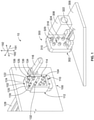
- Figure 1 illustrates a communication system 10 in accordance with an exemplary embodiment, showing a connector assembly 100 and a mating connector assembly 300 in an unmated state.
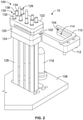
- Figure 2 is an exploded view of a portion of the communication system showing the connector assembly 100 in accordance with an exemplary embodiment.
- the connector assemblies 100, 300 are coaxial connector assemblies and may be referred to hereinafter as coaxial connector assemblies 100, 300.
- the communication system 10 may be provided with other types of connector assemblies, such as pin and socket connector assemblies, fiber optic connector assemblies, and the like.
- the connector assemblies 100, 300 are configured to be mated along a mating axis 191.
- the connector assemblies 100, 300 are oriented with respect to mutually perpendicular axes 191-193, which includes the mating axis 191, a first lateral axis 192, and a second lateral axis 193.
- the connector assemblies 100, 300 may be referred to more generally as a circuit board assemblies.
- the communication system 10 may be configured for radiofrequency (RF) applications.
- the communication system 10 and/or its components, such as the connector assembly 100 and/or 300 are configured to satisfy military and aerospace applications.
- the components of the communication system 10 may be configured to satisfy one or more industry or government standards, such as MIL-STD-348.
- the connector assemblies 100, 300 may form an interconnect between analog and digital sections of a radio.
- the connector assembly 300 may perform analog functions.
- the connector assembly 300 may be replaced with other connector assemblies that are configured to perform the same or different operations.
- the digital functions, including digital signal processing, may be performed by a communication component (not shown) that is coupled to the connector assembly 100.
- the other communication component may be another daughter card assembly (not shown).
- the communication system 10 and/or its components may be configured to satisfy one or more industry or government standards.
- embodiments may be configured to satisfy the VME International Trade Association (VITA) standards (e.g., VITA 48, VITA 67, et al.).
- VITA VME International Trade Association
- the communication system 10 and/or its components may have an operating speed that achieves 50 GHz or greater.
- the communication system 10 and/or its components may achieve an operating speed of 60 GHz or greater.
- embodiments may be configured for different standards and may be configured to operate at different speeds.
- embodiments may be configured to operate within the range of DC to 60.0 GHz.
- the connector assembly 300 is a daughter card assembly having a connector module 302.
- the connector module 302 may be mounted to a substrate 306, which may be a circuit card, such as a daughter card.
- the connector assembly 300 includes a guide module 308 mounted to the substrate 306 proximate to the connector module 302.
- the guide module 308 is used to guide mating with the connector assembly 100.
- the guide module 308 includes an opening configured to receive an alignment pin. The opening may be chamfered or have a lead-in. Other types of guide features may be used in alternative embodiments, such as a guide post.
- the connector module 302 is a right-angle connector module having the substrate 306 oriented perpendicular to the mating face of the connector module 302.
- the substrate 306 is oriented perpendicular to the substrate of the connector assembly 100.
- the connector module 302 may be a mezzanine connector having the substrate 306 oriented parallel to the mating face and parallel to the substrate of the connector assembly 100.
- the connector module 302 includes a connector body 310 holding cable assemblies 320.
- Each cable assembly 320 includes a cable 322 and a contact 324 terminated to the end of the cable 322, and may be routed to a remote location.
- the cables 322 may be terminated to the substrate 306, such as via substrate contacts.
- the contacts 324 may be terminated to the substrate 306 rather than having cables 322.
- the connector body 310 includes a plurality of contact channels (not shown) receiving corresponding cable assemblies 320.
- the connector body 310 includes alignment features 318 for aligning the connector module 302 with the connector assembly 100 during mating. In the illustrated embodiment, the alignment features 318 are openings. Other types of alignment features may be provided in alternative embodiments. The alignment features 318 may be arranged to provide keyed mating with the connector assembly 100.
- the contact 324 is a coaxial contact; however, other types of contacts may be provided in alternative embodiments, such as pin contacts, socket contacts, fiber optic contacts (for example, fiber optic ferrules), and the like.
- the coaxial contact 324 is an RF contact.
- the coaxial contact 324 includes an inner contact and an outer contact surrounding the inner contact.
- the inner contact is configured to be terminated to a conductor of the cable.
- the outer contact is configured to be terminated to a shield, such as a cable braid, of the cable 322.
- Other arrangements are possible in alternative embodiments.
- the connector assembly 100 includes a connector module 102 holding coaxial cable assemblies 126 configured to be mated with the cable assemblies 320 of the connector assembly 300.
- the connector assembly 100 includes a mounting frame 104 used to mount the connector module 102 to a substrate, such as a support wall 106.
- the support wall 106 may be, for example, a circuit board, panel, or other type of wall.
- the connector module 102 is floatably held between the mounting frame 104 and the support wall 106 to allow movement and/or alignment of the coaxial cable assemblies. For example, the connector module 102 is permitted to move in a lateral direction during a mating operation.
- the mounting frame 104 includes opposite mating and mounting sides 110, 112.
- the mounting side 112 is configured to be mounted to the support wall 106.
- the mounting frame 104 includes a passage 114 that extends through the mating and mounting sides 110, 112.
- the passage 114 is sized and shaped to receive a portion of the connector module 102.
- the connector module 102 includes alignment posts 118 extending forward therefrom to engage the mating connector assembly 300 ( Figure 1 ) during the mating operation.
- the alignment posts 118 may be received in the alignment openings 318.
- the connector assembly 100 includes two alignment posts 118. In other embodiments, however, the connector assembly 100 may include only one alignment post 118 or more than two alignment posts 118.
- the connector module 102 includes a connector body 120 having a front side 122 and a rear side 124.
- the coaxial cable assemblies 126 are coupled to the connector body 120.
- the coaxial cable assemblies 126 may extend from the front side 122.
- the coaxial cable assemblies 126 may extend from the rear side 124.
- the coaxial cable assemblies 126 include cables 128 extending from the rear side 124.
- the connector module 102 includes a contact array 130 of coaxial contacts 132 that are coupled to the connector body 120.
- the coaxial contacts 132 may extend from the front side 122 for mating with the coaxial contacts 324.
- the connector body 120 holds the coaxial contacts 132 at designated positions for engaging corresponding coaxial contacts 324.
- a pitch (or center-to-center spacing) between adjacent coaxial contacts 132 may be between 1.50 mm and 5.00 mm.
- the pitch may be between 2.00 mm and 3.50 mm or, more particularly, between 2.50 and 2.9. In other embodiments, however, the pitch may be greater or smaller.
- the coaxial contacts 132 represent terminating ends of the corresponding coaxial cable assemblies 126.
- Each of the coaxial contacts 132 includes a center contact 134 and a conductive shell 136 that is coaxially aligned with the center contact 134.
- the center contacts 134 and conductive shells 136 may be electrically coupled to signal and ground paths (not shown) through the cables 128 of the coaxial cable assemblies 126.
- the coaxial contacts 132 are not elements of coaxial cables and may be configured for termination to other components, such as a circuit board.
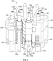
- Figure 3 is a partial sectional view of the connector assembly 100 in accordance with an exemplary embodiment.
- the connector assembly 100 includes different types of coaxial cable assemblies 126 within the same connector body 120.
- the connector assembly 100 includes a first coaxial cable assembly 126a having first coaxial cables 128a and first coaxial contacts 132a and a second coaxial cable assembly 126b having second coaxial cables 128b and second coaxial contacts 132b.
- the first coaxial cables 128a are smaller than the second coaxial cables 128b (for example, have smaller diameters).
- the first coaxial contacts 132a are smaller than the second coaxial contacts 132b (for example, have smaller diameters).
- the first coaxial contacts 132a utilize positioning adapters 200 to position the smaller first coaxial contacts 132a in the connector body 120.
- the positioning adapters 200 may make the first coaxial cable assemblies 126a have similar dimensions (for example, shape and size) as the second coaxial cable assemblies 126b.
- the connector body 120 is a multi-piece body.
- the connector body 120 includes a forward section 140 and a rear section 142.
- the forward and rear sections 140, 142 are discrete elements that are configured to be secured to each other, which may be secured to each other using hardware (e.g., screws).
- the forward section 140 includes a plurality of contact cavities 144
- the rear section 142 includes a plurality of contact cavities 146.
- the contact cavities 144, 146 are aligned with each other to form contact channels 148.
- Each of the contact channels 148 is configured to receive a portion of a corresponding coaxial cable assembly 126, such as a corresponding coaxial contact 132.
- the connector assembly 100 includes biasing springs 150 associated with the cable assemblies 126.
- the biasing springs 150 surround the cables 128.
- the biasing springs 150 forward bias the cable assemblies 126 in the contact channels 148.
- the biasing springs 150 are held in the contact channels 148 by the rear section 142.
- the biasing springs 150 may engage rear ledges or rear shoulders 152 of the rear section 142.
- the biasing springs 150 force the coaxial contacts 132 forward to engage front ledges or front shoulders 154 of the front section 140.
- the biasing springs 150 have a spring diameter 156, which may be similar to (for example, slightly smaller than) a contact channel diameter 158.
- the exterior of the biasing springs 150 may engage the interior surfaces of the contact channels 148 to position the biasing springs 150 in the contact channels 148.
- the biasing springs 150 may directly engage the second coaxial contacts 132b of the second coaxial cable assemblies 126b and may engage the positioning adapters 200 of the first coaxial cable assemblies 126a.
- Figure 4 is a cross-sectional view of a portion of the connector assembly 100 showing the second coaxial cable assembly 126b in accordance with an exemplary embodiment.
- the second coaxial contact 132b is terminated to the end of the second coaxial cable 128b.
- the coaxial cable 128b includes a center conductor 135b and a cable shield 137b.
- the center contact 134b is terminated to the center conductor 135b.
- the conductive shell 136b is terminated to the cable shield 137b.
- the insulator 138b is used to electrically isolate the center contact 134b from the conductive shell 136b.
- the conductive shell 136b is a multi-piece contact having a front contact 160b and a rear contact 162b.
- the front end of the rear contact 162b is press-fit into the front contact 160b.
- the biasing spring 150 engages a rear edge 164b of the rear contact 162b.
- a mating end 166b of the front contact 160b extends forward of the connector body 120.
- a shoulder 168b of the front contact 160b engages the front shoulder 154 of the forward section 140 of the connector body 120 to position the coaxial contact 132 relative to the connector body 120.
- the biasing spring 150 holds the coaxial contact 132b in the contact channel 148, such as forcing the shoulder 168b against the front shoulder 154.
- the coaxial contact 132b may be pressed rearward against the biasing spring 150 when mated with the connector assembly 300 (shown in Figure 1 ).
- the conductive shell 136b has a shell diameter 170.
- the shell diameter 170 may be similar to the spring diameter 156 such that the biasing spring 150 presses against the rear edge 164b.
- the shell diameter 170 is similar to the contact channel diameter 158.
- the conductive shell 136b may have a snug fit in the contact channel 148 to guide and position the center contact 134b in the contact channel 148 (for example, side-to-side).
- the conductive shell 136b is slidable within the contact channel 148.
- the mating end 166b of the front contact 160b has a mating end diameter 172 smaller than the shell diameter 170.
- the mating end diameter 172 may be similar to a front opening diameter 174 at the front shoulder 154 of the forward section 140.
- the shell diameter 170 is larger than the front opening diameter 174 to ensure that the coaxial contact 132b is captured in the contact channel 148 by the front shoulder 154.
- FIG. 5 is a cross-sectional view of a portion of the connector assembly 100 showing the first coaxial cable assembly 126a in accordance with an exemplary embodiment.
- the first coaxial cable assembly 126a uses the positioning adapter 200 to position the first coaxial contact 132a within the contact channel 148.
- the positioning adapter 200 is used to position the smaller sized first coaxial contact 132 and first coaxial cable 128a in the contact channel 148 designed to accept the larger diameter second coaxial cable assembly 126b.
- the first coaxial contact 132a is terminated to the end of the first coaxial cable 128a.
- the coaxial cable 128a includes a center conductor 135a and a cable shield 137b.
- the center conductor 135a may be a smaller diameter conductor compared to the center conductor 135b (shown in Figure 4 ).
- the center contact 134a is terminated to the center conductor 135a.
- the conductive shell 136a is terminated to the cable shield 137a.
- the insulator 138a is used to electrically isolate the center contact 134a from the conductive shell 136a.
- the conductive shell 136a is a multi-piece contact having a front contact 160a and a rear contact 162a.
- the front end of the rear contact 162a is press-fit into the front contact 160a.
- the front contact 160a and the rear contact 162a are loaded into the positioning adapter 200.
- a mating end 166a of the front contact 160a extends forward of the positioning adapter 200 and the connector body 120.
- the biasing spring 150 engages the positioning adapter 200 to forward bias the first coaxial cable assembly 126a in the contact channel 148.
- the positioning adapter 200 engages the front shoulder 154 of the forward section 140 of the connector body 120 to position the coaxial contact 132 relative to the connector body 120.
- the coaxial contact 132a may be pressed rearward against the biasing spring 150 when mated with the connector assembly 300 (shown in Figure 1 ).
- the conductive shell 136a has a shell diameter 176.
- the shell diameter 176 is less than the shell diameter 170 (shown in Figure 4 ).
- the shell diameter 176 is less than the front opening diameter 174 at the front shoulder 154 of the forward section 140.
- the conductive shell 136a may fit through the front opening of the forward section 140.
- the positioning adapter 200 is oversized relative to the front opening and wider than the front opening diameter 174. The positioning adapter 200 engages the front shoulder 154 to capture and position the coaxial contact 132a in the contact channel 148.
- the coaxial contact 132a includes a retention feature 180 to secure the positioning adapter 200 to the coaxial contact 132a.
- the retention feature 180 includes a circumferential groove 182.
- Other types of retention features may be used in alternative embodiments.
- the positioning adapter 200 engages the retention feature 180 to hold an axial position of the positioning adapter 200 relative to the coaxial contact 132a.
- the positioning adapter 200 engages the retention feature 180 to position the coaxial contact 132a relative to the positioning adapter 200.
- the positioning adapter 200 engages the connector body 120 to position the coaxial contact 132a in the contact cavity 146 relative to the connector body 120.
- FIG 6 is a front perspective view of the positioning adapter 200 in accordance with an exemplary embodiment.
- Figure 7 is a rear perspective view of the positioning adapter 200 in accordance with an exemplary embodiment.
- the positioning adapter 200 includes an adapter body 202 extending between a front 204 and a rear 206.
- the adapter body 202 includes an adapter bore 208 open at the front 204 and open at the rear 206.
- the adapter bore 208 is configured to receive the coaxial contact 132a (shown in Figure 5 ).
- the adapter body 202 is configured to surround the coaxial contact 132a.
- the adapter body 202 is manufactured from a plastic material.
- the adapter body 202 may be a molded part, such as an injection molded part.
- the adapter body 202 has a circular cross-section.
- the adapter body 202 may be generally cylindrical.
- the adapter body 202 includes a front lip 210 at the front 204 and a rear lip 212 at the rear 206.
- the front lip 210 and/or the rear lip 212 may be a flange.
- the adapter body 202 is stepped inward between the front lip 210 and the rear lip 212.
- the front lip 210 has a front lip diameter and the rear lip 212 has a rear lip diameter.
- the adapter body 202 has a first diameter between the front lip 210 and the rear lip 212 that is less than the front lip diameter and the rear lip diameter.
- the front lip 210 is used to position the positioning adapter 200 in the contact channel 148 (for example, position laterally, such as side-to-side).
- the rear lip 212 is used to position the positioning adapter 200 in the connector body 120 (for example, position axially, such as front-to-rear).
- the adapter body 202 includes a longitudinal slot 220 open at the rear 206 of the positioning adapter 200.
- the longitudinal slot 220 allows the adapter body 202 to flex outward when the coaxial contact 132a is loaded into the adapter bore 208.
- the adapter body 202 may be snapably coupled to the coaxial contact 132a when flexed at the longitudinal slot(s) 220.
- two longitudinal slots 220 are provided.
- the adapter body 202 may be a multi-piece body having a right half and a left half that are coupled together at a seam.
- the positioning adapter 200 includes a cleat 230 extending into the adapter bore 208 from an interior surface of the adapter body 202.
- the cleat 230 is configured to engage the retention feature 180 of the coaxial contact 132a to secure the positioning adapter 200 to the coaxial contact 132a.
- the cleat 230 is configured to be received in the circumferential groove 182.
- the cleat 230 holds an axial position of the adapter body 202 relative to the conductive shell 136a.
- the cleat 230 may be a rib or tab extending from the interior surface of the adapter body 202.
- the cleat 230 includes a front facing seating surface 232 and a rear facing ramp surface 234.
- the ramp surface 234 guides loading of the conductive shell 136a into the adapter bore 208.
- the seating surface 232 is received in the circumferential groove 182 and engages the front wall of the circumferential groove 182 to hold the axial position of the adapter body 202 relative to the conductive shell 136a.
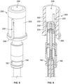
- Figure 8 is an exploded, front perspective view of the coaxial cable assembly 126a in accordance with an exemplary embodiment.
- Figure 9 is an exploded, partial sectional view of the coaxial cable assembly 126a in accordance with an exemplary embodiment.
- the coaxial contact 132a is loaded into the adapter bore 208.
- the front end of the coaxial contact 132a may be loaded into the rear 206 of the adapter body 202.
- the coaxial contact 132a is loaded into the adapter bore 208 to couple the cleat 230 to the retention feature 180.
- the cleat 230 may be received in the circumferential groove 182.
- the ramp surface 234 engages the coaxial contact 132a to spread the rear of the adapter body 202 apart, such as at the longitudinal slots 220.
- the adapter body 202 snaps inward to load the cleats 230 into the circumferential groove 182.
- the seating surface 232 is configured to engage the forward lip or shoulder of the circumferential groove 182 to retain the cleats 230 in the circumferential groove 182.
- the cleats 230 hold the axial position of the positioning adapter 200 relative to the coaxial contact 132a.
Landscapes
- Engineering & Computer Science (AREA)
- Microelectronics & Electronic Packaging (AREA)
- Coupling Device And Connection With Printed Circuit (AREA)
- Details Of Connecting Devices For Male And Female Coupling (AREA)
Abstract
Description
- The subject matter described and/or illustrated herein relates generally to coaxial connector assemblies.
- Coaxial connectors are known for interconnecting various coaxial components, such as coaxial cables, circuit boards, and/or the like. Coaxial connectors include one or more coaxial contact pairs. Each coaxial contact pair includes a center contact and a conductive shell that is arranged coaxially with the center contact. Coaxial connectors often include an array of coaxial contacts. The coaxial connectors may be designed to receive first types of coaxial contacts, such as coaxial contacts having a first diameter. Other coaxial connectors may be designed to receive second types of coaxial contacts, such as coaxial contacts having a second diameter. It may be desirable to utilize different types of coaxial contacts in the same coaxial connector. However, redesign of the coaxial connectors to arrange the different diameter coaxial contacts in the connector body is costly.
- There is a need for a coaxial connector assembly configured to receive different diameter coaxial contacts.
- The solution is provided by a coaxial connector assembly. The coaxial connector assembly includes a connector module having a connector body that includes contact channels extending therethrough between a front side and a rear side of the connector body. The front side faces in a mating direction for mating with a mating connector assembly. The coaxial connector assembly includes coaxial contacts received in the corresponding contact channels. The coaxial contacts are terminated to ends of coaxial cables. Each coaxial contact has a center contact, a conductive shell coaxial with the center contact, and an insulator between the center contact and the conductive shell. The conductive shell has a retention feature. The coaxial connector assembly includes positioning adapters received in the corresponding contact channels. Each positioning adapter includes an adapter body forming an adapter bore extending between a front and a rear of the positioning adapter. The adapter bore receives the corresponding coaxial contact such that the adapter body surrounds the coaxial contact. The adapter body engages the retention feature to position the coaxial contact relative to the adapter body. The adapter body engages the connector body to position the coaxial contact in the contact cavity relative to the connector body. The contact channel may comprise at least one contact cavity. The connector body may have a shoulder for the adapter body to engage. A spring in the contact cavity may bias the adapter body to engage the shoulder.
- The invention will now be described by way of example with reference to the accompanying drawings in which:
-
Figure 1 illustrates a communication system in accordance with an exemplary embodiment, showing a connector assembly and a mating connector assembly in an unmated state. -
Figure 2 is an exploded view of a portion of the communication system showing the connector assembly in accordance with an exemplary embodiment. -
Figure 3 is a partial sectional view of the connector assembly in accordance with an exemplary embodiment. -
Figure 4 is a cross-sectional view of a portion of the connector assembly showing the second coaxial cable assembly in accordance with an exemplary embodiment. -
Figure 5 is a cross-sectional view of a portion of the connector assembly showing the first coaxial cable assembly in accordance with an exemplary embodiment. -
Figure 6 is a front perspective view of the positioning adapter in accordance with an exemplary embodiment. -
Figure 7 is a rear perspective view of the positioning adapter in accordance with an exemplary embodiment. -
Figure 8 is an exploded, front perspective view of the coaxial cable assembly in accordance with an exemplary embodiment. -
Figure 9 is an exploded, partial sectional view of the coaxial cable assembly in accordance with an exemplary embodiment. - Embodiments set forth herein include coaxial connector assemblies and communication systems that include such coaxial connector assemblies. The communication system may include, for example, a circuit board that is secured to the coaxial connector assembly. In some embodiments, the communication system is a backplane (or midplane) communication system. As used herein, the terms backplane and midplane are used interchangeably and represent a system interface for multiple daughter card assemblies (e.g., line cards or switch cards). In other embodiments, the communication system is a circuit board assembly (e.g., daughter card assembly). One or more embodiments permit utilization of different sized coaxial contacts within the coaxial connector assembly. One or more embodiments permit two different sized coaxial contacts to be loaded into the same diameter contact channels in the coaxial connector assembly. One or more embodiments permit a connector module of the connector assembly to float during a mating operation. One or more embodiments enable using a denser grouping of coaxial contacts by permitting the coaxial contacts to be rear-loaded into the connector module. In particular embodiments, the connector module is permitted to float and also enables rear-loading of coaxial contacts.
- In an embodiment, a coaxial connector assembly is provided. The coaxial connector assembly includes a connector module having a connector body that includes contact channels extending therethrough between a front side and a rear side of the connector body. The front side faces in a mating direction for mating with a mating connector assembly. The coaxial connector assembly includes coaxial contacts received in the corresponding contact channels. The coaxial contacts are terminated to ends of coaxial cables. Each coaxial contact has a center contact, a conductive shell coaxial with the center contact, and an insulator between the center contact and the conductive shell. The conductive shell has a retention feature. The coaxial connector assembly includes positioning adapters received in the corresponding contact channels. Each positioning adapter includes an adapter body forming an adapter bore extending between a front and a rear of the positioning adapter. The adapter bore receives the corresponding coaxial contact such that the adapter body surrounds the coaxial contact. The adapter body engages the retention feature to position the coaxial contact relative to the adapter body. The adapter body engages the connector body to position the coaxial contact in the contact cavity relative to the connector body.
- In another embodiment, a coaxial connector assembly is provided. The coaxial connector assembly includes a connector module having a connector body that includes first contact channels and second contact channels extending therethrough between a front side and a rear side of the connector body. The front side faces in a mating direction for mating with a mating connector assembly. The coaxial connector assembly includes first coaxial contacts received in the corresponding first contact channels. The first coaxial contacts are terminated to ends of first coaxial cables. Each first coaxial contact has a first center contact, a first conductive shell coaxial with the first center contact, and a first insulator between the first center contact and the first conductive shell. The first conductive shell has a retention feature. The coaxial connector assembly includes second coaxial contacts received in the corresponding second contact channels. The second coaxial contacts are terminated to ends of second coaxial cables. Each second coaxial contact has a second center contact, a second conductive shell coaxial with the second center contact, and a second insulator between the second center contact and the second conductive shell. The coaxial connector assembly includes positioning adapters coupled to the corresponding first coaxial contacts. The positioning adapters are received in the corresponding first contact channels. Each positioning adapter includes an adapter body forming an adapter bore extending between a front and a rear of the positioning adapter. The adapter bore receives the corresponding first coaxial contact such that the adapter body surrounds the first coaxial contact. The adapter body engages the retention feature to position the coaxial contact relative to the adapter body. The adapter body engages the connector body to position the coaxial contact in the contact cavity relative to the connector body. The first contact channels have equivalent dimensions as the second contact channels. The adapter bodies have substantially similar diameters as the second conductive shells.
- In another embodiment, a coaxial contact assembly is provided. The coaxial contact assembly includes a center contact having a mating end and a cable end. The cable end is configured to be terminated to a conductor of a coaxial cable. The coaxial contact assembly includes a conductive shell coaxial with the center contact. The conductive shell has a mating end and a cable end. The cable end is configured to be terminated to a cable shield of the coaxial cable. The conductive shell includes a shell bore receiving the center contact. The conductive shell has a retention feature. The coaxial contact assembly includes an insulator received in the shell bore between the center contact and the conductive shell. The coaxial contact assembly includes a positioning adapter configured to be received in a contact cavity of a connector module. The positioning adapter includes an adapter body forming an adapter bore extending between a front and a rear of the positioning adapter. The adapter bore receives the conductive shell such that the adapter body surrounds an exterior of the conductive shell. The adapter body engages the retention feature to position the conductive shell relative to the adapter body and position the conductive shell in the contact cavity.
-
Figure 1 illustrates acommunication system 10 in accordance with an exemplary embodiment, showing aconnector assembly 100 and amating connector assembly 300 in an unmated state.Figure 2 is an exploded view of a portion of the communication system showing theconnector assembly 100 in accordance with an exemplary embodiment. In the illustrated embodiment, theconnector assemblies coaxial connector assemblies communication system 10 may be provided with other types of connector assemblies, such as pin and socket connector assemblies, fiber optic connector assemblies, and the like. Theconnector assemblies mating axis 191. For reference, theconnector assemblies mating axis 191, a firstlateral axis 192, and a secondlateral axis 193. - In some applications, the
connector assemblies communication system 10 may be configured for radiofrequency (RF) applications. In particular embodiments, thecommunication system 10 and/or its components, such as theconnector assembly 100 and/or 300, are configured to satisfy military and aerospace applications. For example, the components of thecommunication system 10 may be configured to satisfy one or more industry or government standards, such as MIL-STD-348. To illustrate one example of thecommunication system 10, theconnector assemblies connector assembly 300 may perform analog functions. Theconnector assembly 300 may be replaced with other connector assemblies that are configured to perform the same or different operations. The digital functions, including digital signal processing, may be performed by a communication component (not shown) that is coupled to theconnector assembly 100. The other communication component may be another daughter card assembly (not shown). - The
communication system 10 and/or its components (e.g., theconnector assembly 100 and/or 300) may be configured to satisfy one or more industry or government standards. By way of example only, embodiments may be configured to satisfy the VME International Trade Association (VITA) standards (e.g., VITA 48, VITA 67, et al.). Thecommunication system 10 and/or its components may have an operating speed that achieves 50 GHz or greater. In particular embodiments, thecommunication system 10 and/or its components may achieve an operating speed of 60 GHz or greater. It should be understood, however, that other embodiments may be configured for different standards and may be configured to operate at different speeds. In some configurations, embodiments may be configured to operate within the range of DC to 60.0 GHz. - In an exemplary embodiment, the
connector assembly 300 is a daughter card assembly having aconnector module 302. In various embodiments, theconnector module 302 may be mounted to asubstrate 306, which may be a circuit card, such as a daughter card. Theconnector assembly 300 includes aguide module 308 mounted to thesubstrate 306 proximate to theconnector module 302. Theguide module 308 is used to guide mating with theconnector assembly 100. In the illustrated embodiment, theguide module 308 includes an opening configured to receive an alignment pin. The opening may be chamfered or have a lead-in. Other types of guide features may be used in alternative embodiments, such as a guide post. In the illustrated embodiment, theconnector module 302 is a right-angle connector module having thesubstrate 306 oriented perpendicular to the mating face of theconnector module 302. Thesubstrate 306 is oriented perpendicular to the substrate of theconnector assembly 100. However, other orientations are possible in alternative embodiments. For example, theconnector module 302 may be a mezzanine connector having thesubstrate 306 oriented parallel to the mating face and parallel to the substrate of theconnector assembly 100. - The
connector module 302 includes aconnector body 310 holdingcable assemblies 320. Eachcable assembly 320 includes acable 322 and acontact 324 terminated to the end of thecable 322, and may be routed to a remote location. Alternatively, thecables 322 may be terminated to thesubstrate 306, such as via substrate contacts. In other alternative embodiments, thecontacts 324 may be terminated to thesubstrate 306 rather than havingcables 322. Theconnector body 310 includes a plurality of contact channels (not shown) receivingcorresponding cable assemblies 320. Theconnector body 310 includes alignment features 318 for aligning theconnector module 302 with theconnector assembly 100 during mating. In the illustrated embodiment, the alignment features 318 are openings. Other types of alignment features may be provided in alternative embodiments. The alignment features 318 may be arranged to provide keyed mating with theconnector assembly 100. - In various embodiments, the
contact 324 is a coaxial contact; however, other types of contacts may be provided in alternative embodiments, such as pin contacts, socket contacts, fiber optic contacts (for example, fiber optic ferrules), and the like. In an exemplary embodiment, thecoaxial contact 324 is an RF contact. Thecoaxial contact 324 includes an inner contact and an outer contact surrounding the inner contact. The inner contact is configured to be terminated to a conductor of the cable. The outer contact is configured to be terminated to a shield, such as a cable braid, of thecable 322. Other arrangements are possible in alternative embodiments. - The
connector assembly 100 includes aconnector module 102 holdingcoaxial cable assemblies 126 configured to be mated with thecable assemblies 320 of theconnector assembly 300. In an exemplary embodiment, theconnector assembly 100 includes a mountingframe 104 used to mount theconnector module 102 to a substrate, such as asupport wall 106. Thesupport wall 106 may be, for example, a circuit board, panel, or other type of wall. In various embodiments, theconnector module 102 is floatably held between the mountingframe 104 and thesupport wall 106 to allow movement and/or alignment of the coaxial cable assemblies. For example, theconnector module 102 is permitted to move in a lateral direction during a mating operation. - The mounting
frame 104 includes opposite mating and mountingsides side 112 is configured to be mounted to thesupport wall 106. The mountingframe 104 includes apassage 114 that extends through the mating and mountingsides passage 114 is sized and shaped to receive a portion of theconnector module 102. Theconnector module 102 includesalignment posts 118 extending forward therefrom to engage the mating connector assembly 300 (Figure 1 ) during the mating operation. The alignment posts 118 may be received in thealignment openings 318. In the illustrated embodiment, theconnector assembly 100 includes two alignment posts 118. In other embodiments, however, theconnector assembly 100 may include only onealignment post 118 or more than two alignment posts 118. - The
connector module 102 includes aconnector body 120 having afront side 122 and arear side 124. Thecoaxial cable assemblies 126 are coupled to theconnector body 120. Thecoaxial cable assemblies 126 may extend from thefront side 122. Thecoaxial cable assemblies 126 may extend from therear side 124. In an exemplary embodiment, thecoaxial cable assemblies 126 includecables 128 extending from therear side 124. Theconnector module 102 includes acontact array 130 ofcoaxial contacts 132 that are coupled to theconnector body 120. Thecoaxial contacts 132 may extend from thefront side 122 for mating with thecoaxial contacts 324. Theconnector body 120 holds thecoaxial contacts 132 at designated positions for engaging correspondingcoaxial contacts 324. In particular embodiments, a pitch (or center-to-center spacing) between adjacentcoaxial contacts 132 may be between 1.50 mm and 5.00 mm. In particular embodiments, the pitch may be between 2.00 mm and 3.50 mm or, more particularly, between 2.50 and 2.9. In other embodiments, however, the pitch may be greater or smaller. - The
coaxial contacts 132 represent terminating ends of the correspondingcoaxial cable assemblies 126. Each of thecoaxial contacts 132 includes acenter contact 134 and aconductive shell 136 that is coaxially aligned with thecenter contact 134. Thecenter contacts 134 andconductive shells 136 may be electrically coupled to signal and ground paths (not shown) through thecables 128 of thecoaxial cable assemblies 126. In alternative embodiments, thecoaxial contacts 132 are not elements of coaxial cables and may be configured for termination to other components, such as a circuit board. -
Figure 3 is a partial sectional view of theconnector assembly 100 in accordance with an exemplary embodiment. In an exemplary embodiment, theconnector assembly 100 includes different types ofcoaxial cable assemblies 126 within thesame connector body 120. For example, in the illustrated embodiment, theconnector assembly 100 includes a firstcoaxial cable assembly 126a having firstcoaxial cables 128a and firstcoaxial contacts 132a and a secondcoaxial cable assembly 126b having secondcoaxial cables 128b and secondcoaxial contacts 132b. The firstcoaxial cables 128a are smaller than the secondcoaxial cables 128b (for example, have smaller diameters). The firstcoaxial contacts 132a are smaller than the secondcoaxial contacts 132b (for example, have smaller diameters). In an exemplary embodiment, the firstcoaxial contacts 132a utilizepositioning adapters 200 to position the smaller firstcoaxial contacts 132a in theconnector body 120. Thepositioning adapters 200 may make the firstcoaxial cable assemblies 126a have similar dimensions (for example, shape and size) as the secondcoaxial cable assemblies 126b. - In various embodiments, the
connector body 120 is a multi-piece body. For example, theconnector body 120 includes aforward section 140 and arear section 142. The forward andrear sections forward section 140 includes a plurality ofcontact cavities 144, and therear section 142 includes a plurality ofcontact cavities 146. Thecontact cavities contact channels 148. Each of thecontact channels 148 is configured to receive a portion of a correspondingcoaxial cable assembly 126, such as a correspondingcoaxial contact 132. - In an exemplary embodiment, the
connector assembly 100 includes biasingsprings 150 associated with thecable assemblies 126. The biasing springs 150 surround thecables 128. The biasing springs 150 forward bias thecable assemblies 126 in thecontact channels 148. The biasing springs 150 are held in thecontact channels 148 by therear section 142. For example, the biasing springs 150 may engage rear ledges orrear shoulders 152 of therear section 142. The biasing springs 150 force thecoaxial contacts 132 forward to engage front ledges orfront shoulders 154 of thefront section 140. In an exemplary embodiment, the biasing springs 150 have aspring diameter 156, which may be similar to (for example, slightly smaller than) acontact channel diameter 158. The exterior of the biasing springs 150 may engage the interior surfaces of thecontact channels 148 to position the biasing springs 150 in thecontact channels 148. The biasing springs 150 may directly engage the secondcoaxial contacts 132b of the secondcoaxial cable assemblies 126b and may engage thepositioning adapters 200 of the firstcoaxial cable assemblies 126a. -
Figure 4 is a cross-sectional view of a portion of theconnector assembly 100 showing the secondcoaxial cable assembly 126b in accordance with an exemplary embodiment. The secondcoaxial contact 132b is terminated to the end of the secondcoaxial cable 128b. Thecoaxial cable 128b includes acenter conductor 135b and acable shield 137b. Thecenter contact 134b is terminated to thecenter conductor 135b. Theconductive shell 136b is terminated to thecable shield 137b. Theinsulator 138b is used to electrically isolate thecenter contact 134b from theconductive shell 136b. - In various embodiments, the
conductive shell 136b is a multi-piece contact having afront contact 160b and arear contact 162b. The front end of therear contact 162b is press-fit into thefront contact 160b. The biasingspring 150 engages arear edge 164b of therear contact 162b. Amating end 166b of thefront contact 160b extends forward of theconnector body 120. Ashoulder 168b of thefront contact 160b engages thefront shoulder 154 of theforward section 140 of theconnector body 120 to position thecoaxial contact 132 relative to theconnector body 120. The biasingspring 150 holds thecoaxial contact 132b in thecontact channel 148, such as forcing theshoulder 168b against thefront shoulder 154. Thecoaxial contact 132b may be pressed rearward against the biasingspring 150 when mated with the connector assembly 300 (shown inFigure 1 ). - In an exemplary embodiment, the
conductive shell 136b has ashell diameter 170. Theshell diameter 170 may be similar to thespring diameter 156 such that the biasingspring 150 presses against therear edge 164b. Theshell diameter 170 is similar to thecontact channel diameter 158. For example, theconductive shell 136b may have a snug fit in thecontact channel 148 to guide and position thecenter contact 134b in the contact channel 148 (for example, side-to-side). Theconductive shell 136b is slidable within thecontact channel 148. In an exemplary embodiment, themating end 166b of thefront contact 160b has amating end diameter 172 smaller than theshell diameter 170. Themating end diameter 172 may be similar to afront opening diameter 174 at thefront shoulder 154 of theforward section 140. Theshell diameter 170 is larger than thefront opening diameter 174 to ensure that thecoaxial contact 132b is captured in thecontact channel 148 by thefront shoulder 154. -
Figure 5 is a cross-sectional view of a portion of theconnector assembly 100 showing the firstcoaxial cable assembly 126a in accordance with an exemplary embodiment. The firstcoaxial cable assembly 126a uses thepositioning adapter 200 to position the firstcoaxial contact 132a within thecontact channel 148. Thepositioning adapter 200 is used to position the smaller sized firstcoaxial contact 132 and firstcoaxial cable 128a in thecontact channel 148 designed to accept the larger diameter secondcoaxial cable assembly 126b. The firstcoaxial contact 132a is terminated to the end of the firstcoaxial cable 128a. Thecoaxial cable 128a includes acenter conductor 135a and acable shield 137b. Thecenter conductor 135a may be a smaller diameter conductor compared to thecenter conductor 135b (shown inFigure 4 ). Thecenter contact 134a is terminated to thecenter conductor 135a. Theconductive shell 136a is terminated to thecable shield 137a. Theinsulator 138a is used to electrically isolate thecenter contact 134a from theconductive shell 136a. - In various embodiments, the
conductive shell 136a is a multi-piece contact having afront contact 160a and arear contact 162a. The front end of therear contact 162a is press-fit into thefront contact 160a. Thefront contact 160a and therear contact 162a are loaded into thepositioning adapter 200. Amating end 166a of thefront contact 160a extends forward of thepositioning adapter 200 and theconnector body 120. The biasingspring 150 engages thepositioning adapter 200 to forward bias the firstcoaxial cable assembly 126a in thecontact channel 148. Thepositioning adapter 200 engages thefront shoulder 154 of theforward section 140 of theconnector body 120 to position thecoaxial contact 132 relative to theconnector body 120. Thecoaxial contact 132a may be pressed rearward against the biasingspring 150 when mated with the connector assembly 300 (shown inFigure 1 ). - In an exemplary embodiment, the
conductive shell 136a has ashell diameter 176. Theshell diameter 176 is less than the shell diameter 170 (shown inFigure 4 ). In the illustrated embodiment, theshell diameter 176 is less than thefront opening diameter 174 at thefront shoulder 154 of theforward section 140. For example, theconductive shell 136a may fit through the front opening of theforward section 140. Thepositioning adapter 200 is oversized relative to the front opening and wider than thefront opening diameter 174. Thepositioning adapter 200 engages thefront shoulder 154 to capture and position thecoaxial contact 132a in thecontact channel 148. - The
coaxial contact 132a includes aretention feature 180 to secure thepositioning adapter 200 to thecoaxial contact 132a. In the illustrated embodiment, theretention feature 180 includes acircumferential groove 182. Other types of retention features may be used in alternative embodiments. Thepositioning adapter 200 engages theretention feature 180 to hold an axial position of thepositioning adapter 200 relative to thecoaxial contact 132a. Thepositioning adapter 200 engages theretention feature 180 to position thecoaxial contact 132a relative to thepositioning adapter 200. Thepositioning adapter 200 engages theconnector body 120 to position thecoaxial contact 132a in thecontact cavity 146 relative to theconnector body 120. -
Figure 6 is a front perspective view of thepositioning adapter 200 in accordance with an exemplary embodiment.Figure 7 is a rear perspective view of thepositioning adapter 200 in accordance with an exemplary embodiment. Thepositioning adapter 200 includes anadapter body 202 extending between a front 204 and a rear 206. Theadapter body 202 includes anadapter bore 208 open at the front 204 and open at the rear 206. The adapter bore 208 is configured to receive thecoaxial contact 132a (shown inFigure 5 ). Theadapter body 202 is configured to surround thecoaxial contact 132a. In an exemplary embodiment, theadapter body 202 is manufactured from a plastic material. For example, theadapter body 202 may be a molded part, such as an injection molded part. - In an exemplary embodiment, the
adapter body 202 has a circular cross-section. For example, theadapter body 202 may be generally cylindrical. Theadapter body 202 includes afront lip 210 at the front 204 and arear lip 212 at the rear 206. Thefront lip 210 and/or therear lip 212 may be a flange. Theadapter body 202 is stepped inward between thefront lip 210 and therear lip 212. Thefront lip 210 has a front lip diameter and therear lip 212 has a rear lip diameter. Theadapter body 202 has a first diameter between thefront lip 210 and therear lip 212 that is less than the front lip diameter and the rear lip diameter. Thefront lip 210 is used to position thepositioning adapter 200 in the contact channel 148 (for example, position laterally, such as side-to-side). Therear lip 212 is used to position thepositioning adapter 200 in the connector body 120 (for example, position axially, such as front-to-rear). - In an exemplary embodiment, the
adapter body 202 includes alongitudinal slot 220 open at the rear 206 of thepositioning adapter 200. Thelongitudinal slot 220 allows theadapter body 202 to flex outward when thecoaxial contact 132a is loaded into theadapter bore 208. Theadapter body 202 may be snapably coupled to thecoaxial contact 132a when flexed at the longitudinal slot(s) 220. In the illustrated embodiment, twolongitudinal slots 220 are provided. In alternative embodiments, theadapter body 202 may be a multi-piece body having a right half and a left half that are coupled together at a seam. - In an exemplary embodiment, the
positioning adapter 200 includes acleat 230 extending into the adapter bore 208 from an interior surface of theadapter body 202. Thecleat 230 is configured to engage theretention feature 180 of thecoaxial contact 132a to secure thepositioning adapter 200 to thecoaxial contact 132a. For example, thecleat 230 is configured to be received in thecircumferential groove 182. Thecleat 230 holds an axial position of theadapter body 202 relative to theconductive shell 136a. Thecleat 230 may be a rib or tab extending from the interior surface of theadapter body 202. In an exemplary embodiment, thecleat 230 includes a front facingseating surface 232 and a rear facingramp surface 234. Theramp surface 234 guides loading of theconductive shell 136a into theadapter bore 208. Theseating surface 232 is received in thecircumferential groove 182 and engages the front wall of thecircumferential groove 182 to hold the axial position of theadapter body 202 relative to theconductive shell 136a. -
Figure 8 is an exploded, front perspective view of thecoaxial cable assembly 126a in accordance with an exemplary embodiment.Figure 9 is an exploded, partial sectional view of thecoaxial cable assembly 126a in accordance with an exemplary embodiment. During assembly, thecoaxial contact 132a is loaded into theadapter bore 208. For example, the front end of thecoaxial contact 132a may be loaded into the rear 206 of theadapter body 202. - The
coaxial contact 132a is loaded into the adapter bore 208 to couple thecleat 230 to theretention feature 180. For example, thecleat 230 may be received in thecircumferential groove 182. During loading, theramp surface 234 engages thecoaxial contact 132a to spread the rear of theadapter body 202 apart, such as at thelongitudinal slots 220. When thecleats 230 clear thecircumferential groove 182, theadapter body 202 snaps inward to load thecleats 230 into thecircumferential groove 182. Theseating surface 232 is configured to engage the forward lip or shoulder of thecircumferential groove 182 to retain thecleats 230 in thecircumferential groove 182. Thecleats 230 hold the axial position of thepositioning adapter 200 relative to thecoaxial contact 132a.
Claims (11)
- A coaxial connector assembly (100) comprising:a connector module (102) having a connector body (120) that includes contact channels (148) extending therethrough between a front side (122) and a rear side (124) of the connector body, the front side (122) facing in a mating direction for mating with a mating connector assembly (300);coaxial contacts (132) received in the corresponding contact channels (148), the coaxial contacts being terminated to ends of coaxial cables (128), each coaxial contact having a center contact (134), a conductive shell (136) coaxial with the center contact, and an insulator (138a) between the center contact and the conductive shell, the conductive shell having a retention feature (180); andpositioning adapters (200) received in the corresponding contact channels (148), each positioning adapter including an adapter body (202) forming an adapter bore (208) extending between a front (204) and a rear (206) of the positioning adapter, the adapter bore (208) receiving the corresponding coaxial contact (132) such that the adapter body (202) surrounds the coaxial contact, the adapter body (202) engaging the retention feature (180) to position the coaxial contact (132) relative to the adapter body, the adapter body (202) engaging the connector body (120) to position the coaxial contact (132) in a contact cavity (144, 146) of the connector body relative to the connector body.
- The coaxial connector assembly (100) of claim 1, wherein the positioning adapter (200) engages the retention feature (180) to hold an axial position of the conductive shell (136) relative to the adapter body (202).
- The coaxial connector assembly (100) of claim 1 or 2, wherein the retention feature (180) includes a circumferential groove (182) in an exterior of the conductive shell (136), the positioning adapter (200) including a cleat (230) received in the circumferential groove to hold an axial position of the conductive shell relative to the adapter body (202).
- The coaxial connector assembly (100) of claim 3, wherein the cleat (230) includes a front facing seating surface (232) received in the circumferential groove (182) to hold the conductive shell (136) relative to the adapter body (202) and a rear facing ramp surface (234) to guide loading of the conductive shell into the adapter bore (208).
- The coaxial connector assembly (100) of any preceding claim, wherein the adapter body (202) is snapably coupled to the coaxial contact (132).
- The coaxial connector assembly (100) of any preceding claim, further comprising a spring (150) positioned in the contact cavity (144) rearward of the positioning adapter (200) and the coaxial contact (132), the spring pressing against the positioning adapter to forward bias the positioning adapter.
- The coaxial connector assembly (100) of claim 6, wherein the spring (150) has a spring diameter (156), the conductive shell (136) having a shell diameter (170) smaller than the spring diameter.
- The coaxial connector assembly (100) of any preceding claim, wherein the adapter body (202) includes a longitudinal slot (220) open at the rear of the positioning adapter (200) to allow the adapter body to flex outward when the conductive shell (136) is loaded into the adapter bore (208).
- The coaxial connector assembly (100) of any preceding claim, wherein the adapter body (202) includes a front lip (210) at the front (204) and a rear lip (212) at the rear (206), the adapter body having a first diameter between the front lip and the rear lip, the front lip having a front lip diameter (214) greater than the first diameter, the rear lip having a rear lip diameter (216) greater than the first diameter.
- The coaxial connector assembly (100) of any preceding claim, wherein the positioning or locating adapter (200) positions the coaxial contact (132) in a contact cavity (144) having a pass-through diameter greater than a diameter of the conductive shell (136).
- The coaxial connector assembly (100) of any preceding claim, wherein each contact channel (148) comprises at least one said contact cavity (144, 146).
Applications Claiming Priority (1)
| Application Number | Priority Date | Filing Date | Title |
|---|---|---|---|
| US17/012,246 US11394159B2 (en) | 2020-09-04 | 2020-09-04 | Positioning adapter for coaxial connector assembly |
Publications (2)
| Publication Number | Publication Date |
|---|---|
| EP3965234A1 true EP3965234A1 (en) | 2022-03-09 |
| EP3965234B1 EP3965234B1 (en) | 2025-10-08 |
Family
ID=77595417
Family Applications (1)
| Application Number | Title | Priority Date | Filing Date |
|---|---|---|---|
| EP21194320.4A Active EP3965234B1 (en) | 2020-09-04 | 2021-09-01 | Positioning adapter for coaxial connector assembly |
Country Status (4)
| Country | Link |
|---|---|
| US (1) | US11394159B2 (en) |
| EP (1) | EP3965234B1 (en) |
| CN (1) | CN114142310A (en) |
| CA (1) | CA3129909A1 (en) |
Families Citing this family (3)
| Publication number | Priority date | Publication date | Assignee | Title |
|---|---|---|---|---|
| FR3108203B1 (en) * | 2020-03-11 | 2023-06-02 | Axon Cable Sa | Quick and secure connection assembly |
| CN114744426A (en) * | 2022-03-14 | 2022-07-12 | 上海航天科工电器研究院有限公司 | A VITA67 RF Module Based on Gross Button Connection |
| EP4387011A1 (en) * | 2022-12-16 | 2024-06-19 | Mettler-Toledo GmbH | Connector element for a connector system |
Citations (7)
| Publication number | Priority date | Publication date | Assignee | Title |
|---|---|---|---|---|
| US3366920A (en) * | 1965-11-22 | 1968-01-30 | Amp Inc | Coaxial connector |
| US4708666A (en) * | 1986-09-15 | 1987-11-24 | Amp Incorporated | Triaxial to coaxial connector assembly |
| WO1997002629A1 (en) * | 1995-06-30 | 1997-01-23 | The Whitaker Corporation | Modular right-angle board mountable coaxial connector |
| US5934945A (en) * | 1997-03-05 | 1999-08-10 | Framatome Connectors Usa Inc. | Contact retainer for retaining a contact to a housing |
| US20160134032A1 (en) * | 2014-11-12 | 2016-05-12 | Tyco Electronics Corporation | Connector assembly |
| US9735519B2 (en) * | 2015-12-11 | 2017-08-15 | Te Connectivity Corporation | Coaxial connector assembly and communication system having a plurality of coaxial contacts |
| US20200169030A1 (en) * | 2016-03-03 | 2020-05-28 | Harting Electric Gmbh & Co. Kg | Module system for modular plug connectors |
Family Cites Families (21)
| Publication number | Priority date | Publication date | Assignee | Title |
|---|---|---|---|---|
| DE19746637C1 (en) * | 1997-10-22 | 1999-02-11 | Siemens Ag | High-frequency (HF) coaxial angle plug connector e.g coaxial monoblock type for SMD-circuit boards |
| TWI322539B (en) * | 2003-09-03 | 2010-03-21 | Randall A Holliday | Adapter for mini-coaxial cable |
| US7131868B2 (en) * | 2004-07-16 | 2006-11-07 | John Mezzalingua Associates, Inc. | Compression connector for coaxial cable |
| US7077697B2 (en) * | 2004-09-09 | 2006-07-18 | Corning Gilbert Inc. | Snap-in float-mount electrical connector |
| US7186138B2 (en) * | 2004-12-22 | 2007-03-06 | Insert Enterprise Co., Ltd. | Multiple pieces dual type BNC connector with all metal shell |
| US7014503B1 (en) * | 2004-12-22 | 2006-03-21 | Insert Enterprise Co., Ltd. | Multiple pieces dual type BNC connector |
| US7189114B1 (en) * | 2006-06-29 | 2007-03-13 | Corning Gilbert Inc. | Compression connector |
| US7588460B2 (en) * | 2007-04-17 | 2009-09-15 | Thomas & Betts International, Inc. | Coaxial cable connector with gripping ferrule |
| CH702048B1 (en) * | 2008-03-14 | 2011-04-29 | Huber+Suhner Ag | Multi-coaxial connector and method of mounting such a multiple coaxial cable connector. |
| US7607929B1 (en) * | 2008-06-30 | 2009-10-27 | Tyco Electronics Corporation | Electrical connector assembly having spring loaded electrical connector |
| US8123556B2 (en) * | 2009-04-09 | 2012-02-28 | Raytheon Company | Low profile compact RF coaxial to planar transmission line interface |
| US7704077B1 (en) * | 2009-04-13 | 2010-04-27 | Tyco Electronics Corporation | Low loss board to board connection system |
| US7896655B1 (en) * | 2009-08-14 | 2011-03-01 | Tyco Electronics Corporation | Multi-port connector system |
| US7922529B1 (en) * | 2009-11-23 | 2011-04-12 | Neocoil, Llc | High mating cycle low insertion force coaxial connector |
| US8002574B1 (en) * | 2010-11-04 | 2011-08-23 | Tyco Electronics Corporation | RF module with a housing with spring loaded connectors and a strain relief extending rearward of the housing |
| US8282415B1 (en) * | 2011-04-21 | 2012-10-09 | Tyco Electronics Corporation | Multi-port connector assembly |
| US20140206221A1 (en) * | 2013-01-21 | 2014-07-24 | Tyco Electronics Corporation | Daughtercard and backplane connectors |
| US10490941B2 (en) * | 2018-01-16 | 2019-11-26 | Te Connectivity Corporation | RF connector for an RF module |
| US10505322B2 (en) | 2018-01-19 | 2019-12-10 | Te Connectivity Corporation | Communication system having coaxial connector assembly |
| US10498061B1 (en) * | 2018-12-17 | 2019-12-03 | Te Connectivity Corporation | Coaxial connector assembly |
| US11075491B2 (en) * | 2019-01-15 | 2021-07-27 | Ezconn Corporation | Coaxial cable connector and universal coaxial cable fixing sleeve thereof |
-
2020
- 2020-09-04 US US17/012,246 patent/US11394159B2/en active Active
-
2021
- 2021-09-01 EP EP21194320.4A patent/EP3965234B1/en active Active
- 2021-09-02 CA CA3129909A patent/CA3129909A1/en active Pending
- 2021-09-02 CN CN202111025135.XA patent/CN114142310A/en active Pending
Patent Citations (7)
| Publication number | Priority date | Publication date | Assignee | Title |
|---|---|---|---|---|
| US3366920A (en) * | 1965-11-22 | 1968-01-30 | Amp Inc | Coaxial connector |
| US4708666A (en) * | 1986-09-15 | 1987-11-24 | Amp Incorporated | Triaxial to coaxial connector assembly |
| WO1997002629A1 (en) * | 1995-06-30 | 1997-01-23 | The Whitaker Corporation | Modular right-angle board mountable coaxial connector |
| US5934945A (en) * | 1997-03-05 | 1999-08-10 | Framatome Connectors Usa Inc. | Contact retainer for retaining a contact to a housing |
| US20160134032A1 (en) * | 2014-11-12 | 2016-05-12 | Tyco Electronics Corporation | Connector assembly |
| US9735519B2 (en) * | 2015-12-11 | 2017-08-15 | Te Connectivity Corporation | Coaxial connector assembly and communication system having a plurality of coaxial contacts |
| US20200169030A1 (en) * | 2016-03-03 | 2020-05-28 | Harting Electric Gmbh & Co. Kg | Module system for modular plug connectors |
Also Published As
| Publication number | Publication date |
|---|---|
| EP3965234B1 (en) | 2025-10-08 |
| CN114142310A (en) | 2022-03-04 |
| US20220077639A1 (en) | 2022-03-10 |
| CA3129909A1 (en) | 2022-03-04 |
| US11394159B2 (en) | 2022-07-19 |
Similar Documents
| Publication | Publication Date | Title |
|---|---|---|
| EP3671977B1 (en) | Coaxial connector assembly | |
| EP3514894B1 (en) | Communication system having coaxial connector module and fiber optic module | |
| US11121509B2 (en) | Electrical connector | |
| EP3965234B1 (en) | Positioning adapter for coaxial connector assembly | |
| CN112448226B (en) | Communication system having a connector assembly | |
| EP3514889B1 (en) | Coaxial connector assembly | |
| CA2756189C (en) | Rf connector assembly | |
| CA3007406C (en) | Coaxial connector assembly and communication system having a plurality of coaxial contacts | |
| US10505323B2 (en) | Communication system having coaxial connector assembly | |
| EP2946444B1 (en) | Electrical connector system with backplane connector and daughtercard connector | |
| US8360806B2 (en) | RF module | |
| US10297966B1 (en) | Mating adapter for an electrical connector assembly | |
| US20240396268A1 (en) | Electrical shielding for wafer assembly of electrical connector assembly | |
| US8758055B2 (en) | RF module | |
| US20250293461A1 (en) | Communication system having connector assembly |
Legal Events
| Date | Code | Title | Description |
|---|---|---|---|
| PUAI | Public reference made under article 153(3) epc to a published international application that has entered the european phase |
Free format text: ORIGINAL CODE: 0009012 |
|
| STAA | Information on the status of an ep patent application or granted ep patent |
Free format text: STATUS: THE APPLICATION HAS BEEN PUBLISHED |
|
| AK | Designated contracting states |
Kind code of ref document: A1 Designated state(s): AL AT BE BG CH CY CZ DE DK EE ES FI FR GB GR HR HU IE IS IT LI LT LU LV MC MK MT NL NO PL PT RO RS SE SI SK SM TR |
|
| STAA | Information on the status of an ep patent application or granted ep patent |
Free format text: STATUS: REQUEST FOR EXAMINATION WAS MADE |
|
| 17P | Request for examination filed |
Effective date: 20220901 |
|
| RBV | Designated contracting states (corrected) |
Designated state(s): AL AT BE BG CH CY CZ DE DK EE ES FI FR GB GR HR HU IE IS IT LI LT LU LV MC MK MT NL NO PL PT RO RS SE SI SK SM TR |
|
| RAP1 | Party data changed (applicant data changed or rights of an application transferred) |
Owner name: TE CONNECTIVITY SOLUTIONS GMBH |
|
| STAA | Information on the status of an ep patent application or granted ep patent |
Free format text: STATUS: EXAMINATION IS IN PROGRESS |
|
| 17Q | First examination report despatched |
Effective date: 20240102 |
|
| REG | Reference to a national code |
Ref country code: DE Free format text: PREVIOUS MAIN CLASS: H01R0013426000 Ipc: H05K0007140000 Ref country code: DE Ref legal event code: R079 Ref document number: 602021039955 Country of ref document: DE Free format text: PREVIOUS MAIN CLASS: H01R0013426000 Ipc: H05K0007140000 |
|
| GRAP | Despatch of communication of intention to grant a patent |
Free format text: ORIGINAL CODE: EPIDOSNIGR1 |
|
| STAA | Information on the status of an ep patent application or granted ep patent |
Free format text: STATUS: GRANT OF PATENT IS INTENDED |
|
| RIC1 | Information provided on ipc code assigned before grant |
Ipc: H01R 13/24 20060101ALI20250604BHEP Ipc: H01R 24/52 20110101ALI20250604BHEP Ipc: H01R 13/426 20060101ALI20250604BHEP Ipc: H05K 7/14 20060101AFI20250604BHEP |
|
| INTG | Intention to grant announced |
Effective date: 20250617 |
|
| GRAS | Grant fee paid |
Free format text: ORIGINAL CODE: EPIDOSNIGR3 |
|
| GRAA | (expected) grant |
Free format text: ORIGINAL CODE: 0009210 |
|
| STAA | Information on the status of an ep patent application or granted ep patent |
Free format text: STATUS: THE PATENT HAS BEEN GRANTED |
|
| AK | Designated contracting states |
Kind code of ref document: B1 Designated state(s): AL AT BE BG CH CY CZ DE DK EE ES FI FR GB GR HR HU IE IS IT LI LT LU LV MC MK MT NL NO PL PT RO RS SE SI SK SM TR |
|
| REG | Reference to a national code |
Ref country code: GB Ref legal event code: FG4D Ref country code: CH Ref legal event code: F10 Free format text: ST27 STATUS EVENT CODE: U-0-0-F10-F00 (AS PROVIDED BY THE NATIONAL OFFICE) Effective date: 20251008 |
|
| REG | Reference to a national code |
Ref country code: DE Ref legal event code: R096 Ref document number: 602021039955 Country of ref document: DE |
|
| REG | Reference to a national code |
Ref country code: IE Ref legal event code: FG4D |
|
| REG | Reference to a national code |
Ref country code: NL Ref legal event code: MP Effective date: 20251008 |
|
| REG | Reference to a national code |
Ref country code: AT Ref legal event code: MK05 Ref document number: 1846023 Country of ref document: AT Kind code of ref document: T Effective date: 20251008 |
|
| PG25 | Lapsed in a contracting state [announced via postgrant information from national office to epo] |
Ref country code: NL Free format text: LAPSE BECAUSE OF FAILURE TO SUBMIT A TRANSLATION OF THE DESCRIPTION OR TO PAY THE FEE WITHIN THE PRESCRIBED TIME-LIMIT Effective date: 20251008 |
|
| PG25 | Lapsed in a contracting state [announced via postgrant information from national office to epo] |
Ref country code: ES Free format text: LAPSE BECAUSE OF FAILURE TO SUBMIT A TRANSLATION OF THE DESCRIPTION OR TO PAY THE FEE WITHIN THE PRESCRIBED TIME-LIMIT Effective date: 20251008 |
|
| REG | Reference to a national code |
Ref country code: LT Ref legal event code: MG9D |
|
| PG25 | Lapsed in a contracting state [announced via postgrant information from national office to epo] |
Ref country code: NO Free format text: LAPSE BECAUSE OF FAILURE TO SUBMIT A TRANSLATION OF THE DESCRIPTION OR TO PAY THE FEE WITHIN THE PRESCRIBED TIME-LIMIT Effective date: 20260108 |
|
| PG25 | Lapsed in a contracting state [announced via postgrant information from national office to epo] |
Ref country code: AT Free format text: LAPSE BECAUSE OF FAILURE TO SUBMIT A TRANSLATION OF THE DESCRIPTION OR TO PAY THE FEE WITHIN THE PRESCRIBED TIME-LIMIT Effective date: 20251008 Ref country code: FI Free format text: LAPSE BECAUSE OF FAILURE TO SUBMIT A TRANSLATION OF THE DESCRIPTION OR TO PAY THE FEE WITHIN THE PRESCRIBED TIME-LIMIT Effective date: 20251008 Ref country code: HR Free format text: LAPSE BECAUSE OF FAILURE TO SUBMIT A TRANSLATION OF THE DESCRIPTION OR TO PAY THE FEE WITHIN THE PRESCRIBED TIME-LIMIT Effective date: 20251008 |
|
| PG25 | Lapsed in a contracting state [announced via postgrant information from national office to epo] |
Ref country code: RS Free format text: LAPSE BECAUSE OF FAILURE TO SUBMIT A TRANSLATION OF THE DESCRIPTION OR TO PAY THE FEE WITHIN THE PRESCRIBED TIME-LIMIT Effective date: 20260108 |
|
| PG25 | Lapsed in a contracting state [announced via postgrant information from national office to epo] |
Ref country code: IS Free format text: LAPSE BECAUSE OF FAILURE TO SUBMIT A TRANSLATION OF THE DESCRIPTION OR TO PAY THE FEE WITHIN THE PRESCRIBED TIME-LIMIT Effective date: 20260208 |
|
| PG25 | Lapsed in a contracting state [announced via postgrant information from national office to epo] |
Ref country code: PT Free format text: LAPSE BECAUSE OF FAILURE TO SUBMIT A TRANSLATION OF THE DESCRIPTION OR TO PAY THE FEE WITHIN THE PRESCRIBED TIME-LIMIT Effective date: 20260209 |
|
| PG25 | Lapsed in a contracting state [announced via postgrant information from national office to epo] |
Ref country code: PL Free format text: LAPSE BECAUSE OF FAILURE TO SUBMIT A TRANSLATION OF THE DESCRIPTION OR TO PAY THE FEE WITHIN THE PRESCRIBED TIME-LIMIT Effective date: 20251008 |
|
| PG25 | Lapsed in a contracting state [announced via postgrant information from national office to epo] |
Ref country code: LV Free format text: LAPSE BECAUSE OF FAILURE TO SUBMIT A TRANSLATION OF THE DESCRIPTION OR TO PAY THE FEE WITHIN THE PRESCRIBED TIME-LIMIT Effective date: 20251008 |
|
| PG25 | Lapsed in a contracting state [announced via postgrant information from national office to epo] |
Ref country code: BG Free format text: LAPSE BECAUSE OF FAILURE TO SUBMIT A TRANSLATION OF THE DESCRIPTION OR TO PAY THE FEE WITHIN THE PRESCRIBED TIME-LIMIT Effective date: 20251008 |
|
| PG25 | Lapsed in a contracting state [announced via postgrant information from national office to epo] |
Ref country code: LT Free format text: LAPSE BECAUSE OF FAILURE TO SUBMIT A TRANSLATION OF THE DESCRIPTION OR TO PAY THE FEE WITHIN THE PRESCRIBED TIME-LIMIT Effective date: 20251008 |
|
| PG25 | Lapsed in a contracting state [announced via postgrant information from national office to epo] |
Ref country code: SM Free format text: LAPSE BECAUSE OF FAILURE TO SUBMIT A TRANSLATION OF THE DESCRIPTION OR TO PAY THE FEE WITHIN THE PRESCRIBED TIME-LIMIT Effective date: 20251008 |
|
| PG25 | Lapsed in a contracting state [announced via postgrant information from national office to epo] |
Ref country code: DK Free format text: LAPSE BECAUSE OF FAILURE TO SUBMIT A TRANSLATION OF THE DESCRIPTION OR TO PAY THE FEE WITHIN THE PRESCRIBED TIME-LIMIT Effective date: 20251008 |
|
| PG25 | Lapsed in a contracting state [announced via postgrant information from national office to epo] |
Ref country code: IT Free format text: LAPSE BECAUSE OF FAILURE TO SUBMIT A TRANSLATION OF THE DESCRIPTION OR TO PAY THE FEE WITHIN THE PRESCRIBED TIME-LIMIT Effective date: 20251008 |
|
| PG25 | Lapsed in a contracting state [announced via postgrant information from national office to epo] |
Ref country code: EE Free format text: LAPSE BECAUSE OF FAILURE TO SUBMIT A TRANSLATION OF THE DESCRIPTION OR TO PAY THE FEE WITHIN THE PRESCRIBED TIME-LIMIT Effective date: 20251008 |
|
| PG25 | Lapsed in a contracting state [announced via postgrant information from national office to epo] |
Ref country code: CZ Free format text: LAPSE BECAUSE OF FAILURE TO SUBMIT A TRANSLATION OF THE DESCRIPTION OR TO PAY THE FEE WITHIN THE PRESCRIBED TIME-LIMIT Effective date: 20251008 |
|
| PG25 | Lapsed in a contracting state [announced via postgrant information from national office to epo] |
Ref country code: SK Free format text: LAPSE BECAUSE OF FAILURE TO SUBMIT A TRANSLATION OF THE DESCRIPTION OR TO PAY THE FEE WITHIN THE PRESCRIBED TIME-LIMIT Effective date: 20251008 |
|
| PG25 | Lapsed in a contracting state [announced via postgrant information from national office to epo] |
Ref country code: SE Free format text: LAPSE BECAUSE OF FAILURE TO SUBMIT A TRANSLATION OF THE DESCRIPTION OR TO PAY THE FEE WITHIN THE PRESCRIBED TIME-LIMIT Effective date: 20251008 |
|
| PLBE | No opposition filed within time limit |
Free format text: ORIGINAL CODE: 0009261 |
|
| STAA | Information on the status of an ep patent application or granted ep patent |
Free format text: STATUS: NO OPPOSITION FILED WITHIN TIME LIMIT |