EP3965226A1 - Radiator assembly - Google Patents
Radiator assembly Download PDFInfo
- Publication number
- EP3965226A1 EP3965226A1 EP21195370.8A EP21195370A EP3965226A1 EP 3965226 A1 EP3965226 A1 EP 3965226A1 EP 21195370 A EP21195370 A EP 21195370A EP 3965226 A1 EP3965226 A1 EP 3965226A1
- Authority
- EP
- European Patent Office
- Prior art keywords
- feeder
- hook
- leg
- radiator assembly
- base station
- Prior art date
- Legal status (The legal status is an assumption and is not a legal conclusion. Google has not performed a legal analysis and makes no representation as to the accuracy of the status listed.)
- Granted
Links
Images


Classifications
-
- H—ELECTRICITY
- H01—ELECTRIC ELEMENTS
- H01Q—ANTENNAS, i.e. RADIO AERIALS
- H01Q21/00—Antenna arrays or systems
- H01Q21/24—Combinations of antenna units polarised in different directions for transmitting or receiving circularly and elliptically polarised waves or waves linearly polarised in any direction
- H01Q21/26—Turnstile or like antennas comprising arrangements of three or more elongated elements disposed radially and symmetrically in a horizontal plane about a common centre
-
- H—ELECTRICITY
- H01—ELECTRIC ELEMENTS
- H01Q—ANTENNAS, i.e. RADIO AERIALS
- H01Q1/00—Details of, or arrangements associated with, antennas
- H01Q1/36—Structural form of radiating elements, e.g. cone, spiral, umbrella; Particular materials used therewith
-
- H—ELECTRICITY
- H01—ELECTRIC ELEMENTS
- H01Q—ANTENNAS, i.e. RADIO AERIALS
- H01Q1/00—Details of, or arrangements associated with, antennas
- H01Q1/12—Supports; Mounting means
- H01Q1/22—Supports; Mounting means by structural association with other equipment or articles
- H01Q1/24—Supports; Mounting means by structural association with other equipment or articles with receiving set
- H01Q1/241—Supports; Mounting means by structural association with other equipment or articles with receiving set used in mobile communications, e.g. GSM
- H01Q1/246—Supports; Mounting means by structural association with other equipment or articles with receiving set used in mobile communications, e.g. GSM specially adapted for base stations
-
- H—ELECTRICITY
- H01—ELECTRIC ELEMENTS
- H01Q—ANTENNAS, i.e. RADIO AERIALS
- H01Q1/00—Details of, or arrangements associated with, antennas
- H01Q1/36—Structural form of radiating elements, e.g. cone, spiral, umbrella; Particular materials used therewith
- H01Q1/38—Structural form of radiating elements, e.g. cone, spiral, umbrella; Particular materials used therewith formed by a conductive layer on an insulating support
-
- H—ELECTRICITY
- H01—ELECTRIC ELEMENTS
- H01Q—ANTENNAS, i.e. RADIO AERIALS
- H01Q21/00—Antenna arrays or systems
- H01Q21/0006—Particular feeding systems
-
- H—ELECTRICITY
- H01—ELECTRIC ELEMENTS
- H01Q—ANTENNAS, i.e. RADIO AERIALS
- H01Q21/00—Antenna arrays or systems
- H01Q21/06—Arrays of individually energised antenna units similarly polarised and spaced apart
- H01Q21/061—Two dimensional planar arrays
- H01Q21/062—Two dimensional planar arrays using dipole aerials
-
- H—ELECTRICITY
- H01—ELECTRIC ELEMENTS
- H01Q—ANTENNAS, i.e. RADIO AERIALS
- H01Q9/00—Electrically-short antennas having dimensions not more than twice the operating wavelength and consisting of conductive active radiating elements
- H01Q9/04—Resonant antennas
- H01Q9/16—Resonant antennas with feed intermediate between the extremities of the antenna, e.g. centre-fed dipole
- H01Q9/26—Resonant antennas with feed intermediate between the extremities of the antenna, e.g. centre-fed dipole with folded element or elements, the folded parts being spaced apart a small fraction of operating wavelength
Definitions
- the disclosure relates to the communication field, and in particular relates to a radiator assembly for a base station antenna.
- a large number of base stations are involved in a mobile communication network, various base stations may comprise base station antennas, and the base station antennas are used to receive and/or transmit radio frequency signals.
- a base station antenna may comprise a plurality of radiator assemblies, which may also be referred to as radiating elements or antenna elements. The miniaturization of the sizes of radiator assemblies is desirable.
- An object of the disclosure is to provide a compact radiator assembly for a base station antenna.
- a radiator assembly for a base station antenna has one longitudinal central axis and two dipoles cross-arranged around the longitudinal central axis, and each dipole has two dipole arms, wherein each dipole arm is equipped with a hook-like feeder made of a metal sheet and having a free end portion, and the hook-like feeder is capacitively coupled with an associated dipole arm.
- each dipole arm may be made of a metal sheet, and the dipole arm may comprise a feeder stem extending longitudinally and a radiating portion extending transversely by reference to the longitudinal central axis.
- the radiator assembly may comprise a feeder stem consisting of a printed circuit board (PCB), and the dipole arms may be formed on another common PCB.
- PCB printed circuit board
- each hook-like feeder may be mounted radially inside or outside the feeder stem by reference to the longitudinal central axis.
- a pair of hook-like feeders placed opposite to each other may be mounted radially inside or outside the feeder stem by reference to the longitudinal central axis.
- the hook-like feeders may be mounted radially inside the feeder stems by reference to the longitudinal central axis.
- the hook-like feeders may be mounted radially outside the feeder stems by reference to the longitudinal central axis.
- a first pair of hook-like feeders placed opposite to each other may be mounted radially inside the feeder stems and a second pair of hook-like feeders placed opposite to each other may be mounted radially outside the feeder stems by reference to the longitudinal central axis.
- each hook-like feeder may comprise a first leg, a second leg and a connecting segment connecting the first leg and the second leg, the first leg may be configured to be electrically connected to a feeder panel through an end portion of the first leg, and the second leg may have the free end portion.
- first leg and the second leg may extend longitudinally by reference to the longitudinal central axis, the first leg may be located in the area of the feeder stem of the dipole arm adjacent to the associated dipole arm, the second leg may be located in the area of the feeder stem of the associated dipole arm in the circumferential direction of the radiator assembly, and the connecting segment may cross the feeder stem of the adjacent dipole arm and the feeder stem of the associated dipole arm.
- each feeder stem may be planar.
- each feeder stem may be bent.
- each hook-like feeder may be planar.
- each hook-like feeder may be bent.
- the first leg may be parallel to the feeder stem of the adjacent dipole arm
- the second leg may be parallel to the feeder stem of the associated dipole arm
- the connecting segment may be bent
- the first leg and the second leg may form a right angle.
- each feeder stem may be configured to be bent and may comprise a plurality of planar sections extending longitudinally, and each hook-like feeder may be configured to be planar, wherein the first leg may be parallel to one planar section of the feeder stem of the adjacent dipole arm, and the second leg may be parallel to one planar section of the feeder stem of the associated dipole arm.
- each feeder stem may be C-shaped and each feeder stem may comprise three side-by-side planar sections extending longitudinally in the cross-section perpendicular to the longitudinal central axis.
- the radiator assembly may comprise a common radiator support, the radiator support is configured to be mounted on a panel assembly having a reflecting panel and a feeder panel, and the dipole arms may be mounted on the common radiator support.
- the hook-like feeders mounted radially outside the feeder stems may be mounted on the common radiator support.
- the radiator assembly may comprise a central support, and the central support may be mounted at the center of the common radiator support.
- the hook-like feeders mounted radially inside the feeder stems may be mounted on the central support.
- the central support may have a top component.
- the top component may go beyond the radiating portions of the dipole arms by reference to the longitudinal central axis.
- the central support may have a top component, a columnar body and a bottom component, and the top component and the bottom component may be connected to the body.
- the top component may have at least a claw element, for example, a plurality of claw elements, configured to hold hook-like feeders.
- the bottom component may have at least a claw element, for example, a plurality of claw elements, configured to hold hook-like feeders.
- the top component may have at least a snap hook configured to detachably and longitudinally fix hook-like feeders.
- the bottom component may have at least a snap hook configured to detachably and longitudinally fix hook-like feeders.
- a radiator assembly for a base station antenna comprising first through fourth dipole arms arranged to define a cross shape, where each dipole arm includes a longitudinally-extending feeder stem and a transversely-extending radiating portion, first through fourth hook-like feeders, wherein at least some of the feeder stems or at least some of the hook-like feeders include at least two longitudinally-extending bends.
- each hook-like feeder may include the at least two longitudinally-extending bends, and at least first and second of the hook-like feeders may be positioned outside a rectangle defined by the feeder stems when viewed in plan view.
- third and fourth of the hook-like feeders may be positioned inside the rectangle defined by the feeder stems when viewed in plan view.
- each feeder stem may include the at least two longitudinally-extending bends, and each hook-like feeder may be positioned radially outside a respective one of the feeder stems.
- each longitudinally-extending bend may define a 45 degree angle.
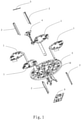
- Fig. 1 is an exploded view of the radiator assembly in a first embodiment
- Fig. 2 is a perspective view of the radiator assembly in the assembled state in a second embodiment of the present invention.
- the first and second embodiments mainly differ in the outline of a support table 18 of the radiator support.
- the first and second embodiments may be the same in other aspects.
- the radiator assembly may have a longitudinal central axis (not shown in the drawings) and two dipoles cross-arranged around the longitudinal central axis. Each dipole may have two dipole arms 1. Each dipole arm 1 may be made of metal, and may be separate from the other dipole arms. Alternatively, the dipole arms 1 may be formed on a common PCB. Each dipole arm 1 may comprise a single piece or may comprise multiple pieces.
- Each dipole arm 1 may be equipped with a hook-like feeder 2 made of a metal sheet.
- the hook-like feeder 2 may be electrically connected to the feeder panel (e.g., a printed circuit board feeder panel) of a panel assembly 6 only locally described in Figs. 1 and 2 , and has a free end portion and is capacitively coupled with an associated dipole arm 1.
- the panel assembly may further comprise a reflecting panel.
- the hook-like feeder may be, for example, galvanically connected to the conductive traces of the feeder panel, and may be capacitively coupled with an associated dipole arm so that radio frequency signals can be transmitted between the feeder panel and the dipole arm via the hook-like feeder.
- the radiator assembly may comprise a common radiator support 3.
- the radiator support may be mounted to extend forwardly from the panel assembly, and the dipole arms 1 may be mounted on the common radiator support 3.
- the radiator assembly may comprise a central support 4 that is mounted at the center of the radiator support 3.
- the radiator support 3 may have a central recess 20 for accommodating the central support 4.
- the central support 4 may have a top component 21 (see FIG. 6A ).
- a parasitic element 5 may be mounted on the top component 21, and the parasitic element 5 is configured to adapt to the electrical properties of the radiator assembly.
- Fig. 3 is a perspective view of an embodiment of the dipole arm 1.
- the dipole arm may be made of a metal, for example, formed by stamping a metal sheet.
- the dipole arm 1 may comprise a radiating portion 11 and a feeder stem 12.
- the feeder stem 12 may extend longitudinally, for example, parallel to the longitudinal central axis, and the radiating portion 11 may extend on a transverse plane transverse to the longitudinal central axis.
- the radiating portion 11 may have at least a lappet 11a bent from the transverse plane to increase the bandwidth of the radiator assembly. Two exemplary lappets 11a can be seen in Fig. 3 .
- Fig. 4 is a perspective view of an embodiment of a pair of hook-like feeders 2.
- the pair of hook-like feeders 2 may respectively match a dipole arm 1.
- Each hook-like feeder 2 may be made of a metal, for example, formed by stamping a metal sheet.
- Each hook-like feeder 2 may comprise a first leg 13, a second leg 14, and a connecting segment 15 connecting the first leg 13 and the second leg 14.
- the first leg 13 may be electrically connected to the feeder panel of the panel assembly 6 through an end portion 16 of the first leg 13.
- the second leg 14 may have a free end portion 17.
- Each hook-like feeder 2 may be configured to be capacitively coupled to the associated dipole arm 1 to transmit radio frequency signals.
- Each hook-like feeder 2 may be mounted radially inside or outside the feeder stem 12.
- Figs. 8A and 8B are schematic views of two different structures and layouts of the hook-like feeders 2 and the feeder stems 12 which are viewed from the top along the longitudinal central axis of the radiator assembly, and the two figures describe the sections of the feeder stems 12 and the projections of the hook-like feeders 2 along the longitudinal central axis of the radiator assembly.
- each feeder stem 12 may be planar, and each hook-like feeder 2 may be bent.
- a first pair of hook-like feeders 2 positioned opposite to each other may be mounted radially inside the feeder stems 12, and a second pair of hook-like feeders 2 positioned opposite to each other may be mounted radially outside the feeder stems 12.
- the first leg 13 and the second leg 14 may extend longitudinally.
- the first leg 13 may be located in the area of the feeder stem of the dipole arm adjacent to the associated dipole arm
- the second leg 14 may be located in the area of the feeder stem of the associated dipole arm
- the connecting segment 15 may cross the feeder stem of the adjacent dipole arm and the feeder stem of the associated dipole arm.
- each feeder stem 12 may be bent, and each hook-like feeder may be planar.
- each feeder stem 12 may be C-shaped and each feeder stem 12 may comprise three planar sections extending longitudinally, and each hook-like feeder 2 may be configured to be planar, wherein the first leg 13 may be parallel to one planar section 29 of the feeder stem 12 of the adjacent dipole arm 1, and the second leg 14 may be parallel to one planar section 30 of the feeder stem 12 of the associated dipole arm 1, and the connecting segment 15 may cross the feeder stem of the adjacent dipole arm and the feeder stem of the associated dipole arm.
- the hook-like feeders 2 may be mounted radially outside the feeder stems 12. In addition, it is possible that the hook-like feeders 2 may be mounted radially inside the feeder stems 12.
- Figs. 5A and 5B are perspective views of the radiator support 3 at different angles of view.
- the radiator support 3 may have a support table 18 and a strut 19.
- the radiator support 3 may have a central recess 20 for accommodating the central support 4 which will be described in detail later.
- the radiating portions 11 of the dipole arms 1 may be supported and fixed on the support table 18 of the radiator support 3.
- the strut 19 may be fixed on the panel assembly 6 with a plurality of fasteners (not shown in the drawings).
- the hook-like feeders 2 mounted radially outside the feeder stems 12 may be directly mounted on the radiator support 3.
- Figs. 6A and 6B are perspective views of the central support 4 at different angles of view.
- the central support 4 may have a top component 21, a columnar body 22 and a bottom component 23, and the top component and the bottom component are connected to the body.
- the top component 21 may have a plurality of claws 24 on the top surface and the claws may be configured to fix the parasitic element 5.
- the top component 21 may have one or more claws 25 on its lower side.
- the bottom component 23 may have one or more claws 26.
- the claws 25 and the claws 26 may be configured to fix the hook-like feeders 2 mounted radially inside the feeder stems 12.
- the central support 4 may have at least three corresponding claws 25, 26, for example, two claws 25 and two claws 26.
- the central support 4 may have snap hooks configured to detachably and longitudinally fix the central support 4.
- the top component and the bottom component may have a plurality of snap hooks 27, 28, respectively.
- Fig. 7 is an outline view of the dipole arms of the radiator assembly in a third embodiment of the present invention. Only the plan view of the dipole arms 1 is described in Fig. 7 .
- Each radiating portion 11 may be configured to be roughly triangular and the four radiating portions 11 may form an outline of a rough square in whole.
- the inductors that are shown on the dipole arms may be implemented as narrow meandered metal sections (e.g., U-shaped metal sections) that connect wide metal segments of the dipole arms.
Landscapes
- Engineering & Computer Science (AREA)
- Computer Networks & Wireless Communication (AREA)
- Support Of Aerials (AREA)
- Variable-Direction Aerials And Aerial Arrays (AREA)
Abstract
Description
- The present application claims priority to
Chinese Patent Application No. 202010931976.6, filed September 8, 2020 - The disclosure relates to the communication field, and in particular relates to a radiator assembly for a base station antenna.
- A large number of base stations are involved in a mobile communication network, various base stations may comprise base station antennas, and the base station antennas are used to receive and/or transmit radio frequency signals. A base station antenna may comprise a plurality of radiator assemblies, which may also be referred to as radiating elements or antenna elements. The miniaturization of the sizes of radiator assemblies is desirable.
- An object of the disclosure is to provide a compact radiator assembly for a base station antenna.
- The object is achieved by a radiator assembly for a base station antenna, the radiator assembly has one longitudinal central axis and two dipoles cross-arranged around the longitudinal central axis, and each dipole has two dipole arms, wherein each dipole arm is equipped with a hook-like feeder made of a metal sheet and having a free end portion, and the hook-like feeder is capacitively coupled with an associated dipole arm.
- In some embodiments, each dipole arm may be made of a metal sheet, and the dipole arm may comprise a feeder stem extending longitudinally and a radiating portion extending transversely by reference to the longitudinal central axis.
- In some embodiments, the radiator assembly may comprise a feeder stem consisting of a printed circuit board (PCB), and the dipole arms may be formed on another common PCB.
- In some embodiments, each hook-like feeder may be mounted radially inside or outside the feeder stem by reference to the longitudinal central axis.
- In some embodiments, a pair of hook-like feeders placed opposite to each other may be mounted radially inside or outside the feeder stem by reference to the longitudinal central axis.
- In some embodiments, the hook-like feeders may be mounted radially inside the feeder stems by reference to the longitudinal central axis.
- In some embodiments, the hook-like feeders may be mounted radially outside the feeder stems by reference to the longitudinal central axis.
- In some embodiments, a first pair of hook-like feeders placed opposite to each other may be mounted radially inside the feeder stems and a second pair of hook-like feeders placed opposite to each other may be mounted radially outside the feeder stems by reference to the longitudinal central axis.
- In some embodiments, each hook-like feeder may comprise a first leg, a second leg and a connecting segment connecting the first leg and the second leg, the first leg may be configured to be electrically connected to a feeder panel through an end portion of the first leg, and the second leg may have the free end portion.
- In some embodiments, the first leg and the second leg may extend longitudinally by reference to the longitudinal central axis, the first leg may be located in the area of the feeder stem of the dipole arm adjacent to the associated dipole arm, the second leg may be located in the area of the feeder stem of the associated dipole arm in the circumferential direction of the radiator assembly, and the connecting segment may cross the feeder stem of the adjacent dipole arm and the feeder stem of the associated dipole arm.
- In some embodiments, each feeder stem may be planar.
- In some embodiments, each feeder stem may be bent.
- In some embodiments, each hook-like feeder may be planar.
- In some embodiments, each hook-like feeder may be bent.
- In some embodiments, the first leg may be parallel to the feeder stem of the adjacent dipole arm, the second leg may be parallel to the feeder stem of the associated dipole arm, and the connecting segment may be bent.
- In some embodiments, the first leg and the second leg may form a right angle.
- In some embodiments, each feeder stem may be configured to be bent and may comprise a plurality of planar sections extending longitudinally, and each hook-like feeder may be configured to be planar, wherein the first leg may be parallel to one planar section of the feeder stem of the adjacent dipole arm, and the second leg may be parallel to one planar section of the feeder stem of the associated dipole arm.
- In some embodiments, each feeder stem may be C-shaped and each feeder stem may comprise three side-by-side planar sections extending longitudinally in the cross-section perpendicular to the longitudinal central axis.
- In some embodiments, the radiator assembly may comprise a common radiator support, the radiator support is configured to be mounted on a panel assembly having a reflecting panel and a feeder panel, and the dipole arms may be mounted on the common radiator support.
- In some embodiments, the hook-like feeders mounted radially outside the feeder stems may be mounted on the common radiator support.
- In some embodiments, the radiator assembly may comprise a central support, and the central support may be mounted at the center of the common radiator support.
- In some embodiments, the hook-like feeders mounted radially inside the feeder stems may be mounted on the central support.
- In some embodiments, the central support may have a top component.
- In some embodiments, the top component may go beyond the radiating portions of the dipole arms by reference to the longitudinal central axis.
- In some embodiments, the central support may have a top component, a columnar body and a bottom component, and the top component and the bottom component may be connected to the body.
- In some embodiments, the top component may have at least a claw element, for example, a plurality of claw elements, configured to hold hook-like feeders.
- In some embodiments, the bottom component may have at least a claw element, for example, a plurality of claw elements, configured to hold hook-like feeders.
- In some embodiments, the top component may have at least a snap hook configured to detachably and longitudinally fix hook-like feeders.
- In some embodiments, the bottom component may have at least a snap hook configured to detachably and longitudinally fix hook-like feeders.
- According to another aspect of the disclosure, a radiator assembly for a base station antenna is proposed, the radiator assembly comprising first through fourth dipole arms arranged to define a cross shape, where each dipole arm includes a longitudinally-extending feeder stem and a transversely-extending radiating portion, first through fourth hook-like feeders, wherein at least some of the feeder stems or at least some of the hook-like feeders include at least two longitudinally-extending bends.
- In some embodiments, each hook-like feeder may include the at least two longitudinally-extending bends, and at least first and second of the hook-like feeders may be positioned outside a rectangle defined by the feeder stems when viewed in plan view.
- In some embodiments, third and fourth of the hook-like feeders may be positioned inside the rectangle defined by the feeder stems when viewed in plan view.
- In some embodiments, each feeder stem may include the at least two longitudinally-extending bends, and each hook-like feeder may be positioned radially outside a respective one of the feeder stems.
- In some embodiments, each longitudinally-extending bend may define a 45 degree angle.
- The technical characteristics mentioned above, the technical characteristics to be mentioned below, and the technical characteristics which may be obtained from the drawings may be combined arbitrarily as long as these technical characteristics do not conflict with each other. All technically feasible characteristic combinations are technical contents stated in the disclosure.
-
-
Fig. 1 is an exploded view of the radiator assembly in a first embodiment of the present invention. -
Fig. 2 is a perspective view of the radiator assembly in an assembled state in a second embodiment of the present invention. -
Fig. 3 is a perspective view of an embodiment of a dipole arm. -
Fig. 4 is a perspective view of a pair of hook-like feeders. -
Figs. 5A and5B are perspective views of the radiator support at different angles of view. -
Figs. 6A and6B are perspective views of the central support at different angles of view. -
Fig. 7 is an outline view of the dipole arms of the radiator assembly in a third embodiment of the present invention. -
Figs. 8A and 8B are schematic views of two different structures and layouts of hook-like feeders and feeder stems. - The general structure of the radiator assembly for a base station antenna in some embodiments of the present invention is described below with reference to
Figs. 1 and2 , whereinFig. 1 is an exploded view of the radiator assembly in a first embodiment, andFig. 2 is a perspective view of the radiator assembly in the assembled state in a second embodiment of the present invention. The first and second embodiments mainly differ in the outline of a support table 18 of the radiator support. The first and second embodiments may be the same in other aspects. - The radiator assembly may have a longitudinal central axis (not shown in the drawings) and two dipoles cross-arranged around the longitudinal central axis. Each dipole may have two
dipole arms 1. Eachdipole arm 1 may be made of metal, and may be separate from the other dipole arms. Alternatively, thedipole arms 1 may be formed on a common PCB. Eachdipole arm 1 may comprise a single piece or may comprise multiple pieces. - Each
dipole arm 1 may be equipped with a hook-like feeder 2 made of a metal sheet. Through one end, the hook-like feeder 2 may be electrically connected to the feeder panel (e.g., a printed circuit board feeder panel) of apanel assembly 6 only locally described inFigs. 1 and2 , and has a free end portion and is capacitively coupled with an associateddipole arm 1. The panel assembly may further comprise a reflecting panel. The hook-like feeder may be, for example, galvanically connected to the conductive traces of the feeder panel, and may be capacitively coupled with an associated dipole arm so that radio frequency signals can be transmitted between the feeder panel and the dipole arm via the hook-like feeder. - The radiator assembly may comprise a
common radiator support 3. The radiator support may be mounted to extend forwardly from the panel assembly, and thedipole arms 1 may be mounted on thecommon radiator support 3. - The radiator assembly may comprise a
central support 4 that is mounted at the center of theradiator support 3. Theradiator support 3 may have acentral recess 20 for accommodating thecentral support 4. Thecentral support 4 may have a top component 21 (seeFIG. 6A ). Aparasitic element 5 may be mounted on thetop component 21, and theparasitic element 5 is configured to adapt to the electrical properties of the radiator assembly. -
Fig. 3 is a perspective view of an embodiment of thedipole arm 1. The dipole arm may be made of a metal, for example, formed by stamping a metal sheet. Thedipole arm 1 may comprise a radiatingportion 11 and afeeder stem 12. By reference to the longitudinal central axis of the radiator assembly, thefeeder stem 12 may extend longitudinally, for example, parallel to the longitudinal central axis, and the radiatingportion 11 may extend on a transverse plane transverse to the longitudinal central axis. The radiatingportion 11 may have at least alappet 11a bent from the transverse plane to increase the bandwidth of the radiator assembly. Twoexemplary lappets 11a can be seen inFig. 3 . -
Fig. 4 is a perspective view of an embodiment of a pair of hook-like feeders 2. The pair of hook-like feeders 2 may respectively match adipole arm 1. Each hook-like feeder 2 may be made of a metal, for example, formed by stamping a metal sheet. Each hook-like feeder 2 may comprise afirst leg 13, asecond leg 14, and a connectingsegment 15 connecting thefirst leg 13 and thesecond leg 14. Thefirst leg 13 may be electrically connected to the feeder panel of thepanel assembly 6 through anend portion 16 of thefirst leg 13. Thesecond leg 14 may have afree end portion 17. Each hook-like feeder 2 may be configured to be capacitively coupled to the associateddipole arm 1 to transmit radio frequency signals. Each hook-like feeder 2 may be mounted radially inside or outside thefeeder stem 12. -
Figs. 8A and 8B are schematic views of two different structures and layouts of the hook-like feeders 2 and the feeder stems 12 which are viewed from the top along the longitudinal central axis of the radiator assembly, and the two figures describe the sections of the feeder stems 12 and the projections of the hook-like feeders 2 along the longitudinal central axis of the radiator assembly. - As shown in
Fig. 8A , each feeder stem 12 may be planar, and each hook-like feeder 2 may be bent. A first pair of hook-like feeders 2 positioned opposite to each other may be mounted radially inside the feeder stems 12, and a second pair of hook-like feeders 2 positioned opposite to each other may be mounted radially outside the feeder stems 12. By reference to the longitudinal central axis of the radiator assembly, thefirst leg 13 and thesecond leg 14 may extend longitudinally. In the circumferential direction of the radiator assembly, thefirst leg 13 may be located in the area of the feeder stem of the dipole arm adjacent to the associated dipole arm, thesecond leg 14 may be located in the area of the feeder stem of the associated dipole arm, and the connectingsegment 15 may cross the feeder stem of the adjacent dipole arm and the feeder stem of the associated dipole arm. - As shown in
Fig. 8B , each feeder stem 12 may be bent, and each hook-like feeder may be planar. In a cross-section perpendicular to the longitudinal central axis, each feeder stem 12 may be C-shaped and each feeder stem 12 may comprise three planar sections extending longitudinally, and each hook-like feeder 2 may be configured to be planar, wherein thefirst leg 13 may be parallel to oneplanar section 29 of the feeder stem 12 of theadjacent dipole arm 1, and thesecond leg 14 may be parallel to oneplanar section 30 of the feeder stem 12 of the associateddipole arm 1, and the connectingsegment 15 may cross the feeder stem of the adjacent dipole arm and the feeder stem of the associated dipole arm. The hook-like feeders 2 may be mounted radially outside the feeder stems 12. In addition, it is possible that the hook-like feeders 2 may be mounted radially inside the feeder stems 12. -
Figs. 5A and5B are perspective views of theradiator support 3 at different angles of view. Theradiator support 3 may have a support table 18 and astrut 19. Theradiator support 3 may have acentral recess 20 for accommodating thecentral support 4 which will be described in detail later. The radiatingportions 11 of thedipole arms 1 may be supported and fixed on the support table 18 of theradiator support 3. Thestrut 19 may be fixed on thepanel assembly 6 with a plurality of fasteners (not shown in the drawings). The hook-like feeders 2 mounted radially outside the feeder stems 12 may be directly mounted on theradiator support 3. -
Figs. 6A and6B are perspective views of thecentral support 4 at different angles of view. Thecentral support 4 may have atop component 21, acolumnar body 22 and abottom component 23, and the top component and the bottom component are connected to the body. Thetop component 21 may have a plurality ofclaws 24 on the top surface and the claws may be configured to fix theparasitic element 5. Thetop component 21 may have one ormore claws 25 on its lower side. Thebottom component 23 may have one ormore claws 26. Theclaws 25 and theclaws 26 may be configured to fix the hook-like feeders 2 mounted radially inside the feeder stems 12. For each hook-like feeder 2 mounted radially inside the feeder stem, thecentral support 4 may have at least threecorresponding claws claws 25 and twoclaws 26. Thecentral support 4 may have snap hooks configured to detachably and longitudinally fix thecentral support 4. For example, the top component and the bottom component may have a plurality of snap hooks 27, 28, respectively. -
Fig. 7 is an outline view of the dipole arms of the radiator assembly in a third embodiment of the present invention. Only the plan view of thedipole arms 1 is described inFig. 7 . Each radiatingportion 11 may be configured to be roughly triangular and the four radiatingportions 11 may form an outline of a rough square in whole. The inductors that are shown on the dipole arms may be implemented as narrow meandered metal sections (e.g., U-shaped metal sections) that connect wide metal segments of the dipole arms. - It will be understood that, the terminology used herein is for the purpose of describing particular aspects only and is not intended to be limiting of the disclosure. As used herein, the singular forms "a", "an" and "the" are intended to include the plural forms as well, unless the context clearly indicates otherwise. It will be further understood that the terms "comprise" and "include" (and variants thereof), when used in this specification, specify the presence of stated operations, elements, and/or components, but do not preclude the presence or addition of one or more other operations, elements, components, and/or groups thereof. As used herein, the term "and/or" includes any and all combinations of one or more of the associated listed items. Like reference numbers signify like elements throughout the description of the figures.
- The thicknesses of elements in the drawings may be exaggerated for the sake of clarity. Further, it will be understood that when an element is referred to as being "on," "coupled to" or "connected to" another element, the element may be formed directly on, coupled to or connected to the other element, or there may be one or more intervening elements therebetween. In contrast, terms such as "directly on," "directly coupled to" and "directly connected to," when used herein, indicate that no intervening elements are present. Other words used to describe the relationship between elements should be interpreted in a like fashion (i.e., "between" versus "directly between", "attached" versus "directly attached," "adjacent" versus "directly adjacent", etc.).
- Terms such as "top," "bottom," "upper," "lower," "above," "below," and the like are used herein to describe the relationship of one element, layer or region to another element, layer or region as illustrated in the figures. It will be understood that these terms are intended to encompass different orientations of the device in addition to the orientation depicted in the figures.
- It will be understood that, although the terms "first," "second," etc. may be used herein to describe various elements, these elements should not be limited by these terms. These terms are only used to distinguish one element from another. Thus, a first element could be termed a second element without departing from the teachings of the inventive concept.
- It will also be appreciated that all example embodiments disclosed herein can be combined in any way.
- Finally, it is to be noted that, the above-described embodiments are merely for understanding the present invention but not constitute a limit on the protection scope of the present invention. For those skilled in the art, modifications may be made on the basis of the above-described embodiments, and these modifications do not depart from the protection scope of the present invention.
- The preferred aspects of the present disclosure may be summarized as follows:
- 1. A radiator assembly having a longitudinal central axis for a base station antenna, comprising:
- two dipoles cross-arranged around the longitudinal central axis, each dipole having two dipole arms,
- wherein each dipole arm is equipped with a hook-like sheet metal feeder and has a free end portion, and the hook-like feeder is capacitively coupled with an associated dipole arm.
- 2. The radiator assembly for a base station antenna according to
aspect 1, wherein each dipole arm is made of a metal sheet, and the dipole arm comprises a feeder stem extending longitudinally and a radiating portion extending transversely by reference to the longitudinal central axis. - 3. The radiator assembly for a base station antenna according to any one of the preceding aspects, in
particular aspect 2, wherein each hook-like feeder is mounted radially inside or outside the feeder stem by reference to the longitudinal central axis. - 4. The radiator assembly for a base station antenna according to any one of the preceding aspects, in
particular aspect 3, wherein a pair of hook-like feeders are positioned opposite to each other and are mounted radially inside or outside respective feeder stems by reference to the longitudinal central axis. - 5. The radiator assembly for a base station antenna according to any one of the preceding aspects, in
particular aspect 3, wherein the hook-like feeders are mounted radially inside the feeder stems by reference to the longitudinal central axis. - 6. The radiator assembly for a base station antenna according to any one of the preceding aspects, in
particular aspect 3, wherein hook-like feeders are mounted radially outside the feeder stems by reference to the longitudinal central axis. - 7. The radiator assembly for a base station antenna according to any one of the preceding aspects, in
particular aspect 3, wherein a first pair of hook-like feeders are positioned opposite to each other and are mounted radially inside the feeder stems and a second pair of hook-like feeders are positioned opposite to each other and are mounted radially outside the feeder stems by reference to the longitudinal central axis. - 8. The radiator assembly for a base station antenna according to any one of the preceding aspects, in
particular aspects 1 to 7, wherein each hook-like feeder comprises a first leg, a second leg, and a connecting segment connecting the first leg and the second leg, the first leg is configured to be electrically connected to a feeder panel through an end portion of the first leg, and the second leg has the free end portion. - 9. The radiator assembly for a base station antenna according to any one of the preceding aspects, in particular aspect 8, wherein the first leg and the second leg extend longitudinally by reference to the longitudinal central axis, the first leg is located in an area of the feeder stem of the dipole arm adjacent to the associated dipole arm and the second leg is located in an area of the feeder stem of the associated dipole arm in the circumferential direction of the radiator assembly, and the connecting segment crosses the feeder stem of the adjacent dipole arm and the feeder stem of the associated dipole arm.
- 10. The radiator assembly for a base station antenna according to any one of the preceding aspects, in particular aspect 9, wherein each feeder stem is planar, the first leg is parallel to the feeder stem of the adjacent dipole arm, the second leg is parallel to the feeder stem of the associated dipole arm, and the connecting segment is bent.
- 11. The radiator assembly for a base station antenna according to any one of the preceding aspects, in particular aspect 10, wherein the first leg and the second leg form a right angle.
- 12. The radiator assembly for a base station antenna according to any one of the preceding aspects, in particular aspect 9, wherein each feeder stem is bent and comprises a plurality of planar sections extending longitudinally, and each hook-like feeder is planar, wherein the first leg is parallel to one planar section of the feeder stem of the adjacent dipole arm, and the second leg is parallel to one planar section of the feeder stem of the associated dipole arm.
- 13. The radiator assembly for a base station antenna according to any one of the preceding aspects, in
particular aspect 12, wherein each feeder stem is C-shaped and each feeder stem comprises three side-by-side planar sections extending longitudinally in a cross-section perpendicular to the longitudinal central axis. - 14. The radiator assembly for a base station antenna according to any one of the preceding aspects, in
particular aspects 1 to 7, wherein the radiator assembly comprises a common radiator support, the radiator support is configured to be mounted on a panel assembly having a reflecting panel and a feeder panel, and the dipole arms are mounted on the common radiator support. - 15. The radiator assembly for a base station antenna according to any one of the preceding aspects, in
particular aspect 14, wherein the hook-like feeders that are mounted radially outside the feeder stems are mounted on the common radiator support. - 16. The radiator assembly for a base station antenna according to any one of the preceding aspects, in
particular aspect 14, wherein the radiator assembly comprises a central support, the central support is mounted at the center of the common radiator support, and the hook-like feeders that are mounted radially inside the feeder stems are mounted on the central support. - 17. The radiator assembly for a base station antenna according to any one of the preceding aspects, in
particular aspect 16, wherein the central support has a top component, a columnar body and a bottom component, the top component and the bottom component are connected to the body, and the top component and the bottom component respectively have at least a claw element configured to hold hook-like feeders. - 18. The radiator assembly for a base station antenna according to any one of the preceding aspects, in
particular aspect 17, wherein the top component and the bottom component respectively have at least a snap hook configured to detachably and longitudinally fix hook-like feeders. - 19. The radiator assembly for a base station antenna according to any one of the preceding aspects, in
particular aspect 17, wherein the top component goes beyond the radiating portions of the dipole arms by reference to the longitudinal central axis, and a parasitic element is mounted on the top component. - 20. A radiator assembly for a base station antenna, comprising:
- first through fourth dipole arms arranged to define a cross shape, where each dipole arm includes a longitudinally-extending feeder stem and a transversely-extending radiating portion;
- first through fourth hook-like feeders,
- wherein at least some of the feeder stems or at least some of the hook-like feeders include at least two longitudinally-extending bends.
- 21. The radiator assembly for a base station antenna of any one of the preceding aspects, in
particular aspect 20, wherein each hook-like feeder includes the at least two longitudinally-extending bends, and at least first and second of the hook-like feeders are positioned outside a rectangle defined by the feeder stems when viewed in plan view. - 22. The radiator assembly for a base station antenna of any one of the preceding aspects, in
particular aspect 21, wherein third and fourth of the hook-like feeders are positioned inside the rectangle defined by the feeder stems when viewed in plan view. - 23. The radiator assembly for a base station antenna of any one of the preceding aspects, in
particular aspect 20, wherein each feeder stem includes the at least two longitudinally-extending bends, and each hook-like feeder is positioned radially outside a respective one of the feeder stems. - 24. The radiator assembly for a base station antenna of any one of the preceding aspects, in
particular aspect 20, wherein each longitudinally-extending bend defines a 45 degree angle.
Claims (15)
- A radiator assembly having a longitudinal central axis for a base station antenna, comprising:two dipoles cross-arranged around the longitudinal central axis, each dipole having two dipole arms,wherein each dipole arm is equipped with a hook-like sheet metal feeder and has a free end portion, and the hook-like feeder is capacitively coupled with an associated dipole arm.
- The radiator assembly for a base station antenna according to claim 1, wherein each dipole arm is made of a metal sheet, and the dipole arm comprises a feeder stem extending longitudinally and a radiating portion extending transversely by reference to the longitudinal central axis.
- The radiator assembly for a base station antenna according to claim 2, wherein each hook-like feeder is mounted radially inside or outside the feeder stem by reference to the longitudinal central axis.
- The radiator assembly for a base station antenna according to either claim 2 or claim 3, wherein a pair of hook-like feeders are positioned opposite to each other and are mounted radially inside or outside respective feeder stems by reference to the longitudinal central axis.
- The radiator assembly for a base station antenna according to any of claims 2 to 4, wherein the hook-like feeders are mounted radially inside the feeder stems by reference to the longitudinal central axis.
- The radiator assembly for a base station antenna according to any of claims 2 to 5, wherein hook-like feeders are mounted radially outside the feeder stems by reference to the longitudinal central axis.
- The radiator assembly for a base station antenna according to any of claims 2 to 6, wherein a first pair of hook-like feeders are positioned opposite to each other and are mounted radially inside the feeder stems and a second pair of hook-like feeders are positioned opposite to each other and are mounted radially outside the feeder stems by reference to the longitudinal central axis.
- The radiator assembly for a base station antenna according to any one of claims 1 to 7, wherein each hook-like feeder comprises a first leg, a second leg, and a connecting segment connecting the first leg and the second leg, the first leg is configured to be electrically connected to a feeder panel through an end portion of the first leg, and the second leg has the free end portion.
- The radiator assembly for a base station antenna according to any of the previous claims, in particular claim 8, wherein the first leg and the second leg extend longitudinally by reference to the longitudinal central axis, the first leg is located in an area of the feeder stem of the dipole arm adjacent to the associated dipole arm and the second leg is located in an area of the feeder stem of the associated dipole arm in the circumferential direction of the radiator assembly, and the connecting segment crosses the feeder stem of the adjacent dipole arm and the feeder stem of the associated dipole arm.
- The radiator assembly for a base station antenna according to either claim 8 or claim 9, wherein each feeder stem is planar, the first leg is parallel to the feeder stem of the adjacent dipole arm, the second leg is parallel to the feeder stem of the associated dipole arm, and the connecting segment is bent.
- The radiator assembly for a base station antenna according to any of claims 8 to 10, wherein each feeder stem is bent and comprises a plurality of planar sections extending longitudinally, and each hook-like feeder is planar, wherein the first leg is parallel to one planar section of the feeder stem of the adjacent dipole arm, and the second leg is parallel to one planar section of the feeder stem of the associated dipole arm.
- The radiator assembly for a base station antenna according to any of claims 8 to 11, wherein each feeder stem is C-shaped and each feeder stem comprises three side-by-side planar sections extending longitudinally in a cross-section perpendicular to the longitudinal central axis.
- The radiator assembly for a base station antenna according to any one of claims 1 to 7, wherein the radiator assembly comprises a common radiator support, the radiator support is configured to be mounted on a panel assembly having a reflecting panel and a feeder panel, and the dipole arms are mounted on the common radiator support.
- The radiator assembly for a base station antenna according to claim 13, wherein the hook-like feeders that are mounted radially outside the feeder stems are mounted on the common radiator support.
- The radiator assembly for a base station antenna according to either claim 13 or claim 14, wherein the radiator assembly comprises a central support, the central support is mounted at the center of the common radiator support, and the hook-like feeders that are mounted radially inside the feeder stems are mounted on the central support.
Applications Claiming Priority (1)
| Application Number | Priority Date | Filing Date | Title |
|---|---|---|---|
| CN202010931976.6A CN114156635B (en) | 2020-09-08 | 2020-09-08 | Radiator assembly |
Publications (2)
| Publication Number | Publication Date |
|---|---|
| EP3965226A1 true EP3965226A1 (en) | 2022-03-09 |
| EP3965226B1 EP3965226B1 (en) | 2025-03-05 |
Family
ID=77666275
Family Applications (1)
| Application Number | Title | Priority Date | Filing Date |
|---|---|---|---|
| EP21195370.8A Active EP3965226B1 (en) | 2020-09-08 | 2021-09-07 | Radiator assembly |
Country Status (3)
| Country | Link |
|---|---|
| US (2) | US11742596B2 (en) |
| EP (1) | EP3965226B1 (en) |
| CN (1) | CN114156635B (en) |
Families Citing this family (1)
| Publication number | Priority date | Publication date | Assignee | Title |
|---|---|---|---|---|
| CN119487700A (en) * | 2022-07-01 | 2025-02-18 | 户外无线网络有限公司 | Crossed dipole radiating element with frequency selective surface and base station antenna with such radiating element |
Citations (2)
| Publication number | Priority date | Publication date | Assignee | Title |
|---|---|---|---|---|
| US20180294550A1 (en) * | 2015-11-03 | 2018-10-11 | Huawei Technologies Co., Ltd. | Antenna element preferably for a base station antenna |
| US20200185838A1 (en) * | 2018-12-10 | 2020-06-11 | Commscope Technologies Llc | Radiator assembly for base station antenna and base station antenna |
Family Cites Families (5)
| Publication number | Priority date | Publication date | Assignee | Title |
|---|---|---|---|---|
| CN201199545Y (en) * | 2008-05-28 | 2009-02-25 | 摩比天线技术(深圳)有限公司 | Wide band dual-polarization antennae array |
| WO2019009951A1 (en) * | 2017-07-05 | 2019-01-10 | Commscope Technologies Llc | Base station antennas having radiating elements with sheet metal-on dielectric dipole radiators and related radiating elements |
| CN111193099B (en) * | 2020-02-20 | 2021-01-12 | 深圳国人科技股份有限公司 | Dual-polarized radiation unit and base station antenna |
| CN113748572B (en) * | 2020-03-24 | 2022-11-01 | 康普技术有限责任公司 | Radiating element with angled feed stalk and base station antenna including the same |
| CN116368689A (en) * | 2020-09-08 | 2023-06-30 | 约翰梅扎林加瓜联合有限责任公司 | High Performance Folded Dipoles for Multiband Antennas |
-
2020
- 2020-09-08 CN CN202010931976.6A patent/CN114156635B/en active Active
-
2021
- 2021-08-31 US US17/462,555 patent/US11742596B2/en active Active
- 2021-09-07 EP EP21195370.8A patent/EP3965226B1/en active Active
-
2023
- 2023-07-13 US US18/351,526 patent/US12542376B2/en active Active
Patent Citations (2)
| Publication number | Priority date | Publication date | Assignee | Title |
|---|---|---|---|---|
| US20180294550A1 (en) * | 2015-11-03 | 2018-10-11 | Huawei Technologies Co., Ltd. | Antenna element preferably for a base station antenna |
| US20200185838A1 (en) * | 2018-12-10 | 2020-06-11 | Commscope Technologies Llc | Radiator assembly for base station antenna and base station antenna |
Also Published As
| Publication number | Publication date |
|---|---|
| CN114156635A (en) | 2022-03-08 |
| CN114156635B (en) | 2026-05-29 |
| EP3965226B1 (en) | 2025-03-05 |
| US12542376B2 (en) | 2026-02-03 |
| US20220077599A1 (en) | 2022-03-10 |
| US20230361486A1 (en) | 2023-11-09 |
| US11742596B2 (en) | 2023-08-29 |
Similar Documents
| Publication | Publication Date | Title |
|---|---|---|
| EP1313165B1 (en) | Method of manufacturing an internal antenna | |
| US20250055204A1 (en) | Radiator assembly for base station antenna and base station antenna | |
| US12148986B2 (en) | Radiator for antenna and base station antenna | |
| GB2507788A (en) | Vehicle roof mounted reconfigurable MIMO antenna | |
| GB2404497A (en) | PCB mounted antenna | |
| US8390523B2 (en) | Planar inverted-F antenna and wireless network device having the same | |
| US20140375527A1 (en) | Antenna Arrangement | |
| KR20040068602A (en) | Dual-band internal antenna for dual-band communication device | |
| US8933843B2 (en) | Dual-band antenna and communication device using the same | |
| CN100490247C (en) | Mobile telephone with multi-band antenna | |
| CN114566786A (en) | Radiation unit and communication base station | |
| US12542376B2 (en) | Radiator assembly | |
| CN115966899B (en) | Antenna device | |
| US7839335B2 (en) | Antenna and wireless network device having the same | |
| EP3370305B1 (en) | Antenna device | |
| CN220774749U (en) | Antenna device | |
| US12107342B2 (en) | Multiband antenna | |
| US20080284657A1 (en) | Meandered Antenna | |
| US20250202115A1 (en) | Radiator assembly for base station antennas | |
| KR100973489B1 (en) | Built-in antenna with adjustable beam directivity | |
| EP4016730B1 (en) | Base station antenna and board assembly for base station antenna | |
| US20130141304A1 (en) | Three-feed low-profile antenna structure offering high port-to-port isolation and multiband operation | |
| US12249769B2 (en) | MIMO antenna system | |
| US20240421494A1 (en) | Base station antennas having compact dual-polarized box dipole radiating elements therein that support high band cloaking | |
| WO2026024390A1 (en) | Base station antenna |
Legal Events
| Date | Code | Title | Description |
|---|---|---|---|
| PUAI | Public reference made under article 153(3) epc to a published international application that has entered the european phase |
Free format text: ORIGINAL CODE: 0009012 |
|
| STAA | Information on the status of an ep patent application or granted ep patent |
Free format text: STATUS: REQUEST FOR EXAMINATION WAS MADE |
|
| 17P | Request for examination filed |
Effective date: 20210907 |
|
| AK | Designated contracting states |
Kind code of ref document: A1 Designated state(s): AL AT BE BG CH CY CZ DE DK EE ES FI FR GB GR HR HU IE IS IT LI LT LU LV MC MK MT NL NO PL PT RO RS SE SI SK SM TR |
|
| RAP3 | Party data changed (applicant data changed or rights of an application transferred) |
Owner name: COMMSCOPE TECHNOLOGIES LLC |
|
| RAP1 | Party data changed (applicant data changed or rights of an application transferred) |
Owner name: OUTDOOR WIRELESS NETWORKS LLC |
|
| GRAP | Despatch of communication of intention to grant a patent |
Free format text: ORIGINAL CODE: EPIDOSNIGR1 |
|
| STAA | Information on the status of an ep patent application or granted ep patent |
Free format text: STATUS: GRANT OF PATENT IS INTENDED |
|
| INTG | Intention to grant announced |
Effective date: 20241205 |
|
| GRAS | Grant fee paid |
Free format text: ORIGINAL CODE: EPIDOSNIGR3 |
|
| GRAA | (expected) grant |
Free format text: ORIGINAL CODE: 0009210 |
|
| STAA | Information on the status of an ep patent application or granted ep patent |
Free format text: STATUS: THE PATENT HAS BEEN GRANTED |
|
| AK | Designated contracting states |
Kind code of ref document: B1 Designated state(s): AL AT BE BG CH CY CZ DE DK EE ES FI FR GB GR HR HU IE IS IT LI LT LU LV MC MK MT NL NO PL PT RO RS SE SI SK SM TR |
|
| REG | Reference to a national code |
Ref country code: GB Ref legal event code: FG4D |
|
| REG | Reference to a national code |
Ref country code: CH Ref legal event code: EP |
|
| REG | Reference to a national code |
Ref country code: IE Ref legal event code: FG4D |
|
| REG | Reference to a national code |
Ref country code: DE Ref legal event code: R096 Ref document number: 602021027052 Country of ref document: DE |
|
| PG25 | Lapsed in a contracting state [announced via postgrant information from national office to epo] |
Ref country code: RS Free format text: LAPSE BECAUSE OF FAILURE TO SUBMIT A TRANSLATION OF THE DESCRIPTION OR TO PAY THE FEE WITHIN THE PRESCRIBED TIME-LIMIT Effective date: 20250605 |
|
| PG25 | Lapsed in a contracting state [announced via postgrant information from national office to epo] |
Ref country code: FI Free format text: LAPSE BECAUSE OF FAILURE TO SUBMIT A TRANSLATION OF THE DESCRIPTION OR TO PAY THE FEE WITHIN THE PRESCRIBED TIME-LIMIT Effective date: 20250305 |
|
| REG | Reference to a national code |
Ref country code: NL Ref legal event code: MP Effective date: 20250305 |
|
| PG25 | Lapsed in a contracting state [announced via postgrant information from national office to epo] |
Ref country code: ES Free format text: LAPSE BECAUSE OF FAILURE TO SUBMIT A TRANSLATION OF THE DESCRIPTION OR TO PAY THE FEE WITHIN THE PRESCRIBED TIME-LIMIT Effective date: 20250305 |
|
| REG | Reference to a national code |
Ref country code: LT Ref legal event code: MG9D |
|
| PG25 | Lapsed in a contracting state [announced via postgrant information from national office to epo] |
Ref country code: NO Free format text: LAPSE BECAUSE OF FAILURE TO SUBMIT A TRANSLATION OF THE DESCRIPTION OR TO PAY THE FEE WITHIN THE PRESCRIBED TIME-LIMIT Effective date: 20250605 |
|
| PG25 | Lapsed in a contracting state [announced via postgrant information from national office to epo] |
Ref country code: HR Free format text: LAPSE BECAUSE OF FAILURE TO SUBMIT A TRANSLATION OF THE DESCRIPTION OR TO PAY THE FEE WITHIN THE PRESCRIBED TIME-LIMIT Effective date: 20250305 |
|
| PG25 | Lapsed in a contracting state [announced via postgrant information from national office to epo] |
Ref country code: LV Free format text: LAPSE BECAUSE OF FAILURE TO SUBMIT A TRANSLATION OF THE DESCRIPTION OR TO PAY THE FEE WITHIN THE PRESCRIBED TIME-LIMIT Effective date: 20250305 |
|
| PG25 | Lapsed in a contracting state [announced via postgrant information from national office to epo] |
Ref country code: GR Free format text: LAPSE BECAUSE OF FAILURE TO SUBMIT A TRANSLATION OF THE DESCRIPTION OR TO PAY THE FEE WITHIN THE PRESCRIBED TIME-LIMIT Effective date: 20250606 Ref country code: BG Free format text: LAPSE BECAUSE OF FAILURE TO SUBMIT A TRANSLATION OF THE DESCRIPTION OR TO PAY THE FEE WITHIN THE PRESCRIBED TIME-LIMIT Effective date: 20250305 |
|
| REG | Reference to a national code |
Ref country code: AT Ref legal event code: MK05 Ref document number: 1773826 Country of ref document: AT Kind code of ref document: T Effective date: 20250305 |
|
| PG25 | Lapsed in a contracting state [announced via postgrant information from national office to epo] |
Ref country code: NL Free format text: LAPSE BECAUSE OF FAILURE TO SUBMIT A TRANSLATION OF THE DESCRIPTION OR TO PAY THE FEE WITHIN THE PRESCRIBED TIME-LIMIT Effective date: 20250305 |
|
| PG25 | Lapsed in a contracting state [announced via postgrant information from national office to epo] |
Ref country code: SE Free format text: LAPSE BECAUSE OF FAILURE TO SUBMIT A TRANSLATION OF THE DESCRIPTION OR TO PAY THE FEE WITHIN THE PRESCRIBED TIME-LIMIT Effective date: 20250305 |
|
| PG25 | Lapsed in a contracting state [announced via postgrant information from national office to epo] |
Ref country code: SM Free format text: LAPSE BECAUSE OF FAILURE TO SUBMIT A TRANSLATION OF THE DESCRIPTION OR TO PAY THE FEE WITHIN THE PRESCRIBED TIME-LIMIT Effective date: 20250305 |
|
| PG25 | Lapsed in a contracting state [announced via postgrant information from national office to epo] |
Ref country code: PT Free format text: LAPSE BECAUSE OF FAILURE TO SUBMIT A TRANSLATION OF THE DESCRIPTION OR TO PAY THE FEE WITHIN THE PRESCRIBED TIME-LIMIT Effective date: 20250707 |
|
| PGFP | Annual fee paid to national office [announced via postgrant information from national office to epo] |
Ref country code: DE Payment date: 20250929 Year of fee payment: 5 |
|
| PG25 | Lapsed in a contracting state [announced via postgrant information from national office to epo] |
Ref country code: PL Free format text: LAPSE BECAUSE OF FAILURE TO SUBMIT A TRANSLATION OF THE DESCRIPTION OR TO PAY THE FEE WITHIN THE PRESCRIBED TIME-LIMIT Effective date: 20250305 Ref country code: IT Free format text: LAPSE BECAUSE OF FAILURE TO SUBMIT A TRANSLATION OF THE DESCRIPTION OR TO PAY THE FEE WITHIN THE PRESCRIBED TIME-LIMIT Effective date: 20250305 |
|
| PGFP | Annual fee paid to national office [announced via postgrant information from national office to epo] |
Ref country code: GB Payment date: 20250929 Year of fee payment: 5 |
|
| PG25 | Lapsed in a contracting state [announced via postgrant information from national office to epo] |
Ref country code: AT Free format text: LAPSE BECAUSE OF FAILURE TO SUBMIT A TRANSLATION OF THE DESCRIPTION OR TO PAY THE FEE WITHIN THE PRESCRIBED TIME-LIMIT Effective date: 20250305 |
|
| PGFP | Annual fee paid to national office [announced via postgrant information from national office to epo] |
Ref country code: FR Payment date: 20250925 Year of fee payment: 5 |
|
| PG25 | Lapsed in a contracting state [announced via postgrant information from national office to epo] |
Ref country code: CZ Free format text: LAPSE BECAUSE OF FAILURE TO SUBMIT A TRANSLATION OF THE DESCRIPTION OR TO PAY THE FEE WITHIN THE PRESCRIBED TIME-LIMIT Effective date: 20250305 Ref country code: EE Free format text: LAPSE BECAUSE OF FAILURE TO SUBMIT A TRANSLATION OF THE DESCRIPTION OR TO PAY THE FEE WITHIN THE PRESCRIBED TIME-LIMIT Effective date: 20250305 |
|
| PG25 | Lapsed in a contracting state [announced via postgrant information from national office to epo] |
Ref country code: RO Free format text: LAPSE BECAUSE OF FAILURE TO SUBMIT A TRANSLATION OF THE DESCRIPTION OR TO PAY THE FEE WITHIN THE PRESCRIBED TIME-LIMIT Effective date: 20250305 |
|
| PG25 | Lapsed in a contracting state [announced via postgrant information from national office to epo] |
Ref country code: SK Free format text: LAPSE BECAUSE OF FAILURE TO SUBMIT A TRANSLATION OF THE DESCRIPTION OR TO PAY THE FEE WITHIN THE PRESCRIBED TIME-LIMIT Effective date: 20250305 |
|
| PG25 | Lapsed in a contracting state [announced via postgrant information from national office to epo] |
Ref country code: IS Free format text: LAPSE BECAUSE OF FAILURE TO SUBMIT A TRANSLATION OF THE DESCRIPTION OR TO PAY THE FEE WITHIN THE PRESCRIBED TIME-LIMIT Effective date: 20250705 |
|
| REG | Reference to a national code |
Ref country code: DE Ref legal event code: R097 Ref document number: 602021027052 Country of ref document: DE |
|
| PLBE | No opposition filed within time limit |
Free format text: ORIGINAL CODE: 0009261 |
|
| STAA | Information on the status of an ep patent application or granted ep patent |
Free format text: STATUS: NO OPPOSITION FILED WITHIN TIME LIMIT |
|
| PG25 | Lapsed in a contracting state [announced via postgrant information from national office to epo] |
Ref country code: DK Free format text: LAPSE BECAUSE OF FAILURE TO SUBMIT A TRANSLATION OF THE DESCRIPTION OR TO PAY THE FEE WITHIN THE PRESCRIBED TIME-LIMIT Effective date: 20250305 |
|
| REG | Reference to a national code |
Ref country code: CH Ref legal event code: L10 Free format text: ST27 STATUS EVENT CODE: U-0-0-L10-L00 (AS PROVIDED BY THE NATIONAL OFFICE) Effective date: 20260114 |
|
| 26N | No opposition filed |
Effective date: 20251208 |
|
| REG | Reference to a national code |
Ref country code: CH Ref legal event code: H13 Free format text: ST27 STATUS EVENT CODE: U-0-0-H10-H13 (AS PROVIDED BY THE NATIONAL OFFICE) Effective date: 20260504 |
|
| PG25 | Lapsed in a contracting state [announced via postgrant information from national office to epo] |
Ref country code: LU Free format text: LAPSE BECAUSE OF NON-PAYMENT OF DUE FEES Effective date: 20250907 |
|
| REG | Reference to a national code |
Ref country code: BE Ref legal event code: MM Effective date: 20250930 |
|
| PG25 | Lapsed in a contracting state [announced via postgrant information from national office to epo] |
Ref country code: LT Free format text: LAPSE BECAUSE OF FAILURE TO SUBMIT A TRANSLATION OF THE DESCRIPTION OR TO PAY THE FEE WITHIN THE PRESCRIBED TIME-LIMIT Effective date: 20250305 |
|
| PG25 | Lapsed in a contracting state [announced via postgrant information from national office to epo] |
Ref country code: MC Free format text: LAPSE BECAUSE OF FAILURE TO SUBMIT A TRANSLATION OF THE DESCRIPTION OR TO PAY THE FEE WITHIN THE PRESCRIBED TIME-LIMIT Effective date: 20250305 |
|
| PG25 | Lapsed in a contracting state [announced via postgrant information from national office to epo] |
Ref country code: BE Free format text: LAPSE BECAUSE OF NON-PAYMENT OF DUE FEES Effective date: 20250930 Ref country code: CH Free format text: LAPSE BECAUSE OF NON-PAYMENT OF DUE FEES Effective date: 20250930 Ref country code: IE Free format text: LAPSE BECAUSE OF NON-PAYMENT OF DUE FEES Effective date: 20250907 |