EP3965223A1 - Cell module and battery pack - Google Patents
Cell module and battery pack Download PDFInfo
- Publication number
- EP3965223A1 EP3965223A1 EP20866917.6A EP20866917A EP3965223A1 EP 3965223 A1 EP3965223 A1 EP 3965223A1 EP 20866917 A EP20866917 A EP 20866917A EP 3965223 A1 EP3965223 A1 EP 3965223A1
- Authority
- EP
- European Patent Office
- Prior art keywords
- tab
- battery cell
- barrier
- cell module
- battery
- Prior art date
- Legal status (The legal status is an assumption and is not a legal conclusion. Google has not performed a legal analysis and makes no representation as to the accuracy of the status listed.)
- Pending
Links
Images




Classifications
-
- H—ELECTRICITY
- H01—ELECTRIC ELEMENTS
- H01M—PROCESSES OR MEANS, e.g. BATTERIES, FOR THE DIRECT CONVERSION OF CHEMICAL ENERGY INTO ELECTRICAL ENERGY
- H01M50/00—Constructional details or processes of manufacture of the non-active parts of electrochemical cells other than fuel cells, e.g. hybrid cells
- H01M50/50—Current conducting connections for cells or batteries
- H01M50/572—Means for preventing undesired use or discharge
- H01M50/584—Means for preventing undesired use or discharge for preventing incorrect connections inside or outside the batteries
- H01M50/586—Means for preventing undesired use or discharge for preventing incorrect connections inside or outside the batteries inside the batteries, e.g. incorrect connections of electrodes
-
- H—ELECTRICITY
- H01—ELECTRIC ELEMENTS
- H01M—PROCESSES OR MEANS, e.g. BATTERIES, FOR THE DIRECT CONVERSION OF CHEMICAL ENERGY INTO ELECTRICAL ENERGY
- H01M50/00—Constructional details or processes of manufacture of the non-active parts of electrochemical cells other than fuel cells, e.g. hybrid cells
- H01M50/20—Mountings; Secondary casings or frames; Racks, modules or packs; Suspension devices; Shock absorbers; Transport or carrying devices; Holders
- H01M50/258—Modular batteries; Casings provided with means for assembling
-
- H—ELECTRICITY
- H01—ELECTRIC ELEMENTS
- H01M—PROCESSES OR MEANS, e.g. BATTERIES, FOR THE DIRECT CONVERSION OF CHEMICAL ENERGY INTO ELECTRICAL ENERGY
- H01M50/00—Constructional details or processes of manufacture of the non-active parts of electrochemical cells other than fuel cells, e.g. hybrid cells
- H01M50/20—Mountings; Secondary casings or frames; Racks, modules or packs; Suspension devices; Shock absorbers; Transport or carrying devices; Holders
- H01M50/204—Racks, modules or packs for multiple batteries or multiple cells
-
- H—ELECTRICITY
- H01—ELECTRIC ELEMENTS
- H01M—PROCESSES OR MEANS, e.g. BATTERIES, FOR THE DIRECT CONVERSION OF CHEMICAL ENERGY INTO ELECTRICAL ENERGY
- H01M50/00—Constructional details or processes of manufacture of the non-active parts of electrochemical cells other than fuel cells, e.g. hybrid cells
- H01M50/20—Mountings; Secondary casings or frames; Racks, modules or packs; Suspension devices; Shock absorbers; Transport or carrying devices; Holders
- H01M50/233—Mountings; Secondary casings or frames; Racks, modules or packs; Suspension devices; Shock absorbers; Transport or carrying devices; Holders characterised by physical properties of casings or racks, e.g. dimensions
- H01M50/242—Mountings; Secondary casings or frames; Racks, modules or packs; Suspension devices; Shock absorbers; Transport or carrying devices; Holders characterised by physical properties of casings or racks, e.g. dimensions adapted for protecting batteries against vibrations, collision impact or swelling
-
- H—ELECTRICITY
- H01—ELECTRIC ELEMENTS
- H01M—PROCESSES OR MEANS, e.g. BATTERIES, FOR THE DIRECT CONVERSION OF CHEMICAL ENERGY INTO ELECTRICAL ENERGY
- H01M50/00—Constructional details or processes of manufacture of the non-active parts of electrochemical cells other than fuel cells, e.g. hybrid cells
- H01M50/50—Current conducting connections for cells or batteries
- H01M50/502—Interconnectors for connecting terminals of adjacent batteries; Interconnectors for connecting cells outside a battery casing
-
- H—ELECTRICITY
- H01—ELECTRIC ELEMENTS
- H01M—PROCESSES OR MEANS, e.g. BATTERIES, FOR THE DIRECT CONVERSION OF CHEMICAL ENERGY INTO ELECTRICAL ENERGY
- H01M50/00—Constructional details or processes of manufacture of the non-active parts of electrochemical cells other than fuel cells, e.g. hybrid cells
- H01M50/50—Current conducting connections for cells or batteries
- H01M50/502—Interconnectors for connecting terminals of adjacent batteries; Interconnectors for connecting cells outside a battery casing
- H01M50/503—Interconnectors for connecting terminals of adjacent batteries; Interconnectors for connecting cells outside a battery casing characterised by the shape of the interconnectors
-
- H—ELECTRICITY
- H01—ELECTRIC ELEMENTS
- H01M—PROCESSES OR MEANS, e.g. BATTERIES, FOR THE DIRECT CONVERSION OF CHEMICAL ENERGY INTO ELECTRICAL ENERGY
- H01M50/00—Constructional details or processes of manufacture of the non-active parts of electrochemical cells other than fuel cells, e.g. hybrid cells
- H01M50/50—Current conducting connections for cells or batteries
- H01M50/502—Interconnectors for connecting terminals of adjacent batteries; Interconnectors for connecting cells outside a battery casing
- H01M50/519—Interconnectors for connecting terminals of adjacent batteries; Interconnectors for connecting cells outside a battery casing comprising printed circuit boards [PCB]
-
- H—ELECTRICITY
- H01—ELECTRIC ELEMENTS
- H01M—PROCESSES OR MEANS, e.g. BATTERIES, FOR THE DIRECT CONVERSION OF CHEMICAL ENERGY INTO ELECTRICAL ENERGY
- H01M50/00—Constructional details or processes of manufacture of the non-active parts of electrochemical cells other than fuel cells, e.g. hybrid cells
- H01M50/50—Current conducting connections for cells or batteries
- H01M50/531—Electrode connections inside a battery casing
- H01M50/54—Connection of several leads or tabs of plate-like electrode stacks, e.g. electrode pole straps or bridges
-
- H—ELECTRICITY
- H01—ELECTRIC ELEMENTS
- H01M—PROCESSES OR MEANS, e.g. BATTERIES, FOR THE DIRECT CONVERSION OF CHEMICAL ENERGY INTO ELECTRICAL ENERGY
- H01M50/00—Constructional details or processes of manufacture of the non-active parts of electrochemical cells other than fuel cells, e.g. hybrid cells
- H01M50/50—Current conducting connections for cells or batteries
- H01M50/572—Means for preventing undesired use or discharge
- H01M50/584—Means for preventing undesired use or discharge for preventing incorrect connections inside or outside the batteries
- H01M50/59—Means for preventing undesired use or discharge for preventing incorrect connections inside or outside the batteries characterised by the protection means
- H01M50/593—Spacers; Insulating plates
-
- H—ELECTRICITY
- H01—ELECTRIC ELEMENTS
- H01M—PROCESSES OR MEANS, e.g. BATTERIES, FOR THE DIRECT CONVERSION OF CHEMICAL ENERGY INTO ELECTRICAL ENERGY
- H01M2220/00—Batteries for particular applications
- H01M2220/30—Batteries in portable systems, e.g. mobile phone, laptop
-
- H—ELECTRICITY
- H01—ELECTRIC ELEMENTS
- H01M—PROCESSES OR MEANS, e.g. BATTERIES, FOR THE DIRECT CONVERSION OF CHEMICAL ENERGY INTO ELECTRICAL ENERGY
- H01M50/00—Constructional details or processes of manufacture of the non-active parts of electrochemical cells other than fuel cells, e.g. hybrid cells
- H01M50/50—Current conducting connections for cells or batteries
- H01M50/502—Interconnectors for connecting terminals of adjacent batteries; Interconnectors for connecting cells outside a battery casing
- H01M50/509—Interconnectors for connecting terminals of adjacent batteries; Interconnectors for connecting cells outside a battery casing characterised by the type of connection, e.g. mixed connections
- H01M50/51—Connection only in series
-
- H—ELECTRICITY
- H01—ELECTRIC ELEMENTS
- H01M—PROCESSES OR MEANS, e.g. BATTERIES, FOR THE DIRECT CONVERSION OF CHEMICAL ENERGY INTO ELECTRICAL ENERGY
- H01M50/00—Constructional details or processes of manufacture of the non-active parts of electrochemical cells other than fuel cells, e.g. hybrid cells
- H01M50/50—Current conducting connections for cells or batteries
- H01M50/502—Interconnectors for connecting terminals of adjacent batteries; Interconnectors for connecting cells outside a battery casing
- H01M50/514—Methods for interconnecting adjacent batteries or cells
-
- H—ELECTRICITY
- H01—ELECTRIC ELEMENTS
- H01M—PROCESSES OR MEANS, e.g. BATTERIES, FOR THE DIRECT CONVERSION OF CHEMICAL ENERGY INTO ELECTRICAL ENERGY
- H01M50/00—Constructional details or processes of manufacture of the non-active parts of electrochemical cells other than fuel cells, e.g. hybrid cells
- H01M50/50—Current conducting connections for cells or batteries
- H01M50/572—Means for preventing undesired use or discharge
- H01M50/574—Devices or arrangements for the interruption of current
- H01M50/583—Devices or arrangements for the interruption of current in response to current, e.g. fuses
-
- Y—GENERAL TAGGING OF NEW TECHNOLOGICAL DEVELOPMENTS; GENERAL TAGGING OF CROSS-SECTIONAL TECHNOLOGIES SPANNING OVER SEVERAL SECTIONS OF THE IPC; TECHNICAL SUBJECTS COVERED BY FORMER USPC CROSS-REFERENCE ART COLLECTIONS [XRACs] AND DIGESTS
- Y02—TECHNOLOGIES OR APPLICATIONS FOR MITIGATION OR ADAPTATION AGAINST CLIMATE CHANGE
- Y02E—REDUCTION OF GREENHOUSE GAS [GHG] EMISSIONS, RELATED TO ENERGY GENERATION, TRANSMISSION OR DISTRIBUTION
- Y02E60/00—Enabling technologies; Technologies with a potential or indirect contribution to GHG emissions mitigation
- Y02E60/10—Energy storage using batteries
Definitions
- This application relates to the field of electrochemical apparatus technologies, and in particular, to a battery cell module and a battery pack.
- an adapter plate is usually connected to a tab on a battery cell, and the adapter plate collects voltage.
- the adapter plate occupies a relatively large battery space.
- the adapter plate is generally replaced with a flexible circuit board to resolve the problem of space utilization.
- a robotic vacuum cleaner or a circular saw cutting machine vibrating strongly or in other situations may cause unconnected tabs to come into contact, leading to a short circuit.
- the battery cell module includes a plurality of stacked battery cells, a collection member, and a bracket.
- the battery cell includes tabs and a cell body; and the collection member is connected to the tabs; and in two adjacent battery cells, a first battery cell includes a first tab and a second tab, the second battery cell includes a third tab and a fourth tab, and the first tab is connected to the third tab.
- the bracket includes a fixing plate and a first barrier provided on the fixing plate, where the collection member is provided between the fixing plate and the cell body; and the first barrier is provided between the second tab of the first battery cell and the fourth tab of the second battery cell.
- the bracket further includes a second barrier provided on the fixing plate, and the fixing plate, the first barrier, and the second barrier form a first accommodating groove; a third battery cell is provided on a side of the second battery cell, the third battery cell includes a fifth tab and a sixth tab, the fourth tab is connected to the sixth tab, and the fifth tab extends in a direction away from the third tab; and the fourth tab and the sixth tab are accommodated in the first accommodating groove, and the fourth tab and the sixth tab are connected to the collection member.
- a first insulation member is provided between the fourth tab and the sixth tab.
- the bracket further includes a third barrier provided on the fixing plate, the first barrier is located between the second barrier and the third barrier, the fixing plate, the third barrier, and the first barrier form a second accommodating groove, and a second insulation member is provided in the second accommodating groove.
- At least one of the first barrier, the second barrier, and the third barrier includes an insulation structure.
- the battery cell module further includes a connection member, an end of the connection member is connected to the battery cell, the other end of the connection member extends along a surface of the fixing plate away from the collection member, and the fixing plate is provided with a groove for accommodating the collection member.
- the battery cell module further includes a blocking panel, the blocking panel is provided with an opening, and the other end of the collection member extends through the opening.
- a restraint member is provided at an opening location, and the restraint member is configured to restrain the connection member.
- the battery cell module further includes an adapting member, where the adapting member includes a connection portion and an adapting end, an end of the connection portion is connected to the collection member, the other end of the connection portion is connected to the adapting end, the blocking panel is further provided with a through hole, and the adapting end extends through the through hole.
- the battery cell module further includes a third insulation member, and the third insulation member is provided between adjacent battery cells.
- the first tab, the fourth tab, and the fifth tab are positive tabs
- the second tab, the third tab, and the sixth tab are negative tabs
- the plurality of battery cells are connected in series.
- a battery pack including the battery cell module according to any one of the foregoing implementations and a housing, and the battery cell module is accommodated in the housing.
- the bracket is provided, where the bracket includes the first barrier, and the first barrier is provided between the second tab and the fourth tab of the adjacent battery cells, to electrically separate the unconnected second tab and fourth tab, thereby preventing the unconnected second tab and fourth tab from coming into contact and causing a short circuit.
- Battery cell module 1 Battery cell 10 First battery cell A Second battery cell B Third battery cell C Cell body 11 First tab 12 Second tab 13 Third tab 14 Fourth tab 15 Fifth tab 16 Sixth tab 17 Collection member 20 Body portion 21 Collection plate 22 Adapting member 25 Connection portion 251 Adapting end 252 Electrical connector 253 Bracket 30 Fixing plate 31 Groove 311 First barrier 32 Second barrier 33 First accommodating groove 34 Third barrier 35 Second accommodating groove 36 Connection member 40 First connection member 41 Security zone 411 Second connection member 42 Barrier plate 50 Blocking panel 60 Panel body 61 Opening 62 Restraint member 63 Through hole 64 First insulation member 70 Second insulation member 71 Third insulation member 72 Insulation plate 80 Adhesive 90 Circuit board 2
- a component when considered to be “connected” to another component, a component may be directly connected to the another component or an intermediate component may exist.
- a component When considered to be “provided” on another component, a component may be directly provided on the another component or an intermediate component may exist at the same time.
- Terms such as “top”, “bottom”, “upper”, “lower”, “left”, “right”, “front”, “rear” and similar expressions used herein are only for description purposes.
- a battery cell module includes a plurality of stacked battery cells, a collection member, and a bracket.
- the battery cell includes tabs and a cell body; and the collection member is connected to the tabs, where in two adjacent battery cells, a first battery cell includes a first tab and a second tab, the second battery cell includes a third tab and a fourth tab, and the first tab is connected to the third tab.
- the bracket includes a fixing plate and a first barrier provided on the fixing plate, where the collection member is provided between the fixing plate and the cell body; and the first barrier is provided between the second tab of the first battery cell and the fourth tab of the second battery cell.
- the foregoing battery cell module is used as an example.
- the bracket is provided in the battery cell module, the bracket includes a first barrier, and the first barrier is provided between the unconnected second tab and fourth tab of the adjacent battery cells. That is, even if the battery cell module is intensively vibrated, by using the first barrier, the unconnected tabs of the adjacent battery cells may be prevented from coming into contact and causing a short circuit because of vibration or another condition.
- a battery cell module 1 includes a plurality of battery cells 10, a collection member 20, and a bracket 30.
- the plurality of battery cells 10 are stacked.
- the battery cell 10 includes a cell body 11 and tabs connected to the cell body 11.
- the collection member is connected to the tabs.
- a first battery cell A includes a first tab 12 and a second tab 13
- the second battery cell B includes a third tab 14 and a fourth tab 15, and the first tab 12 is connected to the third tab 14.
- the bracket 30 includes a fixing plate 31 and a first barrier 32 provided on the fixing plate 31, where the collection member 20 is disposed between the fixing plate 31 and the cell body 11; and the first barrier 32 is disposed between the second tab 13 of the first battery cell A and the fourth tab 15 of the second battery cell B.
- the collection member 20 is a flexible circuit board. It may be understood that, in another implementation, the collection member 20 may also be replaced with another structure with an equivalent usage or function, such as a collection terminal.
- the plurality of battery cells 10 are stacked in a preset direction.
- the battery cells 10 are disposed in a direction from top to bottom.
- the battery cell 10 includes the cell body 11 and tabs.
- the two adjacent battery cells 10 are described.
- the two adjacent battery cells include a first battery cell A and a second battery cell B.
- the first battery cell A and the second battery cell B include cell bodies 11, and the first battery cell A further includes a first tab 12 and a second tab 13 provided on the cell body 11.
- the second battery cell B further includes a third tab 14 and a fourth tab 15 provided on the cell body 11.
- a third battery cell C is further provided on a side of the second battery cell B away from the first battery cell A.
- first tab 12, the fourth tab 15, and the fifth tab 16 are positive tabs, and the second tab 13, the third tab 14, and the sixth tab 17 are negative tabs. It may be understood that, in another implementation, polarities of the first tab 12 may be exchanged with polarities of the second tab 13, the fourth tab 15 may be exchanged with polarities of the third tab 14, and the fifth tab 16 may be exchanged with polarities of the sixth tab 17. Between the adjacent battery cells 10, tab on one battery cell 10 and tab on the other battery cell 10 are provided on the same side of their respective cell bodies 11, and the tabs are connected to connect a plurality of the battery cells 10.
- the first tab 12 of the first battery cell A is connected to the third tab 14 of the second battery cell B
- the fourth tab 15 of the second battery cell B is connected to the sixth tab 17 of the third battery cell C
- the fifth tab 16 extends away from the third tab 14.
- a plurality of other battery cells 10 are connected in the same manner to realize the foregoing serial connection of the plurality of the battery cells 10.
- the first tab 12 and the third tab 14 are connected through welding
- the fourth tab 15 and the sixth tab 17 are connected through welding.
- the collection member 20 is disposed on a side of the battery cell 10 on which the tabs are provided.
- the collection member 20 includes a body portion 21 and a collection plate 22 provided on the body portion 21, and the tabs on the adjacent battery cells 10 are stacked with and then connected to the collection plate 22, to collect a voltage.
- the tabs are welded to the collection plate 22.
- the tabs may also be connected to the collection plate 22 in another manner.
- the tabs are locked onto the collection plate 22 by using a screw.
- a plurality of the collection plates 22 are provided on the body portion 21, and two adjacent collection plates 22 perpendicular to the body portion 21, and two adjacent collection plates 22 extend in opposite directions , so that the collection plates 22 are connected to first tabs 12, second tabs 13, third tabs 14, fourth tabs 15, fifth tabs 16, and sixth tabs 17 on different battery cells 10.
- connection portion 251 is roughly perpendicular to the body portion 21, and the connection portion 251 is provided along a surface of the cell body 11, to reduce an overall volume of the battery cell module 1.
- the adapting member 25 and the collection member 20 may be an integrally formed structure.
- the collection member 20 may be connected to an external electrical connection member.
- the bracket 30 and the collection member 20 are provided on the same side of the battery cell 10, and the bracket 30 is provided on a side of the collection member 20 away from the battery cell 10.
- the bracket 30 includes a fixing plate 31 and a first barrier 32 provided on the fixing plate 31, and the first barrier 32 extends toward the battery cell 10. Further, the first barrier 32 is a stop plate.
- a groove 311 is provided on a surface of the fixing plate 31 away from the first barrier 32, and the groove 311 is configured to accommodate another structure.
- the first barrier 32 is provided between the second tab 13 and the fourth tab 15 of the adjacent first battery cell A and second battery cell B, so that the unconnected second tab 13 and fourth tab 15 are electrically separated to avoid a short circuit.
- the bracket 30 further includes a second barrier 33, and the second barrier 33 is provided on the fixing plate 31.
- the fixing plate 31, the first barrier 32, and the second barrier 33 form a first accommodating groove 34.
- the fourth tab 15 and the sixth tab 17 are accommodated in the first accommodating groove 34.
- the bracket 30 further includes a third barrier 35, where the third barrier 35 is also provided on the fixing plate 31, and the first barrier 32 is located between the third barrier 35 and the second barrier 33.
- the fixing plate 31, the third barrier 35, and the first barrier 32 form a second accommodating groove 36, and the third barrier 35 and the first barrier 32 can jointly separate the unconnected second tab 13 and fourth tab 15 of the adjacent first battery cell A and second battery cell B, to more effectively prevent the unconnected second tab 13 and fourth tab 15 from coming into contact.
- At least one of the first barrier 32, the second barrier 33, and the third barrier 35 includes an insulation structure (not shown).
- the fixing plate 31, the first barrier 32, the second barrier 33, and the third barrier 35 are integrally formed from plastic.
- the first barrier 32 may be made of an uninsulated material. To electrically separate the unconnected tabs and avoid the short circuit, the first barrier 32 may be coated with an insulation material or an insulation member may be provided on the barrier. Similarly, the second barrier 33 and the third barrier 35 may also be provided in this manner. In addition, an insulation member may be added between the tab and the first barrier 32 for electrical separation.
- first barriers 32 and second barriers 33 may be provided on the bracket 30 to accommodate the connected tabs and the collection plates 22.
- a plurality of third barriers 35 may also be provided on the bracket 30 to cooperate with the first barrier 32 to jointly separate the unconnected second tab 13 and fourth tab 15 of the adjacent battery cells 10.
- a second tab 13 of one first battery cell A is separated from a fourth tab 15 of a second battery cell B adjacent to the first battery cell A by providing only the first barrier 32.
- Such setting can make the bracket 30 simpler and have a lighter overall structure.
- the second connection member 42 is connected to the tab and the collection plate 22 at the upper end of the battery cell 10, and the other end extends away from the upper end of the battery cell 10.
- the first connection member 41 is connected to a positive tab on the battery cell 10
- the second connection member 42 is connected to a negative tab on the battery cell 10. It may be understood that, in another implementation, polarities of the tabs connected to the first connection member 41 and the second connection member 42 may be exchanged.
- the first connection member 41 is provided with a security zone 411. When a current is greater than a preset current, the first connection member 41 is disconnected in the security zone 411, thereby the current disconnected and preventing a dangerous situation. In this case, the first connection member 41 in the security zone 411 is equivalent to a fuse, thereby improving safety of a soft-packaged module of the battery cell 10.
- the battery cell module 1 further includes a blocking panel 60.
- the blocking panel 60 is provided on an outer surface of the battery cell 10, to protect the battery cell 10.
- the blocking panel 60 includes a panel body 61, and a shape of the panel body 61 is roughly the same as that of the cell body 11.
- the panel body 61 is provided with an opening 62 at a location close to an end of the tab, and the end of the connection member 40 can extend through the opening 62.
- the panel body 61 is provided with two openings 62, the end of the first connection member 41 extends through one opening 62, and the end of the second connection member 42 extends through the other opening 62.
- the blocking panel 60 further includes a restraint member 63, and the restraint member 63 is provided at the opening 62 and configured to restrain the first connection member 41 and the second connection member 42, to prevent ends of the first connection member 41 and the second connection member 42 from shaking at the openings 62 during highly intensive vibration of the battery cell module 1 and affecting a connection to another structure.
- the restraint member 63 is a restraint column.
- the restraint member 63 may also be a restraint bump, and when used to replace the restraint column, the restraint bump can also restrain locations of the first connection member 41 and the second connection member 42.
- the panel body 61 is also provided with a through hole 64. After the connection portion 251 of the adapting member 25 extends along a surface of the battery cell 10 close to the blocking panel 60, the adapting end 252 can extend through the through hole 64.
- the first connection member 41 and the second connection member 42 extending through the through holes 62, and the adapting end 252 extending through the through hole 64 are connected to a circuit board 2 provided on the surface of the blocking panel 60.
- a first insulation member 70 is provided in the first accommodating groove 34, and the first insulation member 70 is located between the fourth tab 15 and the sixth tab 17. That is, the first insulation member 70 can be provided between the connected tabs on the adjacent battery cells 10.
- the second insulation member 71 is provided in the second accommodating groove 36, and the second insulation member 71 separates the unconnected second tab 13 and fourth tab 15 of the adjacent first battery cell A and second battery cell B, and may cooperate with the first barrier 32 to prevent the unconnected second tab 13 and fourth tab 15 from coming into contact.
- a third insulation member 72 is provided between the adjacent battery cells 10, and the third insulation member 72 can deform after being pressed when the battery cells 10 expand, thereby preventing the battery cells 10 from pressing the housing.
- the third insulation member 72 is provided between two adjacent cell bodies 11.
- an insulation member (not marked in the figure) is provided on each periphery of stacked battery cells 10. When collision occurs, the insulation member can serve as a buffer for the battery cells 10.
- an insulation plate 80 is provided on the third insulation member 72 between the blocking panel 60 and the battery cell 10, and the insulation plate 80 is located between the blocking panel 60 and the third insulation member 72.
- the adapting end 252 is fixed to the insulation plate 80 through adhesion, so that the end of the adapting member 25 is fixed, to avoid shaking.
- the first insulation member 70, the second insulation member 71, the third insulation member 72, and the insulation member provided on the periphery of the stacked battery cells 10 are foam. It may be understood that, in another implementation, the insulation member may also be replaced with another structure with an equivalent usage or function.
- the battery cell module 1 further includes an adhesive 90.
- the adhesive 90 is provided on the periphery of the stacked battery cells 10, to protect the battery cells 10.
- the stacked battery cells 10 can be placed in an apparatus, the flowing adhesive 90 can be filled from the opening 62 of the blocking panel 60, and after the adhesive 90 is stabilized into a form, the battery cell 10 is extracted.
- the first insulation member 70 and the second insulation member 71 are respectively provided in the first accommodating groove 34 and the second accommodating groove 36, and can be filled at a location at which the adhesive 90 originally needs to be filled, thereby reducing overall weight of the battery cell module 1.
- a battery pack is further related (not shown in the figure).
- the battery pack includes a housing (not shown in the figure) and the battery cell module 1 in the foregoing implementation.
- the battery cell module 1 is accommodated in the housing, and the adhesive 90 is located between the battery cell 10 and the housing.
- the battery uses the foregoing battery cell module 1, and therefore has corresponding beneficial effects. Details are not described herein.
- the battery cell module 1 provided in the implementations of this application can replace an adapting plate in the original module by using the collection member 20 and the bracket 30.
- the collection member 20 is connected to the tabs, which can effectively reduce a pulling force on the tab.
- the bracket 30 includes a first barrier 32, which can electrically separate the unconnected second tab 13 and fourth tab 15, to prevent the unconnected second tab 13 and fourth tab 15 from coming into contact and causing a short circuit.
- the battery cell module 1 is used in some smart home apparatuses, such as a robotic vacuum cleaner, a vacuum cleaner, and a circular saw cutting machine. Even when highly intensively vibrated, the unconnected second tab 13 and fourth tab 15 do not come into contact.
- the bracket 30 is light in weight and low in cost, so that weight of the battery cell module 1 is reduced, and cost required in the assembly process is reduced.
Landscapes
- Chemical & Material Sciences (AREA)
- Chemical Kinetics & Catalysis (AREA)
- Electrochemistry (AREA)
- General Chemical & Material Sciences (AREA)
- Battery Mounting, Suspending (AREA)
- Connection Of Batteries Or Terminals (AREA)
Abstract
Description
- This application relates to the field of electrochemical apparatus technologies, and in particular, to a battery cell module and a battery pack.
- Power tools such as robotic vacuum cleaners and circular saw cutting machines are getting increasingly popular among people. In existing battery packs, an adapter plate is usually connected to a tab on a battery cell, and the adapter plate collects voltage. However, the adapter plate occupies a relatively large battery space. To reduce an overall volume of the battery, the adapter plate is generally replaced with a flexible circuit board to resolve the problem of space utilization. However, a robotic vacuum cleaner or a circular saw cutting machine vibrating strongly or in other situations may cause unconnected tabs to come into contact, leading to a short circuit.
- In view of this, it is necessary to provide a battery cell module and a battery pack, to prevent unconnected tabs on adjacent battery cells from coming into contact.
- This application provides a battery cell module, and the battery cell module includes a plurality of stacked battery cells, a collection member, and a bracket. The battery cell includes tabs and a cell body; and the collection member is connected to the tabs; and in two adjacent battery cells, a first battery cell includes a first tab and a second tab, the second battery cell includes a third tab and a fourth tab, and the first tab is connected to the third tab. The bracket includes a fixing plate and a first barrier provided on the fixing plate, where the collection member is provided between the fixing plate and the cell body; and the first barrier is provided between the second tab of the first battery cell and the fourth tab of the second battery cell.
- In at least one implementation, the bracket further includes a second barrier provided on the fixing plate, and the fixing plate, the first barrier, and the second barrier form a first accommodating groove; a third battery cell is provided on a side of the second battery cell, the third battery cell includes a fifth tab and a sixth tab, the fourth tab is connected to the sixth tab, and the fifth tab extends in a direction away from the third tab; and the fourth tab and the sixth tab are accommodated in the first accommodating groove, and the fourth tab and the sixth tab are connected to the collection member.
- In at least one implementation, a first insulation member is provided between the fourth tab and the sixth tab.
- In at least one implementation, the bracket further includes a third barrier provided on the fixing plate, the first barrier is located between the second barrier and the third barrier, the fixing plate, the third barrier, and the first barrier form a second accommodating groove, and a second insulation member is provided in the second accommodating groove.
- In at least one implementation, at least one of the first barrier, the second barrier, and the third barrier includes an insulation structure.
- In at least one implementation, the battery cell module further includes a connection member, an end of the connection member is connected to the battery cell, the other end of the connection member extends along a surface of the fixing plate away from the collection member, and the fixing plate is provided with a groove for accommodating the collection member.
- In at least one implementation, the battery cell module further includes a blocking panel, the blocking panel is provided with an opening, and the other end of the collection member extends through the opening.
- In at least one implementation, a restraint member is provided at an opening location, and the restraint member is configured to restrain the connection member.
- In at least one implementation, the battery cell module further includes an adapting member, where the adapting member includes a connection portion and an adapting end, an end of the connection portion is connected to the collection member, the other end of the connection portion is connected to the adapting end, the blocking panel is further provided with a through hole, and the adapting end extends through the through hole.
- In at least one implementation, the battery cell module further includes a third insulation member, and the third insulation member is provided between adjacent battery cells.
- In at least one implementation, the first tab, the fourth tab, and the fifth tab are positive tabs, the second tab, the third tab, and the sixth tab are negative tabs, and the plurality of battery cells are connected in series.
- A battery pack is provided, including the battery cell module according to any one of the foregoing implementations and a housing, and the battery cell module is accommodated in the housing.
- In the battery cell module provided in this application, the bracket is provided, where the bracket includes the first barrier, and the first barrier is provided between the second tab and the fourth tab of the adjacent battery cells, to electrically separate the unconnected second tab and fourth tab, thereby preventing the unconnected second tab and fourth tab from coming into contact and causing a short circuit.
-
-
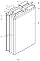
FIG. 1 is a three-dimensional schematic diagram of a battery cell module according to an implementation. -
FIG. 2 is an exploded schematic view of the battery cell module shown inFIG. 1 . -
FIG. 3 is an exploded schematic view of the battery cell module shown inFIG. 2 from another perspective. -
FIG. 4 is a schematic structural diagram of two adjacent battery cells. -
FIG. 5 is a three-dimensional schematic diagram of the bracket, the flexible circuit board, and the battery cell shown inFIG. 3 from a side perspective. -
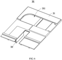
FIG. 6 is a three-dimensional schematic diagram of a bracket. -
FIG. 7 is a three-dimensional schematic diagram of a blocking panel. -
Battery cell module 1 Battery cell 10 First battery cell A Second battery cell B Third battery cell C Cell body 11 First tab 12 Second tab 13 Third tab 14 Fourth tab 15 Fifth tab 16 Sixth tab 17 Collection member 20 Body portion 21 Collection plate 22 Adapting member 25 Connection portion 251 Adapting end 252 Electrical connector 253 Bracket 30 Fixing plate 31 Groove 311 First barrier 32 Second barrier 33 First accommodating groove 34 Third barrier 35 Second accommodating groove 36 Connection member 40 First connection member 41 Security zone 411 Second connection member 42 Barrier plate 50 Blocking panel 60 Panel body 61 Opening 62 Restraint member 63 Through hole 64 First insulation member 70 Second insulation member 71 Third insulation member 72 Insulation plate 80 Adhesive 90 Circuit board 2 - The following describes the technical solutions in the embodiments of this application with reference to the accompanying drawings in the embodiments of this application. Apparently, the described embodiments are merely some but not all of the embodiments of this application.
- It should be noted that when considered to be "connected" to another component, a component may be directly connected to the another component or an intermediate component may exist. When considered to be "provided" on another component, a component may be directly provided on the another component or an intermediate component may exist at the same time. Terms such as "top", "bottom", "upper", "lower", "left", "right", "front", "rear" and similar expressions used herein are only for description purposes.
- Unless otherwise defined, all technical and scientific terms used herein shall have the same meanings as commonly understood by persons skilled in the art to which this application belongs. The terms used herein in this specification of this application are only used to describe specific embodiments, and are not intended to limit this application.
- A battery cell module is provided, and includes a plurality of stacked battery cells, a collection member, and a bracket. The battery cell includes tabs and a cell body; and the collection member is connected to the tabs, where in two adjacent battery cells, a first battery cell includes a first tab and a second tab, the second battery cell includes a third tab and a fourth tab, and the first tab is connected to the third tab. The bracket includes a fixing plate and a first barrier provided on the fixing plate, where the collection member is provided between the fixing plate and the cell body; and the first barrier is provided between the second tab of the first battery cell and the fourth tab of the second battery cell.
- The foregoing battery cell module is used as an example. The bracket is provided in the battery cell module, the bracket includes a first barrier, and the first barrier is provided between the unconnected second tab and fourth tab of the adjacent battery cells. That is, even if the battery cell module is intensively vibrated, by using the first barrier, the unconnected tabs of the adjacent battery cells may be prevented from coming into contact and causing a short circuit because of vibration or another condition.
- Referring to
FIG. 1 andFIG. 2 .abattery cell module 1 includes a plurality ofbattery cells 10, acollection member 20, and abracket 30. The plurality ofbattery cells 10 are stacked. Thebattery cell 10 includes acell body 11 and tabs connected to thecell body 11. The collection member is connected to the tabs. In twoadjacent battery cells 10, a first battery cell A includes afirst tab 12 and asecond tab 13, the second battery cell B includes athird tab 14 and afourth tab 15, and thefirst tab 12 is connected to thethird tab 14. Thebracket 30 includes afixing plate 31 and afirst barrier 32 provided on thefixing plate 31, where thecollection member 20 is disposed between thefixing plate 31 and thecell body 11; and thefirst barrier 32 is disposed between thesecond tab 13 of the first battery cell A and thefourth tab 15 of the second battery cell B. - In this implementation, the
collection member 20 is a flexible circuit board. It may be understood that, in another implementation, thecollection member 20 may also be replaced with another structure with an equivalent usage or function, such as a collection terminal. - Referring to
FIG. 2 ,FIG. 3 , andFIG. 4 , the plurality ofbattery cells 10 are stacked in a preset direction. In an implementation, thebattery cells 10 are disposed in a direction from top to bottom. Thebattery cell 10 includes thecell body 11 and tabs. In this implementation, the twoadjacent battery cells 10 are described. The two adjacent battery cells include a first battery cell A and a second battery cell B. The first battery cell A and the second battery cell B includecell bodies 11, and the first battery cell A further includes afirst tab 12 and asecond tab 13 provided on thecell body 11. The second battery cell B further includes athird tab 14 and afourth tab 15 provided on thecell body 11. A third battery cell C is further provided on a side of the second battery cell B away from the first battery cell A. The third battery cell C includes acell body 11 and afifth tab 16 and asixth tab 17 provided on thecell body 11. Thecell body 11 is formed by winding or laminating two electrode plates after a separator is provided therebetween. Such technical content is relatively frequently used in existing battery structures, and is not repeated herein. - In an implementation, the
first tab 12, thefourth tab 15, and thefifth tab 16 are positive tabs, and thesecond tab 13, thethird tab 14, and thesixth tab 17 are negative tabs. It may be understood that, in another implementation, polarities of thefirst tab 12 may be exchanged with polarities of thesecond tab 13, thefourth tab 15 may be exchanged with polarities of thethird tab 14, and thefifth tab 16 may be exchanged with polarities of thesixth tab 17. Between theadjacent battery cells 10, tab on onebattery cell 10 and tab on theother battery cell 10 are provided on the same side of theirrespective cell bodies 11, and the tabs are connected to connect a plurality of thebattery cells 10. Specifically, thefirst tab 12 of the first battery cell A is connected to thethird tab 14 of the second battery cell B, thefourth tab 15 of the second battery cell B is connected to thesixth tab 17 of the third battery cell C, and thefifth tab 16 extends away from thethird tab 14. A plurality ofother battery cells 10 are connected in the same manner to realize the foregoing serial connection of the plurality of thebattery cells 10. In this implementation, thefirst tab 12 and thethird tab 14 are connected through welding, and thefourth tab 15 and thesixth tab 17 are connected through welding. - Referring to
FIG. 2 andFIG. 3 , thecollection member 20 is disposed on a side of thebattery cell 10 on which the tabs are provided. Thecollection member 20 includes abody portion 21 and acollection plate 22 provided on thebody portion 21, and the tabs on theadjacent battery cells 10 are stacked with and then connected to thecollection plate 22, to collect a voltage. In an implementation, the tabs are welded to thecollection plate 22. - It may be understood that, in another implementation, the tabs may also be connected to the
collection plate 22 in another manner. For example, the tabs are locked onto thecollection plate 22 by using a screw. - A plurality of the
collection plates 22 are provided on thebody portion 21, and twoadjacent collection plates 22 perpendicular to thebody portion 21, and twoadjacent collection plates 22 extend in opposite directions , so that thecollection plates 22 are connected tofirst tabs 12,second tabs 13,third tabs 14,fourth tabs 15,fifth tabs 16, andsixth tabs 17 ondifferent battery cells 10. - Referring to
FIG. 2 andFIG. 3 , in an implementation, thebattery cell module 1 further includes an adaptingmember 25. The adaptingmember 25 includes aconnection portion 251 and an adaptingend 252. An end of theconnection portion 251 is connected to thebody portion 21 of thecollection member 20, and the other end of thecollection portion 251 is connected to the adaptingend 252. - The
connection portion 251 is roughly perpendicular to thebody portion 21, and theconnection portion 251 is provided along a surface of thecell body 11, to reduce an overall volume of thebattery cell module 1. - An
electrical connector 253 is also provided on the adaptingend 252, so that thecollection member 20 can be connected to an external electrical connection member, such as anexternal circuit board 2. - It may be understood that, in another implementation, the adapting
member 25 and thecollection member 20 may be an integrally formed structure. Similarly, thecollection member 20 may be connected to an external electrical connection member. - Referring to
FIG. 3 ,FIG. 5 , andFIG. 6 , thebracket 30 and thecollection member 20 are provided on the same side of thebattery cell 10, and thebracket 30 is provided on a side of thecollection member 20 away from thebattery cell 10. Thebracket 30 includes a fixingplate 31 and afirst barrier 32 provided on the fixingplate 31, and thefirst barrier 32 extends toward thebattery cell 10. Further, thefirst barrier 32 is a stop plate. - A
groove 311 is provided on a surface of the fixingplate 31 away from thefirst barrier 32, and thegroove 311 is configured to accommodate another structure. - In an implementation, the
first barrier 32 is provided between thesecond tab 13 and thefourth tab 15 of the adjacent first battery cell A and second battery cell B, so that the unconnectedsecond tab 13 andfourth tab 15 are electrically separated to avoid a short circuit. - In an implementation, the
bracket 30 further includes asecond barrier 33, and thesecond barrier 33 is provided on the fixingplate 31. The fixingplate 31, thefirst barrier 32, and thesecond barrier 33 form a firstaccommodating groove 34. Thefourth tab 15 and thesixth tab 17 are accommodated in the firstaccommodating groove 34. - In an implementation, the
bracket 30 further includes athird barrier 35, where thethird barrier 35 is also provided on the fixingplate 31, and thefirst barrier 32 is located between thethird barrier 35 and thesecond barrier 33. The fixingplate 31, thethird barrier 35, and thefirst barrier 32 form a secondaccommodating groove 36, and thethird barrier 35 and thefirst barrier 32 can jointly separate the unconnectedsecond tab 13 andfourth tab 15 of the adjacent first battery cell A and second battery cell B, to more effectively prevent the unconnectedsecond tab 13 andfourth tab 15 from coming into contact. - At least one of the
first barrier 32, thesecond barrier 33, and thethird barrier 35 includes an insulation structure (not shown). In this embodiment, the fixingplate 31, thefirst barrier 32, thesecond barrier 33, and thethird barrier 35 are integrally formed from plastic. In another embodiment, thefirst barrier 32 may be made of an uninsulated material. To electrically separate the unconnected tabs and avoid the short circuit, thefirst barrier 32 may be coated with an insulation material or an insulation member may be provided on the barrier. Similarly, thesecond barrier 33 and thethird barrier 35 may also be provided in this manner. In addition, an insulation member may be added between the tab and thefirst barrier 32 for electrical separation. - It may be understood that, in another implementation, a plurality of
first barriers 32 andsecond barriers 33 may be provided on thebracket 30 to accommodate the connected tabs and thecollection plates 22. A plurality ofthird barriers 35 may also be provided on thebracket 30 to cooperate with thefirst barrier 32 to jointly separate the unconnectedsecond tab 13 andfourth tab 15 of theadjacent battery cells 10. - In another implementation, it is possible that a
second tab 13 of one first battery cell A is separated from afourth tab 15 of a second battery cell B adjacent to the first battery cell A by providing only thefirst barrier 32. Such setting can make thebracket 30 simpler and have a lighter overall structure. - Referring to
FIG. 2 andFIG. 3 , thebattery cell module 1 further includes aconnection member 40, and theconnection member 40 is connected to a tab of thebattery cell 10. Theconnection member 40 includes afirst connection member 41 and asecond connection member 42. An end of thefirst connection member 41 is connected to the tab and thecollection plate 22 at a lowest end of thebattery cell 10, and the other end extends toward an upper end of thebattery cell 10. Thefirst connection member 41 is accommodated in thegroove 311 of thebracket 30, to prevent thefirst connection member 41 from shaking during highly intensive vibration. In addition, thebracket 30 also plays a role of supporting thefirst connection member 41. An end of thesecond connection member 42 is connected to the tab and thecollection plate 22 at the upper end of thebattery cell 10, and the other end extends away from the upper end of thebattery cell 10. Thefirst connection member 41 is connected to a positive tab on thebattery cell 10, and thesecond connection member 42 is connected to a negative tab on thebattery cell 10. It may be understood that, in another implementation, polarities of the tabs connected to thefirst connection member 41 and thesecond connection member 42 may be exchanged. - The
first connection member 41 is provided with asecurity zone 411. When a current is greater than a preset current, thefirst connection member 41 is disconnected in thesecurity zone 411, thereby the current disconnected and preventing a dangerous situation. In this case, thefirst connection member 41 in thesecurity zone 411 is equivalent to a fuse, thereby improving safety of a soft-packaged module of thebattery cell 10. - To prevent high temperature from affecting the
bracket 30 if thefirst connection member 41 is disconnected in thesecurity zone 411, abarrier plate 50 is provided in thesecurity zone 411. Further, twobarrier plates 50 are provided in thesecurity zone 411, and the twobarrier plates 50 are attached to two opposite surfaces of thefirst connection member 41, to insulate thefirst connection member 41 in thesecurity zone 411 from heat. - In an implementation, after extending toward the
battery cell 10 close to the rightmost side, thefirst connection member 41 is located on the same side of thebattery cell 10 as the other end of thesecond connection member 42, which can reduce an occupancy volume required when thefirst connection member 41 and thesecond connection member 42 extend out, thereby reducing the overall volume of thebattery cell module 1. - Referring to
FIG. 7 , thebattery cell module 1 further includes a blockingpanel 60. The blockingpanel 60 is provided on an outer surface of thebattery cell 10, to protect thebattery cell 10. The blockingpanel 60 includes apanel body 61, and a shape of thepanel body 61 is roughly the same as that of thecell body 11. Thepanel body 61 is provided with anopening 62 at a location close to an end of the tab, and the end of theconnection member 40 can extend through theopening 62. Further, thepanel body 61 is provided with twoopenings 62, the end of thefirst connection member 41 extends through oneopening 62, and the end of thesecond connection member 42 extends through theother opening 62. - In an implementation, the blocking
panel 60 further includes arestraint member 63, and therestraint member 63 is provided at theopening 62 and configured to restrain thefirst connection member 41 and thesecond connection member 42, to prevent ends of thefirst connection member 41 and thesecond connection member 42 from shaking at theopenings 62 during highly intensive vibration of thebattery cell module 1 and affecting a connection to another structure. Further, therestraint member 63 is a restraint column. - It may be understood that, in another implementation, the
restraint member 63 may also be a restraint bump, and when used to replace the restraint column, the restraint bump can also restrain locations of thefirst connection member 41 and thesecond connection member 42. - The
panel body 61 is also provided with a throughhole 64. After theconnection portion 251 of the adaptingmember 25 extends along a surface of thebattery cell 10 close to the blockingpanel 60, the adaptingend 252 can extend through the throughhole 64. Thefirst connection member 41 and thesecond connection member 42 extending through the throughholes 62, and the adaptingend 252 extending through the throughhole 64 are connected to acircuit board 2 provided on the surface of the blockingpanel 60. - Referring to
FIG. 2 ,FIG. 3 , andFIG. 5 , afirst insulation member 70 is provided in the firstaccommodating groove 34, and thefirst insulation member 70 is located between thefourth tab 15 and thesixth tab 17. That is, thefirst insulation member 70 can be provided between the connected tabs on theadjacent battery cells 10. - The
second insulation member 71 is provided in the secondaccommodating groove 36, and thesecond insulation member 71 separates the unconnectedsecond tab 13 andfourth tab 15 of the adjacent first battery cell A and second battery cell B, and may cooperate with thefirst barrier 32 to prevent the unconnectedsecond tab 13 andfourth tab 15 from coming into contact. - A
third insulation member 72 is provided between theadjacent battery cells 10, and thethird insulation member 72 can deform after being pressed when thebattery cells 10 expand, thereby preventing thebattery cells 10 from pressing the housing. Specifically, thethird insulation member 72 is provided between twoadjacent cell bodies 11. Further, to better protect thebattery cell module 1, an insulation member (not marked in the figure) is provided on each periphery of stackedbattery cells 10. When collision occurs, the insulation member can serve as a buffer for thebattery cells 10. - Further, an
insulation plate 80 is provided on thethird insulation member 72 between the blockingpanel 60 and thebattery cell 10, and theinsulation plate 80 is located between the blockingpanel 60 and thethird insulation member 72. The adaptingend 252 is fixed to theinsulation plate 80 through adhesion, so that the end of the adaptingmember 25 is fixed, to avoid shaking. - In an implementation, the
first insulation member 70, thesecond insulation member 71, thethird insulation member 72, and the insulation member provided on the periphery of the stackedbattery cells 10 are foam. It may be understood that, in another implementation, the insulation member may also be replaced with another structure with an equivalent usage or function. - Referring to
FIG. 2 andFIG. 3 again, thebattery cell module 1 further includes an adhesive 90. The adhesive 90 is provided on the periphery of the stackedbattery cells 10, to protect thebattery cells 10. In an implementation, the stackedbattery cells 10 can be placed in an apparatus, the flowingadhesive 90 can be filled from theopening 62 of the blockingpanel 60, and after the adhesive 90 is stabilized into a form, thebattery cell 10 is extracted. - The
first insulation member 70 and thesecond insulation member 71 are respectively provided in the firstaccommodating groove 34 and the secondaccommodating groove 36, and can be filled at a location at which the adhesive 90 originally needs to be filled, thereby reducing overall weight of thebattery cell module 1. - In another implementation, a battery pack is further related (not shown in the figure). The battery pack includes a housing (not shown in the figure) and the
battery cell module 1 in the foregoing implementation. Thebattery cell module 1 is accommodated in the housing, and the adhesive 90 is located between thebattery cell 10 and the housing. The battery uses the foregoingbattery cell module 1, and therefore has corresponding beneficial effects. Details are not described herein. - In conclusion, the
battery cell module 1 provided in the implementations of this application can replace an adapting plate in the original module by using thecollection member 20 and thebracket 30. Thecollection member 20 is connected to the tabs, which can effectively reduce a pulling force on the tab. Thebracket 30 includes afirst barrier 32, which can electrically separate the unconnectedsecond tab 13 andfourth tab 15, to prevent the unconnectedsecond tab 13 andfourth tab 15 from coming into contact and causing a short circuit. Thebattery cell module 1 is used in some smart home apparatuses, such as a robotic vacuum cleaner, a vacuum cleaner, and a circular saw cutting machine. Even when highly intensively vibrated, the unconnectedsecond tab 13 andfourth tab 15 do not come into contact. Furthermore, thebracket 30 is light in weight and low in cost, so that weight of thebattery cell module 1 is reduced, and cost required in the assembly process is reduced. - In addition, persons of ordinary skills in the art should recognize that the foregoing implementations are only intended to illustrate, but not to limit this application, and appropriate changes and modifications made to the foregoing embodiments without departing from the substantial spirit and scope of this application fall within the claimed scope of this application.
Claims (12)
- A battery cell module, comprising:a plurality of stacked battery cells, wherein the battery cell comprises tabs and a cell body; anda collection member, connected to the tabs;wherein in two adjacent battery cells, a first battery cell comprises a first tab and a second tab, the second battery cell comprises a third tab and a fourth tab, and the first tab is connected to the third tab; andcharacterized in that the battery cell module further comprises:a bracket, comprising a fixing plate and a first barrier provided on the fixing plate,wherein the collection member is provided between the fixing plate and the cell body; andthe first barrier is provided between the second tab of the first battery cell and the fourth tab of the second battery cell.
- The battery cell module according to claim 1, characterized in that the bracket further comprises a second barrier provided on the fixing plate, and the fixing plate, the first barrier, and the second barrier form a first accommodating groove;a third battery cell is provided on a side of the second battery cell, the third battery cell comprises a fifth tab and a sixth tab, the fourth tab is connected to the sixth tab, and the fifth tab extends in a direction away from the third tab; andthe fourth tab and the sixth tab are accommodated in the first accommodating groove, and the fourth tab and the sixth tab are connected to the collection member.
- The battery cell module according to claim 2, characterized in that a first insulation member is provided between the fourth tab and the sixth tab.
- The battery cell module according to claim 2, characterized in that the bracket further comprises a third barrier provided on the fixing plate, the first barrier is located between the second barrier and the third barrier, the fixing plate, the third barrier, and the first barrier form a second accommodating groove, and a second insulation member is provided in the second accommodating groove.
- The battery cell module according to claim 4, characterized in that at least one of the first barrier, the second barrier, and the third barrier comprises an insulation structure.
- The battery cell module according to claim 4, characterized in that the battery cell module further comprises a connection member, an end of the connection member is connected to the battery cell, the other end of the connection member extends along a surface of the fixing plate away from the collection member, and the fixing plate is provided with a groove for accommodating the collection member.
- The battery cell module according to claim 6, characterized in that the battery cell module further comprises a blocking panel, the blocking panel is provided with an opening, and the other end of the collection member extends through the opening.
- The battery cell module according to claim 7, characterized in that a restraint member is provided at an opening location, and the restraint member is configured to restrain the connection member.
- The battery cell module according to claim 7, characterized in that the battery cell module further comprises an adapting member, wherein the adapting member comprises a connection portion and an adapting end, an end of the connection portion is connected to the collection member, the other end of the connection portion is connected to the adapting end, the blocking panel is further provided with a through hole, and the adapting end extends through the through hole.
- The battery cell module according to claim 1, characterized in that the battery cell module further comprises a third insulation member, and the third insulation member is provided between adjacent battery cells.
- The battery cell module according to claim 2, characterized in that the first tab, the fourth tab, and the fifth tab are positive tabs, the second tab, the third tab, and the sixth tab are negative tabs, and the plurality of battery cells are connected in series.
- A battery pack, characterized in that the battery pack comprises the battery cell module according to any one of claims 1 to 11 and a housing, and the battery cell module is accommodated in the housing.
Applications Claiming Priority (1)
| Application Number | Priority Date | Filing Date | Title |
|---|---|---|---|
| PCT/CN2020/102790 WO2022011705A1 (en) | 2020-07-17 | 2020-07-17 | Cell module and battery pack |
Publications (2)
| Publication Number | Publication Date |
|---|---|
| EP3965223A1 true EP3965223A1 (en) | 2022-03-09 |
| EP3965223A4 EP3965223A4 (en) | 2022-03-09 |
Family
ID=79292875
Family Applications (1)
| Application Number | Title | Priority Date | Filing Date |
|---|---|---|---|
| EP20866917.6A Pending EP3965223A4 (en) | 2020-07-17 | 2020-07-17 | MODULE OF ELEMENTS AND BATTERY PACK |
Country Status (4)
| Country | Link |
|---|---|
| US (1) | US12021270B2 (en) |
| EP (1) | EP3965223A4 (en) |
| CN (1) | CN115088130B (en) |
| WO (1) | WO2022011705A1 (en) |
Cited By (2)
| Publication number | Priority date | Publication date | Assignee | Title |
|---|---|---|---|---|
| JP2024081613A (en) * | 2022-12-06 | 2024-06-18 | ミルウォーキー エレクトリック ツール コーポレイション | Battery pack |
| EP4687203A1 (en) * | 2024-07-31 | 2026-02-04 | Eve Energy Co., Ltd. | Battery module and battery pack |
Family Cites Families (25)
| Publication number | Priority date | Publication date | Assignee | Title |
|---|---|---|---|---|
| JP5537111B2 (en) * | 2009-09-30 | 2014-07-02 | 株式会社東芝 | Secondary battery device |
| US9356278B2 (en) * | 2011-03-31 | 2016-05-31 | Nec Energy Devices, Ltd. | Battery pack |
| JP2015187914A (en) * | 2012-08-09 | 2015-10-29 | 三洋電機株式会社 | Power supply device, and electrically driven vehicle and power storage device having the same |
| KR101736377B1 (en) * | 2014-06-09 | 2017-05-16 | 주식회사 엘지화학 | Battery module and battery pack including the same |
| CN204596909U (en) | 2015-03-25 | 2015-08-26 | 深圳金山电池有限公司 | A kind of Novel button lithium ion battery |
| CN108352489B (en) * | 2015-10-22 | 2020-06-02 | 远景Aesc日本有限公司 | Battery pack and method for manufacturing the same |
| CN205122683U (en) * | 2015-11-02 | 2016-03-30 | 青海时代新能源科技有限公司 | Group battery equipment is with preventing short circuit frock |
| EP3226342B1 (en) * | 2016-04-01 | 2020-12-16 | Samsung SDI Co., Ltd. | Cell connection unit |
| CN205882078U (en) * | 2016-08-10 | 2017-01-11 | 中山市电赢科技有限公司 | Assembly structure of a lithium battery |
| CN106299166B (en) * | 2016-09-20 | 2020-02-11 | 宁德时代新能源科技股份有限公司 | Battery pack |
| DE102017219316A1 (en) | 2017-10-27 | 2019-05-02 | Robert Bosch Gmbh | Battery cell and method for producing such |
| CN207743308U (en) * | 2018-01-31 | 2018-08-17 | 宁德时代新能源科技股份有限公司 | Battery modules |
| JP2019186037A (en) * | 2018-04-10 | 2019-10-24 | カルソニックカンセイ株式会社 | Battery module |
| WO2020037535A1 (en) | 2018-08-22 | 2020-02-27 | 珠海微矩实业有限公司 | Miniature battery |
| CN110800129A (en) * | 2018-08-31 | 2020-02-14 | 深圳市大疆创新科技有限公司 | Battery and agricultural drone with the same |
| CN109888159A (en) * | 2019-02-28 | 2019-06-14 | 力神动力电池系统有限公司 | A kind of power battery Soft Roll mould group |
| CN209860094U (en) | 2019-03-28 | 2019-12-27 | 武汉嘉晨汽车技术有限公司 | Battery package open circuit unit who contains FPC flexbile plate |
| EP3736873A1 (en) * | 2019-05-10 | 2020-11-11 | Andreas Stihl AG & Co. KG | Battery pack, processing system and method for producing a battery pack |
| CN210129547U (en) * | 2019-06-17 | 2020-03-06 | 东莞新能源科技有限公司 | Battery pack and electrochemical device |
| CN210092187U (en) * | 2019-08-08 | 2020-02-18 | 东莞新能源科技有限公司 | Battery pack |
| CN110993873B (en) | 2019-12-28 | 2023-10-03 | 广州宝狮新能源有限公司 | Soft package cell assembly device, soft package cell module and method for assembling soft package cell module |
| CN111009625A (en) | 2019-12-30 | 2020-04-14 | 广东微电新能源有限公司 | Energy storage device |
| CN113557630A (en) | 2020-02-07 | 2021-10-26 | 宁德新能源科技有限公司 | Battery and electric device with same |
| CN111403637A (en) | 2020-03-30 | 2020-07-10 | 珠海冠宇电池有限公司 | A case structure and battery |
| CN212366143U (en) * | 2020-07-17 | 2021-01-15 | 东莞新能安科技有限公司 | Battery cell module and battery pack |
-
2020
- 2020-07-17 WO PCT/CN2020/102790 patent/WO2022011705A1/en not_active Ceased
- 2020-07-17 CN CN202080096213.2A patent/CN115088130B/en active Active
- 2020-07-17 EP EP20866917.6A patent/EP3965223A4/en active Pending
-
2021
- 2021-03-31 US US17/219,832 patent/US12021270B2/en active Active
Cited By (3)
| Publication number | Priority date | Publication date | Assignee | Title |
|---|---|---|---|---|
| JP2024081613A (en) * | 2022-12-06 | 2024-06-18 | ミルウォーキー エレクトリック ツール コーポレイション | Battery pack |
| EP4383417A3 (en) * | 2022-12-06 | 2024-08-07 | Milwaukee Electric Tool Corporation | Battery pack |
| EP4687203A1 (en) * | 2024-07-31 | 2026-02-04 | Eve Energy Co., Ltd. | Battery module and battery pack |
Also Published As
| Publication number | Publication date |
|---|---|
| US20220021091A1 (en) | 2022-01-20 |
| CN115088130B (en) | 2025-09-09 |
| US12021270B2 (en) | 2024-06-25 |
| WO2022011705A1 (en) | 2022-01-20 |
| CN115088130A (en) | 2022-09-20 |
| EP3965223A4 (en) | 2022-03-09 |
Similar Documents
| Publication | Publication Date | Title |
|---|---|---|
| EP2064759B1 (en) | Battery module interface | |
| JP5394522B2 (en) | Separating type connecting member for manufacturing secondary battery module and method for improving battery module performance by voltage leveling | |
| US8956751B2 (en) | Battery pack and battery module having the same | |
| US7393608B2 (en) | Rechargeable battery and battery module using the same | |
| CN212366143U (en) | Battery cell module and battery pack | |
| CN110114932B (en) | Battery modules and battery packs and vehicles including battery modules | |
| EP3154108B1 (en) | Battery module and battery pack including same | |
| CN104377339A (en) | rechargeable battery pack | |
| EP3940867B1 (en) | Battery pack with enhanced structure for preventing short circuit and shock | |
| KR20200069720A (en) | Battery module including insert injection molded busbar | |
| KR102646201B1 (en) | Wiring harness separator assemblies, battery modules, battery packs and devices | |
| US12021270B2 (en) | Battery cell module and battery pack | |
| CN117855697A (en) | Prismatic secondary battery including discharge unit | |
| CN117321842A (en) | Battery pack and vehicle including the same | |
| KR20200108714A (en) | Inter connect board assembly and battery module including the same | |
| EP4224595A1 (en) | Battery pack | |
| KR100649562B1 (en) | Battery module | |
| EP4432437A1 (en) | Battery pack | |
| KR102371373B1 (en) | Battery module | |
| US12362436B2 (en) | Power storage device | |
| CN117219952A (en) | Electric storage device | |
| EP4447204A1 (en) | Rechargeable battery module | |
| EP4675802A1 (en) | Battery module and battery pack and vehicle including same | |
| KR102673552B1 (en) | battery module for eco-friendly vehicle and ventilation bracket applied to thereof | |
| KR102931668B1 (en) | Bus Bar and Battery Module Including The Same, and Battery Pack |
Legal Events
| Date | Code | Title | Description |
|---|---|---|---|
| STAA | Information on the status of an ep patent application or granted ep patent |
Free format text: STATUS: UNKNOWN |
|
| STAA | Information on the status of an ep patent application or granted ep patent |
Free format text: STATUS: THE INTERNATIONAL PUBLICATION HAS BEEN MADE |
|
| PUAI | Public reference made under article 153(3) epc to a published international application that has entered the european phase |
Free format text: ORIGINAL CODE: 0009012 |
|
| STAA | Information on the status of an ep patent application or granted ep patent |
Free format text: STATUS: REQUEST FOR EXAMINATION WAS MADE |
|
| 17P | Request for examination filed |
Effective date: 20210329 |
|
| A4 | Supplementary search report drawn up and despatched |
Effective date: 20211115 |
|
| AK | Designated contracting states |
Kind code of ref document: A1 Designated state(s): AL AT BE BG CH CY CZ DE DK EE ES FI FR GB GR HR HU IE IS IT LI LT LU LV MC MK MT NL NO PL PT RO RS SE SI SK SM TR |
|
| DAV | Request for validation of the european patent (deleted) | ||
| DAX | Request for extension of the european patent (deleted) | ||
| STAA | Information on the status of an ep patent application or granted ep patent |
Free format text: STATUS: EXAMINATION IS IN PROGRESS |
|
| 17Q | First examination report despatched |
Effective date: 20240531 |
|
| RAP1 | Party data changed (applicant data changed or rights of an application transferred) |
Owner name: NINGDE AMPEREX TECHNOLOGY LTD. |