EP3965135B1 - Magnetic latching relay capable of accurately positioning magnetic circuit - Google Patents
Magnetic latching relay capable of accurately positioning magnetic circuit Download PDFInfo
- Publication number
- EP3965135B1 EP3965135B1 EP21193270.2A EP21193270A EP3965135B1 EP 3965135 B1 EP3965135 B1 EP 3965135B1 EP 21193270 A EP21193270 A EP 21193270A EP 3965135 B1 EP3965135 B1 EP 3965135B1
- Authority
- EP
- European Patent Office
- Prior art keywords
- positioning
- magnetic circuit
- base
- bobbin
- latching relay
- Prior art date
- Legal status (The legal status is an assumption and is not a legal conclusion. Google has not performed a legal analysis and makes no representation as to the accuracy of the status listed.)
- Active
Links
Images







Classifications
-
- H—ELECTRICITY
- H01—ELECTRIC ELEMENTS
- H01F—MAGNETS; INDUCTANCES; TRANSFORMERS; SELECTION OF MATERIALS FOR THEIR MAGNETIC PROPERTIES
- H01F7/00—Magnets
- H01F7/06—Electromagnets; Actuators including electromagnets
- H01F7/08—Electromagnets; Actuators including electromagnets with armatures
- H01F7/126—Supporting or mounting
-
- H—ELECTRICITY
- H01—ELECTRIC ELEMENTS
- H01H—ELECTRIC SWITCHES; RELAYS; SELECTORS; EMERGENCY PROTECTIVE DEVICES
- H01H50/00—Details of electromagnetic relays
- H01H50/14—Terminal arrangements
-
- H—ELECTRICITY
- H01—ELECTRIC ELEMENTS
- H01H—ELECTRIC SWITCHES; RELAYS; SELECTORS; EMERGENCY PROTECTIVE DEVICES
- H01H50/00—Details of electromagnetic relays
- H01H50/02—Bases; Casings; Covers
- H01H50/04—Mounting complete relay or separate parts of relay on a base or inside a case
- H01H50/041—Details concerning assembly of relays
- H01H50/042—Different parts are assembled by insertion without extra mounting facilities like screws, in an isolated mounting part, e.g. stack mounting on a coil-support
-
- H—ELECTRICITY
- H01—ELECTRIC ELEMENTS
- H01H—ELECTRIC SWITCHES; RELAYS; SELECTORS; EMERGENCY PROTECTIVE DEVICES
- H01H50/00—Details of electromagnetic relays
- H01H50/16—Magnetic circuit arrangements
-
- H—ELECTRICITY
- H01—ELECTRIC ELEMENTS
- H01H—ELECTRIC SWITCHES; RELAYS; SELECTORS; EMERGENCY PROTECTIVE DEVICES
- H01H50/00—Details of electromagnetic relays
- H01H50/16—Magnetic circuit arrangements
- H01H50/18—Movable parts of magnetic circuits, e.g. armature
- H01H50/32—Latching movable parts mechanically
-
- H—ELECTRICITY
- H01—ELECTRIC ELEMENTS
- H01H—ELECTRIC SWITCHES; RELAYS; SELECTORS; EMERGENCY PROTECTIVE DEVICES
- H01H50/00—Details of electromagnetic relays
- H01H50/16—Magnetic circuit arrangements
- H01H50/36—Stationary parts of magnetic circuit, e.g. yoke
-
- H—ELECTRICITY
- H01—ELECTRIC ELEMENTS
- H01H—ELECTRIC SWITCHES; RELAYS; SELECTORS; EMERGENCY PROTECTIVE DEVICES
- H01H50/00—Details of electromagnetic relays
- H01H50/54—Contact arrangements
- H01H50/56—Contact spring sets
- H01H50/58—Driving arrangements structurally associated therewith; Mounting of driving arrangements on armature
-
- H—ELECTRICITY
- H01—ELECTRIC ELEMENTS
- H01H—ELECTRIC SWITCHES; RELAYS; SELECTORS; EMERGENCY PROTECTIVE DEVICES
- H01H50/00—Details of electromagnetic relays
- H01H50/64—Driving arrangements between movable part of magnetic circuit and contact
-
- H—ELECTRICITY
- H01—ELECTRIC ELEMENTS
- H01H—ELECTRIC SWITCHES; RELAYS; SELECTORS; EMERGENCY PROTECTIVE DEVICES
- H01H51/00—Electromagnetic relays
- H01H51/01—Relays in which the armature is maintained in one position by a permanent magnet and freed by energisation of a coil producing an opposing magnetic field
Definitions
- the present disclosure relates to a magnetic latching relay; more particularly, the present disclosure relates to a magnetic latching relay capable of accurately positioning a magnetic circuit.
- the structure of the existing magnetic latching relay consists of a magnetic circuit system, a contact system, a pushing mechanism and a base.
- the magnetic circuit system generally consists of two substantially symmetrical magnetic circuits, including a stationary magnetizer component, a movable magnetizer component and a coil.
- the contact system includes a movable spring portion and a static spring portion.
- the pushing mechanism is generally implemented by a pushing block, and the pushing mechanism is connected between the movable magnetizer component and the movable spring portion.
- the main application area of magnetic latching relay is power metering, and the main functions are switching and metering.
- the main functions are switching and metering.
- magnetic latching relay is required to withstand and conduct short-circuit current. According to the operating characteristics of the power grid and based on the consideration of personal and equipment safety, the magnetic latching relay has three working conditions against short-circuit current.
- Working condition I the front end of the electric meter (upstream grid) is short-circuited, characterized in that the contact of the magnetic latching relay is closed (the meter is in closed state), and the short-circuit current is large.
- the short-circuit current here is called “safety short-circuit current to withstand”, and the requirement for the magnetic latching relay to withstand short-circuit current is, when or after being subject to the short-circuit current, "no explosion, no ignition, splash free”.
- Working condition II the back end of the electric meter (downstream grid) is short-circuited, characterized in that the contact of the magnetic latching relay is closed (the meter is in closed state), and the short-circuit current is small.
- the short-circuit current here is called “functional short-circuit current to withstand”, and the magnetic latching relay is required to be “functionally normal” after being subject to the short-circuit current.
- Working condition III the back end of the meter (downstream of the grid) is short-circuited, characterized in that the contact of the magnetic latching relay is open (the meter is in open state), and the short-circuit current is small.
- the short-circuit current here is called “functionally conducted short-circuit current”, and the magnetic latching relay is required to be “functionally normal” after conducting the short-circuit current.
- the short-circuit current varies greatly.
- the "safety short-circuit current to withstand" of the IEC62055-31 standard UC2 grade is 4.5KA, which is 1.8 times of "functional short-circuit current to withstand” or “functionally conducted short-circuit current” of 2.5KA.
- the "safety short-circuit current to withstand" of UC3 grade is 6KA, which is twice of the "functional short-circuit current to withstand” or “functionally conducted short-circuit current” of 3KA.
- ANSI C12.1 standard 200A rated current level "safety short-circuit current to withstand" has a peak of 24KA, which is 3.4 times of the peak value of 7KA of "functional short-circuit current to withstand".
- Document EP 2 911 174 A1 provides a contact terminal assembling structure free from malfunction or variation in operating characteristic.
- Movable contact plate assembly is fixed to one end of movable contact terminal by using swaging projection.
- One end of the movable contact terminal is supported by pressing it into groove of base.
- the rear edge of the one end of the movable contact plate assembly has at least one a fitting projection which projects beyond the swaging projection in condition where the contact terminal is inserted in the groove.
- the present invention provides a magnetic latching relay capable of accurately positioning a magnetic circuit as defined by claim 1.
- Optional features are defined by the dependent claims.
- a magnetic latching relay capable of accurately positioning a magnetic circuit of the present embodiment includes a magnetic circuit portion and a base 8.
- the magnetic circuit portion includes a yoke 91, a core 92, an armature (not shown), and a bobbin 94.
- the iron core 92 is inserted into a through-hole 941 of the bobbin 94, and the yoke 91 comprises two yokes, and one side 911 of each of the two yokes 91 is connected to the iron core 92 respectively at the both ends of the through-hole 941 of the bobbin and.
- the armature is fitted between the other side 912 of each of the two yokes 91.
- the magnetic circuit portion is mounted on the base 8, with the axis of the through-hole 941 of the bobbin in a horizontal manner.
- a positioning convex portion 9111 is further provided on the outward face of the side 911 of the yokes.
- Positioning grooves 84 are formed in the side walls 83 of the base 8 corresponding to the ends of the through holes of the bobbin, respectively, to be engaged with the positioning convex portion 9111 of the yokes to realize the positioning of the magnetic circuit portions on the base 8 in the horizontal direction perpendicular to the axis of the bobbin through hole 941.
- the positioning groove 84 of the side wall of the base has an elongated shape, and the longitudinal direction of the positioning groove 84 is disposed along the vertical direction.
- the positioning groove 84 of the side wall 83 of one side of the base is formed by two outwardly protruding ribs 85 of the side wall.
- the positioning groove of the side wall 83 of the other side base is formed by an inwardly recessed structure of the side wall.
- the portion of positioning groove 84 surrounded by the ribs 85 is an end corresponding to the coil head, and the coil is provided with a coil pin at the end.
- the recessed structure is formed at an end corresponding to the tail of the coil, and the coil has no coil pins at this end.
- the positioning convex portion 9111 of the yoke is composed of two cylinders which are arranged in the vertical direction.
- the bottom end faces 942, 943 of the two ends of the bobbin 94 and the bottom end faces 9121, 9122 of the other sides 912 of the two yokes are mounted as mounting faces on the inner surface of the base 8.
- a boss for positioning is further disposed among a bottom end surface of both ends of the bobbin, a bottom end surface of each of the other sides of the two yokes, and a corresponding position of the inner surface of the base to realize the positioning of the magnetic circuit portion on the base 8 in a downward direction in the vertical direction perpendicular to the axis of the bobbin through hole.
- the positioning bosses are respectively protruded upward along the inner surface of the base at positions corresponding to the bottom end faces of two ends of the bobbin and the bottom end faces of the other sides of the two yokes. That is, the inner surface of the base 8 is provided with a positioning boss 86 at a mounting portion corresponding to the bottom end surface 942 of the head of the bobbin 94, and the inner surface of the base 8 is provided with a positioning boss 87 at a mounting portion corresponding to the bottom end surface 943 of the tail of the bobbin 94.
- the bottom end surface 9121 of the inner surface of the base 8 corresponding to the other side 912 of one yoke is provided with a positioning boss 88, and the bottom end surface 9122 of the inner surface of the base 8 corresponding to the other side 912 of the other yoke is provided with a positioning boss 89. Since the bobbin 94, the mounting surface of the yoke 91, and the mounting surface of the base 8 are mounted by small-surface contact, the verticality after assembly can be improved.
- a magnetically permeable member that passes a through hole of a bobbin is generally referred to as an iron core
- a magnetically permeable member disposed outside the through hole of the bobbin is referred to as a yoke
- a movable magnetically permeable member is referred to as an armature.
- the magnetic core, the yoke and the armature constitute a magnetic circuit
- the iron core and the yoke can be separate components, such as the structure described in this embodiment, that is, a straight-shaped iron core and two L-shaped yokes, i.e., three components in total.
- the iron core and the yoke may also be integrally connected; for example, the iron core and one of the yokes are integrally formed, a U-shaped structure is formed by bending, and the other yoke is still L-shaped, i.e., two components in total.
- the iron core and the two yokes are integrated into one body, and an integral part of a C-shaped structure is formed by bending, thus the structure is one-piece.
- two iron cores are stacked in the through hole of the bobbin, and the two iron cores are respectively integrated with the two yokes, so that two U-shaped structures can be formed by bending, and each side of the two U-shaped structures is inserted into the through hole of the bobbin to form a stacked core, i.e., two components in total.
- two yokes 91 are used.
- a positioning convex portion 9111 is disposed on an outwardly face of one side 911 of the yoke 91; in the side wall 83 of the base 8 corresponding to two ends of the through hole 941 of the bobbin, a positioning groove 84 is provided which can cooperate with the positioning convex portion 9111 of the yoke, thereby, realizing the positioning of the magnetic circuit portion on the base 8 in a horizontal direction perpendicular to the axis of the bobbin through hole 941.
- a boss for positioning (that is, the inside of the base 8) is disposed among the bottom end faces of the two ends of the bobbin, the bottom end faces of the other sides of the two yokes, and the corresponding positions of the inner surfaces of the bases, (the bottom end face 942 of the inner surface of the base 8 corresponding to the head portion of the bobbin 94 is provided with a positioning boss 86, the bottom end face 943 of the inner surface of the base 8 corresponding to the tail portion of the bobbin 94 is provided with a positioning boss 87, the bottom end face 9121 of the inner surface of the base 8 corresponding to the other side 912 of one yoke is provided with a positioning boss 88, and the bottom end face 9122 of the inner surface of the base 8 corresponding to the other side 912 of the other yoke is provided with a positioning boss 89).
- the positioning of the magnetic circuit portion on the base in a downward direction in the vertical direction perpendicular to the axis of the coil frame through-hole can be achieved.
- the structure of the embodiment can ensure that the assembly accuracy of the perpendicularity of the magnetic circuit portion is not affected by the flatness of the bottom surface of the base after the base is installed, and the perpendicularity of the magnetic circuit portion after assembling can be within 0.05 mm.
- auxiliary positioning technologies such as dispensing, which eliminates the disadvantages that using a glue bond easily contaminates the working portion of the magnetic circuit portion, thus the production efficiency is greatly improved.
- a magnetic latching relay capable of accurately positioning a magnetic circuit of the present embodiment differs from Embodiment 1 in that the positioning boss is disposed at the bobbin and the yoke, and the positioning bosses are respectively formed to protrude downward along the bottom end faces of two ends of the bobbin 94 and the bottom end faces of the other sides 912 of the two yokes 91.
- positioning bosses are disposed, wherein the positioning boss 944 is disposed at the bottom end face 942 of the head of the bobbin 94, the positioning boss 945 is disposed at the bottom end face 943 of the tail of the bobbin 94, the positioning boss 913 is disposed at the bottom end face 9121 of the other side 912 of one yoke, and the positioning boss 914 is disposed at the bottom end face 9222 of the other side 912 of the other yoke.
- a magnetic latching relay capable of accurately positioning a magnetic circuit of the present embodiment differs from the Embodiment 2 in that the positioning convex portion 9111 of the yoke 91 is composed of a rectangular parallelepiped, the length direction of which is along the vertical direction.
- At least one yoke of the two yokes is provided with a positioning convex portion on the outward side of one side of the yoke
- at least one side wall of the side walls of two ends of the base corresponding to the through hole of the bobbin is provided with a positioning groove that can cooperate with the positioning convex portion of the yoke.
- the embodiment of the invention also adopts a boss for positioning among the bottom end faces of the two ends of the bobbin, the bottom end faces of the other sides of the two yokes, and the corresponding positions of the inner surfaces of the bases to realize the magnetic circuit portion being positioned on the base in the downward direction of the vertical direction perpendicular to the axis of the through hole of the coil frame. Therefore, it can be ensured that the assembly accuracy of the verticality of the magnetic circuit portion after being mounted in the base is not affected by the flatness of the bottom surface of the base, and the perpendicularity of the magnetic circuit portion after assembly can be within 0.05 mm. Other auxiliary positioning technologies such as dispensing are not required. The disadvantages of using a glue bond to easily contaminate the working portion of the magnetic circuit portion are eliminated, which greatly improves the production efficiency.
Landscapes
- Physics & Mathematics (AREA)
- Electromagnetism (AREA)
- Engineering & Computer Science (AREA)
- Power Engineering (AREA)
- Electromagnets (AREA)
- Burglar Alarm Systems (AREA)
Description
- The present disclosure relates to a magnetic latching relay; more particularly, the present disclosure relates to a magnetic latching relay capable of accurately positioning a magnetic circuit.
- The structure of the existing magnetic latching relay consists of a magnetic circuit system, a contact system, a pushing mechanism and a base. The magnetic circuit system generally consists of two substantially symmetrical magnetic circuits, including a stationary magnetizer component, a movable magnetizer component and a coil. The contact system includes a movable spring portion and a static spring portion. The pushing mechanism is generally implemented by a pushing block, and the pushing mechanism is connected between the movable magnetizer component and the movable spring portion. When positive pulse voltage is applied to the relay coil, the magnetic circuit system operates and the pushing block pushes the movable spring portion to make the contact closed, and thus the relay operates. When reverse pulse voltage is applied to the coil, the magnetic circuit system operates and the block pushes the movable spring portion to make the contact disconnected, and thus the relay is reset.
- The main application area of magnetic latching relay is power metering, and the main functions are switching and metering. With the continuous deepening of power grid reforms in various countries around the world, cases of electric meter explosions and fires caused by short-circuit currents have occurred, causing huge personal safety problems and property losses. Therefore, the world's major power companies, electric meter companies have proposed relevant standards or have introduced industry standards, to standardize the ability of magnetic latching relay to resist short-circuit current, so as to improve the safety of smart meter operation. In order to ensure personal safety and safety of electrical equipment, magnetic latching relay is required to withstand and conduct short-circuit current. According to the operating characteristics of the power grid and based on the consideration of personal and equipment safety, the magnetic latching relay has three working conditions against short-circuit current.
- Working condition I: the front end of the electric meter (upstream grid) is short-circuited, characterized in that the contact of the magnetic latching relay is closed (the meter is in closed state), and the short-circuit current is large. The short-circuit current here is called "safety short-circuit current to withstand", and the requirement for the magnetic latching relay to withstand short-circuit current is, when or after being subject to the short-circuit current, "no explosion, no ignition, splash free".
- Working condition II: the back end of the electric meter (downstream grid) is short-circuited, characterized in that the contact of the magnetic latching relay is closed (the meter is in closed state), and the short-circuit current is small. The short-circuit current here is called "functional short-circuit current to withstand", and the magnetic latching relay is required to be "functionally normal" after being subject to the short-circuit current.
- Working condition III: the back end of the meter (downstream of the grid) is short-circuited, characterized in that the contact of the magnetic latching relay is open (the meter is in open state), and the short-circuit current is small. The short-circuit current here is called "functionally conducted short-circuit current", and the magnetic latching relay is required to be "functionally normal" after conducting the short-circuit current.
- Under the three working conditions, the short-circuit current varies greatly. As an example, the "safety short-circuit current to withstand" of the IEC62055-31 standard UC2 grade is 4.5KA, which is 1.8 times of "functional short-circuit current to withstand" or "functionally conducted short-circuit current" of 2.5KA. The "safety short-circuit current to withstand" of UC3 grade is 6KA, which is twice of the "functional short-circuit current to withstand" or "functionally conducted short-circuit current" of 3KA. As another example, ANSI C12.1 standard 200A rated current level "safety short-circuit current to withstand" has a peak of 24KA, which is 3.4 times of the peak value of 7KA of "functional short-circuit current to withstand".
- Document
EP 2 911 174 A1 provides a contact terminal assembling structure free from malfunction or variation in operating characteristic. Movable contact plate assembly is fixed to one end of movable contact terminal by using swaging projection. One end of the movable contact terminal is supported by pressing it into groove of base. The rear edge of the one end of the movable contact plate assembly has at least one a fitting projection which projects beyond the swaging projection in condition where the contact terminal is inserted in the groove. - It is an object of the present invention to overcome the deficiencies of the prior art and to provide a magnetic latching relay in which a contact portion is provided with anti-scraping and is accurately positioned. By means of improvement of the cooperating structure between the insertion portion of the contact portion and the base slot, scraping can be prevented, and the precise positioning of the contact portion in the base can be ensured, thereby realizing a dual design of anti-scrapping and positioning in a small space.
- Accordingly, the present invention provides a magnetic latching relay capable of accurately positioning a magnetic circuit as defined by claim 1.
Optional features are defined by the dependent claims. - Compared with the prior art, the beneficial effects of the embodiments of the present invention are listed as follows.
- The embodiments of the present invention will be further described in detail below with reference to the accompanying drawings; however, the magnetic latching relay capable of resisting short-circuit current of the present invention is not limited to the described embodiments.
-
-
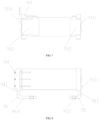
FIG 1 is a schematic view of the structure of Embodiment 1 for magnetic circuit positioning of the present invention. -
FIG. 2 is a cross-sectional view taken along line A-A ofFIG. 1 . -
FIG. 3 is a cross-sectional view taken along line B-B ofFIG. 1 . -
FIG. 4 is a cross-sectional view taken along line C-C ofFIG. 1 . -
FIG. 5 is a cross-sectional view taken along line D-D ofFIG. 1 . -
FIG. 6 is a schematic view of the structure of the magnetic circuit portion (without an armature) of Embodiment 1 for magnetic circuit positioning of the present invention. -
FIG. 7 is a front view of the structure of the magnetic circuit portion (without an armature) of Embodiment 1 for magnetic circuit positioning of the present invention. -
FIG. 8 is a bottom view of the structure of the magnetic circuit portion (without an armature) of Embodiment 1 for magnetic circuit positioning of the present invention. -
FIG. 9 is an exploded view of the structure of the magnetic circuit portion (without an armature) of Embodiment 1 for magnetic circuit positioning of the present invention. -
FIG. 10 is a schematic view of the structure of the base of Embodiment 1 for magnetic circuit positioning of the present invention. -
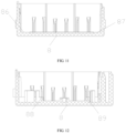
FIG. 11 is a cross-sectional view taken along line E-E ofFIG. 10 . -
FIG. 12 is a cross-sectional view taken along line F-F ofFIG. 10 . -
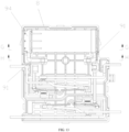
FIG. 13 is a schematic view of the structure of Embodiment 2 for magnetic circuit positioning of the present invention. -
FIG. 14 is a cross-sectional view taken along line G-G ofFIG. 13 . -
FIG. 15 is a cross-sectional view taken along line H-H ofFIG. 13 . -
FIG. 16 is a schematic view of the structure of the magnetic circuit portion (without an armature) of Embodiment 2 for magnetic circuit positioning of the present invention. -
FIG. 17 is an exploded view of the structure of the magnetic circuit portion (without an armature) of Embodiment 2 for magnetic circuit positioning of the present invention. -
FIG. 18 is a schematic view of the structure of the base of Embodiment 2 for magnetic circuit positioning of the present invention. -
FIG. 19 is a cross-sectional view taken along line I-I ofFIG. 18 . -
FIG. 20 is a cross-sectional view taken along line J-J ofFIG. 18 . -
FIG. 21 is an exploded view of the structure of the magnetic circuit portion (without an armature) of Embodiment 3 for magnetic circuit positioning of the present invention. - Referring to
FIGS. 1 to 12 , a magnetic latching relay capable of accurately positioning a magnetic circuit of the present embodiment includes a magnetic circuit portion and abase 8. The magnetic circuit portion includes ayoke 91, acore 92, an armature (not shown), and abobbin 94. Theiron core 92 is inserted into a through-hole 941 of thebobbin 94, and theyoke 91 comprises two yokes, and oneside 911 of each of the twoyokes 91 is connected to theiron core 92 respectively at the both ends of the through-hole 941 of the bobbin and. The armature is fitted between theother side 912 of each of the twoyokes 91. The magnetic circuit portion is mounted on thebase 8, with the axis of the through-hole 941 of the bobbin in a horizontal manner. In the present embodiment, in the twoyokes 91, apositioning convex portion 9111 is further provided on the outward face of theside 911 of the yokes. Positioninggrooves 84 are formed in theside walls 83 of thebase 8 corresponding to the ends of the through holes of the bobbin, respectively, to be engaged with the positioningconvex portion 9111 of the yokes to realize the positioning of the magnetic circuit portions on thebase 8 in the horizontal direction perpendicular to the axis of the bobbin throughhole 941. - In this embodiment, the
positioning groove 84 of the side wall of the base has an elongated shape, and the longitudinal direction of thepositioning groove 84 is disposed along the vertical direction. - In this embodiment, the
positioning groove 84 of theside wall 83 of one side of the base is formed by two outwardly protrudingribs 85 of the side wall. - In this embodiment, the positioning groove of the
side wall 83 of the other side base is formed by an inwardly recessed structure of the side wall. - The portion of
positioning groove 84 surrounded by theribs 85 is an end corresponding to the coil head, and the coil is provided with a coil pin at the end. The recessed structure is formed at an end corresponding to the tail of the coil, and the coil has no coil pins at this end. - In the present embodiment, the positioning
convex portion 9111 of the yoke is composed of two cylinders which are arranged in the vertical direction. - When the magnetic circuit portion is mounted on the
base 8, the bottom end faces 942, 943 of the two ends of thebobbin 94 and the bottom end faces 9121, 9122 of theother sides 912 of the two yokes are mounted as mounting faces on the inner surface of thebase 8. A boss for positioning is further disposed among a bottom end surface of both ends of the bobbin, a bottom end surface of each of the other sides of the two yokes, and a corresponding position of the inner surface of the base to realize the positioning of the magnetic circuit portion on thebase 8 in a downward direction in the vertical direction perpendicular to the axis of the bobbin through hole. - In this embodiment, the positioning bosses are respectively protruded upward along the inner surface of the base at positions corresponding to the bottom end faces of two ends of the bobbin and the bottom end faces of the other sides of the two yokes. That is, the inner surface of the
base 8 is provided with apositioning boss 86 at a mounting portion corresponding to thebottom end surface 942 of the head of thebobbin 94, and the inner surface of thebase 8 is provided with apositioning boss 87 at a mounting portion corresponding to thebottom end surface 943 of the tail of thebobbin 94. Thebottom end surface 9121 of the inner surface of thebase 8 corresponding to theother side 912 of one yoke is provided with apositioning boss 88, and thebottom end surface 9122 of the inner surface of thebase 8 corresponding to theother side 912 of the other yoke is provided with apositioning boss 89. Since thebobbin 94, the mounting surface of theyoke 91, and the mounting surface of thebase 8 are mounted by small-surface contact, the verticality after assembly can be improved. - In the art, a magnetically permeable member that passes a through hole of a bobbin is generally referred to as an iron core, a magnetically permeable member disposed outside the through hole of the bobbin is referred to as a yoke, and a movable magnetically permeable member is referred to as an armature. The magnetic core, the yoke and the armature constitute a magnetic circuit, and the iron core and the yoke can be separate components, such as the structure described in this embodiment, that is, a straight-shaped iron core and two L-shaped yokes, i.e., three components in total. The iron core and the yoke may also be integrally connected; for example, the iron core and one of the yokes are integrally formed, a U-shaped structure is formed by bending, and the other yoke is still L-shaped, i.e., two components in total. For another example, the iron core and the two yokes are integrated into one body, and an integral part of a C-shaped structure is formed by bending, thus the structure is one-piece. For example, two iron cores are stacked in the through hole of the bobbin, and the two iron cores are respectively integrated with the two yokes, so that two U-shaped structures can be formed by bending, and each side of the two U-shaped structures is inserted into the through hole of the bobbin to form a stacked core, i.e., two components in total.
- In the magnetic latching relay capable of accurately positioning the magnetic circuit of the embodiment, two
yokes 91 are used. A positioningconvex portion 9111 is disposed on an outwardly face of oneside 911 of theyoke 91; in theside wall 83 of thebase 8 corresponding to two ends of the throughhole 941 of the bobbin, apositioning groove 84 is provided which can cooperate with the positioningconvex portion 9111 of the yoke, thereby, realizing the positioning of the magnetic circuit portion on thebase 8 in a horizontal direction perpendicular to the axis of the bobbin throughhole 941. In this embodiment, a boss for positioning (that is, the inside of the base 8) is disposed among the bottom end faces of the two ends of the bobbin, the bottom end faces of the other sides of the two yokes, and the corresponding positions of the inner surfaces of the bases, (thebottom end face 942 of the inner surface of thebase 8 corresponding to the head portion of thebobbin 94 is provided with apositioning boss 86, thebottom end face 943 of the inner surface of thebase 8 corresponding to the tail portion of thebobbin 94 is provided with apositioning boss 87, thebottom end face 9121 of the inner surface of thebase 8 corresponding to theother side 912 of one yoke is provided with apositioning boss 88, and thebottom end face 9122 of the inner surface of thebase 8 corresponding to theother side 912 of the other yoke is provided with a positioning boss 89). The positioning of the magnetic circuit portion on the base in a downward direction in the vertical direction perpendicular to the axis of the coil frame through-hole can be achieved. The structure of the embodiment can ensure that the assembly accuracy of the perpendicularity of the magnetic circuit portion is not affected by the flatness of the bottom surface of the base after the base is installed, and the perpendicularity of the magnetic circuit portion after assembling can be within 0.05 mm. Moreover, there is no need for other auxiliary positioning technologies such as dispensing, which eliminates the disadvantages that using a glue bond easily contaminates the working portion of the magnetic circuit portion, thus the production efficiency is greatly improved. - Referring to
FIG. 13 to FIG. 21 , a magnetic latching relay capable of accurately positioning a magnetic circuit of the present embodiment differs from Embodiment 1 in that the positioning boss is disposed at the bobbin and the yoke, and the positioning bosses are respectively formed to protrude downward along the bottom end faces of two ends of thebobbin 94 and the bottom end faces of theother sides 912 of the twoyokes 91. Four positioning bosses are disposed, wherein thepositioning boss 944 is disposed at thebottom end face 942 of the head of thebobbin 94, thepositioning boss 945 is disposed at thebottom end face 943 of the tail of thebobbin 94, thepositioning boss 913 is disposed at thebottom end face 9121 of theother side 912 of one yoke, and thepositioning boss 914 is disposed at the bottom end face 9222 of theother side 912 of the other yoke. - Referring to
FIG. 21 , a magnetic latching relay capable of accurately positioning a magnetic circuit of the present embodiment differs from the Embodiment 2 in that the positioningconvex portion 9111 of theyoke 91 is composed of a rectangular parallelepiped, the length direction of which is along the vertical direction. - In the above embodiment for magnetic circuit positioning, since at least one yoke of the two yokes is provided with a positioning convex portion on the outward side of one side of the yoke, at least one side wall of the side walls of two ends of the base corresponding to the through hole of the bobbin is provided with a positioning groove that can cooperate with the positioning convex portion of the yoke. Thus, positioning of the magnetic circuit portion on the base in a horizontal direction perpendicular to the axis of the through hole of the coil bobbin is achieved. The embodiment of the invention also adopts a boss for positioning among the bottom end faces of the two ends of the bobbin, the bottom end faces of the other sides of the two yokes, and the corresponding positions of the inner surfaces of the bases to realize the magnetic circuit portion being positioned on the base in the downward direction of the vertical direction perpendicular to the axis of the through hole of the coil frame. Therefore, it can be ensured that the assembly accuracy of the verticality of the magnetic circuit portion after being mounted in the base is not affected by the flatness of the bottom surface of the base, and the perpendicularity of the magnetic circuit portion after assembly can be within 0.05 mm. Other auxiliary positioning technologies such as dispensing are not required. The disadvantages of using a glue bond to easily contaminate the working portion of the magnetic circuit portion are eliminated, which greatly improves the production efficiency.
Claims (9)
- A magnetic latching relay capable of accurately positioning a magnetic circuit, comprising a magnetic circuit portion and a base (8), the magnetic circuit portion comprising a yoke (91), an iron core (92), an armature, and a bobbin (94), whereinthe iron core (92) is inserted into a through-hole (941)of the bobbin(94), and the yoke(91) comprises two yokes, and one side(911) of each of the two yokes (91) is connected to the iron core(92) respectively at the both ends of the through-hole(941) of the bobbin(94), and the armature is fitted between the other side(912) of each of the two yokes(91), the magnetic circuit portion is mounted on the base(8), with the axis of the through-hole(941) of the bobbin(94) in a horizontal manner;in at least one of the two yokes(91), a positioning convex portion(9111) is further provided on the outward face of the side(911) of the yoke(91), the magnetic latching relay being characterised in that positioning grooves(84) are formed in at least one side wall(83) to be engaged with the positioning convex portion (911 1)of the yoke, to realize the positioning of the magnetic circuit portions on the base(8) in the horizontal direction perpendicular to the axis of the bobbin through hole (941).
- The magnetic latching relay capable of accurately positioning a magnetic circuit according to claim 1, wherein the positioning groove(84) of the side wall(83) of the base(8) has an elongated shape, and the longitudinal direction of the positioning groove(84) is disposed along the vertical direction.
- The magnetic latching relay capable of accurately positioning a magnetic circuit according to claim 2, wherein the positioning groove (84) of the side wall (83) of the base (8) is formed by two ribs(85) of the side wall which are outwardly protruding and along the vertical direction.
- The magnetic latching relay capable of accurately positioning a magnetic circuit according to claim 2, wherein the positioning groove (84) of the side wall (83) of the base (8) is formed by an inwardly recessed structure of the side wall.
- The magnetic latching relay capable of accurately positioning a magnetic circuit according to claim 2, wherein the positioning convex portion (9111) of the yoke (91) is composed of two cylinders which are arranged in the vertical direction.
- The magnetic latching relay capable of accurately positioning a magnetic circuit according to claim 2, wherein the positioning convex portion (9111) of the yoke (91) is composed of a rectangular parallelepiped, the length direction of which is along the vertical direction.
- The magnetic latching relay capable of accurately positioning a magnetic circuit according to claim 1, wherein when the magnetic circuit portion is mounted on the base(8), the bottom end faces (942,943) of the two ends of the bobbin (94) and the bottom end faces (9121,9122) of the other sides (912) of the two yokes(91) are mounted as mounting faces on the inner surface of the base(8), a boss for positioning is further disposed among a bottom end surface of both ends of the bobbin, a bottom end surface of each of the other sides of the two yokes, and a corresponding position of the inner surface of the base to realize the positioning of the magnetic circuit portion on the base(8) in a downward direction in the vertical direction perpendicular to the axis of the bobbin through hole.
- The magnetic latching relay capable of accurately positioning a magnetic circuit according to claim 7, wherein the positioning bosses (86, 87,88,89) are respectively formed to protrude downward along the bottom end faces (942,943) of two ends of the bobbin (94) and the bottom end faces (9121,9122) of the other sides (912) of the two yokes (91).
- The magnetic latching relay capable of accurately positioning a magnetic circuit according to claim 7, wherein the positioning bosses(86,87,88,89) are respectively protruded upward along the inner surface of the base(8) at positions corresponding to the bottom end faces (942,943) of two ends of the bobbin(94) and the bottom end faces(9121,9122) of the other sides(912) of the two yokes(91).
Applications Claiming Priority (5)
| Application Number | Priority Date | Filing Date | Title |
|---|---|---|---|
| CN201611051896.1A CN106504947B (en) | 2016-11-25 | 2016-11-25 | A kind of contact portion assembles the magnetic latching relay of anti-scrapings and accurate positioning |
| CN201611051945.1A CN106504949A (en) | 2016-11-25 | 2016-11-25 | A kind of magnetic latching relay that can resist short circuit current flow |
| CN201611189010.XA CN106504951B (en) | 2016-11-25 | 2016-12-21 | One kind can be realized the pinpoint magnetic latching relay of magnetic circuit |
| EP17874084.1A EP3547344B1 (en) | 2016-11-25 | 2017-11-24 | Magnetic latching relay capable of resisting short-circuit current |
| PCT/CN2017/112949 WO2018095419A1 (en) | 2016-11-25 | 2017-11-24 | Magnetic latching relay capable of resisting short-circuit current |
Related Parent Applications (2)
| Application Number | Title | Priority Date | Filing Date |
|---|---|---|---|
| EP17874084.1A Division EP3547344B1 (en) | 2016-11-25 | 2017-11-24 | Magnetic latching relay capable of resisting short-circuit current |
| EP17874084.1A Division-Into EP3547344B1 (en) | 2016-11-25 | 2017-11-24 | Magnetic latching relay capable of resisting short-circuit current |
Publications (2)
| Publication Number | Publication Date |
|---|---|
| EP3965135A1 EP3965135A1 (en) | 2022-03-09 |
| EP3965135B1 true EP3965135B1 (en) | 2023-04-12 |
Family
ID=62195750
Family Applications (2)
| Application Number | Title | Priority Date | Filing Date |
|---|---|---|---|
| EP17874084.1A Active EP3547344B1 (en) | 2016-11-25 | 2017-11-24 | Magnetic latching relay capable of resisting short-circuit current |
| EP21193270.2A Active EP3965135B1 (en) | 2016-11-25 | 2017-11-24 | Magnetic latching relay capable of accurately positioning magnetic circuit |
Family Applications Before (1)
| Application Number | Title | Priority Date | Filing Date |
|---|---|---|---|
| EP17874084.1A Active EP3547344B1 (en) | 2016-11-25 | 2017-11-24 | Magnetic latching relay capable of resisting short-circuit current |
Country Status (5)
| Country | Link |
|---|---|
| US (2) | US11031202B2 (en) |
| EP (2) | EP3547344B1 (en) |
| ES (2) | ES2949563T3 (en) |
| PL (2) | PL3965135T3 (en) |
| WO (1) | WO2018095419A1 (en) |
Families Citing this family (10)
| Publication number | Priority date | Publication date | Assignee | Title |
|---|---|---|---|---|
| PL3965135T3 (en) | 2016-11-25 | 2023-09-18 | Xiamen Hongfa Electric Power Controls Co., Ltd. | Magnetic latching relay capable of accurately positioning magnetic circuit |
| DE102019117804B4 (en) * | 2019-07-02 | 2021-08-12 | Johnson Electric Germany GmbH & Co. KG | Switching device with an electrical contact system |
| CN110610834B (en) * | 2019-10-15 | 2025-01-28 | 厦门宏发电力电器有限公司 | A magnetic latching relay with micro switch |
| CN111725032B (en) * | 2020-05-13 | 2025-10-03 | 厦门宏发电声股份有限公司 | A snap-on electromagnetic relay with a horizontal magnetic circuit structure |
| WO2022127627A1 (en) * | 2020-12-15 | 2022-06-23 | 厦门宏发电力电器有限公司 | Relay movable spring capable of reducing temperature rise and relay |
| CN112786349A (en) * | 2021-02-01 | 2021-05-11 | 昆山国力电子科技股份有限公司 | Anti-short circuit type vacuum relay |
| US20240282539A1 (en) * | 2021-06-18 | 2024-08-22 | Xiamen Hongfa Electric Power Controls Co., Ltd. | Multi-phase electromagnetic relay |
| CN117558585A (en) * | 2022-08-03 | 2024-02-13 | 厦门宏发电力电器有限公司 | a relay |
| TWI811135B (en) * | 2022-10-14 | 2023-08-01 | 百容電子股份有限公司 | Electromagnetic relay |
| CN119008327A (en) * | 2023-05-18 | 2024-11-22 | 厦门宏发电力电器有限公司 | Relay device |
Family Cites Families (32)
| Publication number | Priority date | Publication date | Assignee | Title |
|---|---|---|---|---|
| JPS4873771U (en) * | 1971-12-17 | 1973-09-13 | ||
| JPS5816425A (en) * | 1981-07-20 | 1983-01-31 | 和泉電気株式会社 | Iminature relay |
| JP3646408B2 (en) | 1996-06-14 | 2005-05-11 | オムロン株式会社 | Electromagnetic relay |
| EP1756845B1 (en) | 2004-04-30 | 2013-11-13 | Johnson Electric International (UK) Limited | Electrical contactor |
| CN101231923B (en) * | 2007-02-05 | 2010-11-24 | 厦门宏发电力电器有限公司 | Electromagnetic relay resisting electrodynamic repulsion |
| CN201063318Y (en) | 2007-03-20 | 2008-05-21 | 浙江中孚电子有限公司 | External relay remaining by magnetism |
| CN201112284Y (en) | 2007-06-19 | 2008-09-10 | 吴卫明 | Magnetic retaining relay |
| CN201112290Y (en) | 2007-08-28 | 2008-09-10 | 上海贝斯特电器制造有限公司 | Magnetic retaining relay |
| CN201435353Y (en) | 2009-06-22 | 2010-03-31 | 厦门宏发电力电器有限公司 | Magnetic latching relay of rotary magnetic circuit structure |
| CN201522973U (en) | 2009-08-14 | 2010-07-07 | 郁晓亮 | Double-layer three-phase magnetic latching relay |
| CN201754389U (en) * | 2010-08-17 | 2011-03-02 | 东莞市三友联众电器有限公司 | Magnetic latching relay |
| CN202394819U (en) | 2012-01-11 | 2012-08-22 | 浙江格蕾特电器有限公司 | Magnetic latching relay |
| CN202585269U (en) | 2012-04-09 | 2012-12-05 | 安徽省明光市爱福电子有限公司 | Yoke iron and base mounting structure |
| CN202996731U (en) | 2012-12-28 | 2013-06-12 | 厦门宏发电力电器有限公司 | Magnetic latching relay with stagger cooperation between push block and movable spring |
| EP2806441B1 (en) | 2013-05-24 | 2017-07-12 | Tyco Electronics Austria GmbH | Electric switching device with enhanced Lorentz force bias |
| CN203415504U (en) | 2013-06-14 | 2014-01-29 | 东莞市三友联众电器有限公司 | A relay contact system |
| CN203562369U (en) | 2013-12-05 | 2014-04-23 | 德力西电气有限公司 | Contact plate fixing structure |
| JP5700110B1 (en) * | 2013-12-27 | 2015-04-15 | オムロン株式会社 | Contact terminal assembly structure and electromagnetic relay equipped with the same |
| CN103794415B (en) * | 2014-01-23 | 2017-04-05 | 厦门宏发电力电器有限公司 | Electromagnetic relay and movable contact spring thereof |
| CN203721645U (en) | 2014-01-23 | 2014-07-16 | 厦门宏发电力电器有限公司 | Electromagnetic relay and electromagnetic assembly thereof |
| CN104362044B (en) | 2014-10-28 | 2017-01-18 | 浙江正泰电器股份有限公司 | Relay capable of preventing large-current contact separation |
| CN204242959U (en) | 2014-12-11 | 2015-04-01 | 浙江康信汽车电器有限公司 | firm type relay |
| CN104752102B (en) | 2015-02-06 | 2017-09-05 | 厦门宏发电力电器有限公司 | The magnetic latching relay and its assembly method of a kind of double fixed mount magnetic structures of band |
| CN204651252U (en) | 2015-04-15 | 2015-09-16 | 浙江正泰电器股份有限公司 | The mounting structure of relay radome |
| CN205211668U (en) | 2015-12-03 | 2016-05-04 | 厦门宏发电力电器有限公司 | Quiet spring part and magnetic latching relay with effect of buffering kinetic energy |
| CN105590795B (en) | 2015-12-03 | 2018-02-13 | 厦门宏发电力电器有限公司 | A kind of location structure of the magnetic circuit part of magnetic latching relay |
| CN106024526B (en) * | 2016-06-20 | 2018-05-22 | 惠州亿纬控股有限公司 | A kind of clapper-type electromagnetic relay for high voltage direct current |
| CN206340490U (en) | 2016-11-25 | 2017-07-18 | 厦门宏发电力电器有限公司 | Contact portion assembles the magnetic latching relay of anti-scrapings and accurate positioning |
| CN106504949A (en) | 2016-11-25 | 2017-03-15 | 厦门宏发电力电器有限公司 | A kind of magnetic latching relay that can resist short circuit current flow |
| PL3965135T3 (en) | 2016-11-25 | 2023-09-18 | Xiamen Hongfa Electric Power Controls Co., Ltd. | Magnetic latching relay capable of accurately positioning magnetic circuit |
| CN106504951B (en) | 2016-11-25 | 2019-02-19 | 厦门宏发电力电器有限公司 | One kind can be realized the pinpoint magnetic latching relay of magnetic circuit |
| CN206322647U (en) * | 2016-11-25 | 2017-07-11 | 厦门宏发电力电器有限公司 | The magnetic latching relay of short circuit current flow can be resisted |
-
2017
- 2017-11-24 PL PL21193270.2T patent/PL3965135T3/en unknown
- 2017-11-24 ES ES21193270T patent/ES2949563T3/en active Active
- 2017-11-24 PL PL17874084T patent/PL3547344T3/en unknown
- 2017-11-24 WO PCT/CN2017/112949 patent/WO2018095419A1/en not_active Ceased
- 2017-11-24 US US16/464,254 patent/US11031202B2/en active Active
- 2017-11-24 EP EP17874084.1A patent/EP3547344B1/en active Active
- 2017-11-24 EP EP21193270.2A patent/EP3965135B1/en active Active
- 2017-11-24 ES ES17874084T patent/ES2903234T3/en active Active
-
2021
- 2021-05-07 US US17/314,811 patent/US11476070B2/en active Active
Also Published As
| Publication number | Publication date |
|---|---|
| US11476070B2 (en) | 2022-10-18 |
| US20190287749A1 (en) | 2019-09-19 |
| EP3547344A1 (en) | 2019-10-02 |
| EP3965135A1 (en) | 2022-03-09 |
| WO2018095419A1 (en) | 2018-05-31 |
| US20210265123A1 (en) | 2021-08-26 |
| EP3547344A4 (en) | 2020-09-16 |
| ES2903234T3 (en) | 2022-03-31 |
| PL3965135T3 (en) | 2023-09-18 |
| EP3547344B1 (en) | 2021-11-10 |
| PL3547344T3 (en) | 2022-03-07 |
| ES2949563T3 (en) | 2023-09-29 |
| US11031202B2 (en) | 2021-06-08 |
Similar Documents
| Publication | Publication Date | Title |
|---|---|---|
| US11476070B2 (en) | Magnetic latching relay capable of accurately positioning magnetic circuit | |
| EP3608938B1 (en) | Magnetic latching relay capable of resisting short-circuit current | |
| KR102725406B1 (en) | Direct-current relay resistant to short-circuit current | |
| CN204651253U (en) | Magnetic latching relay | |
| EP2717287A1 (en) | Electromagnetic relay | |
| CN204668248U (en) | The contact system of magnetic latching relay | |
| JP2023046405A (en) | High voltage direct current relay with auxiliary contact | |
| US20250014851A1 (en) | Switching device with a stopper and method for operating a switching device | |
| US11114264B2 (en) | Insertion structure between static spring and bobbin | |
| EP4143867B1 (en) | High-voltage dc relay | |
| CN205984822U (en) | Small -size high -power electromagnetic relay | |
| CN104538256A (en) | Alternating current contactor | |
| CN204303691U (en) | A kind of A.C. contactor | |
| CN102891050B (en) | Socket type ground fault circuit interrupter | |
| CN219917049U (en) | Delay release and circuit breaker | |
| CN206524284U (en) | Miniature electro-magnetic relay | |
| CN215869153U (en) | Direct-acting magnetic circuit part and high-voltage direct-current relay | |
| CN220253152U (en) | Electromagnetic leakage circuit breaker | |
| CN222126412U (en) | Small-sized circuit breaker | |
| CN110400729B (en) | A small circuit breaker | |
| CN223193713U (en) | Relay with insulation and voltage resistance and convenient assembly | |
| CN218385091U (en) | Single-frame low-voltage frame circuit breaker | |
| CN222939822U (en) | Electromagnetic relay | |
| CN216354047U (en) | Circuit breaker | |
| CN222530333U (en) | Push rod type high withstand voltage relay |
Legal Events
| Date | Code | Title | Description |
|---|---|---|---|
| PUAI | Public reference made under article 153(3) epc to a published international application that has entered the european phase |
Free format text: ORIGINAL CODE: 0009012 |
|
| STAA | Information on the status of an ep patent application or granted ep patent |
Free format text: STATUS: REQUEST FOR EXAMINATION WAS MADE |
|
| 17P | Request for examination filed |
Effective date: 20210826 |
|
| AC | Divisional application: reference to earlier application |
Ref document number: 3547344 Country of ref document: EP Kind code of ref document: P |
|
| AK | Designated contracting states |
Kind code of ref document: A1 Designated state(s): AL AT BE BG CH CY CZ DE DK EE ES FI FR GB GR HR HU IE IS IT LI LT LU LV MC MK MT NL NO PL PT RO RS SE SI SK SM TR |
|
| GRAP | Despatch of communication of intention to grant a patent |
Free format text: ORIGINAL CODE: EPIDOSNIGR1 |
|
| STAA | Information on the status of an ep patent application or granted ep patent |
Free format text: STATUS: GRANT OF PATENT IS INTENDED |
|
| INTG | Intention to grant announced |
Effective date: 20221024 |
|
| GRAS | Grant fee paid |
Free format text: ORIGINAL CODE: EPIDOSNIGR3 |
|
| GRAA | (expected) grant |
Free format text: ORIGINAL CODE: 0009210 |
|
| STAA | Information on the status of an ep patent application or granted ep patent |
Free format text: STATUS: THE PATENT HAS BEEN GRANTED |
|
| AC | Divisional application: reference to earlier application |
Ref document number: 3547344 Country of ref document: EP Kind code of ref document: P |
|
| AK | Designated contracting states |
Kind code of ref document: B1 Designated state(s): AL AT BE BG CH CY CZ DE DK EE ES FI FR GB GR HR HU IE IS IT LI LT LU LV MC MK MT NL NO PL PT RO RS SE SI SK SM TR |
|
| REG | Reference to a national code |
Ref country code: GB Ref legal event code: FG4D |
|
| REG | Reference to a national code |
Ref country code: CH Ref legal event code: EP |
|
| REG | Reference to a national code |
Ref country code: DE Ref legal event code: R096 Ref document number: 602017067773 Country of ref document: DE |
|
| REG | Reference to a national code |
Ref country code: IE Ref legal event code: FG4D |
|
| REG | Reference to a national code |
Ref country code: AT Ref legal event code: REF Ref document number: 1560252 Country of ref document: AT Kind code of ref document: T Effective date: 20230515 |
|
| P01 | Opt-out of the competence of the unified patent court (upc) registered |
Effective date: 20230523 |
|
| REG | Reference to a national code |
Ref country code: NL Ref legal event code: FP |
|
| REG | Reference to a national code |
Ref country code: LT Ref legal event code: MG9D |
|
| REG | Reference to a national code |
Ref country code: ES Ref legal event code: FG2A Ref document number: 2949563 Country of ref document: ES Kind code of ref document: T3 Effective date: 20230929 |
|
| PG25 | Lapsed in a contracting state [announced via postgrant information from national office to epo] |
Ref country code: SE Free format text: LAPSE BECAUSE OF FAILURE TO SUBMIT A TRANSLATION OF THE DESCRIPTION OR TO PAY THE FEE WITHIN THE PRESCRIBED TIME-LIMIT Effective date: 20230412 Ref country code: PT Free format text: LAPSE BECAUSE OF FAILURE TO SUBMIT A TRANSLATION OF THE DESCRIPTION OR TO PAY THE FEE WITHIN THE PRESCRIBED TIME-LIMIT Effective date: 20230814 Ref country code: NO Free format text: LAPSE BECAUSE OF FAILURE TO SUBMIT A TRANSLATION OF THE DESCRIPTION OR TO PAY THE FEE WITHIN THE PRESCRIBED TIME-LIMIT Effective date: 20230712 |
|
| PG25 | Lapsed in a contracting state [announced via postgrant information from national office to epo] |
Ref country code: RS Free format text: LAPSE BECAUSE OF FAILURE TO SUBMIT A TRANSLATION OF THE DESCRIPTION OR TO PAY THE FEE WITHIN THE PRESCRIBED TIME-LIMIT Effective date: 20230412 Ref country code: LV Free format text: LAPSE BECAUSE OF FAILURE TO SUBMIT A TRANSLATION OF THE DESCRIPTION OR TO PAY THE FEE WITHIN THE PRESCRIBED TIME-LIMIT Effective date: 20230412 Ref country code: LT Free format text: LAPSE BECAUSE OF FAILURE TO SUBMIT A TRANSLATION OF THE DESCRIPTION OR TO PAY THE FEE WITHIN THE PRESCRIBED TIME-LIMIT Effective date: 20230412 Ref country code: IS Free format text: LAPSE BECAUSE OF FAILURE TO SUBMIT A TRANSLATION OF THE DESCRIPTION OR TO PAY THE FEE WITHIN THE PRESCRIBED TIME-LIMIT Effective date: 20230812 Ref country code: HR Free format text: LAPSE BECAUSE OF FAILURE TO SUBMIT A TRANSLATION OF THE DESCRIPTION OR TO PAY THE FEE WITHIN THE PRESCRIBED TIME-LIMIT Effective date: 20230412 Ref country code: GR Free format text: LAPSE BECAUSE OF FAILURE TO SUBMIT A TRANSLATION OF THE DESCRIPTION OR TO PAY THE FEE WITHIN THE PRESCRIBED TIME-LIMIT Effective date: 20230713 |
|
| PG25 | Lapsed in a contracting state [announced via postgrant information from national office to epo] |
Ref country code: FI Free format text: LAPSE BECAUSE OF FAILURE TO SUBMIT A TRANSLATION OF THE DESCRIPTION OR TO PAY THE FEE WITHIN THE PRESCRIBED TIME-LIMIT Effective date: 20230412 |
|
| REG | Reference to a national code |
Ref country code: DE Ref legal event code: R097 Ref document number: 602017067773 Country of ref document: DE |
|
| PG25 | Lapsed in a contracting state [announced via postgrant information from national office to epo] |
Ref country code: SK Free format text: LAPSE BECAUSE OF FAILURE TO SUBMIT A TRANSLATION OF THE DESCRIPTION OR TO PAY THE FEE WITHIN THE PRESCRIBED TIME-LIMIT Effective date: 20230412 |
|
| PG25 | Lapsed in a contracting state [announced via postgrant information from national office to epo] |
Ref country code: SM Free format text: LAPSE BECAUSE OF FAILURE TO SUBMIT A TRANSLATION OF THE DESCRIPTION OR TO PAY THE FEE WITHIN THE PRESCRIBED TIME-LIMIT Effective date: 20230412 Ref country code: SK Free format text: LAPSE BECAUSE OF FAILURE TO SUBMIT A TRANSLATION OF THE DESCRIPTION OR TO PAY THE FEE WITHIN THE PRESCRIBED TIME-LIMIT Effective date: 20230412 Ref country code: RO Free format text: LAPSE BECAUSE OF FAILURE TO SUBMIT A TRANSLATION OF THE DESCRIPTION OR TO PAY THE FEE WITHIN THE PRESCRIBED TIME-LIMIT Effective date: 20230412 Ref country code: EE Free format text: LAPSE BECAUSE OF FAILURE TO SUBMIT A TRANSLATION OF THE DESCRIPTION OR TO PAY THE FEE WITHIN THE PRESCRIBED TIME-LIMIT Effective date: 20230412 Ref country code: DK Free format text: LAPSE BECAUSE OF FAILURE TO SUBMIT A TRANSLATION OF THE DESCRIPTION OR TO PAY THE FEE WITHIN THE PRESCRIBED TIME-LIMIT Effective date: 20230412 Ref country code: CZ Free format text: LAPSE BECAUSE OF FAILURE TO SUBMIT A TRANSLATION OF THE DESCRIPTION OR TO PAY THE FEE WITHIN THE PRESCRIBED TIME-LIMIT Effective date: 20230412 |
|
| REG | Reference to a national code |
Ref country code: AT Ref legal event code: UEP Ref document number: 1560252 Country of ref document: AT Kind code of ref document: T Effective date: 20230412 |
|
| PLBE | No opposition filed within time limit |
Free format text: ORIGINAL CODE: 0009261 |
|
| STAA | Information on the status of an ep patent application or granted ep patent |
Free format text: STATUS: NO OPPOSITION FILED WITHIN TIME LIMIT |
|
| 26N | No opposition filed |
Effective date: 20240115 |
|
| PG25 | Lapsed in a contracting state [announced via postgrant information from national office to epo] |
Ref country code: SI Free format text: LAPSE BECAUSE OF FAILURE TO SUBMIT A TRANSLATION OF THE DESCRIPTION OR TO PAY THE FEE WITHIN THE PRESCRIBED TIME-LIMIT Effective date: 20230412 |
|
| PG25 | Lapsed in a contracting state [announced via postgrant information from national office to epo] |
Ref country code: SI Free format text: LAPSE BECAUSE OF FAILURE TO SUBMIT A TRANSLATION OF THE DESCRIPTION OR TO PAY THE FEE WITHIN THE PRESCRIBED TIME-LIMIT Effective date: 20230412 |
|
| REG | Reference to a national code |
Ref country code: CH Ref legal event code: PL |
|
| PG25 | Lapsed in a contracting state [announced via postgrant information from national office to epo] |
Ref country code: MC Free format text: LAPSE BECAUSE OF FAILURE TO SUBMIT A TRANSLATION OF THE DESCRIPTION OR TO PAY THE FEE WITHIN THE PRESCRIBED TIME-LIMIT Effective date: 20230412 |
|
| PG25 | Lapsed in a contracting state [announced via postgrant information from national office to epo] |
Ref country code: LU Free format text: LAPSE BECAUSE OF NON-PAYMENT OF DUE FEES Effective date: 20231124 |
|
| PG25 | Lapsed in a contracting state [announced via postgrant information from national office to epo] |
Ref country code: CH Free format text: LAPSE BECAUSE OF NON-PAYMENT OF DUE FEES Effective date: 20231130 |
|
| PG25 | Lapsed in a contracting state [announced via postgrant information from national office to epo] |
Ref country code: MC Free format text: LAPSE BECAUSE OF FAILURE TO SUBMIT A TRANSLATION OF THE DESCRIPTION OR TO PAY THE FEE WITHIN THE PRESCRIBED TIME-LIMIT Effective date: 20230412 Ref country code: LU Free format text: LAPSE BECAUSE OF NON-PAYMENT OF DUE FEES Effective date: 20231124 Ref country code: CH Free format text: LAPSE BECAUSE OF NON-PAYMENT OF DUE FEES Effective date: 20231130 |
|
| REG | Reference to a national code |
Ref country code: BE Ref legal event code: MM Effective date: 20231130 |
|
| REG | Reference to a national code |
Ref country code: IE Ref legal event code: MM4A |
|
| PG25 | Lapsed in a contracting state [announced via postgrant information from national office to epo] |
Ref country code: IE Free format text: LAPSE BECAUSE OF NON-PAYMENT OF DUE FEES Effective date: 20231124 |
|
| PG25 | Lapsed in a contracting state [announced via postgrant information from national office to epo] |
Ref country code: BE Free format text: LAPSE BECAUSE OF NON-PAYMENT OF DUE FEES Effective date: 20231130 |
|
| PG25 | Lapsed in a contracting state [announced via postgrant information from national office to epo] |
Ref country code: IE Free format text: LAPSE BECAUSE OF NON-PAYMENT OF DUE FEES Effective date: 20231124 Ref country code: BE Free format text: LAPSE BECAUSE OF NON-PAYMENT OF DUE FEES Effective date: 20231130 |
|
| PG25 | Lapsed in a contracting state [announced via postgrant information from national office to epo] |
Ref country code: BG Free format text: LAPSE BECAUSE OF FAILURE TO SUBMIT A TRANSLATION OF THE DESCRIPTION OR TO PAY THE FEE WITHIN THE PRESCRIBED TIME-LIMIT Effective date: 20230412 |
|
| PG25 | Lapsed in a contracting state [announced via postgrant information from national office to epo] |
Ref country code: BG Free format text: LAPSE BECAUSE OF FAILURE TO SUBMIT A TRANSLATION OF THE DESCRIPTION OR TO PAY THE FEE WITHIN THE PRESCRIBED TIME-LIMIT Effective date: 20230412 |
|
| PG25 | Lapsed in a contracting state [announced via postgrant information from national office to epo] |
Ref country code: CY Free format text: LAPSE BECAUSE OF FAILURE TO SUBMIT A TRANSLATION OF THE DESCRIPTION OR TO PAY THE FEE WITHIN THE PRESCRIBED TIME-LIMIT; INVALID AB INITIO Effective date: 20171124 |
|
| PG25 | Lapsed in a contracting state [announced via postgrant information from national office to epo] |
Ref country code: HU Free format text: LAPSE BECAUSE OF FAILURE TO SUBMIT A TRANSLATION OF THE DESCRIPTION OR TO PAY THE FEE WITHIN THE PRESCRIBED TIME-LIMIT; INVALID AB INITIO Effective date: 20171124 |
|
| PG25 | Lapsed in a contracting state [announced via postgrant information from national office to epo] |
Ref country code: TR Free format text: LAPSE BECAUSE OF FAILURE TO SUBMIT A TRANSLATION OF THE DESCRIPTION OR TO PAY THE FEE WITHIN THE PRESCRIBED TIME-LIMIT Effective date: 20230412 |
|
| PGFP | Annual fee paid to national office [announced via postgrant information from national office to epo] |
Ref country code: NL Payment date: 20251119 Year of fee payment: 9 |
|
| PGFP | Annual fee paid to national office [announced via postgrant information from national office to epo] |
Ref country code: DE Payment date: 20251126 Year of fee payment: 9 |
|
| PGFP | Annual fee paid to national office [announced via postgrant information from national office to epo] |
Ref country code: GB Payment date: 20251120 Year of fee payment: 9 |
|
| PGFP | Annual fee paid to national office [announced via postgrant information from national office to epo] |
Ref country code: AT Payment date: 20251117 Year of fee payment: 9 |
|
| PGFP | Annual fee paid to national office [announced via postgrant information from national office to epo] |
Ref country code: IT Payment date: 20251128 Year of fee payment: 9 |
|
| PGFP | Annual fee paid to national office [announced via postgrant information from national office to epo] |
Ref country code: FR Payment date: 20251125 Year of fee payment: 9 |
|
| PGFP | Annual fee paid to national office [announced via postgrant information from national office to epo] |
Ref country code: PL Payment date: 20251114 Year of fee payment: 9 |
|
| PGFP | Annual fee paid to national office [announced via postgrant information from national office to epo] |
Ref country code: ES Payment date: 20251216 Year of fee payment: 9 |