EP3965022A1 - Method for synthesizing product of pauli rotations in a quantum circuit and process for synthesizing quantum circuits for trotter-suzuki n-order expansion - Google Patents
Method for synthesizing product of pauli rotations in a quantum circuit and process for synthesizing quantum circuits for trotter-suzuki n-order expansion Download PDFInfo
- Publication number
- EP3965022A1 EP3965022A1 EP20305969.6A EP20305969A EP3965022A1 EP 3965022 A1 EP3965022 A1 EP 3965022A1 EP 20305969 A EP20305969 A EP 20305969A EP 3965022 A1 EP3965022 A1 EP 3965022A1
- Authority
- EP
- European Patent Office
- Prior art keywords
- rotations
- row
- quantum
- circuit
- pauli
- Prior art date
- Legal status (The legal status is an assumption and is not a legal conclusion. Google has not performed a legal analysis and makes no representation as to the accuracy of the status listed.)
- Pending
Links
Images






Classifications
-
- G—PHYSICS
- G06—COMPUTING OR CALCULATING; COUNTING
- G06N—COMPUTING ARRANGEMENTS BASED ON SPECIFIC COMPUTATIONAL MODELS
- G06N10/00—Quantum computing, i.e. information processing based on quantum-mechanical phenomena
-
- G—PHYSICS
- G06—COMPUTING OR CALCULATING; COUNTING
- G06F—ELECTRIC DIGITAL DATA PROCESSING
- G06F11/00—Error detection; Error correction; Monitoring
- G06F11/30—Monitoring
- G06F11/34—Recording or statistical evaluation of computer activity, e.g. of down time, of input/output operation ; Recording or statistical evaluation of user activity, e.g. usability assessment
- G06F11/3442—Recording or statistical evaluation of computer activity, e.g. of down time, of input/output operation ; Recording or statistical evaluation of user activity, e.g. usability assessment for planning or managing the needed capacity
Definitions
- the invention concerns methods for synthesizing product of Pauli rotations in a quantum circuit and processes for synthesizing quantum circuits for Trotter-Suzuki n-order expansion.
- this method requires an exponential number of steps and time to obtain these results, since it is needed, as a preprocessing step, to first modify the circuit to obtain only rotational quantum gates along Z-axis, which is complex and time consuming.
- the invention at least partially remedies the shortcuts of the prior art and optimizes the synthesizing of quantum circuit comprising Pauli rotations by generalizing the Graysynth algorithm.
- the quantum circuit it will be beneficial to transform the quantum circuit to obtain a table showing clearly the entanglement between the qubits, and the rotation that applies to each qubit, or to be provided with a table corresponding to the quantum circuit.
- the rotations in te quantum circuit will present small angles.
- the method will recursively choose a pivot row on which to apply a reduced number and predetermined types of quantum gates to finally obtain a synthesized quantum circuits independently of the type of rotational quantum gates initially present in the quantum circuit.
- the method according to the invention therefore enables the compiling of a quantum circuit in a way with improved automation and optimization and suitable for any Paul rotations.
- the method according to the invention leads to a synthesized quantum circuit with an optimized CNOT count.
- the table is provided after:
- the method can be applied without having a quantum circuit by only being provided with the table.
- the method can be applied without being provided with the table already written, the table can be obtained from the quantum circuit.
- the method further comprises:
- the method can be applied with the table and/or the rotation circuit.
- the method further comprises:
- the conjugation step further comprises:
- the reversed quantum gates ensure to have the same circuit at the end.
- the method comprises, before determining the pivot row:
- the conjugating step comprises:
- the Clifford quantum gates preferably comprise :
- the method further comprises an optimizing step wherein the returned synthesized rotation circuit is split to obtain:
- the second sub-circuit can be taken into account by modifying the measurements at the end of the method, for example.
- a Clifford correction corresponding to the second sub-circuit is applied to the first sub-circuit.
- the Clifford correction can be calculated by various methods know in the art. The final execution of the circuit is then easier and more optimized.
- the product of Pauli rotations corresponds to a Hamiltonian simulation.
- Figures 1A to 1E illustrates a particular example of a phase polynomial synthesis, performed through Graysynth algorithm.
- Phase polynomials form a particular set of unitary operators that can be implemented using only CNOT and rotation along Z-axis (or RZ gate) gates.
- This product can be described in the form of a phase gadget sequence, using ZX calculus for example, as illustrated in figure 1A .
- Each of these gadget comprise a collection of striped Z nodes attached to a pair of crossed X nodes and nodes carrying the rotation angle ⁇ 1 , ⁇ 2 , ⁇ 3 .
- Each line corresponds to one qubit q0, q1, q2.
- the synthesis starts by inserting a phase gate in place of the last gadget carrying the rotation angle ⁇ 3 since this gadget is trivial and does not require and CNOT gate for its implementation. Indeed, the rotation angle only applies on qubit q2.
- the inserted phase gate can be commuted to the beginning of the phase gadget sequence. The result of this first step is illustrated on figure 1B .
- a pair of CNOT gates is injected in the phase gadget sequence, before the two gadgets carrying the rotations angles ⁇ 1 , ⁇ 2 .
- the quantum gates and the phase gadget can be placed in any order.
- the gadget carrying the rotation angle ⁇ 1 can be replaced with a phase gadget that will lodge itself against the first CNOT gate. Then the last remaining gadget carrying the rotation angle ⁇ 2 is conjugated with a last CNOT gate?.
- the final obtained phase gadget sequence is shown on figure 1E .
- the quantum circuit obtained at the end of the Graysynth algorithm comprises three phase gadgets carrying the rotation angles ⁇ 1 , ⁇ 2 , ⁇ 3 , and four CNOT gates.
- Graysynth algorithm performs the conjugation of the phase gadgets by CNOT gates in order to reduce their arity.
- the algorithm is called recursively until all gadgets are of arity 1, or, in other words, until all the qubits perform only 1-qubit rotation.
- the recursive structure of the Graysynth algorithm can also be illustrated by use of a table depicting the Pauli product.
- the gadgets are represented in a p x m table, where each column represents a parity and each line represents a qubit.
- each column represents a parity
- each line represents a qubit.
- the Paul product described above ⁇ 1 Z 0 Z 1 + ⁇ 2 Z 0 Z 1 Z 2 + ⁇ 3 Z 1
- the Graysynth algorithm determines a pivot row in the table, by looking for the row having the most 0s or 1s among all the remaining columns.
- the 1s represent the Z rotations and the 0s represent the identities.
- the algorithm is then called recursively in two successive steps.
- the algorithm is called recursively on the columns containing 0s on the pivot row while removing the pivot row from the possible interacting rows.
- the algorithm is called recursively on the columns containing 1s on the pivot row while looking for a target row that shares the largest possible number of 1s with the pivot row among the remaining interacting rows
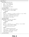
- figure 2 illustrates the pseudo code of Graysynth algorithm.
- Figure 3 illustrates the step of the method according to an embodiment.
- the Pauli product is rewritten with a table of p x m dimension, with p the number of qubits, m the number of rotations, and a list of corresponding angles ⁇ of length m .
- the table is provided and there is no step of re-writing the Hamiltonian product (or "Hamiltonian"). This step corresponds to step S1 of figure 3 .
- Graysynth algorithm allows synthesizing any type of Hamiltonian.
- the above described Hamiltonian comprises arbitrary rotations including X, Y and Z rotations and identities (represented by hyphens in the table).
- Graysynth After determining a pivot row, Graysynth recursively calls the 0s entries in the pivot row, and then the 1s entries in the pivot row.
- CNOT gates are inserted between the pivot row and the target row as described above.
- the present method sorts the columns into four categories, being I, X, Y and Z entries.
- the pivot row is determined at step S2 as the row having the most similar entries between I, X, Y and Z entries.
- the method determines if the pivot row comprises identities entries at step S3.
- a new pivot row is determined at step S4. This new pivot row is different from the pivot row determined at step S2.
- the new pivot row is the pivot row having the maximum number of same entries.
- Step S3 to S5 allow ensuring that, when the method performs a call on the pivot row for its X, Y or Z entries, no new entry of the called entry occurs. Then, the recursive call begins with a call on the identities entries of the pivot row instead of a X, Y or Z entry.
- a target row is determined.
- the target row is determined as the row comprising the maximum of same non-identities entries, i.e. X, Y and/or Z entries, that interacts with the pivot row.
- the target and pivot row are conjugated by inserting predetermined quantum gates on their respective qubits in order to bring the entries of the pivot row to identities entries.
- the quantum gates are Clifford quantum gates.
- the quantum gates are rotation along X axis quantum gates (or X rotation gates or RX( ⁇ /2)), Hadamard quantum gates and CNOT quantum gates.
- the X rotation gates and/or the Hadamard rotation gates can be applied on the qubit corresponding to the target row and/or the pivot row.
- the CNOT gates are inserted between the qubit corresponding to the pivot row and the qubit corresponding to the target row.
- step S7 the table is rewritten by replacing the X, Y and/or Z entries by identity entries, according to the result of the conjugation performed at step S6.
- step S8 the method recursively calls the pivot and performs step S3 on the pivot row, until all the qubits are of arity 1, or said differently, until all the qubits perform 1-qubit rotation.
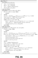
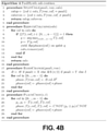
- Figure 4 illustrates the pseudo code of the algorithm according to an embodiment of the method.
- H ⁇ 1 X 1 + ⁇ 2 Z 2 Y 3 + ⁇ 3 X 1 Y 3 + ⁇ 4 X 1 Y 2 Z 3
- This Hamiltonian product can be represented by the following table: Y Y Z Y X ⁇ ⁇ Y Y Z Y X ⁇ X ⁇
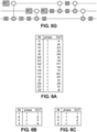
- the corresponding rotation circuit is illustrated on figure 5A .
- only the table is sufficient to obtain the synthesize circuit.
- step S2 the pivot row is determined.
- row 0 is picked since it contains three Y entries, while the other rows contain at most only two same entries.
- step S5 is directly performed.
- the target row in this case will be row 2 since it contains two X entries interacting with two Y entries of the pivot row
- a conjugation by a X rotation gate is performed on row 0 and a conjugation of Hadamard is performed on row 2, producing the circuit illustrated on figure 5B .
- a CNOT gate is then inserted from qubit 0 to qubit 2 (corresponding respectively to row 0 and row 2) and all rotation axis through the CNOT gate is conjugated.
- the obtained rotation circuit is illustrated on figure 5C . these steps corresponds to step S6.
- Figure 6A illustrates the CNOT conjugation table.
- Figure 6B illustrated the Hadamard conjugation table.
- Figure 6C illustrates the conjugation table of the RX( ⁇ /2) gate.
- the method then knows exactly what will be the result of the insertion of the predetermined gates, which ensure having an optimized result.
- the X, Y, and/or Z rotation entries in the table can be replaced by identities according to the result of the conjugation.
- the obtained table will be: ⁇ ⁇ Y ⁇ X ⁇ ⁇ Y Y Z Y Z X Z X
- the corresponding circuit is illustrated on figure 5C , in which the first two parities ZY and ZZ are replaced by the respective 1-qubit rotations along Y axis and Z axis.
- step S3 is performed again.
- the table can be re-written in a sub-table in which the columns having only one rotation entry are withdrawn since these columns become trivial.
- the sub-table is then: Y ⁇ X Y Y Z X Z X
- pivot row 0 comprises an identity entry column 1 of the sub-table, a new pivot row is determined.
- the new pivot row is row 2 since it contains two X entries.
- the target row will be row 1 which does not contain identity.
- Row 1 is then conjugated by a RX( ⁇ /2) gate followed by a CNOT gate from row 1 to row 2, leading to the rotation circuit illustrated on figure 5D .
- the table, or the sub-table is rewritten to insert identity entries in place of the rotation entries X, Y and/or Z in the pivot row.
- the sub-table can be re-written in a second sub-table being: Y X Z Y X ⁇
- the method recursively calls the pivot row 0. Since row 0 does not contain any identity, the target row is directly determined. In this case, the target row is row 1 since it contains the maximum non-identity entries.
- the final circuit that can be returned by the method is obtained by removing the Clifford circuit portion at the end of the rotation circuit. This circuit is illustrated on figure 5G .
- the method provides a routine to synthesize a single layer of a Trotter-Suzuki expansion.
- this synthesizing can be generalized to all the layers of a Trotter-Suzuki expansion.
- the method is applied iteratively i times to the circuit in order to synthesize the i individual layers.
- the Clifford circuit actually corresponds to a correction to apply to the qubits in order to fix the qubits.
- the process for synthesizing quantum circuits for Trotter-Suzuki n-order expansion as described frees itself from the fixing by commuting the Clifford corrections to the Clifford circuit portion and either conjugating the final observable to measure through the resulting overall Clifford correction, or altering the final measurements via standard methods.
Landscapes
- Engineering & Computer Science (AREA)
- Theoretical Computer Science (AREA)
- General Physics & Mathematics (AREA)
- Physics & Mathematics (AREA)
- General Engineering & Computer Science (AREA)
- Data Mining & Analysis (AREA)
- Mathematical Analysis (AREA)
- Artificial Intelligence (AREA)
- Computational Mathematics (AREA)
- Condensed Matter Physics & Semiconductors (AREA)
- Software Systems (AREA)
- Evolutionary Computation (AREA)
- Mathematical Physics (AREA)
- Mathematical Optimization (AREA)
- Pure & Applied Mathematics (AREA)
- Computing Systems (AREA)
- Quality & Reliability (AREA)
- Computer Hardware Design (AREA)
- Optical Modulation, Optical Deflection, Nonlinear Optics, Optical Demodulation, Optical Logic Elements (AREA)
- Complex Calculations (AREA)
Abstract
• Providing a table of p number of rows and m number of columns, where p is a number of qubits and m a number of rotations in the quantum circuit, and where the table comprises X, Y, Z or I entry corresponding to the respective rotations of the qbits;
• Determining a pivot row,
and recursively, until all rotations of the product of Pauli rotations are 1-qubit rotations:
• Determine a target row,
• Conjugate the target row with the pivot row by insertion of predetermined quantum gates on the qubits corresponding to the target row and/or pivot row by calling, at each recursive call, entries of the same type of the pivot row and by always calling first the identity entry.
Description
- The invention concerns methods for synthesizing product of Pauli rotations in a quantum circuit and processes for synthesizing quantum circuits for Trotter-Suzuki n-order expansion.
- From a first prior art Quantum Science and Technology, Amy et al, together with Architecture-aware synthesis of phase polynomials for NISQ devices, Meijer et al, a method is known for synthesise quantum circuits for phase polynomials, for quantum circuits containing only CNOT quantum gates and rotation along Z axis. This method is also known as Graysynth algorithm. With this method, it is possible to obtain a compiled quantum circuit comprising a low number of CNOT gates. However, this method can be applied only to circuits comprising only the two above-mentioned quantum gates.
- From a second prior art A Generic Strategy for the Unitary Coupled Cluster Ansatz, Cowtan et al, a method is known to compile circuit by partitioning Pauli exponential terms into mutually commuting sets that are then diagonalised using Clifford circuits, to finally obtain compiled circuits while reducing depth and number of CNOT quantum gates. This method particularly performs basis changes to obtain only rotational quantum gates along Z-axis.
- Although the results are optimized, this method requires an exponential number of steps and time to obtain these results, since it is needed, as a preprocessing step, to first modify the circuit to obtain only rotational quantum gates along Z-axis, which is complex and time consuming.
- These known solutions make it possible to obtain a compiled circuit, although a primary condition of having only rotational quantum gates along Z-axis is required.
- The invention at least partially remedies the shortcuts of the prior art and optimizes the synthesizing of quantum circuit comprising Pauli rotations by generalizing the Graysynth algorithm.
- Therefore, according to the invention, it will be beneficial to transform the quantum circuit to obtain a table showing clearly the entanglement between the qubits, and the rotation that applies to each qubit, or to be provided with a table corresponding to the quantum circuit. Advantageously, the rotations in te quantum circuit will present small angles.
- On this basis, the method will recursively choose a pivot row on which to apply a reduced number and predetermined types of quantum gates to finally obtain a synthesized quantum circuits independently of the type of rotational quantum gates initially present in the quantum circuit.
- The method according to the invention therefore enables the compiling of a quantum circuit in a way with improved automation and optimization and suitable for any Paul rotations.
- Finally, the method according to the invention leads to a synthesized quantum circuit with an optimized CNOT count.
- To this aim, there is provided a method for synthesizing product of Pauli rotations, wherein said product of Pauli rotations comprises at least two different types of X, Y, and/or Z n-qbits Pauli rotations and identities (I), said method comprising:
- providing a table of p number of rows and m number of columns, where p is a number of qubits and m a number of rotations in the quantum circuit, and where the table comprises X, Y, Z or I entry corresponding to the respective rotations of the qbits,
- a step of determining a pivot row as being the row comprising a maximum number of the same type of X, Y, Z or I entry,
and wherein said method performs recursively, until all qubits performs only 1-qubit-rotation:- ∘ a step of determining if the pivot row comprises at least one identity entry and
- ▪ if yes, determine a new pivot row having the maximum same entries, and being different from the first determined pivot row,
- ▪ if no, performs the next step directly,
- ∘ a step of determining a target row among remaining rows, said target row containing a maximum of non-identity entries interacting with the entries of the pivot row ,
- ∘ a step of conjugating said pivot row and said target row by inserting a predetermined type of quantum gates on their respective qubits in order to bring the X, Y or Z entry of at least the pivot row to I entry,
- ∘ a step of rewriting the table according to the result of the conjugation, by replacing the X, Y and/or Z entry of at least the pivot row by an identity entry,
- ∘ a step of determining if the pivot row comprises at least one identity entry and
- returning the synthesized table.
- The recursive call on the pivot row, while always calling first the identity entry, allows the generalization of Graysynth algorithm to any arbitrary Pauli product, without requiring a first change to modify all the rotations to Z rotations.
- In an embodiment, the table is provided after:
- Providing a quantum circuit corresponding to the product of Pauli rotations,
- Rewriting the quantum circuits in the form of a table.
- Hence, the method can be applied without having a quantum circuit by only being provided with the table. In other hand, the method can be applied without being provided with the table already written, the table can be obtained from the quantum circuit.
- In an embodiment, the method further comprises:
- providing a rotation circuit representing the X, Y and/or Z n-qubits Pauli operators,
- at each conjugation step, inserting the predetermined type of quantum gates on their respective qubits in the rotation circuit,
- according to the result of the conjugation, rewriting the rotation circuit by replacing the n-qbits rotation of at least the pivot row by a 1-qbit rotation, returning the synthesized rotation circuit.
- Then, the method can be applied with the table and/or the rotation circuit.
- In an embodiment, the method further comprises:
- providing a phase gadget sequence representing the X, Y and/or Z n-qubits Pauli operators,
- at each conjugation step, inserting the predetermined type of quantum gates on their respective qubits in the phase gadget sequence,
- according to the result of the conjugation, rewriting the phase gadget sequence by replacing the n-qbits rotation of at least the pivot row by a 1-qbit rotation,
- returning the phase gadget sequence.
- In an embodiment, the conjugation step further comprises:
- inserting the predetermined type of quantum gates on their respective qubits in the rotation circuit before the X, Y and/or Z n-qubits Pauli operators, and
- inserting reversed quantum gates on the same qubits in the rotation circuit, after the X, Y and/or Z n-qubits Pauli operators.
- The reversed quantum gates ensure to have the same circuit at the end.
- In an embodiment, the method comprises, before determining the pivot row:
- suppressing the columns of the table that contain only one rotation,
- and inserting a corresponding phase gate in the quantum circuit.
- During this step, the trivial columns are withdrawn from the table, such that the method does not take into account these columns and rotations. It allows a better optimization in term of time and computation.
- In an embodiment, the conjugating step comprises:
- one or several insertions of Clifford quantum gates between the pivot row and the target row in the quantum circuit.
- First it allows to locally changing a row of the table to transform a Pauli operator into another one, and then CNOT is easily transposable on the parity table by distributing a row onto another row.
- In an embodiment, the Clifford quantum gates preferably comprise :
- RX(π/2) quantum rotation gates and Hadamard quantum gates,
- CNOT quantum gates.
- Since the conjugation tables of these gates are known, they can be applied easily with a sure result at the end.
- In an embodiment, the method further comprises an optimizing step wherein the returned synthesized rotation circuit is split to obtain:
- A first sub-quantum circuit comprising only the inserted Clifford quantum gates and the 1-qubit rotations,
- a second sub-quantum circuit comprising only the reversed Clifford gates,
- and wherein only the first sub-circuit is executed.
- Since the properties of a Clifford circuit are well known, only the first subcircuit can be executed. The second sub-circuit can be taken into account by modifying the measurements at the end of the method, for example.
- In an embodiment, a Clifford correction corresponding to the second sub-circuit is applied to the first sub-circuit.
- The Clifford correction can be calculated by various methods know in the art. The final execution of the circuit is then easier and more optimized.
- In an embodiment, the product of Pauli rotations corresponds to a Hamiltonian simulation.
- There is also provided a method for generalizing an algorithm configured to synthesize a diagonal product of Pauli rotations to synthesize a product of Pauli rotations comprising X, Y and Z rotations, the method comprising:
- providing a table of p number of rows and m number of columns, where p is a number of qubits and m a number of rotations, and where the table comprises X, Y, Z or I entry corresponding to the respective rotations of the qbits;
- determining a pivot row,
and recursively, until all rotations of the product of Pauli rotations are 1-qubit rotations: - determine a target row,
- conjugate the target row with the pivot row by insertion of predetermined quantum gates on the qubits corresponding to the target row and/or pivot row by calling, at each recursive call, entries of the same type of the pivot row and by always calling first the identity entry.
- There is also provided a process for synthesizing quantum circuits for Trotter-Suzuki n-order expansion comprising: applying iteratively to each layer of the quantum circuit the method for synthesizing Pauli rotations in a quantum circuit according to the application.
-
-
Figures 1A to 1E illustrate a phase gadget sequence on which the Graysynth algorithm is applied. -
Figure 2 shows a pseudo code of Graysynth algorithm. -
Figure 3 illustrates the steps of the method according to an embodiment. -
Figure 4A and4B show a pseudo code of the method according to an embodiment. -
Figures 5A to 5G illustrates a rotation circuit on which the method according to one embodiment is applied. -
Figure 6A to 6C illustrate the conjugation tables of CNOT, RX(π/2) and Hadamard quantum gates. -
Figure 7 illustrates a Trotter-Suzuki n order expansion circuit. -
Figures 1A to 1E illustrates a particular example of a phase polynomial synthesis, performed through Graysynth algorithm. - The Graysynth algorithm is made for the synthesis of the propagator of a diagonal Hamiltonian H = Σ ihiPi. when H is diagonal, it can be described as a collection of parities and its propagator e-iγH is exactly the product of Πie-αiγPi where each Pi is composed solely of Pauli Z rotations. Since all these terms commute, the product can be implemented in whatever order.
- Phase polynomials form a particular set of unitary operators that can be implemented using only CNOT and rotation along Z-axis (or RZ gate) gates.
- Below is described an exemplary application of the Graysynth algorithm for the following Pauli product:

- This product can be described in the form of a phase gadget sequence, using ZX calculus for example, as illustrated in
figure 1A . Each of these gadget comprise a collection of striped Z nodes attached to a pair of crossed X nodes and nodes carrying the rotation angle α1, α2, α3. Each line corresponds to one qubit q0, q1, q2. - The synthesis starts by inserting a phase gate in place of the last gadget carrying the rotation angle α3 since this gadget is trivial and does not require and CNOT gate for its implementation. Indeed, the rotation angle only applies on qubit q2. The inserted phase gate can be commuted to the beginning of the phase gadget sequence. The result of this first step is illustrated on
figure 1B . - Next, the purpose being of having only phase gadgets acting on only one qubit, some CNOT gates are injected in the phase gadget sequence.
- More precisely, as illustrated on
figure 1C , a pair of CNOT gates is injected in the phase gadget sequence, before the two gadgets carrying the rotations angles α1, α2. - As described above, since the terms commute, the quantum gates and the phase gadget can be placed in any order.
- Then, in
figure 1D , one of the CNOT gate is pulled at the end of the remaining gadget carrying the rotation angles α1, α2, effectively conjugating these gadgets with the pair of CNOT. - The gadget carrying the rotation angle α1 can be replaced with a phase gadget that will lodge itself against the first CNOT gate. Then the last remaining gadget carrying the rotation angle α2 is conjugated with a last CNOT gate?.
- The final obtained phase gadget sequence is shown on
figure 1E . The quantum circuit obtained at the end of the Graysynth algorithm, for this particular example, comprises three phase gadgets carrying the rotation angles α1, α2, α3, and four CNOT gates. - Graysynth algorithm performs the conjugation of the phase gadgets by CNOT gates in order to reduce their arity. The algorithm is called recursively until all gadgets are of
arity 1, or, in other words, until all the qubits perform only 1-qubit rotation. - The recursive structure of the Graysynth algorithm can also be illustrated by use of a table depicting the Pauli product.
- The gadgets are represented in a p x m table, where each column represents a parity and each line represents a qubit. For example, the Paul product described above:

- Can be represented by the following table:

- At each step of recursion, the Graysynth algorithm determines a pivot row in the table, by looking for the row having the most 0s or 1s among all the remaining columns.
- In the table, the 1s represent the Z rotations and the 0s represent the identities.
- The algorithm is then called recursively in two successive steps. First, the algorithm is called recursively on the columns containing 0s on the pivot row while removing the pivot row from the possible interacting rows. Second, the algorithm is called recursively on the columns containing 1s on the pivot row while looking for a target row that shares the largest possible number of 1s with the pivot row among the remaining interacting rows
- As an example,
figure 2 illustrates the pseudo code of Graysynth algorithm. -
Figure 3 illustrates the step of the method according to an embodiment. - To generalize the Graysynth algorithm to any type of Pauli product, including product comprising rotations along X, Y and/or Z-axis, the Pauli product is rewritten with a table of p x m dimension, with p the number of qubits, m the number of rotations, and a list of corresponding angles α of length m.
- In an embodiment, the table is provided and there is no step of re-writing the Hamiltonian product (or "Hamiltonian"). This step corresponds to step S1 of
figure 3 . - More specifically, the generalization of Graysynth algorithm, according to the present application, allows synthesizing any type of Hamiltonian.
- In contrary with Graysynth algorithm, the above described Hamiltonian comprises arbitrary rotations including X, Y and Z rotations and identities (represented by hyphens in the table).
- After determining a pivot row, Graysynth recursively calls the 0s entries in the pivot row, and then the 1s entries in the pivot row.
- At each recursive calls, CNOT gates are inserted between the pivot row and the target row as described above.
- To generalize the Graysynth algorithm, instead of sorting the columns according to two categories being I entries and Z entries, the present method sorts the columns into four categories, being I, X, Y and Z entries.
- The pivot row is determined at step S2 as the row having the most similar entries between I, X, Y and Z entries.
- Then, the method determines if the pivot row comprises identities entries at step S3.
- If the pivot row does not comprise identity entries, the method directly performs step S5.
- If the pivot row comprises identities entries, a new pivot row is determined at step S4. This new pivot row is different from the pivot row determined at step S2. The new pivot row is the pivot row having the maximum number of same entries.
- Step S3 to S5 allow ensuring that, when the method performs a call on the pivot row for its X, Y or Z entries, no new entry of the called entry occurs. Then, the recursive call begins with a call on the identities entries of the pivot row instead of a X, Y or Z entry.
- At step S5, a target row is determined. The target row is determined as the row comprising the maximum of same non-identities entries, i.e. X, Y and/or Z entries, that interacts with the pivot row.
- At step S6, the target and pivot row are conjugated by inserting predetermined quantum gates on their respective qubits in order to bring the entries of the pivot row to identities entries.
- In an example, the quantum gates are Clifford quantum gates.
- For example, the quantum gates are rotation along X axis quantum gates (or X rotation gates or RX(π/2)), Hadamard quantum gates and CNOT quantum gates.
- The X rotation gates and/or the Hadamard rotation gates can be applied on the qubit corresponding to the target row and/or the pivot row. The CNOT gates are inserted between the qubit corresponding to the pivot row and the qubit corresponding to the target row.
- At step S7, the table is rewritten by replacing the X, Y and/or Z entries by identity entries, according to the result of the conjugation performed at step S6.
- At step S8, the method recursively calls the pivot and performs step S3 on the pivot row, until all the qubits are of
arity 1, or said differently, until all the qubits perform 1-qubit rotation. - Then, the table is returned at step S9.
-
Figure 4 illustrates the pseudo code of the algorithm according to an embodiment of the method. - Below is described a non-limitative exemplary embodiment according to an embodiment of the method.
- The following Hamiltonian is considered to illustrate this example:

- This Hamiltonian product can be represented by the following table:

- The corresponding rotation circuit is illustrated on
figure 5A . - In an embodiment, only the table is sufficient to obtain the synthesize circuit.
- As described with reference to
figure 3 , at step S2 the pivot row is determined. In this example,row 0 is picked since it contains three Y entries, while the other rows contain at most only two same entries. - Since the pivot row does not contain any identity entry, step S5 is directly performed.
- The target row in this case will be
row 2 since it contains two X entries interacting with two Y entries of the pivot row - A conjugation by a X rotation gate is performed on
row 0 and a conjugation of Hadamard is performed onrow 2, producing the circuit illustrated onfigure 5B . - A CNOT gate is then inserted from
qubit 0 to qubit 2 (corresponding respectively torow 0 and row 2) and all rotation axis through the CNOT gate is conjugated. The obtained rotation circuit is illustrated onfigure 5C . these steps corresponds to step S6. - The conjugation and insertion of quantum gates can be performed by using the tables illustrated on
figures 6A to 6C . -
Figure 6A illustrates the CNOT conjugation table. The table is read as follow: CNOT(IN)CNOT = phase.OUT. -
Figure 6B illustrated the Hadamard conjugation table. -
Figure 6C illustrates the conjugation table of the RX(π/2) gate. - The method then knows exactly what will be the result of the insertion of the predetermined gates, which ensure having an optimized result.
- Then, according to the result of the conjugation, the X, Y, and/or Z rotation entries in the table can be replaced by identities according to the result of the conjugation.
- In this particular example, the obtained table will be:

- The corresponding circuit is illustrated on
figure 5C , in which the first two parities ZY and ZZ are replaced by the respective 1-qubit rotations along Y axis and Z axis. - Then, since there are still qubits performing 1-qubit rotation in the rotation circuit, and still q-bit of
arity 2 or more in the table, step S3 is performed again. - In an embodiment, the table can be re-written in a sub-table in which the columns having only one rotation entry are withdrawn since these columns become trivial. The sub-table is then:

- The method recursively calls the
pivot row 0. Sincepivot row 0 comprises anidentity entry column 1 of the sub-table, a new pivot row is determined. - The new pivot row is
row 2 since it contains two X entries. The target row will berow 1 which does not contain identity. -
Row 1 is then conjugated by a RX(π/2) gate followed by a CNOT gate fromrow 1 torow 2, leading to the rotation circuit illustrated onfigure 5D . - On the rotation circuit of
figure 5D , it can be seen that a new 1-qubit rotation gate Z has been inserted. - The table, or the sub-table, is rewritten to insert identity entries in place of the rotation entries X, Y and/or Z in the pivot row. In this particular example, the sub-table can be re-written in a second sub-table being:

- Then, since all qubit are not of
arity 1, the method recursively calls thepivot row 0. Sincerow 0 does not contain any identity, the target row is directly determined. In this case, the target row isrow 1 since it contains the maximum non-identity entries. - By conjugating
row 1 by a Hadamard gate, an RX(π/2) gate and inserting a CNOT gate betweenqubit 0 andqubit 1, the rotation circuit offigure 5E will be obtained. - Finally, with a last recursive call on the remaining column, the circuit of
figure 5F is obtained. - The final circuit that can be returned by the method is obtained by removing the Clifford circuit portion at the end of the rotation circuit. This circuit is illustrated on
figure 5G . - The method described with reference to
figures 1 to 5F can be implemented to synthesize circuits for Trotter-Suzuki n-order expansion according to an embodiment. - More precisely, the method provides a routine to synthesize a single layer of a Trotter-Suzuki expansion.
- In an embodiment, this synthesizing can be generalized to all the layers of a Trotter-Suzuki expansion. The method is applied iteratively i times to the circuit in order to synthesize the i individual layers.
- This iteration will lead to the quantum circuit illustrated on
figure 7 , where Ππie-(αi/n)Pi corresponds to an ordered product of Pauli rotations as obtained onfigure 5G and which corresponds to an Hamiltonian, and where Cπ corresponds to the Clifford circuit as removed fromfigure 5G . - The Clifford circuit actually corresponds to a correction to apply to the qubits in order to fix the qubits.
- The optimization and correction of such Clifford circuits is known in the art.
- The process for synthesizing quantum circuits for Trotter-Suzuki n-order expansion as described frees itself from the fixing by commuting the Clifford corrections to the Clifford circuit portion and either conjugating the final observable to measure through the resulting overall Clifford correction, or altering the final measurements via standard methods.
Claims (12)
- Method for synthesizing product of Pauli rotations, wherein said product of Pauli rotations comprises at least two different types of X, Y, and/or Z n-qbits Pauli rotations and identities (I), said method comprising:• providing a table of p number of rows and m number of columns, where p is a number of qubits and m a number of rotations in the quantum circuit, and where the table comprises X, Y, Z or I entry corresponding to the respective rotations of the qbits,• a step of determining a pivot row as being the row comprising a maximum number of the same type of X, Y, Z or I entry,
and wherein said method performs recursively, until all qubits performs only 1-qubit-rotation:∘ a step of determining if the pivot row comprises at least one identity entry and▪ if yes, determine a new pivot row having the maximum same entries, and being different from the first determined pivot row,▪ if no, performs the next step directly,∘ a step of determining a target row among remaining rows, said target row containing a maximum of non-identity entries interacting with the entries of the pivot row ,∘ a step of conjugating said pivot row and said target row by inserting a predetermined type of quantum gates on their respective qubits in order to bring the X, Y or Z entry of at least the pivot row to I entry,∘ a step of rewriting the table according to the result of the conjugation, by replacing the X, Y and/or Z entry of at least the pivot row by an identity entry,• returning the synthesized table. - Method according to claim 1, wherein the table is provided after:• providing a quantum circuit corresponding to the product of Pauli rotations,• rewriting the quantum circuits in the form of a table.
- Method according to any of claims 1 or 2, further comprising:• providing a rotation circuit representing the X, Y and/or Z n-qubits Pauli operators,• at each conjugation step, inserting the predetermined type of quantum gates on their respective qubits in the rotation circuit,• according to the result of the conjugation, rewriting the rotation circuit by replacing the n-qbits rotation of at least the pivot row by a 1-qbit rotation,• returning the synthesized rotation circuit.
- Method according to claim 3, wherein the conjugation step further comprises:• inserting the predetermined type of quantum gates on their respective qubits in the rotation circuit before the X, Y and/or Z n-qubits Pauli operators, and• inserting reversed quantum gates on the same qubits in the rotation circuit, after the X, Y and/or Z n-qubits Pauli operators.
- Method according to any of claims 1 to 3, comprising, before determining the pivot row:• suppressing the columns of the table that contain only one rotation,• and inserting a corresponding phase gate in the quantum circuit.
- Method according to any of claims 2 to 4, wherein the conjugating step comprises:• one or several insertions of Clifford quantum gates between the pivot row and the target row in the quantum circuit.
- Method according to claim 6, wherein the Clifford quantum gates preferably comprise :• RX(π/2) quantum rotation gates and Hadamard quantum gates,• CNOT quantum gates.
- Method according to claims 3 and any of claims 6 or 7, further comprising an optimizing step wherein the returned synthesized rotation circuit is split to obtain:• A first sub-quantum circuit comprising only the inserted Clifford quantum gates and the 1-qubit rotations,• a second sub-quantum circuit comprising only the reversed Clifford gates, and wherein only the first sub-circuit is executed.
- Method according to claim 8, wherein a Clifford correction corresponding to the second sub-circuit is applied to the first sub-circuit.
- Method according to any of claims 1 to 9, wherein the product of Pauli rotations corresponds to a Hamiltonian simulation.
- Process for synthesizing quantum circuits for Trotter-Suzuki n-order expansion comprising:• applying iteratively to each layer of the quantum circuit the method for synthesizing Pauli rotations in a quantum circuit according to any of claims 1 to 10.
- Method for generalizing an algorithm configured to synthesize a diagonal product of Pauli rotations to synthesize a product of Pauli rotations comprising X, Y and Z rotations, the method comprising:• Providing a table of p number of rows and m number of columns, where p is a number of qubits and m a number of rotations, and where the table comprises X, Y, Z or I entry corresponding to the respective rotations of the qbits;• Determining a pivot row,
and recursively, until all rotations of the product of Pauli rotations are 1-qubit rotations:• Determine a target row,• Conjugate the target row with the pivot row by insertion of predetermined quantum gates on the qubits corresponding to the target row and/or pivot row by calling, at each recursive call, entries of the same type of the pivot row and by always calling first the identity entry.
Priority Applications (2)
| Application Number | Priority Date | Filing Date | Title |
|---|---|---|---|
| EP20305969.6A EP3965022A1 (en) | 2020-09-02 | 2020-09-02 | Method for synthesizing product of pauli rotations in a quantum circuit and process for synthesizing quantum circuits for trotter-suzuki n-order expansion |
| US17/458,758 US12118432B2 (en) | 2020-09-02 | 2021-08-27 | Method for synthesizing product of Pauli rotations in a quantum circuit and process for synthesizing quantum circuits for Trotter-Suzuki n-order expansion |
Applications Claiming Priority (1)
| Application Number | Priority Date | Filing Date | Title |
|---|---|---|---|
| EP20305969.6A EP3965022A1 (en) | 2020-09-02 | 2020-09-02 | Method for synthesizing product of pauli rotations in a quantum circuit and process for synthesizing quantum circuits for trotter-suzuki n-order expansion |
Publications (1)
| Publication Number | Publication Date |
|---|---|
| EP3965022A1 true EP3965022A1 (en) | 2022-03-09 |
Family
ID=73476074
Family Applications (1)
| Application Number | Title | Priority Date | Filing Date |
|---|---|---|---|
| EP20305969.6A Pending EP3965022A1 (en) | 2020-09-02 | 2020-09-02 | Method for synthesizing product of pauli rotations in a quantum circuit and process for synthesizing quantum circuits for trotter-suzuki n-order expansion |
Country Status (2)
| Country | Link |
|---|---|
| US (1) | US12118432B2 (en) |
| EP (1) | EP3965022A1 (en) |
Families Citing this family (3)
| Publication number | Priority date | Publication date | Assignee | Title |
|---|---|---|---|---|
| US20230196155A1 (en) * | 2021-12-20 | 2023-06-22 | International Business Machines Corporation | Obfuscation of quantum circuits |
| KR102687526B1 (en) * | 2023-12-29 | 2024-07-24 | 부산대학교 산학협력단 | Apparatus for Low CNOT-count quantum Point-doubling Circuit |
| US20260111773A1 (en) * | 2024-10-17 | 2026-04-23 | International Business Machines Corporation | Obscuring proprietary information in quantum circuits using virtual quantum gates |
Family Cites Families (12)
| Publication number | Priority date | Publication date | Assignee | Title |
|---|---|---|---|---|
| US20060123363A1 (en) * | 2004-12-07 | 2006-06-08 | Williams Colin P | Method and apparatus for automated design of quantum circuits |
| KR101517361B1 (en) * | 2014-01-24 | 2015-05-06 | 고려대학교 산학협력단 | Method for correcting error of imperfect entangled qubit in receiver |
| US10366339B2 (en) * | 2014-11-21 | 2019-07-30 | Microsoft Technology Licensing, Llc | Method for efficient implementation of diagonal operators over clifford+T basis |
| US10922457B2 (en) * | 2017-10-19 | 2021-02-16 | University Of Maryland | Automated optimization of large-scale quantum circuits with continuous parameters |
| US11562277B2 (en) * | 2017-12-28 | 2023-01-24 | University Of Maryland, College Park | Use of global interactions in efficient quantum circuit constructions |
| CA3253349A1 (en) * | 2018-05-31 | 2025-03-18 | Oti Lumionics Inc. | Methods and systems for solving a problem on a quantum computer |
| US11475345B2 (en) * | 2018-12-06 | 2022-10-18 | International Business Machines Corporation | Controlled NOT gate parallelization in quantum computing simulation |
| US11049038B2 (en) * | 2019-03-29 | 2021-06-29 | Alibaba Group Holding Limited | Methods and systems for optimizing quantum circuits |
| WO2021154350A2 (en) * | 2019-10-22 | 2021-08-05 | President And Fellows Of Harvard College | Quantum generative models for sampling many-body spectral functions |
| US11551131B2 (en) * | 2020-02-27 | 2023-01-10 | International Business Machines Corporation | Hamiltonian simulation based on simultaneous-diagonalization |
| US11200360B1 (en) * | 2020-06-10 | 2021-12-14 | International Business Machines Corporation | Synthesis of a quantum circuit |
| GB2622065B (en) * | 2022-09-01 | 2024-11-20 | Advanced Risc Mach Ltd | Counter integrity tree |
-
2020
- 2020-09-02 EP EP20305969.6A patent/EP3965022A1/en active Pending
-
2021
- 2021-08-27 US US17/458,758 patent/US12118432B2/en active Active
Non-Patent Citations (7)
| Title |
|---|
| ALEXANDER COWTAN ET AL: "Phase Gadget Synthesis for Shallow Circuits", ARXIV.ORG, CORNELL UNIVERSITY LIBRARY, 201 OLIN LIBRARY CORNELL UNIVERSITY ITHACA, NY 14853, 4 June 2019 (2019-06-04), XP081656272, DOI: 10.4204/EPTCS.318.13 * |
| AMY, QUANTUM SCIENCE AND TECHNOLOGY |
| ARIANNE MEIJER-VAN DE GRIEND ET AL: "Architecture-aware synthesis of phase polynomials for NISQ devices", ARXIV.ORG, CORNELL UNIVERSITY LIBRARY, 201 OLIN LIBRARY CORNELL UNIVERSITY ITHACA, NY 14853, 13 April 2020 (2020-04-13), XP081643345 * |
| COWTAN ALEXANDER ET AL: "A Generic Compilation Strategy for the Unitary Coupled Cluster Ansatz", 27 August 2020 (2020-08-27), pages 1 - 26, XP055775617, Retrieved from the Internet <URL:https://arxiv.org/pdf/2007.10515.pdf> [retrieved on 20210212] * |
| COWTAN ET AL., A GENERIC STRATEGY FOR THE UNITARY COUPLED CLUSTER ANSATZ |
| MATTHEW AMY ET AL: "On the CNOT-complexity of CNOT-PHASE circuits", ARXIV.ORG, CORNELL UNIVERSITY LIBRARY, 201 OLIN LIBRARY CORNELL UNIVERSITY ITHACA, NY 14853, 5 December 2017 (2017-12-05), XP081410908, DOI: 10.1088/2058-9565/AAD8CA * |
| MEIJER ET AL., ARCHITECTURE-AWARE SYNTHESIS OF PHASE POLYNOMIALS FOR NISQ DEVICES |
Also Published As
| Publication number | Publication date |
|---|---|
| US12118432B2 (en) | 2024-10-15 |
| US20220067566A1 (en) | 2022-03-03 |
Similar Documents
| Publication | Publication Date | Title |
|---|---|---|
| US12118432B2 (en) | Method for synthesizing product of Pauli rotations in a quantum circuit and process for synthesizing quantum circuits for Trotter-Suzuki n-order expansion | |
| Fomitchev et al. | Lock-free linked lists and skip lists | |
| US11062079B2 (en) | Method for compiling a quantum circuit on a quantum processor with trapped ions | |
| Reynolds | Definitional interpreters for higher-order programming languages | |
| Gheorghiu et al. | Reducing the CNOT count for Clifford+ T circuits on NISQ architectures | |
| US12307176B2 (en) | System and method for reducing CNOT count in Clifford+T circuits on connectivity constrained architectures | |
| JPH04229374A (en) | Method and system for processing parts list and for processing project network | |
| Staudacher et al. | Reducing 2-qubit gate count for ZX-calculus based quantum circuit optimization | |
| US8280836B2 (en) | Converting unordered graphs to oblivious read once ordered graph representation | |
| US11900221B1 (en) | Error correction decoding techniques for lattice surgery | |
| Ren et al. | Efficient preparation of solvable anyons with adaptive quantum circuits | |
| US20050021583A1 (en) | Determination of one or more variables to receive value changes in local search solution of integer programming problem | |
| Winderl et al. | A recursively partitioned approach to architecture-aware ZX polynomial synthesis and optimization | |
| Vandaele et al. | Optimal number of parametrized rotations and Hadamard gates in parametrized Clifford circuits with non-repeated parameters | |
| Heyfron et al. | A quantum compiler for qudits of prime dimension greater than 3 | |
| Hanus | Efficient implementation of narrowing and rewriting | |
| van der Aalst | Reduction using induced subnets to systematically prove properties for free-choice nets | |
| Prenner et al. | An implementation of backtracking for programming languages | |
| Topor | The correctness of the Schorr-Waite list marking algorithm | |
| Escobedo et al. | Roundoff-error-free basis updates of LU factorizations for the efficient validation of optimality certificates | |
| EP1628206A2 (en) | Method and device for modular multiplication | |
| Chen et al. | Recursive methods for synthesizing permutations on limited-connectivity quantum computers | |
| US20220222320A1 (en) | Method for synthesizing a product of Pauli rotations | |
| Guessarian | Program transformations and algebraic semantics | |
| US20020091984A1 (en) | Method of reducing finite controlling automata and corresponding computer-readable medium |
Legal Events
| Date | Code | Title | Description |
|---|---|---|---|
| PUAI | Public reference made under article 153(3) epc to a published international application that has entered the european phase |
Free format text: ORIGINAL CODE: 0009012 |
|
| STAA | Information on the status of an ep patent application or granted ep patent |
Free format text: STATUS: THE APPLICATION HAS BEEN PUBLISHED |
|
| AK | Designated contracting states |
Kind code of ref document: A1 Designated state(s): AL AT BE BG CH CY CZ DE DK EE ES FI FR GB GR HR HU IE IS IT LI LT LU LV MC MK MT NL NO PL PT RO RS SE SI SK SM TR |
|
| STAA | Information on the status of an ep patent application or granted ep patent |
Free format text: STATUS: REQUEST FOR EXAMINATION WAS MADE |
|
| 17P | Request for examination filed |
Effective date: 20220330 |
|
| RBV | Designated contracting states (corrected) |
Designated state(s): AL AT BE BG CH CY CZ DE DK EE ES FI FR GB GR HR HU IE IS IT LI LT LU LV MC MK MT NL NO PL PT RO RS SE SI SK SM TR |
|
| P01 | Opt-out of the competence of the unified patent court (upc) registered |
Effective date: 20230330 |
|
| STAA | Information on the status of an ep patent application or granted ep patent |
Free format text: STATUS: EXAMINATION IS IN PROGRESS |
|
| 17Q | First examination report despatched |
Effective date: 20240322 |