EP3964891A1 - Illumination system and projection apparatus - Google Patents
Illumination system and projection apparatus Download PDFInfo
- Publication number
- EP3964891A1 EP3964891A1 EP21187430.0A EP21187430A EP3964891A1 EP 3964891 A1 EP3964891 A1 EP 3964891A1 EP 21187430 A EP21187430 A EP 21187430A EP 3964891 A1 EP3964891 A1 EP 3964891A1
- Authority
- EP
- European Patent Office
- Prior art keywords
- dichroic
- region
- excitation light
- light beams
- regions
- Prior art date
- Legal status (The legal status is an assumption and is not a legal conclusion. Google has not performed a legal analysis and makes no representation as to the accuracy of the status listed.)
- Granted
Links
Images
Classifications
-
- G—PHYSICS
- G03—PHOTOGRAPHY; CINEMATOGRAPHY; ANALOGOUS TECHNIQUES USING WAVES OTHER THAN OPTICAL WAVES; ELECTROGRAPHY; HOLOGRAPHY
- G03B—APPARATUS OR ARRANGEMENTS FOR TAKING PHOTOGRAPHS OR FOR PROJECTING OR VIEWING THEM; APPARATUS OR ARRANGEMENTS EMPLOYING ANALOGOUS TECHNIQUES USING WAVES OTHER THAN OPTICAL WAVES; ACCESSORIES THEREFOR
- G03B33/00—Colour photography, other than mere exposure or projection of a colour film
- G03B33/08—Sequential recording or projection
-
- G—PHYSICS
- G03—PHOTOGRAPHY; CINEMATOGRAPHY; ANALOGOUS TECHNIQUES USING WAVES OTHER THAN OPTICAL WAVES; ELECTROGRAPHY; HOLOGRAPHY
- G03B—APPARATUS OR ARRANGEMENTS FOR TAKING PHOTOGRAPHS OR FOR PROJECTING OR VIEWING THEM; APPARATUS OR ARRANGEMENTS EMPLOYING ANALOGOUS TECHNIQUES USING WAVES OTHER THAN OPTICAL WAVES; ACCESSORIES THEREFOR
- G03B21/00—Projectors or projection-type viewers; Accessories therefor
- G03B21/14—Details
- G03B21/20—Lamp housings
- G03B21/2006—Lamp housings characterised by the light source
- G03B21/2033—LED or laser light sources
- G03B21/204—LED or laser light sources using secondary light emission, e.g. luminescence or fluorescence
-
- G—PHYSICS
- G03—PHOTOGRAPHY; CINEMATOGRAPHY; ANALOGOUS TECHNIQUES USING WAVES OTHER THAN OPTICAL WAVES; ELECTROGRAPHY; HOLOGRAPHY
- G03B—APPARATUS OR ARRANGEMENTS FOR TAKING PHOTOGRAPHS OR FOR PROJECTING OR VIEWING THEM; APPARATUS OR ARRANGEMENTS EMPLOYING ANALOGOUS TECHNIQUES USING WAVES OTHER THAN OPTICAL WAVES; ACCESSORIES THEREFOR
- G03B21/00—Projectors or projection-type viewers; Accessories therefor
- G03B21/14—Details
- G03B21/20—Lamp housings
- G03B21/2006—Lamp housings characterised by the light source
- G03B21/2013—Plural light sources
-
- G—PHYSICS
- G03—PHOTOGRAPHY; CINEMATOGRAPHY; ANALOGOUS TECHNIQUES USING WAVES OTHER THAN OPTICAL WAVES; ELECTROGRAPHY; HOLOGRAPHY
- G03B—APPARATUS OR ARRANGEMENTS FOR TAKING PHOTOGRAPHS OR FOR PROJECTING OR VIEWING THEM; APPARATUS OR ARRANGEMENTS EMPLOYING ANALOGOUS TECHNIQUES USING WAVES OTHER THAN OPTICAL WAVES; ACCESSORIES THEREFOR
- G03B21/00—Projectors or projection-type viewers; Accessories therefor
- G03B21/14—Details
- G03B21/20—Lamp housings
- G03B21/2066—Reflectors in illumination beam
-
- G—PHYSICS
- G03—PHOTOGRAPHY; CINEMATOGRAPHY; ANALOGOUS TECHNIQUES USING WAVES OTHER THAN OPTICAL WAVES; ELECTROGRAPHY; HOLOGRAPHY
- G03B—APPARATUS OR ARRANGEMENTS FOR TAKING PHOTOGRAPHS OR FOR PROJECTING OR VIEWING THEM; APPARATUS OR ARRANGEMENTS EMPLOYING ANALOGOUS TECHNIQUES USING WAVES OTHER THAN OPTICAL WAVES; ACCESSORIES THEREFOR
- G03B21/00—Projectors or projection-type viewers; Accessories therefor
- G03B21/14—Details
- G03B21/20—Lamp housings
- G03B21/208—Homogenising, shaping of the illumination light
Definitions
- FIG. 5A is a light path schematic diagram of excitation light beams of an illumination system according to yet another embodiment of the disclosure
- FIG. 5B is a light path schematic diagram of a converted light beam of the illumination system of FIG. 5A
- an illumination system 100d of the embodiment is similar to the illumination system 100 of FIG. 1A , and differences there between are as follows.
- the first dichroic regions 210d respectively reflect the excitation light beams 111 to the color sequence generator 300.
Landscapes
- Physics & Mathematics (AREA)
- General Physics & Mathematics (AREA)
- Engineering & Computer Science (AREA)
- Multimedia (AREA)
- Optics & Photonics (AREA)
- Projection Apparatus (AREA)
Abstract

Description
- This application claims the priority of
China application serial no. 202010918648.2, filed on September 4, 2020 - The disclosure relates to an optical system and an apparatus, and particularly relates to an illumination system and a projection apparatus.
- Light source technology used in projectors has evolved from ultra-high pressure mercury lamps to red, green, and blue light-emitting diodes, and then to laser diode light sources along with market's requirements on projection brightness, color saturation, service life, and non-toxic environmental protection. Since the current high-brightness green laser diodes have not yet reached an appropriate price for projector applications, a main method currently used is to use a blue laser diode to excite a phosphor wheel to generate yellow green light, a color wheel is then used to filter out the required red and green light to be matched with blue light generated by the blue laser diode, and the three primary colors of red, green, and blue required for a projection image are thereby formed.
- However, in order to use the blue light generated by the blue laser diode as one of the three primary colors, a metal substrate of the phosphor wheel is provided with a hollow region and is inlaid with transparent glass, so that the blue light may penetrate through the phosphor wheel. Since the metal substrate is a substrate with a notch, in order to ensure that the phosphor wheel is to rotate in a balanced manner, dynamic balance weights are set in different regions on the metal substrate to reduce an eccentric phenomenon of the phosphor wheel in rotation. The various features of the above-mentioned phosphor wheel may increase structural and assembly complexity of the phosphor wheel, thereby increasing the costs of the phosphor wheel.
- The information disclosed in this BACKGROUND section is only for enhancement of understanding of the background of the described technology, and therefore it may contain information that does not form the prior art that is already known to a person of ordinary skill in the art. Further, the information disclosed in the BACKGROUND section does not mean that one or more problems to be resolved by one or more embodiments of the invention was acknowledged by a person of ordinary skill in the art.
- The disclosure is directed to an illumination system, which is adapted to effectively simplify a structure of a wavelength converter, increase a structural strength and a heat dissipation area of the wavelength converter, shorten dynamic balance adjustment work hours of the wavelength converter, simplify light paths of the illumination system, reduce a volume of the illumination system, and reduce complexity of electronic control, and that costs of the illumination system are effectively reduced.
- The disclosure provides a projection apparatus, which is adapted to effectively simplify a structure of a wavelength converter, increase a structural strength and a heat dissipation area of the wavelength converter, shorten dynamic balance adjustment work hours of the wavelength converter, simplify light paths of an illumination system, reduce a volume of the illumination system, and reduce complexity of electronic control, and that costs of the projection apparatus are effectively reduced.
- An embodiment of the disclosure provides an illumination system including an excitation light source array, a multi-region dichroic device, a color sequence generator, and a wavelength converter. The excitation light source array is configured to emit a plurality of excitation light beams. The multi-region dichroic device has a plurality of first dichroic regions and a plurality of non-dichroic regions that are alternately arranged in stripe shapes, wherein the first dichroic regions are respectively arranged on transmission paths of the excitation light beams. The color sequence generator has a light-transmitting region and at least one second dichroic region, wherein the excitation light beams from the excitation light source array are transmitted to the color sequence generator through the first dichroic regions of the multi-region dichroic device, and the light-transmitting region and the at least one second dichroic region are sequentially cut into the transmission paths of the excitation light beams. When the light-transmitting region is located on the transmission paths of the excitation light beams, the excitation light beams penetrate through the light-transmitting region. When the at least one second dichroic region is located on the transmission paths of the excitation light beams, the at least one second dichroic region respectively reflects the excitation light beams to the non-dichroic regions of the multi-region dichroic device. The excitation light beams from the color sequence generator are transmitted to the wavelength converter through the non-dichroic regions of the multi-region dichroic device. The wavelength converter converts the excitation light beams into a converted light beam. The converted light beam is transmitted back to the multi-region dichroic device, the converted light beam is transmitted to the color sequence generator through the multi-region dichroic device, and at least a portion of the converted light beam penetrates through the at least one second dichroic region.
- In one or more embodiments which could be combined with each other, the first dichroic regions respectively may allow the excitation light beams to penetrate through to be transmitted to the color sequence generator.
- In one or more embodiments which could be combined with each other, the non-dichroic regions may be a plurality of reflective mirror regions respectively reflecting the excitation light beams reflected by the at least one second dichroic region to the wavelength converter.
- In one or more embodiments which could be combined with each other, the first dichroic regions respectively may reflect the excitation light beams to the color sequence generator.
- In one or more embodiments which could be combined with each other, the non-dichroic regions may be a plurality of light-transmitting regions respectively allowing the excitation light beams reflected by the at least one second dichroic region to penetrate through to be transmitted to the wavelength converter.
- In one or more embodiments which could be combined with each other, the illumination system may further comprise a light converging lens.
- In one or more embodiments which could be combined with each other, the light converging lens may be disposed between the multi-region dichroic device and the color sequence generator.
- Preferably, the light converging lens may be configured to converge the excitation light beams coming from the first dichroic regions on the color sequence generator.
- Preferably, the light converging lens may be configured to transmit the excitation light beams reflected by the at least one second dichroic region to the non-dichroic regions.
- In one or more embodiments which could be combined with each other, a central optical axis of the light converging lens may have an off-axis amount relative to a central optical axis of the excitation light source array.
- In one or more embodiments which could be combined with each other, the wavelength converter may be a wavelength conversion wheel suitable for rotation.
- In one or more embodiments which could be combined with each other, the wavelength converter may have a wavelength conversion region.
- In one or more embodiments which could be combined with each other, the wavelength conversion region may be a complete ring-shaped region.
- In one or more embodiments which could be combined with each other, when the wavelength conversion wheel rotates, the excitation light beams may irradiate within the complete ring-shaped region.
- In one or more embodiments which could be combined with each other, the wavelength converter may be a wavelength conversion wheel and may have a wavelength conversion region.
- Preferably, the wavelength conversion region may be a C-shaped region.
- In one or more embodiments which could be combined with each other, when the wavelength conversion wheel rotates, the excitation light beams may irradiate within the C-shaped region.
- In one or more embodiments which could be combined with each other, the wavelength converter may be a wavelength conversion wheel and have a wavelength conversion region.
- In one or more embodiments which could be combined with each other, the wavelength conversion region may be provided with a first wavelength conversion layer and a second wavelength conversion layer.
- In one or more embodiments which could be combined with each other, the first wavelength conversion layer and the second wavelength conversion layer may be sequentially cut into the transmission paths of the excitation light beams coming from the multi-region dichroic device.
- In one or more embodiments which could be combined with each other, the first wavelength conversion layer may convert the excitation light beams into a first converted light beam when the first wavelength conversion layer is located on the transmission paths of the excitation light beams.
- In one or more embodiments which could be combined with each other, the second wavelength conversion layer may convert the excitation light beams into a second converted light beam when the second wavelength conversion layer is located on the transmission paths of the excitation light beams.
- In one or more embodiments which could be combined with each other, the at least one second dichroic region may comprise a first color filter region corresponding to the first converted light beam and a second color filter region corresponding to the second converted light beam for respectively allowing a portion of the first converted light beam and a portion of the second converted light beam to penetrate through.
- In one or more embodiments which could be combined with each other, the illumination system may further comprise a light converging lens, which may be disposed between the multi-region dichroic device and the wavelength converter.
- In one or more embodiments which could be combined with each other, a focal point at which the excitation light beams may be converged by the light converging lens which may not coincided with a wavelength conversion surface of the wavelength converter.
- In one or more embodiments which could be combined with each other, the illumination system may further comprise a light converging lens, which may be disposed between the multi-region dichroic device and the wavelength converter, and/or which may be configured to converge the excitation light beams on the wavelength converter.
- In one or more embodiments which could be combined with each other, the illumination system may further comprise a lens array or a diffuser plate.
- In one or more embodiments which could be combined with each other, the lens array or a diffuser plate may be disposed between the multi-region dichroic device and the wavelength converter to uniformize light spots of the excitation light beams formed on the wavelength converter.
- An embodiment of the disclosure provides a projection apparatus including the afore mentioned illumination system, a light valve, and a projection lens.
- The light valve may be arranged on the transmission paths of the excitation light beams and the converted light beam coming from the color sequence generator to convert the excitation light beams and the converted light beam into an image light beam.
- The projection lens may be arranged on a transmission path of the image light beam to project the image light beam out of the projection apparatus.
- In the illumination system and the projection apparatus of the embodiments of the disclosure, the excitation light beams emitted by the excitation light source array are transmitted to the color sequence generator and then divided into passing light beams and light beams reflected to the wavelength converter. As such, the structure of the wavelength converter may be effectively simplified, the structural strength and the heat dissipation area of the wavelength converter are increased, the dynamic balance adjustment work hours of the wavelength converter are shortened, the light paths of the illumination system are simplified, and the volume of the illumination system is reduced, and complexity of electronic control is decreased, and that the costs of the illumination system are effectively reduced.
- Other objectives, features and advantages of the present invention will be further understood from the further technological features disclosed by the embodiments of the present invention wherein there are shown and described preferred embodiments of this invention, simply by way of illustration of modes best suited to carry out the invention.
- The accompanying drawings are included to provide a further understanding of the invention, and are incorporated in and constitute a part of this specification. The drawings illustrate embodiments of the invention and, together with the description, serve to explain the principles of the invention.
-
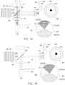
FIG. 1A is a light path schematic diagram of excitation light beams of an illumination system according to an embodiment of the disclosure. -
FIG.1B light path schematic diagram of a converted light beam of the illumination system ofFIG.1A. -
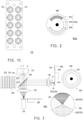
FIG. 1C is a schematic front view of an excitation light source array ofFIG. 1A . -
FIG. 2 is a schematic front view of a wavelength converter of an illumination system according to another embodiment of the disclosure. -
FIG. 3 is a light path schematic diagram of excitation light beams of an illumination system according to another embodiment of the disclosure. -
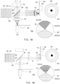
FIG. 4A is a light path schematic diagram of excitation light beams of an illumination system according to still another embodiment of the disclosure. -
FIG.4B light path schematic diagram of a converted light beam of the illumination system ofFIG.4A -
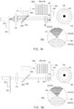
FIG. 5A is a light path schematic diagram of excitation light beams of an illumination system according to yet another embodiment of the disclosure. -
FIG.5B light path schematic diagram of a converted light beam of the illumination system ofFIG.5A. -
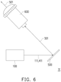
FIG. 6 is a light path schematic diagram of a projection apparatus of an embodiment of the disclosure. - In the following detailed description of the preferred embodiments, reference is made to the accompanying drawings which form a part hereof, and in which are shown by way of illustration specific embodiments in which the invention may be practiced. In this regard, directional terminology, such as "top," "bottom," "front," "back," etc., is used with reference to the orientation of the Figure(s) being described. The components of the present invention can be positioned in a number of different orientations. As such, the directional terminology is used for purposes of illustration and is in no way limiting. On the other hand, the drawings are only schematic and the sizes of components may be exaggerated for clarity. It is to be understood that other embodiments may be utilized and structural changes may be made without departing from the scope of the present invention. Also, it is to be understood that the phraseology and terminology used herein are for the purpose of description and should not be regarded as limiting. The use of "including," "comprising," or "having" and variations thereof herein is meant to encompass the items listed thereafter and equivalents thereof as well as additional items. Unless limited otherwise, the terms "connected," "coupled," and "mounted" and variations thereof herein are used broadly and encompass direct and indirect connections, couplings, and mountings. Similarly, the terms "facing," "faces" and variations thereof herein are used broadly and encompass direct and indirect facing, and "adjacent to" and variations thereof herein are used broadly and encompass directly and indirectly "adjacent to". Therefore, the description of "A" component facing "B" component herein may contain the situations that "A" component directly faces "B" component or one or more additional components are between "A" component and "B" component. Also, the description of "A" component "adjacent to" "B" component herein may contain the situations that "A" component is directly "adjacent to" "B" component or one or more additional components are between "A" component and "B" component. Accordingly, the drawings and descriptions will be regarded as illustrative in nature and not as restrictive.
-
FIG. 1A is a light path schematic diagram of excitation light beams of an illumination system according to an embodiment of the disclosure,FIG. 1B is a light path schematic diagram of a converted light beam of the illumination system ofFIG. 1A , andFIG. 1C is a schematic front view of an excitation light source array ofFIG. 1A . Referring toFIG. 1A, FIG. 1B , andFIG. 1C , anillumination system 100 of the embodiment includes an excitationlight source array 110, a multi-regiondichroic device 200, acolor sequence generator 300, awavelength converter 400, and alight uniformizing element 120. Front views of the multi-regiondichroic device 200, thecolor sequence generator 300, and thewavelength converter 400 are respectively illustrated next to the light path diagrams ofFIG. 1A and FIG. 1B . The excitationlight source array 110 is configured to emit a plurality of excitation light beams 111. In the embodiment, the excitationlight source array 110 includes a plurality oflight emitting elements 112 arranged in an array. The excitationlight source array 110 is, for example, a laser diode array, and thelight emitting elements 112 are, for example, laser diodes. However, in other embodiments, thelight emitting elements 112 may also be light emitting diodes or other light emitting elements. In the embodiment, the excitation light beams 111 are, for example, blue light beams. - The multi-region
dichroic device 200 has a plurality of firstdichroic regions 210 and a plurality ofnon-dichroic regions 220 arranged alternately in stripe shapes, where the firstdichroic regions 210 are respectively arranged on transmission paths of the excitation light beams 111. - The
color sequence generator 300 has a light-transmittingregion 310 and at least one second dichroic region 320 (inFIG. 1A , three seconddichroic regions light source array 110 are transmitted to thecolor sequence generator 300 through the firstdichroic regions 210 of the multi-regiondichroic device 200. - In the embodiment, the first
dichroic regions 210 are, for example, formed by a plurality of dichroic films that are spaced apart from each other and coated on a surface of a transparent substrate (for example, the surface facing away from the excitation light source array 110), and the dichroic films allow the blue light beams (i.e., the excitation light beams 111) to penetrate through and reflect light beams of other colors. In other words, the firstdichroic regions 210 respectively allow the excitation light beams 111 to penetrate through and transmit the same to thecolor sequence generator 300. - In the embodiment, the
color sequence generator 300 is, for example, a color wheel, which includes the light-transmittingregion 310 and the at least one second dichroic region 320 (for example, the seconddichroic regions color sequence generator 300 is suitable for rotating so that the light-transmittingregion 310 and the seconddichroic regions region 310 of thecolor sequence generator 300 may be a light diffusing region, which may diffuse the blue excitation light beams (i.e., the excitation light beams 111) to achieve an effect of suppressing a speckle phenomenon, and the seconddichroic regions - When the light-transmitting
region 310 is located on the transmission paths of the excitation light beams 111, the excitation light beams 111 penetrate through the light-transmittingregion 310 and are transmitted to thelight uniformizing element 120. When the at least one seconddichroic region 320 is located on the transmission paths of the excitation light beams 111, the at least one seconddichroic region 320 respectively reflects the excitation light beams 111 to thenon-dichroic regions 220 of the multi-regiondichroic device 200. The excitation light beams 111 reflected from thecolor sequence generator 300 are transmitted to thewavelength converter 400 through thenon-dichroic regions 220 of the multi-regiondichroic device 200. In the embodiment, thenon-dichroic regions 220 are, for example, a plurality of reflective mirror regions respectively reflecting the excitation light beams 111 reflected by the at least one seconddichroic region 320 to thewavelength converter 400. In the embodiment, the reflective mirror regions are, for example, formed by a plurality of reflective films that are spaced apart from each other and coated on a surface of a transparent substrate (for example, the surface facing away from the excitation light source array 110), and the reflective films are, for example, metallic coating films or non-metallic reflective films. - The
wavelength converter 400 converts the excitation light beams 111 into a convertedlight beam 411. The convertedlight beam 411 is transmitted back to the multi-regiondichroic device 200, the convertedlight beam 411 is transmitted to thecolor sequence generator 300 through the multi-regiondichroic device 200, and at least a portion of the convertedlight beam 411 penetrates through the at least one seconddichroic region 320. - In the embodiment, the
wavelength converter 400 is a wavelength conversion wheel suitable for rotation and has awavelength conversion region 410. Thewavelength conversion region 410 is a complete ring-shaped region, and when the wavelength conversion wheel rotates, the excitation light beams 111 irradiate within the complete ring-shaped region. In the embodiment, thewavelength conversion region 410 is, for example, provided with a phosphor layer. Thewavelength converter 400 has areflective substrate 405, such as a metal substrate, and thewavelength conversion region 410 is, for example, formed by a phosphor layer coated on a surface of thereflective substrate 405. Thereflective substrate 405 may present a complete round shape (a disk shape). In the embodiment, when theexcitation light beam 111 of the blue color irradiates the phosphor layer, it excites the convertedlight beam 411 with a yellow-green color, and thereflective substrate 405 reflects at least a portion of the convertedlight beam 411 transmitted toward thereflective substrate 405 to the multi-regiondichroic device 200. - In the embodiment, when the converted
light beam 411 with the yellow-green color from thewavelength converter 400 is transmitted back to the firstdichroic regions 210 and thenon-dichroic regions 220 of the multi-regiondichroic device 200, the firstdichroic regions 210 are used to reflect light beams of other colors except for the blue light beams, and thenon-dichroic regions 220 are used to reflect all of the light beams. Therefore, the firstdichroic regions 210 and thenon-dichroic regions 220 may all reflect the convertedlight beam 411 to thecolor sequence generator 300. At this moment, the convertedlight beam 411 with the yellow-green color irradiates the seconddichroic regions 320 and is filtered by the seconddichroic regions 320. For example, the seconddichroic regions light beam 411, and a portion of the convertedlight beam 411 sequentially penetrates through the seconddichroic regions light uniformizing element 120. In this way, in collaboration with the excitation light beams 111 of the blue color that penetrate through the light-transmittingregion 310 when the light-transmittingregion 310 is cut into the transmission paths of the excitation light beams 111, theillumination system 100 may sequentially provide the blue light beam, the red light beam, the yellow light beam, and the green light beam to a subsequent light valve (which will be introduced in the following content) to form a color image. In addition, the excitation light beams 111 and the convertedlight beam 411 penetrating through thecolor sequence generator 300 may be transmitted to thelight uniformizing element 120 to uniformize an intensity distribution of light beam. In the embodiment, thelight uniformizing element 120 is a light integration rod. However, in other embodiments, thelight uniformizing element 120 may also be a lens array. - In the embodiment, the
illumination system 100 further includes alight converging lens 130 disposed between the multi-regiondichroic device 200 and thecolor sequence generator 300, thelight converging lens 130 is configured to converge the excitation light beams 111 from the firstdichroic regions 210 on thecolor sequence generator 300, and the light converging lens 30 is configured to transmit the excitation light beams 111 reflected by the at least one seconddichroic region 320 to thenon-dichroic regions 220. In the embodiment, a central optical axis A of thelight converging lens 130 has an off-axis amount F relative to a central optical axis E of the excitationlight source array 110, i.e., a distance between the central optical axis A of thelight converging lens 130 and the central optical axis E of the excitationlight source array 110 is greater than zero, in this way, a light path of the excitation light beams 111 passing through thelight converging lens 130 and a light path of the excitation light beams 111 reflected by the at least one seconddichroic region 320 and passing through thelight converging lens 130 are not overlapped. The off-axis amount F is configured to make the excitation light beams 111 originally penetrating through the firstdichroic regions 210 and reflected by the at least one seconddichroic region 320 of thecolor sequence generator 300 be transmitted to thenon-dichroic regions 220 adjacent to the adjacent first dichroic regions 210 (for example, the adjacentnon-dichroic regions 220 located at the upper right of the firstdichroic regions 210 inFIG. 1A ). - In the embodiment, the
illumination system 100 further includes at least one light converging lens 140 (two light converginglenses 140 are taken as an example for description inFIG. 1A ), which are arranged between the multi-regiondichroic device 200 and thewavelength converter 400, where thelight converging lens 140 converges the excitation light beams 111 on thewavelength converter 400, i.e., to the phosphor layer, so as to increase the energy of exciting the phosphor layer. - In the
illumination system 100 of the embodiment, since the excitation light beams 111 emitted by the excitationlight source array 110 are transmitted to thecolor sequence generator 300 to form passing light beams and light beams reflected to thewavelength converter 400 at different timings, the structure of thewavelength converter 400 may be effectively simplified. For example, thereflective substrate 405 of thewavelength converter 400 may accordingly present a complete round shape without a notch, which may increase a structural strength and a heat dissipation area of thewavelength converter 400. Since thereflective substrate 405 presents the complete round shape, thewavelength converter 400 itself is relatively balanced and symmetrical, and dynamic balance adjustment work hours of thewavelength converter 400 may be shortened. In addition, compared to the prior art where the blue light passing through the notch of the phosphor wheel is combined with phosphor light in a manner of reflecting by a plurality of mirrors, in the embodiment, the multi-regiondichroic device 200 and thecolor sequence generator 300 are used to split light, which may simplify the light paths of theillumination system 100 to reduce a volume of theillumination system 100. Moreover, in theillumination system 100 of the embodiment, thewavelength conversion region 410 on thewavelength converter 400 is a complete ring-shaped region, so that the rotation of thecolor sequence generator 300 and the rotation of thewavelength converter 400 may not be synchronized. In this way, complexity of electronic control is reduced, and the costs of theillumination system 100 are effectively lowered. -
FIG. 2 is a schematic front view of a wavelength converter of an illumination system according to another embodiment of the disclosure. Referring toFIG. 1A andFIG. 2 , the illumination system of the embodiment is similar to theillumination system 100 ofFIG. 1A , and a difference there between is that the illumination system of the embodiment adopts awavelength converter 400a to replace thewavelength converter 400 in theillumination system 100 ofFIG. 1A . In thewavelength converter 400a of the embodiment, awavelength conversion region 410a is a C-shaped region, and when thewavelength converter 400a rotates, the excitation light beams 111 irradiate within the C-shaped region. - In the embodiment, the
wavelength conversion region 410a is, for example, provided with three types of phosphor layers (wavelength conversion layers). Thewavelength conversion region 410a is provided with a firstwavelength conversion layer 412, a secondwavelength conversion layer 414, and a thirdwavelength conversion layer 416. The firstwavelength conversion layer 412, the secondwavelength conversion layer 414, and the thirdwavelength conversion layer 416 are sequentially cut into the transmission paths of the excitation light beams 111 coming from the multi-regiondichroic device 200. When the firstwavelength conversion layer 412 is located on the transmission paths of the excitation light beams 111, the firstwavelength conversion layer 412 converts the excitation light beams 111 into a first converted light beam. When the secondwavelength conversion layer 414 is located on the transmission paths of the excitation light beams 111, the secondwavelength conversion layer 414 converts the excitation light beams 111 into a second converted light beam. When the thirdwavelength conversion layer 416 is located on the transmission paths of the excitation light beams 111, the thirdwavelength conversion layer 416 converts the excitation light beams 111 into a third converted light beam. The first converted light beam, the second converted light beam, and the third converted light beam are sequentially reflected to the multi-regiondichroic device 200 by thereflective substrate 405, and then reflected to thecolor sequence generator 300 by the multi-regiondichroic device 200. The at least one seconddichroic region 320 includes a first color filter region corresponding to the first converted light beam (i.e., the second dichroic region 322), a second color filter region corresponding to the second converted light beam (i.e., the second dichroic region 324), and a third color filter region corresponding to the third converted light beam (i.e., the second dichroic region 326) for respectively allowing a portion of the first converted light beam, a portion of the second converted light beam, and a portion of the third converted light beam to penetrate through. For example, the first converted light beam, the second converted light beam, and the third converted light beam are, for example, respectively an orange light beam, a yellow light beam, and a green light beam, and the seconddichroic region 322, the seconddichroic region 324, and the seconddichroic region 326 may, for example, respectively filter the orange light beam, the yellow light beam, and the green light beam into a red light beam, a purer yellow light beam and a purer green light beam. In other embodiments, thewavelength conversion region 410a may also have only two wavelength conversion layers, such as the firstwavelength conversion layer 412 and the thirdwavelength conversion layer 416, and the seconddichroic region 320 may also have only two color filter regions, such as the seconddichroic region 322 and the seconddichroic region 326, but the disclosure does not limit the numbers of the wavelength conversion layers and the color filter regions. In addition, in the embodiment, the rotation of thecolor sequence generator 300 and the rotation of thewavelength converter 400a are synchronized, and the two may be synchronized by a synchronization circuit electrically connected to thecolor sequence generator 300 and thewavelength converter 400a. -
FIG. 3 is a light path schematic diagram of excitation light beams of an illumination system according to another embodiment of the disclosure. Referring toFIG. 3 , anillumination system 100b of the embodiment is similar to theillumination system 100 ofFIG. 1 , and differences there between are as follows. In theillumination system 100b of the embodiment, a focal point F1 at which the excitation light beams 111 are converged by thelight converging lens 140 is not coincided with a wavelength conversion surface S1 of thewavelength converter 400, and the wavelength conversion surface S1 is, for example, a surface of the phosphor layer or a surface of thereflective substrate 405. In this way, a light spot irradiated on the phosphor layer (the wavelength conversion layer) of thewavelength converter 400 becomes large, a peak value of light intensity of the light spot is thereby reduced, and a risk that the phosphor layer is burned by heat is also lowered. -
FIG. 4A is a light path schematic diagram of excitation light beams of an illumination system according to still another embodiment of the disclosure, andFIG. 4B is a light path schematic diagram of a converted light beam of the illumination system ofFIG. 4A . Referring toFIG. 4A and FIG. 4B , anillumination system 100c of the embodiment is similar to theillumination system 100 ofFIG. 1A , and differences there between are as follows. Theillumination system 100c of the embodiment further includes a lens array or adiffuser plate 150c disposed between the multi-regiondichroic device 200 and thewavelength converter 400 to uniformize light spots of the excitation light beams 111 formed on thewavelength converter 400. In this way, a peak value of light intensity of the light spots is reduced, and the risk that the phosphor layer is burned by heat is also lowered. -
FIG. 5A is a light path schematic diagram of excitation light beams of an illumination system according to yet another embodiment of the disclosure, andFIG. 5B is a light path schematic diagram of a converted light beam of the illumination system ofFIG. 5A . Referring toFIG. 5A and FIG. 5B , anillumination system 100d of the embodiment is similar to theillumination system 100 ofFIG. 1A , and differences there between are as follows. In a multi-regiondichroic device 200d of theillumination system 100d of the embodiment, the firstdichroic regions 210d respectively reflect the excitation light beams 111 to thecolor sequence generator 300. In the embodiment, the firstdichroic regions 210d may be formed by a plurality of strip-shaped dichroic films spaced apart from each other on a surface of a transparent substrate (for example, the surface facing the excitation light source array 110), and the dichroic films may reflect the blue light beams, and allow light beams of other colors to penetrate through. In addition, thenon-dichroic regions 220d are a plurality of light-transmitting regions respectively allowing the excitation light beams 111 reflected by the at least one seconddichroic region 320 to penetrate through to be transmitted to thewavelength converter 400. In the embodiment, at least one of two surfaces of the transparent substrate of the multi-regiondichroic device 200d may be plated with an anti-reflection layer, so that light transmission efficiency of the light-transmitting region is improved, and the light-transmitting region is, for example, a transparent region. However, in another embodiment, the light-transmitting region may also be a hollow region of the transparent substrate. - After the
wavelength converter 400 converts the excitation light beams 111 into the convertedlight beam 411 with the yellow-green color, the convertedlight beam 411 may penetrate through the firstdichroic regions 210d and thenon-dichroic regions 220d for being transmitted to thecolor sequence generator 300. -
FIG. 6 is a light path schematic diagram of a projection apparatus according to an embodiment of the disclosure. Referring toFIG. 1A, FIG. 1B andFIG. 6 , theillumination systems illumination system 100 ofFIG. 1A is, for example, configured in the projection apparatus 700 of the embodiment. The projection apparatus 700 of the embodiment includes theillumination system 100, alight valve 500 and aprojection lens 600. Thelight valve 500 is arranged on the transmission paths of the excitation light beams 111 and the convertedlight beam 411 coming from thecolor sequence generator 300, for example, configured on the transmission paths of the excitation light beams 111 and the convertedlight beam 411 coming from thelight uniformizing element 120, so as to convert the excitation light beams 111 and the convertedlight beam 411 into animage light beam 501. In the embodiment, thelight valve 500 is, for example, a digital micro-mirror device (DMD) or a liquid-crystal-on-silicon panel (LCOS panel). However, in other embodiments, thelight valve 500 may also be a transmissive liquid crystal panel. Theprojection lens 600 is disposed on a transmission path of theimage light beam 501 to project theimage light beam 501 out of the projection apparatus 700, for example, to project theimage light beam 501 on a screen to form an image. - In summary, in the illumination system and the projection apparatus of the embodiments of the disclosure, the excitation light beams emitted by the excitation light source array are transmitted to the color sequence generator to form passing light beams and light beams reflected to the wavelength converter at different timings. In this way, the structure of the wavelength converter is effectively simplified, the structural strength and the heat dissipation area of the wavelength converter are increased, the dynamic balance adjustment work hours of the wavelength converter are shortened, the light paths of the illumination system are simplified, the volume of the illumination system is reduced, and complexity of electronic control is decreased, and that the costs of the illumination system are effectively reduced.
- The foregoing description of the preferred embodiments of the invention has been presented for purposes of illustration and description. It is not intended to be exhaustive or to limit the invention to the precise form or to exemplary embodiments disclosed. Accordingly, the foregoing description should be regarded as illustrative rather than restrictive. Obviously, many modifications and variations will be apparent to practitioners skilled in this art. The embodiments are chosen and described in order to best explain the principles of the invention and its best mode practical application, thereby to enable persons skilled in the art to understand the invention for various embodiments and with various modifications as are suited to the particular use or implementation contemplated. It is intended that the scope of the invention be defined by the claims appended hereto and their equivalents in which all terms are meant in their broadest reasonable sense unless otherwise indicated. Therefore, the term "the invention", "the present invention" or the like does not necessarily limit the claim scope to a specific embodiment, and the reference to particularly preferred exemplary embodiments of the invention does not imply a limitation on the invention, and no such limitation is to be inferred. The invention is limited only by the scope of the appended claims. Moreover, these claims may refer to use "first", "second", etc. following with noun or element. Such terms should be understood as a nomenclature and should not be construed as giving the limitation on the number of the elements modified by such nomenclature unless specific number has been given. The abstract of the disclosure is provided to comply with the rules requiring an abstract, which will allow a searcher to quickly ascertain the subject matter of the technical disclosure of any patent issued from this disclosure. It is submitted with the understanding that it will not be used to interpret or limit the scope or meaning of the claims. Any advantages and benefits described may not apply to all embodiments of the invention. It should be appreciated that variations may be made in the embodiments described by persons skilled in the art without departing from the scope of the present invention as defined by the following claims. Moreover, no element and component in the present disclosure is intended to be dedicated to the public regardless of whether the element or component is explicitly recited in the following claims.
Claims (14)
- An illumination system, comprising an excitation light source array (110), a multi-region dichroic device (200), a color sequence generator (300), and a wavelength converter (400), whereinthe excitation light source array (110) is configured to emit a plurality of excitation light beams (111);the multi-region dichroic device (200) has a plurality of first dichroic regions (210) and a plurality of non-dichroic regions (220) that are alternately arranged in stripe shapes, wherein the first dichroic regions (210) are respectively arranged on transmission paths of the excitation light beams (111);the color sequence generator (300) has a light-transmitting region (310) and at least one second dichroic region (320), wherein the excitation light beams (111) from the excitation light source array (110) are transmitted to the color sequence generator (300) through the first dichroic regions (210) of the multi-region dichroic device (200), the light-transmitting region (310) and the at least one second dichroic region (320) are sequentially cut into the transmission paths of the excitation light beams (111), the excitation light beams (111) penetrate through the light-transmitting region (310) when the light-transmitting region (310) is located on the transmission paths of the excitation light beams (111), and the at least one second dichroic region (320) respectively reflects the excitation light beams (111) to the non-dichroic regions (220) of the multi-region dichroic device (200) when the at least one second dichroic region (320) is located on the transmission paths of the excitation light beams (111); andthe excitation light beams (111) from the color sequence generator (300) are transmitted to the wavelength converter (400) through the non-dichroic regions (220) of the multi-region dichroic device (200), the wavelength converter (400) converts the excitation light beams (111) into a converted light beam (411), the converted light beam (411) is transmitted back to the multi-region dichroic device (200), the converted light beam (411) is transmitted to the color sequence generator (300) through the multi-region dichroic device (200), and at least a portion of the converted light beam (411) penetrates through the at least one second dichroic region (320).
- The illumination system according to claim 1, wherein the first dichroic regions (210) respectively allow the excitation light beams (111) to penetrate through to be transmitted to the color sequence generator (300), and the non-dichroic regions (220) are a plurality of reflective mirror regions respectively reflecting the excitation light beams (111) reflected by the at least one second dichroic region (320) to the wavelength converter (400).
- The illumination system according to claim 1, wherein the first dichroic regions (210d) respectively reflect the excitation light beams (111) to the color sequence generator (300), and the non-dichroic regions (220d) are a plurality of light-transmitting regions respectively allowing the excitation light beams (111) reflected by the at least one second dichroic region (320) to penetrate through to be transmitted to the wavelength converter (400).
- The illumination system according to any one of the preceding claims, further comprising a light converging lens (130), disposed between the multi-region dichroic device (200) and the color sequence generator (300), configured to converge the excitation light beams (111) coming from the first dichroic regions (210) on the color sequence generator (300), and configured to transmit the excitation light beams (111) reflected by the at least one second dichroic region (320) to the non-dichroic regions (220).
- The illumination system according to claim 4, wherein a central optical axis (A) of the light converging lens (130) has an off-axis amount (F) relative to a central optical axis (E) of the excitation light source array (110).
- The illumination system according to any one of the preceding claims, wherein the wavelength converter (400) is a wavelength conversion wheel suitable for rotation and has a wavelength conversion region (410).
- The illumination system according to claim 6, whereinthe wavelength conversion region (410) is a complete ring-shaped region, and when the wavelength conversion wheel rotates, the excitation light beams (111) irradiate within the complete ring-shaped region; orthe wavelength conversion region is a C-shaped region, and when the wavelength conversion wheel rotates, the excitation light beams (111) irradiate within the C-shaped region.
- The illumination system according to claim 6 or 7, wherein the wavelength conversion region (410) is provided with a first wavelength conversion layer (412) and a second wavelength conversion layer (414).
- The illumination system according to claim 8, wherein the first wavelength conversion layer (412) and the second wavelength conversion layer (414) are sequentially cut into the transmission paths of the excitation light beams (111) coming from the multi-region dichroic device (200), wherein the first wavelength conversion layer (412) converts the excitation light beams (111) into a first converted light beam when the first wavelength conversion layer (412) is located on the transmission paths of the excitation light beams (111), the second wavelength conversion layer (414) converts the excitation light beams (111) into a second converted light beam when the second wavelength conversion layer (414) is located on the transmission paths of the excitation light beams (111).
- The illumination system according to claim 9, wherein the at least one second dichroic region (320) comprises a first color filter region (322) corresponding to the first converted light beam and a second color filter region (324) corresponding to the second converted light beam for respectively allowing a portion of the first converted light beam and a portion of the second converted light beam to penetrate through.
- The illumination system according to any one of the preceding claims, further comprising a light converging lens (140), disposed between the multi-region dichroic device (200) and the wavelength converter (400), wherein a focal point (F1) at which the excitation light beams (111) are converged by the light converging lens (140) is not coincided with a wavelength conversion surface of the wavelength converter (400).
- The illumination system according to claims 1-10, further comprising: a light converging lens, disposed between the multi-region dichroic device (200) and the wavelength converter (400), configured to converge the excitation light beams (111) on the wavelength converter (400).
- The illumination system according to any one of the preceding claims, further comprising: a lens array or a diffuser plate (150c), disposed between the multi-region dichroic device (200) and the wavelength converter (400) to uniformize light spots of the excitation light beams (111) formed on the wavelength converter (400).
- A projection apparatus, comprising, a light valve (500), a projection lens (600), and an illumination system (100) is claimed in any one of the preceding claims, wherein the light valve (500) is disposed on the transmission paths of the excitation light beams (111) and the converted light beam (411) coming from the color sequence generator (300) to convert the excitation light beams (111) and the converted light beam (411) into an image light beam (501), and
the projection lens (600) is arranged on a transmission path of the image light beam (501) to project the image light beam (501) out of the projection apparatus (700).
Applications Claiming Priority (1)
| Application Number | Priority Date | Filing Date | Title |
|---|---|---|---|
| CN202010918648.2A CN114137788A (en) | 2020-09-04 | 2020-09-04 | Lighting system and projection device |
Publications (2)
| Publication Number | Publication Date |
|---|---|
| EP3964891A1 true EP3964891A1 (en) | 2022-03-09 |
| EP3964891B1 EP3964891B1 (en) | 2024-10-09 |
Family
ID=77042834
Family Applications (1)
| Application Number | Title | Priority Date | Filing Date |
|---|---|---|---|
| EP21187430.0A Active EP3964891B1 (en) | 2020-09-04 | 2021-07-23 | Illumination system and projection apparatus |
Country Status (3)
| Country | Link |
|---|---|
| US (1) | US11860527B2 (en) |
| EP (1) | EP3964891B1 (en) |
| CN (1) | CN114137788A (en) |
Families Citing this family (1)
| Publication number | Priority date | Publication date | Assignee | Title |
|---|---|---|---|---|
| CN213457631U (en) * | 2020-11-30 | 2021-06-15 | 中强光电股份有限公司 | Illumination system and projection device |
Citations (5)
| Publication number | Priority date | Publication date | Assignee | Title |
|---|---|---|---|---|
| CN106125475A (en) * | 2015-05-08 | 2016-11-16 | 中强光电股份有限公司 | Illumination system and projection apparatus |
| CN208547803U (en) * | 2018-05-30 | 2019-02-26 | 中强光电股份有限公司 | Illumination system and projection apparatus |
| US20190238803A1 (en) * | 2018-01-26 | 2019-08-01 | Coretronic Corporation | Projection device and illumination system |
| US10459323B2 (en) * | 2017-04-14 | 2019-10-29 | Coretronic Corporation | Projector and illumination system thereof |
| EP3654100A1 (en) * | 2018-11-15 | 2020-05-20 | Coretronic Corporation | Illumination system and projection apparatus |
Family Cites Families (11)
| Publication number | Priority date | Publication date | Assignee | Title |
|---|---|---|---|---|
| US7547114B2 (en) | 2007-07-30 | 2009-06-16 | Ylx Corp. | Multicolor illumination device using moving plate with wavelength conversion materials |
| CN103913937B (en) * | 2013-01-01 | 2016-04-20 | 深圳市光峰光电技术有限公司 | Light-emitting device and relevant projecting system thereof |
| JP2015135465A (en) * | 2013-12-20 | 2015-07-27 | カシオ計算機株式会社 | Light source unit and projection device |
| CN204028554U (en) * | 2014-07-28 | 2014-12-17 | 深圳市绎立锐光科技开发有限公司 | Light-emitting device and optical projection system |
| TWM563567U (en) * | 2017-10-09 | 2018-07-11 | 中強光電股份有限公司 | Projector and illumination system thereof |
| CN110133950A (en) * | 2018-02-09 | 2019-08-16 | 中强光电股份有限公司 | Lighting system and projection device |
| CN108761981B (en) * | 2018-04-28 | 2020-10-20 | 苏州佳世达光电有限公司 | Projector with a light source |
| CN110412818A (en) * | 2018-04-28 | 2019-11-05 | 中强光电股份有限公司 | Lighting system, projection device and method of operation thereof |
| JP6826759B2 (en) * | 2018-05-29 | 2021-02-10 | カシオ計算機株式会社 | Optical wheel device, light source device and projection device |
| CN110554554B (en) * | 2018-05-30 | 2022-04-12 | 中强光电股份有限公司 | Illumination system and projection apparatus |
| CN209765253U (en) | 2018-09-17 | 2019-12-10 | 中强光电股份有限公司 | Polarization rotating device and projection device |
-
2020
- 2020-09-04 CN CN202010918648.2A patent/CN114137788A/en active Pending
-
2021
- 2021-07-02 US US17/366,035 patent/US11860527B2/en active Active
- 2021-07-23 EP EP21187430.0A patent/EP3964891B1/en active Active
Patent Citations (5)
| Publication number | Priority date | Publication date | Assignee | Title |
|---|---|---|---|---|
| CN106125475A (en) * | 2015-05-08 | 2016-11-16 | 中强光电股份有限公司 | Illumination system and projection apparatus |
| US10459323B2 (en) * | 2017-04-14 | 2019-10-29 | Coretronic Corporation | Projector and illumination system thereof |
| US20190238803A1 (en) * | 2018-01-26 | 2019-08-01 | Coretronic Corporation | Projection device and illumination system |
| CN208547803U (en) * | 2018-05-30 | 2019-02-26 | 中强光电股份有限公司 | Illumination system and projection apparatus |
| EP3654100A1 (en) * | 2018-11-15 | 2020-05-20 | Coretronic Corporation | Illumination system and projection apparatus |
Also Published As
| Publication number | Publication date |
|---|---|
| US11860527B2 (en) | 2024-01-02 |
| CN114137788A (en) | 2022-03-04 |
| EP3964891B1 (en) | 2024-10-09 |
| US20220075252A1 (en) | 2022-03-10 |
Similar Documents
| Publication | Publication Date | Title |
|---|---|---|
| US10379431B2 (en) | Projection apparatus and illumination system having wavelength conversion modules | |
| US9341933B2 (en) | Wavelength conversion and filtering module and light source system | |
| CN102692800B (en) | Light source system | |
| US10948811B2 (en) | Illumination system and projection apparatus | |
| TWI512385B (en) | Optical wavelength conversion module, illumination system and projection apparatus | |
| US11215909B2 (en) | Light source system and projection device | |
| US10481474B2 (en) | Wavelength conversion filter module and illumination system | |
| US11061313B2 (en) | Wavelength conversion module, method of forming wavelength conversion module, illumination system and projection apparatus | |
| US11163227B2 (en) | Illumination system, wavelength conversion module, projection apparatus and illumination control method | |
| US10585276B2 (en) | Wavelength-converting wheel, illumination system, and projection apparatus | |
| US10976652B2 (en) | Illumination system and projection apparatus | |
| CN113900336B (en) | Light source assembly and projection equipment | |
| US9810968B2 (en) | Wavelength conversion device and projector | |
| WO2013149888A1 (en) | Illuminating device and projector | |
| CN111381424A (en) | Laser light source and laser projector | |
| US10976651B2 (en) | Image display apparatus and light source apparatus | |
| US11269247B2 (en) | Light source module and projection device using the same | |
| US10281809B2 (en) | Projection apparatus and illumination system | |
| EP3964891B1 (en) | Illumination system and projection apparatus | |
| CN106950785B (en) | Light source device and lighting device | |
| CN104345535A (en) | Laser light source and projection device | |
| US10409149B2 (en) | Phosphor wheel, light-emitting unit, and projector using same | |
| CN219533605U (en) | Light source system and projection equipment | |
| US11067882B2 (en) | Illumination system and projection apparatus | |
| CN113467170A (en) | Laser optical engine module and laser projector |
Legal Events
| Date | Code | Title | Description |
|---|---|---|---|
| PUAI | Public reference made under article 153(3) epc to a published international application that has entered the european phase |
Free format text: ORIGINAL CODE: 0009012 |
|
| STAA | Information on the status of an ep patent application or granted ep patent |
Free format text: STATUS: THE APPLICATION HAS BEEN PUBLISHED |
|
| AK | Designated contracting states |
Kind code of ref document: A1 Designated state(s): AL AT BE BG CH CY CZ DE DK EE ES FI FR GB GR HR HU IE IS IT LI LT LU LV MC MK MT NL NO PL PT RO RS SE SI SK SM TR |
|
| STAA | Information on the status of an ep patent application or granted ep patent |
Free format text: STATUS: REQUEST FOR EXAMINATION WAS MADE |
|
| 17P | Request for examination filed |
Effective date: 20220831 |
|
| RBV | Designated contracting states (corrected) |
Designated state(s): AL AT BE BG CH CY CZ DE DK EE ES FI FR GB GR HR HU IE IS IT LI LT LU LV MC MK MT NL NO PL PT RO RS SE SI SK SM TR |
|
| GRAP | Despatch of communication of intention to grant a patent |
Free format text: ORIGINAL CODE: EPIDOSNIGR1 |
|
| STAA | Information on the status of an ep patent application or granted ep patent |
Free format text: STATUS: GRANT OF PATENT IS INTENDED |
|
| INTG | Intention to grant announced |
Effective date: 20240524 |
|
| GRAS | Grant fee paid |
Free format text: ORIGINAL CODE: EPIDOSNIGR3 |
|
| GRAA | (expected) grant |
Free format text: ORIGINAL CODE: 0009210 |
|
| STAA | Information on the status of an ep patent application or granted ep patent |
Free format text: STATUS: THE PATENT HAS BEEN GRANTED |
|
| AK | Designated contracting states |
Kind code of ref document: B1 Designated state(s): AL AT BE BG CH CY CZ DE DK EE ES FI FR GB GR HR HU IE IS IT LI LT LU LV MC MK MT NL NO PL PT RO RS SE SI SK SM TR |
|
| REG | Reference to a national code |
Ref country code: CH Ref legal event code: EP |
|
| REG | Reference to a national code |
Ref country code: DE Ref legal event code: R096 Ref document number: 602021019817 Country of ref document: DE |
|
| REG | Reference to a national code |
Ref country code: IE Ref legal event code: FG4D |
|
| REG | Reference to a national code |
Ref country code: LT Ref legal event code: MG9D |
|
| REG | Reference to a national code |
Ref country code: NL Ref legal event code: MP Effective date: 20241009 |
|
| REG | Reference to a national code |
Ref country code: AT Ref legal event code: MK05 Ref document number: 1731231 Country of ref document: AT Kind code of ref document: T Effective date: 20241009 |
|
| PG25 | Lapsed in a contracting state [announced via postgrant information from national office to epo] |
Ref country code: NL Free format text: LAPSE BECAUSE OF FAILURE TO SUBMIT A TRANSLATION OF THE DESCRIPTION OR TO PAY THE FEE WITHIN THE PRESCRIBED TIME-LIMIT Effective date: 20241009 |
|
| PG25 | Lapsed in a contracting state [announced via postgrant information from national office to epo] |
Ref country code: NL Free format text: LAPSE BECAUSE OF FAILURE TO SUBMIT A TRANSLATION OF THE DESCRIPTION OR TO PAY THE FEE WITHIN THE PRESCRIBED TIME-LIMIT Effective date: 20241009 |
|
| PG25 | Lapsed in a contracting state [announced via postgrant information from national office to epo] |
Ref country code: PT Free format text: LAPSE BECAUSE OF FAILURE TO SUBMIT A TRANSLATION OF THE DESCRIPTION OR TO PAY THE FEE WITHIN THE PRESCRIBED TIME-LIMIT Effective date: 20250210 Ref country code: HR Free format text: LAPSE BECAUSE OF FAILURE TO SUBMIT A TRANSLATION OF THE DESCRIPTION OR TO PAY THE FEE WITHIN THE PRESCRIBED TIME-LIMIT Effective date: 20241009 Ref country code: IS Free format text: LAPSE BECAUSE OF FAILURE TO SUBMIT A TRANSLATION OF THE DESCRIPTION OR TO PAY THE FEE WITHIN THE PRESCRIBED TIME-LIMIT Effective date: 20250209 |
|
| PG25 | Lapsed in a contracting state [announced via postgrant information from national office to epo] |
Ref country code: FI Free format text: LAPSE BECAUSE OF FAILURE TO SUBMIT A TRANSLATION OF THE DESCRIPTION OR TO PAY THE FEE WITHIN THE PRESCRIBED TIME-LIMIT Effective date: 20241009 |
|
| PG25 | Lapsed in a contracting state [announced via postgrant information from national office to epo] |
Ref country code: BG Free format text: LAPSE BECAUSE OF FAILURE TO SUBMIT A TRANSLATION OF THE DESCRIPTION OR TO PAY THE FEE WITHIN THE PRESCRIBED TIME-LIMIT Effective date: 20241009 |
|
| PG25 | Lapsed in a contracting state [announced via postgrant information from national office to epo] |
Ref country code: ES Free format text: LAPSE BECAUSE OF FAILURE TO SUBMIT A TRANSLATION OF THE DESCRIPTION OR TO PAY THE FEE WITHIN THE PRESCRIBED TIME-LIMIT Effective date: 20241009 |
|
| PG25 | Lapsed in a contracting state [announced via postgrant information from national office to epo] |
Ref country code: NO Free format text: LAPSE BECAUSE OF FAILURE TO SUBMIT A TRANSLATION OF THE DESCRIPTION OR TO PAY THE FEE WITHIN THE PRESCRIBED TIME-LIMIT Effective date: 20250109 |
|
| PG25 | Lapsed in a contracting state [announced via postgrant information from national office to epo] |
Ref country code: GR Free format text: LAPSE BECAUSE OF FAILURE TO SUBMIT A TRANSLATION OF THE DESCRIPTION OR TO PAY THE FEE WITHIN THE PRESCRIBED TIME-LIMIT Effective date: 20250110 Ref country code: LV Free format text: LAPSE BECAUSE OF FAILURE TO SUBMIT A TRANSLATION OF THE DESCRIPTION OR TO PAY THE FEE WITHIN THE PRESCRIBED TIME-LIMIT Effective date: 20241009 Ref country code: AT Free format text: LAPSE BECAUSE OF FAILURE TO SUBMIT A TRANSLATION OF THE DESCRIPTION OR TO PAY THE FEE WITHIN THE PRESCRIBED TIME-LIMIT Effective date: 20241009 |
|
| PG25 | Lapsed in a contracting state [announced via postgrant information from national office to epo] |
Ref country code: PL Free format text: LAPSE BECAUSE OF FAILURE TO SUBMIT A TRANSLATION OF THE DESCRIPTION OR TO PAY THE FEE WITHIN THE PRESCRIBED TIME-LIMIT Effective date: 20241009 |
|
| PG25 | Lapsed in a contracting state [announced via postgrant information from national office to epo] |
Ref country code: RS Free format text: LAPSE BECAUSE OF FAILURE TO SUBMIT A TRANSLATION OF THE DESCRIPTION OR TO PAY THE FEE WITHIN THE PRESCRIBED TIME-LIMIT Effective date: 20250109 |
|
| PG25 | Lapsed in a contracting state [announced via postgrant information from national office to epo] |
Ref country code: SM Free format text: LAPSE BECAUSE OF FAILURE TO SUBMIT A TRANSLATION OF THE DESCRIPTION OR TO PAY THE FEE WITHIN THE PRESCRIBED TIME-LIMIT Effective date: 20241009 |
|
| PG25 | Lapsed in a contracting state [announced via postgrant information from national office to epo] |
Ref country code: DK Free format text: LAPSE BECAUSE OF FAILURE TO SUBMIT A TRANSLATION OF THE DESCRIPTION OR TO PAY THE FEE WITHIN THE PRESCRIBED TIME-LIMIT Effective date: 20241009 |
|
| REG | Reference to a national code |
Ref country code: DE Ref legal event code: R097 Ref document number: 602021019817 Country of ref document: DE |
|
| PG25 | Lapsed in a contracting state [announced via postgrant information from national office to epo] |
Ref country code: EE Free format text: LAPSE BECAUSE OF FAILURE TO SUBMIT A TRANSLATION OF THE DESCRIPTION OR TO PAY THE FEE WITHIN THE PRESCRIBED TIME-LIMIT Effective date: 20241009 |
|
| PG25 | Lapsed in a contracting state [announced via postgrant information from national office to epo] |
Ref country code: RO Free format text: LAPSE BECAUSE OF FAILURE TO SUBMIT A TRANSLATION OF THE DESCRIPTION OR TO PAY THE FEE WITHIN THE PRESCRIBED TIME-LIMIT Effective date: 20241009 |
|
| PG25 | Lapsed in a contracting state [announced via postgrant information from national office to epo] |
Ref country code: SK Free format text: LAPSE BECAUSE OF FAILURE TO SUBMIT A TRANSLATION OF THE DESCRIPTION OR TO PAY THE FEE WITHIN THE PRESCRIBED TIME-LIMIT Effective date: 20241009 |
|
| PG25 | Lapsed in a contracting state [announced via postgrant information from national office to epo] |
Ref country code: CZ Free format text: LAPSE BECAUSE OF FAILURE TO SUBMIT A TRANSLATION OF THE DESCRIPTION OR TO PAY THE FEE WITHIN THE PRESCRIBED TIME-LIMIT Effective date: 20241009 |
|
| PG25 | Lapsed in a contracting state [announced via postgrant information from national office to epo] |
Ref country code: IT Free format text: LAPSE BECAUSE OF FAILURE TO SUBMIT A TRANSLATION OF THE DESCRIPTION OR TO PAY THE FEE WITHIN THE PRESCRIBED TIME-LIMIT Effective date: 20241009 |
|
| PLBE | No opposition filed within time limit |
Free format text: ORIGINAL CODE: 0009261 |
|
| STAA | Information on the status of an ep patent application or granted ep patent |
Free format text: STATUS: NO OPPOSITION FILED WITHIN TIME LIMIT |
|
| PG25 | Lapsed in a contracting state [announced via postgrant information from national office to epo] |
Ref country code: SE Free format text: LAPSE BECAUSE OF FAILURE TO SUBMIT A TRANSLATION OF THE DESCRIPTION OR TO PAY THE FEE WITHIN THE PRESCRIBED TIME-LIMIT Effective date: 20241009 |
|
| 26N | No opposition filed |
Effective date: 20250710 |
|
| PGFP | Annual fee paid to national office [announced via postgrant information from national office to epo] |
Ref country code: DE Payment date: 20250730 Year of fee payment: 5 |
|
| PGFP | Annual fee paid to national office [announced via postgrant information from national office to epo] |
Ref country code: GB Payment date: 20250724 Year of fee payment: 5 |
|
| PGFP | Annual fee paid to national office [announced via postgrant information from national office to epo] |
Ref country code: FR Payment date: 20250723 Year of fee payment: 5 |
|
| REG | Reference to a national code |
Ref country code: CH Ref legal event code: H13 Free format text: ST27 STATUS EVENT CODE: U-0-0-H10-H13 (AS PROVIDED BY THE NATIONAL OFFICE) Effective date: 20260224 |
|
| PG25 | Lapsed in a contracting state [announced via postgrant information from national office to epo] |
Ref country code: LU Free format text: LAPSE BECAUSE OF NON-PAYMENT OF DUE FEES Effective date: 20250723 |
|
| REG | Reference to a national code |
Ref country code: BE Ref legal event code: MM Effective date: 20250731 |
|
| PG25 | Lapsed in a contracting state [announced via postgrant information from national office to epo] |
Ref country code: BE Free format text: LAPSE BECAUSE OF NON-PAYMENT OF DUE FEES Effective date: 20250731 |
|
| PG25 | Lapsed in a contracting state [announced via postgrant information from national office to epo] |
Ref country code: CH Free format text: LAPSE BECAUSE OF NON-PAYMENT OF DUE FEES Effective date: 20250731 |
|
| PG25 | Lapsed in a contracting state [announced via postgrant information from national office to epo] |
Ref country code: LT Free format text: LAPSE BECAUSE OF FAILURE TO SUBMIT A TRANSLATION OF THE DESCRIPTION OR TO PAY THE FEE WITHIN THE PRESCRIBED TIME-LIMIT Effective date: 20241009 |
|
| PG25 | Lapsed in a contracting state [announced via postgrant information from national office to epo] |
Ref country code: IE Free format text: LAPSE BECAUSE OF NON-PAYMENT OF DUE FEES Effective date: 20250723 |
|
| PG25 | Lapsed in a contracting state [announced via postgrant information from national office to epo] |
Ref country code: MC Free format text: LAPSE BECAUSE OF FAILURE TO SUBMIT A TRANSLATION OF THE DESCRIPTION OR TO PAY THE FEE WITHIN THE PRESCRIBED TIME-LIMIT Effective date: 20241009 |
|
| PG25 | Lapsed in a contracting state [announced via postgrant information from national office to epo] |
Ref country code: CY Free format text: LAPSE BECAUSE OF FAILURE TO SUBMIT A TRANSLATION OF THE DESCRIPTION OR TO PAY THE FEE WITHIN THE PRESCRIBED TIME-LIMIT Effective date: 20241009 |