EP3964862A1 - Method and apparatus for detecting motion in a scene using a time-of-flight sensor - Google Patents
Method and apparatus for detecting motion in a scene using a time-of-flight sensor Download PDFInfo
- Publication number
- EP3964862A1 EP3964862A1 EP20194271.1A EP20194271A EP3964862A1 EP 3964862 A1 EP3964862 A1 EP 3964862A1 EP 20194271 A EP20194271 A EP 20194271A EP 3964862 A1 EP3964862 A1 EP 3964862A1
- Authority
- EP
- European Patent Office
- Prior art keywords
- charge level
- exposure time
- scene
- photo
- motion
- Prior art date
- Legal status (The legal status is an assumption and is not a legal conclusion. Google has not performed a legal analysis and makes no representation as to the accuracy of the status listed.)
- Granted
Links
Images


Classifications
-
- G—PHYSICS
- G01—MEASURING; TESTING
- G01S—RADIO DIRECTION-FINDING; RADIO NAVIGATION; DETERMINING DISTANCE OR VELOCITY BY USE OF RADIO WAVES; LOCATING OR PRESENCE-DETECTING BY USE OF THE REFLECTION OR RERADIATION OF RADIO WAVES; ANALOGOUS ARRANGEMENTS USING OTHER WAVES
- G01S17/00—Systems using the reflection or reradiation of electromagnetic waves other than radio waves, e.g. lidar systems
- G01S17/02—Systems using the reflection of electromagnetic waves other than radio waves
- G01S17/50—Systems of measurement based on relative movement of target
-
- H—ELECTRICITY
- H04—ELECTRIC COMMUNICATION TECHNIQUE
- H04N—PICTORIAL COMMUNICATION, e.g. TELEVISION
- H04N23/00—Cameras or camera modules comprising electronic image sensors; Control thereof
- H04N23/70—Circuitry for compensating brightness variation in the scene
-
- G—PHYSICS
- G01—MEASURING; TESTING
- G01S—RADIO DIRECTION-FINDING; RADIO NAVIGATION; DETERMINING DISTANCE OR VELOCITY BY USE OF RADIO WAVES; LOCATING OR PRESENCE-DETECTING BY USE OF THE REFLECTION OR RERADIATION OF RADIO WAVES; ANALOGOUS ARRANGEMENTS USING OTHER WAVES
- G01S17/00—Systems using the reflection or reradiation of electromagnetic waves other than radio waves, e.g. lidar systems
- G01S17/88—Lidar systems specially adapted for specific applications
- G01S17/89—Lidar systems specially adapted for specific applications for mapping or imaging
- G01S17/894—Three-dimensional [3D] imaging with simultaneous measurement of time-of-flight at a two-dimensional [2D] array of receiver pixels, e.g. time-of-flight cameras or flash lidar
-
- G—PHYSICS
- G01—MEASURING; TESTING
- G01S—RADIO DIRECTION-FINDING; RADIO NAVIGATION; DETERMINING DISTANCE OR VELOCITY BY USE OF RADIO WAVES; LOCATING OR PRESENCE-DETECTING BY USE OF THE REFLECTION OR RERADIATION OF RADIO WAVES; ANALOGOUS ARRANGEMENTS USING OTHER WAVES
- G01S17/00—Systems using the reflection or reradiation of electromagnetic waves other than radio waves, e.g. lidar systems
- G01S17/88—Lidar systems specially adapted for specific applications
- G01S17/93—Lidar systems specially adapted for specific applications for anti-collision purposes
- G01S17/931—Lidar systems specially adapted for specific applications for anti-collision purposes of land vehicles
-
- H—ELECTRICITY
- H04—ELECTRIC COMMUNICATION TECHNIQUE
- H04N—PICTORIAL COMMUNICATION, e.g. TELEVISION
- H04N23/00—Cameras or camera modules comprising electronic image sensors; Control thereof
- H04N23/60—Control of cameras or camera modules
- H04N23/68—Control of cameras or camera modules for stable pick-up of the scene, e.g. compensating for camera body vibrations
- H04N23/682—Vibration or motion blur correction
- H04N23/684—Vibration or motion blur correction performed by controlling the image sensor readout, e.g. by controlling the integration time
- H04N23/6845—Vibration or motion blur correction performed by controlling the image sensor readout, e.g. by controlling the integration time by combination of a plurality of images sequentially taken
Definitions
- the present disclosure relates to motion detection.
- examples relate to a method and an apparatus for detecting motion in a scene using a Time-of-Flight (ToF) sensor.
- ToF Time-of-Flight
- the detection of motion in a sensed scene may be beneficial for various purposes.
- the detection of motion may be used for adjusting a frame rate used for capturing the scene or directly for generating optical flow data for gesture recognition and autonomous driving.
- a variety of sensors such as high-speed cameras, event-based imagers or ToF sensors for capturing motion in a scene exist.
- a conventional ToF sensor needs to take at least two images to detect motion in the sensed scene.
- a reduction of the number of images is beneficial as higher framerates are possible and less power is required.
- An example relates to a method for detecting motion in a scene using a ToF sensor.
- the ToF sensor comprises at least one photo-sensitive element comprising at least a first element with a modifiable first charge level and a second element with a modifiable second charge level.
- the method comprises for a single exposure time of the photo-sensitive element driving the at least one photo-sensitive element during the exposure time such that charge carriers generated in the photo-sensitive element by light received from the scene during the exposure time modify the first charge level for a first fraction of the exposure time and modify the second charge level for a second fraction of the exposure time. Further, the method comprises determining whether motion occurred in the scene during the exposure time based on a difference between the first charge level and the second charge level.
- the apparatus comprises a ToF sensor comprising at least one photo-sensitive element comprising at least a first element with a modifiable first charge level and a second element with a modifiable second charge level. Further, the ToF sensor comprises driver circuitry configured to drive the at least one photo-sensitive element during a single exposure time of the photo-sensitive element such that charge carriers generated in the photo-sensitive element by light received from the scene during the exposure time modify the first charge level for a first fraction of the exposure time and modify the second charge level for a second fraction of the exposure time. The apparatus additionally comprises a processing circuit configured to determine whether motion occurred in the scene during the exposure time based on a difference between the first charge level and the second charge level.
- Fig. 1 illustrates a flowchart of an example of a method 100 for detecting motion in a scene using a ToF sensor. The method 100 will be described in the following further with reference to Fig. 2 which illustrates an exemplary apparatus 200 for detecting motion in a scene 201.
- the apparatus 200 comprises a ToF sensor 210.
- the ToF sensor 200 comprises an illumination element 230 for emitting light 203 to the scene 201 and a light capturing element 220 for capturing light 202 received from the scene 201.
- the ToF sensor 210 comprises driver circuitry 240 for driving (controlling) the illumination element 230 and the light capturing element 220.
- the illumination element 230 generates the (e.g. modulated) light 203.
- the illumination element 230 may comprise any number of light sources.
- the illumination element 230 may, e.g., comprise one or more Light-Emitting Diodes (LEDs) and/or one or more laser diodes (e.g. one or more Vertical-Cavity Surface-Emitting Lasers, VCSELs) which are fired based on one or more illumination signals provided by the driver circuitry 240.
- LEDs Light-Emitting Diodes
- laser diodes e.g. one or more Vertical-Cavity Surface-Emitting Lasers, VCSELs
- the light capturing element 220 may comprise various components such as e.g. optics (e.g. one or more lenses) and electronic circuitry.
- the electronic circuitry comprises an image sensor comprising at least one photo-sensitive element or pixel 221 (e.g. comprising a Photonic Mixer Device, PMD, or a Charge-Coupled Device, CCD).
- the image sensor may comprise a plurality of photo-sensitive elements or pixels.
- the at least one photo-sensitive element or pixel 221 may be driven based on one or more reference signals provided by the driver circuitry 240.
- the at least one photo-sensitive element 221 comprises at least a first element with a modifiable first charge level and a second element with a modifiable second charge level.
- the at least one photo-sensitive element 221 may comprise more than two elements with a respective modifiable charge level.
- the charge level of the respective element is modifiable by charge carriers generated in the photo-sensitive element 221 by the light 202 received from the scene 201.
- the charge carriers may, e.g., be generated by the light 202 based on the photoelectric effect.
- the elements with the respective modifiable charge level may be capacitors or potential wells formed in a semiconductor material of the respective photo-sensitive element.
- the single exposure time refers to a single continuous measuring operation for sensing the scene 201 during which the at least one photo-sensitive element 221 is active and exposed to the light 202 arriving from the scene 201.
- the at least one photo-sensitive element 221 is exposed to the light 202 arriving from the scene 201 and is actively measuring the light 202 arriving from the scene 201 for the predefined continuous exposure time in order to sense the scene 201. It is to be noted that the method 100 may be performed repeatedly.
- the method 100 comprises driving 102 the at least one photo-sensitive element 221 during the exposure time such that charge carriers generated in the photo-sensitive element 221 by the light 202 received from the scene 201 during the exposure time modify the first charge level for a first fraction of the exposure time and modify the second charge level for a second fraction of the exposure time.
- the driver circuitry 240 may drive the at least one photo-sensitive element 221 based on one or more reference signals such that charge carriers generated in the photo-sensitive element 221 by the light 202 received from the scene 201 during the exposure time modify the first charge level for a first fraction of the exposure time and modify the second charge level for a second fraction of the exposure time.
- the drive circuitry 240 may drive them accordingly such that charge carriers generated in the photo-sensitive element 221 by the light 202 received from the scene 201 during the exposure time modify the respective charge level of each of the elements for a respective (e.g. predefined) fraction of the exposure time.
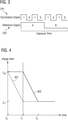
- FIG. 3 illustrates a reference signal 242 used for driving the photo-sensitive element 221 during the exposure time.
- the signal level of the reference signal 242 changes once during the exposure time such that only the first element with the modifiable first charge level is active while the signal level is high and that only the second element with the modifiable second charge level is active while the signal level is low. Accordingly, the charge carriers generated in the photo-sensitive element 221 by the light 202 received from the scene 201 during the exposure time accumulate at the first element while the signal level is high and accumulate at the second element while the signal level is low.
- the charge carriers generated in the photo-sensitive element 221 by the light 202 received from the scene 201 during the exposure time modify the first charge level for a first fraction of the exposure time (while the signal level of the reference signal 242 is high) and modify the second charge level for a second fraction of the exposure time (while the signal level of the reference signal 242 is low).
- the charge carriers generated in the photo-sensitive element 221 by the light 202 received from the scene 201 during the exposure time may increase or decrease the respective charge level.
- the charge levels of the first and the second element may be equal or different from each other at the beginning of the exposure time.
- the scene 201 is not illuminated by the ToF sensor 210 during the exposure time such that the light received 202 from the scene 201 comprises only ambient (background) light from the scene 201.
- the method 100 for the single exposure time of the at least one photo-sensitive element 221, additionally comprises determining 104 whether motion occurred in the scene during the exposure time based on a difference between the first charge level and the second charge level.
- the apparatus 200 comprises an accordingly configured processing circuit 250, which is coupled to the ToF sensor 210.
- the processing circuit 250 may be a single dedicated processor, a single shared processor, or a plurality of individual processors, some of which or all of which may be shared, a digital signal processor (DSP) hardware, an application specific integrated circuit (ASIC) or a field programmable gate array (FPGA).
- DSP digital signal processor
- ASIC application specific integrated circuit
- FPGA field programmable gate array
- the processing circuit 245 may optionally be coupled to, e.g., read only memory (ROM) for storing software, random access memory (RAM) and/or non-volatile memory.
- the processing circuit 250 is configured to determine whether motion occurred in the scene 201 during the exposure time based on a difference between the first charge level and the second charge level. For example, an output signal of the ToF sensor 210 may indicate the difference between the first charge level and the second charge level.
- the apparatus 200 may comprise further hardware - conventional and/or custom.
- Fig. 4 illustrates the temporal courses 401 and 402 of the charge levels of two elements with modifiable charge levels assuming that the scene is static, i.e. that no motion occurs in the scene during the exposure time.
- the exposure time starts at a time instant to and ends a time instant t 2 .
- the first charge level 401 of the first element is C 0 .
- the second charge level 402 of the second element is C 0 at the time instant to.
- the at least one photo-sensitive element 221 is driven such that the charge carriers generated in the photo-sensitive element 221 by the light 202 received from the scene 201 modify the first charge level 401 for a first fraction of the exposure time, which starts at the time instant to and ends at the time instant t 1 .
- the at least one photo-sensitive element 221 is driven such that the charge carriers generated in the photo-sensitive element 221 by the light 202 received from the scene 201 modify the second charge level 402 for a second fraction of the exposure time, which starts at the time instant t 1 and ends at the time instant t 2 .
- a duration of the first fraction of the exposure time is equal to a duration of the second fraction of the exposure time (time span from time instant t 1 to time instant t 2 ), i.e. the first fraction and the second fraction are equally long in time.
- the light 202 received from the scene 201 during the first fraction of the exposure time is substantially equal to the light 202 received from the scene 201 during the second fraction of the exposure time. Accordingly, the charge carriers are generated equally in the photo-sensitive element 221 during first fraction of the exposure time and the second fraction of the exposure time.
- the first charge level 401 and the second charge level 402 are equally modified by the charge carriers generated in the photo-sensitive element 221 by the light 202 received from the scene 201.
- the first charge level 401 and the second charge level 402 are equally decreased by the charge carriers generated in the photo-sensitive element 221 by the light 202 received from the scene 201.
- the first charge level 401 of the first element is C 1 at the time instant t 2 (as the first charge level 401 is no longer modified by the generated charge carriers after the time instant t 1 ).
- the second charge level 402 of the second element is C 1 at the time instant t 2 .
- the difference between the first charge level 401 and the second charge level 402 at the end of the exposure time is zero.
- Fig. 5 illustrates the temporal courses 501 and 502 of the charge levels of the two elements assuming that the scene is dynamic, i.e. that motion occurs in the scene during the exposure time.
- each of the first charge level 501 of the first element and the second charge level 502 of the second element is C 0 at the time instant to.
- the at least one photo-sensitive element 221 is driven such that the charge carriers generated in the photo-sensitive element 221 by the light 202 received from the scene 201 modify the first charge level 501 for a first fraction of the exposure time, which starts at the time instant to and ends at the time instant t 1 .
- the at least one photo-sensitive element 221 is driven such that the charge carriers generated in the photo-sensitive element 221 by the light 202 received from the scene 201 modify the second charge level 502 for a second fraction of the exposure time, which starts at the time instant t 1 and ends at the time instant t 2 .
- a duration of the first fraction of the exposure time (time span from time instant to to time instant t 1 ) is equal to a duration of the second fraction of the exposure time (time span from time instant t 1 to time instant t 2 ).
- the first charge level 501 is modified during the first fraction of the exposure time (from the time instant to to the time instant t 1 ) similar to what is described above for the first charge level 401 in the example of Fig. 4 .
- the first charge level 501 of the first element is again C 1 at the time instant t 2 (as the first charge level 501 is no longer modified by the generated charge carriers after the time instant t 1 ).
- the second charge level 502 is modified during the second fraction of the exposure time (from the time instant t 1 to the time instant t 2 ).
- No motion occurs in the scene 201 at the beginning of the second fraction of the exposure time.
- motion occurs in the scene 201 at a time instant t 3 during the second fraction of the exposure time.
- the light 202 received from the scene 201 from the time instant t 1 to the time instant t 3 is different from the light 202 received from the scene 201 from the time instant t 3 to the time instant t 2 . Therefore, the amount of charge carriers generated in the at least one photo-sensitive element 221 per unit time is different between the time span from the time instant t 1 to the time instant t 3 and the time span from the time instant t 3 to the time instant t 2 .
- the second charge level 502 is modified differently by the charge carriers generated in the photo-sensitive element 221 by the light 202 received from the scene 201 for the time span from the time instant t 1 to the time instant t 3 and charge carriers generated in the photo-sensitive element 221 for the time span from the time instant t 3 to the time instant t 2 .
- the second charge level 502 of the second element is therefore C 2 at the time instant t 2 .
- the first charge level 501 and the second charge level 502 are modified differently by the charge carriers generated in the photo-sensitive element 221 by the light 202 received from the scene 201 during the exposure time due to the motion at the time instant t 3 .
- the first charge level 501 and the second charge level 502 are decreased differently by the charge carriers generated in the photo-sensitive element 221 by the light 202 received from the scene 201 due to the motion at the time instant t 3 . Therefore, the first charge level 501 and the second charge level 502 differ by a charge difference ⁇ C at the end of the exposure time.
- the proposed method 100 may allow to determine whether motion occurred in a sensed scene using only a single exposure time, i.e. a single image. Accordingly, motion detection at a higher frame and with reduced power consumption may be enabled by the proposed technique.
- the voltage difference between the two capacitors may be measured as the voltage difference indicates the difference of the charge levels of the two capacitors. If the scene is static during the exposure, the readout of both capacitors is the same. If there is movement in the scene (in any dimension), the capacitors are discharged differently and the voltage of the one capacitor will not be the same as the voltage of the other capacitor.
- the difference between the first charge level 401 and the second charge level 402 (at the end of the exposure time) may not differ from a predefined value such as zero.
- it may be determined that no motion occurred in the scene 201 during the exposure time if the difference between the first charge level 401 and the second charge level 402 (at the end of the exposure time) differs from a predefined value such as zero by less than a threshold value.
- the threshold value may allow to compensate for noise as the first charge level 401 and the second charge level 402 may slightly vary at the end of the exposure time due to the noise.
- the threshold value may allow to compensate for noise as the first charge level 501 and the second charge level 502 may slightly vary due to the noise.
- A denotes the first charge level and B denotes the second charge level.
- a single image may be used for the motion detection enabling high frame rates for motion tracking applications.
- the predefined value to which the difference between the charge levels is compared need not be zero.
- the predefined value may be zero in case the first fraction of the exposure time is equally long as the second fraction of the exposure time as described above.
- the first fraction of the exposure time may be different from the second fraction of the exposure time.
- the first fraction of the exposure time may be greater or smaller than the second fraction of the exposure time. Accordingly, even though there occurs no motion in the scene 201 during the exposure time, the first charge level will be different from the second charge level due to the different fractions of the exposure time used for modifying the first charge level and the second charge level. Therefore, an according predefined value which is non-zero may be defined for motion detection.
- the first charge level and the second level may be different from each other at the beginning of the exposure time. Accordingly, the predefined value may be non-zero to account for the different charge levels at the beginning of the exposure time.
- the method 100 may additionally comprise applying a respective correction to at least one of the first charge level and the second charge level prior to determining the difference between the first charge level and the second charge level. Accordingly, errors of the ToF measurement or different fractions of the exposure time used for modifying the first charge level and the second charge level may be compensated. For example, at least one of the first charge level and the second charge level may be scaled in order to compensate for different fractions of the exposure time used for modifying the first charge level and the second charge level.
- the scene 201 is not illuminated by the ToF sensor 210 during the exposure time in some examples such that the light 202 received from the scene 201 comprises only ambient light.
- the illumination element 230 is not used in this example, the power consumption may be reduced.
- the exposure time may be scaled.
- the method 100 may comprise adjusting the exposure time based on an expected maximum motion or an expected motion speed in the scene. Accordingly, a Signal-to-Noise Ration (SNR) and the frame rate may be adjusted.
- SNR Signal-to-Noise Ration
- the scene need not be illuminated in the method 100 by the ToF sensor 210 during the exposure time such that the light 202 received from the scene 201 comprises only ambient light.
- the illumination element 230 may be activated subsequently for improved tracking.
- the method 100 may, for a single further (second) exposure time of the photo-sensitive element 221, further comprise illuminating the scene 201 with the light 203 such that the light 202 received from the scene 201 during the further exposure time comprises reflections of the emitted light 203 from the scene.
- the method 100 may further comprise driving the at least one photo-sensitive element 221 of the light capturing element 220 during the further exposure time such that charge carriers generated in the photo-sensitive element 221 by the light 202 received from the scene 201 during the further exposure time modify the first charge level for a first fraction of the further exposure time and modify the second charge level for a second fraction of the further exposure time.
- determining whether motion occurred in the scene during the further exposure time may be based on a difference between the first charge level and the second charge level obtained for the further exposure time. Accordingly, hybrid passive and active tracking may be enabled.
- the illumination element 220 is only activated if motion occurs. Accordingly, power consumption may be reduced.
- the detection of motion may be used to trigger the capture of depth or grayscale images.
- the method 100 may further comprise performing one or more ToF measurements using the at least one photo-sensitive element 221 for obtaining at least one of a depth image and a grey-scale image of at least part of the scene 201 (for example one or more continuous wave and/or one or more coded modulation measurements may be performed).
- the amount of motion may be determined additionally.
- the method 100 may further comprise determining an amount of motion in the scene 201 during the exposure time based on the difference between the first charge level and the second charge level.
- the amount of motion in the scene 201 during the exposure time may, e.g., be determined by comparing the difference between the first charge level and the second charge level to at least one motion threshold value related to a respective amount of motion.
- the change in charge level is an indication for motion such that stronger changes in charge levels allow to predict faster motion(s) in the scene.
- the combined photo-sensitive elements or pixels may be compared to a motion threshold value.
- determining the amount of motion in the scene during the exposure time may comprise determining a combined difference (value) based on the differences between the first charge level and the second charge level for the plurality of photo-sensitive elements.
- the combined difference (value) may be an average or a sum of the differences between the first charge level and the second charge level for the plurality of photo-sensitive elements.
- the amount of motion in the scene 201 during the exposure time may then be determined by comparing the combined difference (value) to at least one motion threshold value related to a respective amount of motion.
- an output signal of the ToF sensor 210 may further indicate a sum of the first charge level and the second charge level.
- the sum of the charge levels may be used for determining a greyscale image of the scene 201.
- the method 100 may, for the single exposure of the photo-sensitive element 221, comprise determining a greyscale image for at least part of the scene 201 based on the sum of the first charge level and the second charge level.
- the proposed technique for motion detection may be used for various applications.
- the ToF sensor 210 may be used in a motion tracking mode as described above at high travel speed (e.g. as a substitute for event based imagers) and as a depth sensor at low speed (e.g. for parking assistance or lane detection).
- the proposed technique further relates to a method for a vehicle comprising a ToF sensor.
- the method comprises using the ToF sensor for performing the method for detecting motion as proposed herein while a speed of the autonomous vehicle is in a first speed range for detecting motion in an environment of the autonomous vehicle.
- the method comprises using the ToF sensor for determining a distance to at least one object in the environment of the autonomous vehicle while the speed of the autonomous vehicle is in a second speed range. For example, a maximum speed in the second speed range is lower than a minimum speed in the first speed range.
- the proposed technique also relates to a vehicle comprising ToF sensor, wherein the vehicle is adapted to perform the above method for the vehicle.
- the proposed technique is not limited thereto.
- the propose technique for motion detection may, e.g., be used for sleep monitoring, infant monitoring, surveillance or as power saving mode for motion sensing as well.
- the examples as described herein may be summarized as follows: Some examples relate to a method for detecting motion in a scene using a ToF sensor.
- the ToF sensor comprises at least one photo-sensitive element comprising at least a first element with a modifiable first charge level and a second element with a modifiable second charge level.
- the method comprises for a single exposure time of the photo-sensitive element driving the at least one photo-sensitive element during the exposure time such that charge carriers generated in the photo-sensitive element by light received from the scene during the exposure time modify the first charge level for a first fraction of the exposure time and modify the second charge level for a second fraction of the exposure time.
- the method comprises determining whether motion occurred in the scene during the exposure time based on a difference between the first charge level and the second charge level.
- a duration of the first fraction of the exposure time is equal to a duration of the second fraction of the exposure time.
- the method further comprises applying a respective correction to at least one of the first charge level and the second charge level prior to determining the difference between the first charge level and the second charge level.
- an output signal of the ToF sensor indicates the difference between the first charge level and the second charge level.
- the method further comprises for the single exposure time of the photo-sensitive element: illuminating the scene with light such that the light received from the scene comprises reflections of the light from the scene.
- the scene is not illuminated by the ToF sensor during the exposure time such that the light received from the scene comprises only ambient light.
- the method further comprises for a single further exposure time of the photo-sensitive element: illuminating the scene with light; driving the at least one photo-sensitive element during the further exposure time such that charge carriers generated in the photo-sensitive element by light received from the scene during the further exposure time modify the first charge level for a first fraction of the further exposure time and modify the second charge level for a second fraction of the further exposure time; and determining whether motion occurred in the scene during the further exposure time based on a difference between the first charge level and the second charge level.
- the method further comprises: performing one or more ToF measurements using the at least one photo-sensitive element for obtaining at least one of a depth image and a grey-scale image of at least part of the scene.
- the method further comprises: determining an amount of motion in the scene during the exposure time based on the difference between the first charge level and the second charge level.
- determining the amount of motion in the scene during the exposure time comprises: comparing the difference between the first charge level and the second charge level to at least one motion threshold value related to a respective amount of motion.
- the ToF sensor comprises a plurality of photo-sensitive elements each comprising at least the first element and the second element, wherein determining the amount of motion in the scene during the exposure time comprises: determining an combined difference based on the differences between the first charge level and the second charge level for the plurality of photo-sensitive elements; and comparing the combined difference to at least one motion threshold value related to a respective amount of motion.
- the method further comprises for the single exposure of the photo-sensitive element: determining a greyscale image for at least part of the scene based on a sum of the first charge level and the second charge level.
- the method further comprises: adjusting the exposure time based on an expected maximum motion or an expected motion speed in the scene.
- the photo-sensitive element is a photonic mixer device.
- the apparatus comprises a ToF sensor comprising at least one photo-sensitive element comprising at least a first element with a modifiable first charge level and a second element with a modifiable second charge level. Further, the ToF sensor comprises driver circuitry configured to drive the at least one photo-sensitive element during a single exposure time of the photo-sensitive element such that charge carriers generated in the photo-sensitive element by light received from the scene during the exposure time modify the first charge level for a first fraction of the exposure time and modify the second charge level for a second fraction of the exposure time. The apparatus additionally comprises a processing circuit configured to determine whether motion occurred in the scene during the exposure time based on a difference between the first charge level and the second charge level.
- Further examples relate to a method for a vehicle comprising a ToF sensor.
- the method comprises using the ToF sensor for performing the method for detecting motion as proposed herein while a speed of the autonomous vehicle is in a first speed range for detecting motion in an environment of the autonomous vehicle. Further, the method comprises using the ToF sensor for determining a distance to at least one object in the environment of the autonomous vehicle while the speed of the autonomous vehicle is in a second speed range.
- a maximum speed in the second speed range is lower than a minimum speed in the first speed range.
- Still further examples relate to a vehicle comprising ToF sensor, wherein the vehicle is adapted to perform the proposed method for a vehicle.
- Examples of the present disclosure may enable active and passive motion detection with ToF sensors.
- examples of the present disclosure may enable detecting scene movement with a ToF camera using a single image.
- the proposed technique may enable to output motion data or trigger depth image capture.
- aspects described in relation to a device or system should also be understood as a description of the corresponding method.
- a block, device or functional aspect of the device or system may correspond to a feature, such as a method step, of the corresponding method.
- aspects described in relation to a method shall also be understood as a description of a corresponding block, a corresponding element, a property or a functional feature of a corresponding device or a corresponding system.
Landscapes
- Physics & Mathematics (AREA)
- Engineering & Computer Science (AREA)
- Electromagnetism (AREA)
- Computer Networks & Wireless Communication (AREA)
- General Physics & Mathematics (AREA)
- Radar, Positioning & Navigation (AREA)
- Remote Sensing (AREA)
- Multimedia (AREA)
- Signal Processing (AREA)
- Transforming Light Signals Into Electric Signals (AREA)
- Studio Devices (AREA)
Abstract
Description
- The present disclosure relates to motion detection. In particular, examples relate to a method and an apparatus for detecting motion in a scene using a Time-of-Flight (ToF) sensor.
- The detection of motion in a sensed scene may be beneficial for various purposes. For example, the detection of motion may be used for adjusting a frame rate used for capturing the scene or directly for generating optical flow data for gesture recognition and autonomous driving.
- A variety of sensors such as high-speed cameras, event-based imagers or ToF sensors for capturing motion in a scene exist. A conventional ToF sensor needs to take at least two images to detect motion in the sensed scene. A reduction of the number of images is beneficial as higher framerates are possible and less power is required.
- Hence, there may be a demand for improved motion detection using ToF sensing.
- The demand may be satisfied by the subject matter of the appended claims.
- An example relates to a method for detecting motion in a scene using a ToF sensor. The ToF sensor comprises at least one photo-sensitive element comprising at least a first element with a modifiable first charge level and a second element with a modifiable second charge level. The method comprises for a single exposure time of the photo-sensitive element driving the at least one photo-sensitive element during the exposure time such that charge carriers generated in the photo-sensitive element by light received from the scene during the exposure time modify the first charge level for a first fraction of the exposure time and modify the second charge level for a second fraction of the exposure time. Further, the method comprises determining whether motion occurred in the scene during the exposure time based on a difference between the first charge level and the second charge level.
- Another example relates to an apparatus for detecting motion in a scene. The apparatus comprises a ToF sensor comprising at least one photo-sensitive element comprising at least a first element with a modifiable first charge level and a second element with a modifiable second charge level. Further, the ToF sensor comprises driver circuitry configured to drive the at least one photo-sensitive element during a single exposure time of the photo-sensitive element such that charge carriers generated in the photo-sensitive element by light received from the scene during the exposure time modify the first charge level for a first fraction of the exposure time and modify the second charge level for a second fraction of the exposure time. The apparatus additionally comprises a processing circuit configured to determine whether motion occurred in the scene during the exposure time based on a difference between the first charge level and the second charge level.
- Some examples of apparatuses and/or methods will be described in the following by way of example only, and with reference to the accompanying figures, in which
-
Fig. 1 illustrates a flowchart of an example of a method for detecting motion in a scene; and -
Fig. 2 illustrates an example of an apparatus for detecting motion in a scene; -
Fig. 3 illustrates an example of an illumination and a reference signal; -
Fig. 4 illustrates exemplary courses of a first and a second charge level; and -
Fig. 5 illustrates other exemplary courses of a first and a second charge level. - Some examples are now described in more detail with reference to the enclosed figures. However, other possible examples are not limited to the features of these embodiments described in detail. Other examples may include modifications of the features as well as equivalents and alternatives to the features. Furthermore, the terminology used herein to describe certain examples should not be restrictive of further possible examples.
- Throughout the description of the figures same or similar reference numerals refer to same or similar elements and/or features, which may be identical or implemented in a modified form while providing the same or a similar function. The thickness of lines, layers and/or areas in the figures may also be exaggerated for clarification.
- When two elements A and B are combined using an 'or', this is to be understood as disclosing all possible combinations, i.e. only A, only B as well as A and B, unless expressly defined otherwise in the individual case. As an alternative wording for the same combinations, "at least one of A and B" or "A and/or B" may be used. This applies equivalently to combinations of more than two elements.
- If a singular form, such as "a", "an" and "the" is used and the use of only a single element is not defined as mandatory either explicitly or implicitly, further examples may also use several elements to implement the same function. If a function is described below as implemented using multiple elements, further examples may implement the same function using a single element or a single processing entity. It is further understood that the terms "include", "including", "comprise" and/or "comprising", when used, describe the presence of the specified features, integers, steps, operations, processes, elements, components and/or a group thereof, but do not exclude the presence or addition of one or more other features, integers, steps, operations, processes, elements, components and/or a group thereof.
-
Fig. 1 illustrates a flowchart of an example of amethod 100 for detecting motion in a scene using a ToF sensor. Themethod 100 will be described in the following further with reference toFig. 2 which illustrates anexemplary apparatus 200 for detecting motion in ascene 201. - The
apparatus 200 comprises aToF sensor 210. The ToFsensor 200 comprises anillumination element 230 for emittinglight 203 to thescene 201 and a light capturingelement 220 for capturinglight 202 received from thescene 201. Further, theToF sensor 210 comprisesdriver circuitry 240 for driving (controlling) theillumination element 230 and the light capturingelement 220. - The
illumination element 230 generates the (e.g. modulated)light 203. Theillumination element 230 may comprise any number of light sources. Theillumination element 230 may, e.g., comprise one or more Light-Emitting Diodes (LEDs) and/or one or more laser diodes (e.g. one or more Vertical-Cavity Surface-Emitting Lasers, VCSELs) which are fired based on one or more illumination signals provided by thedriver circuitry 240. - The light capturing
element 220 may comprise various components such as e.g. optics (e.g. one or more lenses) and electronic circuitry. In particular, the electronic circuitry comprises an image sensor comprising at least one photo-sensitive element or pixel 221 (e.g. comprising a Photonic Mixer Device, PMD, or a Charge-Coupled Device, CCD). For example, the image sensor may comprise a plurality of photo-sensitive elements or pixels. The at least one photo-sensitive element orpixel 221 may be driven based on one or more reference signals provided by thedriver circuitry 240. - The at least one photo-
sensitive element 221 comprises at least a first element with a modifiable first charge level and a second element with a modifiable second charge level. In some examples, the at least one photo-sensitive element 221 may comprise more than two elements with a respective modifiable charge level. The charge level of the respective element is modifiable by charge carriers generated in the photo-sensitive element 221 by thelight 202 received from thescene 201. The charge carriers may, e.g., be generated by thelight 202 based on the photoelectric effect. For example, the elements with the respective modifiable charge level may be capacitors or potential wells formed in a semiconductor material of the respective photo-sensitive element. - In the following, the
method 100 for detecting motion in thescene 201 will be described for a single exposure time of the at least one photo-sensitive element 221 of the light capturingelement 220. The single exposure time refers to a single continuous measuring operation for sensing thescene 201 during which the at least one photo-sensitive element 221 is active and exposed to thelight 202 arriving from thescene 201. In other words, the at least one photo-sensitive element 221 is exposed to thelight 202 arriving from thescene 201 and is actively measuring thelight 202 arriving from thescene 201 for the predefined continuous exposure time in order to sense thescene 201. It is to be noted that themethod 100 may be performed repeatedly. - For the single exposure time of the photo-
sensitive element 221, themethod 100 comprises driving 102 the at least one photo-sensitive element 221 during the exposure time such that charge carriers generated in the photo-sensitive element 221 by thelight 202 received from thescene 201 during the exposure time modify the first charge level for a first fraction of the exposure time and modify the second charge level for a second fraction of the exposure time. For example, thedriver circuitry 240 may drive the at least one photo-sensitive element 221 based on one or more reference signals such that charge carriers generated in the photo-sensitive element 221 by thelight 202 received from thescene 201 during the exposure time modify the first charge level for a first fraction of the exposure time and modify the second charge level for a second fraction of the exposure time. In case the at least one photo-sensitive element 221 comprises more than two elements with a respective modifiable charge level, thedrive circuitry 240 may drive them accordingly such that charge carriers generated in the photo-sensitive element 221 by thelight 202 received from thescene 201 during the exposure time modify the respective charge level of each of the elements for a respective (e.g. predefined) fraction of the exposure time. - This is exemplarily illustrated in
Fig. 3 for the case that the photo-sensitive element 221 comprises two elements with a respective modifiable charge level.Fig. 3 illustrates areference signal 242 used for driving the photo-sensitive element 221 during the exposure time. The signal level of thereference signal 242 changes once during the exposure time such that only the first element with the modifiable first charge level is active while the signal level is high and that only the second element with the modifiable second charge level is active while the signal level is low. Accordingly, the charge carriers generated in the photo-sensitive element 221 by the light 202 received from thescene 201 during the exposure time accumulate at the first element while the signal level is high and accumulate at the second element while the signal level is low. Therefore, the charge carriers generated in the photo-sensitive element 221 by the light 202 received from thescene 201 during the exposure time modify the first charge level for a first fraction of the exposure time (while the signal level of thereference signal 242 is high) and modify the second charge level for a second fraction of the exposure time (while the signal level of thereference signal 242 is low). For example, the charge carriers generated in the photo-sensitive element 221 by the light 202 received from thescene 201 during the exposure time may increase or decrease the respective charge level. The charge levels of the first and the second element may be equal or different from each other at the beginning of the exposure time. - Further illustrated in
Fig. 3 is anillumination signal 241 for driving theillumination element 230 during the exposure time in order to illuminate thescene 201 with the light 203 (e.g. modulated light) such that the light 202 received from thescene 201 comprises reflections of the emitted light 203 from the scene. However, it is to be noted that it is not necessary to actively illuminate thescene 201 during the exposure time. In other examples, thescene 201 is not illuminated by theToF sensor 210 during the exposure time such that the light received 202 from thescene 201 comprises only ambient (background) light from thescene 201. - Referring back to
Fig. 1 , themethod 100, for the single exposure time of the at least one photo-sensitive element 221, additionally comprises determining 104 whether motion occurred in the scene during the exposure time based on a difference between the first charge level and the second charge level. - The
apparatus 200 comprises an accordingly configuredprocessing circuit 250, which is coupled to theToF sensor 210. For example, theprocessing circuit 250 may be a single dedicated processor, a single shared processor, or a plurality of individual processors, some of which or all of which may be shared, a digital signal processor (DSP) hardware, an application specific integrated circuit (ASIC) or a field programmable gate array (FPGA). The processing circuit 245 may optionally be coupled to, e.g., read only memory (ROM) for storing software, random access memory (RAM) and/or non-volatile memory. Theprocessing circuit 250 is configured to determine whether motion occurred in thescene 201 during the exposure time based on a difference between the first charge level and the second charge level. For example, an output signal of theToF sensor 210 may indicate the difference between the first charge level and the second charge level. - The
apparatus 200 may comprise further hardware - conventional and/or custom. - How to determine whether motion occurred in the
scene 201 during the exposure time will be described in the following with respect toFigs. 4 and5 .Fig. 4 illustrates thetemporal courses - The exposure time starts at a time instant to and ends a time instant t2. At the time instant to, the
first charge level 401 of the first element is C0. Also thesecond charge level 402 of the second element is C0 at the time instant to. The at least one photo-sensitive element 221 is driven such that the charge carriers generated in the photo-sensitive element 221 by the light 202 received from thescene 201 modify thefirst charge level 401 for a first fraction of the exposure time, which starts at the time instant to and ends at the time instant t1. Further, the at least one photo-sensitive element 221 is driven such that the charge carriers generated in the photo-sensitive element 221 by the light 202 received from thescene 201 modify thesecond charge level 402 for a second fraction of the exposure time, which starts at the time instant t1 and ends at the time instant t2. - In the example of
Fig. 4 , a duration of the first fraction of the exposure time (time span from time instant to to time instant t1) is equal to a duration of the second fraction of the exposure time (time span from time instant t1 to time instant t2), i.e. the first fraction and the second fraction are equally long in time. As there is no motion in the scene, the light 202 received from thescene 201 during the first fraction of the exposure time is substantially equal to the light 202 received from thescene 201 during the second fraction of the exposure time. Accordingly, the charge carriers are generated equally in the photo-sensitive element 221 during first fraction of the exposure time and the second fraction of the exposure time. Therefore, thefirst charge level 401 and thesecond charge level 402 are equally modified by the charge carriers generated in the photo-sensitive element 221 by the light 202 received from thescene 201. In the example ofFig. 4 , thefirst charge level 401 and thesecond charge level 402 are equally decreased by the charge carriers generated in the photo-sensitive element 221 by the light 202 received from thescene 201. - Accordingly, the
first charge level 401 of the first element is C1 at the time instant t2 (as thefirst charge level 401 is no longer modified by the generated charge carriers after the time instant t1). Also thesecond charge level 402 of the second element is C1 at the time instant t2. Thus, the difference between thefirst charge level 401 and thesecond charge level 402 at the end of the exposure time is zero. - As a comparison,
Fig. 5 illustrates thetemporal courses - Again, each of the
first charge level 501 of the first element and thesecond charge level 502 of the second element is C0 at the time instant to. Analogously to what is described above forFig. 4 , the at least one photo-sensitive element 221 is driven such that the charge carriers generated in the photo-sensitive element 221 by the light 202 received from thescene 201 modify thefirst charge level 501 for a first fraction of the exposure time, which starts at the time instant to and ends at the time instant t1. Further, the at least one photo-sensitive element 221 is driven such that the charge carriers generated in the photo-sensitive element 221 by the light 202 received from thescene 201 modify thesecond charge level 502 for a second fraction of the exposure time, which starts at the time instant t1 and ends at the time instant t2. Again, a duration of the first fraction of the exposure time (time span from time instant to to time instant t1) is equal to a duration of the second fraction of the exposure time (time span from time instant t1 to time instant t2). - Initially, no motion occurs in the
scene 201 similar to the example ofFig. 4 . Therefore, thefirst charge level 501 is modified during the first fraction of the exposure time (from the time instant to to the time instant t1) similar to what is described above for thefirst charge level 401 in the example ofFig. 4 . As a consequence, thefirst charge level 501 of the first element is again C1 at the time instant t2 (as thefirst charge level 501 is no longer modified by the generated charge carriers after the time instant t1). - The
second charge level 502 is modified during the second fraction of the exposure time (from the time instant t1 to the time instant t2). No motion occurs in thescene 201 at the beginning of the second fraction of the exposure time. However, in contrast to the example ofFig. 4 , motion occurs in thescene 201 at a time instant t3 during the second fraction of the exposure time. As the scene is changed due to the motion/movement at the time instant t3, the light 202 received from thescene 201 from the time instant t1 to the time instant t3 is different from the light 202 received from thescene 201 from the time instant t3 to the time instant t2. Therefore, the amount of charge carriers generated in the at least one photo-sensitive element 221 per unit time is different between the time span from the time instant t1 to the time instant t3 and the time span from the time instant t3 to the time instant t2. - Accordingly, the
second charge level 502 is modified differently by the charge carriers generated in the photo-sensitive element 221 by the light 202 received from thescene 201 for the time span from the time instant t1 to the time instant t3 and charge carriers generated in the photo-sensitive element 221 for the time span from the time instant t3 to the time instant t2. Thesecond charge level 502 of the second element is therefore C2 at the time instant t2. - In other words, the
first charge level 501 and thesecond charge level 502 are modified differently by the charge carriers generated in the photo-sensitive element 221 by the light 202 received from thescene 201 during the exposure time due to the motion at the time instant t3. In the example ofFig. 5 , thefirst charge level 501 and thesecond charge level 502 are decreased differently by the charge carriers generated in the photo-sensitive element 221 by the light 202 received from thescene 201 due to the motion at the time instant t3. Therefore, thefirst charge level 501 and thesecond charge level 502 differ by a charge difference ΔC at the end of the exposure time. - When comparing the examples of
Fig. 4 andFig. 5 , it is evident that the difference between the first charge level and the second charge level at the end of the exposure time is indicative of whether motion occurred in a sensed scene during the exposure time. Compared to conventional ToF-based approaches using multiple images, the proposedmethod 100 may allow to determine whether motion occurred in a sensed scene using only a single exposure time, i.e. a single image. Accordingly, motion detection at a higher frame and with reduced power consumption may be enabled by the proposed technique. - If the photo-
sensitive element 221 separates generated charge carriers into, e.g., two capacitors which are discharged by the incoming light, the voltage difference between the two capacitors may be measured as the voltage difference indicates the difference of the charge levels of the two capacitors. If the scene is static during the exposure, the readout of both capacitors is the same. If there is movement in the scene (in any dimension), the capacitors are discharged differently and the voltage of the one capacitor will not be the same as the voltage of the other capacitor. - For example, referring to the example of
Fig. 4 , it may be determined that no motion occurred in thescene 201 during the exposure time if the difference between thefirst charge level 401 and the second charge level 402 (at the end of the exposure time) does not differ from a predefined value such as zero. Alternatively, it may be determined that no motion occurred in thescene 201 during the exposure time if the difference between thefirst charge level 401 and the second charge level 402 (at the end of the exposure time) differs from a predefined value such as zero by less than a threshold value. The threshold value may allow to compensate for noise as thefirst charge level 401 and thesecond charge level 402 may slightly vary at the end of the exposure time due to the noise. - For example, referring to the example of
Fig. 5 , it may be determined that motion occurred in thescene 201 during the exposure time if the difference between thefirst charge level 501 and the second charge level 502 (at the end of the exposure time) differs from a predefined value such as zero. Alternatively, it may be determined that motion occurred in thescene 201 during the exposure time if the difference between thefirst charge level 501 and the second charge level 502 (at the end of the exposure time) differs from a predefined value such as zero by more than a threshold value. Again, the threshold value may allow to compensate for noise as thefirst charge level 501 and thesecond charge level 502 may slightly vary due to the noise. - The determination whether motion occurred in the
scene 201 may be implemented as a post processing step. For example, a simple comparison may allow to detect movement:

- In mathematical expressions (1) and (2), A denotes the first charge level and B denotes the second charge level. Further, X = 1 denotes that that motion occurred and X = 0 denotes that no motion occurred. For example, a single image may be used for the motion detection enabling high frame rates for motion tracking applications.
- Further, it is to be noted that the predefined value to which the difference between the charge levels is compared need not be zero. The predefined value may be zero in case the first fraction of the exposure time is equally long as the second fraction of the exposure time as described above. However, in some examples, the first fraction of the exposure time may be different from the second fraction of the exposure time. For example, the first fraction of the exposure time may be greater or smaller than the second fraction of the exposure time. Accordingly, even though there occurs no motion in the
scene 201 during the exposure time, the first charge level will be different from the second charge level due to the different fractions of the exposure time used for modifying the first charge level and the second charge level. Therefore, an according predefined value which is non-zero may be defined for motion detection. Similarly, the first charge level and the second level may be different from each other at the beginning of the exposure time. Accordingly, the predefined value may be non-zero to account for the different charge levels at the beginning of the exposure time. - The
method 100 may additionally comprise applying a respective correction to at least one of the first charge level and the second charge level prior to determining the difference between the first charge level and the second charge level. Accordingly, errors of the ToF measurement or different fractions of the exposure time used for modifying the first charge level and the second charge level may be compensated. For example, at least one of the first charge level and the second charge level may be scaled in order to compensate for different fractions of the exposure time used for modifying the first charge level and the second charge level. - As described above, only the ambient light may be used for the detection of movement as the background infrared light of the
scene 201 may be sufficient for the motion detection. In other words, thescene 201 is not illuminated by theToF sensor 210 during the exposure time in some examples such that the light 202 received from thescene 201 comprises only ambient light. As theillumination element 230 is not used in this example, the power consumption may be reduced. - Further, the exposure time may be scaled. For example, the
method 100 may comprise adjusting the exposure time based on an expected maximum motion or an expected motion speed in the scene. Accordingly, a Signal-to-Noise Ration (SNR) and the frame rate may be adjusted. - As described above, the scene need not be illuminated in the
method 100 by theToF sensor 210 during the exposure time such that the light 202 received from thescene 201 comprises only ambient light. However, if a movement (i.e. motion) is detected, theillumination element 230 may be activated subsequently for improved tracking. Accordingly, if it is determined that motion occurred during the exposure time, themethod 100 may, for a single further (second) exposure time of the photo-sensitive element 221, further comprise illuminating thescene 201 with the light 203 such that the light 202 received from thescene 201 during the further exposure time comprises reflections of the emitted light 203 from the scene. Analogously to what is described above, themethod 100 may further comprise driving the at least one photo-sensitive element 221 of thelight capturing element 220 during the further exposure time such that charge carriers generated in the photo-sensitive element 221 by the light 202 received from thescene 201 during the further exposure time modify the first charge level for a first fraction of the further exposure time and modify the second charge level for a second fraction of the further exposure time. Again, determining whether motion occurred in the scene during the further exposure time may be based on a difference between the first charge level and the second charge level obtained for the further exposure time. Accordingly, hybrid passive and active tracking may be enabled. Theillumination element 220 is only activated if motion occurs. Accordingly, power consumption may be reduced. - Further, the detection of motion may be used to trigger the capture of depth or grayscale images. For example, if it is determined that motion occurred during the exposure time, the
method 100 may further comprise performing one or more ToF measurements using the at least one photo-sensitive element 221 for obtaining at least one of a depth image and a grey-scale image of at least part of the scene 201 (for example one or more continuous wave and/or one or more coded modulation measurements may be performed). - In other examples, the amount of motion may be determined additionally. For example, if it is determined that motion occurred during the exposure time, the
method 100 may further comprise determining an amount of motion in thescene 201 during the exposure time based on the difference between the first charge level and the second charge level. The amount of motion in thescene 201 during the exposure time may, e.g., be determined by comparing the difference between the first charge level and the second charge level to at least one motion threshold value related to a respective amount of motion. The change in charge level is an indication for motion such that stronger changes in charge levels allow to predict faster motion(s) in the scene. - Alternatively, the combined photo-sensitive elements or pixels may be compared to a motion threshold value. In other words, for a plurality of photo-sensitive elements each comprising at least the first element and the second element, determining the amount of motion in the scene during the exposure time may comprise determining a combined difference (value) based on the differences between the first charge level and the second charge level for the plurality of photo-sensitive elements. For example, the combined difference (value) may be an average or a sum of the differences between the first charge level and the second charge level for the plurality of photo-sensitive elements. The amount of motion in the
scene 201 during the exposure time may then be determined by comparing the combined difference (value) to at least one motion threshold value related to a respective amount of motion. - In some examples, an output signal of the
ToF sensor 210 may further indicate a sum of the first charge level and the second charge level. The sum of the charge levels may be used for determining a greyscale image of thescene 201. For example, themethod 100 may, for the single exposure of the photo-sensitive element 221, comprise determining a greyscale image for at least part of thescene 201 based on the sum of the first charge level and the second charge level. - The proposed technique for motion detection may be used for various applications. For example, in an automotive context, the
ToF sensor 210 may be used in a motion tracking mode as described above at high travel speed (e.g. as a substitute for event based imagers) and as a depth sensor at low speed (e.g. for parking assistance or lane detection). In other words, the proposed technique further relates to a method for a vehicle comprising a ToF sensor. The method comprises using the ToF sensor for performing the method for detecting motion as proposed herein while a speed of the autonomous vehicle is in a first speed range for detecting motion in an environment of the autonomous vehicle. Further, the method comprises using the ToF sensor for determining a distance to at least one object in the environment of the autonomous vehicle while the speed of the autonomous vehicle is in a second speed range. For example, a maximum speed in the second speed range is lower than a minimum speed in the first speed range. - Accordingly, the proposed technique also relates to a vehicle comprising ToF sensor, wherein the vehicle is adapted to perform the above method for the vehicle.
- However, it is to be noted that the proposed technique is not limited thereto. The propose technique for motion detection may, e.g., be used for sleep monitoring, infant monitoring, surveillance or as power saving mode for motion sensing as well.
- The examples as described herein may be summarized as follows:
Some examples relate to a method for detecting motion in a scene using a ToF sensor. The ToF sensor comprises at least one photo-sensitive element comprising at least a first element with a modifiable first charge level and a second element with a modifiable second charge level. The method comprises for a single exposure time of the photo-sensitive element driving the at least one photo-sensitive element during the exposure time such that charge carriers generated in the photo-sensitive element by light received from the scene during the exposure time modify the first charge level for a first fraction of the exposure time and modify the second charge level for a second fraction of the exposure time. Further, the method comprises determining whether motion occurred in the scene during the exposure time based on a difference between the first charge level and the second charge level. - According to some examples, it is determined that no motion occurred in the scene if the difference between the first charge level and the second charge level does not differ from a predefined value or if the difference between the first charge level and the second charge level differs from the predefined value by less than a threshold value.
- In some examples, it is determined that motion occurred in the scene if the difference between the first charge level and the second charge level differs from a predefined value or if the difference between the first charge level and the second charge level differs from the predefined value by more than a threshold value.
- According to some examples, a duration of the first fraction of the exposure time is equal to a duration of the second fraction of the exposure time.
- In some examples, the method further comprises applying a respective correction to at least one of the first charge level and the second charge level prior to determining the difference between the first charge level and the second charge level.
- According to some examples, an output signal of the ToF sensor indicates the difference between the first charge level and the second charge level.
- In some examples, the method further comprises for the single exposure time of the photo-sensitive element: illuminating the scene with light such that the light received from the scene comprises reflections of the light from the scene.
- In alternative examples, the scene is not illuminated by the ToF sensor during the exposure time such that the light received from the scene comprises only ambient light.
- According to some examples, if it is determined that motion occurred during the exposure time, the method further comprises for a single further exposure time of the photo-sensitive element: illuminating the scene with light; driving the at least one photo-sensitive element during the further exposure time such that charge carriers generated in the photo-sensitive element by light received from the scene during the further exposure time modify the first charge level for a first fraction of the further exposure time and modify the second charge level for a second fraction of the further exposure time; and determining whether motion occurred in the scene during the further exposure time based on a difference between the first charge level and the second charge level.
- In some examples, if it is determined that motion occurred during the exposure time, the method further comprises: performing one or more ToF measurements using the at least one photo-sensitive element for obtaining at least one of a depth image and a grey-scale image of at least part of the scene.
- According to some examples, if it is determined that motion occurred during the exposure time, the method further comprises: determining an amount of motion in the scene during the exposure time based on the difference between the first charge level and the second charge level.
- In some examples, determining the amount of motion in the scene during the exposure time comprises: comparing the difference between the first charge level and the second charge level to at least one motion threshold value related to a respective amount of motion.
- In alternative examples, the ToF sensor comprises a plurality of photo-sensitive elements each comprising at least the first element and the second element, wherein determining the amount of motion in the scene during the exposure time comprises: determining an combined difference based on the differences between the first charge level and the second charge level for the plurality of photo-sensitive elements; and comparing the combined difference to at least one motion threshold value related to a respective amount of motion.
- According to some examples, the method further comprises for the single exposure of the photo-sensitive element: determining a greyscale image for at least part of the scene based on a sum of the first charge level and the second charge level.
- In some examples, the method further comprises: adjusting the exposure time based on an expected maximum motion or an expected motion speed in the scene.
- According to some examples, the photo-sensitive element is a photonic mixer device.
- Other examples relate to an apparatus for detecting motion in a scene. The apparatus comprises a ToF sensor comprising at least one photo-sensitive element comprising at least a first element with a modifiable first charge level and a second element with a modifiable second charge level. Further, the ToF sensor comprises driver circuitry configured to drive the at least one photo-sensitive element during a single exposure time of the photo-sensitive element such that charge carriers generated in the photo-sensitive element by light received from the scene during the exposure time modify the first charge level for a first fraction of the exposure time and modify the second charge level for a second fraction of the exposure time. The apparatus additionally comprises a processing circuit configured to determine whether motion occurred in the scene during the exposure time based on a difference between the first charge level and the second charge level.
- Further examples relate to a method for a vehicle comprising a ToF sensor. The method comprises using the ToF sensor for performing the method for detecting motion as proposed herein while a speed of the autonomous vehicle is in a first speed range for detecting motion in an environment of the autonomous vehicle. Further, the method comprises using the ToF sensor for determining a distance to at least one object in the environment of the autonomous vehicle while the speed of the autonomous vehicle is in a second speed range.
- In some examples, a maximum speed in the second speed range is lower than a minimum speed in the first speed range.
- Still further examples relate to a vehicle comprising ToF sensor, wherein the vehicle is adapted to perform the proposed method for a vehicle.
- Examples of the present disclosure may enable active and passive motion detection with ToF sensors. In particular, examples of the present disclosure may enable detecting scene movement with a ToF camera using a single image. The proposed technique may enable to output motion data or trigger depth image capture.
- The aspects and features described in relation to a particular one of the previous examples may also be combined with one or more of the further examples to replace an identical or similar feature of that further example or to additionally introduce the features into the further example.
- It is further understood that the disclosure of several steps, processes, operations or functions disclosed in the description or claims shall not be construed to imply that these operations are necessarily dependent on the order described, unless explicitly stated in the individual case or necessary for technical reasons. Therefore, the previous description does not limit the execution of several steps or functions to a certain order. Furthermore, in further examples, a single step, function, process or operation may include and/or be broken up into several sub-steps, -functions, -processes or -operations.
- If some aspects have been described in relation to a device or system, these aspects should also be understood as a description of the corresponding method. For example, a block, device or functional aspect of the device or system may correspond to a feature, such as a method step, of the corresponding method. Accordingly, aspects described in relation to a method shall also be understood as a description of a corresponding block, a corresponding element, a property or a functional feature of a corresponding device or a corresponding system.
- The following claims are hereby incorporated in the detailed description, wherein each claim may stand on its own as a separate example. It should also be noted that although in the claims a dependent claim refers to a particular combination with one or more other claims, other examples may also include a combination of the dependent claim with the subject matter of any other dependent or independent claim. Such combinations are hereby explicitly proposed, unless it is stated in the individual case that a particular combination is not intended. Furthermore, features of a claim should also be included for any other independent claim, even if that claim is not directly defined as dependent on that other independent claim.
Claims (15)
- A method (100) for detecting motion in a scene using a time-of-flight sensor, wherein the time-of-flight sensor comprises at least one photo-sensitive element comprising at least a first element with a modifiable first charge level and a second element with a modifiable second charge level, the method comprising for a single exposure time of the photo-sensitive element:driving (102) the at least one photo-sensitive element during the exposure time such that charge carriers generated in the photo-sensitive element by light received from the scene during the exposure time modify the first charge level for a first fraction of the exposure time and modify the second charge level for a second fraction of the exposure time;determining (104) whether motion occurred in the scene during the exposure time based on a difference between the first charge level and the second charge level.
- The method (100) of claim 1, wherein it is determined that no motion occurred in the scene if the difference between the first charge level and the second charge level does not differ from a predefined value or if the difference between the first charge level and the second charge level differs from the predefined value by less than a threshold value.
- The method (100) of claim 1 or claim 2, wherein it is determined that motion occurred in the scene if the difference between the first charge level and the second charge level differs from a predefined value or if the difference between the first charge level and the second charge level differs from the predefined value by more than a threshold value.
- The method (100) of any of claims 1 to 3, wherein a duration of the first fraction of the exposure time is equal to a duration of the second fraction of the exposure time.
- The method (100) of any of claims 1 to 4, further comprising applying a respective correction to at least one of the first charge level and the second charge level prior to determining the difference between the first charge level and the second charge level.
- The method (100) of any of claims 1 to 5, wherein an output signal of the time-of-flight sensor indicates the difference between the first charge level and the second charge level.
- The method (100) of any of claims 1 to 6, further comprising for the single exposure time of the photo-sensitive element:
illuminating the scene with light such that the light received from the scene comprises reflections of the light from the scene. - The method (100) of any of claims 1 to 6, wherein the scene is not illuminated by the time-of-flight sensor during the exposure time such that the light received from the scene comprises only ambient light.
- The method (100) of claim 8, wherein, if it is determined that motion occurred during the exposure time, the method further comprises for a single further exposure time of the photo-sensitive element:illuminating the scene with light;driving the at least one photo-sensitive element during the further exposure time such that charge carriers generated in the photo-sensitive element by light received from the scene during the further exposure time modify the first charge level for a first fraction of the further exposure time and modify the second charge level for a second fraction of the further exposure time; anddetermining whether motion occurred in the scene during the further exposure time based on a difference between the first charge level and the second charge level.
- The method (100) of any of claims 1 to 8, wherein, if it is determined that motion occurred during the exposure time, the method further comprises:
performing one or more time-of-flight measurements using the at least one photo-sensitive element for obtaining at least one of a depth image and a grey-scale image of at least part of the scene. - The method (100) of any of claims 1 to 10, wherein, if it is determined that motion occurred during the exposure time, the method further comprises:
determining an amount of motion in the scene during the exposure time based on the difference between the first charge level and the second charge level. - The method (100) of claim 11, wherein determining the amount of motion in the scene during the exposure time comprises:
comparing the difference between the first charge level and the second charge level to at least one motion threshold value related to a respective amount of motion. - The method (100) of claim 11, wherein the time-of-flight sensor comprises a plurality of photo-sensitive elements each comprising at least the first element and the second element, and wherein determining the amount of motion in the scene during the exposure time comprises:determining a combined difference based on the differences between the first charge level and the second charge level for the plurality of photo-sensitive elements; andcomparing the combined difference to at least one motion threshold value related to a respective amount of motion.
- The method (100) of any of claims 1 to 13, further comprising for the single exposure of the photo-sensitive element:
determining a greyscale image for at least part of the scene based on a sum of the first charge level and the second charge level. - An apparatus (200) for detecting motion in a scene (201), comprising:a time-of-flight sensor (210) comprising:at least one photo-sensitive element (221) comprising at least a first element with a modifiable first charge level and a second element with a modifiable second charge level; anddriver circuitry (240) configured to drive the at least one photo-sensitive element (221) during a single exposure time of the photo-sensitive element (221) such that charge carriers generated in the photo-sensitive element (221) by light (203) received from the scene (201) during the exposure time modify the first charge level for a first fraction of the exposure time and modify the second charge level for a second fraction of the exposure time; anda processing circuit (250) configured to determine whether motion occurred in the scene (201) during the exposure time based on a difference between the first charge level and the second charge level.
Priority Applications (1)
| Application Number | Priority Date | Filing Date | Title |
|---|---|---|---|
| EP20194271.1A EP3964862B1 (en) | 2020-09-03 | 2020-09-03 | Method and apparatus for detecting motion in a scene using a time-of-flight sensor |
Applications Claiming Priority (1)
| Application Number | Priority Date | Filing Date | Title |
|---|---|---|---|
| EP20194271.1A EP3964862B1 (en) | 2020-09-03 | 2020-09-03 | Method and apparatus for detecting motion in a scene using a time-of-flight sensor |
Publications (2)
| Publication Number | Publication Date |
|---|---|
| EP3964862A1 true EP3964862A1 (en) | 2022-03-09 |
| EP3964862B1 EP3964862B1 (en) | 2024-05-01 |
Family
ID=72355848
Family Applications (1)
| Application Number | Title | Priority Date | Filing Date |
|---|---|---|---|
| EP20194271.1A Active EP3964862B1 (en) | 2020-09-03 | 2020-09-03 | Method and apparatus for detecting motion in a scene using a time-of-flight sensor |
Country Status (1)
| Country | Link |
|---|---|
| EP (1) | EP3964862B1 (en) |
Citations (2)
| Publication number | Priority date | Publication date | Assignee | Title |
|---|---|---|---|---|
| US20150338509A1 (en) * | 2012-12-17 | 2015-11-26 | Pmdtechnologies Gmbh | Time-of-flight camera with motion detection |
| EP2978216A1 (en) * | 2014-07-24 | 2016-01-27 | Espros Photonics AG | Image sensor |
-
2020
- 2020-09-03 EP EP20194271.1A patent/EP3964862B1/en active Active
Patent Citations (2)
| Publication number | Priority date | Publication date | Assignee | Title |
|---|---|---|---|---|
| US20150338509A1 (en) * | 2012-12-17 | 2015-11-26 | Pmdtechnologies Gmbh | Time-of-flight camera with motion detection |
| EP2978216A1 (en) * | 2014-07-24 | 2016-01-27 | Espros Photonics AG | Image sensor |
Also Published As
| Publication number | Publication date |
|---|---|
| EP3964862B1 (en) | 2024-05-01 |
Similar Documents
| Publication | Publication Date | Title |
|---|---|---|
| CN102016921B (en) | image processing device | |
| CN109903324B (en) | Depth image acquisition method and device | |
| US20210041539A1 (en) | Method and apparatus for determining malfunction, and sensor system | |
| CN110596727A (en) | Distance measuring device for outputting precision information | |
| US12504513B2 (en) | Object reflectivity estimation in a LIDAR system | |
| CN1257432C (en) | Phase difference detection method, phase difference detection apparatus, range finding apparatus and imaging apparatus | |
| JP3820087B2 (en) | 3D image detection device | |
| CN117015724A (en) | Time-of-flight demodulation circuit, time-of-flight demodulation method, time-of-flight imaging device, time-of-flight imaging device control method | |
| JP2021032762A (en) | Range-finding system and electronic instrument | |
| US20220099836A1 (en) | Method for measuring depth using a time-of-flight depth sensor | |
| WO2020066236A1 (en) | Depth acquisition device, depth acquisition method, and program | |
| CN113766143A (en) | Optical detection chip, image processing device and operation method thereof | |
| WO2021059698A1 (en) | Ranging device, method for controlling ranging device, and electronic apparatus | |
| EP3943977B1 (en) | Apparatus comprising a time-of-flight sensor and method for characterizing a time-of-flight sensor | |
| EP3964857A1 (en) | Method and apparatus for determining a reflectivity value indicating a reflectivity of an object | |
| US12439170B2 (en) | Object recognition system and method of signal processing performed by object recognition system, and electronic apparatus | |
| US20190156500A1 (en) | Distance measurement system applicable to different reflecting surfaces and computer system | |
| EP3964862B1 (en) | Method and apparatus for detecting motion in a scene using a time-of-flight sensor | |
| CN1250955C (en) | Phase difference detection methd, phase difference detector, distance finder and imaging appts. | |
| CN114599999B (en) | Movement amount estimation device, movement amount estimation method, movement amount estimation program, and movement amount estimation system | |
| EP4431869A1 (en) | Depth sensor device and method for operating a depth sensor device | |
| US12429594B2 (en) | Time-of-flight sensing using continuous wave and coded modulation measurements | |
| US20220390575A1 (en) | Method and apparatus for determining an intensity value representing an intensity of light reflected from an object in a scene | |
| KR20220165678A (en) | Apparatus for LIDAR | |
| US20230071101A1 (en) | Apparatus and method for sensing a scene |
Legal Events
| Date | Code | Title | Description |
|---|---|---|---|
| PUAI | Public reference made under article 153(3) epc to a published international application that has entered the european phase |
Free format text: ORIGINAL CODE: 0009012 |
|
| STAA | Information on the status of an ep patent application or granted ep patent |
Free format text: STATUS: THE APPLICATION HAS BEEN PUBLISHED |
|
| AK | Designated contracting states |
Kind code of ref document: A1 Designated state(s): AL AT BE BG CH CY CZ DE DK EE ES FI FR GB GR HR HU IE IS IT LI LT LU LV MC MK MT NL NO PL PT RO RS SE SI SK SM TR |
|
| STAA | Information on the status of an ep patent application or granted ep patent |
Free format text: STATUS: REQUEST FOR EXAMINATION WAS MADE |
|
| 17P | Request for examination filed |
Effective date: 20220805 |
|
| RBV | Designated contracting states (corrected) |
Designated state(s): AL AT BE BG CH CY CZ DE DK EE ES FI FR GB GR HR HU IE IS IT LI LT LU LV MC MK MT NL NO PL PT RO RS SE SI SK SM TR |
|
| GRAP | Despatch of communication of intention to grant a patent |
Free format text: ORIGINAL CODE: EPIDOSNIGR1 |
|
| RIC1 | Information provided on ipc code assigned before grant |
Ipc: H04N 23/70 20230101ALI20231115BHEP Ipc: G01S 17/50 20060101ALI20231115BHEP Ipc: G01S 7/487 20060101ALI20231115BHEP Ipc: G01S 7/4865 20200101AFI20231115BHEP |
|
| STAA | Information on the status of an ep patent application or granted ep patent |
Free format text: STATUS: GRANT OF PATENT IS INTENDED |
|
| INTG | Intention to grant announced |
Effective date: 20231221 |
|
| GRAS | Grant fee paid |
Free format text: ORIGINAL CODE: EPIDOSNIGR3 |
|
| GRAA | (expected) grant |
Free format text: ORIGINAL CODE: 0009210 |
|
| STAA | Information on the status of an ep patent application or granted ep patent |
Free format text: STATUS: THE PATENT HAS BEEN GRANTED |
|
| P01 | Opt-out of the competence of the unified patent court (upc) registered |
Effective date: 20240301 |
|
| AK | Designated contracting states |
Kind code of ref document: B1 Designated state(s): AL AT BE BG CH CY CZ DE DK EE ES FI FR GB GR HR HU IE IS IT LI LT LU LV MC MK MT NL NO PL PT RO RS SE SI SK SM TR |
|
| REG | Reference to a national code |
Ref country code: GB Ref legal event code: FG4D |
|
| REG | Reference to a national code |
Ref country code: CH Ref legal event code: EP |
|
| REG | Reference to a national code |
Ref country code: IE Ref legal event code: FG4D |
|
| REG | Reference to a national code |
Ref country code: DE Ref legal event code: R096 Ref document number: 602020029974 Country of ref document: DE |
|
| REG | Reference to a national code |
Ref country code: LT Ref legal event code: MG9D |
|
| REG | Reference to a national code |
Ref country code: NL Ref legal event code: MP Effective date: 20240501 |
|
| PG25 | Lapsed in a contracting state [announced via postgrant information from national office to epo] |
Ref country code: IS Free format text: LAPSE BECAUSE OF FAILURE TO SUBMIT A TRANSLATION OF THE DESCRIPTION OR TO PAY THE FEE WITHIN THE PRESCRIBED TIME-LIMIT Effective date: 20240901 |
|
| PG25 | Lapsed in a contracting state [announced via postgrant information from national office to epo] |
Ref country code: BG Free format text: LAPSE BECAUSE OF FAILURE TO SUBMIT A TRANSLATION OF THE DESCRIPTION OR TO PAY THE FEE WITHIN THE PRESCRIBED TIME-LIMIT Effective date: 20240501 |
|
| PG25 | Lapsed in a contracting state [announced via postgrant information from national office to epo] |
Ref country code: HR Free format text: LAPSE BECAUSE OF FAILURE TO SUBMIT A TRANSLATION OF THE DESCRIPTION OR TO PAY THE FEE WITHIN THE PRESCRIBED TIME-LIMIT Effective date: 20240501 Ref country code: FI Free format text: LAPSE BECAUSE OF FAILURE TO SUBMIT A TRANSLATION OF THE DESCRIPTION OR TO PAY THE FEE WITHIN THE PRESCRIBED TIME-LIMIT Effective date: 20240501 |
|
| PG25 | Lapsed in a contracting state [announced via postgrant information from national office to epo] |
Ref country code: GR Free format text: LAPSE BECAUSE OF FAILURE TO SUBMIT A TRANSLATION OF THE DESCRIPTION OR TO PAY THE FEE WITHIN THE PRESCRIBED TIME-LIMIT Effective date: 20240802 |
|
| PG25 | Lapsed in a contracting state [announced via postgrant information from national office to epo] |
Ref country code: PT Free format text: LAPSE BECAUSE OF FAILURE TO SUBMIT A TRANSLATION OF THE DESCRIPTION OR TO PAY THE FEE WITHIN THE PRESCRIBED TIME-LIMIT Effective date: 20240902 |
|
| REG | Reference to a national code |
Ref country code: AT Ref legal event code: MK05 Ref document number: 1683095 Country of ref document: AT Kind code of ref document: T Effective date: 20240501 |
|
| PG25 | Lapsed in a contracting state [announced via postgrant information from national office to epo] |
Ref country code: NL Free format text: LAPSE BECAUSE OF FAILURE TO SUBMIT A TRANSLATION OF THE DESCRIPTION OR TO PAY THE FEE WITHIN THE PRESCRIBED TIME-LIMIT Effective date: 20240501 |
|
| PG25 | Lapsed in a contracting state [announced via postgrant information from national office to epo] |
Ref country code: ES Free format text: LAPSE BECAUSE OF FAILURE TO SUBMIT A TRANSLATION OF THE DESCRIPTION OR TO PAY THE FEE WITHIN THE PRESCRIBED TIME-LIMIT Effective date: 20240501 |
|
| PG25 | Lapsed in a contracting state [announced via postgrant information from national office to epo] |
Ref country code: AT Free format text: LAPSE BECAUSE OF FAILURE TO SUBMIT A TRANSLATION OF THE DESCRIPTION OR TO PAY THE FEE WITHIN THE PRESCRIBED TIME-LIMIT Effective date: 20240501 |
|
| PG25 | Lapsed in a contracting state [announced via postgrant information from national office to epo] |
Ref country code: PL Free format text: LAPSE BECAUSE OF FAILURE TO SUBMIT A TRANSLATION OF THE DESCRIPTION OR TO PAY THE FEE WITHIN THE PRESCRIBED TIME-LIMIT Effective date: 20240501 |
|
| PG25 | Lapsed in a contracting state [announced via postgrant information from national office to epo] |
Ref country code: LV Free format text: LAPSE BECAUSE OF FAILURE TO SUBMIT A TRANSLATION OF THE DESCRIPTION OR TO PAY THE FEE WITHIN THE PRESCRIBED TIME-LIMIT Effective date: 20240501 |
|
| PG25 | Lapsed in a contracting state [announced via postgrant information from national office to epo] |
Ref country code: PT Free format text: LAPSE BECAUSE OF FAILURE TO SUBMIT A TRANSLATION OF THE DESCRIPTION OR TO PAY THE FEE WITHIN THE PRESCRIBED TIME-LIMIT Effective date: 20240902 Ref country code: PL Free format text: LAPSE BECAUSE OF FAILURE TO SUBMIT A TRANSLATION OF THE DESCRIPTION OR TO PAY THE FEE WITHIN THE PRESCRIBED TIME-LIMIT Effective date: 20240501 Ref country code: NO Free format text: LAPSE BECAUSE OF FAILURE TO SUBMIT A TRANSLATION OF THE DESCRIPTION OR TO PAY THE FEE WITHIN THE PRESCRIBED TIME-LIMIT Effective date: 20240801 Ref country code: NL Free format text: LAPSE BECAUSE OF FAILURE TO SUBMIT A TRANSLATION OF THE DESCRIPTION OR TO PAY THE FEE WITHIN THE PRESCRIBED TIME-LIMIT Effective date: 20240501 Ref country code: LV Free format text: LAPSE BECAUSE OF FAILURE TO SUBMIT A TRANSLATION OF THE DESCRIPTION OR TO PAY THE FEE WITHIN THE PRESCRIBED TIME-LIMIT Effective date: 20240501 Ref country code: IS Free format text: LAPSE BECAUSE OF FAILURE TO SUBMIT A TRANSLATION OF THE DESCRIPTION OR TO PAY THE FEE WITHIN THE PRESCRIBED TIME-LIMIT Effective date: 20240901 Ref country code: HR Free format text: LAPSE BECAUSE OF FAILURE TO SUBMIT A TRANSLATION OF THE DESCRIPTION OR TO PAY THE FEE WITHIN THE PRESCRIBED TIME-LIMIT Effective date: 20240501 Ref country code: GR Free format text: LAPSE BECAUSE OF FAILURE TO SUBMIT A TRANSLATION OF THE DESCRIPTION OR TO PAY THE FEE WITHIN THE PRESCRIBED TIME-LIMIT Effective date: 20240802 Ref country code: FI Free format text: LAPSE BECAUSE OF FAILURE TO SUBMIT A TRANSLATION OF THE DESCRIPTION OR TO PAY THE FEE WITHIN THE PRESCRIBED TIME-LIMIT Effective date: 20240501 Ref country code: ES Free format text: LAPSE BECAUSE OF FAILURE TO SUBMIT A TRANSLATION OF THE DESCRIPTION OR TO PAY THE FEE WITHIN THE PRESCRIBED TIME-LIMIT Effective date: 20240501 Ref country code: BG Free format text: LAPSE BECAUSE OF FAILURE TO SUBMIT A TRANSLATION OF THE DESCRIPTION OR TO PAY THE FEE WITHIN THE PRESCRIBED TIME-LIMIT Effective date: 20240501 Ref country code: AT Free format text: LAPSE BECAUSE OF FAILURE TO SUBMIT A TRANSLATION OF THE DESCRIPTION OR TO PAY THE FEE WITHIN THE PRESCRIBED TIME-LIMIT Effective date: 20240501 Ref country code: RS Free format text: LAPSE BECAUSE OF FAILURE TO SUBMIT A TRANSLATION OF THE DESCRIPTION OR TO PAY THE FEE WITHIN THE PRESCRIBED TIME-LIMIT Effective date: 20240801 |
|
| PG25 | Lapsed in a contracting state [announced via postgrant information from national office to epo] |
Ref country code: DK Free format text: LAPSE BECAUSE OF FAILURE TO SUBMIT A TRANSLATION OF THE DESCRIPTION OR TO PAY THE FEE WITHIN THE PRESCRIBED TIME-LIMIT Effective date: 20240501 |
|
| PG25 | Lapsed in a contracting state [announced via postgrant information from national office to epo] |
Ref country code: EE Free format text: LAPSE BECAUSE OF FAILURE TO SUBMIT A TRANSLATION OF THE DESCRIPTION OR TO PAY THE FEE WITHIN THE PRESCRIBED TIME-LIMIT Effective date: 20240501 |
|
| PG25 | Lapsed in a contracting state [announced via postgrant information from national office to epo] |
Ref country code: CZ Free format text: LAPSE BECAUSE OF FAILURE TO SUBMIT A TRANSLATION OF THE DESCRIPTION OR TO PAY THE FEE WITHIN THE PRESCRIBED TIME-LIMIT Effective date: 20240501 |
|
| PG25 | Lapsed in a contracting state [announced via postgrant information from national office to epo] |
Ref country code: RO Free format text: LAPSE BECAUSE OF FAILURE TO SUBMIT A TRANSLATION OF THE DESCRIPTION OR TO PAY THE FEE WITHIN THE PRESCRIBED TIME-LIMIT Effective date: 20240501 Ref country code: SK Free format text: LAPSE BECAUSE OF FAILURE TO SUBMIT A TRANSLATION OF THE DESCRIPTION OR TO PAY THE FEE WITHIN THE PRESCRIBED TIME-LIMIT Effective date: 20240501 |
|
| PG25 | Lapsed in a contracting state [announced via postgrant information from national office to epo] |
Ref country code: SM Free format text: LAPSE BECAUSE OF FAILURE TO SUBMIT A TRANSLATION OF THE DESCRIPTION OR TO PAY THE FEE WITHIN THE PRESCRIBED TIME-LIMIT Effective date: 20240501 |
|
| PG25 | Lapsed in a contracting state [announced via postgrant information from national office to epo] |
Ref country code: SM Free format text: LAPSE BECAUSE OF FAILURE TO SUBMIT A TRANSLATION OF THE DESCRIPTION OR TO PAY THE FEE WITHIN THE PRESCRIBED TIME-LIMIT Effective date: 20240501 Ref country code: SK Free format text: LAPSE BECAUSE OF FAILURE TO SUBMIT A TRANSLATION OF THE DESCRIPTION OR TO PAY THE FEE WITHIN THE PRESCRIBED TIME-LIMIT Effective date: 20240501 Ref country code: RO Free format text: LAPSE BECAUSE OF FAILURE TO SUBMIT A TRANSLATION OF THE DESCRIPTION OR TO PAY THE FEE WITHIN THE PRESCRIBED TIME-LIMIT Effective date: 20240501 Ref country code: EE Free format text: LAPSE BECAUSE OF FAILURE TO SUBMIT A TRANSLATION OF THE DESCRIPTION OR TO PAY THE FEE WITHIN THE PRESCRIBED TIME-LIMIT Effective date: 20240501 Ref country code: DK Free format text: LAPSE BECAUSE OF FAILURE TO SUBMIT A TRANSLATION OF THE DESCRIPTION OR TO PAY THE FEE WITHIN THE PRESCRIBED TIME-LIMIT Effective date: 20240501 Ref country code: CZ Free format text: LAPSE BECAUSE OF FAILURE TO SUBMIT A TRANSLATION OF THE DESCRIPTION OR TO PAY THE FEE WITHIN THE PRESCRIBED TIME-LIMIT Effective date: 20240501 |
|
| REG | Reference to a national code |
Ref country code: DE Ref legal event code: R097 Ref document number: 602020029974 Country of ref document: DE |
|
| PG25 | Lapsed in a contracting state [announced via postgrant information from national office to epo] |
Ref country code: IT Free format text: LAPSE BECAUSE OF FAILURE TO SUBMIT A TRANSLATION OF THE DESCRIPTION OR TO PAY THE FEE WITHIN THE PRESCRIBED TIME-LIMIT Effective date: 20240501 |
|
| PLBE | No opposition filed within time limit |
Free format text: ORIGINAL CODE: 0009261 |
|
| STAA | Information on the status of an ep patent application or granted ep patent |
Free format text: STATUS: NO OPPOSITION FILED WITHIN TIME LIMIT |
|
| 26N | No opposition filed |
Effective date: 20250204 |
|
| PG25 | Lapsed in a contracting state [announced via postgrant information from national office to epo] |
Ref country code: MC Free format text: LAPSE BECAUSE OF FAILURE TO SUBMIT A TRANSLATION OF THE DESCRIPTION OR TO PAY THE FEE WITHIN THE PRESCRIBED TIME-LIMIT Effective date: 20240501 Ref country code: SI Free format text: LAPSE BECAUSE OF FAILURE TO SUBMIT A TRANSLATION OF THE DESCRIPTION OR TO PAY THE FEE WITHIN THE PRESCRIBED TIME-LIMIT Effective date: 20240501 |
|
| REG | Reference to a national code |
Ref country code: CH Ref legal event code: PL |
|
| PG25 | Lapsed in a contracting state [announced via postgrant information from national office to epo] |
Ref country code: LU Free format text: LAPSE BECAUSE OF NON-PAYMENT OF DUE FEES Effective date: 20240903 |
|
| REG | Reference to a national code |
Ref country code: BE Ref legal event code: MM Effective date: 20240930 |
|
| PG25 | Lapsed in a contracting state [announced via postgrant information from national office to epo] |
Ref country code: BE Free format text: LAPSE BECAUSE OF NON-PAYMENT OF DUE FEES Effective date: 20240930 |
|
| PG25 | Lapsed in a contracting state [announced via postgrant information from national office to epo] |
Ref country code: CH Free format text: LAPSE BECAUSE OF NON-PAYMENT OF DUE FEES Effective date: 20240930 |
|
| PG25 | Lapsed in a contracting state [announced via postgrant information from national office to epo] |
Ref country code: IE Free format text: LAPSE BECAUSE OF NON-PAYMENT OF DUE FEES Effective date: 20240903 |
|
| PG25 | Lapsed in a contracting state [announced via postgrant information from national office to epo] |
Ref country code: SE Free format text: LAPSE BECAUSE OF FAILURE TO SUBMIT A TRANSLATION OF THE DESCRIPTION OR TO PAY THE FEE WITHIN THE PRESCRIBED TIME-LIMIT Effective date: 20240501 |
|
| PGFP | Annual fee paid to national office [announced via postgrant information from national office to epo] |
Ref country code: GB Payment date: 20250919 Year of fee payment: 6 |
|
| PGFP | Annual fee paid to national office [announced via postgrant information from national office to epo] |
Ref country code: FR Payment date: 20250922 Year of fee payment: 6 |
|
| PGFP | Annual fee paid to national office [announced via postgrant information from national office to epo] |
Ref country code: DE Payment date: 20251121 Year of fee payment: 6 |
|
| PG25 | Lapsed in a contracting state [announced via postgrant information from national office to epo] |
Ref country code: CY Free format text: LAPSE BECAUSE OF FAILURE TO SUBMIT A TRANSLATION OF THE DESCRIPTION OR TO PAY THE FEE WITHIN THE PRESCRIBED TIME-LIMIT; INVALID AB INITIO Effective date: 20200903 |
|
| PG25 | Lapsed in a contracting state [announced via postgrant information from national office to epo] |
Ref country code: HU Free format text: LAPSE BECAUSE OF FAILURE TO SUBMIT A TRANSLATION OF THE DESCRIPTION OR TO PAY THE FEE WITHIN THE PRESCRIBED TIME-LIMIT; INVALID AB INITIO Effective date: 20200903 |