EP3964856A1 - Calibration device - Google Patents
Calibration device Download PDFInfo
- Publication number
- EP3964856A1 EP3964856A1 EP20837048.6A EP20837048A EP3964856A1 EP 3964856 A1 EP3964856 A1 EP 3964856A1 EP 20837048 A EP20837048 A EP 20837048A EP 3964856 A1 EP3964856 A1 EP 3964856A1
- Authority
- EP
- European Patent Office
- Prior art keywords
- laser
- loading platform
- calibration device
- laser assembly
- calibration
- Prior art date
- Legal status (The legal status is an assumption and is not a legal conclusion. Google has not performed a legal analysis and makes no representation as to the accuracy of the status listed.)
- Withdrawn
Links
- 238000013459 approach Methods 0.000 claims abstract description 7
- 230000006835 compression Effects 0.000 claims description 11
- 238000007906 compression Methods 0.000 claims description 11
- 239000003292 glue Substances 0.000 claims description 3
- 230000000149 penetrating effect Effects 0.000 claims description 3
- 230000013011 mating Effects 0.000 claims 1
- 238000012423 maintenance Methods 0.000 abstract description 2
- 102100034112 Alkyldihydroxyacetonephosphate synthase, peroxisomal Human genes 0.000 description 4
- 101000799143 Homo sapiens Alkyldihydroxyacetonephosphate synthase, peroxisomal Proteins 0.000 description 4
- 238000000848 angular dependent Auger electron spectroscopy Methods 0.000 description 4
- XEEYBQQBJWHFJM-UHFFFAOYSA-N Iron Chemical compound [Fe] XEEYBQQBJWHFJM-UHFFFAOYSA-N 0.000 description 2
- PXHVJJICTQNCMI-UHFFFAOYSA-N Nickel Chemical compound [Ni] PXHVJJICTQNCMI-UHFFFAOYSA-N 0.000 description 2
- 238000005516 engineering process Methods 0.000 description 2
- 239000000463 material Substances 0.000 description 2
- 238000000034 method Methods 0.000 description 2
- 238000003466 welding Methods 0.000 description 2
- 229910017709 Ni Co Inorganic materials 0.000 description 1
- 229910003267 Ni-Co Inorganic materials 0.000 description 1
- 229910003262 Ni‐Co Inorganic materials 0.000 description 1
- 230000002159 abnormal effect Effects 0.000 description 1
- 238000004026 adhesive bonding Methods 0.000 description 1
- XAGFODPZIPBFFR-UHFFFAOYSA-N aluminium Chemical compound [Al] XAGFODPZIPBFFR-UHFFFAOYSA-N 0.000 description 1
- 229910052782 aluminium Inorganic materials 0.000 description 1
- 239000010941 cobalt Substances 0.000 description 1
- 229910017052 cobalt Inorganic materials 0.000 description 1
- GUTLYIVDDKVIGB-UHFFFAOYSA-N cobalt atom Chemical compound [Co] GUTLYIVDDKVIGB-UHFFFAOYSA-N 0.000 description 1
- 238000001514 detection method Methods 0.000 description 1
- 230000007613 environmental effect Effects 0.000 description 1
- 229910052742 iron Inorganic materials 0.000 description 1
- 238000010147 laser engraving Methods 0.000 description 1
- 229910001004 magnetic alloy Inorganic materials 0.000 description 1
- 239000000696 magnetic material Substances 0.000 description 1
- 238000012986 modification Methods 0.000 description 1
- 230000004048 modification Effects 0.000 description 1
- 229910052759 nickel Inorganic materials 0.000 description 1
- 238000003825 pressing Methods 0.000 description 1
- 230000003068 static effect Effects 0.000 description 1
- 238000003860 storage Methods 0.000 description 1
- 229910000859 α-Fe Inorganic materials 0.000 description 1
Images





Classifications
-
- G—PHYSICS
- G01—MEASURING; TESTING
- G01S—RADIO DIRECTION-FINDING; RADIO NAVIGATION; DETERMINING DISTANCE OR VELOCITY BY USE OF RADIO WAVES; LOCATING OR PRESENCE-DETECTING BY USE OF THE REFLECTION OR RERADIATION OF RADIO WAVES; ANALOGOUS ARRANGEMENTS USING OTHER WAVES
- G01S7/00—Details of systems according to groups G01S13/00, G01S15/00, G01S17/00
- G01S7/02—Details of systems according to groups G01S13/00, G01S15/00, G01S17/00 of systems according to group G01S13/00
- G01S7/40—Means for monitoring or calibrating
-
- G—PHYSICS
- G01—MEASURING; TESTING
- G01S—RADIO DIRECTION-FINDING; RADIO NAVIGATION; DETERMINING DISTANCE OR VELOCITY BY USE OF RADIO WAVES; LOCATING OR PRESENCE-DETECTING BY USE OF THE REFLECTION OR RERADIATION OF RADIO WAVES; ANALOGOUS ARRANGEMENTS USING OTHER WAVES
- G01S7/00—Details of systems according to groups G01S13/00, G01S15/00, G01S17/00
- G01S7/02—Details of systems according to groups G01S13/00, G01S15/00, G01S17/00 of systems according to group G01S13/00
- G01S7/40—Means for monitoring or calibrating
- G01S7/4052—Means for monitoring or calibrating by simulation of echoes
- G01S7/4082—Means for monitoring or calibrating by simulation of echoes using externally generated reference signals, e.g. via remote reflector or transponder
-
- F—MECHANICAL ENGINEERING; LIGHTING; HEATING; WEAPONS; BLASTING
- F16—ENGINEERING ELEMENTS AND UNITS; GENERAL MEASURES FOR PRODUCING AND MAINTAINING EFFECTIVE FUNCTIONING OF MACHINES OR INSTALLATIONS; THERMAL INSULATION IN GENERAL
- F16M—FRAMES, CASINGS OR BEDS OF ENGINES, MACHINES OR APPARATUS, NOT SPECIFIC TO ENGINES, MACHINES OR APPARATUS PROVIDED FOR ELSEWHERE; STANDS; SUPPORTS
- F16M11/00—Stands or trestles as supports for apparatus or articles placed thereon ; Stands for scientific apparatus such as gravitational force meters
- F16M11/02—Heads
- F16M11/04—Means for attachment of apparatus; Means allowing adjustment of the apparatus relatively to the stand
- F16M11/041—Allowing quick release of the apparatus
-
- F—MECHANICAL ENGINEERING; LIGHTING; HEATING; WEAPONS; BLASTING
- F16—ENGINEERING ELEMENTS AND UNITS; GENERAL MEASURES FOR PRODUCING AND MAINTAINING EFFECTIVE FUNCTIONING OF MACHINES OR INSTALLATIONS; THERMAL INSULATION IN GENERAL
- F16M—FRAMES, CASINGS OR BEDS OF ENGINES, MACHINES OR APPARATUS, NOT SPECIFIC TO ENGINES, MACHINES OR APPARATUS PROVIDED FOR ELSEWHERE; STANDS; SUPPORTS
- F16M13/00—Other supports for positioning apparatus or articles; Means for steadying hand-held apparatus or articles
- F16M13/02—Other supports for positioning apparatus or articles; Means for steadying hand-held apparatus or articles for supporting on, or attaching to, an object, e.g. tree, gate, window-frame, cycle
- F16M13/022—Other supports for positioning apparatus or articles; Means for steadying hand-held apparatus or articles for supporting on, or attaching to, an object, e.g. tree, gate, window-frame, cycle repositionable
-
- G—PHYSICS
- G01—MEASURING; TESTING
- G01M—TESTING STATIC OR DYNAMIC BALANCE OF MACHINES OR STRUCTURES; TESTING OF STRUCTURES OR APPARATUS, NOT OTHERWISE PROVIDED FOR
- G01M11/00—Testing of optical apparatus; Testing structures by optical methods not otherwise provided for
-
- G—PHYSICS
- G01—MEASURING; TESTING
- G01S—RADIO DIRECTION-FINDING; RADIO NAVIGATION; DETERMINING DISTANCE OR VELOCITY BY USE OF RADIO WAVES; LOCATING OR PRESENCE-DETECTING BY USE OF THE REFLECTION OR RERADIATION OF RADIO WAVES; ANALOGOUS ARRANGEMENTS USING OTHER WAVES
- G01S13/00—Systems using the reflection or reradiation of radio waves, e.g. radar systems; Analogous systems using reflection or reradiation of waves whose nature or wavelength is irrelevant or unspecified
- G01S13/88—Radar or analogous systems specially adapted for specific applications
- G01S13/93—Radar or analogous systems specially adapted for specific applications for anti-collision purposes
- G01S13/931—Radar or analogous systems specially adapted for specific applications for anti-collision purposes of land vehicles
-
- G—PHYSICS
- G01—MEASURING; TESTING
- G01S—RADIO DIRECTION-FINDING; RADIO NAVIGATION; DETERMINING DISTANCE OR VELOCITY BY USE OF RADIO WAVES; LOCATING OR PRESENCE-DETECTING BY USE OF THE REFLECTION OR RERADIATION OF RADIO WAVES; ANALOGOUS ARRANGEMENTS USING OTHER WAVES
- G01S7/00—Details of systems according to groups G01S13/00, G01S15/00, G01S17/00
- G01S7/02—Details of systems according to groups G01S13/00, G01S15/00, G01S17/00 of systems according to group G01S13/00
- G01S7/40—Means for monitoring or calibrating
- G01S7/4004—Means for monitoring or calibrating of parts of a radar system
- G01S7/4026—Antenna boresight
Definitions
- the present application relates to the technical fields of automobile maintenance and device calibration, and in particular, to a calibration device.
- ADAS Advanced Driver Assistant System
- sensors installed on the vehicle to collect environmental data inside and outside the vehicle at the first time, and performs processes such as static and dynamic object identification, detection and tracking, so as to enable the driver to detect the possible dangers in the shortest time, thereby attracting their attentions and improving the safety.
- ADAS uses sensors such as cameras, radars, lasers, and ultrasonics to detect light, heat, pressure, or other variables used to monitor the condition of the vehicle, typically in front and rear bumpers, side mirrors, steering column, or windshields of the vehicle.
- Early ADAS technology was mainly based on passive alarms. When it is detected that the vehicle is in a potential danger, an alarm will be issued to remind the driver to pay attention to abnormal vehicle or road conditions.
- the position of a radar on the vehicle to be calibrated is determined by a laser on the calibration bracket, then the laser is replaced by a radar calibration board, and the radar is calibrated with the radar calibration board.
- the laser is fixed on the calibration bracket by screws, which makes the attachment and detachment of the laser inconvenient.
- an embodiment of the present invention provides a calibration device, which makes detachment of a laser assembly and a calibration bracket convenient.
- a calibration device including: a laser assembly; a calibration bracket, including a loading platform, the loading platform being used for supporting the laser assembly; and a magnetic element, mounted on one of the laser assembly and the loading platform, and being used for attracting the other of the laser assembly and the loading platform.
- the calibration bracket further includes a pole, the pole being used for supporting the loading platform.
- the pole passes through the loading platform, and the loading platform is movable along a length direction of the pole.
- the loading platform is provided with a mounting surface for attracting the laser assembly.
- the mounting surface is substantially parallel to the pole.
- the loading platform is provided with a mounting groove, and the mounting surface is located in the mounting groove.
- a positioning column is projected from the mounting surface, and the laser assembly is provided with a positioning hole; and the positioning column is received in the positioning hole when the laser assembly is attracted and received in the mounting surface.
- two mounting surfaces are provided, and the laser assembly is configured to be attracted to one of the two mounting surfaces.
- the calibration device further includes a protection chain having one end connected to the loading platform and the other end connected to the laser assembly.
- the laser assembly includes a fixing seat and a laser; the fixing seat being used to be attracted to the loading platform, and the laser being mounted to the fixing seat and used for emitting laser light.
- the fixing seat is provided with a mounting cylinder, one end of the laser is used for emitting laser light, and the other end of the laser is sleeved by the mounting cylinder.
- a switch of the laser is provided at the other end of the laser; and the switch is exposed on a surface of the fixing seat facing away from the mounting cylinder.
- the mounting cylinder is provided with a fastening screw penetrating therethrough in a radial direction to fix the other end of the laser to the mounting cylinder.
- the mounting cylinder is provided with a moving channel therein, and the moving channel has a channel bottom;
- the switch of the laser is provided at the other end of the laser, and the switch is a push button; and the other end of the laser passes through the the moving channel to be sleeved by the mounting cylinder, and the laser is movable along the moving channel so that the push button approaches or moves away from the channel bottom.
- the laser assembly further includes a resilient member for providing a resilient force to move the push button away from the the channel bottom.
- the resilient member is a compression spring; and two ends of the compression spring abut against the channel bottom and the other end of the laser, respectively.
- a bulge is projected from the channel bottom, and is aligned with the push button.
- the end of the compression spring abutting against the channel bottom sleeves the bulge.
- the moving channel is provided with an annular stop portion at an opening of the moving channel, the annular stop portion being smaller than the moving channel in cross-sectional dimension, and the moving channel sleeves the laser by means of the annular stop portion; and the other end of the laser is provided with an annular limit portion projected in a radical direction thereof, the annular limit portion being larger than the laser in cross-sectional dimension.
- the magnetic element is embedded in one of the laser or the loading platform.
- the magnetic element is bonded to one of the laser or the loading platform by means of back glue.
- one of the laser assembly and the loading platform is provided with the magnetic element, and the other of the loading platform and the laser assembly is provided with an attracting plate to be attracted by the magnetic element.
- the calibration device further includes a calibration element; and the calibration element is mounted on the loading platform in place of the laser.
- a surface of the loading platform substantially perpendicular to the pole and adjacent to the mounting surface is used for mounting the calibration element.
- the magnetic element can attract the other of the loading platform and the laser assembly, so that when the laser assembly needs to be mounted on the loading platform, the laser assembly only needs to approach the loading platform and the laser assembly will be attracted to the loading platform due to the magnetic force provided by the magnetic element and, when the laser assembly needs to detach from the loading platform, the laser assembly only needs to be subjected to force to overcome the magnetic force provided by the magnetic element in order to separate the laser assembly from the loading platform, making detachment of the laser assembly and the calibration bracket convenient.
- an embodiment of the present invention provides a calibration device 100.
- the calibration device 100 includes a calibration bracket 10, a laser assembly 20 and a calibration element 30.
- the laser assembly 20 may be connected to the calibration bracket 10 in place of the calibration element 30.
- the calibration bracket 10 includes a base 12, a pole 14, and a loading platform 16.
- the base 12 is used for supporting the pole 14, and includes a base body 120, caster wheels 122, and level adjusting members 124.
- the base body 120 is substantially formed by three square bars assembled by welding, and has a horizontal I-shaped structure as a whole.
- the base body 120 has an upper surface 1200 and a lower surface 1202.
- the caster wheels 122 are provided on the lower surface 1202 of the base body 120 to provide convenience for dragging the calibration bracket 10. Two caster wheels 122 are located at an edge of the base body 120, and according to practical situations, the number of the caster wheels 122 is not limited thereto, and may be 1, 3, 4, 5, etc. When the number of the caster wheels 122 is more than 2, all the caster wheels 122 should be in the same straight line.
- the level adjusting member 124 includes a handle 1240 and a screw 1242, the handle 1240 being fixedly mounted to one end of the screw 1242.
- the screw 1242 passes through the upper surface 1200 and the lower surface 1202, and is threadedly engaged with the base body 120, and the screw 1242 is vertically disposed.
- the handle 1244 is arranged above the upper surface 1200 for rotating the level adjusting member 124 such that the level adjusting member 124 moves in a vertical direction relative to the base body 120 for adjusting the pitch angle of the base body 120.
- the base body 120 is supported only by the level adjusting members 124, and the base 12 is prevented from sliding sideways, which happens when the base body 120 is supported by the caster wheels 122.
- Three level adjusting members 124 are triangularly arranged, in which a connecting line of two of the level adjusting members 124 is substantially parallel to a connecting line of the two caster wheels 122, and the other level adjusting member 124 is located between the two caster wheels 122.
- One end of the pole 14 is fixedly mounted to the upper surface 1200, and the length direction of the pole 14 is perpendicular to the base body 120.
- the pole 14 is used for supporting the loading platform 16.
- the loading platform 16 is used for supporting the laser assembly 20 and the calibration element 30.
- the loading platform 16 may support both the laser assembly 20 and the calibration element 30, or the loading platform may support one of the laser assembly 20 and the calibration element 30 separately.
- the calibration device 100 further includes a magnetic element 40 disposed on the loading platform 16 for attracting the laser assembly 20.
- a magnetic element 40 disposed on the loading platform 16 for attracting the laser assembly 20.
- the magnetic element 40 may also be provided on the laser assembly 20 for attracting the loading platform 16, that is, the magnetic element 40 is provided on one of the laser assembly 20 and the loading platform 16 and used for attracting the other of the laser assembly 20 and the loading platform 16.
- the laser assembly is attached to the calibration device 100 to assist in positioning the calibration device relative to the vehicle, for example, the laser assembly emits a laser beam to measure the distance from the vehicle, or the laser assembly emits a laser beam to the vehicle and forms a laser line along the length of the vehicle, and the calibration device 100 is adjusted so that the laser line is on the center plane of the vehicle, with the left and right parts of the vehicle being symmetrical relative to the center plane of the vehicle.
- the magnetic element is disposed on a front surface, facing the vehicle, of the loading platform, and as the front surface faces the vehicle, it is convenient to attach the laser assembly to the calibration element by means of the magnetic element 40, and the laser assembly emits a laser beam to assist in the positioning of the calibration element.
- the magnetic element 40 has a short cylindrical shape and may be made of a permanent magnetic material, such as a permanent magnetic ferrite, an Al-Ni-Co permanent magnetic alloy, or an electromagnet, such as a field coil.
- the magnetic element 40 is embedded in the loading platform 16, and the magnetic element 40 is bonded to the loading platform 16 by means of back glue.
- the calibration device After the calibration device has been positioned, i.e.. after the calibration device is in a pre-set position relative to the vehicle, generally, it needs to remove the laser and mount the calibration element on the loading platform to begin to calibrate related devices of the vehicle.
- a mechanism for accommodating the laser assembly 20 is provided in the calibration device, so that the users can conveniently store or take out the laser assembly 20.
- the loading platform 16 is provided with a mounting surface 1600, and the magnetic element 40 is also provided on the mounting surface 1600, by which the laser assembly 20 is attracted to and received in the mounting surface 1600.
- the mounting surface 1600 is provided with two magnetic elements 40, and according to actual conditions, the mounting surface 1600 may be provided with more or less magnetic elements 40, for example, the number of magnetic elements 40 provided on the mounting surface 1600 may also be 1, 3, 4, 5, etc. In this way, when the laser assembly is in use, the laser assembly 20 is on the front surface of the loading platform, and the laser assembly 20 is replaced by the calibration element and switched into a storage state on the mounting surface.
- the mounting surface may be provided at the front end of the loading platform facing the vehicle, i.e., parallel to and spaced from the front surface, or the mounting surface may be provided at the rear end of the loading platform facing away from the vehicle or an adjacent surface adjacent to the front surface, or the mounting surface may be provided at other parts of the calibration bracket.
- the mounting surface 1600 is vertical, i.e., the mounting surface 1600 is parallel to the length direction of the pole 14, for hanging the laser assembly 20 on the mounting surface 1600, and according to actual conditions, the mounting surface 1600 may also be horizontal, i.e., the mounting surface 1600 is perpendicular to the length direction of the pole 14, for placing the laser assembly 20 on the mounting surface 1600.
- a positioning column 1602 is projected from the mounting surface 1600 for positioning with the laser assembly 20.
- the positioning column 1602 bears partial weight of the laser assembly 20, thereby further improving the reliability of the connection between the laser assembly 20 and the mounting surface 1600.
- the loading platform 16 is provided with a mounting groove 1604 in which the mounting surface 1600 is located, and the mounting groove 1604 matches with the laser assembly 20.
- the loading platform 16 is provided with two mounting surfaces 1600, and the laser assembly 20 may be attracted to any one of the mounting surfaces 1600.
- the laser assembly 20 may be attracted to any one of the mounting surfaces 1600 to prevent from getting lost, which is convenient for operation.
- the calibration device 100 further includes a protection chain 50 having one end connected to the loading platform 16 and the other end connected to the laser assembly 20.
- a protection chain 50 By providing the protection chain 50, it is ensured that the laser assembly 20 will not get lost, and at the same time, it is ensured that the laser assembly 20 is prevented from falling down and colliding with the ground to cause damages during the process of moving the laser assembly 20.
- One end of the protection chain 50 is fixed to the loading platform 16 by a screw, the other end of the protection chain 50 is provided with a connection ring 51, and the other end of the laser assembly 20 is connected to the other end of the protection chain 50 via the connection ring 51.
- the loading platform 16 includes a moving part 160 and a holding part 162.
- the pole 14 passes through the moving part 160, and the moving part 160 is movable along a length direction of the pole 14 so as to adjust the height of the loading platform 16 from the ground.
- Both the moving part 160 and the pole 14 are square in cross-section so that the moving part 160 only moves along the pole 14 and does not rotate about the pole 14. It will be appreciated that the cross-sections of the moving part 160 and the pole 14 may also be elliptical, triangular, pentagonal, etc., as long as the cross-sections of the moving part 160 and the pole 14 are non-circular, depending on the actual conditions.
- the holding part 162 has a horizontal bar shape, one end of which is connected to the moving part 160, while the other end is used for supporting the laser assembly 20 and the calibration element 30.
- One mounting surface 1600 is provided at the other end of the holding part 162, and the other mounting surface 1600 is provided on the moving part 160.
- One mounting surface 1600 is provided at a surface of the holding part 162 facing away from the moving part 160.
- a surface of the holding part 162 perpendicular to the length direction of the pole 14 and adjacent to the mounting surface 1600 serves to support the calibration element 30.
- the calibration element 30 may be a radar calibration board, a pattern calibration board, or the like. Since the calibration element is heavier than the laser assembly 20, the calibration element may be mounted to the loading platform 16 in other ways, such as by screws securing the calibration element 30 to the loading platform 16. Alternatively, the calibration element may be mounted in a manner of being movable relative to the loading platform 16, as shown in FIG. 3 , the loading platform has an arcuate surface, and the calibration element is mounted on the loading platform in a manner of being movable on the arcuate surface. Furthermore, as shown in FIG. 3 , the loading platform is marked with a scale on an adjacent upper surface of the arcuate surface to identify the angle of adjustment of the calibration element, thereby improving the accuracy of adjustment.
- the laser assembly 20 includes a fixing seat 22 and a laser 24.
- the fixing seat 22 is used for supporting the laser 24, and the whole fixing seat 22 is shaped like a plate and may be made of aluminum.
- a surface of the fixing seat 22 is provided with an attracting plate 220 to be attracted by the magnetic element 40, and the attracting plate 220 may be made of easily magnetized materials, such as iron, nickel, cobalt, etc.
- the attracting plate 220 may be omitted, and the fixing seat 22 may also be attracted by the magnetic element 40 by being made of a material that is attractive to the magnetic element 40.
- the attracting plate 220 is embedded in the fixing seat 22 so that the attracting plate 220 does not protrude from the fixing seat 22, making the overall structure compact.
- the attracting plate 220 is fixed to the fixing seat 22 by screws, and it will be appreciated that the attracting plate 220 may be fixed to the fixing seat 22 by means of gluing, welding or the like according to the actual conditions.
- the fixing seat 22 is provided with a chain hole 222 for the connection ring 51 to pass through.
- the fixing seat 22 is provided with a positioning hole 224.
- the positioning column 1602 is received in the positioning hole 224 when the laser assembly 20 is attracted and received in the mounting surface 1600.
- the other surface of the fixing seat 22 is provided with a surface scale made by laser engraving for measuring the relative position of the calibration bracket to a vehicle to be calibrated.
- a mounting cylinder 226 is projected from the other surface of the fixing seat 22 for sleeving the laser 24.
- the mounting cylinder 226 is provided with a fastening screw 228 penetrating therethrough in a radial direction to fix the laser 24 to the mounting cylinder 226.
- the whole laser 24 has a long cylindrical shape, one end of the laser 24 is used for emitting a laser light beam, and the other end of the laser 24 is sleeved by the mounting cylinder 226.
- a switch of the laser 24 is provided at the other end of the laser 24, and the switch is a push button 240 which is exposed on a surface of the fixing seat 22 to be attracted to the loading platform 16.
- the laser assembly 20 needs to be separated from the loading platform 16 to turn the laser 24 on or off.
- Another embodiment of the present invention provides a calibration device in order to solve the problem of the embodiment described above that it is to cumbersome turn the laser 24 on or off.
- the calibration device is substantially the same as the calibration device 100 of the embodiment described above, except that the fixing seat 22 is different.
- the mounting cylinder 226 is provided with a moving channel 2260 therein, and the moving channel 2260 has a channel bottom 2262, the laser 24 passes through the the moving channel 226 to be sleeved by the mounting cylinder 226, and the laser 24 is movable along the moving channel 226 so that the push button 240 approaches or moves away from the channel bottom 2262 of the moving channel 2260.
- the push button 240 may be pushed the channel bottom 2262 by moving the laser 24, thereby turning the laser 24 on or off.
- the moving channel 2260 is provided with an annular stop portion 2264 at an opening of the moving channel 2260, the annular stop portion 2264 being smaller than the moving channel 2260 in cross-sectional dimension, and the moving channel 2260 sleeves the laser 24 by means of the annular stop portion 2264.
- the other end, where the push button 240 is arranged, of the laser 24 is provided with an annular limit portion 242 projected in a radical direction thereof, the annular limit portion 242 being larger than the laser 24 in cross-sectional dimension.
- the annular limit portion 242 may abut the annular stop portion 2264 to prevent the laser 24 from leaving the moving channel 2260.
- the channel bottom 2262 is the attracting plate 220, and when the laser 24 is assembled with the fixing seat 22, the laser 24 firstly enters the moving channel 2260 from the side of the fixed seat 22 facing away from the mounting cylinder 226, and then the attracting plate 220 is mounted to the fixed seat 24 to close the moving channel 2260.
- the laser assembly 20 further includes a resilient member 2266 for providing a resilient force to move the push button 240 away from the the channel bottom 2262.
- the resilient member 2266 is a compression spring, and according to actual conditions, the resilient member 2266 may also have a resilient structure such as a torsion spring and a spring plate.
- the compression spring is located in the moving channel 2260, and both ends of the compression spring abut against the laser 24 and the channel bottom 2262, respectively.
- a bulge 2268 is projected from the channel bottom 2262, and is aligned with the push button 240, the bulge 2268 being used for pressing the push button 240. This reduces the travel of the laser 24 within the moving channel 2600.
- the end of the compression spring abutting against the channel bottom 2262 sleeves the bulge 2268, so as to position the compression spring.
- the calibration device 100 is specifically used as follows:
- the laser assembly 20 when the laser assembly 20 needs to be mounted on the loading platform 16, the laser assembly 20 only needs to approach the loading platform 16 and the laser assembly 20 will be attracted to the loading platform 16 due to the magnetic force provided by the magnetic element 40 and, when the laser assembly 20 needs to detach from the loading platform 16, the laser assembly 20 only needs to be subjected to force to overcome the magnetic force provided by the magnetic element 40 in order to separate the laser assembly 20 from the loading platform 16.
- the laser assembly 20 can be put on one of the mounting surfaces 1600 after removal from the other mounting surface 1600, thereby preventing the laser assembly 20 from getting lost.
- the laser assembly 20 need not be separated from the loading platform 16 when the laser 24 needs to be turned on or off.
Landscapes
- Engineering & Computer Science (AREA)
- Remote Sensing (AREA)
- Radar, Positioning & Navigation (AREA)
- Physics & Mathematics (AREA)
- General Physics & Mathematics (AREA)
- Computer Networks & Wireless Communication (AREA)
- General Engineering & Computer Science (AREA)
- Mechanical Engineering (AREA)
- Chemical & Material Sciences (AREA)
- Analytical Chemistry (AREA)
- Electromagnetism (AREA)
- Optical Radar Systems And Details Thereof (AREA)
- Length Measuring Devices By Optical Means (AREA)
Abstract
Description
- This application claims priority to
Chinese Patent Application No. 201910605790.9 - The present application relates to the technical fields of automobile maintenance and device calibration, and in particular, to a calibration device.
- Advanced Driver Assistant System, simply ADAS, is an active safety technology that uses a variety of sensors installed on the vehicle to collect environmental data inside and outside the vehicle at the first time, and performs processes such as static and dynamic object identification, detection and tracking, so as to enable the driver to detect the possible dangers in the shortest time, thereby attracting their attentions and improving the safety. ADAS uses sensors such as cameras, radars, lasers, and ultrasonics to detect light, heat, pressure, or other variables used to monitor the condition of the vehicle, typically in front and rear bumpers, side mirrors, steering column, or windshields of the vehicle. Early ADAS technology was mainly based on passive alarms. When it is detected that the vehicle is in a potential danger, an alarm will be issued to remind the driver to pay attention to abnormal vehicle or road conditions.
- In calibration of an ADAS of a vehicle to be calibrated, firstly the position of a radar on the vehicle to be calibrated is determined by a laser on the calibration bracket, then the laser is replaced by a radar calibration board, and the radar is calibrated with the radar calibration board.
- At present, the laser is fixed on the calibration bracket by screws, which makes the attachment and detachment of the laser inconvenient.
- In order to solve the above technical problem, an embodiment of the present invention provides a calibration device, which makes detachment of a laser assembly and a calibration bracket convenient.
- In order to solve the above technical problem, an embodiment of the present invention provides the following technical solution:
a calibration device is provided, including: a laser assembly; a calibration bracket, including a loading platform, the loading platform being used for supporting the laser assembly; and a magnetic element, mounted on one of the laser assembly and the loading platform, and being used for attracting the other of the laser assembly and the loading platform. - In some embodiments, the calibration bracket further includes a pole, the pole being used for supporting the loading platform.
- In some embodiments, the pole passes through the loading platform, and the loading platform is movable along a length direction of the pole.
- In some embodiments, the loading platform is provided with a mounting surface for attracting the laser assembly.
- In some embodiments, the mounting surface is substantially parallel to the pole.
- In some embodiments, the loading platform is provided with a mounting groove, and the mounting surface is located in the mounting groove.
- In some embodiments, a positioning column is projected from the mounting surface, and the laser assembly is provided with a positioning hole; and the positioning column is received in the positioning hole when the laser assembly is attracted and received in the mounting surface.
- In some embodiments, two mounting surfaces are provided, and the laser assembly is configured to be attracted to one of the two mounting surfaces.
- In some embodiments, the calibration device further includes a protection chain having one end connected to the loading platform and the other end connected to the laser assembly.
- In some embodiments, the laser assembly includes a fixing seat and a laser; the fixing seat being used to be attracted to the loading platform, and the laser being mounted to the fixing seat and used for emitting laser light.
- In some embodiments, the fixing seat is provided with a mounting cylinder, one end of the laser is used for emitting laser light, and the other end of the laser is sleeved by the mounting cylinder.
- In some embodiments, a switch of the laser is provided at the other end of the laser; and the switch is exposed on a surface of the fixing seat facing away from the mounting cylinder.
- In some embodiments, the mounting cylinder is provided with a fastening screw penetrating therethrough in a radial direction to fix the other end of the laser to the mounting cylinder.
- In some embodiments, the mounting cylinder is provided with a moving channel therein, and the moving channel has a channel bottom; the switch of the laser is provided at the other end of the laser, and the switch is a push button; and the other end of the laser passes through the the moving channel to be sleeved by the mounting cylinder, and the laser is movable along the moving channel so that the push button approaches or moves away from the channel bottom. In some embodiments, the laser assembly further includes a resilient member for providing a resilient force to move the push button away from the the channel bottom.
- In some embodiments, the resilient member is a compression spring; and two ends of the compression spring abut against the channel bottom and the other end of the laser, respectively.
- In some embodiments, a bulge is projected from the channel bottom, and is aligned with the push button.
- In some embodiments, the end of the compression spring abutting against the channel bottom sleeves the bulge.
- In some embodiments, the moving channel is provided with an annular stop portion at an opening of the moving channel, the annular stop portion being smaller than the moving channel in cross-sectional dimension, and the moving channel sleeves the laser by means of the annular stop portion; and the other end of the laser is provided with an annular limit portion projected in a radical direction thereof, the annular limit portion being larger than the laser in cross-sectional dimension.
- In some embodiments, the magnetic element is embedded in one of the laser or the loading platform.
- In some embodiments, the magnetic element is bonded to one of the laser or the loading platform by means of back glue.
- In some embodiments, one of the laser assembly and the loading platform is provided with the magnetic element, and the other of the loading platform and the laser assembly is provided with an attracting plate to be attracted by the magnetic element.
- In some embodiments, the calibration device further includes a calibration element; and the calibration element is mounted on the loading platform in place of the laser.
- In some embodiments, a surface of the loading platform substantially perpendicular to the pole and adjacent to the mounting surface is used for mounting the calibration element.
- Compared with the prior art, in the calibration device provided by the embodiments of the present invention, by means of arranging the magnetic element on one of the loading platform and the laser assembly, the magnetic element can attract the other of the loading platform and the laser assembly, so that when the laser assembly needs to be mounted on the loading platform, the laser assembly only needs to approach the loading platform and the laser assembly will be attracted to the loading platform due to the magnetic force provided by the magnetic element and, when the laser assembly needs to detach from the loading platform, the laser assembly only needs to be subjected to force to overcome the magnetic force provided by the magnetic element in order to separate the laser assembly from the loading platform, making detachment of the laser assembly and the calibration bracket convenient.
- One or more embodiments are illustrated by way of example in the accompanying drawings, and these illustrations are not to be construed as limiting the embodiments. Elements in the figures having the same reference numerals represent like elements, and unless otherwise specified, the figures in the accompanying drawings are not necessarily drawn to scale.
-
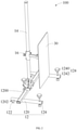
FIG. 1 shows a perspective view of a calibration device according to an embodiment of the present invention, with a laser assembly mounted on a calibration bracket of the calibration device; -
FIG. 2 shows a perspective view of the calibration device shown inFIG. 1 , with the laser assembly replaced by a calibration element; -
FIG. 3 shows a perspective view of a loading platform and the laser assembly of the calibration device shown inFIG. 1 ; -
FIG. 4 shows a perspective view of the loading platform and the laser assembly of the calibration device shown inFIG. 3 , with the laser assembly mounted in a different position; -
FIG. 5 shows a schematic view of the loading platform and the laser assembly ofFIG. 3 disassembled; -
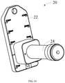
FIG. 6 shows a perspective view of the laser assembly shown inFIG. 3 ; -
FIG. 7 shows a perspective view of of the laser assembly shown inFIG. 6 from another angle; -
FIG. 8 shows a schematic view of the laser assembly shown inFIG. 6 disassembled; -
FIG. 9 shows a schematic view of the laser assembly shown inFIG. 8 disassembled from another angle; -
FIG. 10 shows a perspective view of a laser assembly of a calibration device according to another embodiment of the present invention; -
FIG. 11 shows a cross-sectional view of the laser assembly shown inFIG. 10 ; -
FIG. 12 shows a perspective view of the calibration device shown inFIG. 1 and a vehicle to be calibrated; and -
FIG. 13 shows a perspective view of the calibration device shown inFIG. 2 and a vehicle to be calibrated. - To facilitate understanding, the present invention will be described in more detail below with reference to the accompanying drawings and specific embodiments. It should be noted that that when an element is referred to as being "secured" to another element, it may be directly on the other element or intervening elements may be present. When an element is referred to as being "connected" to another element, it may be directly connected to the other element or intervening elements may be present. The terms "vertical", "horizontal", "left", "right", "inner", "outer", and the like are used herein for descriptive purposes only.
- Unless defined otherwise, all technical and scientific terms used herein have the same meaning as commonly understood by those of ordinary skill in the art to which this invention belongs. The terminology used herein is for the purpose of describing particular embodiments only and is not intended to be limiting of the invention. As used herein, the term "and/or" includes any and all combinations of one or more of the associated listed items.
- Referring to
FIGs. 1 and2 , an embodiment of the present invention provides acalibration device 100. Thecalibration device 100 includes acalibration bracket 10, alaser assembly 20 and acalibration element 30. Thelaser assembly 20 may be connected to thecalibration bracket 10 in place of thecalibration element 30. - The
calibration bracket 10 includes abase 12, apole 14, and aloading platform 16. - The
base 12 is used for supporting thepole 14, and includes abase body 120,caster wheels 122, andlevel adjusting members 124. - The
base body 120 is substantially formed by three square bars assembled by welding, and has a horizontal I-shaped structure as a whole. Thebase body 120 has anupper surface 1200 and alower surface 1202. - The
caster wheels 122 are provided on thelower surface 1202 of thebase body 120 to provide convenience for dragging thecalibration bracket 10. Twocaster wheels 122 are located at an edge of thebase body 120, and according to practical situations, the number of thecaster wheels 122 is not limited thereto, and may be 1, 3, 4, 5, etc. When the number of thecaster wheels 122 is more than 2, all thecaster wheels 122 should be in the same straight line. - The
level adjusting member 124 includes ahandle 1240 and ascrew 1242, thehandle 1240 being fixedly mounted to one end of thescrew 1242. Thescrew 1242 passes through theupper surface 1200 and thelower surface 1202, and is threadedly engaged with thebase body 120, and thescrew 1242 is vertically disposed. The handle 1244 is arranged above theupper surface 1200 for rotating thelevel adjusting member 124 such that thelevel adjusting member 124 moves in a vertical direction relative to thebase body 120 for adjusting the pitch angle of thebase body 120. Further, by moving thescrew 1242 in the vertical direction relative to thebase body 120 to an extent that thecaster wheels 122 are suspended, thebase body 120 is supported only by thelevel adjusting members 124, and thebase 12 is prevented from sliding sideways, which happens when thebase body 120 is supported by thecaster wheels 122. Threelevel adjusting members 124 are triangularly arranged, in which a connecting line of two of thelevel adjusting members 124 is substantially parallel to a connecting line of the twocaster wheels 122, and the otherlevel adjusting member 124 is located between the twocaster wheels 122. - One end of the
pole 14 is fixedly mounted to theupper surface 1200, and the length direction of thepole 14 is perpendicular to thebase body 120. Thepole 14 is used for supporting theloading platform 16. - Referring to
FIGs. 3 to 5 , theloading platform 16 is used for supporting thelaser assembly 20 and thecalibration element 30. Theloading platform 16 may support both thelaser assembly 20 and thecalibration element 30, or the loading platform may support one of thelaser assembly 20 and thecalibration element 30 separately. - The
calibration device 100 further includes amagnetic element 40 disposed on theloading platform 16 for attracting thelaser assembly 20. By means of themagnetic element 40, when thelaser assembly 20 needs to be mounted on theloading platform 16, thelaser assembly 20 only needs to approach theloading platform 16 and thelaser assembly 20 will be attracted to theloading platform 16 due to the magnetic force provided by themagnetic element 40 and, when thelaser assembly 20 needs to detach from theloading platform 16, thelaser assembly 20 only needs to be subjected to force to overcome the magnetic force provided by themagnetic element 40 in order to separate thelaser assembly 20 from theloading platform 16. It will be appreciated that, depending on the actual conditions, themagnetic element 40 may also be provided on thelaser assembly 20 for attracting theloading platform 16, that is, themagnetic element 40 is provided on one of thelaser assembly 20 and theloading platform 16 and used for attracting the other of thelaser assembly 20 and theloading platform 16. Typically, the laser assembly is attached to thecalibration device 100 to assist in positioning the calibration device relative to the vehicle, for example, the laser assembly emits a laser beam to measure the distance from the vehicle, or the laser assembly emits a laser beam to the vehicle and forms a laser line along the length of the vehicle, and thecalibration device 100 is adjusted so that the laser line is on the center plane of the vehicle, with the left and right parts of the vehicle being symmetrical relative to the center plane of the vehicle. Thus, the magnetic element is disposed on a front surface, facing the vehicle, of the loading platform, and as the front surface faces the vehicle, it is convenient to attach the laser assembly to the calibration element by means of themagnetic element 40, and the laser assembly emits a laser beam to assist in the positioning of the calibration element. - The
magnetic element 40 has a short cylindrical shape and may be made of a permanent magnetic material, such as a permanent magnetic ferrite, an Al-Ni-Co permanent magnetic alloy, or an electromagnet, such as a field coil. Themagnetic element 40 is embedded in theloading platform 16, and themagnetic element 40 is bonded to theloading platform 16 by means of back glue. After the calibration device has been positioned, i.e.. after the calibration device is in a pre-set position relative to the vehicle, generally, it needs to remove the laser and mount the calibration element on the loading platform to begin to calibrate related devices of the vehicle. According to the embodiment of the present invention, a mechanism for accommodating thelaser assembly 20 is provided in the calibration device, so that the users can conveniently store or take out thelaser assembly 20. Theloading platform 16 is provided with a mountingsurface 1600, and themagnetic element 40 is also provided on the mountingsurface 1600, by which thelaser assembly 20 is attracted to and received in the mountingsurface 1600. The mountingsurface 1600 is provided with twomagnetic elements 40, and according to actual conditions, the mountingsurface 1600 may be provided with more or lessmagnetic elements 40, for example, the number ofmagnetic elements 40 provided on the mountingsurface 1600 may also be 1, 3, 4, 5, etc. In this way, when the laser assembly is in use, thelaser assembly 20 is on the front surface of the loading platform, and thelaser assembly 20 is replaced by the calibration element and switched into a storage state on the mounting surface. Among others, the mounting surface may be provided at the front end of the loading platform facing the vehicle, i.e., parallel to and spaced from the front surface, or the mounting surface may be provided at the rear end of the loading platform facing away from the vehicle or an adjacent surface adjacent to the front surface, or the mounting surface may be provided at other parts of the calibration bracket. - In some embodiments, the mounting
surface 1600 is vertical, i.e., the mountingsurface 1600 is parallel to the length direction of thepole 14, for hanging thelaser assembly 20 on the mountingsurface 1600, and according to actual conditions, the mountingsurface 1600 may also be horizontal, i.e., the mountingsurface 1600 is perpendicular to the length direction of thepole 14, for placing thelaser assembly 20 on the mountingsurface 1600. - In some embodiments, a
positioning column 1602 is projected from the mountingsurface 1600 for positioning with thelaser assembly 20. In addition, in the case where the mountingsurface 1600 is vertically disposed, thepositioning column 1602 bears partial weight of thelaser assembly 20, thereby further improving the reliability of the connection between thelaser assembly 20 and the mountingsurface 1600. - In some embodiments, the
loading platform 16 is provided with a mountinggroove 1604 in which the mountingsurface 1600 is located, and the mountinggroove 1604 matches with thelaser assembly 20. - In some embodiments, the
loading platform 16 is provided with two mountingsurfaces 1600, and thelaser assembly 20 may be attracted to any one of the mounting surfaces 1600. By providing two mountingsurfaces 1600, after thelaser assembly 20 is used, thelaser assembly 20 may be attracted to any one of the mountingsurfaces 1600 to prevent from getting lost, which is convenient for operation. - In some embodiments, the
calibration device 100 further includes aprotection chain 50 having one end connected to theloading platform 16 and the other end connected to thelaser assembly 20. By providing theprotection chain 50, it is ensured that thelaser assembly 20 will not get lost, and at the same time, it is ensured that thelaser assembly 20 is prevented from falling down and colliding with the ground to cause damages during the process of moving thelaser assembly 20. One end of theprotection chain 50 is fixed to theloading platform 16 by a screw, the other end of theprotection chain 50 is provided with aconnection ring 51, and the other end of thelaser assembly 20 is connected to the other end of theprotection chain 50 via theconnection ring 51. - The
loading platform 16 includes a movingpart 160 and a holdingpart 162. - The
pole 14 passes through the movingpart 160, and the movingpart 160 is movable along a length direction of thepole 14 so as to adjust the height of theloading platform 16 from the ground. - Both the moving
part 160 and thepole 14 are square in cross-section so that the movingpart 160 only moves along thepole 14 and does not rotate about thepole 14. It will be appreciated that the cross-sections of the movingpart 160 and thepole 14 may also be elliptical, triangular, pentagonal, etc., as long as the cross-sections of the movingpart 160 and thepole 14 are non-circular, depending on the actual conditions. - The holding
part 162 has a horizontal bar shape, one end of which is connected to the movingpart 160, while the other end is used for supporting thelaser assembly 20 and thecalibration element 30. Onemounting surface 1600 is provided at the other end of the holdingpart 162, and the other mountingsurface 1600 is provided on the movingpart 160. - One
mounting surface 1600 is provided at a surface of the holdingpart 162 facing away from the movingpart 160. A surface of the holdingpart 162 perpendicular to the length direction of thepole 14 and adjacent to the mountingsurface 1600 serves to support thecalibration element 30. - The
calibration element 30 may be a radar calibration board, a pattern calibration board, or the like. Since the calibration element is heavier than thelaser assembly 20, the calibration element may be mounted to theloading platform 16 in other ways, such as by screws securing thecalibration element 30 to theloading platform 16. Alternatively, the calibration element may be mounted in a manner of being movable relative to theloading platform 16, as shown inFIG. 3 , the loading platform has an arcuate surface, and the calibration element is mounted on the loading platform in a manner of being movable on the arcuate surface. Furthermore, as shown inFIG. 3 , the loading platform is marked with a scale on an adjacent upper surface of the arcuate surface to identify the angle of adjustment of the calibration element, thereby improving the accuracy of adjustment. - Referring to
FIGs. 6 to 9 , thelaser assembly 20 includes a fixingseat 22 and alaser 24. - The fixing
seat 22 is used for supporting thelaser 24, and the whole fixingseat 22 is shaped like a plate and may be made of aluminum. A surface of the fixingseat 22 is provided with an attractingplate 220 to be attracted by themagnetic element 40, and the attractingplate 220 may be made of easily magnetized materials, such as iron, nickel, cobalt, etc. - It will be appreciated that, according to the actual conditions, the attracting
plate 220 may be omitted, and the fixingseat 22 may also be attracted by themagnetic element 40 by being made of a material that is attractive to themagnetic element 40. - In some embodiments, the attracting
plate 220 is embedded in the fixingseat 22 so that the attractingplate 220 does not protrude from the fixingseat 22, making the overall structure compact. - In some embodiments, the attracting
plate 220 is fixed to the fixingseat 22 by screws, and it will be appreciated that the attractingplate 220 may be fixed to the fixingseat 22 by means of gluing, welding or the like according to the actual conditions. - In some embodiments, the fixing
seat 22 is provided with achain hole 222 for theconnection ring 51 to pass through. - In some embodiments, the fixing
seat 22 is provided with apositioning hole 224. Thepositioning column 1602 is received in thepositioning hole 224 when thelaser assembly 20 is attracted and received in the mountingsurface 1600. - The other surface of the fixing
seat 22 is provided with a surface scale made by laser engraving for measuring the relative position of the calibration bracket to a vehicle to be calibrated. A mountingcylinder 226 is projected from the other surface of the fixingseat 22 for sleeving thelaser 24. - In some embodiments, The mounting
cylinder 226 is provided with afastening screw 228 penetrating therethrough in a radial direction to fix thelaser 24 to the mountingcylinder 226. - The
whole laser 24 has a long cylindrical shape, one end of thelaser 24 is used for emitting a laser light beam, and the other end of thelaser 24 is sleeved by the mountingcylinder 226. A switch of thelaser 24 is provided at the other end of thelaser 24, and the switch is apush button 240 which is exposed on a surface of the fixingseat 22 to be attracted to theloading platform 16. - Referring to
FIGs. 10 and11 together, when thelaser 24 is to be turned on or off, thelaser assembly 20 needs to be separated from theloading platform 16 to turn thelaser 24 on or off. Another embodiment of the present invention provides a calibration device in order to solve the problem of the embodiment described above that it is to cumbersome turn thelaser 24 on or off. - The calibration device is substantially the same as the
calibration device 100 of the embodiment described above, except that the fixingseat 22 is different. - The mounting
cylinder 226 is provided with a movingchannel 2260 therein, and the movingchannel 2260 has achannel bottom 2262, thelaser 24 passes through the the movingchannel 226 to be sleeved by the mountingcylinder 226, and thelaser 24 is movable along the movingchannel 226 so that thepush button 240 approaches or moves away from thechannel bottom 2262 of the movingchannel 2260. By providing the movingchannel 2260 for thelaser 24 to move, thepush button 240 may be pushed thechannel bottom 2262 by moving thelaser 24, thereby turning thelaser 24 on or off. - In some embodiments, the moving
channel 2260 is provided with anannular stop portion 2264 at an opening of the movingchannel 2260, theannular stop portion 2264 being smaller than the movingchannel 2260 in cross-sectional dimension, and the movingchannel 2260 sleeves thelaser 24 by means of theannular stop portion 2264. The other end, where thepush button 240 is arranged, of thelaser 24 is provided with anannular limit portion 242 projected in a radical direction thereof, theannular limit portion 242 being larger than thelaser 24 in cross-sectional dimension. During movement of thelaser 24, theannular limit portion 242 may abut theannular stop portion 2264 to prevent thelaser 24 from leaving the movingchannel 2260. Thechannel bottom 2262 is the attractingplate 220, and when thelaser 24 is assembled with the fixingseat 22, thelaser 24 firstly enters the movingchannel 2260 from the side of the fixedseat 22 facing away from the mountingcylinder 226, and then the attractingplate 220 is mounted to the fixedseat 24 to close the movingchannel 2260. - In some embodiments, the
laser assembly 20 further includes aresilient member 2266 for providing a resilient force to move thepush button 240 away from the thechannel bottom 2262. When thepush button 240 has been pressed by thechannel bottom 2262, the resilient force provided by theresilient member 2266 returns thelaser 24. Theresilient member 2266 is a compression spring, and according to actual conditions, theresilient member 2266 may also have a resilient structure such as a torsion spring and a spring plate. The compression spring is located in the movingchannel 2260, and both ends of the compression spring abut against thelaser 24 and thechannel bottom 2262, respectively. - In some embodiments, a
bulge 2268 is projected from thechannel bottom 2262, and is aligned with thepush button 240, thebulge 2268 being used for pressing thepush button 240. This reduces the travel of thelaser 24 within the moving channel 2600. The end of the compression spring abutting against thechannel bottom 2262 sleeves thebulge 2268, so as to position the compression spring. - Referring to
FIGs. 11 and 12 , thecalibration device 100 is specifically used as follows: - as shown in
FIGs. 1 and12 , after thecalibration bracket 100 is put in place, firstly, thelaser assembly 20 is attracted to the front surface of the holdingpart 162, and then the position of thecalibration bracket 100 and the height of theloading platform 16 from the ground are adjusted so that the laser emitted by thelaser assembly 20 is aimed at a sensor of thevehicle 200 to be calibrated or the vehicle to be calibrated, thereby completing the positioning of thecalibration bracket 100; - as shown in
FIGs. 2 and13 , thelaser assembly 20 is separated from the holdingpart 162, thelaser assembly 20 is attracted to the mountingsurface 1600 of the movingpart 160, thecalibration element 30 is mounted to the holdingpart 162, and the sensor of thevehicle 200 to be calibrated is calibrated by thecalibration element 30. - Compared with the prior art, in the
calibration device 100 provided by the embodiment of the invention, by means of themagnetic element 30, when thelaser assembly 20 needs to be mounted on theloading platform 16, thelaser assembly 20 only needs to approach theloading platform 16 and thelaser assembly 20 will be attracted to theloading platform 16 due to the magnetic force provided by themagnetic element 40 and, when thelaser assembly 20 needs to detach from theloading platform 16, thelaser assembly 20 only needs to be subjected to force to overcome the magnetic force provided by themagnetic element 40 in order to separate thelaser assembly 20 from theloading platform 16. - Additionally, by providing two mounting
surfaces 1600, thelaser assembly 20 can be put on one of the mountingsurfaces 1600 after removal from the other mountingsurface 1600, thereby preventing thelaser assembly 20 from getting lost. - Additionally, by providing the moving
channel 2260, thelaser assembly 20 need not be separated from theloading platform 16 when thelaser 24 needs to be turned on or off. - Finally, it should be noted that: the above embodiments are merely illustrative of the technical solution of the present invention, and are not limiting thereto. Combinations of features in the above embodiments or between different embodiments are also possible within the spirit of the invention, the steps may be implemented in any order, and many other variations of different aspects of the invention as described above are possible, which are not provided in detail for the sake of brevity. Although the present invention has been described in detail with reference to the foregoing embodiments, those skilled in the art will appreciate that: the technical solutions disclosed in the above-mentioned embodiments may still be modified or some of the technical features thereof may be replaced by equivalents; however, these modifications do not depart from the spirit and scope of the embodiments of the present invention.
Claims (22)
- A calibration device, comprising:a calibration bracket, comprising a pole and a loading platform, the pole being used for supporting the loading platform, and the loading platform being used for supporting a laser assembly; anda magnetic element, mounted on one of the laser assembly and the loading platform, andbeing used for attracting the other of the laser assembly and the loading platform, the magnetic element being disposed on a front surface, facing a vehicle, of the loading platform,or the magnetic element being disposed on a surface, mating with the front surface in an attractive manner, of the laser assembly.
- The calibration device according to claim 1, wherein the pole passes through the loading platform, and the loading platform is movable along a length direction of the pole.
- The calibration device according to claim 1, wherein the loading platform is provided with a mounting surface for attracting and receiving the laser assembly, the mounting surface being a surface of the loading platform other than the front surface.
- The calibration device according to claim 3, wherein the mounting surface is substantially parallel to the pole.
- The calibration device according to claim 3 or 4, wherein the loading platform is provided with a mounting groove, and the mounting surface is located in the mounting groove.
- The calibration device according to any of claims 3 to 5, wherein a positioning column is projected from the mounting surface, and the laser assembly is provided with a positioning hole; and
the positioning column is received in the positioning hole when the laser assembly is attracted to and received in the mounting surface. - The calibration device according to any of claims 3 to 6, wherein two mounting surfaces are provided, and the laser assembly is configured to be attracted to and received in one of the two mounting surfaces.
- The calibration device according to any of claims 1 to 7, wherein the calibration device further comprises a protection chain having one end connected to the loading platform and the other end connected to the laser assembly.
- The calibration device according to any of claims 1 to 8, wherein the laser assembly comprises a fixing seat and a laser;
the fixing seat being used to be attracted to the front surface of the loading platform, and the laser being mounted to the fixing seat and used for emitting laser light. - The calibration device according to claim 9, wherein the fixing seat is provided with a mounting cylinder, one end of the laser is used for emitting laser light, and the other end of the laser is sleeved by the mounting cylinder.
- The calibration device according to claim 10, wherein a switch of the laser is provided at the other end of the laser; and
the switch is exposed on a surface of the fixing seat facing away from the mounting cylinder. - The calibration device according to claim 11, wherein the mounting cylinder is provided with a fastening screw penetrating therethrough in a radial direction to fix the other end of the laser to the mounting cylinder.
- The calibration device according to any of claims 10 to 12, wherein the mounting cylinder is provided with a moving channel therein, and the moving channel has a channel bottom;the switch of the laser is provided at the other end of the laser, and the switch is a push button; andthe other end of the laser passes through the the moving channel to be sleeved by the mounting cylinder, and the laser is movable along the moving channel so that the push button approaches or moves away from the channel bottom.
- The calibration device according to claim 13, wherein the laser assembly further comprises a resilient member for providing a resilient force to move the push button away from the the channel bottom.
- The calibration device according to claim 14, wherein the resilient member is a compression spring; and
two ends of the compression spring abut against the channel bottom and the other end of the laser, respectively. - The calibration device according to claim 15, wherein a bulge is projected from the channel bottom, and is aligned with the push button.
- The calibration device according to claim 16, wherein the end of the compression spring abutting against the channel bottom sleeves the bulge.
- The calibration device according to any of claims 13 to 17, wherein the moving channel is provided with an annular stop portion at an opening of the moving channel, the annular stop portion being smaller than the moving channel in cross-sectional dimension, and the moving channel sleeves the laser by means of the annular stop portion; and
the other end of the laser is provided with an annular limit portion projected in a radical direction thereof, the annular limit portion being larger than the laser in cross-sectional dimension. - The calibration device according to any of claims 1 to 18, wherein the magnetic element is embedded in one of the laser or the loading platform.
- The calibration device according to any of claims 1 to 18, wherein the magnetic element is bonded to one of the laser or the loading platform by means of back glue.
- The calibration device according to any of claims 1 to 18, wherein one of the laser assembly and the loading platform is provided with the magnetic element, and the other of the loading platform and the laser assembly is provided with an attracting plate to be attracted by the magnetic element.
- The calibration device according to any of claims 1 to 18, wherein the calibration device further comprises a calibration element; and
the calibration element is mounted on the loading platform in place of the laser.
Applications Claiming Priority (2)
| Application Number | Priority Date | Filing Date | Title |
|---|---|---|---|
| CN201910605790.9A CN112180333A (en) | 2019-07-05 | 2019-07-05 | Calibration equipment |
| PCT/CN2020/099718 WO2021004351A1 (en) | 2019-07-05 | 2020-07-01 | Calibration device |
Publications (2)
| Publication Number | Publication Date |
|---|---|
| EP3964856A1 true EP3964856A1 (en) | 2022-03-09 |
| EP3964856A4 EP3964856A4 (en) | 2022-06-08 |
Family
ID=73914733
Family Applications (1)
| Application Number | Title | Priority Date | Filing Date |
|---|---|---|---|
| EP20837048.6A Withdrawn EP3964856A4 (en) | 2019-07-05 | 2020-07-01 | Calibration device |
Country Status (4)
| Country | Link |
|---|---|
| US (1) | US12181601B2 (en) |
| EP (1) | EP3964856A4 (en) |
| CN (1) | CN112180333A (en) |
| WO (1) | WO2021004351A1 (en) |
Families Citing this family (5)
| Publication number | Priority date | Publication date | Assignee | Title |
|---|---|---|---|---|
| USD981883S1 (en) * | 2019-08-27 | 2023-03-28 | Autel Intelligent Technology Corp., Ltd. | Calibration support |
| USD1070623S1 (en) * | 2020-07-10 | 2025-04-15 | Autel Intelligent Technology Corp., Ltd. | Calibration support device |
| CN114994660B (en) * | 2022-05-26 | 2023-07-14 | 湖南致力工程科技有限公司 | Detection device for quality of tunnel second lining |
| CN116734131B (en) * | 2023-05-31 | 2025-09-05 | 斯比夫(西安)照明技术有限公司 | Laser positioning device and method for detection equipment |
| CN119839340B (en) * | 2025-03-17 | 2025-06-20 | 上海多弗众云航空科技有限公司 | A bidirectional drilling device for connecting the aircraft fuselage frame and the wing joint |
Family Cites Families (12)
| Publication number | Priority date | Publication date | Assignee | Title |
|---|---|---|---|---|
| US6836238B1 (en) * | 2001-10-09 | 2004-12-28 | Escort Inc. | Police radar/laser detector with integral vehicle parameter display using a vehicle interface |
| DE202015106939U1 (en) * | 2015-07-29 | 2016-04-06 | Hella Gutmann Solutions GmbH | Device for calibrating at least one radar sensor |
| KR102395276B1 (en) * | 2016-09-13 | 2022-05-09 | 현대자동차주식회사 | Apparatus for inspecting driver assistance system of vehicle and method for controlling the same |
| US10323936B2 (en) * | 2016-12-30 | 2019-06-18 | Bosch Automotive Service Solutions Inc. | Calibration system for sensors and cameras on vehicles |
| CN107861110B (en) * | 2017-11-15 | 2024-07-26 | 优必选教育(深圳)有限公司 | A sensor module, a sensor system and a robot |
| CN107966690B (en) * | 2018-01-12 | 2024-05-24 | 深圳市道通科技股份有限公司 | Vehicle-mounted radar calibration equipment |
| CN207689659U (en) * | 2018-01-15 | 2018-08-03 | 杨达扬 | A kind of gun sight attachment device of the strong magnetic survey distance meter of fast disassembly type |
| CN207815081U (en) * | 2018-02-26 | 2018-09-04 | 深圳市浪尖科技有限公司 | Convenient for the night-light of pressing control |
| CN108318870B (en) * | 2018-03-07 | 2024-01-30 | 深圳市道通科技股份有限公司 | Vehicle-mounted radar calibration equipment |
| CN108454584B (en) * | 2018-04-20 | 2024-08-27 | 深圳市道通科技股份有限公司 | Automobile calibration equipment |
| CN109932693B (en) * | 2018-11-30 | 2023-09-26 | 惠州华阳通用电子有限公司 | A vehicle radar calibration device, system and method |
| CN212083654U (en) * | 2019-07-05 | 2020-12-04 | 深圳市道通科技股份有限公司 | Calibration equipment |
-
2019
- 2019-07-05 CN CN201910605790.9A patent/CN112180333A/en active Pending
-
2020
- 2020-07-01 WO PCT/CN2020/099718 patent/WO2021004351A1/en not_active Ceased
- 2020-07-01 EP EP20837048.6A patent/EP3964856A4/en not_active Withdrawn
-
2021
- 2021-11-24 US US17/535,552 patent/US12181601B2/en active Active
Also Published As
| Publication number | Publication date |
|---|---|
| CN112180333A (en) | 2021-01-05 |
| WO2021004351A1 (en) | 2021-01-14 |
| US12181601B2 (en) | 2024-12-31 |
| US20220082657A1 (en) | 2022-03-17 |
| EP3964856A4 (en) | 2022-06-08 |
Similar Documents
| Publication | Publication Date | Title |
|---|---|---|
| US12181601B2 (en) | Calibration device | |
| US11325597B2 (en) | Calibration device for lane keeping assist system | |
| EP3699050B1 (en) | Calibration device for lane keeping assist system | |
| CN108216094B (en) | Installation structure of vehicle peripheral monitoring device | |
| EP0155020A2 (en) | Sensing arrangement on a material roll | |
| DE60026175D1 (en) | DETECTOR FOR DEAD ANGLE | |
| US4827623A (en) | Apparatus for determining the alignment of vehicle wheels | |
| KR20210085734A (en) | Mounting apparatus of sensor for autonomous driving vehicle | |
| EP3366519A1 (en) | Single arm telescoping rear view assembly | |
| US10274315B2 (en) | Three-wheeled vehicle alignment rack system | |
| CN212083654U (en) | Calibration equipment | |
| US20200111360A1 (en) | Train detector for embedded rail | |
| KR20130005281U (en) | Safety tripod | |
| CN210221090U (en) | Frame floorbar detects frock | |
| JP2020112531A (en) | Adjustment tool of vehicle obstacle detection device | |
| US7148682B2 (en) | Apparatus for sensing the proximity of a vehicle to an object | |
| US10486464B2 (en) | Wheel sensor | |
| US12145495B2 (en) | Bonding equipment safety apparatus, a bonding equipment safety system and related method of use | |
| FR2700346A1 (en) | Road cone with impact triggered warning device | |
| US20230311751A1 (en) | Rear Vehicle Light Assistant Device | |
| US2791939A (en) | Mount for a rear view mirror | |
| US20070145217A1 (en) | Supporting bracket for surveying instrument | |
| US8029005B2 (en) | Immobilizer for shopping trolleys | |
| KR101972698B1 (en) | Exploration device for survey | |
| JPH0634021U (en) | Alarm type car stop |
Legal Events
| Date | Code | Title | Description |
|---|---|---|---|
| STAA | Information on the status of an ep patent application or granted ep patent |
Free format text: STATUS: THE INTERNATIONAL PUBLICATION HAS BEEN MADE |
|
| PUAI | Public reference made under article 153(3) epc to a published international application that has entered the european phase |
Free format text: ORIGINAL CODE: 0009012 |
|
| STAA | Information on the status of an ep patent application or granted ep patent |
Free format text: STATUS: REQUEST FOR EXAMINATION WAS MADE |
|
| 17P | Request for examination filed |
Effective date: 20211201 |
|
| AK | Designated contracting states |
Kind code of ref document: A1 Designated state(s): AL AT BE BG CH CY CZ DE DK EE ES FI FR GB GR HR HU IE IS IT LI LT LU LV MC MK MT NL NO PL PT RO RS SE SI SK SM TR |
|
| A4 | Supplementary search report drawn up and despatched |
Effective date: 20220510 |
|
| RIC1 | Information provided on ipc code assigned before grant |
Ipc: G01M 11/00 20060101ALI20220503BHEP Ipc: G01S 13/931 20200101ALI20220503BHEP Ipc: G01S 7/481 20060101ALI20220503BHEP Ipc: G01S 7/40 20060101ALI20220503BHEP Ipc: F16M 13/02 20060101ALI20220503BHEP Ipc: F16M 11/04 20060101AFI20220503BHEP |
|
| DAV | Request for validation of the european patent (deleted) | ||
| DAX | Request for extension of the european patent (deleted) | ||
| STAA | Information on the status of an ep patent application or granted ep patent |
Free format text: STATUS: THE APPLICATION HAS BEEN WITHDRAWN |
|
| 18W | Application withdrawn |
Effective date: 20221111 |