EP3964831A1 - Inspection device and inspection method - Google Patents
Inspection device and inspection method Download PDFInfo
- Publication number
- EP3964831A1 EP3964831A1 EP21160676.9A EP21160676A EP3964831A1 EP 3964831 A1 EP3964831 A1 EP 3964831A1 EP 21160676 A EP21160676 A EP 21160676A EP 3964831 A1 EP3964831 A1 EP 3964831A1
- Authority
- EP
- European Patent Office
- Prior art keywords
- distance
- receiver
- ultrasonic wave
- transmitter
- period
- Prior art date
- Legal status (The legal status is an assumption and is not a legal conclusion. Google has not performed a legal analysis and makes no representation as to the accuracy of the status listed.)
- Granted
Links
Images


Classifications
-
- G—PHYSICS
- G01—MEASURING; TESTING
- G01N—INVESTIGATING OR ANALYSING MATERIALS BY DETERMINING THEIR CHEMICAL OR PHYSICAL PROPERTIES
- G01N29/00—Investigating or analysing materials by the use of ultrasonic, sonic or infrasonic waves; Visualisation of the interior of objects by transmitting ultrasonic or sonic waves through the object
- G01N29/04—Analysing solids
- G01N29/043—Analysing solids in the interior, e.g. by shear waves
-
- G—PHYSICS
- G01—MEASURING; TESTING
- G01N—INVESTIGATING OR ANALYSING MATERIALS BY DETERMINING THEIR CHEMICAL OR PHYSICAL PROPERTIES
- G01N29/00—Investigating or analysing materials by the use of ultrasonic, sonic or infrasonic waves; Visualisation of the interior of objects by transmitting ultrasonic or sonic waves through the object
- G01N29/04—Analysing solids
- G01N29/11—Analysing solids by measuring attenuation of acoustic waves
-
- G—PHYSICS
- G01—MEASURING; TESTING
- G01N—INVESTIGATING OR ANALYSING MATERIALS BY DETERMINING THEIR CHEMICAL OR PHYSICAL PROPERTIES
- G01N29/00—Investigating or analysing materials by the use of ultrasonic, sonic or infrasonic waves; Visualisation of the interior of objects by transmitting ultrasonic or sonic waves through the object
- G01N29/22—Details, e.g. general constructional or apparatus details
- G01N29/223—Supports, positioning or alignment in fixed situation
-
- G—PHYSICS
- G01—MEASURING; TESTING
- G01N—INVESTIGATING OR ANALYSING MATERIALS BY DETERMINING THEIR CHEMICAL OR PHYSICAL PROPERTIES
- G01N29/00—Investigating or analysing materials by the use of ultrasonic, sonic or infrasonic waves; Visualisation of the interior of objects by transmitting ultrasonic or sonic waves through the object
- G01N29/34—Generating the ultrasonic, sonic or infrasonic waves, e.g. electronic circuits specially adapted therefor
- G01N29/341—Generating the ultrasonic, sonic or infrasonic waves, e.g. electronic circuits specially adapted therefor with time characteristics
- G01N29/343—Generating the ultrasonic, sonic or infrasonic waves, e.g. electronic circuits specially adapted therefor with time characteristics pulse waves, e.g. particular sequence of pulses, bursts
-
- G—PHYSICS
- G01—MEASURING; TESTING
- G01N—INVESTIGATING OR ANALYSING MATERIALS BY DETERMINING THEIR CHEMICAL OR PHYSICAL PROPERTIES
- G01N2291/00—Indexing codes associated with group G01N29/00
- G01N2291/04—Wave modes and trajectories
- G01N2291/048—Transmission, i.e. analysed material between transmitter and receiver
-
- G—PHYSICS
- G01—MEASURING; TESTING
- G01N—INVESTIGATING OR ANALYSING MATERIALS BY DETERMINING THEIR CHEMICAL OR PHYSICAL PROPERTIES
- G01N2291/00—Indexing codes associated with group G01N29/00
- G01N2291/10—Number of transducers
- G01N2291/102—Number of transducers one emitter, one receiver
Definitions
- Embodiments described herein generally relate to an inspection device and an inspection method.
- an inspection device that uses an ultrasonic wave or the like. It is desirable to increase the detection sensitivity.
- an inspection device includes a transmitter, a receiver, and a supporter.
- the transmitter is configured to transmit a first ultrasonic wave including a plurality of burst waves having a first period Tp.
- the receiver on which the first ultrasonic wave is incident is configured to output a signal corresponding to the incident first ultrasonic wave.
- the supporter is provided between the transmitter and the receiver.
- the supporter is configured to support an inspection object.
- the first period Tp (s), a distance Dx (m), and a velocity vx (m/s) satisfy 2 Dx /(( n + 1) ⁇ vx ) ⁇ Tp ⁇ 2 Dx /( n ⁇ vx ).
- n is 1 or 2.
- the distance Dx is a shorter distance of a first distance and a second distance.
- the first distance is a distance along a first direction between the transmitter and the supporter.
- the first direction is from the transmitter toward the receiver.
- the second distance is a distance along the first direction between the supporter and the receiver.
- the velocity vx is a propagation velocity of the first ultrasonic wave in space between the transmitter and the receiver.
- an inspection method can include transmitting, from a transmitter toward an inspection object.
- a first ultrasonic wave includes a plurality of burst waves having a first period Tp.
- the method can include inspecting the inspection object by using a receiver to receive the first ultrasonic wave after the first ultrasonic wave passes through the inspection object.
- the first period Tp (s), a distance Dx (m), and a velocity vx (m/s) satisfy 2 Dx /(( n + 1) ⁇ vx ) ⁇ Tp ⁇ 2 Dx /( n ⁇ vx ).
- n is 1 or 2.
- the distance Dx is a shorter distance of a first distance and a second distance.
- the first distance is a distance along a first direction between the inspection object and the transmitter.
- the first direction is from the transmitter toward the receiver.
- the second distance is a distance along the first direction between the inspection object and the receiver.
- the velocity vx is a propagation velocity of the first ultrasonic wave in
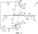
- FIG. 1 is a schematic side view illustrating an inspection device according to a first embodiment.
- the inspection device 110 includes a transmitter 10, a receiver 20, and a supporter 60.
- the transmitter 10 is configured to transmit a first ultrasonic wave 10w.
- the first ultrasonic wave 10w includes multiple burst waves having a first period Tp. Examples of the first ultrasonic wave 10w are described below.
- the first ultrasonic wave 10w is incident on the receiver 20.
- the first ultrasonic wave 10w that is incident on the receiver 20 may include reflected waves of the first ultrasonic wave 10w reflected by various members.
- the receiver 20 is configured to output a signal Sd that corresponds to the first ultrasonic wave 10w incident on the receiver 20.
- the supporter 60 is located between the transmitter 10 and the receiver 20.
- the supporter 60 is configured to support an inspection object 80.
- the supporter 60 is fed by a first feeder 61 (e.g., a roller) and a second feeder 62 (e.g., a roller).
- the inspection object 80 is placed on the supporter 60.
- the inspection object 80 is fed along a feed direction 60D as the supporter 60 is fed.
- the inspection object 80 is, for example, a banknote, etc.
- the inspection object may be a document such as a security, etc.
- the material of the inspection object 80 is arbitrary.
- the transmitter 10 includes a first membrane portion 11 that is deformable.
- the first membrane portion 11 emits the first ultrasonic wave 10w.
- a transmitting circuit 10D is connected to the transmitter 10.
- the first membrane portion 11 is deformed by a drive signal Sv from the transmitting circuit 10D and emits the first ultrasonic wave 10w.
- the deformation of the first membrane portion 11 is generated by a piezoelectric element, etc.
- the receiver 20 includes a second membrane portion 21 that is deformable.
- the second membrane portion 21 is deformed by the received first ultrasonic wave 10w.
- the signal Sd is obtained according to the deformation of the second membrane portion 21.
- the deformation of the second membrane portion 21 is converted into an electrical signal by a piezoelectric element, etc.
- a controller 70 may be provided.
- the controller 70 supplies a control signal Sc to the transmitting circuit 10D.
- the transmitting circuit 10D causes the first membrane portion 11 to deform according to the control signal Sc.
- the first ultrasonic wave 10w is emitted from the transmitter 10.
- the first ultrasonic wave 10w that is emitted from the transmitter 10 passes through the inspection object 80 and is incident on the receiver 20.
- the first ultrasonic wave 10w that is incident on the receiver 20 changes according to the state of the inspection object 80.
- the changed first ultrasonic wave 10w is received by the receiver 20.
- the signal Sd that is output from the receiver 20 reflects the state of the inspection object 80.
- the signal Sd is supplied to the controller 70.
- the controller 70 processes the signal Sd and is configured to output an inspection signal S1.
- the inspection signal S1 includes information relating to the inspection result of the inspection object 80.
- the inspection device 110 may include the transmitting circuit 10D and a receiving circuit 20D.
- the inspection device 110 may include the controller 70.
- the controller 70 may include an electrical circuit (e.g., a computer, etc.) such as a CPU (Central Processing Unit), etc.
- the first ultrasonic wave 10w that is emitted from the transmitter 10 is controlled by the drive signal Sv from the transmitting circuit 10D.
- the first period Tp of the first ultrasonic wave 10w can be controlled by the drive signal Sv.
- the duration of one of the multiple burst waves can be controlled by the drive signal Sv.
- the drive signal Sv from the transmitting circuit 10D may be controlled by the control signal Sc from the controller 70.
- the first period Tp of the first ultrasonic wave 10w may be controlled by the controller 70.
- the duration of one of the multiple burst waves may be controlled by the controller 70.
- the first ultrasonic wave 10w is appropriately controlled.
- the detection sensitivity can be increased thereby.
- the direction from the transmitter 10 toward the receiver 20 is taken as a first direction D1.
- the first direction D1 crosses the feed direction 60D.
- the first direction D1 may be oblique to the feed direction 60D.
- the distance along the first direction D1 between the transmitter 10 and the supporter 60 is taken as a first distance L1.
- the distance along the first direction D1 between the supporter 60 and the receiver 20 is taken as a second distance L2.
- the first distance L1 is the distance along the first direction D1 between the first membrane portion 11 and the supporter 60.
- the second distance L2 is the distance along the first direction D1 between the supporter 60 and the second membrane portion 21.
- the first distance L1 can be considered to be the distance between the transmitter 10 and the inspection object 80.
- the second distance L2 can be considered to be the distance between the inspection object 80 and the receiver 20.
- the second distance L2 may be equal to or different from the first distance L1.
- a distance Dx is taken to be the shorter distance of the first distance L1 and the second distance L2.
- the distance Dx corresponds to the first distance L1 (or the second distance L2).
- the distance Dx corresponds to the first distance L1.
- the distance Dx corresponds to the second distance L2.
- the first period Tp (s), the distance Dx (m), and the velocity vx (m/s) satisfy Formula (1): 2 Dx / n + 1 ⁇ vx ⁇ Tp ⁇ 2 Dx / n ⁇ vx
- n 1 or 2.
- the detection sensitivity can be increased thereby.
- the second distance L2 is taken to be greater than the first distance L1.
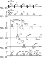
- FIGS. 2A to 2F are schematic views illustrating the inspection device according to the first embodiment.
- FIGS. 2A to 2F correspond to when the pulse width (the pulse duration) of the multiple burst waves included in the first ultrasonic wave 10w is relatively short.
- the horizontal axis is a time tm.
- FIG. 2A illustrates the first ultrasonic wave 10w emitted from the transmitter 10.
- the first ultrasonic wave 10w includes multiple burst waves 10b.
- the period of the multiple burst waves 10b is the first period Tp.
- the multiple burst waves 10b include, for example, a first pulse wave P1, a second pulse wave P2, a third pulse wave P3, etc.
- FIG. 2B schematically illustrates an intensity Int of the first ultrasonic wave 10w emitted from the transmitter 10.
- a high intensity Int that corresponds to the first pulse wave P1, the second pulse wave P2, and the third pulse wave P3 is generated.
- FIGS. 2C to 2E schematically illustrate the intensity Int of the first ultrasonic wave 10w received by the receiver 20.
- the first pulse wave P1 and pulse waves that correspond to the first pulse wave P1 are extracted in FIG. 2C .
- the second pulse wave P2 and pulse waves that correspond to the second pulse wave P2 are extracted in FIG. 2D .
- the third pulse wave P3 and pulse waves that correspond to the third pulse wave P3 are extracted in FIG. 2E .
- pulse waves Ra1, Rb1, Rc1, etc. are observed at the receiver 20.
- the intensity Int of the pulse wave Rb1 is less than the intensity Int of the pulse wave Ra1.
- the intensity Int of the pulse wave Rc1 is less than the intensity Int of the pulse wave Rb1.
- the pulse wave Ra1 corresponds to the direct wave of the first pulse wave P1.
- the pulse waves Rb1 and Rc1 correspond to reflected waves of the first pulse wave P1.
- the pulse wave Rb1 corresponds to a first reflected wave of the first pulse wave P1.
- the pulse wave Rc1 corresponds to a second reflected wave of the first pulse wave P1.
- the direct wave is the signal component from the transmitter 10 that reaches the receiver 20 via supporter 60 in the least amount of time.
- the direct wave reaches the receiver 20 without detouring due to multiple reflections, etc.
- the direct wave includes accurate information of the transmittance of the inspection object 80, etc.
- the detection sensitivity can be increased by receiving a direct wave in which the effects of noise are suppressed.
- the reflected wave reaches the receiver 20 after being reflected by the transmitter 10, the supporter 60, the receiver 20, or other members.
- the first ultrasonic wave 10w reaches the supporter 60 from the transmitter 10
- a component of a portion of the first ultrasonic wave 10w that is reflected by the supporter 60 returns to the transmitter 10.
- the first ultrasonic wave 10w that returns to the transmitter 10 is reflected by the transmitter 10, reaches the supporter 60, and subsequently reaches the receiver 20.
- Such a first ultrasonic wave 10w corresponds to a reflected wave.
- the reflected wave is temporally delayed from the direct wave when reaching the receiver 20.
- the reflected wave includes transmission and reflection information other than the inspection object 80. There are also cases where multiple reflected waves are superimposed.
- the reflected waves are noise components in the detection of the inspection object 80. Accordingly, for example, it is desirable to suppress the temporal superimposition of the direct wave and the reflected waves. For example, it is desirable for the direct wave and the reflected waves not to be excessively superimposed.
- the pulse wave Rb1 corresponds to the result of one round trip reflection of the first ultrasonic wave 10w between the transmitter 10 and the supporter 60.
- the increase amount of the propagation distance of the first ultrasonic wave 10w is 2 times the distance Dx.
- the pulse wave Rc1 corresponds to the result of two round trip reflections of the first ultrasonic wave 10w between the transmitter 10 and the supporter 60.
- the increase amount of the propagation distance of the first ultrasonic wave 10w is 4 times the distance Dx.
- a time Td between the pulse wave Ra1 and the pulse wave Rb1 corresponds to 2 Dx / vx.
- the time Td between the pulse wave Rb1 and the pulse wave Rc1 corresponds to 2 Dx / vx.
- the time tm at the start of the pulse wave Ra1 is a reference "0"
- the time tm of the start of the pulse wave Rb1 is the time Td.
- the time tm of the start of the pulse wave Rc1 is 2 times the time Td.
- pulse waves Ra2, Rb2, Rc2, etc. are observed at the receiver 20.
- the intensity Int of the pulse wave Rb2 is less than the intensity Int of the pulse wave Ra2.
- the intensity Int of the pulse wave Rc2 is less than the intensity Int of the pulse wave Rb2.
- the pulse wave Ra2 corresponds to the direct wave of the second pulse wave P2.
- the pulse waves Rb2 and Rc2 correspond to reflected waves of the second pulse wave P2.
- the pulse wave Rb2 corresponds to a first reflected wave of the second pulse wave P2.
- the pulse wave Rc2 corresponds to the second reflected wave of a second pulse wave P2.
- pulse waves Ra3, Rb3, etc. are observed at the receiver 20.
- the intensity Int of the pulse wave Rb3 is less than the intensity Int of the pulse wave Ra3.
- the pulse wave Ra3 corresponds to the direct wave of the third pulse wave P3.
- the pulse wave Rb3 corresponds to a reflected wave of the third pulse wave P3.
- the pulse wave Rb3 corresponds to a first reflected wave of the third pulse wave P3.
- the pulse waves of FIGS. 2C to 2D are overlaid in FIG. 2F .
- the direct waves of the pulse waves Ra1, Ra2, Ra3, etc. do not overlap the other pulse waves (reflected waves).
- the effects of the reflected waves on the direct waves are suppressed thereby.
- the reflected waves overlap the direct waves there are cases where the reflected waves become noise; the signal strengths of the direct waves change; and the detection sensitivity decreases.
- the effects of the reflected waves on the direct waves can be suppressed.
- an inspection device can be provided in which the detection sensitivity can be increased.
- the pulse wave Rb1 is after the pulse wave Ra2 and before the pulse wave Ra3.
- the time tm of the start of the pulse wave Rb1 is the time Td.
- the time tm of the start of the pulse wave Ra2 corresponds to the time tm of the first period Tp when referenced to "0".
- the time tm of the start of the pulse wave Ra3 corresponds to the time tm of 2 times the first period Tp when referenced to "0".
- the pulse wave Rb1 is after the pulse wave Ra2.
- Td ⁇ 2 Tp i.e., when Td /2 ⁇ Tp
- the pulse wave Rb1 is before the pulse wave Ra3.
- the time Td corresponds to 2 Dxlvx. Accordingly, when "Dx / vx ⁇ Tp", the pulse wave Rb1 is before the pulse wave Ra3.
- the pulse wave Rb1 is after the pulse wave Ra2.
- the pulse wave Rb1 may arrive after the pulse wave Ra3.
- Td ⁇ 3 Tp the pulse wave Rb1 is before the other pulse waves; and when 2 Tp ⁇ Td, the pulse wave Rb1 is after the pulse wave Ra3.
- the condition of Formula (1) is obtained: 2 Dx / n + 1 ⁇ vx ⁇ Tp ⁇ 2 Dx / n ⁇ vx
- n is an integer not less than 1.
- FIGS. 2A to 2F correspond to when n is 1.
- FIGS. 3A to 3F are schematic views illustrating the inspection device according to the first embodiment.
- FIG. 3A illustrates the first ultrasonic wave 10w emitted from the transmitter 10.
- the first ultrasonic wave 10w includes the multiple burst waves 10b.
- the period of the multiple burst waves 10b is the first period Tp.
- One (each) of the multiple burst waves 10b has a first duration Tw.
- the multiple burst waves 10b include, for example, the first pulse wave P1, the second pulse wave P2, the third pulse wave P3, etc.
- the time Td of the start of the pulse wave Rb1 illustrated in FIG. 3C is after the time of the peak ( Tp + Tw /2) of the pulse wave Ra2 illustrated in FIG. 3D .
- This condition corresponds to "Tw ⁇ ( Td - Tp ) ⁇ 2", and corresponds to "Tw ⁇ (2Dx/vx - Tp ) ⁇ 2" .
- the effects of the reflected waves on the direct waves can be further suppressed thereby.
- the effects of the reflected waves on the direct waves can be further suppressed thereby.
- the time Td of the start of the pulse wave Rb1 illustrated in FIG. 3C is after the time of the midpoint between the time of the peak ( Tp + Tw /2) and the time of the end ( Tp + Tw ) of the pulse wave Ra2 illustrated in FIG. 3D .
- the time of the midpoint corresponds to ( Tp + 3 Tw /4) .
- the effects of the reflected waves on the direct waves can be further suppressed thereby.
- the time "Td + Tw" of the end of the pulse wave Rb1 illustrated in FIG. 3C is before the time of the midpoint between the time of the start and the time of the peak (2 ⁇ Tp + Tw /2) of the pulse wave Ra3 illustrated in FIG. 3E .
- the time of the midpoint corresponds to (2 Tp + Tw /4) .
- the effects of the reflected waves on the direct waves can be further suppressed thereby.
- the time Td of the start of the pulse wave Rb1 illustrated in FIG. 3C is after the time ( Tp + Tw) of the pulse wave Ra2 illustrated in FIG. 3D .
- the effects of the reflected waves on the direct waves can be further suppressed thereby.
- the effects of the reflected waves on the direct waves can be further suppressed thereby.
- the pulse waves Rc1, Rc2, etc., that are reflected waves may overlap pulse waves Ra4 and Ra5 that are direct waves.
- the intensities Int of the pulse waves Rc1 and Rc2 are sufficiently low compared to the intensities Int of the pulse waves Ra4 and Ra5. Therefore, even when such reflected waves overlap the direct waves, the effects on the direct waves are small.
- the receiving circuit 20D, the controller 70, etc. may include a peak hold circuit.
- the signal strengths of the direct waves that have high intensities Int can be efficiently detected thereby.
- n is an integer not less than 1.
- the first period Tp (s), the distance Dx (m), the velocity vx (m/s), and the first duration Tw (s) is favorable for the first period Tp (s), the distance Dx (m), the velocity vx (m/s), and the first duration Tw (s) to satisfy Tw ⁇ 2 Dx / vx ⁇ n ⁇ Tp ⁇ 2.
- the effects of the reflected waves on the direct waves can be further suppressed thereby.
- the first period Tp (s), the distance Dx (m), the velocity vx (m/s), and the first duration Tw (s) is favorable for the first period Tp (s), the distance Dx (m), the velocity vx (m/s), and the first duration Tw (s) to satisfy Tw ⁇ n + 1 Tp ⁇ 2 Dx / vx ⁇ 2.
- the first period Tp (s), the distance Dx (m), the velocity vx (m/s), and the first duration Tw (ds) is favorable for the first period Tp (s), the distance Dx (m), the velocity vx (m/s), and the first duration Tw (ds) to satisfy Tw ⁇ 2 Dx / vx ⁇ n ⁇ Tp ⁇ 4 / 3.
- the first period Tp (s), the distance Dx (m), the velocity vx (m/s), and the first duration Tw (s) is favorable for the first period Tp (s), the distance Dx (m), the velocity vx (m/s), and the first duration Tw (s) to satisfy Tw ⁇ n + 1 Tp ⁇ 2 Dx / vx ⁇ 4 / 3.
- the first period Tp (s), the distance Dx (m), the velocity vx (m/s), and the first duration Tw (s) is favorable for the first period Tp (s), the distance Dx (m), the velocity vx (m/s), and the first duration Tw (s) to satisfy Tw ⁇ 2 Dx / vx ⁇ n ⁇ Tp .
- the first period Tp (s), the distance Dx (m), the velocity vx (m/s), and the first duration Tw (s) is desirable for the first period Tp (s), the distance Dx (m), the velocity vx (m/s), and the first duration Tw (s) to satisfy Tw ⁇ n + 1 Tp ⁇ 2 Dx / vx .
- n it is favorable for n to be 1 or 2.
- n is not less than 3, the distance L1 and the distance L2 are excessively long. Therefore, the inspection device 110 becomes large.
- the ultrasonic waves are attenuated, and it is difficult to obtain the desired sensitivity.
- n is 1 or 2
- a small and practical inspection device 110 can be provided. Because n is 1 or 2, high sensitivity can be maintained. Thereby, an inspection device can be provided in which the detection sensitivity can be increased. The distance is shorter when n is 1 than when n is 2. The attenuation can be further reduced.
- FIG. 4 is a schematic side view illustrating an inspection device according to the first embodiment.
- the inspection device 111 includes a first waveguide 15 and a second waveguide 25 in addition to the transmitter 10, the receiver 20, and the supporter 60. Otherwise, the configuration of the inspection device 111 may be similar to the configuration of the inspection device 110.
- the first waveguide 15 is located between the transmitter 10 and the supporter 60.
- the first ultrasonic wave 10w passes through the first waveguide 15.
- the first waveguide 15 guides the first ultrasonic wave 10w.
- the second waveguide 25 is located between the supporter 60 and the receiver 20.
- the first ultrasonic wave 10w passes through the second waveguide 25.
- the second waveguide 25 guides the first ultrasonic wave 10w.
- the first ultrasonic wave 10w that passes through the second waveguide 25 is incident on the receiver 20.
- the first waveguide 15 is separated from the supporter 60.
- the second waveguide 25 is separated from the supporter 60.
- the supporter 60 can move between the first waveguide 15 and the second waveguide 25.
- the spreading of the first ultrasonic wave 10w can be suppressed.
- the detection sensitivity can be further increased.
- FIG. 5 is a flowchart illustrating an inspection method according to the second embodiment.
- the inspection method includes transmitting, from the transmitter 10 (referring to FIG. 1 , etc.) toward the inspection object 80, the first ultrasonic wave 10w that includes the multiple burst waves 10b having the first period Tp (step S110).
- the inspection method includes inspecting the inspection object 80 by using the receiver 20 (referring to FIG. 1 , etc.) to receive the first ultrasonic wave 10w that passes through the inspection object 80 (step S120).
- the first period Tp (s), the distance Dx (m), and the velocity vx (m/s) satisfy Formula (1) recited above.
- the distance Dx is the shorter distance of the first distance L1 and the second distance L2.
- the first distance L1 is the distance along the first direction D1 between the inspection object 80 and the transmitter 10; and the first direction D1 is from the transmitter 10 toward the receiver 20.
- the second distance L2 is the distance along the first direction D1 between the inspection object 80 and the receiver 20.
- the velocity vx is the propagation velocity of the first ultrasonic wave 10w in space between the transmitter 10 and the receiver 20.
- an ultrasonic burst wave is transmitted at a prescribed period from an ultrasonic wave transmitter (the transmitter 10) to a receiver (the receiver 20).
- the inspection object 80 is inspected by detecting the output signal of the receiver.
- the period is less than the difference between the time of the direct wave directly reaching the receiver from the transmitter via the inspection object 80 and the time of the reflected wave initially reaching the receiver after the direct wave arrives from the transmitter.
- the period is greater than the pulse length of the burst wave.
- the reflected waves are in the temporal gaps between the multiple direct waves that directly reach the receiver.
- Embodiments may include the following configurations (technological proposals).
- an inspection device and an inspection method can be provided in which the detection sensitivity can be increased.
Landscapes
- Physics & Mathematics (AREA)
- General Health & Medical Sciences (AREA)
- Life Sciences & Earth Sciences (AREA)
- Chemical & Material Sciences (AREA)
- Analytical Chemistry (AREA)
- Biochemistry (AREA)
- Health & Medical Sciences (AREA)
- General Physics & Mathematics (AREA)
- Immunology (AREA)
- Pathology (AREA)
- Acoustics & Sound (AREA)
- Investigating Or Analyzing Materials By The Use Of Ultrasonic Waves (AREA)
- Inspection Of Paper Currency And Valuable Securities (AREA)
Abstract
Description
- Embodiments described herein generally relate to an inspection device and an inspection method.
- For example, there is an inspection device that uses an ultrasonic wave or the like. It is desirable to increase the detection sensitivity.
-
-
FIG. 1 is a schematic side view illustrating an inspection device according to a first embodiment; -
FIGS. 2A to 2F are schematic views illustrating the inspection device according to the first embodiment; -
FIGS. 3A to 3F are schematic views illustrating the inspection device according to the first embodiment; -
FIG. 4 is a schematic side view illustrating an inspection device according to the first embodiment; and -
FIG. 5 is a flowchart illustrating an inspection method according to a second embodiment. - According to one embodiment, an inspection device includes a transmitter, a receiver, and a supporter. The transmitter is configured to transmit a first ultrasonic wave including a plurality of burst waves having a first period Tp. The receiver on which the first ultrasonic wave is incident is configured to output a signal corresponding to the incident first ultrasonic wave. The supporter is provided between the transmitter and the receiver. The supporter is configured to support an inspection object. The first period Tp (s), a distance Dx (m), and a velocity vx (m/s) satisfy 2Dx/((n + 1)·vx) < Tp < 2Dx/(n·vx). n is 1 or 2. The distance Dx is a shorter distance of a first distance and a second distance. The first distance is a distance along a first direction between the transmitter and the supporter. The first direction is from the transmitter toward the receiver. The second distance is a distance along the first direction between the supporter and the receiver. The velocity vx is a propagation velocity of the first ultrasonic wave in space between the transmitter and the receiver.
- According to one embodiment, an inspection method can include transmitting, from a transmitter toward an inspection object. A first ultrasonic wave includes a plurality of burst waves having a first period Tp. The method can include inspecting the inspection object by using a receiver to receive the first ultrasonic wave after the first ultrasonic wave passes through the inspection object. The first period Tp (s), a distance Dx (m), and a velocity vx (m/s) satisfy 2Dx/((n + 1)·vx) < Tp < 2Dx/(n·vx). n is 1 or 2. The distance Dx is a shorter distance of a first distance and a second distance. The first distance is a distance along a first direction between the inspection object and the transmitter. The first direction is from the transmitter toward the receiver. The second distance is a distance along the first direction between the inspection object and the receiver. The velocity vx is a propagation velocity of the first ultrasonic wave in space between the transmitter and the receiver.
- Various embodiments are described below with reference to the accompanying drawings.
- The drawings are schematic and conceptual; and the relationships between the thickness and width of portions, the proportions of sizes among portions, etc., are not necessarily the same as the actual values. The dimensions and proportions may be illustrated differently among drawings, even for identical portions.
- In the specification and drawings, components similar to those described previously or illustrated in an antecedent drawing are marked with like reference numerals, and a detailed description is omitted as appropriate.
-
FIG. 1 is a schematic side view illustrating an inspection device according to a first embodiment. - As shown in
FIG. 1 , theinspection device 110 according to the embodiment includes atransmitter 10, areceiver 20, and asupporter 60. - The
transmitter 10 is configured to transmit a firstultrasonic wave 10w. The firstultrasonic wave 10w includes multiple burst waves having a first period Tp. Examples of the firstultrasonic wave 10w are described below. - The first
ultrasonic wave 10w is incident on thereceiver 20. In addition to a direct wave of the firstultrasonic wave 10w that is emitted from thetransmitter 10, the firstultrasonic wave 10w that is incident on thereceiver 20 may include reflected waves of the firstultrasonic wave 10w reflected by various members. Thereceiver 20 is configured to output a signal Sd that corresponds to the firstultrasonic wave 10w incident on thereceiver 20. - The
supporter 60 is located between thetransmitter 10 and thereceiver 20. Thesupporter 60 is configured to support aninspection object 80. - In the example, the
supporter 60 is fed by a first feeder 61 (e.g., a roller) and a second feeder 62 (e.g., a roller). Theinspection object 80 is placed on thesupporter 60. Theinspection object 80 is fed along afeed direction 60D as thesupporter 60 is fed. - The
inspection object 80 is, for example, a banknote, etc. The inspection object may be a document such as a security, etc. The material of theinspection object 80 is arbitrary. - For example, the
transmitter 10 includes a first membrane portion 11 that is deformable. The first membrane portion 11 emits the firstultrasonic wave 10w. A transmittingcircuit 10D is connected to thetransmitter 10. The first membrane portion 11 is deformed by a drive signal Sv from the transmittingcircuit 10D and emits the firstultrasonic wave 10w. For example, the deformation of the first membrane portion 11 is generated by a piezoelectric element, etc. - For example, the
receiver 20 includes asecond membrane portion 21 that is deformable. Thesecond membrane portion 21 is deformed by the received firstultrasonic wave 10w. The signal Sd is obtained according to the deformation of thesecond membrane portion 21. For example, the deformation of thesecond membrane portion 21 is converted into an electrical signal by a piezoelectric element, etc. - For example, a
controller 70 may be provided. For example, thecontroller 70 supplies a control signal Sc to the transmittingcircuit 10D. The transmittingcircuit 10D causes the first membrane portion 11 to deform according to the control signal Sc. Thereby, the firstultrasonic wave 10w is emitted from thetransmitter 10. For example, the firstultrasonic wave 10w that is emitted from thetransmitter 10 passes through theinspection object 80 and is incident on thereceiver 20. The firstultrasonic wave 10w that is incident on thereceiver 20 changes according to the state of theinspection object 80. The changed firstultrasonic wave 10w is received by thereceiver 20. The signal Sd that is output from thereceiver 20 reflects the state of theinspection object 80. For example, the signal Sd is supplied to thecontroller 70. Thecontroller 70 processes the signal Sd and is configured to output an inspection signal S1. The inspection signal S1 includes information relating to the inspection result of theinspection object 80. - The
inspection device 110 may include the transmittingcircuit 10D and a receivingcircuit 20D. Theinspection device 110 may include thecontroller 70. Thecontroller 70 may include an electrical circuit (e.g., a computer, etc.) such as a CPU (Central Processing Unit), etc. - The first
ultrasonic wave 10w that is emitted from thetransmitter 10 is controlled by the drive signal Sv from the transmittingcircuit 10D. For example, the first period Tp of the firstultrasonic wave 10w can be controlled by the drive signal Sv. For example, the duration of one of the multiple burst waves can be controlled by the drive signal Sv. The drive signal Sv from the transmittingcircuit 10D may be controlled by the control signal Sc from thecontroller 70. In such a case, for example, the first period Tp of the firstultrasonic wave 10w may be controlled by thecontroller 70. For example, the duration of one of the multiple burst waves may be controlled by thecontroller 70. - According to the embodiment, the first
ultrasonic wave 10w is appropriately controlled. The detection sensitivity can be increased thereby. - As shown in
FIG. 1 , the direction from thetransmitter 10 toward thereceiver 20 is taken as a first direction D1. The first direction D1 crosses thefeed direction 60D. The first direction D1 may be oblique to thefeed direction 60D. - The distance along the first direction D1 between the
transmitter 10 and thesupporter 60 is taken as a first distance L1. The distance along the first direction D1 between thesupporter 60 and thereceiver 20 is taken as a second distance L2. For example, the first distance L1 is the distance along the first direction D1 between the first membrane portion 11 and thesupporter 60. For example, the second distance L2 is the distance along the first direction D1 between thesupporter 60 and thesecond membrane portion 21. - When the thickness (the length along a direction perpendicular to the
feed direction 60D) of theinspection object 80 is sufficiently thin, the first distance L1 can be considered to be the distance between thetransmitter 10 and theinspection object 80. The second distance L2 can be considered to be the distance between theinspection object 80 and thereceiver 20. - The second distance L2 may be equal to or different from the first distance L1. A distance Dx is taken to be the shorter distance of the first distance L1 and the second distance L2. When the second distance L2 is equal to the first distance L1, the distance Dx corresponds to the first distance L1 (or the second distance L2). When the second distance L2 is greater than the first distance L1, the distance Dx corresponds to the first distance L1. When the second distance L2 is less than the first distance L1, the distance Dx corresponds to the second distance L2.
- According to the embodiment, the first period Tp (s), the distance Dx (m), and the velocity vx (m/s) satisfy Formula (1):

- In Formula (1), n is 1 or 2. As described below, the detection sensitivity can be increased thereby. To simplify the description hereinbelow, the second distance L2 is taken to be greater than the first distance L1.
-
FIGS. 2A to 2F are schematic views illustrating the inspection device according to the first embodiment. -
FIGS. 2A to 2F correspond to when the pulse width (the pulse duration) of the multiple burst waves included in the firstultrasonic wave 10w is relatively short. In these drawings, the horizontal axis is a time tm.FIG. 2A illustrates the firstultrasonic wave 10w emitted from thetransmitter 10. As shown inFIG. 2A , the firstultrasonic wave 10w includes multiple burstwaves 10b. The period of themultiple burst waves 10b is the first period Tp. The multiple burst waves 10b include, for example, a first pulse wave P1, a second pulse wave P2, a third pulse wave P3, etc. -
FIG. 2B schematically illustrates an intensity Int of the firstultrasonic wave 10w emitted from thetransmitter 10. A high intensity Int that corresponds to the first pulse wave P1, the second pulse wave P2, and the third pulse wave P3 is generated. -
FIGS. 2C to 2E schematically illustrate the intensity Int of the firstultrasonic wave 10w received by thereceiver 20. The first pulse wave P1 and pulse waves that correspond to the first pulse wave P1 are extracted inFIG. 2C . The second pulse wave P2 and pulse waves that correspond to the second pulse wave P2 are extracted inFIG. 2D . The third pulse wave P3 and pulse waves that correspond to the third pulse wave P3 are extracted inFIG. 2E . - As shown in
FIG. 2C , pulse waves Ra1, Rb1, Rc1, etc., are observed at thereceiver 20. The intensity Int of the pulse wave Rb1 is less than the intensity Int of the pulse wave Ra1. The intensity Int of the pulse wave Rc1 is less than the intensity Int of the pulse wave Rb1. For example, the pulse wave Ra1 corresponds to the direct wave of the first pulse wave P1. For example, the pulse waves Rb1 and Rc1 correspond to reflected waves of the first pulse wave P1. For example, the pulse wave Rb1 corresponds to a first reflected wave of the first pulse wave P1. For example, the pulse wave Rc1 corresponds to a second reflected wave of the first pulse wave P1. - The direct wave is the signal component from the
transmitter 10 that reaches thereceiver 20 viasupporter 60 in the least amount of time. The direct wave reaches thereceiver 20 without detouring due to multiple reflections, etc. The direct wave includes accurate information of the transmittance of theinspection object 80, etc. The detection sensitivity can be increased by receiving a direct wave in which the effects of noise are suppressed. - In the process of the reflected wave reaching the
receiver 20 from thetransmitter 10 via thesupporter 60, for example, the reflected wave reaches thereceiver 20 after being reflected by thetransmitter 10, thesupporter 60, thereceiver 20, or other members. For example, after the firstultrasonic wave 10w reaches thesupporter 60 from thetransmitter 10, a component of a portion of the firstultrasonic wave 10w that is reflected by thesupporter 60 returns to thetransmitter 10. The firstultrasonic wave 10w that returns to thetransmitter 10 is reflected by thetransmitter 10, reaches thesupporter 60, and subsequently reaches thereceiver 20. Such a firstultrasonic wave 10w corresponds to a reflected wave. The reflected wave is temporally delayed from the direct wave when reaching thereceiver 20. - The reflected wave includes transmission and reflection information other than the
inspection object 80. There are also cases where multiple reflected waves are superimposed. The reflected waves are noise components in the detection of theinspection object 80. Accordingly, for example, it is desirable to suppress the temporal superimposition of the direct wave and the reflected waves. For example, it is desirable for the direct wave and the reflected waves not to be excessively superimposed. - When the second distance L2 is greater than the first distance L1, for example, it is considered that the pulse wave Rb1 corresponds to the result of one round trip reflection of the first
ultrasonic wave 10w between thetransmitter 10 and thesupporter 60. In such a case, the increase amount of the propagation distance of the firstultrasonic wave 10w is 2 times the distance Dx. For example, it is considered that the pulse wave Rc1 corresponds to the result of two round trip reflections of the firstultrasonic wave 10w between thetransmitter 10 and thesupporter 60. In such a case, the increase amount of the propagation distance of the firstultrasonic wave 10w is 4 times the distance Dx. - As shown in
FIG. 2C , a time Td between the pulse wave Ra1 and the pulse wave Rb1 corresponds to 2Dx/vx. The time Td between the pulse wave Rb1 and the pulse wave Rc1 corresponds to 2Dx/vx. When the time tm at the start of the pulse wave Ra1 is a reference "0", the time tm of the start of the pulse wave Rb1 is the time Td. The time tm of the start of the pulse wave Rc1 is 2 times the time Td. - As shown in
FIG. 2D , pulse waves Ra2, Rb2, Rc2, etc., are observed at thereceiver 20. The intensity Int of the pulse wave Rb2 is less than the intensity Int of the pulse wave Ra2. The intensity Int of the pulse wave Rc2 is less than the intensity Int of the pulse wave Rb2. For example, the pulse wave Ra2 corresponds to the direct wave of the second pulse wave P2. For example, the pulse waves Rb2 and Rc2 correspond to reflected waves of the second pulse wave P2. For example, the pulse wave Rb2 corresponds to a first reflected wave of the second pulse wave P2. For example, the pulse wave Rc2 corresponds to the second reflected wave of a second pulse wave P2. - As shown in
FIG. 2E , pulse waves Ra3, Rb3, etc., are observed at thereceiver 20. The intensity Int of the pulse wave Rb3 is less than the intensity Int of the pulse wave Ra3. For example, the pulse wave Ra3 corresponds to the direct wave of the third pulse wave P3. For example, the pulse wave Rb3 corresponds to a reflected wave of the third pulse wave P3. For example, the pulse wave Rb3 corresponds to a first reflected wave of the third pulse wave P3. - The pulse waves of
FIGS. 2C to 2D are overlaid inFIG. 2F . In the example as shown inFIG. 2F , the direct waves of the pulse waves Ra1, Ra2, Ra3, etc., do not overlap the other pulse waves (reflected waves). The effects of the reflected waves on the direct waves are suppressed thereby. When the reflected waves overlap the direct waves, there are cases where the reflected waves become noise; the signal strengths of the direct waves change; and the detection sensitivity decreases. According to the embodiment, the effects of the reflected waves on the direct waves can be suppressed. Thereby, an inspection device can be provided in which the detection sensitivity can be increased. - In the example shown in
FIGS. 2C to 2E , the pulse wave Rb1 is after the pulse wave Ra2 and before the pulse wave Ra3. The time tm of the start of the pulse wave Rb1 is the time Td. The time tm of the start of the pulse wave Ra2 corresponds to the time tm of the first period Tp when referenced to "0". The time tm of the start of the pulse wave Ra3 corresponds to the time tm of 2 times the first period Tp when referenced to "0". - For example, when Tp < Td, the pulse wave Rb1 is after the pulse wave Ra2. For example, when Td < 2Tp, i.e., when Td/2 < Tp, the pulse wave Rb1 is before the pulse wave Ra3. As described above, the time Td corresponds to 2Dxlvx. Accordingly, when "Dx/vx < Tp", the pulse wave Rb1 is before the pulse wave Ra3. When "Tp < 2Dx/vx", the pulse wave Rb1 is after the pulse wave Ra2. By such conditions, for example, the effects of the reflected waves on the direct waves can be suppressed. Thereby, an inspection device can be provided in which the detection sensitivity can be increased.
- The pulse wave Rb1 may arrive after the pulse wave Ra3. In such a case, when Td < 3Tp, the pulse wave Rb1 is before the other pulse waves; and when 2Tp < Td, the pulse wave Rb1 is after the pulse wave Ra3. By generalizing, the condition of Formula (1) is obtained:

- n is an integer not less than 1.
FIGS. 2A to 2F correspond to when n is 1. - An example when the pulse widths (the pulse durations) of the multiple burst waves 10b are relatively long will now be described.
-
FIGS. 3A to 3F are schematic views illustrating the inspection device according to the first embodiment. - In
FIGS. 3A to 3F , the horizontal axis is the time tm.FIG. 3A illustrates the firstultrasonic wave 10w emitted from thetransmitter 10. As shown inFIG. 3A , the firstultrasonic wave 10w includes the multiple burst waves 10b. The period of themultiple burst waves 10b is the first period Tp. One (each) of themultiple burst waves 10b has a first duration Tw. In such a case as well, the multiple burst waves 10b include, for example, the first pulse wave P1, the second pulse wave P2, the third pulse wave P3, etc. - For example, it is favorable for the time Td of the start of the pulse wave Rb1 illustrated in
FIG. 3C to be after the time of the peak (Tp + Tw/2) of the pulse wave Ra2 illustrated inFIG. 3D . For example, it is favorable for "(Tp + Tw/2) < Td". This condition corresponds to "Tw < (Td - Tp)×2", and corresponds to "Tw < (2Dx/vx - Tp)×2". - In other words, according to the embodiment, it is favorable for the first period Tp (s), the distance Dx (m), the velocity vx (m/s), and the first duration Tw (s) to satisfy Formula (2):

- The effects of the reflected waves on the direct waves can be further suppressed thereby.
- For example, it is favorable for the time "Td + Tw" of the end of the pulse wave Rb1 illustrated in
FIG. 3C to be before the time of the peak (2×Tp + Tw/2) of the pulse wave Ra3 illustrated inFIG. 3E . For example, it is favorable for "(Td + Tw) < (2Tp + Tw/2)". This condition corresponds to "Tw < (2Tp - Td)×2", and corresponds to "Tw < (2Tp - 2Dx/vx)×2". - In other words, according to the embodiment, it is favorable for the first period Tp (s), the distance Dx (m), the velocity vx (m/s), and the first duration Tw (s) to satisfy Formula (3):

- The effects of the reflected waves on the direct waves can be further suppressed thereby.
- For example, it is favorable for the time Td of the start of the pulse wave Rb1 illustrated in
FIG. 3C to be after the time of the midpoint between the time of the peak (Tp + Tw/2) and the time of the end (Tp + Tw) of the pulse wave Ra2 illustrated inFIG. 3D . The time of the midpoint corresponds to (Tp + 3Tw/4). For example, it is favorable for "(Tp + 3Tw/4) < Td". This condition corresponds to "Tw < (Td - Tp)×4/3", and corresponds to "Tw < (2Dx/vx - Tp)×4/3". - In other words, according to the embodiment, it is favorable for the first period Tp (s), the distance Dx (m), the velocity vx (m/s), and the first duration Tw (s) to satisfy Formula (4):

- The effects of the reflected waves on the direct waves can be further suppressed thereby.
- For example, it is favorable for the time "Td + Tw" of the end of the pulse wave Rb1 illustrated in
FIG. 3C to be before the time of the midpoint between the time of the start and the time of the peak (2×Tp + Tw/2) of the pulse wave Ra3 illustrated inFIG. 3E . The time of the midpoint corresponds to (2Tp + Tw/4). For example, it is favorable for "(Td + Tw) < (2Tp + Tw/4)". This condition corresponds to "Tw < (2Tp - Td)×4/3", and corresponds to "Tw < (2Tp - 2Dx/vx)×4/3". - In other words, according to the embodiment, it is favorable for the first period Tp (s), the distance Dx (m), the velocity vx (m/s), and the first duration Tw (s) to satisfy Formula (5):

- The effects of the reflected waves on the direct waves can be further suppressed thereby.
- For example, it is favorable for the time Td of the start of the pulse wave Rb1 illustrated in
FIG. 3C to be after the time (Tp + Tw) of the pulse wave Ra2 illustrated inFIG. 3D . For example, it is favorable for "(Tp + Tw) < Td". This condition corresponds to "Tw < (Td - Tp)", and corresponds to "Tw < (2Dx/vx - Tp)". - In other words, according to the embodiment, it is favorable for the first period Tp (s), the distance Dx (m), the velocity vx (m/s), and the first duration Tw (s) to satisfy Formula (6):

- The effects of the reflected waves on the direct waves can be further suppressed thereby.
- For example, it is favorable for the time "Td + Tw" of the end of the pulse wave Rb1 illustrated in
FIG. 3C to be before the time of the start (2×Tp) of the pulse wave Ra3 illustrated inFIG. 3E . For example, it is favorable for "(Tp + Tw) < 2Tp". This condition corresponds to "Tw < (2Tp - Td)", and corresponds to "Tw < (2Tp - 2Dx/vx)". - In other words, according to the embodiment, it is favorable for the first period Tp (s), the distance Dx (m), the velocity vx (m/s), and the first duration Tw (s) to satisfy Formula (7):

- The effects of the reflected waves on the direct waves can be further suppressed thereby.
- As shown in
FIG. 3F , the pulse waves Rc1, Rc2, etc., that are reflected waves may overlap pulse waves Ra4 and Ra5 that are direct waves. The intensities Int of the pulse waves Rc1 and Rc2 are sufficiently low compared to the intensities Int of the pulse waves Ra4 and Ra5. Therefore, even when such reflected waves overlap the direct waves, the effects on the direct waves are small. - For example, the receiving
circuit 20D, thecontroller 70, etc., may include a peak hold circuit. The signal strengths of the direct waves that have high intensities Int can be efficiently detected thereby. - The conditions described above can be generalized similarly according to the position of the pulse wave Rb1 by using n that is an integer not less than 1.
- In other words, according to the embodiment, it is favorable for the first period Tp (s), the distance Dx (m), the velocity vx (m/s), and the first duration Tw (s) to satisfy

- The effects of the reflected waves on the direct waves can be further suppressed thereby.
- According to the embodiment, it is favorable for the first period Tp (s), the distance Dx (m), the velocity vx (m/s), and the first duration Tw (s) to satisfy

- According to the embodiment, it is favorable for the first period Tp (s), the distance Dx (m), the velocity vx (m/s), and the first duration Tw (ds) to satisfy

- According to the embodiment, it is favorable for the first period Tp (s), the distance Dx (m), the velocity vx (m/s), and the first duration Tw (s) to satisfy

- According to the embodiment, it is favorable for the first period Tp (s), the distance Dx (m), the velocity vx (m/s), and the first duration Tw (s) to satisfy

- According to the embodiment, it is desirable for the first period Tp (s), the distance Dx (m), the velocity vx (m/s), and the first duration Tw (s) to satisfy

- According to the embodiment, it is favorable for n to be 1 or 2. When n is not less than 3, the distance L1 and the distance L2 are excessively long. Therefore, the
inspection device 110 becomes large. When the distance is long, the ultrasonic waves are attenuated, and it is difficult to obtain the desired sensitivity. According to the embodiment, because n is 1 or 2, a small andpractical inspection device 110 can be provided. Because n is 1 or 2, high sensitivity can be maintained. Thereby, an inspection device can be provided in which the detection sensitivity can be increased. The distance is shorter when n is 1 than when n is 2. The attenuation can be further reduced. -
FIG. 4 is a schematic side view illustrating an inspection device according to the first embodiment. - As shown in
FIG. 4 , theinspection device 111 according to the embodiment includes afirst waveguide 15 and asecond waveguide 25 in addition to thetransmitter 10, thereceiver 20, and thesupporter 60. Otherwise, the configuration of theinspection device 111 may be similar to the configuration of theinspection device 110. - The
first waveguide 15 is located between thetransmitter 10 and thesupporter 60. The firstultrasonic wave 10w passes through thefirst waveguide 15. For example, thefirst waveguide 15 guides the firstultrasonic wave 10w. Thesecond waveguide 25 is located between thesupporter 60 and thereceiver 20. The firstultrasonic wave 10w passes through thesecond waveguide 25. For example, thesecond waveguide 25 guides the firstultrasonic wave 10w. The firstultrasonic wave 10w that passes through thesecond waveguide 25 is incident on thereceiver 20. - For example, the
first waveguide 15 is separated from thesupporter 60. Thesecond waveguide 25 is separated from thesupporter 60. Thesupporter 60 can move between thefirst waveguide 15 and thesecond waveguide 25. - By providing the waveguides, the spreading of the first
ultrasonic wave 10w can be suppressed. The detection sensitivity can be further increased. -
FIG. 5 is a flowchart illustrating an inspection method according to the second embodiment. - As shown in
FIG. 5 , the inspection method according to the embodiment includes transmitting, from the transmitter 10 (referring toFIG. 1 , etc.) toward theinspection object 80, the firstultrasonic wave 10w that includes the multiple burst waves 10b having the first period Tp (step S110). The inspection method includes inspecting theinspection object 80 by using the receiver 20 (referring toFIG. 1 , etc.) to receive the firstultrasonic wave 10w that passes through the inspection object 80 (step S120). - In the inspection method according to the embodiment, the first period Tp (s), the distance Dx (m), and the velocity vx (m/s) satisfy Formula (1) recited above. The distance Dx is the shorter distance of the first distance L1 and the second distance L2. The first distance L1 is the distance along the first direction D1 between the
inspection object 80 and thetransmitter 10; and the first direction D1 is from thetransmitter 10 toward thereceiver 20. The second distance L2 is the distance along the first direction D1 between theinspection object 80 and thereceiver 20. The velocity vx is the propagation velocity of the firstultrasonic wave 10w in space between thetransmitter 10 and thereceiver 20. By such conditions, the effects of the reflected waves on the direct waves can be further suppressed. An inspection method can be provided in which the detection sensitivity can be increased. - According to the embodiment, it is more favorable for at least one of Formula (2) to Formula (7) recited above to be satisfied. The effects of the reflected waves on the direct waves can be further suppressed. An inspection method can be provided in which the detection sensitivity can be increased.
- For example, in the inspection method according to the embodiment, an ultrasonic burst wave is transmitted at a prescribed period from an ultrasonic wave transmitter (the transmitter 10) to a receiver (the receiver 20). The
inspection object 80 is inspected by detecting the output signal of the receiver. The period is less than the difference between the time of the direct wave directly reaching the receiver from the transmitter via theinspection object 80 and the time of the reflected wave initially reaching the receiver after the direct wave arrives from the transmitter. The period is greater than the pulse length of the burst wave. The reflected waves are in the temporal gaps between the multiple direct waves that directly reach the receiver. - Embodiments may include the following configurations (technological proposals).
- Configuration 1 An inspection device, comprising:
- a transmitter configured to transmit a first ultrasonic wave, the first ultrasonic wave including a plurality of burst waves having a first period Tp;
- a receiver on which the first ultrasonic wave is incident, the receiver being configured to output a signal corresponding to the incident first ultrasonic wave; and
- a supporter provided between the transmitter and the receiver,
- the supporter being configured to support an inspection object,
- the first period Tp (s), a distance Dx (m), and a velocity vx (m/s) satisfying

- n being 1 or 2,
- the distance Dx being a shorter distance of a first distance and a second distance,
- the first distance being a distance along a first direction between the transmitter and the supporter,
- the first direction being from the transmitter toward the receiver,
- the second distance being a distance along the first direction between the supporter and the receiver,
- the velocity vx being a propagation velocity of the first ultrasonic wave in space between the transmitter and the receiver.
-
Configuration 2 The inspection device according to Configuration 1, wherein
n is 1. - Configuration 3 The inspection device according to
Configuration 1 or 2, wherein
the transmitter includes a first membrane portion emitting the first ultrasonic wave,
the first membrane portion is deformable,
the first distance is a distance along the first direction between the first membrane portion and the supporter,
the receiver includes a second membrane portion that is deformable by the received first ultrasonic wave, and
the second distance is a distance along the first direction between the supporter and the second membrane portion. -
Configuration 4 The inspection device according to any one of Configurations 1 to 3, wherein
one of the plurality of burst waves has a first duration Tw, and
the first period Tp (s), the distance Dx (m), the velocity vx (m/s), and the first duration Tw (s) satisfy
- Configuration 5 The inspection device according to
Configuration 4, wherein
the first period Tp (s), the distance Dx (m), the velocity vx (m/s), and the first duration Tw (s) satisfy
- Configuration 6 The inspection device according to
Configuration 4 or 5, wherein
the first period Tp (s), the distance Dx (m), the velocity vx (m/s), and the first duration Tw (s) satisfy
- Configuration 7 The inspection device according to any one of
Configurations 4 to 6, wherein
the first period Tp (s), the distance Dx (m), the velocity vx (m/s), and the first duration Tw (s) satisfy
- Configuration 8 The inspection device according to
Configuration 4 or 5, wherein
the first period Tp (s), the distance Dx (m), the velocity vx (m/s), and the first duration Tw (s) satisfy
- Configuration 9 The inspection device according to
Configuration 4 or 5, wherein
the first period Tp (s), the distance Dx (m), the velocity vx (m/s), and the first duration Tw (s) satisfy
-
Configuration 10 The inspection device according to any one of Configurations 1 to 9, further comprising:- a first waveguide provided between the transmitter and the supporter, the first ultrasonic wave passing through the first waveguide; and
- a second waveguide provided between the supporter and the receiver,
- the first ultrasonic wave passing through the second waveguide,
- the first ultrasonic wave being incident on the receiver after passing through the second waveguide.
- Configuration 11 The inspection device according to
Configuration 10, wherein
the first waveguide is separated from the supporter, and
the second waveguide is separated from the supporter. - Configuration 12 An inspection method, comprising:
- transmitting, from a transmitter toward an inspection object, a first ultrasonic wave including a plurality of burst waves having a first period Tp; and
- inspecting the inspection object by using a receiver to receive the first ultrasonic wave after the first ultrasonic wave passes through the inspection object,
- the first period Tp (s), a distance Dx (m), and a velocity vx (m/s) satisfying

- n being 1 or 2,
- the distance Dx being a shorter distance of a first distance and a second distance,
- the first distance being a distance along a first direction between the inspection object and the transmitter,
- the first direction being from the transmitter toward the receiver,
- the second distance being a distance along the first direction between the inspection object and the receiver,
- the velocity vx being a propagation velocity of the first ultrasonic wave in space between the transmitter and the receiver.
- Configuration 13 The inspection method according to Configuration 12, wherein
n is 1. - Configuration 14 The inspection method according to Configuration 12 or 13, wherein
one of the plurality of burst waves has a first duration Tw, and
the first period Tp (s), the distance Dx (m), the velocity vx (m/s), and the first duration Tw (s) satisfy
-
Configuration 15 The inspection method according to Configuration 14, wherein
the first period Tp (s), the distance Dx (m), the velocity vx (m/s), and the first duration Tw (s) satisfy
- Configuration 16 The inspection method according to
Configuration 14 or 15, wherein
the first period Tp (s), the distance Dx (m), the velocity vx (m/s), and the first duration Tw (s) satisfy
- Configuration 17 The inspection method according to any one of Configurations 14 to 16, wherein
the first period Tp (s), the distance Dx (m), the velocity vx (m/s), and the first duration Tw (s) satisfy
- Configuration 18 The inspection method according to
Configuration 14 or 15, wherein
the first period Tp (s), the distance Dx (m), the velocity vx (m/s), and the first duration Tw (s) satisfy
- Configuration 19 The inspection method according to
Configuration 14 or 15, wherein
the first period Tp (s), the distance Dx (m), the velocity vx (m/s), and the first duration Tw (s) satisfy
- According to embodiments, an inspection device and an inspection method can be provided in which the detection sensitivity can be increased.
- Hereinabove, exemplary embodiments of the invention are described with reference to specific examples. However, the embodiments of the invention are not limited to these specific examples. For example, one skilled in the art may similarly practice the invention by appropriately selecting specific configurations of components included in inspection devices such as transmitters, receivers, supporters, transmitting circuits, receiving circuits, controllers, etc., from known art. Such practice is included in the scope of the invention to the extent that similar effects thereto are obtained.
- Further, any two or more components of the specific examples may be combined within the extent of technical feasibility and are included in the scope of the invention to the extent that the purport of the invention is included.
- Moreover, all inspection devices, and inspection methods practicable by an appropriate design modification by one skilled in the art based on the inspection devices, and the inspection methods described above as embodiments of the invention also are within the scope of the invention to the extent that the purport of the invention is included.
- Various other variations and modifications can be conceived by those skilled in the art within the spirit of the invention, and it is understood that such variations and modifications are also encompassed within the scope of the invention.
- While certain embodiments have been described, these embodiments have been presented by way of example only, and are not intended to limit the scope of the inventions. Indeed, the novel embodiments described herein may be embodied in a variety of other forms; furthermore, various omissions, substitutions and changes in the form of the embodiments described herein may be made without departing from the spirit of the inventions. The accompanying claims and their equivalents are intended to cover such forms or modifications as would fall within the scope and spirit of the invention.
Claims (15)
- An inspection device, comprising:a transmitter configured to transmit a first ultrasonic wave, the first ultrasonic wave including a plurality of burst waves having a first period Tp;a receiver on which the first ultrasonic wave is incident, the receiver being configured to output a signal corresponding to the incident first ultrasonic wave; anda supporter provided between the transmitter and the receiver,the supporter being configured to support an inspection object,the first period Tp (s), a distance Dx (m), and a velocity vx (m/s) satisfying
 n being 1 or 2,the distance Dx being a shorter distance of a first distance and a second distance,the first distance being a distance along a first direction between the transmitter and the supporter,the first direction being from the transmitter toward the receiver,the second distance being a distance along the first direction between the supporter and the receiver,the velocity vx being a propagation velocity of the first ultrasonic wave in space between the transmitter and the receiver.
 - The device according to claim 1, wherein
n is 1. - The device according to claims 1 or 2, wherein
the transmitter includes a first membrane portion emitting the first ultrasonic wave,
the first membrane portion is deformable,
the first distance is a distance along the first direction between the first membrane portion and the supporter,
the receiver includes a second membrane portion that is deformable by the received first ultrasonic wave, and
the second distance is a distance along the first direction between the supporter and the second membrane portion. - The device according to any of claims 1-3, wherein
one of the plurality of burst waves has a first duration Tw, and
the first period Tp (s), the distance Dx (m), the velocity vx (m/s), and the first duration Tw (s) satisfy
- The device according to claim 4, wherein
the first period Tp (s), the distance Dx (m), the velocity vx (m/s), and the first duration Tw (s) satisfy
- The device according to claims 4 or 5, wherein
the first period Tp (s), the distance Dx (m), the velocity vx (m/s), and the first duration Tw (s) satisfy
- The device according to any of claims 4-6, wherein
the first period Tp (s), the distance Dx (m), the velocity vx (m/s), and the first duration Tw (s) satisfy
- The device according to claims 4 or 5, wherein
the first period Tp (s), the distance Dx (m), the velocity vx (m/s), and the first duration Tw (s) satisfy
- The device according to claims 4 or 5, wherein
the first period Tp (s), the distance Dx (m), the velocity vx (m/s), and the first duration Tw (s) satisfy
- The device according to any one of claims 1-9, further comprising:a first waveguide provided between the transmitter and the supporter, the first ultrasonic wave passing through the first waveguide; anda second waveguide provided between the supporter and the receiver,the first ultrasonic wave passing through the second waveguide,the first ultrasonic wave being incident on the receiver after passing through the second waveguide.
- The inspection device according to claim 10, wherein
the first waveguide is separated from the supporter, and
the second waveguide is separated from the supporter. - An inspection method, comprising:transmitting, from a transmitter toward an inspection object, a first ultrasonic wave including a plurality of burst waves having a first period Tp; andinspecting the inspection object by using a receiver to receive the first ultrasonic wave after the first ultrasonic wave passes through the inspection object,the first period Tp (s), a distance Dx (m), and a velocity vx (m/s) satisfying
 n being 1 or 2,the distance Dx being a shorter distance of a first distance and a second distance,the first distance being a distance along a first direction between the inspection object and the transmitter,the first direction being from the transmitter toward the receiver,the second distance being a distance along the first direction between the inspection object and the receiver,the velocity vx being a propagation velocity of the first ultrasonic wave in space between the transmitter and the receiver.
 - The method according to claim 12, wherein
n is 1. - The method according to claims 12 or 13, wherein
one of the plurality of burst waves has a first duration Tw, and
the first period Tp (s), the distance Dx (m), the velocity vx (m/s), and the first duration Tw (s) satisfy
- The method according to claim 14, wherein
the first period Tp (s), the distance Dx (m), the velocity vx (m/s), and the first duration Tw (s) satisfy
Applications Claiming Priority (1)
| Application Number | Priority Date | Filing Date | Title |
|---|---|---|---|
| JP2020148073A JP7388996B2 (en) | 2020-09-03 | 2020-09-03 | Inspection equipment and inspection method |
Publications (2)
| Publication Number | Publication Date |
|---|---|
| EP3964831A1 true EP3964831A1 (en) | 2022-03-09 |
| EP3964831B1 EP3964831B1 (en) | 2024-11-20 |
Family
ID=74858300
Family Applications (1)
| Application Number | Title | Priority Date | Filing Date |
|---|---|---|---|
| EP21160676.9A Active EP3964831B1 (en) | 2020-09-03 | 2021-03-04 | Inspection device and inspection method |
Country Status (3)
| Country | Link |
|---|---|
| US (1) | US11726066B2 (en) |
| EP (1) | EP3964831B1 (en) |
| JP (1) | JP7388996B2 (en) |
Families Citing this family (3)
| Publication number | Priority date | Publication date | Assignee | Title |
|---|---|---|---|---|
| JP7482067B2 (en) | 2021-03-10 | 2024-05-13 | 株式会社東芝 | Inspection device and inspection method |
| JP7520782B2 (en) | 2021-08-17 | 2024-07-23 | 株式会社東芝 | Inspection device, processing device, and inspection method |
| JP7805981B2 (en) | 2023-03-08 | 2026-01-26 | 株式会社東芝 | Inspection device and inspection method |
Citations (3)
| Publication number | Priority date | Publication date | Assignee | Title |
|---|---|---|---|---|
| US20130224791A1 (en) * | 2010-03-04 | 2013-08-29 | Ventana Medical Systems, Inc. | Systems and methods for monitoring tissue sample processing |
| US20140216158A1 (en) * | 2011-08-17 | 2014-08-07 | Sergio José Sanabria Martin | Air coupled ultrasonic contactless method for non-destructive determination of defects in laminated structures |
| US20170108473A1 (en) * | 2014-03-17 | 2017-04-20 | Sonimex B.V. | Mobile Ultrasonic Rail Inspection System and Method |
Family Cites Families (35)
| Publication number | Priority date | Publication date | Assignee | Title |
|---|---|---|---|---|
| JPS58198332A (en) * | 1982-05-13 | 1983-11-18 | 富士通株式会社 | Ultrasonic diagnostic apparatus |
| US4976150A (en) * | 1986-12-30 | 1990-12-11 | Bethlehem Steel Corporation | Ultrasonic transducers |
| JPH07286999A (en) * | 1994-02-28 | 1995-10-31 | Toshiba Medical Eng Co Ltd | Ultrasonic diagnostic equipment |
| JP2000025988A (en) | 1998-07-14 | 2000-01-25 | Matsushita Electric Ind Co Ltd | Method of detecting double feed of sheet material using ultrasonic waves |
| DE19844447B4 (en) * | 1998-09-28 | 2009-04-09 | Giesecke & Devrient Gmbh | Device for testing sheet material by means of sound transducers |
| JP3993366B2 (en) | 2000-06-09 | 2007-10-17 | 株式会社東芝 | Foreign matter detection device for paper sheets |
| US7130245B2 (en) | 2003-01-31 | 2006-10-31 | Canon Denshi Kabushiki Kaisha | Ultrasonic double feed detecting device |
| JP3860126B2 (en) | 2003-01-31 | 2006-12-20 | キヤノン電子株式会社 | Double feed detection device and double feed detection method |
| EP2034462A4 (en) | 2006-05-12 | 2011-05-18 | Panasonic Elec Works Co Ltd | ULTRASONIC WAVE TYPE SMOKE DETECTOR |
| US7775110B2 (en) | 2006-09-22 | 2010-08-17 | Denso Corporation | Ultrasonic sensor |
| KR20080094426A (en) | 2007-04-20 | 2008-10-23 | 기산전자 주식회사 | Tape winding detection device using ultrasonic wave and its method |
| JP5561954B2 (en) | 2008-06-13 | 2014-07-30 | キヤノン株式会社 | Basis detection sensor for recording medium and image forming apparatus |
| JP5274370B2 (en) | 2008-06-13 | 2013-08-28 | キヤノン株式会社 | Recording medium discriminating apparatus and image forming apparatus |
| JP2013217926A (en) | 2008-06-13 | 2013-10-24 | Canon Inc | Recording medium discriminating apparatus and image forming apparatus |
| JP5855168B2 (en) | 2008-06-13 | 2016-02-09 | キヤノン株式会社 | Basis detection sensor for recording medium and image forming apparatus |
| KR100984767B1 (en) | 2008-12-22 | 2010-10-01 | 주식회사 카스모아이티 | Tape winding detection device with temperature control applied to banknote counter and bill dispenser |
| JP2011145280A (en) | 2009-12-16 | 2011-07-28 | Canon Inc | Device for determination of recording medium, and image forming apparatus |
| US20120061901A1 (en) | 2010-09-10 | 2012-03-15 | Kabushiki Kaisha Toshiba | Ultrasonic detecting device and sheet handling apparatus comprising ultrasonic detecting device |
| JP2012063276A (en) | 2010-09-16 | 2012-03-29 | Toshiba Corp | Ultrasonic inspection device, and paper sheet processor including the ultrasonic inspection device |
| JP5505251B2 (en) | 2010-10-19 | 2014-05-28 | セイコーエプソン株式会社 | Blood vessel diameter measuring device |
| US9561522B2 (en) * | 2011-03-28 | 2017-02-07 | Helmut Knorr | Ultrasonic transmitting and receiving device for thickness and/or grammage measurement |
| JP5831080B2 (en) | 2011-09-16 | 2015-12-09 | 株式会社リコー | Double feed detection device and image forming apparatus |
| US9542787B2 (en) | 2013-03-15 | 2017-01-10 | De La Rue North America Inc. | Systems and methods for detecting a document attribute using acoustics |
| JP6463920B2 (en) | 2013-08-05 | 2019-02-06 | キヤノン株式会社 | Ultrasonic transmission device, ultrasonic reception device, sheet discrimination device and image forming device |
| JP6581712B2 (en) | 2013-08-05 | 2019-09-25 | キヤノン株式会社 | Ultrasonic transmission device, ultrasonic reception device, sheet discrimination device and image forming device |
| JP2015097733A (en) | 2013-11-20 | 2015-05-28 | セイコーエプソン株式会社 | Ultrasonic device, manufacturing method thereof, electronic apparatus, and ultrasonic imaging apparatus |
| JP2017021255A (en) | 2015-07-13 | 2017-01-26 | キヤノン株式会社 | Image forming apparatus |
| JP2018132481A (en) | 2017-02-17 | 2018-08-23 | 学校法人桐蔭学園 | Analyzer and analysis system |
| JP6685982B2 (en) | 2017-09-20 | 2020-04-22 | 株式会社東芝 | Transducers and test equipment |
| JP6757350B2 (en) | 2018-03-15 | 2020-09-16 | 株式会社東芝 | Inspection equipment and inspection method |
| JP7110719B2 (en) | 2018-05-17 | 2022-08-02 | セイコーエプソン株式会社 | Ultrasonic sensors and electronics |
| JP7176286B2 (en) | 2018-08-09 | 2022-11-22 | セイコーエプソン株式会社 | Ultrasonic device and ultrasonic sensor |
| JP6862398B2 (en) | 2018-09-11 | 2021-04-21 | 株式会社東芝 | Ultrasonic equipment and inspection equipment |
| JP7216324B2 (en) | 2019-01-29 | 2023-02-01 | セイコーエプソン株式会社 | Type determination device, electronic device, and type determination method |
| JP7249924B2 (en) | 2019-10-23 | 2023-03-31 | 株式会社東芝 | Sensors and inspection equipment |
-
2020
- 2020-09-03 JP JP2020148073A patent/JP7388996B2/en active Active
-
2021
- 2021-03-04 US US17/192,024 patent/US11726066B2/en active Active
- 2021-03-04 EP EP21160676.9A patent/EP3964831B1/en active Active
Patent Citations (3)
| Publication number | Priority date | Publication date | Assignee | Title |
|---|---|---|---|---|
| US20130224791A1 (en) * | 2010-03-04 | 2013-08-29 | Ventana Medical Systems, Inc. | Systems and methods for monitoring tissue sample processing |
| US20140216158A1 (en) * | 2011-08-17 | 2014-08-07 | Sergio José Sanabria Martin | Air coupled ultrasonic contactless method for non-destructive determination of defects in laminated structures |
| US20170108473A1 (en) * | 2014-03-17 | 2017-04-20 | Sonimex B.V. | Mobile Ultrasonic Rail Inspection System and Method |
Also Published As
| Publication number | Publication date |
|---|---|
| JP7388996B2 (en) | 2023-11-29 |
| US11726066B2 (en) | 2023-08-15 |
| EP3964831B1 (en) | 2024-11-20 |
| US20220065820A1 (en) | 2022-03-03 |
| JP2022042612A (en) | 2022-03-15 |
Similar Documents
| Publication | Publication Date | Title |
|---|---|---|
| EP3964831B1 (en) | Inspection device and inspection method | |
| KR20200111768A (en) | Method and apparatus for operating a plurality of sensors in a vehicle | |
| CN110007308B (en) | Ultrasonic sensor and vehicle control system | |
| US20170057768A1 (en) | Sheet conveyance apparatus that detects overlapping of plurality of sheets, and image reading apparatus | |
| EP0098160A1 (en) | Method and apparatus for measuring distance | |
| US11307174B2 (en) | Ultrasonic flaw detection device | |
| US11287461B2 (en) | Testing an energy transmission network and localizing a fault location in an energy transmission cable | |
| KR102679276B1 (en) | Lidar sensor apparatus and control method thereof | |
| RU2375723C2 (en) | Interrogating radar of active request-response system | |
| US7663536B2 (en) | Apparatus and method for estimating distance using time of arrival | |
| CN116400339A (en) | Distance measuring device and method for functional checking of a distance measuring device | |
| US10761185B2 (en) | Signal processing device, signal processing method, recording medium, target detection device, and target detection method | |
| US7518546B2 (en) | Method and apparatus for measuring distance using low clock rate signal | |
| WO2013014931A1 (en) | Radar receiver | |
| CN106199738A (en) | There is detection device and method in object | |
| US11703479B2 (en) | Inspection device, processing device and inspection method | |
| JP4794876B2 (en) | Laser radar equipment | |
| JP2009099020A (en) | Microwave sensor | |
| JP7342646B2 (en) | Inspection method and inspection device | |
| US11898991B2 (en) | Inspection device and inspection method | |
| US20010049962A1 (en) | Electronic scanning ultrasonic object-detection apparatus and method thereof | |
| US10281572B1 (en) | Phase correction for object detection including TDMA | |
| US20200150257A1 (en) | Generation of a family of orthogonal signals for a cdma radar system | |
| EP2322947A3 (en) | Radar apparatus | |
| JP5457693B2 (en) | Object detection device |
Legal Events
| Date | Code | Title | Description |
|---|---|---|---|
| PUAI | Public reference made under article 153(3) epc to a published international application that has entered the european phase |
Free format text: ORIGINAL CODE: 0009012 |
|
| STAA | Information on the status of an ep patent application or granted ep patent |
Free format text: STATUS: REQUEST FOR EXAMINATION WAS MADE |
|
| 17P | Request for examination filed |
Effective date: 20210304 |
|
| AK | Designated contracting states |
Kind code of ref document: A1 Designated state(s): AL AT BE BG CH CY CZ DE DK EE ES FI FR GB GR HR HU IE IS IT LI LT LU LV MC MK MT NL NO PL PT RO RS SE SI SK SM TR |
|
| GRAP | Despatch of communication of intention to grant a patent |
Free format text: ORIGINAL CODE: EPIDOSNIGR1 |
|
| STAA | Information on the status of an ep patent application or granted ep patent |
Free format text: STATUS: GRANT OF PATENT IS INTENDED |
|
| INTG | Intention to grant announced |
Effective date: 20240404 |
|
| GRAJ | Information related to disapproval of communication of intention to grant by the applicant or resumption of examination proceedings by the epo deleted |
Free format text: ORIGINAL CODE: EPIDOSDIGR1 |
|
| STAA | Information on the status of an ep patent application or granted ep patent |
Free format text: STATUS: REQUEST FOR EXAMINATION WAS MADE |
|
| GRAP | Despatch of communication of intention to grant a patent |
Free format text: ORIGINAL CODE: EPIDOSNIGR1 |
|
| STAA | Information on the status of an ep patent application or granted ep patent |
Free format text: STATUS: GRANT OF PATENT IS INTENDED |
|
| INTC | Intention to grant announced (deleted) | ||
| INTG | Intention to grant announced |
Effective date: 20240812 |
|
| GRAS | Grant fee paid |
Free format text: ORIGINAL CODE: EPIDOSNIGR3 |
|
| GRAA | (expected) grant |
Free format text: ORIGINAL CODE: 0009210 |
|
| STAA | Information on the status of an ep patent application or granted ep patent |
Free format text: STATUS: THE PATENT HAS BEEN GRANTED |
|
| AK | Designated contracting states |
Kind code of ref document: B1 Designated state(s): AL AT BE BG CH CY CZ DE DK EE ES FI FR GB GR HR HU IE IS IT LI LT LU LV MC MK MT NL NO PL PT RO RS SE SI SK SM TR |
|
| REG | Reference to a national code |
Ref country code: GB Ref legal event code: FG4D |
|
| REG | Reference to a national code |
Ref country code: CH Ref legal event code: EP |
|
| REG | Reference to a national code |
Ref country code: DE Ref legal event code: R096 Ref document number: 602021021959 Country of ref document: DE |
|
| REG | Reference to a national code |
Ref country code: IE Ref legal event code: FG4D |
|
| REG | Reference to a national code |
Ref country code: LT Ref legal event code: MG9D |
|
| REG | Reference to a national code |
Ref country code: NL Ref legal event code: MP Effective date: 20241120 |
|
| PG25 | Lapsed in a contracting state [announced via postgrant information from national office to epo] |
Ref country code: PT Free format text: LAPSE BECAUSE OF FAILURE TO SUBMIT A TRANSLATION OF THE DESCRIPTION OR TO PAY THE FEE WITHIN THE PRESCRIBED TIME-LIMIT Effective date: 20250320 Ref country code: HR Free format text: LAPSE BECAUSE OF FAILURE TO SUBMIT A TRANSLATION OF THE DESCRIPTION OR TO PAY THE FEE WITHIN THE PRESCRIBED TIME-LIMIT Effective date: 20241120 Ref country code: IS Free format text: LAPSE BECAUSE OF FAILURE TO SUBMIT A TRANSLATION OF THE DESCRIPTION OR TO PAY THE FEE WITHIN THE PRESCRIBED TIME-LIMIT Effective date: 20250320 |
|
| PG25 | Lapsed in a contracting state [announced via postgrant information from national office to epo] |
Ref country code: NL Free format text: LAPSE BECAUSE OF FAILURE TO SUBMIT A TRANSLATION OF THE DESCRIPTION OR TO PAY THE FEE WITHIN THE PRESCRIBED TIME-LIMIT Effective date: 20241120 Ref country code: FI Free format text: LAPSE BECAUSE OF FAILURE TO SUBMIT A TRANSLATION OF THE DESCRIPTION OR TO PAY THE FEE WITHIN THE PRESCRIBED TIME-LIMIT Effective date: 20241120 |
|
| REG | Reference to a national code |
Ref country code: AT Ref legal event code: MK05 Ref document number: 1743996 Country of ref document: AT Kind code of ref document: T Effective date: 20241120 |
|
| PG25 | Lapsed in a contracting state [announced via postgrant information from national office to epo] |
Ref country code: BG Free format text: LAPSE BECAUSE OF FAILURE TO SUBMIT A TRANSLATION OF THE DESCRIPTION OR TO PAY THE FEE WITHIN THE PRESCRIBED TIME-LIMIT Effective date: 20241120 |
|
| PG25 | Lapsed in a contracting state [announced via postgrant information from national office to epo] |
Ref country code: ES Free format text: LAPSE BECAUSE OF FAILURE TO SUBMIT A TRANSLATION OF THE DESCRIPTION OR TO PAY THE FEE WITHIN THE PRESCRIBED TIME-LIMIT Effective date: 20241120 |
|
| PG25 | Lapsed in a contracting state [announced via postgrant information from national office to epo] |
Ref country code: NO Free format text: LAPSE BECAUSE OF FAILURE TO SUBMIT A TRANSLATION OF THE DESCRIPTION OR TO PAY THE FEE WITHIN THE PRESCRIBED TIME-LIMIT Effective date: 20250220 |
|
| PG25 | Lapsed in a contracting state [announced via postgrant information from national office to epo] |
Ref country code: LV Free format text: LAPSE BECAUSE OF FAILURE TO SUBMIT A TRANSLATION OF THE DESCRIPTION OR TO PAY THE FEE WITHIN THE PRESCRIBED TIME-LIMIT Effective date: 20241120 Ref country code: AT Free format text: LAPSE BECAUSE OF FAILURE TO SUBMIT A TRANSLATION OF THE DESCRIPTION OR TO PAY THE FEE WITHIN THE PRESCRIBED TIME-LIMIT Effective date: 20241120 Ref country code: GR Free format text: LAPSE BECAUSE OF FAILURE TO SUBMIT A TRANSLATION OF THE DESCRIPTION OR TO PAY THE FEE WITHIN THE PRESCRIBED TIME-LIMIT Effective date: 20250221 |
|
| PG25 | Lapsed in a contracting state [announced via postgrant information from national office to epo] |
Ref country code: PL Free format text: LAPSE BECAUSE OF FAILURE TO SUBMIT A TRANSLATION OF THE DESCRIPTION OR TO PAY THE FEE WITHIN THE PRESCRIBED TIME-LIMIT Effective date: 20241120 |
|
| PG25 | Lapsed in a contracting state [announced via postgrant information from national office to epo] |
Ref country code: RS Free format text: LAPSE BECAUSE OF FAILURE TO SUBMIT A TRANSLATION OF THE DESCRIPTION OR TO PAY THE FEE WITHIN THE PRESCRIBED TIME-LIMIT Effective date: 20250220 |
|
| PG25 | Lapsed in a contracting state [announced via postgrant information from national office to epo] |
Ref country code: SM Free format text: LAPSE BECAUSE OF FAILURE TO SUBMIT A TRANSLATION OF THE DESCRIPTION OR TO PAY THE FEE WITHIN THE PRESCRIBED TIME-LIMIT Effective date: 20241120 |
|
| PG25 | Lapsed in a contracting state [announced via postgrant information from national office to epo] |
Ref country code: DK Free format text: LAPSE BECAUSE OF FAILURE TO SUBMIT A TRANSLATION OF THE DESCRIPTION OR TO PAY THE FEE WITHIN THE PRESCRIBED TIME-LIMIT Effective date: 20241120 |
|
| PG25 | Lapsed in a contracting state [announced via postgrant information from national office to epo] |
Ref country code: EE Free format text: LAPSE BECAUSE OF FAILURE TO SUBMIT A TRANSLATION OF THE DESCRIPTION OR TO PAY THE FEE WITHIN THE PRESCRIBED TIME-LIMIT Effective date: 20241120 |
|
| PG25 | Lapsed in a contracting state [announced via postgrant information from national office to epo] |
Ref country code: RO Free format text: LAPSE BECAUSE OF FAILURE TO SUBMIT A TRANSLATION OF THE DESCRIPTION OR TO PAY THE FEE WITHIN THE PRESCRIBED TIME-LIMIT Effective date: 20241120 |
|
| PG25 | Lapsed in a contracting state [announced via postgrant information from national office to epo] |
Ref country code: SK Free format text: LAPSE BECAUSE OF FAILURE TO SUBMIT A TRANSLATION OF THE DESCRIPTION OR TO PAY THE FEE WITHIN THE PRESCRIBED TIME-LIMIT Effective date: 20241120 |
|
| PG25 | Lapsed in a contracting state [announced via postgrant information from national office to epo] |
Ref country code: CZ Free format text: LAPSE BECAUSE OF FAILURE TO SUBMIT A TRANSLATION OF THE DESCRIPTION OR TO PAY THE FEE WITHIN THE PRESCRIBED TIME-LIMIT Effective date: 20241120 |
|
| REG | Reference to a national code |
Ref country code: DE Ref legal event code: R097 Ref document number: 602021021959 Country of ref document: DE |
|
| RAP2 | Party data changed (patent owner data changed or rights of a patent transferred) |
Owner name: KABUSHIKI KAISHA TOSHIBA |
|
| PG25 | Lapsed in a contracting state [announced via postgrant information from national office to epo] |
Ref country code: SE Free format text: LAPSE BECAUSE OF FAILURE TO SUBMIT A TRANSLATION OF THE DESCRIPTION OR TO PAY THE FEE WITHIN THE PRESCRIBED TIME-LIMIT Effective date: 20241120 |
|
| PLBE | No opposition filed within time limit |
Free format text: ORIGINAL CODE: 0009261 |
|
| STAA | Information on the status of an ep patent application or granted ep patent |
Free format text: STATUS: NO OPPOSITION FILED WITHIN TIME LIMIT |
|
| REG | Reference to a national code |
Ref country code: DE Ref legal event code: R119 Ref document number: 602021021959 Country of ref document: DE |
|
| PG25 | Lapsed in a contracting state [announced via postgrant information from national office to epo] |
Ref country code: MC Free format text: LAPSE BECAUSE OF FAILURE TO SUBMIT A TRANSLATION OF THE DESCRIPTION OR TO PAY THE FEE WITHIN THE PRESCRIBED TIME-LIMIT Effective date: 20241120 |
|
| 26N | No opposition filed |
Effective date: 20250821 |
|
| REG | Reference to a national code |
Ref country code: CH Ref legal event code: H13 Free format text: ST27 STATUS EVENT CODE: U-0-0-H10-H13 (AS PROVIDED BY THE NATIONAL OFFICE) Effective date: 20251023 |
|
| PG25 | Lapsed in a contracting state [announced via postgrant information from national office to epo] |
Ref country code: LU Free format text: LAPSE BECAUSE OF NON-PAYMENT OF DUE FEES Effective date: 20250304 |
|
| GBPC | Gb: european patent ceased through non-payment of renewal fee |
Effective date: 20250304 |
|
| REG | Reference to a national code |
Ref country code: BE Ref legal event code: MM Effective date: 20250331 |
|
| PG25 | Lapsed in a contracting state [announced via postgrant information from national office to epo] |
Ref country code: DE Free format text: LAPSE BECAUSE OF NON-PAYMENT OF DUE FEES Effective date: 20251001 |
|
| PG25 | Lapsed in a contracting state [announced via postgrant information from national office to epo] |
Ref country code: GB Free format text: LAPSE BECAUSE OF NON-PAYMENT OF DUE FEES Effective date: 20250304 |
|
| PGFP | Annual fee paid to national office [announced via postgrant information from national office to epo] |
Ref country code: FR Payment date: 20251231 Year of fee payment: 6 |
|
| PG25 | Lapsed in a contracting state [announced via postgrant information from national office to epo] |
Ref country code: BE Free format text: LAPSE BECAUSE OF NON-PAYMENT OF DUE FEES Effective date: 20250331 |
|
| PG25 | Lapsed in a contracting state [announced via postgrant information from national office to epo] |
Ref country code: CH Free format text: LAPSE BECAUSE OF NON-PAYMENT OF DUE FEES Effective date: 20250331 |
|
| PG25 | Lapsed in a contracting state [announced via postgrant information from national office to epo] |
Ref country code: IE Free format text: LAPSE BECAUSE OF NON-PAYMENT OF DUE FEES Effective date: 20250304 |
|
| PGFP | Annual fee paid to national office [announced via postgrant information from national office to epo] |
Ref country code: IT Payment date: 20260220 Year of fee payment: 6 |