EP3964746B1 - Composite storage tank for gaseous hydrogen - Google Patents
Composite storage tank for gaseous hydrogen Download PDFInfo
- Publication number
- EP3964746B1 EP3964746B1 EP21189254.2A EP21189254A EP3964746B1 EP 3964746 B1 EP3964746 B1 EP 3964746B1 EP 21189254 A EP21189254 A EP 21189254A EP 3964746 B1 EP3964746 B1 EP 3964746B1
- Authority
- EP
- European Patent Office
- Prior art keywords
- tank
- composite
- storage tank
- metallic
- hydrogen
- Prior art date
- Legal status (The legal status is an assumption and is not a legal conclusion. Google has not performed a legal analysis and makes no representation as to the accuracy of the status listed.)
- Active
Links
Images


Classifications
-
- F—MECHANICAL ENGINEERING; LIGHTING; HEATING; WEAPONS; BLASTING
- F17—STORING OR DISTRIBUTING GASES OR LIQUIDS
- F17C—VESSELS FOR CONTAINING OR STORING COMPRESSED, LIQUEFIED OR SOLIDIFIED GASES; FIXED-CAPACITY GAS-HOLDERS; FILLING VESSELS WITH, OR DISCHARGING FROM VESSELS, COMPRESSED, LIQUEFIED, OR SOLIDIFIED GASES
- F17C13/00—Details of vessels or of the filling or discharging of vessels
- F17C13/12—Arrangements or mounting of devices for preventing or minimising the effect of explosion ; Other safety measures
-
- B—PERFORMING OPERATIONS; TRANSPORTING
- B60—VEHICLES IN GENERAL
- B60L—PROPULSION OF ELECTRICALLY-PROPELLED VEHICLES; SUPPLYING ELECTRIC POWER FOR AUXILIARY EQUIPMENT OF ELECTRICALLY-PROPELLED VEHICLES; ELECTRODYNAMIC BRAKE SYSTEMS FOR VEHICLES IN GENERAL; MAGNETIC SUSPENSION OR LEVITATION FOR VEHICLES; MONITORING OPERATING VARIABLES OF ELECTRICALLY-PROPELLED VEHICLES; ELECTRIC SAFETY DEVICES FOR ELECTRICALLY-PROPELLED VEHICLES
- B60L50/00—Electric propulsion with power supplied within the vehicle
- B60L50/50—Electric propulsion with power supplied within the vehicle using propulsion power supplied by batteries or fuel cells
- B60L50/70—Electric propulsion with power supplied within the vehicle using propulsion power supplied by batteries or fuel cells using power supplied by fuel cells
-
- B—PERFORMING OPERATIONS; TRANSPORTING
- B64—AIRCRAFT; AVIATION; COSMONAUTICS
- B64D—EQUIPMENT FOR FITTING IN OR TO AIRCRAFT; FLIGHT SUITS; PARACHUTES; ARRANGEMENT OR MOUNTING OF POWER PLANTS OR PROPULSION TRANSMISSIONS IN AIRCRAFT
- B64D27/00—Arrangement or mounting of power plants in aircraft; Aircraft characterised by the type or position of power plants
- B64D27/02—Aircraft characterised by the type or position of power plants
- B64D27/10—Aircraft characterised by the type or position of power plants of gas-turbine type
-
- B—PERFORMING OPERATIONS; TRANSPORTING
- B64—AIRCRAFT; AVIATION; COSMONAUTICS
- B64D—EQUIPMENT FOR FITTING IN OR TO AIRCRAFT; FLIGHT SUITS; PARACHUTES; ARRANGEMENT OR MOUNTING OF POWER PLANTS OR PROPULSION TRANSMISSIONS IN AIRCRAFT
- B64D37/00—Arrangements in connection with fuel supply for power plant
- B64D37/02—Tanks
- B64D37/06—Constructional adaptations thereof
-
- F—MECHANICAL ENGINEERING; LIGHTING; HEATING; WEAPONS; BLASTING
- F17—STORING OR DISTRIBUTING GASES OR LIQUIDS
- F17C—VESSELS FOR CONTAINING OR STORING COMPRESSED, LIQUEFIED OR SOLIDIFIED GASES; FIXED-CAPACITY GAS-HOLDERS; FILLING VESSELS WITH, OR DISCHARGING FROM VESSELS, COMPRESSED, LIQUEFIED, OR SOLIDIFIED GASES
- F17C1/00—Pressure vessels, e.g. gas cylinder, gas tank, replaceable cartridge
- F17C1/005—Storage of gas or gaseous mixture at high pressure and at high density condition, e.g. in the single state phase
-
- F—MECHANICAL ENGINEERING; LIGHTING; HEATING; WEAPONS; BLASTING
- F17—STORING OR DISTRIBUTING GASES OR LIQUIDS
- F17C—VESSELS FOR CONTAINING OR STORING COMPRESSED, LIQUEFIED OR SOLIDIFIED GASES; FIXED-CAPACITY GAS-HOLDERS; FILLING VESSELS WITH, OR DISCHARGING FROM VESSELS, COMPRESSED, LIQUEFIED, OR SOLIDIFIED GASES
- F17C13/00—Details of vessels or of the filling or discharging of vessels
- F17C13/02—Special adaptations of indicating, measuring, or monitoring equipment
-
- H—ELECTRICITY
- H01—ELECTRIC ELEMENTS
- H01M—PROCESSES OR MEANS, e.g. BATTERIES, FOR THE DIRECT CONVERSION OF CHEMICAL ENERGY INTO ELECTRICAL ENERGY
- H01M8/00—Fuel cells; Manufacture thereof
- H01M8/04—Auxiliary arrangements, e.g. for control of pressure or for circulation of fluids
- H01M8/04082—Arrangements for control of reactant parameters, e.g. pressure or concentration
- H01M8/04201—Reactant storage and supply, e.g. means for feeding, pipes
-
- B—PERFORMING OPERATIONS; TRANSPORTING
- B60—VEHICLES IN GENERAL
- B60L—PROPULSION OF ELECTRICALLY-PROPELLED VEHICLES; SUPPLYING ELECTRIC POWER FOR AUXILIARY EQUIPMENT OF ELECTRICALLY-PROPELLED VEHICLES; ELECTRODYNAMIC BRAKE SYSTEMS FOR VEHICLES IN GENERAL; MAGNETIC SUSPENSION OR LEVITATION FOR VEHICLES; MONITORING OPERATING VARIABLES OF ELECTRICALLY-PROPELLED VEHICLES; ELECTRIC SAFETY DEVICES FOR ELECTRICALLY-PROPELLED VEHICLES
- B60L2200/00—Type of vehicles
- B60L2200/10—Air crafts
-
- B—PERFORMING OPERATIONS; TRANSPORTING
- B64—AIRCRAFT; AVIATION; COSMONAUTICS
- B64D—EQUIPMENT FOR FITTING IN OR TO AIRCRAFT; FLIGHT SUITS; PARACHUTES; ARRANGEMENT OR MOUNTING OF POWER PLANTS OR PROPULSION TRANSMISSIONS IN AIRCRAFT
- B64D27/00—Arrangement or mounting of power plants in aircraft; Aircraft characterised by the type or position of power plants
- B64D27/02—Aircraft characterised by the type or position of power plants
- B64D27/026—Aircraft characterised by the type or position of power plants comprising different types of power plants, e.g. combination of a piston engine and a gas-turbine
-
- B—PERFORMING OPERATIONS; TRANSPORTING
- B64—AIRCRAFT; AVIATION; COSMONAUTICS
- B64D—EQUIPMENT FOR FITTING IN OR TO AIRCRAFT; FLIGHT SUITS; PARACHUTES; ARRANGEMENT OR MOUNTING OF POWER PLANTS OR PROPULSION TRANSMISSIONS IN AIRCRAFT
- B64D27/00—Arrangement or mounting of power plants in aircraft; Aircraft characterised by the type or position of power plants
- B64D27/02—Aircraft characterised by the type or position of power plants
- B64D27/30—Aircraft characterised by electric power plants
- B64D27/34—All-electric aircraft
-
- B—PERFORMING OPERATIONS; TRANSPORTING
- B64—AIRCRAFT; AVIATION; COSMONAUTICS
- B64D—EQUIPMENT FOR FITTING IN OR TO AIRCRAFT; FLIGHT SUITS; PARACHUTES; ARRANGEMENT OR MOUNTING OF POWER PLANTS OR PROPULSION TRANSMISSIONS IN AIRCRAFT
- B64D27/00—Arrangement or mounting of power plants in aircraft; Aircraft characterised by the type or position of power plants
- B64D27/02—Aircraft characterised by the type or position of power plants
- B64D27/30—Aircraft characterised by electric power plants
- B64D27/35—Arrangements for on-board electric energy production, distribution, recovery or storage
-
- F—MECHANICAL ENGINEERING; LIGHTING; HEATING; WEAPONS; BLASTING
- F17—STORING OR DISTRIBUTING GASES OR LIQUIDS
- F17C—VESSELS FOR CONTAINING OR STORING COMPRESSED, LIQUEFIED OR SOLIDIFIED GASES; FIXED-CAPACITY GAS-HOLDERS; FILLING VESSELS WITH, OR DISCHARGING FROM VESSELS, COMPRESSED, LIQUEFIED, OR SOLIDIFIED GASES
- F17C2201/00—Vessel construction, in particular geometry, arrangement or size
- F17C2201/01—Shape
- F17C2201/0104—Shape cylindrical
- F17C2201/0109—Shape cylindrical with exteriorly curved end-piece
-
- F—MECHANICAL ENGINEERING; LIGHTING; HEATING; WEAPONS; BLASTING
- F17—STORING OR DISTRIBUTING GASES OR LIQUIDS
- F17C—VESSELS FOR CONTAINING OR STORING COMPRESSED, LIQUEFIED OR SOLIDIFIED GASES; FIXED-CAPACITY GAS-HOLDERS; FILLING VESSELS WITH, OR DISCHARGING FROM VESSELS, COMPRESSED, LIQUEFIED, OR SOLIDIFIED GASES
- F17C2201/00—Vessel construction, in particular geometry, arrangement or size
- F17C2201/03—Orientation
- F17C2201/032—Orientation with substantially vertical main axis
-
- F—MECHANICAL ENGINEERING; LIGHTING; HEATING; WEAPONS; BLASTING
- F17—STORING OR DISTRIBUTING GASES OR LIQUIDS
- F17C—VESSELS FOR CONTAINING OR STORING COMPRESSED, LIQUEFIED OR SOLIDIFIED GASES; FIXED-CAPACITY GAS-HOLDERS; FILLING VESSELS WITH, OR DISCHARGING FROM VESSELS, COMPRESSED, LIQUEFIED, OR SOLIDIFIED GASES
- F17C2201/00—Vessel construction, in particular geometry, arrangement or size
- F17C2201/03—Orientation
- F17C2201/035—Orientation with substantially horizontal main axis
-
- F—MECHANICAL ENGINEERING; LIGHTING; HEATING; WEAPONS; BLASTING
- F17—STORING OR DISTRIBUTING GASES OR LIQUIDS
- F17C—VESSELS FOR CONTAINING OR STORING COMPRESSED, LIQUEFIED OR SOLIDIFIED GASES; FIXED-CAPACITY GAS-HOLDERS; FILLING VESSELS WITH, OR DISCHARGING FROM VESSELS, COMPRESSED, LIQUEFIED, OR SOLIDIFIED GASES
- F17C2201/00—Vessel construction, in particular geometry, arrangement or size
- F17C2201/05—Size
- F17C2201/054—Size medium (>1 m3)
-
- F—MECHANICAL ENGINEERING; LIGHTING; HEATING; WEAPONS; BLASTING
- F17—STORING OR DISTRIBUTING GASES OR LIQUIDS
- F17C—VESSELS FOR CONTAINING OR STORING COMPRESSED, LIQUEFIED OR SOLIDIFIED GASES; FIXED-CAPACITY GAS-HOLDERS; FILLING VESSELS WITH, OR DISCHARGING FROM VESSELS, COMPRESSED, LIQUEFIED, OR SOLIDIFIED GASES
- F17C2201/00—Vessel construction, in particular geometry, arrangement or size
- F17C2201/05—Size
- F17C2201/056—Small (<1 m3)
-
- F—MECHANICAL ENGINEERING; LIGHTING; HEATING; WEAPONS; BLASTING
- F17—STORING OR DISTRIBUTING GASES OR LIQUIDS
- F17C—VESSELS FOR CONTAINING OR STORING COMPRESSED, LIQUEFIED OR SOLIDIFIED GASES; FIXED-CAPACITY GAS-HOLDERS; FILLING VESSELS WITH, OR DISCHARGING FROM VESSELS, COMPRESSED, LIQUEFIED, OR SOLIDIFIED GASES
- F17C2203/00—Vessel construction, in particular walls or details thereof
- F17C2203/06—Materials for walls or layers thereof; Properties or structures of walls or their materials
- F17C2203/0602—Wall structures; Special features thereof
- F17C2203/0604—Liners
-
- F—MECHANICAL ENGINEERING; LIGHTING; HEATING; WEAPONS; BLASTING
- F17—STORING OR DISTRIBUTING GASES OR LIQUIDS
- F17C—VESSELS FOR CONTAINING OR STORING COMPRESSED, LIQUEFIED OR SOLIDIFIED GASES; FIXED-CAPACITY GAS-HOLDERS; FILLING VESSELS WITH, OR DISCHARGING FROM VESSELS, COMPRESSED, LIQUEFIED, OR SOLIDIFIED GASES
- F17C2203/00—Vessel construction, in particular walls or details thereof
- F17C2203/06—Materials for walls or layers thereof; Properties or structures of walls or their materials
- F17C2203/0602—Wall structures; Special features thereof
- F17C2203/0612—Wall structures
- F17C2203/0614—Single wall
-
- F—MECHANICAL ENGINEERING; LIGHTING; HEATING; WEAPONS; BLASTING
- F17—STORING OR DISTRIBUTING GASES OR LIQUIDS
- F17C—VESSELS FOR CONTAINING OR STORING COMPRESSED, LIQUEFIED OR SOLIDIFIED GASES; FIXED-CAPACITY GAS-HOLDERS; FILLING VESSELS WITH, OR DISCHARGING FROM VESSELS, COMPRESSED, LIQUEFIED, OR SOLIDIFIED GASES
- F17C2203/00—Vessel construction, in particular walls or details thereof
- F17C2203/06—Materials for walls or layers thereof; Properties or structures of walls or their materials
- F17C2203/0634—Materials for walls or layers thereof
- F17C2203/0636—Metals
-
- F—MECHANICAL ENGINEERING; LIGHTING; HEATING; WEAPONS; BLASTING
- F17—STORING OR DISTRIBUTING GASES OR LIQUIDS
- F17C—VESSELS FOR CONTAINING OR STORING COMPRESSED, LIQUEFIED OR SOLIDIFIED GASES; FIXED-CAPACITY GAS-HOLDERS; FILLING VESSELS WITH, OR DISCHARGING FROM VESSELS, COMPRESSED, LIQUEFIED, OR SOLIDIFIED GASES
- F17C2203/00—Vessel construction, in particular walls or details thereof
- F17C2203/06—Materials for walls or layers thereof; Properties or structures of walls or their materials
- F17C2203/0634—Materials for walls or layers thereof
- F17C2203/0658—Synthetics
- F17C2203/066—Plastics
-
- F—MECHANICAL ENGINEERING; LIGHTING; HEATING; WEAPONS; BLASTING
- F17—STORING OR DISTRIBUTING GASES OR LIQUIDS
- F17C—VESSELS FOR CONTAINING OR STORING COMPRESSED, LIQUEFIED OR SOLIDIFIED GASES; FIXED-CAPACITY GAS-HOLDERS; FILLING VESSELS WITH, OR DISCHARGING FROM VESSELS, COMPRESSED, LIQUEFIED, OR SOLIDIFIED GASES
- F17C2203/00—Vessel construction, in particular walls or details thereof
- F17C2203/06—Materials for walls or layers thereof; Properties or structures of walls or their materials
- F17C2203/0634—Materials for walls or layers thereof
- F17C2203/0658—Synthetics
- F17C2203/0663—Synthetics in form of fibers or filaments
- F17C2203/0673—Polymers
-
- F—MECHANICAL ENGINEERING; LIGHTING; HEATING; WEAPONS; BLASTING
- F17—STORING OR DISTRIBUTING GASES OR LIQUIDS
- F17C—VESSELS FOR CONTAINING OR STORING COMPRESSED, LIQUEFIED OR SOLIDIFIED GASES; FIXED-CAPACITY GAS-HOLDERS; FILLING VESSELS WITH, OR DISCHARGING FROM VESSELS, COMPRESSED, LIQUEFIED, OR SOLIDIFIED GASES
- F17C2221/00—Handled fluid, in particular type of fluid
- F17C2221/01—Pure fluids
- F17C2221/012—Hydrogen
-
- F—MECHANICAL ENGINEERING; LIGHTING; HEATING; WEAPONS; BLASTING
- F17—STORING OR DISTRIBUTING GASES OR LIQUIDS
- F17C—VESSELS FOR CONTAINING OR STORING COMPRESSED, LIQUEFIED OR SOLIDIFIED GASES; FIXED-CAPACITY GAS-HOLDERS; FILLING VESSELS WITH, OR DISCHARGING FROM VESSELS, COMPRESSED, LIQUEFIED, OR SOLIDIFIED GASES
- F17C2223/00—Handled fluid before transfer, i.e. state of fluid when stored in the vessel or before transfer from the vessel
- F17C2223/01—Handled fluid before transfer, i.e. state of fluid when stored in the vessel or before transfer from the vessel characterised by the phase
- F17C2223/0107—Single phase
- F17C2223/0123—Single phase gaseous, e.g. CNG, GNC
-
- F—MECHANICAL ENGINEERING; LIGHTING; HEATING; WEAPONS; BLASTING
- F17—STORING OR DISTRIBUTING GASES OR LIQUIDS
- F17C—VESSELS FOR CONTAINING OR STORING COMPRESSED, LIQUEFIED OR SOLIDIFIED GASES; FIXED-CAPACITY GAS-HOLDERS; FILLING VESSELS WITH, OR DISCHARGING FROM VESSELS, COMPRESSED, LIQUEFIED, OR SOLIDIFIED GASES
- F17C2223/00—Handled fluid before transfer, i.e. state of fluid when stored in the vessel or before transfer from the vessel
- F17C2223/03—Handled fluid before transfer, i.e. state of fluid when stored in the vessel or before transfer from the vessel characterised by the pressure level
- F17C2223/036—Very high pressure (>80 bar)
-
- F—MECHANICAL ENGINEERING; LIGHTING; HEATING; WEAPONS; BLASTING
- F17—STORING OR DISTRIBUTING GASES OR LIQUIDS
- F17C—VESSELS FOR CONTAINING OR STORING COMPRESSED, LIQUEFIED OR SOLIDIFIED GASES; FIXED-CAPACITY GAS-HOLDERS; FILLING VESSELS WITH, OR DISCHARGING FROM VESSELS, COMPRESSED, LIQUEFIED, OR SOLIDIFIED GASES
- F17C2260/00—Purposes of gas storage and gas handling
- F17C2260/01—Improving mechanical properties or manufacturing
- F17C2260/011—Improving strength
-
- F—MECHANICAL ENGINEERING; LIGHTING; HEATING; WEAPONS; BLASTING
- F17—STORING OR DISTRIBUTING GASES OR LIQUIDS
- F17C—VESSELS FOR CONTAINING OR STORING COMPRESSED, LIQUEFIED OR SOLIDIFIED GASES; FIXED-CAPACITY GAS-HOLDERS; FILLING VESSELS WITH, OR DISCHARGING FROM VESSELS, COMPRESSED, LIQUEFIED, OR SOLIDIFIED GASES
- F17C2260/00—Purposes of gas storage and gas handling
- F17C2260/03—Dealing with losses
- F17C2260/035—Dealing with losses of fluid
- F17C2260/038—Detecting leaked fluid
-
- F—MECHANICAL ENGINEERING; LIGHTING; HEATING; WEAPONS; BLASTING
- F17—STORING OR DISTRIBUTING GASES OR LIQUIDS
- F17C—VESSELS FOR CONTAINING OR STORING COMPRESSED, LIQUEFIED OR SOLIDIFIED GASES; FIXED-CAPACITY GAS-HOLDERS; FILLING VESSELS WITH, OR DISCHARGING FROM VESSELS, COMPRESSED, LIQUEFIED, OR SOLIDIFIED GASES
- F17C2260/00—Purposes of gas storage and gas handling
- F17C2260/04—Reducing risks and environmental impact
- F17C2260/042—Reducing risk of explosion
-
- F—MECHANICAL ENGINEERING; LIGHTING; HEATING; WEAPONS; BLASTING
- F17—STORING OR DISTRIBUTING GASES OR LIQUIDS
- F17C—VESSELS FOR CONTAINING OR STORING COMPRESSED, LIQUEFIED OR SOLIDIFIED GASES; FIXED-CAPACITY GAS-HOLDERS; FILLING VESSELS WITH, OR DISCHARGING FROM VESSELS, COMPRESSED, LIQUEFIED, OR SOLIDIFIED GASES
- F17C2270/00—Applications
- F17C2270/01—Applications for fluid transport or storage
- F17C2270/0165—Applications for fluid transport or storage on the road
- F17C2270/0168—Applications for fluid transport or storage on the road by vehicles
-
- F—MECHANICAL ENGINEERING; LIGHTING; HEATING; WEAPONS; BLASTING
- F17—STORING OR DISTRIBUTING GASES OR LIQUIDS
- F17C—VESSELS FOR CONTAINING OR STORING COMPRESSED, LIQUEFIED OR SOLIDIFIED GASES; FIXED-CAPACITY GAS-HOLDERS; FILLING VESSELS WITH, OR DISCHARGING FROM VESSELS, COMPRESSED, LIQUEFIED, OR SOLIDIFIED GASES
- F17C2270/00—Applications
- F17C2270/01—Applications for fluid transport or storage
- F17C2270/0165—Applications for fluid transport or storage on the road
- F17C2270/0184—Fuel cells
-
- F—MECHANICAL ENGINEERING; LIGHTING; HEATING; WEAPONS; BLASTING
- F17—STORING OR DISTRIBUTING GASES OR LIQUIDS
- F17C—VESSELS FOR CONTAINING OR STORING COMPRESSED, LIQUEFIED OR SOLIDIFIED GASES; FIXED-CAPACITY GAS-HOLDERS; FILLING VESSELS WITH, OR DISCHARGING FROM VESSELS, COMPRESSED, LIQUEFIED, OR SOLIDIFIED GASES
- F17C2270/00—Applications
- F17C2270/01—Applications for fluid transport or storage
- F17C2270/0186—Applications for fluid transport or storage in the air or in space
- F17C2270/0189—Planes
-
- H—ELECTRICITY
- H01—ELECTRIC ELEMENTS
- H01M—PROCESSES OR MEANS, e.g. BATTERIES, FOR THE DIRECT CONVERSION OF CHEMICAL ENERGY INTO ELECTRICAL ENERGY
- H01M8/00—Fuel cells; Manufacture thereof
- H01M8/10—Fuel cells with solid electrolytes
- H01M2008/1095—Fuel cells with polymeric electrolytes
-
- H—ELECTRICITY
- H01—ELECTRIC ELEMENTS
- H01M—PROCESSES OR MEANS, e.g. BATTERIES, FOR THE DIRECT CONVERSION OF CHEMICAL ENERGY INTO ELECTRICAL ENERGY
- H01M2250/00—Fuel cells for particular applications; Specific features of fuel cell system
- H01M2250/20—Fuel cells in motive systems, e.g. vehicle, ship, plane
-
- Y—GENERAL TAGGING OF NEW TECHNOLOGICAL DEVELOPMENTS; GENERAL TAGGING OF CROSS-SECTIONAL TECHNOLOGIES SPANNING OVER SEVERAL SECTIONS OF THE IPC; TECHNICAL SUBJECTS COVERED BY FORMER USPC CROSS-REFERENCE ART COLLECTIONS [XRACs] AND DIGESTS
- Y02—TECHNOLOGIES OR APPLICATIONS FOR MITIGATION OR ADAPTATION AGAINST CLIMATE CHANGE
- Y02E—REDUCTION OF GREENHOUSE GAS [GHG] EMISSIONS, RELATED TO ENERGY GENERATION, TRANSMISSION OR DISTRIBUTION
- Y02E60/00—Enabling technologies; Technologies with a potential or indirect contribution to GHG emissions mitigation
- Y02E60/30—Hydrogen technology
- Y02E60/32—Hydrogen storage
-
- Y—GENERAL TAGGING OF NEW TECHNOLOGICAL DEVELOPMENTS; GENERAL TAGGING OF CROSS-SECTIONAL TECHNOLOGIES SPANNING OVER SEVERAL SECTIONS OF THE IPC; TECHNICAL SUBJECTS COVERED BY FORMER USPC CROSS-REFERENCE ART COLLECTIONS [XRACs] AND DIGESTS
- Y02—TECHNOLOGIES OR APPLICATIONS FOR MITIGATION OR ADAPTATION AGAINST CLIMATE CHANGE
- Y02E—REDUCTION OF GREENHOUSE GAS [GHG] EMISSIONS, RELATED TO ENERGY GENERATION, TRANSMISSION OR DISTRIBUTION
- Y02E60/00—Enabling technologies; Technologies with a potential or indirect contribution to GHG emissions mitigation
- Y02E60/30—Hydrogen technology
- Y02E60/50—Fuel cells
-
- Y—GENERAL TAGGING OF NEW TECHNOLOGICAL DEVELOPMENTS; GENERAL TAGGING OF CROSS-SECTIONAL TECHNOLOGIES SPANNING OVER SEVERAL SECTIONS OF THE IPC; TECHNICAL SUBJECTS COVERED BY FORMER USPC CROSS-REFERENCE ART COLLECTIONS [XRACs] AND DIGESTS
- Y02—TECHNOLOGIES OR APPLICATIONS FOR MITIGATION OR ADAPTATION AGAINST CLIMATE CHANGE
- Y02T—CLIMATE CHANGE MITIGATION TECHNOLOGIES RELATED TO TRANSPORTATION
- Y02T90/00—Enabling technologies or technologies with a potential or indirect contribution to GHG emissions mitigation
- Y02T90/40—Application of hydrogen technology to transportation, e.g. using fuel cells
Definitions
- the invention relates to composite gas storage tanks, particularly composite storage tanks for storing gaseous hydrogen at high pressure, for example 300 bar or greater.
- Organic matrix composite storage tanks for storing gaseous hydrogen at high pressure are of interest for hydrogen-powered transport applications (road, rail, aerospace) in which motive power is provided by proton-exchange membrane (PEM) fuel cells.
- Motive power in aerospace applications could alternatively or additionally be provided by one or more hydrogen-burning gas turbine engines.
- Organic matrix composite storage tanks are especially attractive for gaseous hydrogen storage in aerospace applications owing to their potential for achieving high gravimetric efficiencies of 10% or more.
- a so-called 'Type IV' tank comprises a carbon fibre composite wall, or shell, and a polymer liner (e.g. of polypropylene or polyethylene); a 'Type V' tank comprises a carbon fibre composite wall but does not have a polymer liner.
- the document US2018274725 A1 discloses a composite gas storage tank.
- composite tanks used in transport applications provide no means for measuring the rate at which hydrogen leaks from a tank, or how much hydrogen has leaked over time, or for establishing an indication of the physical condition of the composite wall of the tank.
- the rate of leakage of a tank can only be found presently by taking the tank out of service and subjecting it to a known test, for example a helium leak test, vacuum test or hydrogen sensor (sniffing) test; in these tests the tank is removed from service even if its performance and condition are subsequently found to be satisfactory.
- Chemo-chromic indicators can provide an indication of the simple fact of leakage of gaseous hydrogen from a tank, but do not provide information on the current rate of leakage or historical leakage from the tank.
- a composite storage tank for gaseous hydrogen comprises a composite wall enclosing a gas storage volume and a metallic fibre which is susceptible to embrittlement by hydrogen incorporated within the composite wall, wherein ends of the metallic fibre extend through the exterior surface of the composite wall.
- the extent of historical leakage of hydrogen from the tank, at the position of the metallic fibre, and its current physical condition, may be inferred from the electrical resistance of the metallic fibre.
- the composite wall may define a cylindrical portion of the tank and the metallic fibre may extend substantially parallel to the central longitudinal axis of the cylindrical portion of the tank.
- the condition of the cylindrical portion of the tank at a specific azimuthal position, and the historical leakage at that azimuthal position may then be inferred from the electrical resistance of the metallic fibre.
- the composite wall may include a plurality of metallic fibres each of which is susceptible to embrittlement by hydrogen and which extends substantially parallel to the central longitudinal axis of the cylindrical portion of the tank, the ends of each metallic fibre extending through the exterior surface of the composite wall, and each metallic fibre being located at a respective azimuthal position with respect to the central longitudinal axis of the cylindrical portion of the tank.
- the condition of the composite wall and the history of hydrogen leakage at each of a plurality of azimuthal positions within the composite shell may then be deduced from the electrical resistances of the fibres.
- the azimuthal position of a single leakage point may also be determined.
- the composite wall may define a cylindrical portion of the tank, the metallic fibre extending azimuthally at a single axial position with respect to the central longitudinal axis of the cylindrical portion of the tank, ends of the metallic fibre extending through the exterior surface of the composite wall, thereby allowing the condition of the tank and the history of hydrogen leakage at that axial position to be determined from the electrical resistance of the metallic fibre.
- the composite wall may include a plurality of metallic fibres each of which is susceptible to embrittlement by hydrogen and which extends azimuthally at a respective axial position with respect to the central longitudinal axis of the cylindrical portion of the tank, ends of each metallic fibre extending through the exterior surface of the composite wall.
- the condition and history of hydrogen leakage at each of a plurality of axial positions along the cylindrical portion of the tank may then be inferred from the electrical resistances of the fibres.
- the axial position of a single leak point may also be determined.
- the composite wall may define a cylindrical portion of the tank and include first and second sets of metallic fibres, each metallic fibre being susceptible to embrittlement by hydrogen, metallic fibres of the first set each extending substantially parallel to the central longitudinal axis of the cylindrical portion of the tank at a respective azimuthal position and metallic fibres of the second set each extending azimuthally at a respective axial position with respect to the central longitudinal axis of the cylindrical portion of the tank, ends of each metallic fibre extending through the exterior surface of the composite wall.
- the axial and azimuthal positions of a leak point may be determined from the electrical resistances of the metallic fibres.
- the composite wall may comprise an organic matrix composite.
- the composite storage tank may comprise a polymer liner in contact with the interior surface of the composite wall.
- At least one metallic fibre incorporated within the composite wall may be pre-stressed.
- a second aspect of the invention provides a composite storage tank system comprising a composite storage tank according to the first aspect and means for measuring the electrical resistance of the metallic fibre comprised in the composite wall of the composite storage tank.
- a third aspect of the invention provides an aircraft comprising a composite storage tank system according to the second aspect and at least one of a polymer electrolyte membrane (PEM) fuel cell and a hydrogen-burning gas turbine engine, the PEM fuel cell and/or the gas turbine engine being arranged to receive gaseous hydrogen from the composite storage tank of the composite storage tank system.
- PEM polymer electrolyte membrane
- hydrogen atoms 10 can be absorbed by carbon steel alloys & other metals. Hydrogen which is absorbed may be present in either atomic or molecular form. Given enough time, the hydrogen diffuses to metal grain boundaries 12 and forms bubbles 14 at these metal grain boundaries as shown in Figure 1B . These bubbles coalesce ( Figure 1C ) to form larger bubbles 16 which exert pressure on the corresponding metal grains. The pressure can increase to levels where the metal has reduced ductility and strength.
- Hydrogen can enter and diffuse through steel even at room temperature. This can occur during various manufacturing and assembly operations or operational use - anywhere that metal comes into contact with atomic or molecular hydrogen. In common metal processing operations, there is a possibility of absorption of hydrogen during acid pickling and electroplating operations where hydrogen is evolved in chemical reactions. Hydrogen absorption can also occur when a component is in service if steel is exposed to acids or if corrosion of the steel occurs.
- the degree of embrittlement is influenced both by the amount of hydrogen absorbed and the microstructure of the metal. Microstructures which bestow high strength, often monitored by hardness level, or having specific distributions of grain boundary particles or inclusions, can result in increased susceptibility to embrittlement. This phenomenon usually becomes significant when it leads to cracking. This happens when sufficient stress is applied to a hydrogen-embrittled object. Such stress states can be caused both by the presence of residual stresses, associated fabrication operations such as forming and welding, and applied service stresses.
- the severity of hydrogen embrittlement is a function of temperature: most metals are relatively immune to hydrogen embrittlement, above approximately 150°C.
- High-strength steels with tensile strength greater than about 145 ksi (1000 MPa) are the alloys most vulnerable to hydrogen embrittlement. Normally these are used as 'design rules' to avoid hydrogen embrittlement failures, however this invention uses the hydrogen embrittlement effect as the sensing element in a hydrogen tank.
- a first example organic composite storage tank 100 of the invention comprises an organic matrix composite wall 102 defining a storage volume 116 for storing gaseous hydrogen.
- the tank 100 comprises a polymer liner 118 (e.g. polypropylene or polyethylene) in contact with the internal surface of the composite wall 102, i.e. the tank 100 is a so-called "Type IV" tank.
- the tank 100 comprises a cylindrical central section 106 formed integrally with domed or hemispherical end sections 108A, 108B and has a central longitudinal axis 101.
- a metallic coupling element 110 passes through the composite wall 102 and the polymer liner 118 at the end section 108B and allows for filling and emptying of the tank 100.
- a metallic fibre 112 which is selected specifically for its susceptibility to embrittlement in the presence of hydrogen, is incorporated into the lay up of the tank 100 and has a lead-out region 113 extending beyond the tank 100 to an electrical interrogation unit 114.
- the metallic fibre 112 is located within the composite wall 102 at a radial position r greater than that of the polymer liner and extends longitudinally and substantially parallel to the central longitudinal axis 101 of the tank 100.
- the azimuthal position of the metallic fibre 112 over the cylindrical central section 106 is indicated by ⁇ in Figure 3 .
- the metallic fibre 112 may be formed from any one of a range of metallic alloys which are susceptible to hydrogen embrittlement, for example high strength steel (typically greater than 32 Rockwell C hardness / UTS > 1000 MPa), stainless steel, titanium alloy (e.g. Ti 6-4), vanadium, vanadium alloys and nickel alloys.
- the metallic fibre 112 is thin (less than 100 ⁇ m in diameter) and laid into the composite wall 102 with a pre-stress applied to it in order to increase its stress sensitivity and its propensity to break during hydrogen embrittlement.
- the metallic fibre 112 is co-wound or laid-up into the structure of the tank 100 with a tensile pre-stress applied to it during lay-up and cure.
- Figure 4 shows the variation in resistance of the metallic fibre 112 as a function of time.
- the metallic fibre 112 exhibits no change in electrical resistance as measured by the interrogator 114. This corresponds to portion 1 of the graph shown in Figure 4 .
- the polymer liner 118 is defective, hydrogen will diffuse through the composite wall 102 and interact with the metallic fibre 112, embrittling it. The rate at which hydrogen diffuses through the composite wall 102 depends on the extent of any cracking or delamination in the composite wall 102.
- FIG. 5 shows a longitudinal section though a second example organic composite storage tank 200 of the invention.
- the tank 200 has multiple metallic fibres such as 212A, 212B, 212C at different azimuthal positions within the composite wall 202 of the tank 200.
- Electrical interrogators such as 214A, 214B, 214C therefore provide information on leaks over a range of azimuthal positions within the composite wall 202. The azimuthal position of a particular leakage point may be determined.
- FIG. 6 shows a longitudinal section through a third example organic composite storage tank 300 of the invention.
- Parts of the tank 300 which correspond to parts of the tank 100 of Figures 2 and 3 are labelled with reference signs differing by 200 from those labelling the corresponding parts in Figures 2 and 3 .
- the tank 300 has multiple metallic fibres such as 312A, 312B, 312C at different axial positions within the composite wall 202 of the tank 200.
- Electrical interrogators such as 314A, 314B, 314C therefore provide information on leaks over a range of axial positions within the composite wall 202. The axial position of a particular leakage point may be determined.
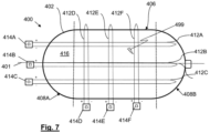
- FIG. 7 shows a longitudinal section through a fourth example organic composite storage tank 400 of the invention.
- the tank 400 has multiple metallic fibres such as 412A, 412B, 412C at different azimuthal positions within composite wall 402.
- Multiple metallic fibres such as 412D, 412E, 412F are provided at different axial positions.
- Electrical interrogators such as 414A-F therefore provide information on leaks over a range of azimuthal and axial positions.
- the azimuthal and axial positions of a particular leakage point such as 499 may be determined in the case of the tank 400; for example a leakage point 499 will give rise to increases in the electrical resistance of the metallic fibres 412A and 412F but will not affect the electrical resistances of the other metallic fibres 412B-E.
- the composite storage tanks 100, 200, 300, 400 provide for leakage to be detected within the composite walls of the tanks and also leakage resulting from defects in the polymer liners of the tanks 100, 200, 300, 400. Early warning of tank failure as a result of leakage is therefore provided for.
- the metallic fibres used provide a simple, robust and cheap mechanism for detecting leakage of hydrogen.
- metallic fibres in tanks 100, 200, 300, 400 extend either longitudinally or azimuthally, other embodiments may have off-axis metallic fibres.
- the metallic fibres comprised in a tank of the invention may be co-wound with a carbon-fibre tow during manufacture of the tank.
Landscapes
- Engineering & Computer Science (AREA)
- Mechanical Engineering (AREA)
- General Engineering & Computer Science (AREA)
- Sustainable Energy (AREA)
- Life Sciences & Earth Sciences (AREA)
- Sustainable Development (AREA)
- Aviation & Aerospace Engineering (AREA)
- Power Engineering (AREA)
- Transportation (AREA)
- Manufacturing & Machinery (AREA)
- Chemical & Material Sciences (AREA)
- Chemical Kinetics & Catalysis (AREA)
- Electrochemistry (AREA)
- General Chemical & Material Sciences (AREA)
- Filling Or Discharging Of Gas Storage Vessels (AREA)
Description
- The invention relates to composite gas storage tanks, particularly composite storage tanks for storing gaseous hydrogen at high pressure, for example 300 bar or greater.
- Organic matrix composite storage tanks for storing gaseous hydrogen at high pressure are of interest for hydrogen-powered transport applications (road, rail, aerospace) in which motive power is provided by proton-exchange membrane (PEM) fuel cells. Motive power in aerospace applications could alternatively or additionally be provided by one or more hydrogen-burning gas turbine engines. Organic matrix composite storage tanks are especially attractive for gaseous hydrogen storage in aerospace applications owing to their potential for achieving high gravimetric efficiencies of 10% or more. A so-called 'Type IV' tank comprises a carbon fibre composite wall, or shell, and a polymer liner (e.g. of polypropylene or polyethylene); a 'Type V' tank comprises a carbon fibre composite wall but does not have a polymer liner. The document
US2018274725 A1 discloses a composite gas storage tank. - When a composite storage tank is used to store hydrogen, the stored hydrogen tends to leak through the composite wall, and the liner if present, due to the very small size a hydrogen molecule (0.12 nm). The rate at which hydrogen leaks through the composite wall of a composite storage tank tends to increase over time with use of the tank because repeated charging and discharging cause microcracking and delamination within the composite shell. In order to reduce wastage of gaseous hydrogen fuel within the tank, it is desirable to be able to be able to find the rate at which hydrogen leaks from a tank during use and/or how much hydrogen has leaked from the tank over time. The tank can then be removed from service and replaced when the rate of leakage exceeds a threshold. Presently, composite tanks used in transport applications (typically automotive applications) provide no means for measuring the rate at which hydrogen leaks from a tank, or how much hydrogen has leaked over time, or for establishing an indication of the physical condition of the composite wall of the tank. The rate of leakage of a tank can only be found presently by taking the tank out of service and subjecting it to a known test, for example a helium leak test, vacuum test or hydrogen sensor (sniffing) test; in these tests the tank is removed from service even if its performance and condition are subsequently found to be satisfactory. Chemo-chromic indicators can provide an indication of the simple fact of leakage of gaseous hydrogen from a tank, but do not provide information on the current rate of leakage or historical leakage from the tank.
- According to a first aspect of the present invention, a composite storage tank for gaseous hydrogen comprises a composite wall enclosing a gas storage volume and a metallic fibre which is susceptible to embrittlement by hydrogen incorporated within the composite wall, wherein ends of the metallic fibre extend through the exterior surface of the composite wall. The extent of historical leakage of hydrogen from the tank, at the position of the metallic fibre, and its current physical condition, may be inferred from the electrical resistance of the metallic fibre.
- The composite wall may define a cylindrical portion of the tank and the metallic fibre may extend substantially parallel to the central longitudinal axis of the cylindrical portion of the tank. The condition of the cylindrical portion of the tank at a specific azimuthal position, and the historical leakage at that azimuthal position may then be inferred from the electrical resistance of the metallic fibre.
- The composite wall may include a plurality of metallic fibres each of which is susceptible to embrittlement by hydrogen and which extends substantially parallel to the central longitudinal axis of the cylindrical portion of the tank, the ends of each metallic fibre extending through the exterior surface of the composite wall, and each metallic fibre being located at a respective azimuthal position with respect to the central longitudinal axis of the cylindrical portion of the tank. The condition of the composite wall and the history of hydrogen leakage at each of a plurality of azimuthal positions within the composite shell may then be deduced from the electrical resistances of the fibres. The azimuthal position of a single leakage point may also be determined.
- The composite wall may define a cylindrical portion of the tank, the metallic fibre extending azimuthally at a single axial position with respect to the central longitudinal axis of the cylindrical portion of the tank, ends of the metallic fibre extending through the exterior surface of the composite wall, thereby allowing the condition of the tank and the history of hydrogen leakage at that axial position to be determined from the electrical resistance of the metallic fibre. The composite wall may include a plurality of metallic fibres each of which is susceptible to embrittlement by hydrogen and which extends azimuthally at a respective axial position with respect to the central longitudinal axis of the cylindrical portion of the tank, ends of each metallic fibre extending through the exterior surface of the composite wall. The condition and history of hydrogen leakage at each of a plurality of axial positions along the cylindrical portion of the tank may then be inferred from the electrical resistances of the fibres. The axial position of a single leak point may also be determined.
- The composite wall may define a cylindrical portion of the tank and include first and second sets of metallic fibres, each metallic fibre being susceptible to embrittlement by hydrogen, metallic fibres of the first set each extending substantially parallel to the central longitudinal axis of the cylindrical portion of the tank at a respective azimuthal position and metallic fibres of the second set each extending azimuthally at a respective axial position with respect to the central longitudinal axis of the cylindrical portion of the tank, ends of each metallic fibre extending through the exterior surface of the composite wall. The axial and azimuthal positions of a leak point may be determined from the electrical resistances of the metallic fibres.
- The composite wall may comprise an organic matrix composite.
- The composite storage tank may comprise a polymer liner in contact with the interior surface of the composite wall.
- At least one metallic fibre incorporated within the composite wall may be pre-stressed.
- A second aspect of the invention provides a composite storage tank system comprising a composite storage tank according to the first aspect and means for measuring the electrical resistance of the metallic fibre comprised in the composite wall of the composite storage tank.
- A third aspect of the invention provides an aircraft comprising a composite storage tank system according to the second aspect and at least one of a polymer electrolyte membrane (PEM) fuel cell and a hydrogen-burning gas turbine engine, the PEM fuel cell and/or the gas turbine engine being arranged to receive gaseous hydrogen from the composite storage tank of the composite storage tank system.
- Embodiments of the invention are described below by way of example only and with reference to the accompanying drawings in which:
- Figures 1A, 1B & 1C
- illustrate the process of embrittlement of metal in the presence of gaseous hydrogen;
- Figure 2
- shows a longitudinal section of a first example composite storage tank of the invention;
- Figure 3
- shows a transverse section through the tank of
Figure 2 ; - Figure 4
- illustrates variation in resistance of a metallic fibre comprised in the
Figure 2 tank; - Figures 5 & 6
- shows longitudinal sections though second and third composite storage tanks of the invention respectively; and
- Figure 7
- shows a longitudinal section of a fourth composite storage tank of the invention.
- Many metals embrittle on contact with hydrogen. Referring to
Figure 1A , at room temperature,hydrogen atoms 10 can be absorbed by carbon steel alloys & other metals. Hydrogen which is absorbed may be present in either atomic or molecular form. Given enough time, the hydrogen diffuses tometal grain boundaries 12 and formsbubbles 14 at these metal grain boundaries as shown inFigure 1B . These bubbles coalesce (Figure 1C ) to formlarger bubbles 16 which exert pressure on the corresponding metal grains. The pressure can increase to levels where the metal has reduced ductility and strength. - Hydrogen can enter and diffuse through steel even at room temperature. This can occur during various manufacturing and assembly operations or operational use - anywhere that metal comes into contact with atomic or molecular hydrogen. In common metal processing operations, there is a possibility of absorption of hydrogen during acid pickling and electroplating operations where hydrogen is evolved in chemical reactions. Hydrogen absorption can also occur when a component is in service if steel is exposed to acids or if corrosion of the steel occurs.
- As a result of hydrogen adsorption, hydrogen embrittlement occurs when a metal becomes brittle as a result of the introduction and diffusion of hydrogen into the metal.
- The degree of embrittlement is influenced both by the amount of hydrogen absorbed and the microstructure of the metal. Microstructures which bestow high strength, often monitored by hardness level, or having specific distributions of grain boundary particles or inclusions, can result in increased susceptibility to embrittlement. This phenomenon usually becomes significant when it leads to cracking. This happens when sufficient stress is applied to a hydrogen-embrittled object. Such stress states can be caused both by the presence of residual stresses, associated fabrication operations such as forming and welding, and applied service stresses. The severity of hydrogen embrittlement is a function of temperature: most metals are relatively immune to hydrogen embrittlement, above approximately 150°C.
- Intergranular cracking occurs when cracks form and grow along weakened grain boundaries in a metal. In the case of hydrogen embrittlement, the hydrogen bubbles at the grain boundaries of the alloy weaken the metal. There are three key requirements for failure due to hydrogen embrittlement:
- (i) a susceptible material;
- (ii) exposure to an environment that contains hydrogen; and
- (iii) the presence of tensile stress on the component.
- High-strength steels with tensile strength greater than about 145 ksi (1000 MPa) are the alloys most vulnerable to hydrogen embrittlement. Normally these are used as 'design rules' to avoid hydrogen embrittlement failures, however this invention uses the hydrogen embrittlement effect as the sensing element in a hydrogen tank.
- Referring to
Figures 2 and3 , a first example organiccomposite storage tank 100 of the invention comprises an organic matrixcomposite wall 102 defining astorage volume 116 for storing gaseous hydrogen. Thetank 100 comprises a polymer liner 118 (e.g. polypropylene or polyethylene) in contact with the internal surface of thecomposite wall 102, i.e. thetank 100 is a so-called "Type IV" tank. Thetank 100 comprises a cylindricalcentral section 106 formed integrally with domed orhemispherical end sections longitudinal axis 101. Ametallic coupling element 110 passes through thecomposite wall 102 and thepolymer liner 118 at theend section 108B and allows for filling and emptying of thetank 100. Ametallic fibre 112, which is selected specifically for its susceptibility to embrittlement in the presence of hydrogen, is incorporated into the lay up of thetank 100 and has a lead-outregion 113 extending beyond thetank 100 to anelectrical interrogation unit 114. Themetallic fibre 112 is located within thecomposite wall 102 at a radial position r greater than that of the polymer liner and extends longitudinally and substantially parallel to the centrallongitudinal axis 101 of thetank 100. The azimuthal position of themetallic fibre 112 over the cylindricalcentral section 106 is indicated by φ inFigure 3 . - The
metallic fibre 112 may be formed from any one of a range of metallic alloys which are susceptible to hydrogen embrittlement, for example high strength steel (typically greater than 32 Rockwell C hardness / UTS > 1000 MPa), stainless steel, titanium alloy (e.g. Ti 6-4), vanadium, vanadium alloys and nickel alloys. Preferably themetallic fibre 112 is thin (less than 100 µm in diameter) and laid into thecomposite wall 102 with a pre-stress applied to it in order to increase its stress sensitivity and its propensity to break during hydrogen embrittlement. During fabrication of thetank 100, themetallic fibre 112 is co-wound or laid-up into the structure of thetank 100 with a tensile pre-stress applied to it during lay-up and cure. -
Figure 4 shows the variation in resistance of themetallic fibre 112 as a function of time. During normal operation of thetank 100, themetallic fibre 112 exhibits no change in electrical resistance as measured by theinterrogator 114. This corresponds toportion 1 of the graph shown inFigure 4 . If thepolymer liner 118 is defective, hydrogen will diffuse through thecomposite wall 102 and interact with themetallic fibre 112, embrittling it. The rate at which hydrogen diffuses through thecomposite wall 102 depends on the extent of any cracking or delamination in thecomposite wall 102. - This diffusion results in an increase in electrical resistance of the
metallic fibre 112, as indicated byportion 2 of the graph ofFigure 4 . Strain cycles on thetank 100 resulting from repeated charging/discharging cycles, combined with pre-stress in themetallic fibre 112, will eventually cause themetallic fibre 112 to undergo brittle failure, indicated byportion 3 of the graph inFigure 4 . Theelectrical interrogator 114 will detect this as an open circuit (infinite) resistance. The resistance of themetallic fibre 112 therefore represents an integrated history of leakage through thepolymer liner 118 and thecomposite wall 102. -
Figure 5 shows a longitudinal section though a second example organiccomposite storage tank 200 of the invention. Parts of thetank 200 which correspond to parts of thetank 100 ofFigures 2 and3 are labelled with reference signs differing by 100 from those labelling the corresponding parts inFigures 2 and3 . Thetank 200 has multiple metallic fibres such as 212A, 212B, 212C at different azimuthal positions within thecomposite wall 202 of thetank 200. Electrical interrogators such as 214A, 214B, 214C therefore provide information on leaks over a range of azimuthal positions within thecomposite wall 202. The azimuthal position of a particular leakage point may be determined. -
Figure 6 shows a longitudinal section through a third example organiccomposite storage tank 300 of the invention. Parts of thetank 300 which correspond to parts of thetank 100 ofFigures 2 and3 are labelled with reference signs differing by 200 from those labelling the corresponding parts inFigures 2 and3 . Thetank 300 has multiple metallic fibres such as 312A, 312B, 312C at different axial positions within thecomposite wall 202 of thetank 200. Electrical interrogators such as 314A, 314B, 314C therefore provide information on leaks over a range of axial positions within thecomposite wall 202. The axial position of a particular leakage point may be determined. -
Figure 7 shows a longitudinal section through a fourth example organiccomposite storage tank 400 of the invention. Parts of thetank 400 which correspond to parts of thetank 100 ofFigures 2 and3 are labelled with reference signs differing by 300 from those labelling the corresponding parts inFigures 2 and3 . Thetank 400 has multiple metallic fibres such as 412A, 412B, 412C at different azimuthal positions withincomposite wall 402. Multiple metallic fibres such as 412D, 412E, 412F are provided at different axial positions. Electrical interrogators such as 414A-F therefore provide information on leaks over a range of azimuthal and axial positions. The azimuthal and axial positions of a particular leakage point such as 499 may be determined in the case of thetank 400; for example aleakage point 499 will give rise to increases in the electrical resistance of themetallic fibres metallic fibres 412B-E. - The
composite storage tanks tanks - Although metallic fibres in
tanks - The metallic fibres comprised in a tank of the invention may be co-wound with a carbon-fibre tow during manufacture of the tank.
Claims (11)
- A composite storage tank (100; 200; 300; 400) for gaseous hydrogen, the tank comprising a composite wall (102; 202; 302; 402) enclosing a gas storage volume (116; 216; 316; 416), characterised in having a metallic fibre (112; 212A; 312A; 412A) which is susceptible to embrittlement by hydrogen incorporated within the composite wall, wherein ends of the metallic fibre extend through the exterior surface of the composite wall.
- A composite storage tank (100; 200; 400) according to claim 1 wherein the composite wall (102; 202; 402) defines a cylindrical portion (106; 206; 406) of the tank and the metallic fibre (112; 212A; 412A) extends substantially parallel to the central longitudinal axis (101; 201; 401) of the cylindrical portion of the tank.
- A composite storage tank (200; 400) according to claim 2 wherein the composite wall (202; 402) includes a plurality of metallic fibres (212A-C; 412A-C) each of which is susceptible to embrittlement by hydrogen and which extends substantially parallel to the central longitudinal axis (201; 401) of the cylindrical portion of the tank, the ends of each metallic fibre extending through the exterior surface of the composite wall, and wherein each metallic fibre is located at a respective azimuthal position with respect to the central longitudinal axis of the cylindrical portion of the tank.
- A composite storage tank (300; 400) according to claim 1 wherein the composite wall defines a cylindrical portion (306; 406) of the tank, the metallic fibre (312A; 412D) extends azimuthally at a single axial position with respect to the central longitudinal axis (301; 401) of the cylindrical portion of the tank and the ends of the metallic fibre extend through the exterior surface of the composite wall.
- A composite storage tank (300; 400) according to claim 4 wherein the composite wall (302; 402) includes a plurality of metallic fibres (312A-C; 412D-F) each of which is susceptible to embrittlement by hydrogen and which extends azimuthally at a respective axial position with respect to the central longitudinal axis (301; 401) of the cylindrical portion of the tank, and wherein the ends of each metallic fibre extend through the exterior surface of the composite wall.
- A composite storage tank (400) according to claim 1 wherein the composite wall (402) defines a cylindrical portion (406) of the tank and includes first (412A-C) and second (412D-F) sets of metallic fibres each metallic fibre being susceptible to embrittlement by hydrogen, metallic fibres (412A-C) of the first set each extending substantially parallel to the central longitudinal axis of the cylindrical portion of the tank at a respective azimuthal position and metallic fibres (412D-F) of the second set each extending azimuthally at a respective axial position with respect to the central longitudinal axis (401) of the cylindrical portion of the tank, and wherein the ends of each metallic fibre extend through the exterior surface of the composite wall.
- A composite storage tank according to any preceding claim wherein the composite wall comprises an organic matrix composite.
- A composite storage tank according to any preceding claim wherein the tank comprises a polymer liner in contact with the interior surface of the composite wall.
- A composite storage tank according to any preceding claim wherein at least one metallic fibre incorporated within the composite wall is pre-stressed.
- A composite storage tank system comprising a composite storage tank according to any preceding claim and means for measuring the electrical resistance of the or each metallic fibre.
- An aircraft comprising a composite storage tank system according to claim 10 and at least one of a polymer electrolyte membrane (PEM) fuel cell and a hydrogen-burning gas turbine engine, the PEM fuel cell and/or the gas turbine engine being arranged to receive gaseous hydrogen from the composite storage tank of the composite storage tank system.
Applications Claiming Priority (1)
| Application Number | Priority Date | Filing Date | Title |
|---|---|---|---|
| GBGB2013873.1A GB202013873D0 (en) | 2020-09-03 | 2020-09-03 | Composite storage tank for gaseous hydrogen |
Publications (2)
| Publication Number | Publication Date |
|---|---|
| EP3964746A1 EP3964746A1 (en) | 2022-03-09 |
| EP3964746B1 true EP3964746B1 (en) | 2023-11-08 |
Family
ID=72841316
Family Applications (1)
| Application Number | Title | Priority Date | Filing Date |
|---|---|---|---|
| EP21189254.2A Active EP3964746B1 (en) | 2020-09-03 | 2021-08-03 | Composite storage tank for gaseous hydrogen |
Country Status (3)
| Country | Link |
|---|---|
| US (1) | US11655939B2 (en) |
| EP (1) | EP3964746B1 (en) |
| GB (1) | GB202013873D0 (en) |
Family Cites Families (12)
| Publication number | Priority date | Publication date | Assignee | Title |
|---|---|---|---|---|
| US2273736A (en) * | 1938-12-05 | 1942-02-17 | Raymond Gwynne | Method of making pressure vessles and the like |
| US5816426A (en) * | 1994-08-31 | 1998-10-06 | Sharp; Bruce R. | Double walled storage tank systems |
| US6382232B1 (en) * | 2001-03-09 | 2002-05-07 | Dynetek Industries Ltd. | Remote triggering system and retrofit kit for thermal-pressure relief devices |
| US7254983B2 (en) | 2001-10-16 | 2007-08-14 | Hera Usa Inc. | Fuel gauge for hydrogen storage media |
| DE10154145C1 (en) | 2001-11-03 | 2003-06-26 | Deutsch Zentr Luft & Raumfahrt | Composite pressurized gas container monitoring method uses resistance wire for monitoring container peripheral expansion |
| US8220130B2 (en) * | 2007-07-25 | 2012-07-17 | Plasteel International, Inc. | Method for manufacturing an underground storage tank for flammable and combustible liquids |
| US9266642B2 (en) * | 2008-09-23 | 2016-02-23 | WireTough Cylinders, LLC | Steel wrapped pressure vessel |
| DE202009008026U1 (en) | 2009-06-09 | 2010-10-28 | Funck, Herbert | Pressure vessel with fiber reinforcement |
| DE102010043645B4 (en) * | 2010-11-09 | 2012-12-06 | Deutsches Zentrum für Luft- und Raumfahrt e.V. | Pressure tank composite |
| FR2976045A1 (en) * | 2011-06-06 | 2012-12-07 | Air Liquide | PRESSURIZED FLUID RESERVOIR |
| DE102014003587A1 (en) * | 2014-03-11 | 2015-09-17 | GM Global Technology Operations LLC (n. d. Gesetzen des Staates Delaware) | Gas tank, motor vehicle |
| KR102298962B1 (en) * | 2017-03-24 | 2021-09-06 | 현대자동차주식회사 | High-pressure tank for enabling radation of heat and discharging permeated gas from thereof and the method for the same |
-
2020
- 2020-09-03 GB GBGB2013873.1A patent/GB202013873D0/en not_active Ceased
-
2021
- 2021-08-03 EP EP21189254.2A patent/EP3964746B1/en active Active
- 2021-08-16 US US17/403,090 patent/US11655939B2/en active Active
Also Published As
| Publication number | Publication date |
|---|---|
| US20220065398A1 (en) | 2022-03-03 |
| GB202013873D0 (en) | 2020-10-21 |
| EP3964746A1 (en) | 2022-03-09 |
| US11655939B2 (en) | 2023-05-23 |
Similar Documents
| Publication | Publication Date | Title |
|---|---|---|
| Okonkwo et al. | A focused review of the hydrogen storage tank embrittlement mechanism process | |
| Hua et al. | Hydrogen-enhanced fatigue life analysis of Cr–Mo steel high-pressure vessels | |
| Idarraga-Trujillo et al. | Assessment at CEA of coated nuclear fuel cladding for LWRs with increased margins in LOCA and beyond LOCA conditions | |
| Brachet et al. | Behavior of cr-coated m5 claddings during and after high temperature steam oxidationfrom 800c up to 1500c | |
| CN103969299A (en) | Method For Online Detection Of Liner Buckling In A Storage System For Pressurized Gas | |
| Hu | Heat-resistant steels, microstructure evolution and life assessment in power plants | |
| KR102805468B1 (en) | Inspection apparatus for pressure vessel and monitoring sensor | |
| EP3964746B1 (en) | Composite storage tank for gaseous hydrogen | |
| Bind et al. | Effect of deuterium content on fracture toughness of Zr-2.5 Nb pressure tube material in the temperature range of ambient to 300° C | |
| Raj et al. | Meeting the challenges related to material issues in chemical industries | |
| EP3974701B1 (en) | Composite storage tank system for gaseous hydrogen | |
| Viswanathan et al. | Life-assessment technology for power-plant components | |
| Celaya-García et al. | Manufacture, Modeling, and Testing of Wire-Reinforced Metallic Pressure Vessel Prototypes | |
| Guowei et al. | Application and research of twin-electrode TIG cladding process on reactor pressure vessels manufacturing | |
| Fukuyama et al. | Development of new material testing apparatus in high-pressure hydrogen and evaluation of hydrogen gas embrittlement of metals | |
| Titran | Long-time creep behavior of Nb-1Zr alloy containing carbon | |
| Faddoul | Structural considerations in design of lightweight glass-fiber composite pressure vessels | |
| Andresen | SCC of Alloy 825, High Cr Alloy 800 and Other Interesting Alloys in High Temperature Water | |
| Raskop et al. | Innovative Quenched and Tempered Steel for the Production of Components for Hydrogen Drives | |
| Hu et al. | Damage and residual life assessment of bends for X20CrMoV12. 1 main steam pipe after long-term service | |
| Vieira et al. | H2 high pressure on-board storage considering safety issues | |
| Radhika et al. | Design, Fabrication and Testing of Composite Overwrapped Pressure Vessel for CNG Storage | |
| Lanzo et al. | Structural integrity assessment of type IV hydrogen pressure vessels: Drop testing and fatigue damage modelling | |
| Ferro | Spokane, WA, USA | |
| Le Saux | Contribution to the study of the response of heterogeneous materials subjected to environmental and mechanical loading |
Legal Events
| Date | Code | Title | Description |
|---|---|---|---|
| PUAI | Public reference made under article 153(3) epc to a published international application that has entered the european phase |
Free format text: ORIGINAL CODE: 0009012 |
|
| STAA | Information on the status of an ep patent application or granted ep patent |
Free format text: STATUS: THE APPLICATION HAS BEEN PUBLISHED |
|
| AK | Designated contracting states |
Kind code of ref document: A1 Designated state(s): AL AT BE BG CH CY CZ DE DK EE ES FI FR GB GR HR HU IE IS IT LI LT LU LV MC MK MT NL NO PL PT RO RS SE SI SK SM TR |
|
| STAA | Information on the status of an ep patent application or granted ep patent |
Free format text: STATUS: REQUEST FOR EXAMINATION WAS MADE |
|
| 17P | Request for examination filed |
Effective date: 20220701 |
|
| RBV | Designated contracting states (corrected) |
Designated state(s): AL AT BE BG CH CY CZ DE DK EE ES FI FR GB GR HR HU IE IS IT LI LT LU LV MC MK MT NL NO PL PT RO RS SE SI SK SM TR |
|
| GRAP | Despatch of communication of intention to grant a patent |
Free format text: ORIGINAL CODE: EPIDOSNIGR1 |
|
| STAA | Information on the status of an ep patent application or granted ep patent |
Free format text: STATUS: GRANT OF PATENT IS INTENDED |
|
| GRAS | Grant fee paid |
Free format text: ORIGINAL CODE: EPIDOSNIGR3 |
|
| GRAA | (expected) grant |
Free format text: ORIGINAL CODE: 0009210 |
|
| STAA | Information on the status of an ep patent application or granted ep patent |
Free format text: STATUS: THE PATENT HAS BEEN GRANTED |
|
| INTG | Intention to grant announced |
Effective date: 20230922 |
|
| AK | Designated contracting states |
Kind code of ref document: B1 Designated state(s): AL AT BE BG CH CY CZ DE DK EE ES FI FR GB GR HR HU IE IS IT LI LT LU LV MC MK MT NL NO PL PT RO RS SE SI SK SM TR |
|
| P01 | Opt-out of the competence of the unified patent court (upc) registered |
Effective date: 20231002 |
|
| REG | Reference to a national code |
Ref country code: GB Ref legal event code: FG4D |
|
| REG | Reference to a national code |
Ref country code: CH Ref legal event code: EP |
|
| REG | Reference to a national code |
Ref country code: DE Ref legal event code: R096 Ref document number: 602021006591 Country of ref document: DE |
|
| REG | Reference to a national code |
Ref country code: IE Ref legal event code: FG4D |
|
| REG | Reference to a national code |
Ref country code: LT Ref legal event code: MG9D |
|
| REG | Reference to a national code |
Ref country code: NL Ref legal event code: MP Effective date: 20231108 |
|
| PG25 | Lapsed in a contracting state [announced via postgrant information from national office to epo] |
Ref country code: GR Free format text: LAPSE BECAUSE OF FAILURE TO SUBMIT A TRANSLATION OF THE DESCRIPTION OR TO PAY THE FEE WITHIN THE PRESCRIBED TIME-LIMIT Effective date: 20240209 |
|
| PG25 | Lapsed in a contracting state [announced via postgrant information from national office to epo] |
Ref country code: IS Free format text: LAPSE BECAUSE OF FAILURE TO SUBMIT A TRANSLATION OF THE DESCRIPTION OR TO PAY THE FEE WITHIN THE PRESCRIBED TIME-LIMIT Effective date: 20240308 |
|
| PG25 | Lapsed in a contracting state [announced via postgrant information from national office to epo] |
Ref country code: LT Free format text: LAPSE BECAUSE OF FAILURE TO SUBMIT A TRANSLATION OF THE DESCRIPTION OR TO PAY THE FEE WITHIN THE PRESCRIBED TIME-LIMIT Effective date: 20231108 |
|
| REG | Reference to a national code |
Ref country code: AT Ref legal event code: MK05 Ref document number: 1629892 Country of ref document: AT Kind code of ref document: T Effective date: 20231108 |
|
| PG25 | Lapsed in a contracting state [announced via postgrant information from national office to epo] |
Ref country code: NL Free format text: LAPSE BECAUSE OF FAILURE TO SUBMIT A TRANSLATION OF THE DESCRIPTION OR TO PAY THE FEE WITHIN THE PRESCRIBED TIME-LIMIT Effective date: 20231108 |
|
| PG25 | Lapsed in a contracting state [announced via postgrant information from national office to epo] |
Ref country code: AT Free format text: LAPSE BECAUSE OF FAILURE TO SUBMIT A TRANSLATION OF THE DESCRIPTION OR TO PAY THE FEE WITHIN THE PRESCRIBED TIME-LIMIT Effective date: 20231108 |
|
| PG25 | Lapsed in a contracting state [announced via postgrant information from national office to epo] |
Ref country code: ES Free format text: LAPSE BECAUSE OF FAILURE TO SUBMIT A TRANSLATION OF THE DESCRIPTION OR TO PAY THE FEE WITHIN THE PRESCRIBED TIME-LIMIT Effective date: 20231108 |
|
| PG25 | Lapsed in a contracting state [announced via postgrant information from national office to epo] |
Ref country code: NL Free format text: LAPSE BECAUSE OF FAILURE TO SUBMIT A TRANSLATION OF THE DESCRIPTION OR TO PAY THE FEE WITHIN THE PRESCRIBED TIME-LIMIT Effective date: 20231108 Ref country code: LT Free format text: LAPSE BECAUSE OF FAILURE TO SUBMIT A TRANSLATION OF THE DESCRIPTION OR TO PAY THE FEE WITHIN THE PRESCRIBED TIME-LIMIT Effective date: 20231108 Ref country code: IS Free format text: LAPSE BECAUSE OF FAILURE TO SUBMIT A TRANSLATION OF THE DESCRIPTION OR TO PAY THE FEE WITHIN THE PRESCRIBED TIME-LIMIT Effective date: 20240308 Ref country code: GR Free format text: LAPSE BECAUSE OF FAILURE TO SUBMIT A TRANSLATION OF THE DESCRIPTION OR TO PAY THE FEE WITHIN THE PRESCRIBED TIME-LIMIT Effective date: 20240209 Ref country code: ES Free format text: LAPSE BECAUSE OF FAILURE TO SUBMIT A TRANSLATION OF THE DESCRIPTION OR TO PAY THE FEE WITHIN THE PRESCRIBED TIME-LIMIT Effective date: 20231108 Ref country code: BG Free format text: LAPSE BECAUSE OF FAILURE TO SUBMIT A TRANSLATION OF THE DESCRIPTION OR TO PAY THE FEE WITHIN THE PRESCRIBED TIME-LIMIT Effective date: 20240208 Ref country code: AT Free format text: LAPSE BECAUSE OF FAILURE TO SUBMIT A TRANSLATION OF THE DESCRIPTION OR TO PAY THE FEE WITHIN THE PRESCRIBED TIME-LIMIT Effective date: 20231108 Ref country code: PT Free format text: LAPSE BECAUSE OF FAILURE TO SUBMIT A TRANSLATION OF THE DESCRIPTION OR TO PAY THE FEE WITHIN THE PRESCRIBED TIME-LIMIT Effective date: 20240308 |
|
| PG25 | Lapsed in a contracting state [announced via postgrant information from national office to epo] |
Ref country code: SE Free format text: LAPSE BECAUSE OF FAILURE TO SUBMIT A TRANSLATION OF THE DESCRIPTION OR TO PAY THE FEE WITHIN THE PRESCRIBED TIME-LIMIT Effective date: 20231108 Ref country code: RS Free format text: LAPSE BECAUSE OF FAILURE TO SUBMIT A TRANSLATION OF THE DESCRIPTION OR TO PAY THE FEE WITHIN THE PRESCRIBED TIME-LIMIT Effective date: 20231108 Ref country code: PL Free format text: LAPSE BECAUSE OF FAILURE TO SUBMIT A TRANSLATION OF THE DESCRIPTION OR TO PAY THE FEE WITHIN THE PRESCRIBED TIME-LIMIT Effective date: 20231108 Ref country code: NO Free format text: LAPSE BECAUSE OF FAILURE TO SUBMIT A TRANSLATION OF THE DESCRIPTION OR TO PAY THE FEE WITHIN THE PRESCRIBED TIME-LIMIT Effective date: 20240208 Ref country code: LV Free format text: LAPSE BECAUSE OF FAILURE TO SUBMIT A TRANSLATION OF THE DESCRIPTION OR TO PAY THE FEE WITHIN THE PRESCRIBED TIME-LIMIT Effective date: 20231108 Ref country code: HR Free format text: LAPSE BECAUSE OF FAILURE TO SUBMIT A TRANSLATION OF THE DESCRIPTION OR TO PAY THE FEE WITHIN THE PRESCRIBED TIME-LIMIT Effective date: 20231108 |
|
| PG25 | Lapsed in a contracting state [announced via postgrant information from national office to epo] |
Ref country code: DK Free format text: LAPSE BECAUSE OF FAILURE TO SUBMIT A TRANSLATION OF THE DESCRIPTION OR TO PAY THE FEE WITHIN THE PRESCRIBED TIME-LIMIT Effective date: 20231108 |
|
| PG25 | Lapsed in a contracting state [announced via postgrant information from national office to epo] |
Ref country code: CZ Free format text: LAPSE BECAUSE OF FAILURE TO SUBMIT A TRANSLATION OF THE DESCRIPTION OR TO PAY THE FEE WITHIN THE PRESCRIBED TIME-LIMIT Effective date: 20231108 |
|
| PG25 | Lapsed in a contracting state [announced via postgrant information from national office to epo] |
Ref country code: SK Free format text: LAPSE BECAUSE OF FAILURE TO SUBMIT A TRANSLATION OF THE DESCRIPTION OR TO PAY THE FEE WITHIN THE PRESCRIBED TIME-LIMIT Effective date: 20231108 |
|
| PG25 | Lapsed in a contracting state [announced via postgrant information from national office to epo] |
Ref country code: SM Free format text: LAPSE BECAUSE OF FAILURE TO SUBMIT A TRANSLATION OF THE DESCRIPTION OR TO PAY THE FEE WITHIN THE PRESCRIBED TIME-LIMIT Effective date: 20231108 Ref country code: SK Free format text: LAPSE BECAUSE OF FAILURE TO SUBMIT A TRANSLATION OF THE DESCRIPTION OR TO PAY THE FEE WITHIN THE PRESCRIBED TIME-LIMIT Effective date: 20231108 Ref country code: RO Free format text: LAPSE BECAUSE OF FAILURE TO SUBMIT A TRANSLATION OF THE DESCRIPTION OR TO PAY THE FEE WITHIN THE PRESCRIBED TIME-LIMIT Effective date: 20231108 Ref country code: IT Free format text: LAPSE BECAUSE OF FAILURE TO SUBMIT A TRANSLATION OF THE DESCRIPTION OR TO PAY THE FEE WITHIN THE PRESCRIBED TIME-LIMIT Effective date: 20231108 Ref country code: EE Free format text: LAPSE BECAUSE OF FAILURE TO SUBMIT A TRANSLATION OF THE DESCRIPTION OR TO PAY THE FEE WITHIN THE PRESCRIBED TIME-LIMIT Effective date: 20231108 Ref country code: DK Free format text: LAPSE BECAUSE OF FAILURE TO SUBMIT A TRANSLATION OF THE DESCRIPTION OR TO PAY THE FEE WITHIN THE PRESCRIBED TIME-LIMIT Effective date: 20231108 Ref country code: CZ Free format text: LAPSE BECAUSE OF FAILURE TO SUBMIT A TRANSLATION OF THE DESCRIPTION OR TO PAY THE FEE WITHIN THE PRESCRIBED TIME-LIMIT Effective date: 20231108 |
|
| REG | Reference to a national code |
Ref country code: DE Ref legal event code: R097 Ref document number: 602021006591 Country of ref document: DE |
|
| PLBE | No opposition filed within time limit |
Free format text: ORIGINAL CODE: 0009261 |
|
| STAA | Information on the status of an ep patent application or granted ep patent |
Free format text: STATUS: NO OPPOSITION FILED WITHIN TIME LIMIT |
|
| 26N | No opposition filed |
Effective date: 20240809 |
|
| PG25 | Lapsed in a contracting state [announced via postgrant information from national office to epo] |
Ref country code: SI Free format text: LAPSE BECAUSE OF FAILURE TO SUBMIT A TRANSLATION OF THE DESCRIPTION OR TO PAY THE FEE WITHIN THE PRESCRIBED TIME-LIMIT Effective date: 20231108 |
|
| PG25 | Lapsed in a contracting state [announced via postgrant information from national office to epo] |
Ref country code: SI Free format text: LAPSE BECAUSE OF FAILURE TO SUBMIT A TRANSLATION OF THE DESCRIPTION OR TO PAY THE FEE WITHIN THE PRESCRIBED TIME-LIMIT Effective date: 20231108 |
|
| REG | Reference to a national code |
Ref country code: CH Ref legal event code: PL |
|
| PG25 | Lapsed in a contracting state [announced via postgrant information from national office to epo] |
Ref country code: LU Free format text: LAPSE BECAUSE OF NON-PAYMENT OF DUE FEES Effective date: 20240803 |
|
| PG25 | Lapsed in a contracting state [announced via postgrant information from national office to epo] |
Ref country code: CH Free format text: LAPSE BECAUSE OF NON-PAYMENT OF DUE FEES Effective date: 20240831 Ref country code: MC Free format text: LAPSE BECAUSE OF FAILURE TO SUBMIT A TRANSLATION OF THE DESCRIPTION OR TO PAY THE FEE WITHIN THE PRESCRIBED TIME-LIMIT Effective date: 20231108 |
|
| REG | Reference to a national code |
Ref country code: BE Ref legal event code: MM Effective date: 20240831 |
|
| PG25 | Lapsed in a contracting state [announced via postgrant information from national office to epo] |
Ref country code: BE Free format text: LAPSE BECAUSE OF NON-PAYMENT OF DUE FEES Effective date: 20240831 |
|
| PG25 | Lapsed in a contracting state [announced via postgrant information from national office to epo] |
Ref country code: IE Free format text: LAPSE BECAUSE OF NON-PAYMENT OF DUE FEES Effective date: 20240803 |
|
| PG25 | Lapsed in a contracting state [announced via postgrant information from national office to epo] |
Ref country code: FI Free format text: LAPSE BECAUSE OF FAILURE TO SUBMIT A TRANSLATION OF THE DESCRIPTION OR TO PAY THE FEE WITHIN THE PRESCRIBED TIME-LIMIT Effective date: 20231108 |
|
| PGFP | Annual fee paid to national office [announced via postgrant information from national office to epo] |
Ref country code: DE Payment date: 20250827 Year of fee payment: 5 |
|
| PGFP | Annual fee paid to national office [announced via postgrant information from national office to epo] |
Ref country code: GB Payment date: 20250826 Year of fee payment: 5 |
|
| PGFP | Annual fee paid to national office [announced via postgrant information from national office to epo] |
Ref country code: FR Payment date: 20250825 Year of fee payment: 5 |
|
| PG25 | Lapsed in a contracting state [announced via postgrant information from national office to epo] |
Ref country code: CY Free format text: LAPSE BECAUSE OF FAILURE TO SUBMIT A TRANSLATION OF THE DESCRIPTION OR TO PAY THE FEE WITHIN THE PRESCRIBED TIME-LIMIT; INVALID AB INITIO Effective date: 20210803 |
|
| PG25 | Lapsed in a contracting state [announced via postgrant information from national office to epo] |
Ref country code: HU Free format text: LAPSE BECAUSE OF FAILURE TO SUBMIT A TRANSLATION OF THE DESCRIPTION OR TO PAY THE FEE WITHIN THE PRESCRIBED TIME-LIMIT; INVALID AB INITIO Effective date: 20210803 |