EP3964717A1 - Multiphase subsea pressure exchanger - Google Patents
Multiphase subsea pressure exchanger Download PDFInfo
- Publication number
- EP3964717A1 EP3964717A1 EP20194256.2A EP20194256A EP3964717A1 EP 3964717 A1 EP3964717 A1 EP 3964717A1 EP 20194256 A EP20194256 A EP 20194256A EP 3964717 A1 EP3964717 A1 EP 3964717A1
- Authority
- EP
- European Patent Office
- Prior art keywords
- pump
- pressure
- fluid
- driving fluid
- low pressure
- Prior art date
- Legal status (The legal status is an assumption and is not a legal conclusion. Google has not performed a legal analysis and makes no representation as to the accuracy of the status listed.)
- Withdrawn
Links
- 239000012530 fluid Substances 0.000 claims abstract description 264
- 238000000034 method Methods 0.000 claims abstract description 105
- 230000008569 process Effects 0.000 claims abstract description 105
- 238000007599 discharging Methods 0.000 claims abstract description 7
- XLYOFNOQVPJJNP-UHFFFAOYSA-N water Substances O XLYOFNOQVPJJNP-UHFFFAOYSA-N 0.000 claims description 18
- 239000003921 oil Substances 0.000 claims description 17
- 229930195733 hydrocarbon Natural products 0.000 claims description 12
- 150000002430 hydrocarbons Chemical class 0.000 claims description 12
- 239000004215 Carbon black (E152) Substances 0.000 claims description 11
- 239000010779 crude oil Substances 0.000 claims description 7
- 239000007788 liquid Substances 0.000 claims description 7
- 238000009434 installation Methods 0.000 claims description 4
- 239000007789 gas Substances 0.000 description 29
- 238000013461 design Methods 0.000 description 9
- 230000005484 gravity Effects 0.000 description 8
- 239000013535 sea water Substances 0.000 description 8
- 238000004891 communication Methods 0.000 description 7
- 238000012546 transfer Methods 0.000 description 7
- 239000007792 gaseous phase Substances 0.000 description 6
- 238000004519 manufacturing process Methods 0.000 description 6
- VNWKTOKETHGBQD-UHFFFAOYSA-N methane Chemical compound C VNWKTOKETHGBQD-UHFFFAOYSA-N 0.000 description 6
- 230000008901 benefit Effects 0.000 description 5
- 239000007791 liquid phase Substances 0.000 description 5
- 239000000203 mixture Substances 0.000 description 5
- 239000012071 phase Substances 0.000 description 5
- 238000012545 processing Methods 0.000 description 5
- 238000013016 damping Methods 0.000 description 4
- 238000007667 floating Methods 0.000 description 4
- 239000007790 solid phase Substances 0.000 description 4
- 238000003860 storage Methods 0.000 description 4
- CURLTUGMZLYLDI-UHFFFAOYSA-N Carbon dioxide Chemical compound O=C=O CURLTUGMZLYLDI-UHFFFAOYSA-N 0.000 description 3
- 230000009471 action Effects 0.000 description 3
- 230000004323 axial length Effects 0.000 description 3
- 230000007423 decrease Effects 0.000 description 3
- 238000005086 pumping Methods 0.000 description 3
- 239000001569 carbon dioxide Substances 0.000 description 2
- 229910002092 carbon dioxide Inorganic materials 0.000 description 2
- 238000001816 cooling Methods 0.000 description 2
- 230000008878 coupling Effects 0.000 description 2
- 238000010168 coupling process Methods 0.000 description 2
- 238000005859 coupling reaction Methods 0.000 description 2
- 230000000694 effects Effects 0.000 description 2
- 238000005516 engineering process Methods 0.000 description 2
- 239000003345 natural gas Substances 0.000 description 2
- 238000007789 sealing Methods 0.000 description 2
- 239000007787 solid Substances 0.000 description 2
- 230000033228 biological regulation Effects 0.000 description 1
- 230000008859 change Effects 0.000 description 1
- 230000006835 compression Effects 0.000 description 1
- 238000007906 compression Methods 0.000 description 1
- 230000001419 dependent effect Effects 0.000 description 1
- 230000005284 excitation Effects 0.000 description 1
- 230000009334 lomakin effect Effects 0.000 description 1
- 230000001050 lubricating effect Effects 0.000 description 1
- 238000005461 lubrication Methods 0.000 description 1
- 238000012423 maintenance Methods 0.000 description 1
- 238000012986 modification Methods 0.000 description 1
- 230000004048 modification Effects 0.000 description 1
- 239000002245 particle Substances 0.000 description 1
- 238000005191 phase separation Methods 0.000 description 1
- 239000013558 reference substance Substances 0.000 description 1
- 230000003068 static effect Effects 0.000 description 1
- 230000035899 viability Effects 0.000 description 1
Images



Classifications
-
- F—MECHANICAL ENGINEERING; LIGHTING; HEATING; WEAPONS; BLASTING
- F04—POSITIVE - DISPLACEMENT MACHINES FOR LIQUIDS; PUMPS FOR LIQUIDS OR ELASTIC FLUIDS
- F04D—NON-POSITIVE-DISPLACEMENT PUMPS
- F04D31/00—Pumping liquids and elastic fluids at the same time
-
- F—MECHANICAL ENGINEERING; LIGHTING; HEATING; WEAPONS; BLASTING
- F04—POSITIVE - DISPLACEMENT MACHINES FOR LIQUIDS; PUMPS FOR LIQUIDS OR ELASTIC FLUIDS
- F04F—PUMPING OF FLUID BY DIRECT CONTACT OF ANOTHER FLUID OR BY USING INERTIA OF FLUID TO BE PUMPED; SIPHONS
- F04F13/00—Pressure exchangers
Definitions
- the invention relates to a pump system for conveying a multiphase process fluid from a source for the multiphase process fluid to a delivery location, wherein the pump system comprises a rotodynamic pump and a pressure exchanger unit.
- a well-known example of a multiphase process fluid is a combination comprising crude oil, water and hydrocarbon gas.
- hydrocarbon containing process fluids for example for extracting the crude oil from the oil field or for transportation of the oil/gas through pipelines or within refineries.
- One of the challenges regarding conveying or pumping multiphase process fluids is the fact that in many applications the composition of the multiphase process fluid is strongly varying during operation of the pump(s). For example, during exploitation of an oil field the ratio of the gaseous phase (e.g. natural gas) and the liquid phase (e.g. crude oil) is strongly varying. These variations may occur very suddenly.
- the ratio of the gaseous phase in the multiphase process fluid is commonly described by the dimensionless gas volume fraction (GVF) designating the volume ratio of the gas in the multiphase process fluid.
- VVF dimensionless gas volume fraction
- multiphase pumps are known, which can handle gas volume fraction from 0% to 100%.
- the multiphase pump comprises a plurality of helico-axial impellers for pumping the process fluid.
- topside applications i.e. on or above the water surface
- onshore applications it is often necessary to transport the multiphase process fluid over long distances in the piping connecting the multiphase pump at or near the well with the processing facility.
- Rotodynamicmultiphase pumps which can operate under constantly changing operating conditions and can handle multiphase process fluids with a GVF ranging from 0 to 100%, are typically configured as multistage pumps with a plurality of helico-axial impellers arranged one after another which results in a long rotor of the pump.
- the long rotor is supported by hydrodynamic bearings. It is well known that, depending on the gas content in the multiphase process fluid, the (subsea) multiphase pump can exhibit a challenging rotordynamic behavior. This is linked to several factors, including long rotors, complex internal flow regimes due to phase separation and reduced rotordynamic damping, especially at high gas contents. Furthermore, in a vertical configuration, i.e.
- the pump shaft extends in the vertical direction (direction of gravity), there is no force or nearly no force in the bearing plane of the radial bearings, which pulls the shaft in one specific direction. There is nearly no load generated on the radial bearings by the weight of the pump shaft and the impeller(s) and there is no defined direction of the static load. This means that the pump shaft does not have a preferred position in the bearing clearance of the radial bearing(s). Therefore, a small excitation is enough to make the pump shaft move within the bearing clearance.
- a multiphase pump with helico-axial impellers is limited regarding the pressure increase generated by the pump. Therefore the multiphase pump may not provide very high boosting pressures, in particular if the multiphase process fluid contains a predominant gaseous phase, i.e. the process fluid has a high GVF.
- the present invention addresses these problems.
- the pump system shall be suited for being configured for subsea applications and for deployment on the sea ground.
- a pump system for conveying a multiphase process fluid from a source for the multiphase process fluid to a delivery location, the pump system comprising a rotodynamic pump for conveying a driving fluid, and a pressure exchanger unit configured for transferring pressure from the driving fluid to the multiphase process fluid, wherein the rotodynamic pump comprises a driving fluid inlet for receiving the driving fluid, and a driving fluid outlet for discharging the driving fluid, wherein the pressure exchanger unit comprises a low pressure inlet, a low pressure discharge, a high pressure inlet, and a high pressure discharge, wherein the low pressure inlet is configured for receiving the multiphase process fluid from the source for the multiphase process fluid, wherein the low pressure discharge is connected to a low pressure line, wherein the high pressure inlet is connected to a high pressure line, wherein the high pressure discharge is connectable to a delivery line for discharging the multiphase process fluid to the delivery location, wherein the low pressure line is connected to the driving fluid inlet of the roto
- the pump system comprises a rotodynamic pump and a pressure exchanger, wherein the rotodynamic pump pressurizes a driving fluid, and the pressure exchanger is used for transferring the pressure from the driving fluid to the multiphase process fluid.
- the driving fluid is a liquid or has a predominant liquid phase.
- the driving fluid which is supplied to the pressure exchanger is discharged to the low pressure line and recirculated to the driving fluid inlet of the rotodynamic pump. Accordingly, the driving fluid is circulated in a driving loop, in which it is alternately pressurized by the rotodynamic pump and pressure relieved by transferring energy in the form of pressure to the multiphase process fluid.
- the pump system according to the invention may be considered as an indirect pumping system.
- the multiphase process fluid coming from the source is boosted by means of the energy (pressure) transfer taking place in the pressure exchanger.
- the driving loop together with the pressure exchanger forms a kind of boosting station. Transferring the pressure from the driving fluid to the multiphase process fluid allows to transport the process fluid over long distances in the piping connecting this boosting station and the processing facility for the process fluid.
- a considerable advantage of the pump system of the invention is the fact that even strong variations in the GVF of the multiphase process fluid or a high GVF of the process fluid do not significantly influence the efficiency of the rotodynamic pump.
- a minor mass transfer from the process fluid to the driving fluid may take place in the pressure exchanger, but this does not significantly influence the efficiency of the rotodynamic pump.
- Strong variations in the GVF predominantly result in modifying the compression the process fluid experiences, but do not or at least not strongly influence the performance of the rotodynamic pump.
- the pump system is configured to supply a liquid as driving fluid to the driving fluid inlet of the rotodynamic pump.
- the rotodynamic pump is expected to convey predominantly a liquid phase with only a small amount of gas (and potentially solids) leaked to the driving loop through the pressure exchanger. In this way the rotodynamic pump can produce a significant pressure increase or boosting pressure regardless of the specific composition of the multiphase mixture process fluid.
- the high pressure increase generated by the rotodynamic pump is possible because of the high density of the predominantly liquid phase in the driving fluid.
- the high pressure increase may be generated with a reduced number of stages as compared to a classical multistage multiphase pump.
- the high density of the liquid driving fluid provides an increased rotordynamic damping in the rotodynamic pump.
- the reduced number of stages together with the increased rotordynamic damping considerably increases the reliability of the pump.
- the high boosting pressure generated by the rotodynamic pump is then transferred to the multiphase process fluid with the help of the pressure exchanger.
- the pump system according to the invention has a high process flexibility, because the pump system may be used for many different applications, for example for many different sources of a multiphase process fluid, without considerable modifications of the pump system.
- the increased boosting pressure allows e.g. for an increased hydrocarbon production, an enhanced economic viability of an oil field.
- the increased boosting pressure renders possible the exploitation of oil and gas fields that are unsuited for exploitation with conventional multiphase pump technology.
- a suction line is connected to the low pressure inlet of the pressure exchanger unit, wherein the suction line is connectable to the source for the multiphase process fluid and configured to supply the multiphase process fluid to the low pressure inlet with a low pressure being essentially the same pressure as the pressure at an exit of the source.
- the multiphase process fluid is directly guided from the source, e.g. a well, to the low pressure inlet of the pressure exchanger unit.
- the pump system is configured for conveying a multiphase process fluid having a gas volume fraction from 0% to 100%.
- the pump system is preferably configured for conveying a multiphase process fluid comprising at least crude oil and a hydrocarbon gas.
- the rotodynamic pump is configured as a multiphase pump.
- This has the additional advantage, that a small mass transfer, e.g. of a gaseous phase or a solid phase from the multiphase process fluid to the driving fluid in the pressure exchanger does not jeopardize a safe and efficient operation of the rotodynamic pump.
- the rotodynamic pump comprises at least one mixed flow impeller or at least one helico-axial impeller.
- the pump may also comprise at least one radial impeller.
- the pump system comprises a supply line for suppling driving fluid to the rotodynamic pump, wherein the supply line is connected to the low pressure line.
- Even more preferred said embodiment comprises a reservoir for the driving fluid as well as a supply pump for pressurizing the driving fluid to a supply pressure, wherein the supply pump discharges the pressurized driving fluid to the supply line.
- the pressure of the driving fluid in the low pressure line may be reduced, when the low pressure of the multiphase process fluid decreases due to changes at the source.
- By reducing the pressure of the driving fluid in the low pressure line a kind of suction effect is created, which causes the multiphase process fluid to flow into the low pressure inlet of the pressure exchanger.
- the pressure of the driving fluid in the low pressure line is preferably adjusted to be somewhat lower than the low pressure at the low pressure inlet of the pressure exchanger. If a higher head is required for the process fluid, this may be achieved for example by increasing the rotational speed the of the rotodynamic pump.
- the pump system comprises a control unit which is configured to modify the supply pressure as a function of the low pressure of the multiphase process fluid prevailing at the low pressure inlet of the pressure exchanger unit.
- a required pressure at the high pressure discharge of the pressure exchanger unit may be maintained or controlled even if variations of the low pressure at the low pressure inlet of the pressure exchanger unit occur.
- control unit is configured to adjust the supply pressure to a value, which is at least as large as the difference of a delivery pressure of the multiphase process fluid at the delivery location and the low pressure of the multiphase process fluid at the low pressure inlet of the pressure exchange unit.
- At least the rotodynamic pump and the pressure exchanger unit are configured for installation on a sea ground or for any other subsea application.
- the low pressure inlet of the pressure exchanger unit is connectable to a well for exploiting an oil and/or gas field.
- the rotodynamic pump and the pressure exchanger unit are located at the same level beneath the water surface.
- the supply pump is arranged at a topside location, on or above the water surface.
- the supply pump may be arranged ashore or on an oil platform, in particular on an unmanned platform, or one a FPSO (Floating Production Storage and Offloading Unit).
- Fig. 1 shows a schematic representation of an embodiment of a pump system according to the invention, which is designated in its entity with reference numeral 1.
- the pump system 1 is configured for conveying a multiphase process fluid from a source 20 for the multiphase process fluid to a delivery location 30.
- the pump system 1 comprises a rotodynamic pump 10 for conveying a driving fluid and a pressure exchanger unit 60 for transferring pressure from the driving fluid to the multiphase process fluid in order to compress and pressurize the multiphase process fluid.
- the pressure exchanger unit 60 comprises a low pressure inlet 61, a low pressure discharge 62, a high pressure inlet 64 and a high pressure discharge 63.
- the rotodynamic pump 10 comprises a driving fluid inlet 11 for receiving the driving fluid and a driving fluid outlet 12 for discharging the driving fluid.
- the pump system 1 further comprises a low pressure line 40 connecting the low pressure discharge 62 of the pressure exchanger unit 60 with the driving fluid inlet 11 the rotodynamic pump 10 for providing a fluid communication between the low pressure discharge 62 and the driving fluid inlet 11.
- the pump system 1 further comprises a high pressure line 45 connecting the driving fluid outlet 12 of the rotodynamic pump 10 with the high pressure inlet 64 of the pressure exchanger unit 60 for providing a fluid communication between the driving fluid outlet 12 and the high pressure inlet 64.
- the low pressure inlet 61 of the pressure exchanger unit 60 is connected to the source 20 for the multiphase process fluid by a suction line 65 providing a fluid communication between the source 20 and the low pressure inlet 61.
- the suction line 65 directly connects the source 20 with the low pressure inlet 61, so that the multiphase process fluid is supplied to the low pressure inlet 61 with a low pressure being essentially the same pressure as the pressure of the multiphase process fluid at an exit 21 of the source 20.
- "Essentially the same” means that there may be a pressure drop over the suction line 65, so that the pressure of the multiphase process fluid at the low pressure inlet 61 is somewhat lower than the pressure of the multistage process fluid at the exit 21 of the source 20.
- the high pressure discharge 63 of the pressure exchanger unit 60 is connected to a delivery line 66 extending to the delivery location 30 and providing a fluid communication between the high pressure discharge 63 and the delivery location 30.
- the multiphase process fluid is discharged from the pressure exchanger unit 60 to the delivery line 66 with a high pressure that is usually considerably larger than the low pressure of the multiphase process fluid at the low pressure inlet 61.
- the driving fluid is circulated in a driving loop, namely from the driving fluid outlet 12 through the high pressure line 45 to the high pressure inlet 64 of the pressure exchanger unit 60 and from the low pressure discharge 62 of the pressure exchanger unit 60 through the low pressure line 40 back to the driving fluid inlet 11 of the rotodynamic pump 10.
- the driving fluid is alternately pressurized by the rotodynamic pump 10 and pressure relieved by transferring energy in the form of pressure to the multiphase process fluid in the pressure exchanger unit 60.
- the driving loop may be configured as a closed loop.
- the driving loop is configured as a semi-closed loop, meaning that during operation of the pump system 1 additional driving fluid may be added or refilled, for example for replacing leakage losses.
- the driving fluid is a high dense fluid.
- a high dense fluid is a fluid having a specific gravity relative to water, which is at least 0.8, and preferably at least 0.9.
- the specific gravity is the ratio of the density of said fluid to the density of a reference substance.
- the reference fluid is water.
- the driving fluid is a liquid, for example water.
- the driving fluid may be water or seawater.
- seawater comprises raw seawater, purified seawater, pretreated seawater and filtered seawater.
- the pump system 1 according to the invention may also be configured for conveying other driving fluids than water or seawater.
- the composition of the driving fluid may change, for example due to a mass transfer from the multiphase process fluid to the driving fluid in the pressure exchanger unit 60. It is possible that gas and/or fluid and/or solid particles are transferred from the multiphase process fluid into the driving fluid.
- the pressure exchanger unit 60 comprises one pressure exchanger or a plurality of pressure exchangers. Basically, all pressure exchangers known in the art are suited for the pressure exchanger unit 60.
- the working principle is always the same, namely to transfer pressure from a high pressure fluid, referred to as the driving fluid, to a low pressure fluid, referred to as the pumped fluid, usually by a isobaric process with direct contact of the two fluids in at least one exchange chamber.
- the exchange chamber is first filled with the pumped fluid. Upon filling the exchange chamber the pumped fluid displaces the driving fluid from the exchange chamber. Once the exchange chamber is filled with the pumped fluid the pressurized driving fluid is supplied to the exchange chamber and displaces the pumped fluid from the exchange chamber, thereby transferring pressure to the pumped fluid.
- the exchange chamber is configured as a cylindrical tube having a valve system at each end thereof, for controlling the filling and the discharge of the cylindrical tube. It is also known to arrange and to connect a plurality of such exchange chambers in parallel.
- pressure exchangers having a rotor configured for rotation about a longitudinal axis.
- the rotor comprises a plurality of channels extending longitudinally through the rotor.
- Such a pressure exchanger is for example disclosed in US 9,970,281 and designated as a rotary isobaric pressure exchanger.
- the rotodynamic pump 10 of the pump system 1 may be configured as any rotodynamic pump known in the art. Rotodynamic pumps 10 are also referred to as hydrodynamic pumps.
- a rotodynamic pump 10 may be configured as a centrifugal pump.
- a centrifugal pump has at least one rotating impeller for transferring energy to the fluid to be conveyed by the pump.
- the at least one impeller may be configured as a radial impeller, as an axial impeller or as a mixed flow impeller.
- the rotodynamic pump 10 may also be configured with at least one helico-axial impeller.
- Rotodynamic pumps are known in a great variety of embodiments such as single stage pumps, multistage pumps, single phase pumps or multiphase pumps, just to list a few examples.
- a multistage pump comprises a plurality of impellers, which are arranged on a common shaft.
- Multiphase pumps may handle multiphase fluids, for example a mixture of a liquid phase and/or a gas phase and/or a solid phase, and/or a dense phase. The dense phase is sometimes also referred to as supercritical phase.
- An example for a multiphase fluid is a hydrocarbon fluid which is for example extracted from an oil or gas field.
- Modern multiphase pumps can handle multiphase process fluids having a gas volume fraction from 0% to 100%.
- the rotodynamic pump 10 may be configured as a process fluid lubricated pump.
- process fluid lubricated pump refers to a rotodynamic pump, wherein the process fluid that is conveyed by the pump is used for the lubrication and the cooling of components of the pump, e.g. bearing units.
- the rotodynamic pump 10 may be designed as a seal-less pump without a mechanical seal.
- a mechanical seal is usually used for the sealing of the rotating shaft of a rotodynamic pump 10 and shall prevent the leakage of the process fluid along the shaft of the pump.
- a mechanical seal comprises a stator and a rotor. The rotor is connected in a torque-proof manner with the shaft of the pump and the stator is fixed with respect to the pump housing such that the stator is secured against rotation. During rotation of the shaft the rotor is in sliding contact with the stator thus performing the sealing action.
- the rotodynamic pump 10 may also be designed as a seal-less pump, i.e. a pump that has no mechanical seal.
- the seal-less design requires that the pump unit and the drive unit are flooded with the process fluid.
- the advantage of the seal-less pump is the simpler design of the pump.
- the process fluid itself may be used for cooling and lubricating components of the pump, e.g. the bearing units of the pump shaft and the drive unit of the pump.
- the rotodynamic pump 10 may be configured as a vertical pump with the pump shaft extending in the direction of gravity.
- the rotodynamic pump 10 also comprise a drive unit for rotating the pump shaft, said drive unit is preferably arranged on top of the pump unit.
- the rotodynamic pump 10 may also be configured as a horizontal pump with the pump shaft extending perpendicular to the direction of gravity.
- Such embodiments of the pump system 1 with the rotodynamic pump 10 configured as a horizontal pump may be used for example at topside locations on an offshore platform or on a floating production storage and offloading unit (FPSO) or ashore, e.g. for transporting a hydrocarbon fluid from a well through a piping to a processing facility.
- FPSO floating production storage and offloading unit
- the pump system 1 further comprises a supply line 13 for supplying driving fluid to the rotodynamic pump 10.
- the supply line 13 is connected to the low pressure line 40 at any location between the low pressure discharge 62 of the pressure exchanger unit 60 and the driving fluid inlet 11 of the rotodynamic pump 10.
- the driving fluid is fed to the supply line 13 from a reservoir 14, which may be for example a tank 14 or a natural reservoir 14 such as the sea, a lake or a river.
- the pump system 1 further comprises a supply pump 15 for pressurizing the driving fluid, which is fed to the supply line 13, to a supply pressure.
- the reservoir 14 is in fluid communication with an inlet of the supply pump 15.
- the supply pump 15 pressurizes the driving fluid to the supply pressure and discharges the pressurized driving fluid into the supply line 13. From the supply line 13 the driving fluid is inserted into the low pressure line 40.
- This configuration has the advantage that by means of the supply pump 15 and the supply line 13 the pressure in the low pressure line 40 may be modified, in particular the pressure in the low pressure line 40 may be increased to the supply pressure.
- the suction pressure at the driving fluid inlet 11 of the rotodynamic pump 10 may be increased to a desired value given by the supply pressure generated by the supply pump 15.
- the pump system 1 it is also possible to operate the pump system 1 such that the pressure in the supply line 13 follows the pressure or the pressure changes, respectively, at the exit 21 of the source 20. It is true that a higher suction pressure at the driving fluid inlet 11 of the rotodynamic pump 10 translates into a higher pressure at the driving fluid outlet 12 of the rotodynamic pump and therewith leads to an increase of the high pressure, with which the multiphase process fluid is discharged from the pressure exchanger unit 60 to the delivery line 66, but the pressure at the driving fluid outlet 12 of the rotodynamic pump 10 may also be adjusted by a regulation of the rotational speed of the rotodynamic pump 10.
- the discharge pressure of the pump is for example fixed by the downstream piping which has large "inertia” imposed by the liquid column (approximately 1000 m or even more) and the receiving facility. Therefore, if in such a system the head of the pump is increased, for example by increasing the rotational speed of the pump, mainly the suction pressure is affected, namely lowered.
- the rotodynamic pump 10 is not directly linked or connected to the source 20. Therefore it might be advantageous to act on the low pressure in the low pressure line 40 in such a manner that a suction effect is created at the exit 21 of the source 20. By this it is possible to increase for example the production of hydrocarbons.
- the pump system 1 further comprises a control unit 16, which is configured to modify the supply pressure (and in turn pump speed) as a function of the low pressure of the multiphase process fluid prevailing at the low pressure inlet 61 of the pressure exchanger unit 60 (correct).
- the control unit 16 may be configured to control the rotational speed of the rotodynamic pump 10 and/or the supply pump 15. By adjusting the rotational speed of the rotodynamic pump 10, the pressure of the driving fluid at the driving fluid outlet 12 may be controlled.
- the preferred embodiment of the pump system 1 represented in Fig. 1 is for example configured for a subsea application in the oil and gas industry, more particular for exploiting an oil and gas field at a subsea location, which will now be explained in more detail.
- the pump system 1 is used for extracting a crude oil containing hydrocarbon fluid from the oil field and conveying the hydrocarbon fluid to a top side location.
- the multiphase process fluid is a hydrocarbon fluid containing at least crude oil and a hydrocarbon gas, such as natural gas, carbon dioxide (CO 2 ) or methane.
- the source 20 for the multiphase process fluid is a well 20 having the exit 21 located on a sea ground 100.
- the rotodynamic pump 10 and the pressure exchanger unit 60 are configured for an installation on the sea ground 100 at a level having a vertical distance D from the water surface 200.
- the rotodynamic pump 10 and the pressure exchanger unit 60 are located at the same level beneath the water surface 200.
- the distance D may be for example 500 m, up to 1000 m or even more than 2000 m.
- the required pressure measured in bar for transporting the multiphase process fluid from the sea ground 100 to the water surface 200 is approximately a tenth of the value of D.
- D the required pressure for transporting the multiphase process fluid from the sea ground 100 to the water surface 200 is 150 bar (15 MPa).
- the delivery location 30 is a topside location located on or above the water surface 200, for example a platform or on an FPSO (floating production storage and offloading) unit.
- the supply pump 15 and optionally the control unit 16 are arranged at the delivery location 30.
- the rotary pump 10 may be located at or near the delivery location.
- the reservoir 14 for the driving fluid may be arranged at the delivery location 30.
- the sea constitutes the reservoir 14.
- the driving fluid is preferably water or seawater.
- the low pressure inlet 61 of the pressure exchanger unit 60 is connected to and in fluid communication with the exit 21 of the well forming the source 20 for the multiphase process fluid by means of the suction line 65.
- the high pressure discharge 63 of the pressure exchanger unit 60 is in fluid communication with the delivery location 30 by means of the delivery line 66.
- the rotodynamic pump 10 is configured as a multistage, multiphase subsea pump. Configuring the rotodynamic pump 10 as a multiphase pump has the advantage that the rotodynamic pump 10 may pressurize the driving fluid and circulate the driving fluid through the driving loop with a high efficiency even if the liquid driving fluid contains a gaseous phase or a solid phase, which might be introduced into the driving fluid in the pressure exchanger unit 60 by a mass transfer between the multiphase process fluid and the driving fluid.
- Multistage, multiphase rotodynamic pumps 10 configured as subsea pumps for deployment on the sea ground 100 are known in the art. Therefore said rotodynamic pump 10 is only briefly described.
- the multistage multiphase pump 10 configured for installation on the sea ground 100, has a common pump housing 2 (see Fig. 2 ), a pump unit arranged in the common pump housing 2, and a drive unit arranged in the common pump housing 2, wherein the common pump housing 2 comprises the driving fluid inlet 11 and the driving fluid outlet 12.
- the pump unit comprises a plurality of impellers 31 for conveying the driving fluid from the driving fluid inlet 11 to the driving fluid outlet 12.
- the pump 10 further comprises a pump shaft 5, on which each impeller 31 is mounted.
- the drive unit comprises a drive shaft for driving the pump shaft 5, and an electric motor for rotating the drive shaft about an axial direction, wherein a coupling is provided for coupling the drive shaft to the pump shaft 5.
- the rotodynamic pump 10 is configured as a vertical pump with the pump shaft (5) extending in the direction of gravity.
- the drive unit of the rotodynamic pump 10 is preferably arranged on top of the pump unit.
- the plurality of impellers 31 are preferably arranged in a back-to-back arrangement. In other embodiments all impellers 31 are arranged in an inline arrangement.
- the rotodynamic pump 10 of the pump system 1 comprises at least one mixed flow impeller 31 or at least one helico-axial impeller 31 or at least one radial impeller 31.
- the rotodynamic pump 10 is configured as a helico-axial pump, wherein each impeller 31 is configured as a helico-axial impeller 31.
- Helico-axial impellers 31 and helico-axial multiphase pumps 1 as such are known in the art.
- Fig. 2 shows a perspective view of two helico-axial impellers 31 with a stationary diffusor 32 interposed between these two impellers 31. In Fig. 2 half of the common housing 2 has been removed to render visible the helico-axial impellers 31.
- a helico-axial impeller 31 has at least one blade 38 that extends helically around the hub of the impeller 31 or the pump shaft 5, respectively.
- each helico-axial impeller 31 comprises a plurality of blades 38, for example five blades 38, each of which extends helically around the pump shaft 5 or the hub of the impeller 31, respectively.
- Each blade 38 has a radially outer tip 381.
- each impeller 31 may comprise a ring (not shown) arranged at the radially outer tips 381 of the blades 38, so that the ring forms the radially outer surface of the impeller 31. The ring is fixed with respect to the outer tips 381, so that the ring is connected to the impeller 31 in a torque proof manner.
- the design of the impeller 31 with the ring disposed along the radially outer tips 381 of the blades 38 is also referred to as a "shrouded impeller" 31.
- the ring may cover the impeller 31 over its entire axial length, but it is also possible that the axial length of the ring is smaller than the axial length of the impeller 31.
- each impeller 31 is designed as a mixed flow impeller 31.
- a mixed flow impeller 31 is also referred to as a semi-axial impeller.
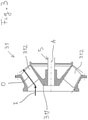
- Fig. 3 shows a cross-sectional view of a mixed flow impeller 31.
- the mixed flow impeller 31 comprises a hub 311 and a plurality of impeller blades 312 arranged on the hub 311.
- the driving fluid flows towards the impeller 31 in an axial direction A, which is defined by the axis of the pump shaft 5.
- the inflow of the driving fluid is indicated by the arrow with the reference numeral I.
- the hub 311 and the impeller blades 312 are configured such that the driving fluid exits the impeller 31 in a direction, which is between the axial direction A and the radial direction.
- the direction, in which the driving fluid exits the impeller 31 is indicated by the arrow with the reference numeral O.
- the angle between the arrow O and the axial direction A is larger than zero and smaller than 90°, e.g. approximately 45°.
- the mixed flow impeller is also suited to handle multiphase process fluids, so that the mixed flow impeller 31 efficiently conveys the driving fluid even if the driving fluid contains a gaseous phase or a solid phase.
- the impeller 31 may also be configured as a radial impeller, which is known in the art.
- a radial impeller may be used for example for a gas content of up to 7%, especially at high pressures.
- the pump system 1 is not restricted to subsea applications, but may be configured for topside locations for example on an offshore oil platform, in particular on an unmanned platform, or on a floating production storage and offloading unit (FPSO) or ashore.
- the rotodynamic pump 10 may be configured as a horizontal pump with the pump shaft 5 extending perpendicular to the direction of gravity.
- the pressure exchanger unit 60 is deployed at a subsea location, for example on the sea ground 100, whereas the rotodynamic pump is deployed at a topside location.
- Fig. 4 shows a cross-sectional view of a configuration of the rotodynamic pump 10 as a horizontal multistage multiphase pump 10 for conveying the driving fluid.
- the multiphase pump 10 is configured with a back-to-back arrangement of the impellers 31.
- the multiphase pump 10 with the back-to-back design is also configured as a helico-axial multistage pump 10 with a plurality of helico-axial impellers 31 (see also Fig. 2 ).
- the rotodynamic pump 10 is configured as a horizontal pump 1, meaning that during operation the pump shaft 5 is extending horizontally, i.e. the axial direction A is perpendicular to the direction of gravity.
- the rotodynamic pump 10 also comprises a drive unit 4, but here the drive unit 4 is not arranged within the pump housing 2 but in a separate motor housing which is not shown in detail.
- the pump shaft 5 extends from a drive end 51 to a non-drive end 52 of the pump shaft 5.
- the pump shaft 5 is configured for rotating about the axial direction A, which is defined by the longitudinal axis of the pump shaft 5.
- All impellers 31 are fixedly mounted on the pump shaft 5 in a torque proof manner.
- the drive unit 4 is configured to exert a torque on the drive end 51 of the pump shaft 5 for driving the rotation of the pump shaft 5 and the impellers 31 about the axial direction A.
- the rotodynamic pump 10 further comprises a plurality of bearings for supporting the pump shaft 5.
- a first radial bearing 53, a second radial bearing 54 and an axial bearing 55 are provided for supporting the pump shaft 5.
- the first radial bearing 53 is arranged adjacent to the drive end 51 of the pump shaft 5.
- the second radial bearing 54 is arranged near the non-drive end 52 of the pump shaft 5.
- the axial bearing 55 is arranged at the non-drive end 52 of the pump shaft 5.
- the bearings 53, 54, 55 are configured to support the pump shaft 5 both in axial and radial direction.
- the radial bearing 53 and 54 are supporting the pump shaft 5 with respect to the radial direction
- the axial bearing 55 is supporting the pump shaft 5 with respect to the axial direction A.
- the bearings 53, 54, 55 are preferably designed as hydrodynamic bearings.
- the first radial bearing 53 at the drive end 51 of the pump shaft 5 is arranged in a first bearing housing 531, which is fixedly mounted to the pump housing 2 and therefore may also be considered as a part of the pump housing 2.
- the second radial bearing 54 at the non-drive end 52 of the pump shaft 5 is arranged in a second bearing housing 541, which is fixedly mounted to the pump housing 2 and therefore may also be considered as a part of the pump housing 2.
- the axial bearing 55 is arranged at the non-drive end 52 of the pump shaft 5 and may be arranged within the second bearing housing 541.
- the multistage, multiphase pump 10 shown in Fig. 4 is configured with eight stages wherein each stage comprises one impeller 31 and one stationary diffusor 32 as it is indicated by the reference numeral K in Fig. 4 .
- the plurality of impellers 31 comprises a first set of impellers 33 and a second set of impellers 34, wherein the first set of impellers 33 and the second set of impellers 34 are arranged in a back-to-back arrangement.
- the first set of impellers 33 comprises the impeller 31 of the first stage, which is the stage next to the driving fluid inlet 11, and the impellers 31 of the stages two, three and four.
- the second set of impellers 34 comprises the impeller 31 of the last stage, which is the stage next to the driving fluid outlet 12, and the impellers 31 of the stages five, six and seven.
- the first set of impellers may comprise a different number of impellers than the second set of impellers.
- the number of eight stages is of course exemplary. In other embodiments there may be more or less than eight stages.
- the first set of impellers 33 and the second set of impellers 34 are arranged such that the axial thrust generated by the action of the rotating first set of impellers 33 is directed in the opposite direction as the axial thrust generated by the action of the rotating second set of impellers 34.
- the driving fluid enters the multistage pump 10 through the driving fluid inlet 11 located at the left side according to the representation in Fig. 4 , passes the stages one (first stage), two, three and four, is then guided through a crossover line 35 to the suction side of the fifth stage impeller, which is the rightmost impeller 31 in Fig. 4 , passes the stages five, six, seven and eight (last stage), and is then discharged through the driving fluid outlet 12.
- the flow of the driving fluid through the first set of impellers 33 is directed essentially in the opposite direction than the flow through the second set of impellers 34.
- the back-to-back arrangement is preferred because the axial thrust acting on the pump shaft 5, which is generated by the first set of impellers 33 counteracts the axial thrust, which is generated by the second set of impellers 34.
- said two axial thrusts compensate each other at least partially.
- a center bush 36 is arranged between the first set of impellers 33 and the second set of impellers 34.
- the center bush 36 is fixedly connected to the pump shaft 5 in a torque proof manner and rotates with the pump shaft 5.
- the center bush 36 is arranged on the pump shaft 5 between the last stage impeller 31, which is the last impeller of the second set of impellers 34, and the impeller 31 of the fourth stage, which is the last impeller 31 of the first set of impellers 33, when viewed in the direction of increasing pressure, respectively.
- the center bush 36 is surrounded by a stationary throttle part being stationary with respect to the pump housing 2.
- An annular balancing passage is formed between the outer surface of the center bush 36 and the stationary throttle part.
- the function of the center bush 36 between the first and the second set of impellers 33, 34 is a balancing of the axial thrust and a damping of the pump shaft 5 based on the Lomakin effect.
- the pressure at the driving fluid outlet 12 prevails, and at the other axial surface facing the impeller 31 of the fourth stage a lower pressure prevails, which is an intermediate pressure between the pressure at the driving fluid outlet 12 and the pressure at the driving fluid inlet 11. Therefore, the process fluid may pass from the impeller 31 of the last stage through the balancing passage along the center bush 36 to the impeller 31 of the fourth stage.
- An axial surface is a surface perpendicular to the axial direction A.
- the pressure drop over the center bush 36 results in a force that is directed to the left according to the representation in Fig. 4 and therewith counteracts the axial thrust generated by the second set of impellers 34, which is directed to the right according to the representation in Fig. 4 .
- the configuration of the rotodynamic pump 10 of the pump system 1 as a multiphase pump 10 is a preferred embodiment but not a requirement.
- the rotodynamic pump 10 may be configured as any other type of rotodynamic pump 10 as explained hereinbefore.
Landscapes
- Engineering & Computer Science (AREA)
- Mechanical Engineering (AREA)
- General Engineering & Computer Science (AREA)
- Structures Of Non-Positive Displacement Pumps (AREA)
Abstract
A pump system is proposed for conveying a multiphase process fluid from a source (20) for the multiphase process fluid to a delivery location (30), the pump system comprising a rotodynamic pump (10) for conveying a driving fluid, and a pressure exchanger unit (60) configured for transferring pressure from the driving fluid to the multiphase process fluid, wherein the rotodynamic pump (10) comprises a driving fluid inlet (11) for receiving the driving fluid, and a driving fluid outlet (12) for discharging the driving fluid, wherein the pressure exchanger unit (60) comprises a low pressure inlet (61), a low pressure discharge (62), a high pressure inlet (64), and a high pressure discharge (63), wherein the low pressure inlet (61) is configured for receiving the multiphase process fluid from the source (20) for the multiphase process fluid, wherein the low pressure discharge (62) is connected to a low pressure line (40), wherein the high pressure inlet (64) is connected to a high pressure line (45), wherein the high pressure discharge (63) is connectable to a delivery line (66) for discharging the multiphase process fluid to the delivery location (30), wherein the low pressure line (40) is connected to the driving fluid inlet (11) of the rotodynamic pump (10), and wherein the high pressure line (45) is connected to the driving fluid outlet (12) of the rotodynamic pump (10).
Description
- The invention relates to a pump system for conveying a multiphase process fluid from a source for the multiphase process fluid to a delivery location, wherein the pump system comprises a rotodynamic pump and a pressure exchanger unit.
- A well-known example of a multiphase process fluid is a combination comprising crude oil, water and hydrocarbon gas. In the oil and gas processing industry, there is a need for conveying or transporting such hydrocarbon containing process fluids, for example for extracting the crude oil from the oil field or for transportation of the oil/gas through pipelines or within refineries. One of the challenges regarding conveying or pumping multiphase process fluids is the fact that in many applications the composition of the multiphase process fluid is strongly varying during operation of the pump(s). For example, during exploitation of an oil field the ratio of the gaseous phase (e.g. natural gas) and the liquid phase (e.g. crude oil) is strongly varying. These variations may occur very suddenly. The ratio of the gaseous phase in the multiphase process fluid is commonly described by the dimensionless gas volume fraction (GVF) designating the volume ratio of the gas in the multiphase process fluid. To pump such multiphase process fluids multiphase pumps are known, which can handle gas volume fraction from 0% to 100%. In many embodiments the multiphase pump comprises a plurality of helico-axial impellers for pumping the process fluid.
- In view of an efficient exploitation of oil and gas fields, there is nowadays an increasing demand for multiphase pumps that may be installed directly on the sea ground in particular down to a depth of 500 m, down to 1000 m or even down to more than 2000 m beneath the water surface. Needless to say that the design of such pumps is challenging, in particular because these pumps shall operate in a difficult subsea environment for a long time period with as little as possible maintenance and service work. This requires specific measures to minimize the amount of equipment involved and to optimize the reliability of the pump.
- Large efforts are made to optimize such pumps for subsea applications regarding robustness, weight, length, efficiency and susceptibility to damage. Furthermore, the complexity of the pump should be minimized without jeopardizing operational safety and reliability.
- Also for topside applications, i.e. on or above the water surface, or for onshore applications it is often necessary to transport the multiphase process fluid over long distances in the piping connecting the multiphase pump at or near the well with the processing facility.
- Rotodynamicmultiphase pumps, which can operate under constantly changing operating conditions and can handle multiphase process fluids with a GVF ranging from 0 to 100%, are typically configured as multistage pumps with a plurality of helico-axial impellers arranged one after another which results in a long rotor of the pump. Typically, the long rotor is supported by hydrodynamic bearings. It is well known that, depending on the gas content in the multiphase process fluid, the (subsea) multiphase pump can exhibit a challenging rotordynamic behavior. This is linked to several factors, including long rotors, complex internal flow regimes due to phase separation and reduced rotordynamic damping, especially at high gas contents. Furthermore, in a vertical configuration, i.e. the pump shaft extends in the vertical direction (direction of gravity), there is no force or nearly no force in the bearing plane of the radial bearings, which pulls the shaft in one specific direction. There is nearly no load generated on the radial bearings by the weight of the pump shaft and the impeller(s) and there is no defined direction of the static load. This means that the pump shaft does not have a preferred position in the bearing clearance of the radial bearing(s). Therefore, a small excitation is enough to make the pump shaft move within the bearing clearance.
- Furthermore, a multiphase pump with helico-axial impellers is limited regarding the pressure increase generated by the pump. Therefore the multiphase pump may not provide very high boosting pressures, in particular if the multiphase process fluid contains a predominant gaseous phase, i.e. the process fluid has a high GVF.
- In particular regarding the rotordynamic behavior, it is a known measure to address such challenges by limiting the number of stages of the pump. However, this measure even further restricts the available boosting pressure. Furthermore, the pump efficiency for multiphase process fluids containing large amounts of gas is quite low.
- The present invention addresses these problems.
- It is therefore an object of the invention to propose a pump system for conveying a multiphase process fluid, wherein the pump system can generate a high pressure difference, in particular also for multiphase process fluids having strongly varying and/or high gas volume fractions. The pump system shall be suited for being configured for subsea applications and for deployment on the sea ground.
- The subject matter of the invention satisfying this object is characterized by the features of the independent claim.
- Thus, according to the invention, a pump system is proposed for conveying a multiphase process fluid from a source for the multiphase process fluid to a delivery location, the pump system comprising a rotodynamic pump for conveying a driving fluid, and a pressure exchanger unit configured for transferring pressure from the driving fluid to the multiphase process fluid, wherein the rotodynamic pump comprises a driving fluid inlet for receiving the driving fluid, and a driving fluid outlet for discharging the driving fluid, wherein the pressure exchanger unit comprises a low pressure inlet, a low pressure discharge, a high pressure inlet, and a high pressure discharge, wherein the low pressure inlet is configured for receiving the multiphase process fluid from the source for the multiphase process fluid, wherein the low pressure discharge is connected to a low pressure line, wherein the high pressure inlet is connected to a high pressure line, wherein the high pressure discharge is connectable to a delivery line for discharging the multiphase process fluid to the delivery location, wherein the low pressure line is connected to the driving fluid inlet of the rotodynamic pump, and wherein the high pressure line is connected to the driving fluid outlet of the rotodynamic pump.
- The pump system according to the invention comprises a rotodynamic pump and a pressure exchanger, wherein the rotodynamic pump pressurizes a driving fluid, and the pressure exchanger is used for transferring the pressure from the driving fluid to the multiphase process fluid. Preferably the driving fluid is a liquid or has a predominant liquid phase. The driving fluid which is supplied to the pressure exchanger is discharged to the low pressure line and recirculated to the driving fluid inlet of the rotodynamic pump. Accordingly, the driving fluid is circulated in a driving loop, in which it is alternately pressurized by the rotodynamic pump and pressure relieved by transferring energy in the form of pressure to the multiphase process fluid.
- The pump system according to the invention may be considered as an indirect pumping system. The multiphase process fluid coming from the source is boosted by means of the energy (pressure) transfer taking place in the pressure exchanger. The driving loop together with the pressure exchanger forms a kind of boosting station. Transferring the pressure from the driving fluid to the multiphase process fluid allows to transport the process fluid over long distances in the piping connecting this boosting station and the processing facility for the process fluid.
- A considerable advantage of the pump system of the invention is the fact that even strong variations in the GVF of the multiphase process fluid or a high GVF of the process fluid do not significantly influence the efficiency of the rotodynamic pump. Of course, a minor mass transfer from the process fluid to the driving fluid may take place in the pressure exchanger, but this does not significantly influence the efficiency of the rotodynamic pump. Strong variations in the GVF predominantly result in modifying the compression the process fluid experiences, but do not or at least not strongly influence the performance of the rotodynamic pump.
- Preferably, the pump system is configured to supply a liquid as driving fluid to the driving fluid inlet of the rotodynamic pump. Thus, even if a mass transfer of gas takes place from the process fluid to the driving fluid, the amount of gas in the driving fluid conveyed by the rotodynamic pump is strongly limited. The rotodynamic pump is expected to convey predominantly a liquid phase with only a small amount of gas (and potentially solids) leaked to the driving loop through the pressure exchanger. In this way the rotodynamic pump can produce a significant pressure increase or boosting pressure regardless of the specific composition of the multiphase mixture process fluid. The high pressure increase generated by the rotodynamic pump is possible because of the high density of the predominantly liquid phase in the driving fluid. In addition, the high pressure increase may be generated with a reduced number of stages as compared to a classical multistage multiphase pump. Furthermore, the high density of the liquid driving fluid provides an increased rotordynamic damping in the rotodynamic pump. The reduced number of stages together with the increased rotordynamic damping considerably increases the reliability of the pump. The high boosting pressure generated by the rotodynamic pump is then transferred to the multiphase process fluid with the help of the pressure exchanger.
- Furthermore, the pump system according to the invention has a high process flexibility, because the pump system may be used for many different applications, for example for many different sources of a multiphase process fluid, without considerable modifications of the pump system.
- In applications in the oil and gas industry the increased boosting pressure allows e.g. for an increased hydrocarbon production, an enhanced economic viability of an oil field. In addition, the increased boosting pressure renders possible the exploitation of oil and gas fields that are unsuited for exploitation with conventional multiphase pump technology.
- According to a preferred design a suction line is connected to the low pressure inlet of the pressure exchanger unit, wherein the suction line is connectable to the source for the multiphase process fluid and configured to supply the multiphase process fluid to the low pressure inlet with a low pressure being essentially the same pressure as the pressure at an exit of the source. Thus, the multiphase process fluid is directly guided from the source, e.g. a well, to the low pressure inlet of the pressure exchanger unit.
- Preferably the pump system is configured for conveying a multiphase process fluid having a gas volume fraction from 0% to 100%.
- In view of applications in the oil and gas processing industry the pump system is preferably configured for conveying a multiphase process fluid comprising at least crude oil and a hydrocarbon gas.
- According to a particularly preferred configuration the rotodynamic pump is configured as a multiphase pump. This has the additional advantage, that a small mass transfer, e.g. of a gaseous phase or a solid phase from the multiphase process fluid to the driving fluid in the pressure exchanger does not jeopardize a safe and efficient operation of the rotodynamic pump.
- For embodiments of the rotodynamic pump as a multiphase pump it is preferred that the rotodynamic pump comprises at least one mixed flow impeller or at least one helico-axial impeller. Of course, the pump may also comprise at least one radial impeller.
- According to a preferred embodiment the pump system comprises a supply line for suppling driving fluid to the rotodynamic pump, wherein the supply line is connected to the low pressure line. By this measure it is possible to add driving fluid to the driving loop, for example to replace driving fluid that has leaked out of the driving loop.
- Even more preferred said embodiment comprises a reservoir for the driving fluid as well as a supply pump for pressurizing the driving fluid to a supply pressure, wherein the supply pump discharges the pressurized driving fluid to the supply line. Thus, it is possible to modify the pressure in the low pressure line and therewith the suction pressure of the rotodynamic pump. If for example, the low pressure of the multiphase process fluid decreases due to changes at the source, the pressure of the driving fluid in the low pressure line may be increased by means of the supply pump so that the pressure at the driving fluid outlet of the rotodynamic pump remains essentially the same as before the decrease in the low pressure at the source.
- According to another example the pressure of the driving fluid in the low pressure line may be reduced, when the low pressure of the multiphase process fluid decreases due to changes at the source. By reducing the pressure of the driving fluid in the low pressure line a kind of suction effect is created, which causes the multiphase process fluid to flow into the low pressure inlet of the pressure exchanger. The pressure of the driving fluid in the low pressure line is preferably adjusted to be somewhat lower than the low pressure at the low pressure inlet of the pressure exchanger. If a higher head is required for the process fluid, this may be achieved for example by increasing the rotational speed the of the rotodynamic pump.
- Therefore, it is also preferred that the pump system comprises a control unit which is configured to modify the supply pressure as a function of the low pressure of the multiphase process fluid prevailing at the low pressure inlet of the pressure exchanger unit. Thus, a required pressure at the high pressure discharge of the pressure exchanger unit may be maintained or controlled even if variations of the low pressure at the low pressure inlet of the pressure exchanger unit occur.
- Regarding the operation it is for example possible that the control unit is configured to adjust the supply pressure to a value, which is at least as large as the difference of a delivery pressure of the multiphase process fluid at the delivery location and the low pressure of the multiphase process fluid at the low pressure inlet of the pressure exchange unit.
- According to a preferred application at least the rotodynamic pump and the pressure exchanger unit are configured for installation on a sea ground or for any other subsea application.
- For a preferred subsea application, the low pressure inlet of the pressure exchanger unit is connectable to a well for exploiting an oil and/or gas field.
- Furthermore, for subsea applications it is preferred that the rotodynamic pump and the pressure exchanger unit are located at the same level beneath the water surface.
- In addition, for subsea applications it is preferred that the supply pump is arranged at a topside location, on or above the water surface. For example, the supply pump may be arranged ashore or on an oil platform, in particular on an unmanned platform, or one a FPSO (Floating Production Storage and Offloading Unit).
- Further advantageous measures and embodiments of the invention will become apparent from the dependent claims.
- The invention will be explained in more detail hereinafter with reference to embodiments of the invention and with reference to the drawings. There are shown in a schematic representation:
- Fig. 1:
- a schematic representation of an embodiment of a pump system according to the invention,
- Fig. 2:
- a perspective view of a helico-axial impeller, and
- Fig. 3:
- a cross-sectional view of a mixed flow impeller, and
- Fig. 4:
- a cross-sectional view of a configuration of a multiphase pump having a back-to back design.
-
Fig. 1 shows a schematic representation of an embodiment of a pump system according to the invention, which is designated in its entity withreference numeral 1. Thepump system 1 is configured for conveying a multiphase process fluid from asource 20 for the multiphase process fluid to adelivery location 30. Thepump system 1 comprises arotodynamic pump 10 for conveying a driving fluid and apressure exchanger unit 60 for transferring pressure from the driving fluid to the multiphase process fluid in order to compress and pressurize the multiphase process fluid. - The
pressure exchanger unit 60 comprises alow pressure inlet 61, alow pressure discharge 62, ahigh pressure inlet 64 and ahigh pressure discharge 63. Therotodynamic pump 10 comprises a drivingfluid inlet 11 for receiving the driving fluid and a drivingfluid outlet 12 for discharging the driving fluid. - The
pump system 1 further comprises alow pressure line 40 connecting thelow pressure discharge 62 of thepressure exchanger unit 60 with the drivingfluid inlet 11 therotodynamic pump 10 for providing a fluid communication between thelow pressure discharge 62 and the drivingfluid inlet 11. - The
pump system 1 further comprises ahigh pressure line 45 connecting the drivingfluid outlet 12 of therotodynamic pump 10 with thehigh pressure inlet 64 of thepressure exchanger unit 60 for providing a fluid communication between the drivingfluid outlet 12 and thehigh pressure inlet 64. - The
low pressure inlet 61 of thepressure exchanger unit 60 is connected to thesource 20 for the multiphase process fluid by asuction line 65 providing a fluid communication between thesource 20 and thelow pressure inlet 61. Preferably, thesuction line 65 directly connects thesource 20 with thelow pressure inlet 61, so that the multiphase process fluid is supplied to thelow pressure inlet 61 with a low pressure being essentially the same pressure as the pressure of the multiphase process fluid at anexit 21 of thesource 20. "Essentially the same" means that there may be a pressure drop over thesuction line 65, so that the pressure of the multiphase process fluid at thelow pressure inlet 61 is somewhat lower than the pressure of the multistage process fluid at theexit 21 of thesource 20. - The
high pressure discharge 63 of thepressure exchanger unit 60 is connected to adelivery line 66 extending to thedelivery location 30 and providing a fluid communication between thehigh pressure discharge 63 and thedelivery location 30. The multiphase process fluid is discharged from thepressure exchanger unit 60 to thedelivery line 66 with a high pressure that is usually considerably larger than the low pressure of the multiphase process fluid at thelow pressure inlet 61. - By means of the
rotodynamic pump 10 the driving fluid is circulated in a driving loop, namely from the drivingfluid outlet 12 through thehigh pressure line 45 to thehigh pressure inlet 64 of thepressure exchanger unit 60 and from thelow pressure discharge 62 of thepressure exchanger unit 60 through thelow pressure line 40 back to the drivingfluid inlet 11 of therotodynamic pump 10. Thus, in the driving loop the driving fluid is alternately pressurized by therotodynamic pump 10 and pressure relieved by transferring energy in the form of pressure to the multiphase process fluid in thepressure exchanger unit 60. The driving loop may be configured as a closed loop. Preferably, the driving loop is configured as a semi-closed loop, meaning that during operation of thepump system 1 additional driving fluid may be added or refilled, for example for replacing leakage losses. - Except for minor pressure losses in the
pressure exchanger unit 60, thelow pressure line 40 and thehigh pressure line 45, the pressure increase, which is generated by therotodynamic pump 10, i.e. the difference of the pressure of the driving fluid at the drivingfluid outlet 12 and the drivingfluid inlet 11, is transferred from the driving fluid to the multiphase process fluid by means of thepressure exchanger unit 60. Accordingly, when disregarding said minor pressure losses, the difference of the high pressure of the multiphase process fluid at thehigh pressure discharge 63 and the low pressure of the multiphase process fluid at thelow pressure inlet 61 equals the pressure increase in the driving fluid generated by therotodynamic pump 10. - Preferably, the driving fluid is a high dense fluid. Within the scope of this application a high dense fluid is a fluid having a specific gravity relative to water, which is at least 0.8, and preferably at least 0.9. As it is commonly used in the art, the specific gravity is the ratio of the density of said fluid to the density of a reference substance. Within the scope of this application the reference fluid is water. Most preferred the driving fluid is a liquid, for example water. Depending on the site of operation of the
pump system 1 the driving fluid may be water or seawater. The term seawater comprises raw seawater, purified seawater, pretreated seawater and filtered seawater. Of course, thepump system 1 according to the invention may also be configured for conveying other driving fluids than water or seawater. - It has to be noted, that during operation of the
pump system 1 the composition of the driving fluid may change, for example due to a mass transfer from the multiphase process fluid to the driving fluid in thepressure exchanger unit 60. It is possible that gas and/or fluid and/or solid particles are transferred from the multiphase process fluid into the driving fluid. - The
pressure exchanger unit 60 comprises one pressure exchanger or a plurality of pressure exchangers. Basically, all pressure exchangers known in the art are suited for thepressure exchanger unit 60. - Independent from the specific configuration of a pressure exchanger the working principle is always the same, namely to transfer pressure from a high pressure fluid, referred to as the driving fluid, to a low pressure fluid, referred to as the pumped fluid, usually by a isobaric process with direct contact of the two fluids in at least one exchange chamber. The exchange chamber is first filled with the pumped fluid. Upon filling the exchange chamber the pumped fluid displaces the driving fluid from the exchange chamber. Once the exchange chamber is filled with the pumped fluid the pressurized driving fluid is supplied to the exchange chamber and displaces the pumped fluid from the exchange chamber, thereby transferring pressure to the pumped fluid.
- There are different embodiments known in the art for pressure exchangers. In one embodiment the exchange chamber is configured as a cylindrical tube having a valve system at each end thereof, for controlling the filling and the discharge of the cylindrical tube. It is also known to arrange and to connect a plurality of such exchange chambers in parallel.
- Furthermore, pressure exchangers are known having a rotor configured for rotation about a longitudinal axis. The rotor comprises a plurality of channels extending longitudinally through the rotor. Such a pressure exchanger is for example disclosed in
US 9,970,281 - The
rotodynamic pump 10 of thepump system 1 may be configured as any rotodynamic pump known in the art. Rotodynamic pumps 10 are also referred to as hydrodynamic pumps. Arotodynamic pump 10 may be configured as a centrifugal pump. A centrifugal pump has at least one rotating impeller for transferring energy to the fluid to be conveyed by the pump. The at least one impeller may be configured as a radial impeller, as an axial impeller or as a mixed flow impeller. Therotodynamic pump 10 may also be configured with at least one helico-axial impeller. - Rotodynamic pumps are known in a great variety of embodiments such as single stage pumps, multistage pumps, single phase pumps or multiphase pumps, just to list a few examples. A multistage pump comprises a plurality of impellers, which are arranged on a common shaft. Multiphase pumps may handle multiphase fluids, for example a mixture of a liquid phase and/or a gas phase and/or a solid phase, and/or a dense phase. The dense phase is sometimes also referred to as supercritical phase. An example for a multiphase fluid is a hydrocarbon fluid which is for example extracted from an oil or gas field. Modern multiphase pumps can handle multiphase process fluids having a gas volume fraction from 0% to 100%.
- Furthermore, the
rotodynamic pump 10 may be configured as a process fluid lubricated pump. The term "process fluid lubricated pump" refers to a rotodynamic pump, wherein the process fluid that is conveyed by the pump is used for the lubrication and the cooling of components of the pump, e.g. bearing units. - The
rotodynamic pump 10 may be designed as a seal-less pump without a mechanical seal. A mechanical seal is usually used for the sealing of the rotating shaft of arotodynamic pump 10 and shall prevent the leakage of the process fluid along the shaft of the pump. Typically, a mechanical seal comprises a stator and a rotor. The rotor is connected in a torque-proof manner with the shaft of the pump and the stator is fixed with respect to the pump housing such that the stator is secured against rotation. During rotation of the shaft the rotor is in sliding contact with the stator thus performing the sealing action. Although such mechanical seals are widely spread within the technology of rotodynamic pumps they are somewhat problematic in particular for subsea applications because they are quite complicated and usually require additional equipment, which is often considered as a drawback for subsea applications. Therefore, it is advantageous that therotodynamic pump 10 may also be designed as a seal-less pump, i.e. a pump that has no mechanical seal. In many applications, in particular where therotodynamic pump 10 comprises a pump unit and a drive unit arranged in a common housing, the seal-less design requires that the pump unit and the drive unit are flooded with the process fluid. The advantage of the seal-less pump is the simpler design of the pump. In addition, the process fluid itself may be used for cooling and lubricating components of the pump, e.g. the bearing units of the pump shaft and the drive unit of the pump. - The
rotodynamic pump 10 may be configured as a vertical pump with the pump shaft extending in the direction of gravity. When therotodynamic pump 10 also comprise a drive unit for rotating the pump shaft, said drive unit is preferably arranged on top of the pump unit. - The
rotodynamic pump 10 may also be configured as a horizontal pump with the pump shaft extending perpendicular to the direction of gravity. Such embodiments of thepump system 1 with therotodynamic pump 10 configured as a horizontal pump may be used for example at topside locations on an offshore platform or on a floating production storage and offloading unit (FPSO) or ashore, e.g. for transporting a hydrocarbon fluid from a well through a piping to a processing facility. - According to the preferred embodiment of the pump system illustrated in
Fig. 1 , thepump system 1 further comprises asupply line 13 for supplying driving fluid to therotodynamic pump 10. Thesupply line 13 is connected to thelow pressure line 40 at any location between thelow pressure discharge 62 of thepressure exchanger unit 60 and the drivingfluid inlet 11 of therotodynamic pump 10. The driving fluid is fed to thesupply line 13 from areservoir 14, which may be for example atank 14 or anatural reservoir 14 such as the sea, a lake or a river. By supplying additional driving fluid to thelow pressure line 40 it is possible to compensate leakage losses in the driving loop. - Preferably, the
pump system 1 further comprises asupply pump 15 for pressurizing the driving fluid, which is fed to thesupply line 13, to a supply pressure. Thereservoir 14 is in fluid communication with an inlet of thesupply pump 15. Thesupply pump 15 pressurizes the driving fluid to the supply pressure and discharges the pressurized driving fluid into thesupply line 13. From thesupply line 13 the driving fluid is inserted into thelow pressure line 40. This configuration has the advantage that by means of thesupply pump 15 and thesupply line 13 the pressure in thelow pressure line 40 may be modified, in particular the pressure in thelow pressure line 40 may be increased to the supply pressure. Thus, the suction pressure at the drivingfluid inlet 11 of therotodynamic pump 10 may be increased to a desired value given by the supply pressure generated by thesupply pump 15. Increasing the suction pressure at the drivingfluid inlet 11 of therotodynamic pump 10, also increases the pressure at the drivingfluid outlet 12 of the rotodynamic pump. This leads to an increase of the high pressure, with which the multiphase process fluid is discharged from thepressure exchanger unit 60 to thedelivery line 66. Thus, by varying the supply pressure generated by means of thesupply pump 15 the high pressure at thehigh pressure discharge 63 of thepressure exchanger unit 60 may be modified or controlled. - Of course, it is also possible to operate the
pump system 1 such that the pressure in thesupply line 13 follows the pressure or the pressure changes, respectively, at theexit 21 of thesource 20. It is true that a higher suction pressure at the drivingfluid inlet 11 of therotodynamic pump 10 translates into a higher pressure at the drivingfluid outlet 12 of the rotodynamic pump and therewith leads to an increase of the high pressure, with which the multiphase process fluid is discharged from thepressure exchanger unit 60 to thedelivery line 66, but the pressure at the drivingfluid outlet 12 of therotodynamic pump 10 may also be adjusted by a regulation of the rotational speed of therotodynamic pump 10. - In conventional subsea systems, the discharge pressure of the pump is for example fixed by the downstream piping which has large "inertia" imposed by the liquid column (approximately 1000 m or even more) and the receiving facility. Therefore, if in such a system the head of the pump is increased, for example by increasing the rotational speed of the pump, mainly the suction pressure is affected, namely lowered.
- In the
pump system 1 configured in accordance with the invention therotodynamic pump 10 is not directly linked or connected to thesource 20. Therefore it might be advantageous to act on the low pressure in thelow pressure line 40 in such a manner that a suction effect is created at theexit 21 of thesource 20. By this it is possible to increase for example the production of hydrocarbons. - Preferably the
pump system 1 further comprises acontrol unit 16, which is configured to modify the supply pressure (and in turn pump speed) as a function of the low pressure of the multiphase process fluid prevailing at thelow pressure inlet 61 of the pressure exchanger unit 60 (correct). Furthermore, thecontrol unit 16 may be configured to control the rotational speed of therotodynamic pump 10 and/or thesupply pump 15. By adjusting the rotational speed of therotodynamic pump 10, the pressure of the driving fluid at the drivingfluid outlet 12 may be controlled. - The preferred embodiment of the
pump system 1 represented inFig. 1 is for example configured for a subsea application in the oil and gas industry, more particular for exploiting an oil and gas field at a subsea location, which will now be explained in more detail. Thepump system 1 is used for extracting a crude oil containing hydrocarbon fluid from the oil field and conveying the hydrocarbon fluid to a top side location. - In this example the multiphase process fluid is a hydrocarbon fluid containing at least crude oil and a hydrocarbon gas, such as natural gas, carbon dioxide (CO2) or methane. The
source 20 for the multiphase process fluid is a well 20 having theexit 21 located on asea ground 100. Therotodynamic pump 10 and thepressure exchanger unit 60 are configured for an installation on thesea ground 100 at a level having a vertical distance D from thewater surface 200. Therotodynamic pump 10 and thepressure exchanger unit 60 are located at the same level beneath thewater surface 200. The distance D may be for example 500 m, up to 1000 m or even more than 2000 m. The required pressure measured in bar for transporting the multiphase process fluid from the sea ground 100 to thewater surface 200 is approximately a tenth of the value of D. Thus, if D equals for example 1500m, the required pressure for transporting the multiphase process fluid from the sea ground 100 to thewater surface 200 is 150 bar (15 MPa). - The
delivery location 30 is a topside location located on or above thewater surface 200, for example a platform or on an FPSO (floating production storage and offloading) unit. Thesupply pump 15 and optionally thecontrol unit 16 are arranged at thedelivery location 30. As an alternative also therotary pump 10 may be located at or near the delivery location. Thereservoir 14 for the driving fluid may be arranged at thedelivery location 30. Alternatively, the sea constitutes thereservoir 14. The driving fluid is preferably water or seawater. - The
low pressure inlet 61 of thepressure exchanger unit 60 is connected to and in fluid communication with theexit 21 of the well forming thesource 20 for the multiphase process fluid by means of thesuction line 65. Thehigh pressure discharge 63 of thepressure exchanger unit 60 is in fluid communication with thedelivery location 30 by means of thedelivery line 66. - In the described embodiment the
rotodynamic pump 10 is configured as a multistage, multiphase subsea pump. Configuring therotodynamic pump 10 as a multiphase pump has the advantage that therotodynamic pump 10 may pressurize the driving fluid and circulate the driving fluid through the driving loop with a high efficiency even if the liquid driving fluid contains a gaseous phase or a solid phase, which might be introduced into the driving fluid in thepressure exchanger unit 60 by a mass transfer between the multiphase process fluid and the driving fluid. - Multistage, multiphase rotodynamic pumps 10 configured as subsea pumps for deployment on the
sea ground 100 are known in the art. Therefore saidrotodynamic pump 10 is only briefly described. - The multistage
multiphase pump 10 configured for installation on thesea ground 100, has a common pump housing 2 (seeFig. 2 ), a pump unit arranged in thecommon pump housing 2, and a drive unit arranged in thecommon pump housing 2, wherein thecommon pump housing 2 comprises the drivingfluid inlet 11 and the drivingfluid outlet 12. The pump unit comprises a plurality ofimpellers 31 for conveying the driving fluid from the drivingfluid inlet 11 to the drivingfluid outlet 12. Thepump 10 further comprises apump shaft 5, on which eachimpeller 31 is mounted. The drive unit comprises a drive shaft for driving thepump shaft 5, and an electric motor for rotating the drive shaft about an axial direction, wherein a coupling is provided for coupling the drive shaft to thepump shaft 5. Preferably, therotodynamic pump 10 is configured as a vertical pump with the pump shaft (5) extending in the direction of gravity. The drive unit of therotodynamic pump 10 is preferably arranged on top of the pump unit. - Furthermore, the plurality of
impellers 31 are preferably arranged in a back-to-back arrangement. In other embodiments allimpellers 31 are arranged in an inline arrangement. - The
rotodynamic pump 10 of thepump system 1 comprises at least onemixed flow impeller 31 or at least one helico-axial impeller 31 or at least oneradial impeller 31. - According to a preferred design the
rotodynamic pump 10 is configured as a helico-axial pump, wherein eachimpeller 31 is configured as a helico-axial impeller 31. Helico-axial impellers 31 and helico-axialmultiphase pumps 1 as such are known in the art.Fig. 2 shows a perspective view of two helico-axial impellers 31 with astationary diffusor 32 interposed between these twoimpellers 31. InFig. 2 half of thecommon housing 2 has been removed to render visible the helico-axial impellers 31. A helico-axial impeller 31 has at least oneblade 38 that extends helically around the hub of theimpeller 31 or thepump shaft 5, respectively. In many embodiments each helico-axial impeller 31 comprises a plurality ofblades 38, for example fiveblades 38, each of which extends helically around thepump shaft 5 or the hub of theimpeller 31, respectively. Eachblade 38 has a radiallyouter tip 381. Optionally eachimpeller 31 may comprise a ring (not shown) arranged at the radiallyouter tips 381 of theblades 38, so that the ring forms the radially outer surface of theimpeller 31. The ring is fixed with respect to theouter tips 381, so that the ring is connected to theimpeller 31 in a torque proof manner. The design of theimpeller 31 with the ring disposed along the radiallyouter tips 381 of theblades 38 is also referred to as a "shrouded impeller" 31. The ring may cover theimpeller 31 over its entire axial length, but it is also possible that the axial length of the ring is smaller than the axial length of theimpeller 31. - According to another preferred design each
impeller 31 is designed as amixed flow impeller 31. Amixed flow impeller 31 is also referred to as a semi-axial impeller.Fig. 3 shows a cross-sectional view of amixed flow impeller 31. Themixed flow impeller 31 comprises ahub 311 and a plurality ofimpeller blades 312 arranged on thehub 311. The driving fluid flows towards theimpeller 31 in an axial direction A, which is defined by the axis of thepump shaft 5. The inflow of the driving fluid is indicated by the arrow with the reference numeral I. Thehub 311 and theimpeller blades 312 are configured such that the driving fluid exits theimpeller 31 in a direction, which is between the axial direction A and the radial direction. The direction, in which the driving fluid exits theimpeller 31 is indicated by the arrow with the reference numeral O. As can be seen the angle between the arrow O and the axial direction A is larger than zero and smaller than 90°, e.g. approximately 45°. The mixed flow impeller is also suited to handle multiphase process fluids, so that themixed flow impeller 31 efficiently conveys the driving fluid even if the driving fluid contains a gaseous phase or a solid phase. In particular depending on the content of gas in the driving fluid, theimpeller 31 may also be configured as a radial impeller, which is known in the art. A radial impeller may be used for example for a gas content of up to 7%, especially at high pressures. - As already mentioned the
pump system 1 according to the invention is not restricted to subsea applications, but may be configured for topside locations for example on an offshore oil platform, in particular on an unmanned platform, or on a floating production storage and offloading unit (FPSO) or ashore. In particular for such applications therotodynamic pump 10 may be configured as a horizontal pump with thepump shaft 5 extending perpendicular to the direction of gravity. - Furthermore it is also possible that the
pressure exchanger unit 60 is deployed at a subsea location, for example on thesea ground 100, whereas the rotodynamic pump is deployed at a topside location. -
Fig. 4 shows a cross-sectional view of a configuration of therotodynamic pump 10 as a horizontal multistagemultiphase pump 10 for conveying the driving fluid. Themultiphase pump 10 is configured with a back-to-back arrangement of theimpellers 31. - The
multiphase pump 10 with the back-to-back design is also configured as a helico-axialmultistage pump 10 with a plurality of helico-axial impellers 31 (see alsoFig. 2 ). Furthermore, therotodynamic pump 10 is configured as ahorizontal pump 1, meaning that during operation thepump shaft 5 is extending horizontally, i.e. the axial direction A is perpendicular to the direction of gravity. Therotodynamic pump 10 also comprises a drive unit 4, but here the drive unit 4 is not arranged within thepump housing 2 but in a separate motor housing which is not shown in detail. - The
pump shaft 5 extends from adrive end 51 to anon-drive end 52 of thepump shaft 5. Thepump shaft 5 is configured for rotating about the axial direction A, which is defined by the longitudinal axis of thepump shaft 5. - All
impellers 31 are fixedly mounted on thepump shaft 5 in a torque proof manner. The drive unit 4 is configured to exert a torque on thedrive end 51 of thepump shaft 5 for driving the rotation of thepump shaft 5 and theimpellers 31 about the axial direction A. - The
rotodynamic pump 10 further comprises a plurality of bearings for supporting thepump shaft 5. A firstradial bearing 53, a secondradial bearing 54 and anaxial bearing 55 are provided for supporting thepump shaft 5. The firstradial bearing 53 is arranged adjacent to thedrive end 51 of thepump shaft 5. The secondradial bearing 54 is arranged near thenon-drive end 52 of thepump shaft 5. Theaxial bearing 55 is arranged at thenon-drive end 52 of thepump shaft 5. Thebearings pump shaft 5 both in axial and radial direction. Theradial bearing pump shaft 5 with respect to the radial direction, and theaxial bearing 55 is supporting thepump shaft 5 with respect to the axial direction A. Thebearings - The first
radial bearing 53 at thedrive end 51 of thepump shaft 5 is arranged in afirst bearing housing 531, which is fixedly mounted to thepump housing 2 and therefore may also be considered as a part of thepump housing 2. The secondradial bearing 54 at thenon-drive end 52 of thepump shaft 5 is arranged in asecond bearing housing 541, which is fixedly mounted to thepump housing 2 and therefore may also be considered as a part of thepump housing 2. Theaxial bearing 55 is arranged at thenon-drive end 52 of thepump shaft 5 and may be arranged within thesecond bearing housing 541. - The multistage,
multiphase pump 10 shown inFig. 4 is configured with eight stages wherein each stage comprises oneimpeller 31 and onestationary diffusor 32 as it is indicated by the reference numeral K inFig. 4 . - As can be seen in
Fig. 4 the plurality ofimpellers 31 comprises a first set ofimpellers 33 and a second set ofimpellers 34, wherein the first set ofimpellers 33 and the second set ofimpellers 34 are arranged in a back-to-back arrangement. The first set ofimpellers 33 comprises theimpeller 31 of the first stage, which is the stage next to the drivingfluid inlet 11, and theimpellers 31 of the stages two, three and four. The second set ofimpellers 34 comprises theimpeller 31 of the last stage, which is the stage next to the drivingfluid outlet 12, and theimpellers 31 of the stages five, six and seven. - In other embodiments the first set of impellers may comprise a different number of impellers than the second set of impellers. The number of eight stages is of course exemplary. In other embodiments there may be more or less than eight stages.
- In a back-to-back arrangement the first set of
impellers 33 and the second set ofimpellers 34 are arranged such that the axial thrust generated by the action of the rotating first set ofimpellers 33 is directed in the opposite direction as the axial thrust generated by the action of the rotating second set ofimpellers 34. The driving fluid enters themultistage pump 10 through the drivingfluid inlet 11 located at the left side according to the representation inFig. 4 , passes the stages one (first stage), two, three and four, is then guided through acrossover line 35 to the suction side of the fifth stage impeller, which is therightmost impeller 31 inFig. 4 , passes the stages five, six, seven and eight (last stage), and is then discharged through the drivingfluid outlet 12. Thus, the flow of the driving fluid through the first set ofimpellers 33 is directed essentially in the opposite direction than the flow through the second set ofimpellers 34. - For many applications the back-to-back arrangement is preferred because the axial thrust acting on the
pump shaft 5, which is generated by the first set ofimpellers 33 counteracts the axial thrust, which is generated by the second set ofimpellers 34. Thus, said two axial thrusts compensate each other at least partially. - As a further balancing device for reducing the overall axial thrust acting on the
pump shaft 5, acenter bush 36 is arranged between the first set ofimpellers 33 and the second set ofimpellers 34. Thecenter bush 36 is fixedly connected to thepump shaft 5 in a torque proof manner and rotates with thepump shaft 5. Thecenter bush 36 is arranged on thepump shaft 5 between thelast stage impeller 31, which is the last impeller of the second set ofimpellers 34, and theimpeller 31 of the fourth stage, which is thelast impeller 31 of the first set ofimpellers 33, when viewed in the direction of increasing pressure, respectively. Thecenter bush 36 is surrounded by a stationary throttle part being stationary with respect to thepump housing 2. An annular balancing passage is formed between the outer surface of thecenter bush 36 and the stationary throttle part. - The function of the
center bush 36 between the first and the second set ofimpellers pump shaft 5 based on the Lomakin effect. At the axial surface of thecenter bush 35 facing theimpeller 31 of the last stage the pressure at the drivingfluid outlet 12 prevails, and at the other axial surface facing theimpeller 31 of the fourth stage a lower pressure prevails, which is an intermediate pressure between the pressure at the drivingfluid outlet 12 and the pressure at the drivingfluid inlet 11. Therefore, the process fluid may pass from theimpeller 31 of the last stage through the balancing passage along thecenter bush 36 to theimpeller 31 of the fourth stage. An axial surface is a surface perpendicular to the axial direction A. - The pressure drop over the
center bush 36 results in a force that is directed to the left according to the representation inFig. 4 and therewith counteracts the axial thrust generated by the second set ofimpellers 34, which is directed to the right according to the representation inFig. 4 . - It has to be noted that the configuration of the
rotodynamic pump 10 of thepump system 1 as amultiphase pump 10 is a preferred embodiment but not a requirement. In other embodiments therotodynamic pump 10 may be configured as any other type ofrotodynamic pump 10 as explained hereinbefore.
Claims (14)
- A pump system for conveying a multiphase process fluid from a source (20) for the multiphase process fluid to a delivery location (30), the pump system comprising a rotodynamic pump (10) for conveying a driving fluid, and a pressure exchanger unit (60) configured for transferring pressure from the driving fluid to the multiphase process fluid, wherein the rotodynamic pump (10) comprises a driving fluid inlet (11) for receiving the driving fluid, and a driving fluid outlet (12) for discharging the driving fluid, wherein the pressure exchanger unit (60) comprises a low pressure inlet (61), a low pressure discharge (62), a high pressure inlet (64), and a high pressure discharge (63), wherein the low pressure inlet (61) is configured for receiving the multiphase process fluid from the source (20) for the multiphase process fluid, wherein the low pressure discharge (62) is connected to a low pressure line (40), wherein the high pressure inlet (64) is connected to a high pressure line (45), wherein the high pressure discharge (63) is connectable to a delivery line (66) for discharging the multiphase process fluid to the delivery location (30), wherein the low pressure line (40) is connected to the driving fluid inlet (11) of the rotodynamic pump (10), and wherein the high pressure line (45) is connected to the driving fluid outlet (12) of the rotodynamic pump (10).
- A pump system in accordance with claim 1, which is configured to supply a liquid as driving fluid to the driving fluid inlet (11) of the rotodynamic pump (10).
- A pump system in accordance with anyone of the preceding claims, comprising a suction line (65) connected to the low pressure inlet (61) of the pressure exchanger unit (60), wherein the suction line (65) is connectable to the source (20) for the multiphase process fluid and configured to supply the multiphase process fluid to the low pressure inlet (61) with a low pressure being essentially the same pressure as the pressure at an exit (21) of the source (20).
- A pump system in accordance with anyone of the preceding claims, which is configured for conveying a multiphase process fluid having a gas volume fraction from 0% to 100%.
- A pump system in accordance with anyone of the preceding claims, which is configured for conveying a multiphase process fluid comprising at least crude oil and a hydrocarbon gas.
- A pump system in accordance with anyone of the preceding claims, wherein the rotodynamic pump (10) is configured as a multiphase pump.
- A pump system in accordance with anyone of the preceding claims, wherein the rotodynamic pump comprises at least one radial impeller or at least one mixed flow impeller (31) or at least one helico-axial impeller (31).
- A pump system in accordance with anyone of the preceding claims, comprising a supply line (13) for suppling driving fluid to the rotodynamic pump (10), wherein the supply line (13) is connected to the low pressure line (40).
- A pump system in accordance with claim 8, comprising a reservoir (14) for the driving fluid as well as a supply pump (15) for pressurizing the driving fluid to a supply pressure, wherein the supply pump (15) discharges the pressurized driving fluid to the supply line (13).
- A pump system in accordance with claim 9, comprising a control unit (16) which is configured to modify the supply pressure as a function of the low pressure of the multiphase process fluid prevailing at the low pressure inlet (61) of the pressure exchanger unit (60).
- A pump system in accordance with anyone of the preceding claims, wherein at least the rotodynamic pump (10) and the pressure exchanger unit (60) are configured for installation on a sea ground (100).
- A pump system in accordance with claim 11, wherein the low pressure inlet (61) of the pressure exchanger unit (60) is connectable to a well (20) for exploiting an oil and/or gas field.
- A pump system in accordance with anyone of claims 12 - 13, wherein the rotodynamic pump (10) and the pressure exchanger unit (60) are located at the same level beneath the water surface (200).
- A pump system in accordance with anyone of claims 12 - 14, wherein the supply pump (15) is arranged at a topside location, on or above the water surface (200).
Priority Applications (1)
| Application Number | Priority Date | Filing Date | Title |
|---|---|---|---|
| EP20194256.2A EP3964717A1 (en) | 2020-09-03 | 2020-09-03 | Multiphase subsea pressure exchanger |
Applications Claiming Priority (1)
| Application Number | Priority Date | Filing Date | Title |
|---|---|---|---|
| EP20194256.2A EP3964717A1 (en) | 2020-09-03 | 2020-09-03 | Multiphase subsea pressure exchanger |
Publications (1)
| Publication Number | Publication Date |
|---|---|
| EP3964717A1 true EP3964717A1 (en) | 2022-03-09 |
Family
ID=72355837
Family Applications (1)
| Application Number | Title | Priority Date | Filing Date |
|---|---|---|---|
| EP20194256.2A Withdrawn EP3964717A1 (en) | 2020-09-03 | 2020-09-03 | Multiphase subsea pressure exchanger |
Country Status (1)
| Country | Link |
|---|---|
| EP (1) | EP3964717A1 (en) |
Citations (3)
| Publication number | Priority date | Publication date | Assignee | Title |
|---|---|---|---|---|
| US20060204375A1 (en) * | 2005-03-10 | 2006-09-14 | Judge Robert A | Pressure driven pumping system |
| US20150226208A1 (en) * | 2012-10-11 | 2015-08-13 | Fmc Technologies, Inc. | System for operating a hydraulically-powered submersible pump |
| US9970281B2 (en) | 2015-03-23 | 2018-05-15 | Energy Recovery, Inc. | System and method for offshore (topside or subsea) and onshore water reinjection for secondary recovery |
-
2020
- 2020-09-03 EP EP20194256.2A patent/EP3964717A1/en not_active Withdrawn
Patent Citations (3)
| Publication number | Priority date | Publication date | Assignee | Title |
|---|---|---|---|---|
| US20060204375A1 (en) * | 2005-03-10 | 2006-09-14 | Judge Robert A | Pressure driven pumping system |
| US20150226208A1 (en) * | 2012-10-11 | 2015-08-13 | Fmc Technologies, Inc. | System for operating a hydraulically-powered submersible pump |
| US9970281B2 (en) | 2015-03-23 | 2018-05-15 | Energy Recovery, Inc. | System and method for offshore (topside or subsea) and onshore water reinjection for secondary recovery |
Similar Documents
| Publication | Publication Date | Title |
|---|---|---|
| US6457950B1 (en) | Sealless multiphase screw-pump-and-motor package | |
| EP3913227B1 (en) | Multiphase pump | |
| US8393876B2 (en) | Gas tolerant subsea pump | |
| EP3686436A1 (en) | Multistage pump and subsea pumping arrangement | |
| US11415169B2 (en) | Multiphase pump | |
| US12006946B2 (en) | Process fluid lubricated pump and pumping system | |
| EP3726077A1 (en) | Vertical pump and method for retrofitting a vertical pump | |
| EP4257826B1 (en) | Pumping arrangement | |
| CN110905863A (en) | Multiphase pump | |
| US12006949B2 (en) | Multiphase pump | |
| US12163525B2 (en) | Subsea pump system with process lubricated bearings | |
| EP4001658B1 (en) | Rotary pump for conveying a fluid | |
| EP0223335A2 (en) | Improvements in or relating to rotary positive displacement fluid machines | |
| US11788533B2 (en) | Multistage centrifugal pump | |
| EP4474652A1 (en) | Submersible pump | |
| CN119686992A (en) | A counter-rotating mixed flow pump | |
| WO2022199997A1 (en) | Vertical pump | |
| BR102019024355B1 (en) | MULTIPHASE PUMP | |
| BR102020015017B1 (en) | Multistage pump and subsea pumping arrangement |
Legal Events
| Date | Code | Title | Description |
|---|---|---|---|
| PUAI | Public reference made under article 153(3) epc to a published international application that has entered the european phase |
Free format text: ORIGINAL CODE: 0009012 |
|
| STAA | Information on the status of an ep patent application or granted ep patent |
Free format text: STATUS: THE APPLICATION HAS BEEN PUBLISHED |
|
| AK | Designated contracting states |
Kind code of ref document: A1 Designated state(s): AL AT BE BG CH CY CZ DE DK EE ES FI FR GB GR HR HU IE IS IT LI LT LU LV MC MK MT NL NO PL PT RO RS SE SI SK SM TR |
|
| STAA | Information on the status of an ep patent application or granted ep patent |
Free format text: STATUS: THE APPLICATION IS DEEMED TO BE WITHDRAWN |
|
| 18D | Application deemed to be withdrawn |
Effective date: 20220910 |