EP3964712B1 - Compressor and refrigerating device - Google Patents
Compressor and refrigerating device Download PDFInfo
- Publication number
- EP3964712B1 EP3964712B1 EP20937175.6A EP20937175A EP3964712B1 EP 3964712 B1 EP3964712 B1 EP 3964712B1 EP 20937175 A EP20937175 A EP 20937175A EP 3964712 B1 EP3964712 B1 EP 3964712B1
- Authority
- EP
- European Patent Office
- Prior art keywords
- oil
- cavity
- shell
- compressor
- motor
- Prior art date
- Legal status (The legal status is an assumption and is not a legal conclusion. Google has not performed a legal analysis and makes no representation as to the accuracy of the status listed.)
- Active
Links
Images



Classifications
-
- F—MECHANICAL ENGINEERING; LIGHTING; HEATING; WEAPONS; BLASTING
- F04—POSITIVE - DISPLACEMENT MACHINES FOR LIQUIDS; PUMPS FOR LIQUIDS OR ELASTIC FLUIDS
- F04C—ROTARY-PISTON, OR OSCILLATING-PISTON, POSITIVE-DISPLACEMENT MACHINES FOR LIQUIDS; ROTARY-PISTON, OR OSCILLATING-PISTON, POSITIVE-DISPLACEMENT PUMPS
- F04C29/00—Component parts, details or accessories of pumps or pumping installations, not provided for in groups F04C18/00 - F04C28/00
- F04C29/02—Lubrication; Lubricant separation
- F04C29/028—Means for improving or restricting lubricant flow
-
- F—MECHANICAL ENGINEERING; LIGHTING; HEATING; WEAPONS; BLASTING
- F04—POSITIVE - DISPLACEMENT MACHINES FOR LIQUIDS; PUMPS FOR LIQUIDS OR ELASTIC FLUIDS
- F04B—POSITIVE-DISPLACEMENT MACHINES FOR LIQUIDS; PUMPS
- F04B39/00—Component parts, details, or accessories, of pumps or pumping systems specially adapted for elastic fluids, not otherwise provided for in, or of interest apart from, groups F04B25/00 - F04B37/00
- F04B39/02—Lubrication
- F04B39/0223—Lubrication characterised by the compressor type
- F04B39/023—Hermetic compressors
-
- F—MECHANICAL ENGINEERING; LIGHTING; HEATING; WEAPONS; BLASTING
- F04—POSITIVE - DISPLACEMENT MACHINES FOR LIQUIDS; PUMPS FOR LIQUIDS OR ELASTIC FLUIDS
- F04B—POSITIVE-DISPLACEMENT MACHINES FOR LIQUIDS; PUMPS
- F04B39/00—Component parts, details, or accessories, of pumps or pumping systems specially adapted for elastic fluids, not otherwise provided for in, or of interest apart from, groups F04B25/00 - F04B37/00
- F04B39/02—Lubrication
- F04B39/0284—Constructional details, e.g. reservoirs in the casing
-
- F—MECHANICAL ENGINEERING; LIGHTING; HEATING; WEAPONS; BLASTING
- F04—POSITIVE - DISPLACEMENT MACHINES FOR LIQUIDS; PUMPS FOR LIQUIDS OR ELASTIC FLUIDS
- F04C—ROTARY-PISTON, OR OSCILLATING-PISTON, POSITIVE-DISPLACEMENT MACHINES FOR LIQUIDS; ROTARY-PISTON, OR OSCILLATING-PISTON, POSITIVE-DISPLACEMENT PUMPS
- F04C23/00—Combinations of two or more pumps, each being of rotary-piston or oscillating-piston type, specially adapted for elastic fluids; Pumping installations specially adapted for elastic fluids; Multi-stage pumps specially adapted for elastic fluids
- F04C23/008—Hermetic pumps
-
- F—MECHANICAL ENGINEERING; LIGHTING; HEATING; WEAPONS; BLASTING
- F04—POSITIVE - DISPLACEMENT MACHINES FOR LIQUIDS; PUMPS FOR LIQUIDS OR ELASTIC FLUIDS
- F04C—ROTARY-PISTON, OR OSCILLATING-PISTON, POSITIVE-DISPLACEMENT MACHINES FOR LIQUIDS; ROTARY-PISTON, OR OSCILLATING-PISTON, POSITIVE-DISPLACEMENT PUMPS
- F04C29/00—Component parts, details or accessories of pumps or pumping installations, not provided for in groups F04C18/00 - F04C28/00
-
- F—MECHANICAL ENGINEERING; LIGHTING; HEATING; WEAPONS; BLASTING
- F04—POSITIVE - DISPLACEMENT MACHINES FOR LIQUIDS; PUMPS FOR LIQUIDS OR ELASTIC FLUIDS
- F04C—ROTARY-PISTON, OR OSCILLATING-PISTON, POSITIVE-DISPLACEMENT MACHINES FOR LIQUIDS; ROTARY-PISTON, OR OSCILLATING-PISTON, POSITIVE-DISPLACEMENT PUMPS
- F04C29/00—Component parts, details or accessories of pumps or pumping installations, not provided for in groups F04C18/00 - F04C28/00
- F04C29/0042—Driving elements, brakes, couplings, transmissions specially adapted for pumps
- F04C29/005—Means for transmitting movement from the prime mover to driven parts of the pump, e.g. clutches, couplings, transmissions
-
- F—MECHANICAL ENGINEERING; LIGHTING; HEATING; WEAPONS; BLASTING
- F04—POSITIVE - DISPLACEMENT MACHINES FOR LIQUIDS; PUMPS FOR LIQUIDS OR ELASTIC FLUIDS
- F04C—ROTARY-PISTON, OR OSCILLATING-PISTON, POSITIVE-DISPLACEMENT MACHINES FOR LIQUIDS; ROTARY-PISTON, OR OSCILLATING-PISTON, POSITIVE-DISPLACEMENT PUMPS
- F04C29/00—Component parts, details or accessories of pumps or pumping installations, not provided for in groups F04C18/00 - F04C28/00
- F04C29/02—Lubrication; Lubricant separation
-
- F—MECHANICAL ENGINEERING; LIGHTING; HEATING; WEAPONS; BLASTING
- F25—REFRIGERATION OR COOLING; COMBINED HEATING AND REFRIGERATION SYSTEMS; HEAT PUMP SYSTEMS; MANUFACTURE OR STORAGE OF ICE; LIQUEFACTION SOLIDIFICATION OF GASES
- F25B—REFRIGERATION MACHINES, PLANTS OR SYSTEMS; COMBINED HEATING AND REFRIGERATION SYSTEMS; HEAT PUMP SYSTEMS
- F25B1/00—Compression machines, plants or systems with non-reversible cycle
-
- F—MECHANICAL ENGINEERING; LIGHTING; HEATING; WEAPONS; BLASTING
- F25—REFRIGERATION OR COOLING; COMBINED HEATING AND REFRIGERATION SYSTEMS; HEAT PUMP SYSTEMS; MANUFACTURE OR STORAGE OF ICE; LIQUEFACTION SOLIDIFICATION OF GASES
- F25B—REFRIGERATION MACHINES, PLANTS OR SYSTEMS; COMBINED HEATING AND REFRIGERATION SYSTEMS; HEAT PUMP SYSTEMS
- F25B31/00—Compressor arrangements
- F25B31/002—Lubrication
- F25B31/004—Lubrication oil recirculating arrangements
-
- F—MECHANICAL ENGINEERING; LIGHTING; HEATING; WEAPONS; BLASTING
- F25—REFRIGERATION OR COOLING; COMBINED HEATING AND REFRIGERATION SYSTEMS; HEAT PUMP SYSTEMS; MANUFACTURE OR STORAGE OF ICE; LIQUEFACTION SOLIDIFICATION OF GASES
- F25B—REFRIGERATION MACHINES, PLANTS OR SYSTEMS; COMBINED HEATING AND REFRIGERATION SYSTEMS; HEAT PUMP SYSTEMS
- F25B31/00—Compressor arrangements
- F25B31/02—Compressor arrangements of motor-compressor units
- F25B31/026—Compressor arrangements of motor-compressor units with compressor of rotary type
-
- F—MECHANICAL ENGINEERING; LIGHTING; HEATING; WEAPONS; BLASTING
- F04—POSITIVE - DISPLACEMENT MACHINES FOR LIQUIDS; PUMPS FOR LIQUIDS OR ELASTIC FLUIDS
- F04C—ROTARY-PISTON, OR OSCILLATING-PISTON, POSITIVE-DISPLACEMENT MACHINES FOR LIQUIDS; ROTARY-PISTON, OR OSCILLATING-PISTON, POSITIVE-DISPLACEMENT PUMPS
- F04C2240/00—Components
- F04C2240/30—Casings or housings
-
- F—MECHANICAL ENGINEERING; LIGHTING; HEATING; WEAPONS; BLASTING
- F04—POSITIVE - DISPLACEMENT MACHINES FOR LIQUIDS; PUMPS FOR LIQUIDS OR ELASTIC FLUIDS
- F04C—ROTARY-PISTON, OR OSCILLATING-PISTON, POSITIVE-DISPLACEMENT MACHINES FOR LIQUIDS; ROTARY-PISTON, OR OSCILLATING-PISTON, POSITIVE-DISPLACEMENT PUMPS
- F04C2240/00—Components
- F04C2240/50—Bearings
-
- F—MECHANICAL ENGINEERING; LIGHTING; HEATING; WEAPONS; BLASTING
- F04—POSITIVE - DISPLACEMENT MACHINES FOR LIQUIDS; PUMPS FOR LIQUIDS OR ELASTIC FLUIDS
- F04C—ROTARY-PISTON, OR OSCILLATING-PISTON, POSITIVE-DISPLACEMENT MACHINES FOR LIQUIDS; ROTARY-PISTON, OR OSCILLATING-PISTON, POSITIVE-DISPLACEMENT PUMPS
- F04C2240/00—Components
- F04C2240/80—Other components
- F04C2240/805—Fastening means, e.g. bolts
-
- F—MECHANICAL ENGINEERING; LIGHTING; HEATING; WEAPONS; BLASTING
- F04—POSITIVE - DISPLACEMENT MACHINES FOR LIQUIDS; PUMPS FOR LIQUIDS OR ELASTIC FLUIDS
- F04C—ROTARY-PISTON, OR OSCILLATING-PISTON, POSITIVE-DISPLACEMENT MACHINES FOR LIQUIDS; ROTARY-PISTON, OR OSCILLATING-PISTON, POSITIVE-DISPLACEMENT PUMPS
- F04C2240/00—Components
- F04C2240/80—Other components
- F04C2240/809—Lubricant sump
Definitions
- the present invention relates to the technical field of compressing device, in particular, to a compressor and a refrigeration device.
- a cavity is formed in the enclosed shell of the compressor, the cavity is divided into an oil cavity and a motor cavity by a compression assembly in the compressor, and generally, the circulation of a lubricating oil between the oil cavity and the motor cavity is achieved by disposing an oil return channel in the compression assembly.
- a first aspect of the present invention provides a compressor.
- a second aspect of the present invention provides a refrigeration device.
- a compressor comprising a shell, a compression assembly, a motor, an oil sump and an oil return channel.
- the shell constructs a cavity
- one part of the compression assembly is fixedly connected with the shell and located in the cavity
- the cavity is divided into a first cavity and a second cavity by the compression assembly.
- One part of the motor is arranged in the first cavity
- the oil sump is arranged in the second cavity
- the oil return channel is arranged in the compression assembly, and is configured to communicate the first cavity and the second cavity.
- the part of the shell located below a central axis of the motor is a first shell.
- the oil return channel is provided with an oil inlet facing the first cavity, and the oil inlet has a dividing line parallel to a horizontal plane where the central axis of the motor is located.
- the oil inlet is divided into two areas by the dividing line, the dividing line has two sides, i.e., a side close to the central axis of the motor and a side departing from the central axis of the motor, and an oil through area is located at the side of the dividing line departing from the central axis of the motor.
- a distance between the dividing line and a inner-side wall of the first shell is a first relative distance
- the first relative distance is greater than Omm and less than or equal to 12% of a inner diameter of the shell
- an area of the oil through area is greater than or equal to 90% of an area of the oil inlet and less than or equal to the area of the oil inlet.
- the compressor provided by the present application comprises a shell, a compression assembly, a motor, an oil sump and an oil return channel, wherein, the shell is a sealed shell, and a part of the compression assembly is fixedly connected with the shell, specifically, the part of the compression assembly can be fixedly connected with the shell through a welding method, thereby ensuring a reliable connecting performance between the compression assembly and the shell.
- the compression assembly is arranged in the cavity and divides the cavity into a first cavity and a second cavity, the first cavity is located at the left side of the compression assembly, and the second cavity is located at the right side of the compression assembly, wherein a part of the motor is located in the first cavity, the oil sump is disposed in the second cavity, and a lubricating oil is stored in the oil sump.
- the compression assembly can compress a refrigerant, and a portion of compressed refrigerant air can be exhausted through an exhaust structure provided on the shell, and the other portion of the compressed refrigerant air can enter the first cavity and cool the motor, and then, the refrigerant can enter the second cavity and is exhausted through the exhaust structure.
- the lubricating oil in the oil sump can communicate through the oil return channel.
- the pressure in the first cavity rises, and under the effect of the pressure, the lubricating oil in the first cavity can enter the second cavity through the oil return channel.
- This design has a simple and reasonable structure and can improve the recovery efficiency of the lubricating oil, so that the fluctuation of the oil level in the oil sump is relatively stable, and the oil circulation ratio of the compressor is further lowered, so that the oil sump can provide a sufficient volume of oil for the compressor, thereby further improving the reliability and the energy efficiency grade of the compressor.
- the oil in the cavity of the motor can return to the oil cavity through the oil return channel in the compression assembly, the oil supply from the oil sump to the compression assembly is ensured, and the reliability of the oil stored in the oil cavity is ensured, and therefore, the oil circulation ratio is decreased, and the performance of the compressor is improved.
- the lubricating oil in the oil channel can also enter the interior of the compression assembly to lubricate the compression assembly, and thus the operation of the compressor can be smoother.
- the compressor is a horizontal compressor.
- the shell is divided into a first shell and a second shell connected with the first shell, and both the first shell and the second shell extend along the central axis of the motor.
- both the first shell and the second shell are partial arc segments.
- the first shell is located under the central axis of the motor.
- the horizontal compressor is arranged horizontally on the ground, the outer-side wall of the first shell contacts the ground.
- the oil return channel has an oil inlet facing the first cavity and an oil outlet facing the second cavity, and the lubricating oil in the first cavity enters the oil return channel through the oil inlet and is discharged to the oil sump through the oil outlet.
- the overall pressure in the first cavity is higher than the pressure in the second cavity, and under the effect of a pressure difference, the lubricating oil in the first cavity can be pressurized into the second cavity through the oil return channel.
- the large flow volume in the compressor and the large pressure difference between the two sides of the compression assembly may easily render the circumstance that the oil level in the first cavity is lower than the oil inlet of the oil return channel.
- the refrigerant can also enter the second cavity through the oil return channel, and form lots of bubbles in the lubricating oil in the oil sump, which results in a violent fluctuation of the oil level in the oil sump, and further renders the increasing of oil circulation ratio of the compressor, so that the performance of the compressor is lowered.
- the area of the oil through area is greater than or equal to 90% of the area of the oil inlet and less than or equal to the area of the oil inlet, and this can further ensure that the lubricating oil flows from the oil inlet to the oil sump.
- the dividing line When the area of the oil through area is equal to the area of the oil inlet, the dividing line is located at the highest point of the oil inlet (the highest point refers to the highest point in the oil inlet close to the horizontal plane where the central axis of the motor is located).
- the dividing line can divide the oil inlet into two areas, wherein one is an oil through area located on the side of the dividing line departing from the central axis of the motor, and the lubricating oil can enter the oil sump through the oil through area.
- the distance between the dividing line and the inner-side wall of the first shell is a first relative distance H1
- the oil circulation rate in high frequency (bad) working conditions can be greatly improved when the first relative distance H1 satisfies 0mm ⁇ H1 ⁇ 10mm.
- the ventilation condition of the oil sump can be effectively improved if it is difficult to expose the oil inlet of the oil return channel in the refrigerant, thereby reducing the oil circulation ratio.
- the distance between the dividing line and the inner-side wall of the first shell is the distance between the dividing line and the plane where the inner-side wall of the first shell is located.
- the oil return channel is located under the horizontal plane where the central axis of the motor is located, the lubricating oil is deposited on the bottom of the cavity under the effect of gravity, and the oil return channel located in the bottom can help the flow of the lubricating oil.
- the oil return channel presents a flaring shape in the direction of the central axis of the motor, and then, the area of the oil outlet is greater than the area of the oil inlet.
- the oil return channel can also have equivalent cross sections in the direction of the central axis of the motor, and a good oil circulation rate can be achieved as long as the distance between the oil inlet of the oil return channel and the first shell satisfies the abovementioned relation.
- the first relative distance is greater than Omm and less than or equal to 7mm.
- the highest point of the oil inlet in the oil return channel can be further lowered if the first relative distance H1 satisfies 0mm ⁇ H1 ⁇ 7mm, so that it is more difficult to expose the oil inlet in the refrigerant, thereby effectively improving the ventilation condition of the oil sump, and further reducing the oil circulation ratio.
- the oil inlet has an apex away from the horizontal plane where the central axis of the motor is located, a distance between the apex and the inner-side wall of the first shell is a second relative distance, and the second relative distance is greater than or equal to Omm and less than or equal to 3mm.
- the oil inlet has an apex away from the horizontal plane where the central axis of the motor is located, the distance between the apex and the inner-side wall of the first shell is a second relative distance.
- the second relative distance H2 is greater than Omm and less than or equal to 3mm, that is, the inner-side wall of the compression assembly which constitutes the oil inlet and the outer-side wall of the compression assembly are independent from each other, and they do not have any connection relation.
- the second relative distance H2 is equal to 0mm, and at this moment, the outer-side wall of the compression assembly is connected with the inner-side wall of the compression assembly which constitutes the oil inlet.
- the dividing line on the oil inlet and the apex (the lowest point in a gravity direction) on the oil inlet are restricted, and therefore, in a precondition of ensuring the flow effect of the lubricating oil, so that the ventilation condition of the oil sump can be effectively improved if it is difficult to expose the oil inlet of the oil return channel in the refrigerant, and the oil circulation ratio is further reduced.
- a part of the compression assembly is concaved towards a direction close to the central axis of the motor, so as to form the oil return channel.
- a part of the compression assembly is concaved towards a direction close to the central axis of the motor, so as to form the oil return channel, i.e., the oil return channel has an oil inlet and an oil outlet along the axis of the motor.
- the oil return channel also has an opening facing the shell, and then, since the part of the compression assembly which is provided with the oil return channel is fixedly connected to the shell, the second relative distance H2 between the apex on the oil inlet and the inner-side wall of the first shell is 0mm.
- a projection of the oil return channel on the cross section of the crankshaft of the motor is in a circular shape, a triangular shape or a polygonal shape.
- the motor comprises a crankshaft, a rotor and a stator, wherein a first end of the crankshaft is located in the first cavity, and a second end of the crankshaft is connected with the compression assembly.
- the rotor is sleeved on the first end of the crankshaft
- the stator is sleeved on the outer-side wall of the rotor
- an interval is formed between at least a part of the outer-side wall of the stator and the inner-side wall of the shell.
- a sectional area of the interval on a cross section of the crankshaft is a first sectional area
- a sectional area of the oil return channel on a cross section of the crankshaft is a second sectional area
- the second sectional area is less than or equal to 30% of the first sectional area
- the first end of the crankshaft is located in the first cavity, and adapted and connected with the rotor and the stator of the motor.
- the second end of the crankshaft is connected with the compression assembly.
- the rotor is sleeved on the first end of the crankshaft, and the rotor rotates to drive the crankshaft to move, thereby further achieving the moving of the compression assembly.
- the stator is sleeved on the outer-side wall of the rotor, and an interval is formed between at least a part of the outer-side wall of the stator and the inner-side wall of the shell, wherein the number of the intervals is at least one.
- the cross section of the crankshaft is a section which is perpendicular to the axial direction of the crankshaft.
- the sectional area of the intervals on the cross section of the crankshaft is the first sectional area
- the sectional area of the oil return channel on the cross section of the crankshaft is the second sectional area
- the second sectional area is less than or equal to 30% of the first sectional area.
- the lubricating oil in the first cavity can flow to the oil return channel through the intervals, thereby ensuring the smooth circulation of the lubricating oil in the first cavity, the oil return channel and the second cavity, and thus the ventilation condition of the oil sump can be improved effectively as it is difficult to expose the oil inlet of the oil return channel in the refrigerant, thereby further reducing the oil circulation ratio.
- the number of the intervals is at least two
- the first sectional area is a sum of the sectional areas of the at least two intervals
- the number of the oil return channels is at least two
- the second sectional area is a sum of the sectional areas of the at least two oil return channels.
- the number of the intervals is multiple
- the first sectional area is a sum of the sectional areas of a plurality of intervals
- the number of the oil return channels is multiple
- the second sectional area is a sum of the sectional areas of a plurality of oil return channels. If the sum of the sectional areas of the multiple intervals and the sum of the sectional areas of the multiple oil return channels satisfy the above relation, it can be ensured that the lubricating oil can circulate smoothly in the first cavity, the oil return channel and the second cavity.
- the compression assembly comprises an air cylinder and a main bearing
- the main bearing is provided at a side of the air cylinder facing the motor, and a part of the motor penetrates the main bearing and connects the air cylinder.
- one of the main bearing and the air cylinder, which is fixedly connected with the shell, is a fastener, and the oil return channel is provided on the fastener.
- the compression assembly comprises an air cylinder and a main bearing
- the main bearing is provided at a side of the air cylinder facing the motor
- the second end of the crankshaft penetrates the main bearing and connects the air cylinder.
- the main bearing can be fixedly connected to the inner-side wall of the shell through welding
- the air cylinder can also be fixedly connected to the inner-side wall of the shell through welding, and the fixed connection between the main bearing or the cylinder and the shell can be selected according to actual assembling needs.
- the air cylinder If the main bearing is welded to the shell, the air cylinder is not fixedly connected with the shell, and at this moment, the oil return channel is disposed on the main bearing, the lubricating oil will enter into the oil return channel through the first cavity, and flow to the oil sump through the gap between the air cylinder and the shell. On the contrary, if the air cylinder is fixedly connected with the shell, the lubricating oil can enter the oil return channel from the first cavity through the gap between the main bearing and the shell, and then enter the oil sump.
- the compressor further comprises an exhaust pipe and an airflow channel, wherein the exhaust pipe is provided on the shell corresponding to the compression assembly, the airflow channel is provided on the compression assembly, and the airflow channel, the first cavity and the exhaust pipe are communicated with each other.
- the compression assembly can pressurize the refrigerant, a portion of the compressed refrigerant air can be exhausted directly through the exhaust pipe, the other portion of the compressed refrigerant air can enter the first cavity through the airflow channel and cool the motor, and then, the refrigerant can enter the second cavity and is exhausted through the exhaust pipe.
- the compressor further comprises a base and a mounting rack, and the mounting rack is connected to a side of the base facing the shell, and the mounting rack is adapted and connected with the shell.
- a refrigeration device is provided, and the refrigeration device comprises a compressor provided according to the first aspect of the invention.
- the refrigeration device provided by the present invention comprises the compressor provided according to the first aspect of the invention, and thus has all the beneficial effects of the compressor, which will not be repeated herein.
- the refrigeration device further comprises a housing, a mounting cavity is formed in the housing, the compressor is connected with the housing and located in the mounting cavity, and the compressor, through the protection of the housing, will not be affected by external environment, thereby ensuring the accurate operation of the compressor.
- a compressor 1 and a refrigeration device according to some embodiments of the present invention are described below with reference to Fig. 1 to Fig. 10 .
- a compressor 1 is provided, as shown in Fig. 1 and Fig. 2 , and the compressor 1 comprises a shell 10, a compression assembly 12, a motor 13, an oil sump 14 and an oil return channel 15.
- the shell 10 constructs a cavity 11
- one part of the compression assembly 12 is fixedly connected with the shell 10 and located in the cavity 11, and the cavity 11 is divided into a first cavity 111 and a second cavity 112 by the compression assembly 12.
- One part of the motor 13 is arranged in the first cavity 111
- the oil sump 14 is arranged in the second cavity 112
- the oil return channel 15 is arranged in the compression assembly 12, and is configured to communicate the first cavity 111 and the second cavity 112.
- the part of the shell 10 located below a central axis of the motor 13 is a first shell 101, the oil return channel 15 is provided with an oil inlet 151 facing the first cavity 111, and the oil inlet 151 has a dividing line parallel to a horizontal plane where the central axis of the motor 13 is located.
- the oil inlet is divided into two areas by the dividing line, the dividing line has two sides, i.e., a side close to the central axis of the motor 13 and a side departing from the central axis of the motor 13, and an oil through area is located at the side of the dividing line departing from the central axis of the motor 13.
- a distance between the dividing line and a inner-side wall of the first shell 101 is a first relative distance
- the first relative distance is greater than Omm and less than or equal to 12% of a inner diameter of the shell 10
- an area of the oil through area is greater than or equal to 90% of an area of the oil inlet 151 and less than or equal to the area of the oil inlet 151.
- the compressor 1 comprises a shell 10, a compression assembly 12, a motor 13, an oil sump 14 and an oil return channel 15, wherein, the shell 10 is a sealed shell 10, and a part of the compression assembly 12 is fixedly connected with the shell 10. Specifically, a part of the compression assembly 12 can be fixedly connected with the shell 10 through a welding method, thereby ensuring a reliable connecting performance between the compression assembly 12 and the shell 10.
- the compression assembly 12 is arranged in the cavity 11 and divides the cavity 11 into a first cavity 111 and a second cavity 112, the first cavity 111 is located at the left side of the compression assembly 12, and the second cavity 112 is located at the right side of the compression assembly 12, wherein a part of the motor 13 is located in the first cavity 111, the oil sump 14 is disposed in the second cavity 112, and a lubricating oil is stored in the oil sump 14.
- the compression assembly 12 can compress a refrigerant, and a portion of compressed refrigerant air can be exhausted through an exhaust structure provided on the shell 10, and the other portion of the compressed refrigerant air can enter the first cavity 111 and cool the motor 13, and then, the refrigerant can enter the second cavity 112 and is exhausted through the exhaust structure.
- the lubricating oil in the oil sump 14 can communicate through the oil return channel 15.
- This design has a simple and reasonable structure and can improve the recovery efficiency of the lubricating oil, so that the fluctuation of the oil level in the oil sump 14 is relatively stable, and the oil circulation ratio of the compressor 1 is further lowered, so that the oil sump 14 can provide a sufficient volume of oil for the compressor 12, thereby further improving the reliability and the energy efficiency grade of the compressor 1.
- the oil in the cavity of the motor 13 can return to the oil cavity through the oil return channel 15 in the compression assembly 12, the oil supply from the oil sump 14 to the compression assembly is ensured, and the reliability of the oil stored in the oil cavity is ensured, and therefore, the oil circulation ratio is decreased, and the performance of the compressor 1 is improved.
- the lubricating oil in the oil channel 15 can also enter the interior of the compression assembly 12 to lubricate the compression assembly 12, and thus the operation of the compressor 1 can be smoother.
- the compressor 1 is a horizontal compressor.
- the shell 10 is divided into a first shell 101 and a second shell 10 connected with the first shell 101, and both the first shell 101 and the second shell 10 extend along the central axis of the motor 13.
- both the first shell 101 and the second shell 10 are partial arc segments.
- the first shell 101 is located under the central axis of the motor 13.
- the horizontal compressor is arranged horizontally on the ground, the outer-side wall of the first shell 101 contacts the ground.
- the oil return channel 15 has an oil inlet 151 facing the first cavity 111 and an oil outlet facing the second cavity 112, and the lubricating oil in the first cavity 111 enters the oil return channel 15 through the oil inlet 151 and is discharged to the oil sump 14 through the oil outlet.
- the overall pressure in the first cavity 111 is higher than the pressure in the second cavity 112, and under the effect of a pressure difference, the lubricating oil in the first cavity 111 can be pressurized into the second cavity 112 through the oil return channel 15.
- the large flow volume in the compressor 1 and the large pressure difference between the two sides of the compression assembly 12 may easily render the circumstance that the oil level in the first cavity 111 is lower than the oil inlet 151 of the oil return channel.
- the refrigerant can also enter the second cavity 112 through the oil return channel 15, and form lots of bubbles in the lubricating oil in the oil sump 14, which results in a violent fluctuation of the oil level in the oil sump 14, and further renders the increasing of oil circulation ratio of the compressor 1, so that the performance of the compressor 1 is lowered.
- the distance between the dividing line and the inner-side wall of the first shell 101 is a first relative distance H1
- the oil circulation rate in high frequency (bad) working conditions can be greatly improved when the first relative distance H1 satisfies 0mm ⁇ H1 ⁇ 10mm.
- the ventilation condition of the oil sump 14 can be effectively improved if it is difficult to expose the oil inlet 151 of the oil return channel 15 in the refrigerant, thereby reducing the oil circulation ratio.
- the distance H1 between the dividing line in the oil inlet 151 and the inner-side wall of the first shell 101 of the compressor 1 is set as a variable, and thus three groups of comparative experiments are formed, while the other operating parameters of the compressor 1 are the same, and the operating parameters of the compressor 1 specifically comprise a suction temperature of -1°C, a suction pressure of 0.38MPa, an exhaust temperature of 70°C, an exhaust pressure of 1.53MPa, and a rotating speed of 60Hz.
- Fig. 10 it can be seen that, when the operation frequency of the compressor 1 is 60Hz, the distance H1 between the dividing line of the oil inlet 151 of the oil return channel 15 and the inner-side wall of the first shell 101 is reduced, and then the oil circulation rate of the compressor 1 can be reduced slightly.
- the operation frequency of the compressor 1 is 90Hz, and when the H1 is reduced, it can be found that the oil circulation rate of the compressor 1 is reduced greatly.
- the area of the oil through area is greater than or equal to 90% of the area of the oil inlet 151 and less than or equal to the area of the oil inlet 151, and this can further ensure that the lubricating oil flows from the oil inlet 151 to the oil sump 14.
- the dividing line When the area of the oil through area is equal to the area of the oil inlet 151, the dividing line is located at the highest point of the oil inlet 151 (the highest point refers to the highest point in the oil inlet 151 close to the horizontal plane where the central axis of the motor 13 is located).
- the dividing line can divide the oil inlet 151 into two areas, wherein one is an oil through area located on the side of the dividing line departing from the central axis of the motor, and the lubricating oil can enter the oil sump 14 through the oil through area.
- the distance between the dividing line and the inner-side wall of the first shell 101 is the distance between the dividing line and the plane where the inner-side wall of the first shell 101 is located.
- the oil return channel 15 is located under the horizontal plane where the central axis of the motor 13 is located, the lubricating oil is deposited on the bottom of the cavity 11 under the effect of gravity, and the oil return channel 15 located in the bottom can help the flow of the lubricating oil.
- the oil return channel 15 presents a flaring shape in the direction of the central axis of the motor 13, and then, the area of the oil outlet is greater than the area of the oil inlet 151.
- the oil return channel 15 can also have equivalent cross sections in the direction of the central axis of the motor 13, and a good oil circulation rate can be achieved as long as the distance between the oil inlet 151 of the oil return channel 15 and the first shell 101 satisfies the abovementioned relation.
- the first relative distance is greater than Omm and less than or equal to 7mm.
- the highest point of the oil inlet 151 in the oil return channel 15 can be further lowered if the first relative distance H1 satisfies 0mm ⁇ H1 ⁇ 7mm, so that it is more difficult to expose the oil inlet 151 in the refrigerant, thereby effectively improving the ventilation condition of the oil sump 14, and further reducing the oil circulation ratio.
- the oil inlet 151 has an apex away from the horizontal plane where the central axis of the motor 13 is located, a distance between the apex and the inner-side wall of the first shell 101 is a second relative distance, and the second relative distance is greater than or equal to Omm and less than or equal to 3mm.
- the oil inlet 151 has an apex away from the horizontal plane where the central axis of the motor 13 is located, the distance between the apex and the inner-side wall of the first shell 101 is a second relative distance.
- the second relative distance H2 is greater than Omm and less than or equal to 3mm, that is, the inner-side wall of the compression assembly 12 which constitutes the oil inlet 151 and the outer-side wall of the compression assembly 12 are independent from each other, and they do not have any connection relation.
- the oil inlet 151 is a non-closed opening, as shown in Fig.
- the second relative distance H2 is equal to 0mm, and at this moment, the outer-side wall of the compression assembly 12 is connected with the inner-side wall of the compression assembly 12 which constitutes the oil inlet 151.
- the dividing line on the oil inlet 151 and the apex (the lowest point in a gravity direction) on the oil inlet 151 are restricted, and therefore, in a precondition of ensuring the flow effect of the lubricating oil, so that the ventilation condition of the oil sump 14 can be effectively improved as it is difficult to expose the oil inlet 151 of the oil return channel 15 in the refrigerant, and the oil circulation ratio is further reduced.
- a part of the compression assembly 12 is concaved towards a direction close to the central axis of the motor 13, so as to form the oil return channel 15.
- a part of the compression assembly 12 is concaved towards a direction close to the central axis of the motor 13, so as to form the oil return channel 15, i.e., the oil return channel 15 has an oil inlet 151 and an oil outlet along the axis of the motor 13. Meanwhile, the oil return channel 15 also has an opening facing the shell 10, and then, since the part of the compression assembly 12 which is provided with the oil return channel 15 is fixedly connected to the shell 10, the second relative distance H2 between the apex on the oil inlet 151 and the inner-side wall of the first shell 101 is 0mm. Further, a projection of the oil return channel 15 on the cross section of the crankshaft 131 of the motor 13 is in a circular shape, a triangular shape or a polygonal shape.
- the motor 13 comprises a crankshaft 131, a rotor 132 and a stator 133, wherein a first end of the crankshaft 131 is located in the first cavity 111, and a second end of the crankshaft 131 is connected with the compression assembly 12.
- the rotor 132 is sleeved on the first end of the crankshaft 131
- the stator 133 is sleeved on an outer-side wall of the rotor 132
- an interval 134 is formed between at least a part of an outer-side wall of the stator 133 and the inner-side wall of the shell 10.
- a sectional area of the interval 134 on a cross section of the crankshaft 131 is a first sectional area
- a sectional area of the oil return channel 15 on a cross section of the crankshaft 131 is a second sectional area
- the second sectional area is less than or equal to 30% of the first sectional area
- the stator 133 is sleeved on an outer-side wall of the rotor 132, and an interval 134 is formed between at least a part of an outer-side wall of the stator 133 and the inner-side wall of the shell 10, wherein the number of the intervals 134 is at least one.
- the cross section of the crankshaft 131 is a section which is perpendicular to the axial direction of the crankshaft 131.
- the sectional area of the intervals 134 on the cross section of the crankshaft 131 is the first sectional area, while the sectional area of the oil return channel 15 on the cross section of the crankshaft 131 is the second sectional area, the second sectional area is less than or equal to 30% of the first sectional area.
- the number of the intervals 134 is multiple, and the first sectional area is a sum of the sectional areas of a plurality of intervals 134, the number of the oil return channels 15 is multiple, and the second sectional area is a sum of the sectional areas of a plurality of oil return channels 15. If the sum of the sectional areas of the multiple intervals 134 and the sum of the sectional areas of the multiple oil return channels 15 satisfy the above relation, it can be ensured that the lubricating oil can circulate smoothly in the first cavity 111, the oil return channel 15 and the second cavity 112.
- the term "a plurality of” refers to two or more, unless explicitly defined otherwise.
- the terms such as “installation”, “connected”, “connecting”, “fixation” and the like shall be understood in broad sense, and for example, “connecting” may be a fixed connection, a detachable connection, or an integral connection; “connected” may be directly connected, or indirectly connected through an intermediary.
- connection may be a fixed connection, a detachable connection, or an integral connection; “connected” may be directly connected, or indirectly connected through an intermediary.
Landscapes
- Engineering & Computer Science (AREA)
- Mechanical Engineering (AREA)
- General Engineering & Computer Science (AREA)
- Physics & Mathematics (AREA)
- Thermal Sciences (AREA)
- Compressor (AREA)
- Applications Or Details Of Rotary Compressors (AREA)
Description
- The present invention relates to the technical field of compressing device, in particular, to a compressor and a refrigeration device.
- Currently, in the structure of a compressor, a cavity is formed in the enclosed shell of the compressor, the cavity is divided into an oil cavity and a motor cavity by a compression assembly in the compressor, and generally, the circulation of a lubricating oil between the oil cavity and the motor cavity is achieved by disposing an oil return channel in the compression assembly. However, along with the change of the working conditions of the operation of the compressor, the oil level of the lubricating oil on the bottom of the enclosed shell fluctuates greatly, especially in the process that the lubricating oil in the motor cavity is pressurized to the oil cavity under the effect of pressure difference, the lowering of the oil level in the motor cavity may cause the entrance of a part of a refrigerant into the oil cavity through the oil return channel along with the lubricating oil, and this renders a low recovery efficiency of the lubricating oil and great fluctuation of the oil level of the oil cavity, and further renders increased oil circulation ratio.
US5012869A ,CN1626819A andCN201982306U each disclose a compressor having an oil return channel. - The invention is set out in the appended set of claims. In the following, each of the described methods, apparatuses, embodiments, examples, and aspects, which do not fully correspond to the invention as defined in the claims is thus not according to the invention and is, as well as the whole following description, present for illustration purposes only or to highlight specific aspects or features of the claims. Embodiments not falling under the scope of the claims should be interpreted as examples useful for understanding the invention. The present invention aims to solve at least one of the technical problems existing in the prior art or related art.
- To this end, a first aspect of the present invention provides a compressor.
- A second aspect of the present invention provides a refrigeration device.
- In view of this, according to the first aspect of the present invention, a compressor is provided, wherein the compressor comprises a shell, a compression assembly, a motor, an oil sump and an oil return channel. Wherein, the shell constructs a cavity, one part of the compression assembly is fixedly connected with the shell and located in the cavity, and the cavity is divided into a first cavity and a second cavity by the compression assembly. One part of the motor is arranged in the first cavity, the oil sump is arranged in the second cavity, the oil return channel is arranged in the compression assembly, and is configured to communicate the first cavity and the second cavity. The part of the shell located below a central axis of the motor is a first shell. The oil return channel is provided with an oil inlet facing the first cavity, and the oil inlet has a dividing line parallel to a horizontal plane where the central axis of the motor is located. The oil inlet is divided into two areas by the dividing line, the dividing line has two sides, i.e., a side close to the central axis of the motor and a side departing from the central axis of the motor, and an oil through area is located at the side of the dividing line departing from the central axis of the motor. Wherein, a distance between the dividing line and a inner-side wall of the first shell is a first relative distance, the first relative distance is greater than Omm and less than or equal to 12% of a inner diameter of the shell, and an area of the oil through area is greater than or equal to 90% of an area of the oil inlet and less than or equal to the area of the oil inlet.
- The compressor provided by the present application comprises a shell, a compression assembly, a motor, an oil sump and an oil return channel, wherein, the shell is a sealed shell, and a part of the compression assembly is fixedly connected with the shell, specifically, the part of the compression assembly can be fixedly connected with the shell through a welding method, thereby ensuring a reliable connecting performance between the compression assembly and the shell. The compression assembly is arranged in the cavity and divides the cavity into a first cavity and a second cavity, the first cavity is located at the left side of the compression assembly, and the second cavity is located at the right side of the compression assembly, wherein a part of the motor is located in the first cavity, the oil sump is disposed in the second cavity, and a lubricating oil is stored in the oil sump. When the compressor operates, the compression assembly can compress a refrigerant, and a portion of compressed refrigerant air can be exhausted through an exhaust structure provided on the shell, and the other portion of the compressed refrigerant air can enter the first cavity and cool the motor, and then, the refrigerant can enter the second cavity and is exhausted through the exhaust structure. According to the present application, through disposing the oil return channel in the compression assembly, the lubricating oil in the oil sump can communicate through the oil return channel. When the refrigerant enters the first cavity, the pressure in the first cavity rises, and under the effect of the pressure, the lubricating oil in the first cavity can enter the second cavity through the oil return channel. This design has a simple and reasonable structure and can improve the recovery efficiency of the lubricating oil, so that the fluctuation of the oil level in the oil sump is relatively stable, and the oil circulation ratio of the compressor is further lowered, so that the oil sump can provide a sufficient volume of oil for the compressor, thereby further improving the reliability and the energy efficiency grade of the compressor. No matter what the working conditions of the compressor are, the oil in the cavity of the motor can return to the oil cavity through the oil return channel in the compression assembly, the oil supply from the oil sump to the compression assembly is ensured, and the reliability of the oil stored in the oil cavity is ensured, and therefore, the oil circulation ratio is decreased, and the performance of the compressor is improved.
- In addition, the lubricating oil in the oil channel can also enter the interior of the compression assembly to lubricate the compression assembly, and thus the operation of the compressor can be smoother. Specifically, the compressor is a horizontal compressor.
- Further, the shell is divided into a first shell and a second shell connected with the first shell, and both the first shell and the second shell extend along the central axis of the motor. When the shell is in a cylindrical shape, both the first shell and the second shell are partial arc segments. Wherein, the first shell is located under the central axis of the motor. When the horizontal compressor is arranged horizontally on the ground, the outer-side wall of the first shell contacts the ground. Wherein, the oil return channel has an oil inlet facing the first cavity and an oil outlet facing the second cavity, and the lubricating oil in the first cavity enters the oil return channel through the oil inlet and is discharged to the oil sump through the oil outlet. In the working process of the compressor, the overall pressure in the first cavity is higher than the pressure in the second cavity, and under the effect of a pressure difference, the lubricating oil in the first cavity can be pressurized into the second cavity through the oil return channel. However, when the compressor is in a working condition of a high rotation speed or a low-pressure ratio, the large flow volume in the compressor and the large pressure difference between the two sides of the compression assembly may easily render the circumstance that the oil level in the first cavity is lower than the oil inlet of the oil return channel. At this moment, under the effect of the pressure difference, the refrigerant can also enter the second cavity through the oil return channel, and form lots of bubbles in the lubricating oil in the oil sump, which results in a violent fluctuation of the oil level in the oil sump, and further renders the increasing of oil circulation ratio of the compressor, so that the performance of the compressor is lowered.
- Through lots of experiments and observations, it is found that it is difficult to expose the oil inlet of the oil return channel in the refrigerant when the first relative distance and the inner diameter of the shell meet the abovementioned relation, and this can effectively improve the ventilation condition in the oil sump, and then lower the oil circulation ratio. Further, the area of the oil through area is greater than or equal to 90% of the area of the oil inlet and less than or equal to the area of the oil inlet, and this can further ensure that the lubricating oil flows from the oil inlet to the oil sump.
- When the area of the oil through area is equal to the area of the oil inlet, the dividing line is located at the highest point of the oil inlet (the highest point refers to the highest point in the oil inlet close to the horizontal plane where the central axis of the motor is located). When the area of the oil through area is less than the area of the oil inlet and greater than or equal to 90% of the area of the oil inlet, the dividing line can divide the oil inlet into two areas, wherein one is an oil through area located on the side of the dividing line departing from the central axis of the motor, and the lubricating oil can enter the oil sump through the oil through area.
- Further, through lots of experiments and observations, it is found that the distance between the dividing line and the inner-side wall of the first shell is a first relative distance H1, and the oil circulation rate in high frequency (bad) working conditions can be greatly improved when the first relative distance H1 satisfies 0mm<H1≤10mm. The ventilation condition of the oil sump can be effectively improved if it is difficult to expose the oil inlet of the oil return channel in the refrigerant, thereby reducing the oil circulation ratio.
- It should be explained that, when the dividing line is not located above the first shell, the distance between the dividing line and the inner-side wall of the first shell is the distance between the dividing line and the plane where the inner-side wall of the first shell is located.
- Specifically, the oil return channel is located under the horizontal plane where the central axis of the motor is located, the lubricating oil is deposited on the bottom of the cavity under the effect of gravity, and the oil return channel located in the bottom can help the flow of the lubricating oil.
- Further, the oil return channel presents a flaring shape in the direction of the central axis of the motor, and then, the area of the oil outlet is greater than the area of the oil inlet. The oil return channel can also have equivalent cross sections in the direction of the central axis of the motor, and a good oil circulation rate can be achieved as long as the distance between the oil inlet of the oil return channel and the first shell satisfies the abovementioned relation.
- In a possible design, further, the first relative distance is greater than Omm and less than or equal to 7mm.
- In the above design, the highest point of the oil inlet in the oil return channel can be further lowered if the first relative distance H1 satisfies 0mm<H1≤7mm, so that it is more difficult to expose the oil inlet in the refrigerant, thereby effectively improving the ventilation condition of the oil sump, and further reducing the oil circulation ratio.
- In a possible design, further, the oil inlet has an apex away from the horizontal plane where the central axis of the motor is located, a distance between the apex and the inner-side wall of the first shell is a second relative distance, and the second relative distance is greater than or equal to Omm and less than or equal to 3mm.
- In the above design, the oil inlet has an apex away from the horizontal plane where the central axis of the motor is located, the distance between the apex and the inner-side wall of the first shell is a second relative distance. When the oil inlet is a closed opening, the second relative distance H2 is greater than Omm and less than or equal to 3mm, that is, the inner-side wall of the compression assembly which constitutes the oil inlet and the outer-side wall of the compression assembly are independent from each other, and they do not have any connection relation. When the oil inlet is a non-closed opening, the second relative distance H2 is equal to 0mm, and at this moment, the outer-side wall of the compression assembly is connected with the inner-side wall of the compression assembly which constitutes the oil inlet. Based on the conditions that the dividing line and the inner-side wall of the first shell satisfy 0mm<H1≤10mm and the distance between the upper apex of the oil inlet and the inner-side wall of the first shell satisfies 0mm<H2≤3mm, the dividing line on the oil inlet and the apex (the lowest point in a gravity direction) on the oil inlet are restricted, and therefore, in a precondition of ensuring the flow effect of the lubricating oil, so that the ventilation condition of the oil sump can be effectively improved if it is difficult to expose the oil inlet of the oil return channel in the refrigerant, and the oil circulation ratio is further reduced.
- In a possible design, further, a part of the compression assembly is concaved towards a direction close to the central axis of the motor, so as to form the oil return channel.
- In the above design, a part of the compression assembly is concaved towards a direction close to the central axis of the motor, so as to form the oil return channel, i.e., the oil return channel has an oil inlet and an oil outlet along the axis of the motor. Meanwhile, the oil return channel also has an opening facing the shell, and then, since the part of the compression assembly which is provided with the oil return channel is fixedly connected to the shell, the second relative distance H2 between the apex on the oil inlet and the inner-side wall of the first shell is 0mm. Further, a projection of the oil return channel on the cross section of the crankshaft of the motor is in a circular shape, a triangular shape or a polygonal shape.
- In a possible design, further, the motor comprises a crankshaft, a rotor and a stator, wherein a first end of the crankshaft is located in the first cavity, and a second end of the crankshaft is connected with the compression assembly. The rotor is sleeved on the first end of the crankshaft, the stator is sleeved on the outer-side wall of the rotor, and an interval is formed between at least a part of the outer-side wall of the stator and the inner-side wall of the shell. Wherein, a sectional area of the interval on a cross section of the crankshaft is a first sectional area, a sectional area of the oil return channel on a cross section of the crankshaft is a second sectional area, and the second sectional area is less than or equal to 30% of the first sectional area.
- In the above design, the first end of the crankshaft is located in the first cavity, and adapted and connected with the rotor and the stator of the motor. The second end of the crankshaft is connected with the compression assembly. The rotor is sleeved on the first end of the crankshaft, and the rotor rotates to drive the crankshaft to move, thereby further achieving the moving of the compression assembly. The stator is sleeved on the outer-side wall of the rotor, and an interval is formed between at least a part of the outer-side wall of the stator and the inner-side wall of the shell, wherein the number of the intervals is at least one. The cross section of the crankshaft is a section which is perpendicular to the axial direction of the crankshaft. The sectional area of the intervals on the cross section of the crankshaft is the first sectional area, while the sectional area of the oil return channel on the cross section of the crankshaft is the second sectional area, the second sectional area is less than or equal to 30% of the first sectional area. When the sectional areas of the oil return channel and the intervals on the cross section of the crankshaft satisfy the above relation, the lubricating oil in the first cavity can flow to the oil return channel through the intervals, thereby ensuring the smooth circulation of the lubricating oil in the first cavity, the oil return channel and the second cavity, and thus the ventilation condition of the oil sump can be improved effectively as it is difficult to expose the oil inlet of the oil return channel in the refrigerant, thereby further reducing the oil circulation ratio.
- In a possible design, further, the number of the intervals is at least two, and the first sectional area is a sum of the sectional areas of the at least two intervals, the number of the oil return channels is at least two, and the second sectional area is a sum of the sectional areas of the at least two oil return channels.
- In the above design, the number of the intervals is multiple, and the first sectional area is a sum of the sectional areas of a plurality of intervals, the number of the oil return channels is multiple, and the second sectional area is a sum of the sectional areas of a plurality of oil return channels. If the sum of the sectional areas of the multiple intervals and the sum of the sectional areas of the multiple oil return channels satisfy the above relation, it can be ensured that the lubricating oil can circulate smoothly in the first cavity, the oil return channel and the second cavity.
- In a possible design, further, the compression assembly comprises an air cylinder and a main bearing, the main bearing is provided at a side of the air cylinder facing the motor, and a part of the motor penetrates the main bearing and connects the air cylinder. Wherein, one of the main bearing and the air cylinder, which is fixedly connected with the shell, is a fastener, and the oil return channel is provided on the fastener.
- In the above design, the compression assembly comprises an air cylinder and a main bearing, the main bearing is provided at a side of the air cylinder facing the motor, the second end of the crankshaft penetrates the main bearing and connects the air cylinder. Wherein, the main bearing can be fixedly connected to the inner-side wall of the shell through welding, and the air cylinder can also be fixedly connected to the inner-side wall of the shell through welding, and the fixed connection between the main bearing or the cylinder and the shell can be selected according to actual assembling needs. If the main bearing is welded to the shell, the air cylinder is not fixedly connected with the shell, and at this moment, the oil return channel is disposed on the main bearing, the lubricating oil will enter into the oil return channel through the first cavity, and flow to the oil sump through the gap between the air cylinder and the shell. On the contrary, if the air cylinder is fixedly connected with the shell, the lubricating oil can enter the oil return channel from the first cavity through the gap between the main bearing and the shell, and then enter the oil sump.
- In a possible design, further, the compressor further comprises an exhaust pipe and an airflow channel, wherein the exhaust pipe is provided on the shell corresponding to the compression assembly, the airflow channel is provided on the compression assembly, and the airflow channel, the first cavity and the exhaust pipe are communicated with each other.
- In the above design, when the compressor works, the compression assembly can pressurize the refrigerant, a portion of the compressed refrigerant air can be exhausted directly through the exhaust pipe, the other portion of the compressed refrigerant air can enter the first cavity through the airflow channel and cool the motor, and then, the refrigerant can enter the second cavity and is exhausted through the exhaust pipe.
- In a possible design, further, the compressor further comprises a base and a mounting rack, and the mounting rack is connected to a side of the base facing the shell, and the mounting rack is adapted and connected with the shell.
- In the above design, the base can be parallel to the crankshaft, i.e., the shell is disposed on the base horizontally. The base can also be disposed at a certain angle with the crankshaft, i.e., the shell is tilted on the base. When the shell is disposed on the base, the central axis of the motor has a horizontal plane where it is located. When the shell is tilted on the base, the central axis is at a certain angle with respect to the horizontal plane, and then, the base can be tilted fixedly on the horizontal bottom, so that the central axis (crankshaft) of the motor is parallel to the horizontal plane, and then the position relation between the oil inlet in the compression assembly of the compressor and the first shell should also satisfy the above relation.
- According to the second aspect of the present invention, a refrigeration device is provided, and the refrigeration device comprises a compressor provided according to the first aspect of the invention.
- The refrigeration device provided by the present invention comprises the compressor provided according to the first aspect of the invention, and thus has all the beneficial effects of the compressor, which will not be repeated herein.
- Further, the refrigeration device further comprises a housing, a mounting cavity is formed in the housing, the compressor is connected with the housing and located in the mounting cavity, and the compressor, through the protection of the housing, will not be affected by external environment, thereby ensuring the accurate operation of the compressor.
- Additional aspects and advantages of the present application will be apparent from the following description, or may be learned by practice of the present application.
-
-
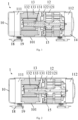
Fig. 1 is a sectional view of the structure of a compressor according to an embodiment; -
Fig. 2 is a sectional view of the structure of a compressor according to another embodiment; -
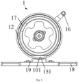
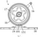
Fig. 3 is a schematic view of the structure of a compressor according to an embodiment; -
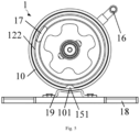
Fig. 4 is a schematic view of the structure of a compressor according to another embodiment; -
Fig. 5 is a schematic view of the structure of a compressor according to another embodiment; -
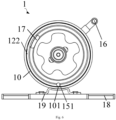
Fig. 6 is a schematic view of the structure of a compressor according to another embodiment; -
Fig. 7 is a schematic view of the structure of a compressor according to another embodiment; -
Fig. 8 is a schematic view of the structure of a compressor according to another embodiment; -
Fig. 9 is a view of a simulation curve of the airflow volume in an oil return channel in a compressor according to an embodiment; and -
Fig. 10 is a histogram of test data of the oil circulation rate of a compressor according to an embodiment. - Wherein the correspondence between the reference numerals and the component names in
Figs. 1 to 8 is:
1 compressor, 10 shell, 101 first shell, 11 cavity, 111 first cavity, 112 second cavity, 12 compression assembly, 121 air cylinder, 122 main bearing, 13 motor, 131 crankshaft, 132 rotor, 133 stator, 134 interval, 14 oil sump, 15 oil return channel, 151 oil inlet, 16 exhaust pipe, 17 airflow channel, 18 base, 19 mounting rack. - In order that the above objects, features, and advantages of the present application may be more clearly understood, the present application will be described in further detail with reference to the accompanying drawings and preferred embodiments.
- In the following description, many specific details are set forth in order to fully understand the present application. However, the present application can also be implemented in other ways different from those described herein.
- A
compressor 1 and a refrigeration device according to some embodiments of the present invention are described below with reference toFig. 1 to Fig. 10 . - According to a first aspect of the present invention, a
compressor 1 is provided, as shown inFig. 1 and Fig. 2 , and thecompressor 1 comprises ashell 10, acompression assembly 12, amotor 13, anoil sump 14 and anoil return channel 15. Wherein, theshell 10 constructs acavity 11, one part of thecompression assembly 12 is fixedly connected with theshell 10 and located in thecavity 11, and thecavity 11 is divided into afirst cavity 111 and asecond cavity 112 by thecompression assembly 12. One part of themotor 13 is arranged in thefirst cavity 111, theoil sump 14 is arranged in thesecond cavity 112, theoil return channel 15 is arranged in thecompression assembly 12, and is configured to communicate thefirst cavity 111 and thesecond cavity 112. The part of theshell 10 located below a central axis of themotor 13 is afirst shell 101, theoil return channel 15 is provided with anoil inlet 151 facing thefirst cavity 111, and theoil inlet 151 has a dividing line parallel to a horizontal plane where the central axis of themotor 13 is located. The oil inlet is divided into two areas by the dividing line, the dividing line has two sides, i.e., a side close to the central axis of themotor 13 and a side departing from the central axis of themotor 13, and an oil through area is located at the side of the dividing line departing from the central axis of themotor 13. Wherein, a distance between the dividing line and a inner-side wall of thefirst shell 101 is a first relative distance, the first relative distance is greater than Omm and less than or equal to 12% of a inner diameter of theshell 10, and an area of the oil through area is greater than or equal to 90% of an area of theoil inlet 151 and less than or equal to the area of theoil inlet 151. - The
compressor 1 comprises ashell 10, acompression assembly 12, amotor 13, anoil sump 14 and anoil return channel 15, wherein, theshell 10 is a sealedshell 10, and a part of thecompression assembly 12 is fixedly connected with theshell 10. Specifically, a part of thecompression assembly 12 can be fixedly connected with theshell 10 through a welding method, thereby ensuring a reliable connecting performance between thecompression assembly 12 and theshell 10. Thecompression assembly 12 is arranged in thecavity 11 and divides thecavity 11 into afirst cavity 111 and asecond cavity 112, thefirst cavity 111 is located at the left side of thecompression assembly 12, and thesecond cavity 112 is located at the right side of thecompression assembly 12, wherein a part of themotor 13 is located in thefirst cavity 111, theoil sump 14 is disposed in thesecond cavity 112, and a lubricating oil is stored in theoil sump 14. When thecompressor 1 works, thecompression assembly 12 can compress a refrigerant, and a portion of compressed refrigerant air can be exhausted through an exhaust structure provided on theshell 10, and the other portion of the compressed refrigerant air can enter thefirst cavity 111 and cool themotor 13, and then, the refrigerant can enter thesecond cavity 112 and is exhausted through the exhaust structure. According to the present invention, through disposing theoil return channel 15 in thecompression assembly 12, the lubricating oil in theoil sump 14 can communicate through theoil return channel 15. When the refrigerant enters thefirst cavity 111, the pressure in thefirst cavity 111 rises, and under the effect of the pressure, the lubricating oil in thefirst cavity 111 can enter thesecond cavity 112 through theoil return channel 15. This design has a simple and reasonable structure and can improve the recovery efficiency of the lubricating oil, so that the fluctuation of the oil level in theoil sump 14 is relatively stable, and the oil circulation ratio of thecompressor 1 is further lowered, so that theoil sump 14 can provide a sufficient volume of oil for thecompressor 12, thereby further improving the reliability and the energy efficiency grade of thecompressor 1. No matter what the working conditions of thecompressor 1 are, the oil in the cavity of themotor 13 can return to the oil cavity through theoil return channel 15 in thecompression assembly 12, the oil supply from theoil sump 14 to the compression assembly is ensured, and the reliability of the oil stored in the oil cavity is ensured, and therefore, the oil circulation ratio is decreased, and the performance of thecompressor 1 is improved. - In addition, the lubricating oil in the
oil channel 15 can also enter the interior of thecompression assembly 12 to lubricate thecompression assembly 12, and thus the operation of thecompressor 1 can be smoother. Specifically, thecompressor 1 is a horizontal compressor. - Further, as shown in
Fig. 3 , theshell 10 is divided into afirst shell 101 and asecond shell 10 connected with thefirst shell 101, and both thefirst shell 101 and thesecond shell 10 extend along the central axis of themotor 13. When theshell 10 is in a cylindrical shape, both thefirst shell 101 and thesecond shell 10 are partial arc segments. Wherein, thefirst shell 101 is located under the central axis of themotor 13. When the horizontal compressor is arranged horizontally on the ground, the outer-side wall of thefirst shell 101 contacts the ground. Wherein, theoil return channel 15 has anoil inlet 151 facing thefirst cavity 111 and an oil outlet facing thesecond cavity 112, and the lubricating oil in thefirst cavity 111 enters theoil return channel 15 through theoil inlet 151 and is discharged to theoil sump 14 through the oil outlet. In the working process of thecompressor 1, the overall pressure in thefirst cavity 111 is higher than the pressure in thesecond cavity 112, and under the effect of a pressure difference, the lubricating oil in thefirst cavity 111 can be pressurized into thesecond cavity 112 through theoil return channel 15. However, when thecompressor 1 is in a working condition of a high rotation speed or a low-pressure ratio, the large flow volume in thecompressor 1 and the large pressure difference between the two sides of thecompression assembly 12 may easily render the circumstance that the oil level in thefirst cavity 111 is lower than theoil inlet 151 of the oil return channel. At this moment, under the effect of the pressure difference, the refrigerant can also enter thesecond cavity 112 through theoil return channel 15, and form lots of bubbles in the lubricating oil in theoil sump 14, which results in a violent fluctuation of the oil level in theoil sump 14, and further renders the increasing of oil circulation ratio of thecompressor 1, so that the performance of thecompressor 1 is lowered. - As shown in
Fig. 9 andFig. 10 , through lots of experiments and observations, it is found that the distance between the dividing line and the inner-side wall of thefirst shell 101 is a first relative distance H1, and the oil circulation rate in high frequency (bad) working conditions can be greatly improved when the first relative distance H1 satisfies 0mm<H1≤10mm. The ventilation condition of theoil sump 14 can be effectively improved if it is difficult to expose theoil inlet 151 of theoil return channel 15 in the refrigerant, thereby reducing the oil circulation ratio. - Specifically, as shown in
Fig. 9 , in a simulation experiment, the distance H1 between the dividing line in theoil inlet 151 and the inner-side wall of thefirst shell 101 of thecompressor 1 is set as a variable, and thus three groups of comparative experiments are formed, while the other operating parameters of thecompressor 1 are the same, and the operating parameters of thecompressor 1 specifically comprise a suction temperature of -1°C, a suction pressure of 0.38MPa, an exhaust temperature of 70°C, an exhaust pressure of 1.53MPa, and a rotating speed of 60Hz. Wherein, when H1=22.3mm, referring to curve C1, it can be seen that the airflow volume (i.e., the air flow of the refrigerant air) in theoil return channel 15 presents a regular fluctuation within a certain operating period, that is, at this moment, the refrigerant air exists in theoil return channel 15, which will affect the stability of the oil level of the lubricating oil in theoil sump 14. When the first relative distance H1 is reduced to 17mm, referring to curve C2, it can be seen that a portion of the refrigerant air exists in theoil return channel 15, however, when the first relative distance H1=10mm, at this moment, referring to curve C3, it can be seen that the airflow volume in theoil return channel 15 tends to be 0, that is, when the distance between the dividing line of theoil inlet 151 of theoil return channel 15 and the inner-side wall of thefirst shell 101 satisfies 0mm<H1≤10mm, it is difficult to expose theoil inlet 151 of theoil return channel 15 in the refrigerant, thereby effectively improving the ventilation condition of theoil sump 14, and further reducing the oil circulation ratio, and greatly improving the oil circulation rate in high frequency (bad) working conditions. - Referring to
Fig. 10 , it can be seen that, when the operation frequency of thecompressor 1 is 60Hz, the distance H1 between the dividing line of theoil inlet 151 of theoil return channel 15 and the inner-side wall of thefirst shell 101 is reduced, and then the oil circulation rate of thecompressor 1 can be reduced slightly. When the operation frequency of thecompressor 1 is 90Hz, and when the H1 is reduced, it can be found that the oil circulation rate of thecompressor 1 is reduced greatly. When H1=22.3mm, the oil circulation rate of thecompressor 1 is 4.9, when H1=10mm, the oil circulation rate of thecompressor 1 is reduced to 1.42, and therefore, reducing the distance H1 between the dividing line of theoil inlet 151 of theoil return channel 15 and the inner-side wall of thefirst shell 101 can greatly improve the oil circulation rate of thecompressor 1 in high frequency (bad) working conditions. - When the first relative distance H1 and the inner diameter of the
shell 10 satisfy the abovementioned relation, it is difficult to expose theoil inlet 151 of theoil return channel 15 in the refrigerant, and this can effectively improve the ventilation condition in theoil sump 14, and then lower the oil circulation ratio of the compressor. Further, the area of the oil through area is greater than or equal to 90% of the area of theoil inlet 151 and less than or equal to the area of theoil inlet 151, and this can further ensure that the lubricating oil flows from theoil inlet 151 to theoil sump 14. - When the area of the oil through area is equal to the area of the
oil inlet 151, the dividing line is located at the highest point of the oil inlet 151 (the highest point refers to the highest point in theoil inlet 151 close to the horizontal plane where the central axis of themotor 13 is located). When the area of the oil through area is less than the area of theoil inlet 151 and greater than or equal to 90% of the area of theoil inlet 151, the dividing line can divide theoil inlet 151 into two areas, wherein one is an oil through area located on the side of the dividing line departing from the central axis of the motor, and the lubricating oil can enter theoil sump 14 through the oil through area. - It should be explained that, when the dividing line is not located above the
first shell 101, the distance between the dividing line and the inner-side wall of thefirst shell 101 is the distance between the dividing line and the plane where the inner-side wall of thefirst shell 101 is located. - Specifically, the
oil return channel 15 is located under the horizontal plane where the central axis of themotor 13 is located, the lubricating oil is deposited on the bottom of thecavity 11 under the effect of gravity, and theoil return channel 15 located in the bottom can help the flow of the lubricating oil. - Further, the
oil return channel 15 presents a flaring shape in the direction of the central axis of themotor 13, and then, the area of the oil outlet is greater than the area of theoil inlet 151. Theoil return channel 15 can also have equivalent cross sections in the direction of the central axis of themotor 13, and a good oil circulation rate can be achieved as long as the distance between theoil inlet 151 of theoil return channel 15 and thefirst shell 101 satisfies the abovementioned relation. - Further, the first relative distance is greater than Omm and less than or equal to 7mm.
- In the embodiment, the highest point of the
oil inlet 151 in theoil return channel 15 can be further lowered if the first relative distance H1 satisfies 0mm<H1≤7mm, so that it is more difficult to expose theoil inlet 151 in the refrigerant, thereby effectively improving the ventilation condition of theoil sump 14, and further reducing the oil circulation ratio. - Further, as shown in
Fig. 3 , theoil inlet 151 has an apex away from the horizontal plane where the central axis of themotor 13 is located, a distance between the apex and the inner-side wall of thefirst shell 101 is a second relative distance, and the second relative distance is greater than or equal to Omm and less than or equal to 3mm. - In the embodiment, as shown in
Fig. 4 andFig. 5 , theoil inlet 151 has an apex away from the horizontal plane where the central axis of themotor 13 is located, the distance between the apex and the inner-side wall of thefirst shell 101 is a second relative distance. When theoil inlet 151 is a closed opening, as shown inFig. 6 andFig. 7 , the second relative distance H2 is greater than Omm and less than or equal to 3mm, that is, the inner-side wall of thecompression assembly 12 which constitutes theoil inlet 151 and the outer-side wall of thecompression assembly 12 are independent from each other, and they do not have any connection relation. When theoil inlet 151 is a non-closed opening, as shown inFig. 4 andFig. 5 , the second relative distance H2 is equal to 0mm, and at this moment, the outer-side wall of thecompression assembly 12 is connected with the inner-side wall of thecompression assembly 12 which constitutes theoil inlet 151. Based on the conditions that the dividing line and the inner-side wall of thefirst shell 101 satisfy 0mm<H1≤10mm, and the distance between the upper apex of theoil inlet 151 and the inner-side wall of thefirst shell 101 satisfies 0mm<H2≤3mm, the dividing line on theoil inlet 151 and the apex (the lowest point in a gravity direction) on theoil inlet 151 are restricted, and therefore, in a precondition of ensuring the flow effect of the lubricating oil, so that the ventilation condition of theoil sump 14 can be effectively improved as it is difficult to expose theoil inlet 151 of theoil return channel 15 in the refrigerant, and the oil circulation ratio is further reduced. - Further, a part of the
compression assembly 12 is concaved towards a direction close to the central axis of themotor 13, so as to form theoil return channel 15. - In the embodiment, a part of the
compression assembly 12 is concaved towards a direction close to the central axis of themotor 13, so as to form theoil return channel 15, i.e., theoil return channel 15 has anoil inlet 151 and an oil outlet along the axis of themotor 13. Meanwhile, theoil return channel 15 also has an opening facing theshell 10, and then, since the part of thecompression assembly 12 which is provided with theoil return channel 15 is fixedly connected to theshell 10, the second relative distance H2 between the apex on theoil inlet 151 and the inner-side wall of thefirst shell 101 is 0mm. Further, a projection of theoil return channel 15 on the cross section of thecrankshaft 131 of themotor 13 is in a circular shape, a triangular shape or a polygonal shape. - What is different from the
abovementioned embodiment 1 is that the specific structure of themotor 13 is described in the present embodiment, wherein themotor 13 comprises acrankshaft 131, arotor 132 and astator 133, wherein a first end of thecrankshaft 131 is located in thefirst cavity 111, and a second end of thecrankshaft 131 is connected with thecompression assembly 12. Therotor 132 is sleeved on the first end of thecrankshaft 131, thestator 133 is sleeved on an outer-side wall of therotor 132, and aninterval 134 is formed between at least a part of an outer-side wall of thestator 133 and the inner-side wall of theshell 10. Wherein, a sectional area of theinterval 134 on a cross section of thecrankshaft 131 is a first sectional area, a sectional area of theoil return channel 15 on a cross section of thecrankshaft 131 is a second sectional area, and the second sectional area is less than or equal to 30% of the first sectional area. - In the embodiment, as shown in
Fig. 8 , the first end of thecrankshaft 131 is located in thefirst cavity 111, and adapted and connected with therotor 132 and thestator 133 of themotor 13. The second end of thecrankshaft 131 is connected with thecompression assembly 12, therotor 132 is sleeved on the first end of thecrankshaft 131, and therotor 132 rotates to drive thecrankshaft 131 to move, thereby further achieving the moving of thecompression assembly 12. Thestator 133 is sleeved on an outer-side wall of therotor 132, and aninterval 134 is formed between at least a part of an outer-side wall of thestator 133 and the inner-side wall of theshell 10, wherein the number of theintervals 134 is at least one. The cross section of thecrankshaft 131 is a section which is perpendicular to the axial direction of thecrankshaft 131. The sectional area of theintervals 134 on the cross section of thecrankshaft 131 is the first sectional area, while the sectional area of theoil return channel 15 on the cross section of thecrankshaft 131 is the second sectional area, the second sectional area is less than or equal to 30% of the first sectional area. When the sectional areas of theoil return channel 15 and theintervals 134 on the cross section of thecrankshaft 131 satisfy the above relation, the lubricating oil in thefirst cavity 111 can flow to theoil return channel 15 through theintervals 134, thereby ensuring the smooth circulation of the lubricating oil in thefirst cavity 111, theoil return channel 15 and thesecond cavity 112, and thus the ventilation condition of the oil sump can be improved effectively as it is difficult to expose theoil inlet 151 of theoil return channel 15 in the refrigerant, thereby further reducing the oil circulation ratio. - Further, the number of the
intervals 134 is at least two, and the first sectional area is a sum of the sectional areas of the at least twointervals 134, the number of theoil return channels 15 is at least two, and the second sectional area is a sum of the sectional areas of the at least twooil return channels 15. - In the embodiment, the number of the
intervals 134 is multiple, and the first sectional area is a sum of the sectional areas of a plurality ofintervals 134, the number of theoil return channels 15 is multiple, and the second sectional area is a sum of the sectional areas of a plurality ofoil return channels 15. If the sum of the sectional areas of themultiple intervals 134 and the sum of the sectional areas of the multipleoil return channels 15 satisfy the above relation, it can be ensured that the lubricating oil can circulate smoothly in thefirst cavity 111, theoil return channel 15 and thesecond cavity 112. - What is different from the abovementioned embodiments is that the specific structure of the
compression assembly 12 is described in the present embodiment, and further, thecompression assembly 12 comprises anair cylinder 121 and amain bearing 122. Themain bearing 122 is provided at a side of theair cylinder 121 facing themotor 13, and a part of themotor 13 penetrates themain bearing 122 and connects theair cylinder 121. Wherein, one of themain bearing 122 and theair cylinder 121, which is fixedly connected with theshell 10, is a fastener, and theoil return channel 15 is provided on the fastener. - In the embodiment, the
compression assembly 12 comprises anair cylinder 121 and amain bearing 122. Themain bearing 122 is provided at a side of theair cylinder 121 facing themotor 13, the second end of thecrankshaft 131 penetrates themain bearing 122 and connects theair cylinder 121. Wherein, themain bearing 122 can be fixedly connected to the inner-side wall of theshell 10 through welding, and theair cylinder 121 can also be fixedly connected to the inner-side wall of theshell 10 through welding, and the fixed connection between themain bearing 122 or thecylinder 121 and theshell 10 can be selected according to actual assembling needs. If themain bearing 122 is welded to theshell 10, theair cylinder 121 is not fixedly connected with theshell 10, and at this moment, theoil return channel 15 is disposed on themain bearing 122, the lubricating oil will enter into theoil return channel 15 from thefirst cavity 111 through theoil inlet 15, and flow to theoil sump 14 through the gap between theair cylinder 121 and theshell 10. On the contrary, if theair cylinder 121 is fixedly connected with theshell 10, the lubricating oil can enter theoil return channel 15 from thefirst cavity 111 through the gap between themain bearing 122 and theshell 10, and then enter theoil sump 14. - Further, the
compressor 1 further comprises anexhaust pipe 16 and anairflow channel 17, wherein theexhaust pipe 16 is provided on theshell 10 corresponding to thecompression assembly 12, theairflow channel 17 is provided on thecompression assembly 12, and theairflow channel 17, thefirst cavity 111 and theexhaust pipe 16 are communicated with each other. - In the embodiment, when the
compressor 1 works, thecompression assembly 12 can pressurize the refrigerant, a portion of the compressed refrigerant air can be exhausted directly through theexhaust pipe 16, the other portion of the compressed refrigerant air can enter thefirst cavity 111 through theairflow channel 17 and cool themotor 13, and then, the refrigerant can enter thesecond cavity 112 and is exhausted through theexhaust pipe 16. - Further, the
compressor 1 further comprises abase 18 and a mountingrack 19, and the mountingrack 19 is connected to a side of the base 18 facing theshell 10, and the mountingrack 19 is adapted and connected with theshell 10. - In the embodiment, the
base 18 can be parallel to thecrankshaft 131, i.e., theshell 10 is disposed on thebase 18 horizontally. The base 18 can also be disposed at a certain angle with thecrankshaft 131, i.e., theshell 10 is tilted on thebase 18. When theshell 10 is disposed on thebase 18, the central axis of themotor 10 has a horizontal plane where it is located. When theshell 10 is tilted on thebase 18, the central axis is at a certain angle with respect to the horizontal plane, and then, thebase 18 can be tilted fixedly on the horizontal bottom, so that the central axis (crankshaft 131) of themotor 13 is parallel to the horizontal plane, and then the position relation between theoil inlet 151 in thecompression assembly 12 of thecompressor 1 and thefirst shell 101 should also satisfy the above relation. - According to the second aspect of the present invention, a refrigeration device is provided, and the refrigeration device comprises a
compressor 1 provided according to any one of the above designs. - The refrigeration device provided by the present invention comprises the
compressor 1 provided according to any one of the above designs, and thus has all the beneficial effects of the compressor, which will not be repeated herein. - Further, the refrigeration device further comprises a housing, a mounting cavity is formed in the housing, the
compressor 1 is connected with the housing and located in the mounting cavity, and thecompressor 1, through the protection of the housing, will not be affected by external environment, thereby ensuring the accurate operation of thecompressor 1. - Further, the refrigeration device can be home appliance devices such as a refrigerator and an air conditioner.
- In the present application, the term "a plurality of" refers to two or more, unless explicitly defined otherwise. The terms such as "installation", "connected", "connecting", "fixation" and the like shall be understood in broad sense, and for example, "connecting" may be a fixed connection, a detachable connection, or an integral connection; "connected" may be directly connected, or indirectly connected through an intermediary. The specific meaning of the above terms in the present application will be understood by those of ordinary skills in the art, as the case may be.
- In the illustration of the description, the illustration of the terms of "one embodiment", "some embodiments", "specific embodiment", etc. means that the specific features, structures, materials, or characteristics described in conjunction with the embodiments or examples are included in at least one embodiment or example.
- In this description, schematic representations of the above terms do not necessarily refer to the same embodiment or example. Moreover, the specific features, structures, materials, or characteristics described may be combined in any suitable manner in any one or more embodiments or examples.
- The foregoing is only a preferred embodiment and is not intended to limit the present application.
Claims (10)
- A compressor (1), comprising:a shell (10), constructing a cavity (11);a compression assembly (12), wherein one part of the compression assembly (12) is fixedly connected with the shell (10) and located in the cavity (11), and the cavity (11) is divided into a first cavity (111) and a second cavity (112) by the compression assembly (12);a motor (13), wherein one part of the motor (13) is arranged in the first cavity (111), and the part of the shell (10) located below a central axis of the motor (13) is a first shell (101); and wherein the motor (13) comprises:a crankshaft (131), wherein a first end of the crankshaft (131) is located in the first cavity (111), and a second end of the crankshaft (131) is connected with the compression assembly (12);a rotor (132), sleeved on the first end of the crankshaft (131); anda stator (133), sleeved on an outer-side wall of the rotor (132), wherein an interval (134) is formed between at least a part of an outer-side wall of the stator (133) and the inner-side wall of the shell (10),an oil sump (14), being arranged in the second cavity (112); andan oil return channel (15), being arranged in the compression assembly (12), and configured to communicate the first cavity (111) and the second cavity (112),wherein the oil return channel (15) is provided with an oil inlet (151) facing the first cavity (111), and the oil inlet (151) has a dividing line parallel to a horizontal plane where the central axis of the motor (13) is located,a distance between the dividing line and an inner-side wall of the first shell (101) is a first relative distance,the oil inlet (151) comprises an oil through area which is located at one side the dividing line departing from the central axis of the motor (13), and an area of the oil through area is greater than or equal to 90% of an area of the oil inlet (151) and less than or equal to the area of the oil inlet (151),characterised in that the first relative distance is greater than Omm and less than or equal to 12% of an inner diameter of the shell (10),a sectional area of the interval (134) on a cross section of the crankshaft (131) is a first sectional area, a sectional area of the oil return channel (15) on a cross section of the crankshaft (131) is a second sectional area, and the second sectional area is less than or equal to 30% of the first sectional area.
- The compressor (1) according to claim 1, wherein,
the first relative distance is greater than Omm and less than or equal to 10mm. - The compressor (1) according to claim 1, wherein,
the first relative distance is greater than Omm and less than or equal to 7mm. - The compressor (1) according to claim 1, wherein,
the oil inlet (151) has an apex away from a horizontal plane where the central axis of the motor (13) is located, a distance between the apex and the inner-side wall of the first shell (101) is a second relative distance, and the second relative distance is greater than or equal to Omm and less than or equal to 3mm. - The compressor (1) according to claim 4, wherein,
a part of the compression assembly (12) is concaved towards a direction close to the central axis of the motor (13), so as to form the oil return channel (15). - The compressor (1) according to claim 1, wherein,the number of the intervals (134) is at least two, and the first sectional area is a sum of the sectional areas of the at least two intervals (134),the number of the oil return channels (15) is at least two, and the second sectional area is a sum of the sectional areas of the at least two oil return channels (15).
- The compressor (1) according to any one of claims 1 to 5, wherein,
the compression assembly (12) comprises:an air cylinder (121); anda main bearing (122), provided at a side of the air cylinder (121) facing the motor (13), wherein a part of the motor (13) penetrates the main bearing (122) and connects the air cylinder (121),wherein one of the main bearing (122) and the air cylinder (121), which is fixedly connected with the shell (10), is a fastener, and the oil return channel (15) is provided on the fastener. - The compressor (1) according to any one of claims 1 to 5, further comprising:an exhaust pipe (16), provided on the shell (10) corresponding to the compression assembly (12); andan airflow channel (17), provided on the compression assembly (12), wherein the airflow channel (17), the first cavity (111) and the exhaust pipe (16) are communicated with each other.
- The compressor (1) according to any one of claims 1 to 5, further comprising:a base (18); anda mounting rack (19), connected to a side of the base (18) facing the shell (10), wherein the mounting rack (19) is adapted and connected with the shell (10).
- A refrigeration device, comprising:a housing, comprising a mounting cavity; anda compressor (1) according to any one of claims 1 to 9, wherein the compressor (1) is connected with the housing and located in the mounting cavity.
Applications Claiming Priority (2)
| Application Number | Priority Date | Filing Date | Title |
|---|---|---|---|
| CN202010613519.2A CN111828326B (en) | 2020-06-30 | 2020-06-30 | Compressor and refrigerating device |
| PCT/CN2020/136363 WO2022001019A1 (en) | 2020-06-30 | 2020-12-15 | Compressor and refrigerating device |
Publications (3)
| Publication Number | Publication Date |
|---|---|
| EP3964712A1 EP3964712A1 (en) | 2022-03-09 |
| EP3964712A4 EP3964712A4 (en) | 2022-08-10 |
| EP3964712B1 true EP3964712B1 (en) | 2025-03-05 |
Family
ID=72900722
Family Applications (1)
| Application Number | Title | Priority Date | Filing Date |
|---|---|---|---|
| EP20937175.6A Active EP3964712B1 (en) | 2020-06-30 | 2020-12-15 | Compressor and refrigerating device |
Country Status (5)
| Country | Link |
|---|---|
| US (1) | US11971036B2 (en) |
| EP (1) | EP3964712B1 (en) |
| CN (1) | CN111828326B (en) |
| ES (1) | ES3028111T3 (en) |
| WO (1) | WO2022001019A1 (en) |
Families Citing this family (3)
| Publication number | Priority date | Publication date | Assignee | Title |
|---|---|---|---|---|
| CN111828326B (en) | 2020-06-30 | 2022-03-01 | 广东美芝精密制造有限公司 | Compressor and refrigerating device |
| WO2023246195A1 (en) * | 2022-06-22 | 2023-12-28 | 安徽威灵汽车部件有限公司 | Electric compressor, air conditioning system and vehicle |
| CN117212170B (en) * | 2023-10-30 | 2025-11-04 | 广东美芝制冷设备有限公司 | Crankshaft assembly, compressor and refrigeration equipment |
Family Cites Families (14)
| Publication number | Priority date | Publication date | Assignee | Title |
|---|---|---|---|---|
| BR8900780A (en) * | 1989-02-17 | 1990-10-02 | Brasil Compressores Sa | LUBRICATION SYSTEM FOR HORIZONTAL AXLE ROTATING HERMETIC COMPRESSOR |
| US5222885A (en) * | 1992-05-12 | 1993-06-29 | Tecumseh Products Company | Horizontal rotary compressor oiling system |
| JP2003269356A (en) * | 2002-03-18 | 2003-09-25 | Sanyo Electric Co Ltd | Horizontal type rotary compressor |
| CN100513793C (en) * | 2003-12-12 | 2009-07-15 | 乐金电子(天津)电器有限公司 | Oil supplying device in horizontal rotating type compressor |
| CN201202646Y (en) * | 2008-05-22 | 2009-03-04 | 浙江博阳压缩机有限公司 | Horizontal rotary compressor |
| JP5150564B2 (en) * | 2009-06-22 | 2013-02-20 | 日立アプライアンス株式会社 | Horizontal hermetic compressor |
| CN201982306U (en) * | 2010-12-31 | 2011-09-21 | 珠海格力电器股份有限公司 | Horizontal rotary compressor |
| CN102953999A (en) * | 2011-08-26 | 2013-03-06 | 乐金电子(天津)电器有限公司 | Rotary compressor |
| CN204003456U (en) * | 2014-04-16 | 2014-12-10 | 广东美芝制冷设备有限公司 | Horizontal compressor |
| CN106894999B (en) * | 2015-12-21 | 2018-09-11 | 珠海凌达压缩机有限公司 | Horizontal compressor and refrigerating device |
| CN209654233U (en) * | 2019-02-21 | 2019-11-19 | 浙江博阳压缩机有限公司 | A kind of horizontal rotary compressor |
| CN209523874U (en) * | 2019-02-28 | 2019-10-22 | 广东美芝制冷设备有限公司 | Low-pressure shell double-cylinder horizontal rotary compressor and refrigeration cycle device having same |
| CN110513293B (en) * | 2019-09-05 | 2025-01-07 | 珠海凌达压缩机有限公司 | Oil-draining and pressure-releasing structure, scroll compressor and air conditioner |
| CN111828326B (en) * | 2020-06-30 | 2022-03-01 | 广东美芝精密制造有限公司 | Compressor and refrigerating device |
-
2020
- 2020-06-30 CN CN202010613519.2A patent/CN111828326B/en active Active
- 2020-12-15 ES ES20937175T patent/ES3028111T3/en active Active
- 2020-12-15 EP EP20937175.6A patent/EP3964712B1/en active Active
- 2020-12-15 WO PCT/CN2020/136363 patent/WO2022001019A1/en not_active Ceased
-
2021
- 2021-12-23 US US17/561,149 patent/US11971036B2/en active Active
Also Published As
| Publication number | Publication date |
|---|---|
| EP3964712A4 (en) | 2022-08-10 |
| EP3964712A1 (en) | 2022-03-09 |
| US11971036B2 (en) | 2024-04-30 |
| WO2022001019A1 (en) | 2022-01-06 |
| CN111828326A (en) | 2020-10-27 |
| ES3028111T3 (en) | 2025-06-18 |
| US20220112897A1 (en) | 2022-04-14 |
| CN111828326B (en) | 2022-03-01 |
Similar Documents
| Publication | Publication Date | Title |
|---|---|---|
| US11971036B2 (en) | Compressor and refrigeration device with an oil return channel having a first relative distance to an inner-side wall | |
| US8801397B2 (en) | Compressor | |
| CN1297749C (en) | Vorticity compression pump | |
| US9885357B2 (en) | Hermetic compressor and vapor compression-type refrigeration cycle device including the hermetic compressor | |
| CN101520046B (en) | Closed compressor and refrigerating circulation device | |
| US7748968B2 (en) | Two-cylinder rotary compressor with suction pipes | |
| US9651047B2 (en) | Compressor having a partitioned discharge chamber | |
| EP1203159B1 (en) | Compressor | |
| US20170089624A1 (en) | Hermetic compressor and vapor compression-type refrigeration cycle device including the hermetic compressor | |
| CN113550908B (en) | Rotor components and compressors | |
| US20170067467A1 (en) | Scroll compressor | |
| CN116517838A (en) | Compressor and refrigeration equipment | |
| CN218581813U (en) | Compressor | |
| US7484945B2 (en) | Compressor for refrigerator-freezer having a porous member | |
| CN207111430U (en) | Crankshaft, rolling rotor micro compressor and refrigeration system | |
| US10851787B2 (en) | Compressor bearing housing drain | |
| CN108443151B (en) | Double-stage differential pressure oil supply horizontal rotary compressor | |
| CN206246358U (en) | Screw compressor and refrigeration system | |
| CN209654233U (en) | A kind of horizontal rotary compressor | |
| EP1830069B1 (en) | Rotary compressor | |
| CN118148924B (en) | Scroll compressor and air conditioner | |
| CN210135087U (en) | Compressor with oil distribution member | |
| KR20210000291A (en) | Compressor | |
| CN2793371Y (en) | Closed compressor for reducing take-out oil | |
| CN223689938U (en) | Compressor and refrigeration equipment |
Legal Events
| Date | Code | Title | Description |
|---|---|---|---|
| STAA | Information on the status of an ep patent application or granted ep patent |
Free format text: STATUS: UNKNOWN |
|
| STAA | Information on the status of an ep patent application or granted ep patent |
Free format text: STATUS: THE INTERNATIONAL PUBLICATION HAS BEEN MADE |
|
| PUAI | Public reference made under article 153(3) epc to a published international application that has entered the european phase |
Free format text: ORIGINAL CODE: 0009012 |
|
| STAA | Information on the status of an ep patent application or granted ep patent |
Free format text: STATUS: REQUEST FOR EXAMINATION WAS MADE |
|
| 17P | Request for examination filed |
Effective date: 20211201 |
|
| AK | Designated contracting states |
Kind code of ref document: A1 Designated state(s): AL AT BE BG CH CY CZ DE DK EE ES FI FR GB GR HR HU IE IS IT LI LT LU LV MC MK MT NL NO PL PT RO RS SE SI SK SM TR |
|
| A4 | Supplementary search report drawn up and despatched |
Effective date: 20220708 |
|
| RIC1 | Information provided on ipc code assigned before grant |
Ipc: F25B 31/02 20060101ALI20220704BHEP Ipc: F04B 39/02 20060101ALI20220704BHEP Ipc: F04C 29/02 20060101ALI20220704BHEP Ipc: F04C 29/00 20060101AFI20220704BHEP |
|
| DAV | Request for validation of the european patent (deleted) | ||
| DAX | Request for extension of the european patent (deleted) | ||
| STAA | Information on the status of an ep patent application or granted ep patent |
Free format text: STATUS: EXAMINATION IS IN PROGRESS |
|
| 17Q | First examination report despatched |
Effective date: 20240124 |
|
| RIC1 | Information provided on ipc code assigned before grant |
Ipc: F04C 23/00 20060101ALI20240827BHEP Ipc: F04C 29/02 20060101ALI20240827BHEP Ipc: F04B 39/02 20060101ALI20240827BHEP Ipc: F25B 31/02 20060101ALI20240827BHEP Ipc: F04C 29/00 20060101AFI20240827BHEP |
|
| GRAP | Despatch of communication of intention to grant a patent |
Free format text: ORIGINAL CODE: EPIDOSNIGR1 |
|
| STAA | Information on the status of an ep patent application or granted ep patent |
Free format text: STATUS: GRANT OF PATENT IS INTENDED |
|
| INTG | Intention to grant announced |
Effective date: 20241004 |
|
| GRAS | Grant fee paid |
Free format text: ORIGINAL CODE: EPIDOSNIGR3 |
|
| GRAA | (expected) grant |
Free format text: ORIGINAL CODE: 0009210 |
|
| STAA | Information on the status of an ep patent application or granted ep patent |
Free format text: STATUS: THE PATENT HAS BEEN GRANTED |
|
| AK | Designated contracting states |
Kind code of ref document: B1 Designated state(s): AL AT BE BG CH CY CZ DE DK EE ES FI FR GB GR HR HU IE IS IT LI LT LU LV MC MK MT NL NO PL PT RO RS SE SI SK SM TR |
|
| REG | Reference to a national code |
Ref country code: GB Ref legal event code: FG4D |
|
| REG | Reference to a national code |
Ref country code: CH Ref legal event code: EP |
|
| REG | Reference to a national code |
Ref country code: DE Ref legal event code: R096 Ref document number: 602020047449 Country of ref document: DE |
|
| REG | Reference to a national code |
Ref country code: IE Ref legal event code: FG4D |
|
| REG | Reference to a national code |
Ref country code: ES Ref legal event code: FG2A Ref document number: 3028111 Country of ref document: ES Kind code of ref document: T3 Effective date: 20250618 |
|
| PG25 | Lapsed in a contracting state [announced via postgrant information from national office to epo] |
Ref country code: RS Free format text: LAPSE BECAUSE OF FAILURE TO SUBMIT A TRANSLATION OF THE DESCRIPTION OR TO PAY THE FEE WITHIN THE PRESCRIBED TIME-LIMIT Effective date: 20250605 |
|
| PG25 | Lapsed in a contracting state [announced via postgrant information from national office to epo] |
Ref country code: FI Free format text: LAPSE BECAUSE OF FAILURE TO SUBMIT A TRANSLATION OF THE DESCRIPTION OR TO PAY THE FEE WITHIN THE PRESCRIBED TIME-LIMIT Effective date: 20250305 |
|
| REG | Reference to a national code |
Ref country code: NL Ref legal event code: MP Effective date: 20250305 |
|
| REG | Reference to a national code |
Ref country code: LT Ref legal event code: MG9D |
|
| PG25 | Lapsed in a contracting state [announced via postgrant information from national office to epo] |
Ref country code: NO Free format text: LAPSE BECAUSE OF FAILURE TO SUBMIT A TRANSLATION OF THE DESCRIPTION OR TO PAY THE FEE WITHIN THE PRESCRIBED TIME-LIMIT Effective date: 20250605 |
|
| PG25 | Lapsed in a contracting state [announced via postgrant information from national office to epo] |
Ref country code: HR Free format text: LAPSE BECAUSE OF FAILURE TO SUBMIT A TRANSLATION OF THE DESCRIPTION OR TO PAY THE FEE WITHIN THE PRESCRIBED TIME-LIMIT Effective date: 20250305 |
|
| PG25 | Lapsed in a contracting state [announced via postgrant information from national office to epo] |
Ref country code: LV Free format text: LAPSE BECAUSE OF FAILURE TO SUBMIT A TRANSLATION OF THE DESCRIPTION OR TO PAY THE FEE WITHIN THE PRESCRIBED TIME-LIMIT Effective date: 20250305 |
|
| PG25 | Lapsed in a contracting state [announced via postgrant information from national office to epo] |
Ref country code: GR Free format text: LAPSE BECAUSE OF FAILURE TO SUBMIT A TRANSLATION OF THE DESCRIPTION OR TO PAY THE FEE WITHIN THE PRESCRIBED TIME-LIMIT Effective date: 20250606 Ref country code: BG Free format text: LAPSE BECAUSE OF FAILURE TO SUBMIT A TRANSLATION OF THE DESCRIPTION OR TO PAY THE FEE WITHIN THE PRESCRIBED TIME-LIMIT Effective date: 20250305 |
|
| REG | Reference to a national code |
Ref country code: AT Ref legal event code: MK05 Ref document number: 1773149 Country of ref document: AT Kind code of ref document: T Effective date: 20250305 |
|
| PG25 | Lapsed in a contracting state [announced via postgrant information from national office to epo] |
Ref country code: NL Free format text: LAPSE BECAUSE OF FAILURE TO SUBMIT A TRANSLATION OF THE DESCRIPTION OR TO PAY THE FEE WITHIN THE PRESCRIBED TIME-LIMIT Effective date: 20250305 |
|
| PG25 | Lapsed in a contracting state [announced via postgrant information from national office to epo] |
Ref country code: SE Free format text: LAPSE BECAUSE OF FAILURE TO SUBMIT A TRANSLATION OF THE DESCRIPTION OR TO PAY THE FEE WITHIN THE PRESCRIBED TIME-LIMIT Effective date: 20250305 |
|
| PG25 | Lapsed in a contracting state [announced via postgrant information from national office to epo] |
Ref country code: SM Free format text: LAPSE BECAUSE OF FAILURE TO SUBMIT A TRANSLATION OF THE DESCRIPTION OR TO PAY THE FEE WITHIN THE PRESCRIBED TIME-LIMIT Effective date: 20250305 |
|
| PG25 | Lapsed in a contracting state [announced via postgrant information from national office to epo] |
Ref country code: PT Free format text: LAPSE BECAUSE OF FAILURE TO SUBMIT A TRANSLATION OF THE DESCRIPTION OR TO PAY THE FEE WITHIN THE PRESCRIBED TIME-LIMIT Effective date: 20250707 |
|
| PG25 | Lapsed in a contracting state [announced via postgrant information from national office to epo] |
Ref country code: PL Free format text: LAPSE BECAUSE OF FAILURE TO SUBMIT A TRANSLATION OF THE DESCRIPTION OR TO PAY THE FEE WITHIN THE PRESCRIBED TIME-LIMIT Effective date: 20250305 |
|
| PG25 | Lapsed in a contracting state [announced via postgrant information from national office to epo] |
Ref country code: AT Free format text: LAPSE BECAUSE OF FAILURE TO SUBMIT A TRANSLATION OF THE DESCRIPTION OR TO PAY THE FEE WITHIN THE PRESCRIBED TIME-LIMIT Effective date: 20250305 |
|
| PG25 | Lapsed in a contracting state [announced via postgrant information from national office to epo] |
Ref country code: CZ Free format text: LAPSE BECAUSE OF FAILURE TO SUBMIT A TRANSLATION OF THE DESCRIPTION OR TO PAY THE FEE WITHIN THE PRESCRIBED TIME-LIMIT Effective date: 20250305 Ref country code: EE Free format text: LAPSE BECAUSE OF FAILURE TO SUBMIT A TRANSLATION OF THE DESCRIPTION OR TO PAY THE FEE WITHIN THE PRESCRIBED TIME-LIMIT Effective date: 20250305 |
|
| PG25 | Lapsed in a contracting state [announced via postgrant information from national office to epo] |
Ref country code: RO Free format text: LAPSE BECAUSE OF FAILURE TO SUBMIT A TRANSLATION OF THE DESCRIPTION OR TO PAY THE FEE WITHIN THE PRESCRIBED TIME-LIMIT Effective date: 20250305 |
|
| PG25 | Lapsed in a contracting state [announced via postgrant information from national office to epo] |
Ref country code: SK Free format text: LAPSE BECAUSE OF FAILURE TO SUBMIT A TRANSLATION OF THE DESCRIPTION OR TO PAY THE FEE WITHIN THE PRESCRIBED TIME-LIMIT Effective date: 20250305 |
|
| PG25 | Lapsed in a contracting state [announced via postgrant information from national office to epo] |
Ref country code: IS Free format text: LAPSE BECAUSE OF FAILURE TO SUBMIT A TRANSLATION OF THE DESCRIPTION OR TO PAY THE FEE WITHIN THE PRESCRIBED TIME-LIMIT Effective date: 20250705 |
|
| REG | Reference to a national code |
Ref country code: DE Ref legal event code: R097 Ref document number: 602020047449 Country of ref document: DE |
|
| PLBE | No opposition filed within time limit |
Free format text: ORIGINAL CODE: 0009261 |
|
| STAA | Information on the status of an ep patent application or granted ep patent |
Free format text: STATUS: NO OPPOSITION FILED WITHIN TIME LIMIT |
|
| PG25 | Lapsed in a contracting state [announced via postgrant information from national office to epo] |
Ref country code: DK Free format text: LAPSE BECAUSE OF FAILURE TO SUBMIT A TRANSLATION OF THE DESCRIPTION OR TO PAY THE FEE WITHIN THE PRESCRIBED TIME-LIMIT Effective date: 20250305 |
|
| PGFP | Annual fee paid to national office [announced via postgrant information from national office to epo] |
Ref country code: IT Payment date: 20251212 Year of fee payment: 6 |
|
| REG | Reference to a national code |
Ref country code: CH Ref legal event code: L10 Free format text: ST27 STATUS EVENT CODE: U-0-0-L10-L00 (AS PROVIDED BY THE NATIONAL OFFICE) Effective date: 20260114 |
|
| PGFP | Annual fee paid to national office [announced via postgrant information from national office to epo] |
Ref country code: TR Payment date: 20251128 Year of fee payment: 6 |
|
| 26N | No opposition filed |
Effective date: 20251208 |
|
| PGFP | Annual fee paid to national office [announced via postgrant information from national office to epo] |
Ref country code: ES Payment date: 20260105 Year of fee payment: 6 |