EP3964694A1 - Seals and methods of making seals - Google Patents
Seals and methods of making seals Download PDFInfo
- Publication number
- EP3964694A1 EP3964694A1 EP21194652.0A EP21194652A EP3964694A1 EP 3964694 A1 EP3964694 A1 EP 3964694A1 EP 21194652 A EP21194652 A EP 21194652A EP 3964694 A1 EP3964694 A1 EP 3964694A1
- Authority
- EP
- European Patent Office
- Prior art keywords
- seal body
- seal
- entropy alloy
- high entropy
- gas turbine
- Prior art date
- Legal status (The legal status is an assumption and is not a legal conclusion. Google has not performed a legal analysis and makes no representation as to the accuracy of the status listed.)
- Granted
Links
Images

Classifications
-
- F—MECHANICAL ENGINEERING; LIGHTING; HEATING; WEAPONS; BLASTING
- F01—MACHINES OR ENGINES IN GENERAL; ENGINE PLANTS IN GENERAL; STEAM ENGINES
- F01D—NON-POSITIVE DISPLACEMENT MACHINES OR ENGINES, e.g. STEAM TURBINES
- F01D11/00—Preventing or minimising internal leakage of working-fluid, e.g. between stages
- F01D11/005—Sealing means between non relatively rotating elements
-
- F—MECHANICAL ENGINEERING; LIGHTING; HEATING; WEAPONS; BLASTING
- F01—MACHINES OR ENGINES IN GENERAL; ENGINE PLANTS IN GENERAL; STEAM ENGINES
- F01D—NON-POSITIVE DISPLACEMENT MACHINES OR ENGINES, e.g. STEAM TURBINES
- F01D11/00—Preventing or minimising internal leakage of working-fluid, e.g. between stages
- F01D11/003—Preventing or minimising internal leakage of working-fluid, e.g. between stages by packing rings; Mechanical seals
-
- B—PERFORMING OPERATIONS; TRANSPORTING
- B22—CASTING; POWDER METALLURGY
- B22F—WORKING METALLIC POWDER; MANUFACTURE OF ARTICLES FROM METALLIC POWDER; MAKING METALLIC POWDER; APPARATUS OR DEVICES SPECIALLY ADAPTED FOR METALLIC POWDER
- B22F10/00—Additive manufacturing of workpieces or articles from metallic powder
- B22F10/20—Direct sintering or melting
- B22F10/25—Direct deposition of metal particles, e.g. direct metal deposition [DMD] or laser engineered net shaping [LENS]
-
- B—PERFORMING OPERATIONS; TRANSPORTING
- B22—CASTING; POWDER METALLURGY
- B22F—WORKING METALLIC POWDER; MANUFACTURE OF ARTICLES FROM METALLIC POWDER; MAKING METALLIC POWDER; APPARATUS OR DEVICES SPECIALLY ADAPTED FOR METALLIC POWDER
- B22F10/00—Additive manufacturing of workpieces or articles from metallic powder
- B22F10/20—Direct sintering or melting
- B22F10/28—Powder bed fusion, e.g. selective laser melting [SLM] or electron beam melting [EBM]
-
- B—PERFORMING OPERATIONS; TRANSPORTING
- B22—CASTING; POWDER METALLURGY
- B22F—WORKING METALLIC POWDER; MANUFACTURE OF ARTICLES FROM METALLIC POWDER; MAKING METALLIC POWDER; APPARATUS OR DEVICES SPECIALLY ADAPTED FOR METALLIC POWDER
- B22F5/00—Manufacture of workpieces or articles from metallic powder characterised by the special shape of the product
- B22F5/009—Manufacture of workpieces or articles from metallic powder characterised by the special shape of the product of turbine components other than turbine blades
-
- B—PERFORMING OPERATIONS; TRANSPORTING
- B23—MACHINE TOOLS; METAL-WORKING NOT OTHERWISE PROVIDED FOR
- B23K—SOLDERING OR UNSOLDERING; WELDING; CLADDING OR PLATING BY SOLDERING OR WELDING; CUTTING BY APPLYING HEAT LOCALLY, e.g. FLAME CUTTING; WORKING BY LASER BEAM
- B23K9/00—Arc welding or cutting
- B23K9/04—Welding for other purposes than joining, e.g. built-up welding
-
- B—PERFORMING OPERATIONS; TRANSPORTING
- B33—ADDITIVE MANUFACTURING TECHNOLOGY
- B33Y—ADDITIVE MANUFACTURING, i.e. MANUFACTURING OF THREE-DIMENSIONAL [3D] OBJECTS BY ADDITIVE DEPOSITION, ADDITIVE AGGLOMERATION OR ADDITIVE LAYERING, e.g. BY 3D PRINTING, STEREOLITHOGRAPHY OR SELECTIVE LASER SINTERING
- B33Y10/00—Processes of additive manufacturing
-
- B—PERFORMING OPERATIONS; TRANSPORTING
- B33—ADDITIVE MANUFACTURING TECHNOLOGY
- B33Y—ADDITIVE MANUFACTURING, i.e. MANUFACTURING OF THREE-DIMENSIONAL [3D] OBJECTS BY ADDITIVE DEPOSITION, ADDITIVE AGGLOMERATION OR ADDITIVE LAYERING, e.g. BY 3D PRINTING, STEREOLITHOGRAPHY OR SELECTIVE LASER SINTERING
- B33Y70/00—Materials specially adapted for additive manufacturing
- B33Y70/10—Composites of different types of material, e.g. mixtures of ceramics and polymers or mixtures of metals and biomaterials
-
- B—PERFORMING OPERATIONS; TRANSPORTING
- B33—ADDITIVE MANUFACTURING TECHNOLOGY
- B33Y—ADDITIVE MANUFACTURING, i.e. MANUFACTURING OF THREE-DIMENSIONAL [3D] OBJECTS BY ADDITIVE DEPOSITION, ADDITIVE AGGLOMERATION OR ADDITIVE LAYERING, e.g. BY 3D PRINTING, STEREOLITHOGRAPHY OR SELECTIVE LASER SINTERING
- B33Y80/00—Products made by additive manufacturing
-
- C—CHEMISTRY; METALLURGY
- C22—METALLURGY; FERROUS OR NON-FERROUS ALLOYS; TREATMENT OF ALLOYS OR NON-FERROUS METALS
- C22C—ALLOYS
- C22C30/00—Alloys containing less than 50% by weight of each constituent
-
- F—MECHANICAL ENGINEERING; LIGHTING; HEATING; WEAPONS; BLASTING
- F16—ENGINEERING ELEMENTS AND UNITS; GENERAL MEASURES FOR PRODUCING AND MAINTAINING EFFECTIVE FUNCTIONING OF MACHINES OR INSTALLATIONS; THERMAL INSULATION IN GENERAL
- F16J—PISTONS; CYLINDERS; SEALINGS
- F16J15/00—Sealings
- F16J15/02—Sealings between relatively-stationary surfaces
- F16J15/06—Sealings between relatively-stationary surfaces with solid packing compressed between sealing surfaces
- F16J15/08—Sealings between relatively-stationary surfaces with solid packing compressed between sealing surfaces with exclusively metal packing
- F16J15/0806—Sealings between relatively-stationary surfaces with solid packing compressed between sealing surfaces with exclusively metal packing characterised by material or surface treatment
-
- F—MECHANICAL ENGINEERING; LIGHTING; HEATING; WEAPONS; BLASTING
- F16—ENGINEERING ELEMENTS AND UNITS; GENERAL MEASURES FOR PRODUCING AND MAINTAINING EFFECTIVE FUNCTIONING OF MACHINES OR INSTALLATIONS; THERMAL INSULATION IN GENERAL
- F16J—PISTONS; CYLINDERS; SEALINGS
- F16J15/00—Sealings
- F16J15/16—Sealings between relatively-moving surfaces
-
- B—PERFORMING OPERATIONS; TRANSPORTING
- B23—MACHINE TOOLS; METAL-WORKING NOT OTHERWISE PROVIDED FOR
- B23K—SOLDERING OR UNSOLDERING; WELDING; CLADDING OR PLATING BY SOLDERING OR WELDING; CUTTING BY APPLYING HEAT LOCALLY, e.g. FLAME CUTTING; WORKING BY LASER BEAM
- B23K2103/00—Materials to be soldered, welded or cut
- B23K2103/08—Non-ferrous metals or alloys
- B23K2103/10—Aluminium or alloys thereof
-
- F—MECHANICAL ENGINEERING; LIGHTING; HEATING; WEAPONS; BLASTING
- F05—INDEXING SCHEMES RELATING TO ENGINES OR PUMPS IN VARIOUS SUBCLASSES OF CLASSES F01-F04
- F05D—INDEXING SCHEME FOR ASPECTS RELATING TO NON-POSITIVE-DISPLACEMENT MACHINES OR ENGINES, GAS-TURBINES OR JET-PROPULSION PLANTS
- F05D2230/00—Manufacture
- F05D2230/20—Manufacture essentially without removing material
- F05D2230/22—Manufacture essentially without removing material by sintering
-
- F—MECHANICAL ENGINEERING; LIGHTING; HEATING; WEAPONS; BLASTING
- F05—INDEXING SCHEMES RELATING TO ENGINES OR PUMPS IN VARIOUS SUBCLASSES OF CLASSES F01-F04
- F05D—INDEXING SCHEME FOR ASPECTS RELATING TO NON-POSITIVE-DISPLACEMENT MACHINES OR ENGINES, GAS-TURBINES OR JET-PROPULSION PLANTS
- F05D2230/00—Manufacture
- F05D2230/20—Manufacture essentially without removing material
- F05D2230/23—Manufacture essentially without removing material by permanently joining parts together
- F05D2230/232—Manufacture essentially without removing material by permanently joining parts together by welding
- F05D2230/234—Laser welding
-
- F—MECHANICAL ENGINEERING; LIGHTING; HEATING; WEAPONS; BLASTING
- F05—INDEXING SCHEMES RELATING TO ENGINES OR PUMPS IN VARIOUS SUBCLASSES OF CLASSES F01-F04
- F05D—INDEXING SCHEME FOR ASPECTS RELATING TO NON-POSITIVE-DISPLACEMENT MACHINES OR ENGINES, GAS-TURBINES OR JET-PROPULSION PLANTS
- F05D2230/00—Manufacture
- F05D2230/30—Manufacture with deposition of material
- F05D2230/31—Layer deposition
-
- F—MECHANICAL ENGINEERING; LIGHTING; HEATING; WEAPONS; BLASTING
- F05—INDEXING SCHEMES RELATING TO ENGINES OR PUMPS IN VARIOUS SUBCLASSES OF CLASSES F01-F04
- F05D—INDEXING SCHEME FOR ASPECTS RELATING TO NON-POSITIVE-DISPLACEMENT MACHINES OR ENGINES, GAS-TURBINES OR JET-PROPULSION PLANTS
- F05D2240/00—Components
- F05D2240/55—Seals
-
- F—MECHANICAL ENGINEERING; LIGHTING; HEATING; WEAPONS; BLASTING
- F05—INDEXING SCHEMES RELATING TO ENGINES OR PUMPS IN VARIOUS SUBCLASSES OF CLASSES F01-F04
- F05D—INDEXING SCHEME FOR ASPECTS RELATING TO NON-POSITIVE-DISPLACEMENT MACHINES OR ENGINES, GAS-TURBINES OR JET-PROPULSION PLANTS
- F05D2250/00—Geometry
- F05D2250/70—Shape
- F05D2250/75—Shape given by its similarity to a letter, e.g. T-shaped
-
- F—MECHANICAL ENGINEERING; LIGHTING; HEATING; WEAPONS; BLASTING
- F05—INDEXING SCHEMES RELATING TO ENGINES OR PUMPS IN VARIOUS SUBCLASSES OF CLASSES F01-F04
- F05D—INDEXING SCHEME FOR ASPECTS RELATING TO NON-POSITIVE-DISPLACEMENT MACHINES OR ENGINES, GAS-TURBINES OR JET-PROPULSION PLANTS
- F05D2300/00—Materials; Properties thereof
- F05D2300/10—Metals, alloys or intermetallic compounds
- F05D2300/17—Alloys
- F05D2300/177—Ni - Si alloys
-
- Y—GENERAL TAGGING OF NEW TECHNOLOGICAL DEVELOPMENTS; GENERAL TAGGING OF CROSS-SECTIONAL TECHNOLOGIES SPANNING OVER SEVERAL SECTIONS OF THE IPC; TECHNICAL SUBJECTS COVERED BY FORMER USPC CROSS-REFERENCE ART COLLECTIONS [XRACs] AND DIGESTS
- Y02—TECHNOLOGIES OR APPLICATIONS FOR MITIGATION OR ADAPTATION AGAINST CLIMATE CHANGE
- Y02P—CLIMATE CHANGE MITIGATION TECHNOLOGIES IN THE PRODUCTION OR PROCESSING OF GOODS
- Y02P10/00—Technologies related to metal processing
- Y02P10/25—Process efficiency
Definitions
- Seals are widely used in various applications to contain a fluid in a desired area of a piece of equipment.
- Many different types of materials can be used to fabricate seals according to many different types of design.
- stationary seals are attached to a fixed component and create a seal with another fixed component or a moving component.
- a seal may move with one component to create a seal with another component hat is fixed or moves. Both moving and stationary seals seals can be subject to wear and other undesirable effects from friction between the seal and a contact surface on a component.
- a tribological and creep resistant system configured to operate at temperatures in excess of 700°C.
- a seal body that extends between a leading edge and a trailing edge.
- a first component contact surface is adjacent the leading edge and a second component contact surface is adjacent the trailing edge.
- the seal body is formed from a high entropy alloy.
- the seal body forms a complete ring.
- system is configured to operate at temperatures up to 900°C.
- a gas turbine engine with the seal body is located radially outward of a core airflow path through the gas turbine engine in a turbine section of the gas turbine engine.
- a gas turbine engine with the seal body is located radially outward of a core airflow path through the gas turbine engine in a high pressure compressor of the gas turbine engine.
- the seal body includes at least one bend.
- the at least one bend includes multiple bends on one of a radially inner side or a radially outer side of the seal body. Only a single bend is on the other of the radially inner side or the radially outer side.
- a first component engages the first component contact surface on the leading edge of the body seal.
- a second component engages the second component contact surface on the trialing edge of the body seal.
- the first component is a vane and the second component is a blade outer air seal.
- a first component defines a groove that seats a radially inner portion of the seal body.
- the seal body defines a piston seal.
- the first component is a mid-turbine frame vane and the groove is located on a radially outer portion of the mid-turbine frame vane.
- the high entropy alloy includes one of MoNbTaW, AlCoCrFeNiTi, or CoCrFeMnNi.
- a method in another exemplary embodiment, includes providing a powdered high entropy alloy.
- the powdered high entropy alloy is formed into a seal body with a heat source.
- the seal body extends between a leading edge and a trailing edge.
- a first component contact surface is adjacent the leading edge and a second component contact surface is adjacent the trailing edge and is configured to operate at temperatures in excess of 700°C.
- the powdered high entropy alloy utilizes a powdered bed of the high entropy alloy.
- Forming the powdered high entropy alloy into the seal body with the heat source includes welding or melting adjacent layers of the high entropy alloy in the powdered bed to form a desired shape of the seal body.
- providing the powdered high entropy alloy includes blowing streams of the powdered high entropy alloy.
- forming the powdered high entropy alloy into a seal body with the heat source includes controlling the heat source to weld or melt the high entropy alloy into a desired shape of the seal body.
- the seal body extends from a leading edge to a trailing edge and includes at least one bend.
- the seal body extends from a leading edge to a trailing edge and defines a piston seal.
- the seal body forms a complete ring of sufficient diameter to surround a core air flow path in a gas turbine engine.
- the powdered high entropy alloy includes one of MoNbTaW, AlCoCrFeNiTi, or CoCrFeMnNi.
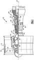
- FIG. 1 schematically illustrates a gas turbine engine 20.
- the gas turbine engine 20 is disclosed herein as a two-spool turbofan that generally incorporates a fan section 22, a compressor section 24, a combustor section 26 and a turbine section 28.
- the fan section 22 drives air along a bypass flow path B in a bypass duct defined within a housing 15, such as a fan case or nacelle, and also drives air along a core flow path C for compression and communication into the combustor section 26 then expansion through the turbine section 28.
- the exemplary engine 20 generally includes a low speed spool 30 and a high speed spool 32 mounted for rotation about an engine central longitudinal axis A relative to an engine static structure 36 via several bearing systems 38. It should be understood that various bearing systems 38 at various locations may alternatively or additionally be provided, and the location of bearing systems 38 may be varied as appropriate to the application.
- the low speed spool 30 generally includes an inner shaft 40 that interconnects, a first (or low) pressure compressor 44 and a first (or low) pressure turbine 46.
- the inner shaft 40 is connected to the fan 42 through a speed change mechanism, which in exemplary gas turbine engine 20 is illustrated as a geared architecture 48 to drive a fan 42 at a lower speed than the low speed spool 30.
- the high speed spool 32 includes an outer shaft 50 that interconnects a second (or high) pressure compressor 52 and a second (or high) pressure turbine 54.
- a combustor 56 is arranged in exemplary gas turbine 20 between the high pressure compressor 52 and the high pressure turbine 54.
- a mid-turbine frame 57 of the engine static structure 36 may be arranged generally between the high pressure turbine 54 and the low pressure turbine 46.
- the mid-turbine frame 57 further supports bearing systems 38 in the turbine section 28.
- the inner shaft 40 and the outer shaft 50 are concentric and rotate via bearing systems 38 about the engine central longitudinal axis A which is colline
- the core airflow is compressed by the low pressure compressor 44 then the high pressure compressor 52, mixed and burned with fuel in the combustor 56, then expanded over the high pressure turbine 54 and low pressure turbine 46.
- the mid-turbine frame 57 includes airfoils 59 which are in the core airflow path C.
- the turbines 46, 54 rotationally drive the respective low speed spool 30 and high speed spool 32 in response to the expansion.
- gear system 48 may be located aft of the low pressure compressor, or aft of the combustor section 26 or even aft of turbine section 28, and fan 42 may be positioned forward or aft of the location of gear system 48.
- the engine 20 in one example is a high-bypass geared aircraft engine.
- the engine 20 bypass ratio is greater than about six (6), with an example embodiment being greater than about ten (10)
- the geared architecture 48 is an epicyclic gear train, such as a planetary gear system or other gear system, with a gear reduction ratio of greater than about 2.3
- the low pressure turbine 46 has a pressure ratio that is greater than about five.
- the engine 20 bypass ratio is greater than about ten (10:1)
- the fan diameter is significantly larger than that of the low pressure compressor 44
- the low pressure turbine 46 has a pressure ratio that is greater than about five 5:1.
- Low pressure turbine 46 pressure ratio is pressure measured prior to inlet of low pressure turbine 46 as related to the pressure at the outlet of the low pressure turbine 46 prior to an exhaust nozzle.
- the geared architecture 48 may be an epicycle gear train, such as a planetary gear system or other gear system, with a gear reduction ratio of greater than about 2.3:1 and less than about 5:1. It should be understood, however, that the above parameters are only exemplary of one embodiment of a geared architecture engine and that the present disclosure is applicable to other gas turbine engines including direct drive turbofans.
- the fan section 22 of the engine 20 is designed for a particular flight conditiontypically cruise at about 0.8 Mach and about 35,000 feet (10,668 meters).
- the flight condition of 0.8 Mach and 35,000 ft (10,668 meters), with the engine at its best fuel consumption - also known as "bucket cruise Thrust Specific Fuel Consumption ('TSFC')" - is the industry standard parameter of lbm of fuel being burned divided by lbf of thrust the engine produces at that minimum point.
- "Low fan pressure ratio” is the pressure ratio across the fan blade alone, without a Fan Exit Guide Vane (“FEGV”) system.
- the low fan pressure ratio as disclosed herein according to one non-limiting embodiment is less than about 1.45.
- the "Low corrected fan tip speed” as disclosed herein according to one non-limiting embodiment is less than about 1150 ft / second (350.5 meters/second).
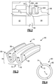
- Figure 2 illustrates an example seal 60, such as a "W"-shape seal, in contact with a first counterface 63A located upstream of the seal 60 and a second counterface 63B located downstream of the seal 60.
- the seal 60 is located in the high pressure turbine 54.
- the seal 60 could be located in other parts of the gas turbine engine 20 such as the compressor section 24, the combustor section 26, or other areas of the turbine section 28.
- An upstream portion of the seal 60 engages the first counterface 63A on a blade outer air seal 61, such as a ceramic blade outer air seal, adjacent a turbine blade 62.
- a downstream portion of the seal 60 engages the second counterface 63B on a structure 64A, such as a vane hook, on a vane, such as an exit guide vane 64.
- the seal 60 creates a separation or barrier between a hot fluid area 66 and a cold fluid area 68. Wear typically occurs in a wear area 70 that includes the seal friction surface on the seal 60.
- the seal 60 is configured to operate in the gas turbine engine 20 at temperatures in excess of 700°C and in another example, the seal 60 is configured to operate in the gas turbine engine 20 at temperatures in excess of 900°C.
- the seal 60 has an inner diameter 72, an outer diameter 74, a radial height 76, and a width 78 in an axial direction.
- the seal 60 includes a body portion 84 extending between a leading edge 80 and a trailing edge 82.
- the seal 60 further includes a plurality of bends 86 disposed between the leading edge 80 and the trailing edge 82.
- the plurality of bends 86 can be any one of a trough, ridge, or other geometric profile.
- the seal 60 includes two bends adjacent the inner diameter 72 and a single bend adjacent the outer diameter 74.
- other bend configurations could include at least one bend adjacent either the leading edge 80 or the trailing edge 82 or both the leading and trailing edges 80, 82.
- the body portion 84 defines a complete ring without any separations or discontinuities in the circumferential or axial directions. Alternatively, the body portion 84 may include a separation or discontinuity and not form a complete ring.
- radial or radially, axial or axially, and circumferential or circumferentially is in relation to the engine axis A unless stated otherwise. Additionally, upstream and downstream is in relation to a general direction of air flow through a core of the gas turbine engine 20 unless stated otherwise.
- the cross-sectional shape is a two-dimensional shape represented by a cross-section of the seal 60 with the cross-sectional shape being substantially the same at a plurality of circumferential locations around the seal 60. While the seal 60 is illustrated with a cross-sectional shape in the form of a "W,” the seal 60 can be of any shape for the application in which it is used such that the seal's shape is application-specific.
- the cross-sectional shape of the seal can be an "O"-shape, a "C”-shape, an "E”-shape, a "M”-shape, a "U”-shape, a Diamond-shape, a Dogbone-shape, a Feather-shape, a Bathtub-seal shape, a Wire-seal shape, or any other geometric shape.
- Figures 5 and 6 illustrate another example seal, such as a piston seal 160.
- the piston seal 160 is similar in composition and manufacturing as the seal 60 except where described below or shown in the Figures.
- the piston seal 160 is disposed in a mid-turbine frame vane 101 aft outside diameter seal groove 100 and against a portion of the engine static structure 36.
- wear typically occurs in a wear area 170 that includes the seal friction surface on the seal 160 and a corresponding counterface on the mid-turbine frame vane 101 with the mid-turbine frame vane 101 being formed from a nickel-based alloy, such as Mar-M247.
- the seal 160 has an inner diameter 172, an outer diameter 174, a radial height 176, and a width 178 in an axial direction. In the illustrated example, the height 176 is greater than the width 178, such that the seal 160 includes a rectangular cross section.
- the seal 160 includes a body portion 184 extending from a leading edge 180 to a trailing edge 182. The body portion 184 follows a constant cross-sectional shape and forms a complete ring without any separations or discontinuities in a circumferential or axial direction. Alternatively, the seal 160 could include a separation or discontinuity.
- the seals 60, 160 are formed from high entropy alloys ("HEA"), such as MoNbTaW, AlCoCrFeNiTi, or CoCrFeMnNi.
- HAA high entropy alloys
- Conventional alloys used in gas turbine engines 20 include one or possibly two main elements with the addition of several other elements in relatively small amounts.
- HEAs are formed from multiple principal elements in high concentrations and can be compositionally tailored to include self-lubrication and wear resistant properties at elevated temperatures.
- Table 1 below illustrates an example composition for CoCrFeMnNi. A similar composition range can also be used for the MoNbTaW and AlCoCrFeNiTi. Table 1: Element Co Cr Fe Mn Ni Ti Al C O CoCrFeMnNi 17.04 15.43 16.97 15.68 17.82 15 0.9 1.02 0.13
- the seals 60, 160 are made through an additive manufacturing process from the HEA. Unlike conventional alloys, HEA are not typically formed directly from casting or ingot + wrought processes.
- the seals 60, 160 are formed through a powder bed system with a computer controlled heat source, such as with a selective laser melting process or an electron beam melting process. With the powdered bed system, the heat source is applied to the powdered HEA forming a layer in a powdered bed to weld or melt the powdered HEA. Additional layers of powdered HEAs can be added after welding or melting existing layers to form the final shape of the seal 60, 160.
- the seals 60,160 could be formed through a powder feed system with a computer controlled heat source, such as with a laser direct deposition process or a laser engineered net shaping ("LENS") process.
- the LENS process uses computer-controlled lasers to weld air-blown streams of powdered HEAs into the desired shape for the seals 60, 160.
- One feature of the LENS process is the ability to generate a seal with sufficient precision in a complex geometry without additional machining steps to achieve a finished seal.
- the LENS process allows for the formation of complex geometries of the seals 60, 160 with a large enough scale to form a circumferential ring on a radially outer side of the core air flow path C in the gas turbine engine 20.
- This is an improvement over prior art designs, such as seals formed from a polycrystalline or single crystal nickel alloy, which are difficult to form in a complex shape with a diameter large enough to surround a core air flow path C in the gas turbine engine 20 and/or withstand elevated operating temperatures of the gas turbine engine 20.
- seals formed directly from cast feedstock may include a joining-related discontinuity formed between opposite ends of the seal 60 which creates a possible leakage path through the seal 60 and can cause an increased amount of hot gases from the core air flow path C mixing with the cold fluid area 68 or another cold fluid area in the gas turbine engine 20.
- seal 60 formed from HEAs such as MoNbTaW
- HEAs such as MoNbTaW
- the seal 60, 160 is in contact with a counterface at elevated temperatures and exhibits a fretting motion with low wear and low friction.
- the low wear and low friction between the seal 60 and the counterface is at least partially attributed to the formation of a metal oxide that forms the solid lubricant.
- the metal oxide can also transfer to the counterface and further reduce friction and heating associated with the frictional forces during operation of the gas turbine engine 20.
- a low friction coefficient and high wear resistance of the seal 60 can also be obtained at low temperatures, such as during engine load fluctuations, and is at least partially attributed to the formation of a Ta-based tribofilm in the case of using MoNbTaW.
- other tribofilms can formed when using other HEAs.
- the above example is with respect to a specific HEA material, other HEA materials exhibit similar properties during both high and low temperature operations.
- seals 60, 160 made from HEAs is an increased time interval between overhauls of the gas turbine engine 20 and a reduction in the number of parts needed to be replaced during an overhaul because of the improved sealing and wear characteristics of the seals 60, 160. Additionally, the low frictional performance of the seals 60, 160 results in less wear on the counterface of the components which extends the life of the component and reduces the number of parts replaced during an overhaul.
- Figure 7 illustrates a method 200 of creating the seals 60, 160.
- the method includes providing (202) a powdered HEA, such as MoNbTaW, AlCoCrFeNiTi, or CoCrFeMnNi.
- the powdered HEA is formed (204) into the shape of the seal 60, 160 through exposure to a heat source, such as a laser beam or an electron beam as described above.
- a heat source such as a laser beam or an electron beam as described above.
- the powdered HEA is air blown while a computer controller laser welds the stream of powdered HEA into the desired shape of the seal 60, 160.
- the precision of the computer-controlled laser is sufficiently precise to allow the seals 60, 160 to be formed without the need for additional machining of an exterior surface of the seal 60, 160, which reduces the number of steps to create the seal 60, 160.
Landscapes
- Engineering & Computer Science (AREA)
- Mechanical Engineering (AREA)
- General Engineering & Computer Science (AREA)
- Chemical & Material Sciences (AREA)
- Manufacturing & Machinery (AREA)
- Materials Engineering (AREA)
- Plasma & Fusion (AREA)
- Physics & Mathematics (AREA)
- Ceramic Engineering (AREA)
- Civil Engineering (AREA)
- Composite Materials (AREA)
- Structural Engineering (AREA)
- Metallurgy (AREA)
- Organic Chemistry (AREA)
- Turbine Rotor Nozzle Sealing (AREA)
Abstract
Description
- This disclosure relates to seals and the materials and methods for making the seals. Seals are widely used in various applications to contain a fluid in a desired area of a piece of equipment. Many different types of materials can be used to fabricate seals according to many different types of design. For example, stationary seals are attached to a fixed component and create a seal with another fixed component or a moving component. Alternatively, a seal may move with one component to create a seal with another component hat is fixed or moves. Both moving and stationary seals seals can be subject to wear and other undesirable effects from friction between the seal and a contact surface on a component.
- Systems that operate in extreme environments, such as the high temperatures and pressures experienced inside a gas turbine engine, must be able to withstand these environments while still exhibiting favorable wear characteristics. Historically, seals in gas turbine engines have been made from various materials, such as INCONEL® 718, INCONEL X-750, or other nickel-based alloys. However, as operating temperatures within the gas turbine engine increase, there is a need for seals that can withstand these environments.
- In one exemplary embodiment, a tribological and creep resistant system configured to operate at temperatures in excess of 700°C. includes a seal body that extends between a leading edge and a trailing edge. A first component contact surface is adjacent the leading edge and a second component contact surface is adjacent the trailing edge. The seal body is formed from a high entropy alloy.
- In a further embodiment of any of the above, the seal body forms a complete ring.
- In a further embodiment of any of the above, the system is configured to operate at temperatures up to 900°C.
- In a further embodiment of any of the above, a gas turbine engine with the seal body is located radially outward of a core airflow path through the gas turbine engine in a turbine section of the gas turbine engine.
- In a further embodiment of any of the above, a gas turbine engine with the seal body is located radially outward of a core airflow path through the gas turbine engine in a high pressure compressor of the gas turbine engine.
- In a further embodiment of any of the above, the seal body includes at least one bend.
- In a further embodiment of any of the above, the at least one bend includes multiple bends on one of a radially inner side or a radially outer side of the seal body. Only a single bend is on the other of the radially inner side or the radially outer side.
- In a further embodiment of any of the above, a first component engages the first component contact surface on the leading edge of the body seal. A second component engages the second component contact surface on the trialing edge of the body seal.
- In a further embodiment of any of the above, the first component is a vane and the second component is a blade outer air seal.
- In a further embodiment of any of the above, a first component defines a groove that seats a radially inner portion of the seal body. The seal body defines a piston seal.
- In a further embodiment of any of the above, the first component is a mid-turbine frame vane and the groove is located on a radially outer portion of the mid-turbine frame vane.
- In a further embodiment of any of the above, the high entropy alloy includes one of MoNbTaW, AlCoCrFeNiTi, or CoCrFeMnNi.
- In another exemplary embodiment, a method includes providing a powdered high entropy alloy. The powdered high entropy alloy is formed into a seal body with a heat source. The seal body extends between a leading edge and a trailing edge. A first component contact surface is adjacent the leading edge and a second component contact surface is adjacent the trailing edge and is configured to operate at temperatures in excess of 700°C.
- In a further embodiment of any of the above, the powdered high entropy alloy utilizes a powdered bed of the high entropy alloy. Forming the powdered high entropy alloy into the seal body with the heat source includes welding or melting adjacent layers of the high entropy alloy in the powdered bed to form a desired shape of the seal body.
- In a further embodiment of any of the above, providing the powdered high entropy alloy includes blowing streams of the powdered high entropy alloy.
- In a further embodiment of any of the above, forming the powdered high entropy alloy into a seal body with the heat source includes controlling the heat source to weld or melt the high entropy alloy into a desired shape of the seal body.
- In a further embodiment of any of the above, the seal body extends from a leading edge to a trailing edge and includes at least one bend.
- In a further embodiment of any of the above, the seal body extends from a leading edge to a trailing edge and defines a piston seal.
- In a further embodiment of any of the above, the seal body forms a complete ring of sufficient diameter to surround a core air flow path in a gas turbine engine.
- In a further embodiment of any of the above, the powdered high entropy alloy includes one of MoNbTaW, AlCoCrFeNiTi, or CoCrFeMnNi.
- The various features and advantages of the present disclosure will become apparent to those skilled in the art from the following detailed description. The drawings that accompany the detailed description can be briefly described as follows.
-
Figure 1 is a schematic view of an example gas turbine engine. -
Figure 2 is a schematic view of an example seal located in the gas turbine engine ofFigure 1 . -
Figure 3 is a partial perspective view of the seal ofFigure 2 illustrating a cross section of the seal. -
Figure 4 is an axial view of the seal ofFigure 2 . -
Figure 5 is a schematic view of an example piston seal located in the gas turbine engine ofFigure 1 . -
Figure 6 illustrates an axial view of the piston seal ofFigure 5 -
Figure 7 illustrates a method of creating a seal from a high entropy alloy. -
Figure 1 schematically illustrates agas turbine engine 20. Thegas turbine engine 20 is disclosed herein as a two-spool turbofan that generally incorporates afan section 22, acompressor section 24, acombustor section 26 and aturbine section 28. Thefan section 22 drives air along a bypass flow path B in a bypass duct defined within ahousing 15, such as a fan case or nacelle, and also drives air along a core flow path C for compression and communication into thecombustor section 26 then expansion through theturbine section 28. Although depicted as a two-spool turbofan gas turbine engine in the disclosed non-limiting embodiment, it should be understood that the concepts described herein are not limited to use with two-spool turbofans as the teachings may be applied to other types of turbine engines including three-spool architectures. - The
exemplary engine 20 generally includes alow speed spool 30 and ahigh speed spool 32 mounted for rotation about an engine central longitudinal axis A relative to an enginestatic structure 36 viaseveral bearing systems 38. It should be understood thatvarious bearing systems 38 at various locations may alternatively or additionally be provided, and the location ofbearing systems 38 may be varied as appropriate to the application. - The
low speed spool 30 generally includes aninner shaft 40 that interconnects, a first (or low) pressure compressor 44 and a first (or low)pressure turbine 46. Theinner shaft 40 is connected to thefan 42 through a speed change mechanism, which in exemplarygas turbine engine 20 is illustrated as a gearedarchitecture 48 to drive afan 42 at a lower speed than thelow speed spool 30. Thehigh speed spool 32 includes anouter shaft 50 that interconnects a second (or high)pressure compressor 52 and a second (or high)pressure turbine 54. Acombustor 56 is arranged inexemplary gas turbine 20 between thehigh pressure compressor 52 and thehigh pressure turbine 54. Amid-turbine frame 57 of the enginestatic structure 36 may be arranged generally between thehigh pressure turbine 54 and thelow pressure turbine 46. Themid-turbine frame 57 further supports bearingsystems 38 in theturbine section 28. Theinner shaft 40 and theouter shaft 50 are concentric and rotate viabearing systems 38 about the engine central longitudinal axis A which is collinear with their longitudinal axes. - The core airflow is compressed by the low pressure compressor 44 then the
high pressure compressor 52, mixed and burned with fuel in thecombustor 56, then expanded over thehigh pressure turbine 54 andlow pressure turbine 46. Themid-turbine frame 57 includesairfoils 59 which are in the core airflow path C. Theturbines low speed spool 30 andhigh speed spool 32 in response to the expansion. It will be appreciated that each of the positions of thefan section 22,compressor section 24,combustor section 26,turbine section 28, and fandrive gear system 48 may be varied. For example,gear system 48 may be located aft of the low pressure compressor, or aft of thecombustor section 26 or even aft ofturbine section 28, andfan 42 may be positioned forward or aft of the location ofgear system 48. - The
engine 20 in one example is a high-bypass geared aircraft engine. In a further example, theengine 20 bypass ratio is greater than about six (6), with an example embodiment being greater than about ten (10), the gearedarchitecture 48 is an epicyclic gear train, such as a planetary gear system or other gear system, with a gear reduction ratio of greater than about 2.3 and thelow pressure turbine 46 has a pressure ratio that is greater than about five. In one disclosed embodiment, theengine 20 bypass ratio is greater than about ten (10:1), the fan diameter is significantly larger than that of the low pressure compressor 44, and thelow pressure turbine 46 has a pressure ratio that is greater than about five 5:1.Low pressure turbine 46 pressure ratio is pressure measured prior to inlet oflow pressure turbine 46 as related to the pressure at the outlet of thelow pressure turbine 46 prior to an exhaust nozzle. The gearedarchitecture 48 may be an epicycle gear train, such as a planetary gear system or other gear system, with a gear reduction ratio of greater than about 2.3:1 and less than about 5:1. It should be understood, however, that the above parameters are only exemplary of one embodiment of a geared architecture engine and that the present disclosure is applicable to other gas turbine engines including direct drive turbofans. - A significant amount of thrust is provided by the bypass flow B due to the high bypass ratio. The
fan section 22 of theengine 20 is designed for a particular flight conditiontypically cruise at about 0.8 Mach and about 35,000 feet (10,668 meters). The flight condition of 0.8 Mach and 35,000 ft (10,668 meters), with the engine at its best fuel consumption - also known as "bucket cruise Thrust Specific Fuel Consumption ('TSFC')" - is the industry standard parameter of lbm of fuel being burned divided by lbf of thrust the engine produces at that minimum point. "Low fan pressure ratio" is the pressure ratio across the fan blade alone, without a Fan Exit Guide Vane ("FEGV") system. The low fan pressure ratio as disclosed herein according to one non-limiting embodiment is less than about 1.45. "Low corrected fan tip speed" is the actual fan tip speed in ft/sec divided by an industry standard temperature correction of [(Tram °R) / (518.7 °R)]0.5 (where °R = K x 9/5). The "Low corrected fan tip speed" as disclosed herein according to one non-limiting embodiment is less than about 1150 ft / second (350.5 meters/second). -
Figure 2 illustrates anexample seal 60, such as a "W"-shape seal, in contact with afirst counterface 63A located upstream of theseal 60 and asecond counterface 63B located downstream of theseal 60. In the illustrated example, theseal 60 is located in thehigh pressure turbine 54. However, theseal 60 could be located in other parts of thegas turbine engine 20 such as thecompressor section 24, thecombustor section 26, or other areas of theturbine section 28. An upstream portion of theseal 60 engages thefirst counterface 63A on a bladeouter air seal 61, such as a ceramic blade outer air seal, adjacent aturbine blade 62. A downstream portion of theseal 60 engages thesecond counterface 63B on astructure 64A, such as a vane hook, on a vane, such as anexit guide vane 64. Theseal 60 creates a separation or barrier between ahot fluid area 66 and acold fluid area 68. Wear typically occurs in awear area 70 that includes the seal friction surface on theseal 60. In one example, theseal 60 is configured to operate in thegas turbine engine 20 at temperatures in excess of 700°C and in another example, theseal 60 is configured to operate in thegas turbine engine 20 at temperatures in excess of 900°C. - As shown in
Figures 2-4 , theseal 60 has aninner diameter 72, anouter diameter 74, aradial height 76, and awidth 78 in an axial direction. Theseal 60 includes abody portion 84 extending between aleading edge 80 and a trailingedge 82. Theseal 60 further includes a plurality ofbends 86 disposed between theleading edge 80 and the trailingedge 82. The plurality ofbends 86 can be any one of a trough, ridge, or other geometric profile. In the illustrated example, theseal 60 includes two bends adjacent theinner diameter 72 and a single bend adjacent theouter diameter 74. However, other bend configurations could include at least one bend adjacent either theleading edge 80 or the trailingedge 82 or both the leading and trailingedges - The
body portion 84 defines a complete ring without any separations or discontinuities in the circumferential or axial directions. Alternatively, thebody portion 84 may include a separation or discontinuity and not form a complete ring. In this disclosure, radial or radially, axial or axially, and circumferential or circumferentially is in relation to the engine axis A unless stated otherwise. Additionally, upstream and downstream is in relation to a general direction of air flow through a core of thegas turbine engine 20 unless stated otherwise. - In the illustrated example, the cross-sectional shape is a two-dimensional shape represented by a cross-section of the
seal 60 with the cross-sectional shape being substantially the same at a plurality of circumferential locations around theseal 60. While theseal 60 is illustrated with a cross-sectional shape in the form of a "W," theseal 60 can be of any shape for the application in which it is used such that the seal's shape is application-specific. In other embodiments, the cross-sectional shape of the seal can be an "O"-shape, a "C"-shape, an "E"-shape, a "M"-shape, a "U"-shape, a Diamond-shape, a Dogbone-shape, a Feather-shape, a Bathtub-seal shape, a Wire-seal shape, or any other geometric shape. -
Figures 5 and 6 illustrate another example seal, such as apiston seal 160. Thepiston seal 160 is similar in composition and manufacturing as theseal 60 except where described below or shown in the Figures. In the illustrated example, thepiston seal 160 is disposed in amid-turbine frame vane 101 aft outsidediameter seal groove 100 and against a portion of the enginestatic structure 36. In this example embodiment, wear typically occurs in awear area 170 that includes the seal friction surface on theseal 160 and a corresponding counterface on themid-turbine frame vane 101 with themid-turbine frame vane 101 being formed from a nickel-based alloy, such as Mar-M247. - The
seal 160 has aninner diameter 172, anouter diameter 174, aradial height 176, and awidth 178 in an axial direction. In the illustrated example, theheight 176 is greater than thewidth 178, such that theseal 160 includes a rectangular cross section. Theseal 160 includes a body portion 184 extending from aleading edge 180 to a trailingedge 182. The body portion 184 follows a constant cross-sectional shape and forms a complete ring without any separations or discontinuities in a circumferential or axial direction. Alternatively, theseal 160 could include a separation or discontinuity. - The
seals gas turbine engines 20 include one or possibly two main elements with the addition of several other elements in relatively small amounts. Conversely, HEAs are formed from multiple principal elements in high concentrations and can be compositionally tailored to include self-lubrication and wear resistant properties at elevated temperatures. - Table 1 below illustrates an example composition for CoCrFeMnNi. A similar composition range can also be used for the MoNbTaW and AlCoCrFeNiTi.
Table 1: Element Co Cr Fe Mn Ni Ti Al C O CoCrFeMnNi 17.04 15.43 16.97 15.68 17.82 15 0.9 1.02 0.13 - In one example, the
seals seals seal - In another example, the seals 60,160 could be formed through a powder feed system with a computer controlled heat source, such as with a laser direct deposition process or a laser engineered net shaping ("LENS") process. The LENS process uses computer-controlled lasers to weld air-blown streams of powdered HEAs into the desired shape for the
seals - The LENS process, as well as the other HEA forming processes discussed above, allow for the formation of complex geometries of the
seals gas turbine engine 20. This is an improvement over prior art designs, such as seals formed from a polycrystalline or single crystal nickel alloy, which are difficult to form in a complex shape with a diameter large enough to surround a core air flow path C in thegas turbine engine 20 and/or withstand elevated operating temperatures of thegas turbine engine 20. Additionally, seals formed directly from cast feedstock may include a joining-related discontinuity formed between opposite ends of theseal 60 which creates a possible leakage path through theseal 60 and can cause an increased amount of hot gases from the core air flow path C mixing with thecold fluid area 68 or another cold fluid area in thegas turbine engine 20. - Another feature of the
seal 60 formed from HEAs, such as MoNbTaW, is the formation of a solid lubricant between theseal gas turbine engine 20, theseal seal 60 and the counterface is at least partially attributed to the formation of a metal oxide that forms the solid lubricant. The metal oxide can also transfer to the counterface and further reduce friction and heating associated with the frictional forces during operation of thegas turbine engine 20. - Additionally, a low friction coefficient and high wear resistance of the
seal 60 can also be obtained at low temperatures, such as during engine load fluctuations, and is at least partially attributed to the formation of a Ta-based tribofilm in the case of using MoNbTaW. However, other tribofilms can formed when using other HEAs. Although the above example is with respect to a specific HEA material, other HEA materials exhibit similar properties during both high and low temperature operations. - One feature of the
seals gas turbine engine 20 and a reduction in the number of parts needed to be replaced during an overhaul because of the improved sealing and wear characteristics of theseals seals -
Figure 7 illustrates amethod 200 of creating theseals seal seal seals seal seal - Although the different non-limiting examples are illustrated as having specific components, the examples of this disclosure are not limited to those particular combinations. It is possible to use some of the components or features from any of the non-limiting examples in combination with features or components from any of the other non-limiting examples.
- It should be understood that like reference numerals identify corresponding or similar elements throughout the several drawings. It should also be understood that although a particular component arrangement is disclosed and illustrated in these exemplary embodiments, other arrangements could also benefit from the teachings of this disclosure.
- The foregoing description shall be interpreted as illustrative and not in any limiting sense. A worker of ordinary skill in the art would understand that certain modifications could come within the scope of this disclosure. For these reasons, the following claim should be studied to determine the true scope and content of this disclosure.
Claims (15)
- A tribological and creep resistant system configured to operate at temperatures in excess of 700°C., comprising:a seal body (84; 184) extending between a leading edge (80; 180) and a trailing edge (82; 182) including a first component contact surface adjacent the leading edge (80; 180) and a second component contact surface adjacent the trailing edge (82; 182),wherein the seal body (84; 184) is formed from a high entropy alloy.
- The system of claim 1, wherein the seal body (84; 184) forms a complete ring.
- The system of claim 1 or 2, wherein the system is configured to operate at temperatures up to 900°C.
- The system of any of claims 1, 2 or 3, further comprising a gas turbine engine (20) with the seal body (84; 184) located radially outward of a core airflow path (C) through the gas turbine engine (20) in a turbine section (28) of the gas turbine engine (20).
- The system of any of claims 1, 2 or 3, further comprising a gas turbine engine (20) with the seal body located radially outward of a core airflow path (C) through the gas turbine engine (20) in a high pressure compressor (52) of the gas turbine engine (20).
- The system of any preceding claim, wherein the seal body (84) includes at least one bend (86).
- The system of claim 6, wherein the at least one bend (86) includes multiple bends on one of a radially inner side (72) or a radially outer side (74) of the seal body (84) and only a single bend (86) on the other of the radially inner side (72) or the radially outer side (74).
- The system of any preceding claim, further comprising:a first component (61) engaging the first component contact surface on the leading edge (80) of the seal body (84) and a second component (64) engaging the second component contact surface on the trailing edge (82) of the seal body (84), optionally wherein the first component is a blade outer air seal (61) and the second component is a vane (64).
- The system of any of claims 1 to 5, further comprising:a first component (101) defining a groove (100) that seats a radially inner portion (172) of the seal body (184), wherein the seal body (184) defines a piston seal (160), optionally wherein the first component is a mid-turbine frame vane (101) and the groove is located on a radially outer portion of the mid-turbine frame vane (101).
- A method comprising:providing a powdered high entropy alloy; andforming the powdered high entropy alloy into a seal body (84; 184) with a heat source, wherein the seal body (84; 184) extends between a leading edge (80; 180) and a trailing edge (82; 182) and includes a first component contact surface adjacent the leading edge (80; 180) and a second component contact surface adjacent the trailing edge (82; 182) and is configured to operate at temperatures in excess of 700°C.
- The method of claim 10, wherein providing the powdered high entropy alloy includes utilizing a powdered bed of the high entropy alloy and forming the powdered high entropy alloy into the seal body (84; 184) with the heat source includes welding or melting adjacent layers of the high entropy alloy in the powdered bed to form a desired shape of the seal body (84; 184).
- The method of claim 10, wherein providing the powdered high entropy alloy includes blowing streams of the powdered high entropy alloy, optionally wherein forming the powdered high entropy alloy into a seal body (84; 184) with the heat source includes controlling the heat source to weld or melt the high entropy alloy into a desired shape of the seal body (84; 184).
- The method of any of claims 10 to 12, wherein the seal body (84; 184) extends from a leading edge (80; 180) to a trailing edge (82; 182) and:includes at least one bend (86); ordefines a piston seal (160).
- The method of any of claims 10 to 13, wherein the seal body (84; 184) forms a complete ring of sufficient diameter to surround a core air flow path (C) in a gas turbine engine (20).
- The system or method of any preceding claim, wherein the powdered high entropy alloy includes one of MoNbTaW, AlCoCrFeNiTi, or CoCrFeMnNi.
Applications Claiming Priority (1)
| Application Number | Priority Date | Filing Date | Title |
|---|---|---|---|
| US17/009,907 US11643939B2 (en) | 2020-09-02 | 2020-09-02 | Seals and methods of making seals |
Publications (2)
| Publication Number | Publication Date |
|---|---|
| EP3964694A1 true EP3964694A1 (en) | 2022-03-09 |
| EP3964694B1 EP3964694B1 (en) | 2024-10-30 |
Family
ID=77627066
Family Applications (1)
| Application Number | Title | Priority Date | Filing Date |
|---|---|---|---|
| EP21194652.0A Active EP3964694B1 (en) | 2020-09-02 | 2021-09-02 | Seals and methods of making seals |
Country Status (2)
| Country | Link |
|---|---|
| US (2) | US11643939B2 (en) |
| EP (1) | EP3964694B1 (en) |
Families Citing this family (21)
| Publication number | Priority date | Publication date | Assignee | Title |
|---|---|---|---|---|
| CN115652170B (en) * | 2022-11-11 | 2023-07-25 | 中国科学院兰州化学物理研究所 | A Solid Lubricating Composite Material with Nearly Equal Volume Fraction High Entropy Coupled Phases |
| CA3233598A1 (en) | 2023-03-29 | 2025-10-30 | Concordia University | Multicomponent coating |
| CA3240752A1 (en) | 2023-06-09 | 2025-06-10 | Pratt & Whitney Canada Corp. | Cocr alloy carbide composite coatings for high-temperature applications |
| CA3240756A1 (en) * | 2023-06-09 | 2025-07-02 | Pratt & Whitney Canada Corp. | Manufacturing of wear resistant coatings |
| EP4474519A1 (en) | 2023-06-09 | 2024-12-11 | Pratt & Whitney Canada Corp. | High entropy alloy repair of nickel and cobalt superalloys |
| US12158072B1 (en) | 2023-12-04 | 2024-12-03 | Rolls-Royce Corporation | Turbine shroud segments with damping strip seals |
| US12241376B1 (en) | 2023-12-04 | 2025-03-04 | Rolls-Royce Corporation | Locating plate for use with turbine shroud assemblies |
| US12286906B1 (en) | 2023-12-04 | 2025-04-29 | Rolls-Royce Corporation | Locating plate for use with turbine shroud assemblies |
| US12188365B1 (en) | 2023-12-04 | 2025-01-07 | Rolls-Royce Corporation | Method and apparatus for ceramic matrix composite turbine shroud assembly |
| US12286885B1 (en) | 2023-12-04 | 2025-04-29 | Rolls-Royce Corporation | Turbine assembly with confronting vane and turbine shroud segment |
| US12421862B2 (en) | 2023-12-04 | 2025-09-23 | Rolls-Royce Corporation | Turbine shroud assembly with angled cooling holes |
| US12152499B1 (en) | 2023-12-04 | 2024-11-26 | Rolls-Royce Corporation | Turbine shroud segments with strip seal assemblies having dampened ends |
| US12421870B1 (en) | 2024-04-30 | 2025-09-23 | Rolls-Royce Corporation | Pin mounted ceramic matrix composite heat shields with impingement cooling |
| US12305525B1 (en) | 2024-05-30 | 2025-05-20 | Rolls-Royce Corporation | Turbine shroud assemblies with rod seal and strip seals |
| US12258880B1 (en) | 2024-05-30 | 2025-03-25 | Rolls-Royce Corporation | Turbine shroud assemblies with inter-segment strip seal |
| US12416241B1 (en) | 2024-05-30 | 2025-09-16 | Rolls-Royce Corporation | Turbine shroud assemblies with strip seals |
| US12215593B1 (en) | 2024-05-30 | 2025-02-04 | Rolls-Royce Corporation | Turbine shroud assembly with inter-segment damping |
| US12410725B1 (en) | 2024-05-31 | 2025-09-09 | Rolls-Royce Corporation | Turbine shroud assemblies with air activated pistons for biasing buffer cavity seals |
| US12352176B1 (en) | 2024-05-31 | 2025-07-08 | Rolls-Royce Corporation | Turbine shroud assemblies with channels for buffer cavity seal thermal management |
| US12577881B2 (en) | 2024-05-31 | 2026-03-17 | Rolls-Royce Corporation | Turbine shroud assemblies with anti-migration seals |
| US12228044B1 (en) | 2024-06-26 | 2025-02-18 | Rolls-Royce Corporation | Turbine shroud system with ceramic matrix composite segments and dual inter-segment seals |
Citations (4)
| Publication number | Priority date | Publication date | Assignee | Title |
|---|---|---|---|---|
| WO2019088157A1 (en) * | 2017-10-31 | 2019-05-09 | 日立金属株式会社 | Alloy material, product using said alloy material, and fluid machine having said product |
| US20190226058A1 (en) * | 2017-08-09 | 2019-07-25 | Hitachi Metals, Ltd. | Alloy member, process for producing said alloy member, and product including said alloy member |
| CN110938770A (en) * | 2019-12-26 | 2020-03-31 | 中国科学院兰州化学物理研究所 | Dynamic sealing material and preparation method and application thereof |
| US20200261980A1 (en) * | 2019-02-20 | 2020-08-20 | Hamilton Sundstrand Corporation | Method for identifying and forming viable high entropy alloys via additive manufacturing |
Family Cites Families (19)
| Publication number | Priority date | Publication date | Assignee | Title |
|---|---|---|---|---|
| WO2015002673A2 (en) * | 2013-02-20 | 2015-01-08 | United Technologies Corporation | Gas turbine engine seal assembly |
| FR3014339B1 (en) * | 2013-12-06 | 2016-01-08 | Snecma | PROCESS FOR MANUFACTURING A PIECE BY SELECTIVE FUSION OF POWDER |
| EP3105421A4 (en) | 2014-01-23 | 2017-12-27 | United Technologies Corporation | Conformal air seal with low friction maxmet layer |
| US10895015B1 (en) * | 2014-12-16 | 2021-01-19 | Hrl Laboratories, Llc | Thin-walled high temperature alloy structures via multi-material additive manufacturing |
| US10830357B2 (en) | 2015-04-24 | 2020-11-10 | Raytheon Technologies Corporation | Single crystal grain structure seals and method of forming |
| US11428321B2 (en) | 2015-05-01 | 2022-08-30 | Saint-Gobain Performance Plastics Corporation | Seals |
| CN105478724B (en) * | 2015-12-23 | 2017-08-29 | 华南理工大学 | A kind of high-entropy alloy particle enhanced aluminum-based composite material and its stirring casting preparation technology |
| EP3408047B8 (en) | 2016-01-27 | 2022-08-17 | H.C. Starck Inc. | Fabrication of high-entropy alloy wire and multi-principal element alloy wire for additive manufacturing |
| US10202863B2 (en) * | 2016-05-23 | 2019-02-12 | United Technologies Corporation | Seal ring for gas turbine engines |
| US20190010702A1 (en) | 2017-07-05 | 2019-01-10 | Robert Lloyd | Metal laminate base sheet for use with masonry structure |
| US11208907B2 (en) * | 2017-07-13 | 2021-12-28 | Raytheon Technologies Corporation | Seals and methods of making seals |
| US20190255608A1 (en) * | 2018-02-21 | 2019-08-22 | Honeywell International Inc. | Methods for additively manufacturing turbine engine components via binder jet printing with titanium aluminide alloys |
| JP7436461B2 (en) * | 2018-10-09 | 2024-02-21 | エリコン メテコ(ユーエス)インコーポレイテッド | High entropy oxide for thermal barrier coating (TBC) top coat |
| CN110117788A (en) * | 2019-05-26 | 2019-08-13 | 天津大学 | A kind of preparation method of CoCrFeMnNi high-entropy alloy cladding layer |
| US11180996B2 (en) * | 2019-10-23 | 2021-11-23 | GM Global Technology Operations LLC | Thermal barrier coated vehicle turbocharger turbine wheel |
| CN110860784B (en) * | 2019-12-02 | 2021-04-13 | 东北大学秦皇岛分校 | Friction stir welding method for preparing bulk high-entropy alloy |
| CN111334697B (en) * | 2020-03-10 | 2021-07-09 | 中国人民解放军军事科学院国防科技创新研究院 | A kind of W-Ta-Mo-Nb-C high-temperature high-entropy alloy and preparation method thereof |
| CN111809094B (en) * | 2020-06-03 | 2021-12-14 | 上海理工大学 | High-entropy alloy resistant to high-temperature oxidation, thermal barrier coating and preparation method of thermal barrier coating |
| CN114934206B (en) * | 2022-05-27 | 2023-03-21 | 广东工业大学 | Multi-element aluminide reinforced aluminum-based composite material and preparation method and application thereof |
-
2020
- 2020-09-02 US US17/009,907 patent/US11643939B2/en active Active
-
2021
- 2021-09-02 EP EP21194652.0A patent/EP3964694B1/en active Active
-
2023
- 2023-02-10 US US18/108,136 patent/US12055043B2/en active Active
Patent Citations (4)
| Publication number | Priority date | Publication date | Assignee | Title |
|---|---|---|---|---|
| US20190226058A1 (en) * | 2017-08-09 | 2019-07-25 | Hitachi Metals, Ltd. | Alloy member, process for producing said alloy member, and product including said alloy member |
| WO2019088157A1 (en) * | 2017-10-31 | 2019-05-09 | 日立金属株式会社 | Alloy material, product using said alloy material, and fluid machine having said product |
| US20200261980A1 (en) * | 2019-02-20 | 2020-08-20 | Hamilton Sundstrand Corporation | Method for identifying and forming viable high entropy alloys via additive manufacturing |
| CN110938770A (en) * | 2019-12-26 | 2020-03-31 | 中国科学院兰州化学物理研究所 | Dynamic sealing material and preparation method and application thereof |
Also Published As
| Publication number | Publication date |
|---|---|
| US20230184124A1 (en) | 2023-06-15 |
| US11643939B2 (en) | 2023-05-09 |
| US12055043B2 (en) | 2024-08-06 |
| US20220065122A1 (en) | 2022-03-03 |
| EP3964694B1 (en) | 2024-10-30 |
Similar Documents
| Publication | Publication Date | Title |
|---|---|---|
| EP3964694B1 (en) | Seals and methods of making seals | |
| US10935139B2 (en) | Dual-ended brush seal assembly and method of manufacture | |
| EP3734021B1 (en) | Blade outer air seal assembly | |
| EP3495699B1 (en) | Conformal seal | |
| EP2875224B1 (en) | Radial position control of case supported structure | |
| US10683768B2 (en) | Circumferential axial segmented trough seal | |
| EP3623704B1 (en) | Combustor panel for gas turbine engine | |
| US20210062667A1 (en) | Seal arrangement for turbine engine component | |
| US12060796B2 (en) | Seals and methods of making seals | |
| US11512604B1 (en) | Spring for radially stacked assemblies | |
| US9752442B2 (en) | Airfoil with variable profile responsive to thermal conditions | |
| EP3620612B1 (en) | Boas intersegment seal | |
| EP3587740A1 (en) | Gas turbine engine component | |
| EP3085901A1 (en) | Seal | |
| WO2014175951A2 (en) | Gas turbine engine component with twisted internal channel | |
| EP3133251B1 (en) | Blade outer air seal component with varying thermal expansion coefficient | |
| EP3722569B1 (en) | Blade outer air seal and turbine section | |
| EP3045666B1 (en) | Airfoil platform with cooling feed orifices | |
| EP3819527B1 (en) | Double angled brush seal for a gas turbine engine | |
| EP4086435B1 (en) | Variable thickness machinable coating for platform seals | |
| EP3486436B1 (en) | Ablatable shaft feature in a gas turbine engine | |
| US10968746B2 (en) | Serpentine turn cover for gas turbine stator vane assembly | |
| EP4105450A1 (en) | Passive clearance control (apcc) system produced by field assisted sintering technology (fast) | |
| EP4056812A1 (en) | Chevron grooved mateface seal |
Legal Events
| Date | Code | Title | Description |
|---|---|---|---|
| PUAI | Public reference made under article 153(3) epc to a published international application that has entered the european phase |
Free format text: ORIGINAL CODE: 0009012 |
|
| STAA | Information on the status of an ep patent application or granted ep patent |
Free format text: STATUS: THE APPLICATION HAS BEEN PUBLISHED |
|
| AK | Designated contracting states |
Kind code of ref document: A1 Designated state(s): AL AT BE BG CH CY CZ DE DK EE ES FI FR GB GR HR HU IE IS IT LI LT LU LV MC MK MT NL NO PL PT RO RS SE SI SK SM TR |
|
| STAA | Information on the status of an ep patent application or granted ep patent |
Free format text: STATUS: REQUEST FOR EXAMINATION WAS MADE |
|
| 17P | Request for examination filed |
Effective date: 20220909 |
|
| RBV | Designated contracting states (corrected) |
Designated state(s): AL AT BE BG CH CY CZ DE DK EE ES FI FR GB GR HR HU IE IS IT LI LT LU LV MC MK MT NL NO PL PT RO RS SE SI SK SM TR |
|
| RAP3 | Party data changed (applicant data changed or rights of an application transferred) |
Owner name: RTX CORPORATION |
|
| GRAP | Despatch of communication of intention to grant a patent |
Free format text: ORIGINAL CODE: EPIDOSNIGR1 |
|
| STAA | Information on the status of an ep patent application or granted ep patent |
Free format text: STATUS: GRANT OF PATENT IS INTENDED |
|
| RIC1 | Information provided on ipc code assigned before grant |
Ipc: B33Y 10/00 20150101ALI20240423BHEP Ipc: B33Y 80/00 20150101ALI20240423BHEP Ipc: B33Y 70/10 20200101ALI20240423BHEP Ipc: B22F 5/00 20060101ALI20240423BHEP Ipc: B22F 10/25 20210101ALI20240423BHEP Ipc: C22C 30/00 20060101ALI20240423BHEP Ipc: B22F 10/28 20210101ALI20240423BHEP Ipc: F01D 11/00 20060101AFI20240423BHEP |
|
| INTG | Intention to grant announced |
Effective date: 20240515 |
|
| GRAS | Grant fee paid |
Free format text: ORIGINAL CODE: EPIDOSNIGR3 |
|
| GRAA | (expected) grant |
Free format text: ORIGINAL CODE: 0009210 |
|
| STAA | Information on the status of an ep patent application or granted ep patent |
Free format text: STATUS: THE PATENT HAS BEEN GRANTED |
|
| AK | Designated contracting states |
Kind code of ref document: B1 Designated state(s): AL AT BE BG CH CY CZ DE DK EE ES FI FR GB GR HR HU IE IS IT LI LT LU LV MC MK MT NL NO PL PT RO RS SE SI SK SM TR |
|
| REG | Reference to a national code |
Ref country code: GB Ref legal event code: FG4D |
|
| REG | Reference to a national code |
Ref country code: CH Ref legal event code: EP |
|
| REG | Reference to a national code |
Ref country code: IE Ref legal event code: FG4D |
|
| REG | Reference to a national code |
Ref country code: DE Ref legal event code: R096 Ref document number: 602021020915 Country of ref document: DE |
|
| REG | Reference to a national code |
Ref country code: LT Ref legal event code: MG9D |
|
| REG | Reference to a national code |
Ref country code: NL Ref legal event code: MP Effective date: 20241030 |
|
| PG25 | Lapsed in a contracting state [announced via postgrant information from national office to epo] |
Ref country code: PT Free format text: LAPSE BECAUSE OF FAILURE TO SUBMIT A TRANSLATION OF THE DESCRIPTION OR TO PAY THE FEE WITHIN THE PRESCRIBED TIME-LIMIT Effective date: 20250228 Ref country code: IS Free format text: LAPSE BECAUSE OF FAILURE TO SUBMIT A TRANSLATION OF THE DESCRIPTION OR TO PAY THE FEE WITHIN THE PRESCRIBED TIME-LIMIT Effective date: 20250228 Ref country code: HR Free format text: LAPSE BECAUSE OF FAILURE TO SUBMIT A TRANSLATION OF THE DESCRIPTION OR TO PAY THE FEE WITHIN THE PRESCRIBED TIME-LIMIT Effective date: 20241030 |
|
| PG25 | Lapsed in a contracting state [announced via postgrant information from national office to epo] |
Ref country code: NL Free format text: LAPSE BECAUSE OF FAILURE TO SUBMIT A TRANSLATION OF THE DESCRIPTION OR TO PAY THE FEE WITHIN THE PRESCRIBED TIME-LIMIT Effective date: 20241030 Ref country code: FI Free format text: LAPSE BECAUSE OF FAILURE TO SUBMIT A TRANSLATION OF THE DESCRIPTION OR TO PAY THE FEE WITHIN THE PRESCRIBED TIME-LIMIT Effective date: 20241030 |
|
| REG | Reference to a national code |
Ref country code: AT Ref legal event code: MK05 Ref document number: 1737049 Country of ref document: AT Kind code of ref document: T Effective date: 20241030 |
|
| PG25 | Lapsed in a contracting state [announced via postgrant information from national office to epo] |
Ref country code: BG Free format text: LAPSE BECAUSE OF FAILURE TO SUBMIT A TRANSLATION OF THE DESCRIPTION OR TO PAY THE FEE WITHIN THE PRESCRIBED TIME-LIMIT Effective date: 20241030 |
|
| PG25 | Lapsed in a contracting state [announced via postgrant information from national office to epo] |
Ref country code: ES Free format text: LAPSE BECAUSE OF FAILURE TO SUBMIT A TRANSLATION OF THE DESCRIPTION OR TO PAY THE FEE WITHIN THE PRESCRIBED TIME-LIMIT Effective date: 20241030 |
|
| PG25 | Lapsed in a contracting state [announced via postgrant information from national office to epo] |
Ref country code: NO Free format text: LAPSE BECAUSE OF FAILURE TO SUBMIT A TRANSLATION OF THE DESCRIPTION OR TO PAY THE FEE WITHIN THE PRESCRIBED TIME-LIMIT Effective date: 20250130 |
|
| PG25 | Lapsed in a contracting state [announced via postgrant information from national office to epo] |
Ref country code: GR Free format text: LAPSE BECAUSE OF FAILURE TO SUBMIT A TRANSLATION OF THE DESCRIPTION OR TO PAY THE FEE WITHIN THE PRESCRIBED TIME-LIMIT Effective date: 20250131 Ref country code: LV Free format text: LAPSE BECAUSE OF FAILURE TO SUBMIT A TRANSLATION OF THE DESCRIPTION OR TO PAY THE FEE WITHIN THE PRESCRIBED TIME-LIMIT Effective date: 20241030 Ref country code: AT Free format text: LAPSE BECAUSE OF FAILURE TO SUBMIT A TRANSLATION OF THE DESCRIPTION OR TO PAY THE FEE WITHIN THE PRESCRIBED TIME-LIMIT Effective date: 20241030 |
|
| PG25 | Lapsed in a contracting state [announced via postgrant information from national office to epo] |
Ref country code: PL Free format text: LAPSE BECAUSE OF FAILURE TO SUBMIT A TRANSLATION OF THE DESCRIPTION OR TO PAY THE FEE WITHIN THE PRESCRIBED TIME-LIMIT Effective date: 20241030 |
|
| PG25 | Lapsed in a contracting state [announced via postgrant information from national office to epo] |
Ref country code: RS Free format text: LAPSE BECAUSE OF FAILURE TO SUBMIT A TRANSLATION OF THE DESCRIPTION OR TO PAY THE FEE WITHIN THE PRESCRIBED TIME-LIMIT Effective date: 20250130 |
|
| PG25 | Lapsed in a contracting state [announced via postgrant information from national office to epo] |
Ref country code: SM Free format text: LAPSE BECAUSE OF FAILURE TO SUBMIT A TRANSLATION OF THE DESCRIPTION OR TO PAY THE FEE WITHIN THE PRESCRIBED TIME-LIMIT Effective date: 20241030 |
|
| PG25 | Lapsed in a contracting state [announced via postgrant information from national office to epo] |
Ref country code: DK Free format text: LAPSE BECAUSE OF FAILURE TO SUBMIT A TRANSLATION OF THE DESCRIPTION OR TO PAY THE FEE WITHIN THE PRESCRIBED TIME-LIMIT Effective date: 20241030 |
|
| PG25 | Lapsed in a contracting state [announced via postgrant information from national office to epo] |
Ref country code: EE Free format text: LAPSE BECAUSE OF FAILURE TO SUBMIT A TRANSLATION OF THE DESCRIPTION OR TO PAY THE FEE WITHIN THE PRESCRIBED TIME-LIMIT Effective date: 20241030 |
|
| PG25 | Lapsed in a contracting state [announced via postgrant information from national office to epo] |
Ref country code: RO Free format text: LAPSE BECAUSE OF FAILURE TO SUBMIT A TRANSLATION OF THE DESCRIPTION OR TO PAY THE FEE WITHIN THE PRESCRIBED TIME-LIMIT Effective date: 20241030 |
|
| PG25 | Lapsed in a contracting state [announced via postgrant information from national office to epo] |
Ref country code: SK Free format text: LAPSE BECAUSE OF FAILURE TO SUBMIT A TRANSLATION OF THE DESCRIPTION OR TO PAY THE FEE WITHIN THE PRESCRIBED TIME-LIMIT Effective date: 20241030 |
|
| PG25 | Lapsed in a contracting state [announced via postgrant information from national office to epo] |
Ref country code: CZ Free format text: LAPSE BECAUSE OF FAILURE TO SUBMIT A TRANSLATION OF THE DESCRIPTION OR TO PAY THE FEE WITHIN THE PRESCRIBED TIME-LIMIT Effective date: 20241030 |
|
| PG25 | Lapsed in a contracting state [announced via postgrant information from national office to epo] |
Ref country code: IT Free format text: LAPSE BECAUSE OF FAILURE TO SUBMIT A TRANSLATION OF THE DESCRIPTION OR TO PAY THE FEE WITHIN THE PRESCRIBED TIME-LIMIT Effective date: 20241030 |
|
| REG | Reference to a national code |
Ref country code: DE Ref legal event code: R097 Ref document number: 602021020915 Country of ref document: DE |
|
| PLBE | No opposition filed within time limit |
Free format text: ORIGINAL CODE: 0009261 |
|
| STAA | Information on the status of an ep patent application or granted ep patent |
Free format text: STATUS: NO OPPOSITION FILED WITHIN TIME LIMIT |
|
| PG25 | Lapsed in a contracting state [announced via postgrant information from national office to epo] |
Ref country code: SE Free format text: LAPSE BECAUSE OF FAILURE TO SUBMIT A TRANSLATION OF THE DESCRIPTION OR TO PAY THE FEE WITHIN THE PRESCRIBED TIME-LIMIT Effective date: 20241030 |
|
| 26N | No opposition filed |
Effective date: 20250731 |
|
| PGFP | Annual fee paid to national office [announced via postgrant information from national office to epo] |
Ref country code: DE Payment date: 20250820 Year of fee payment: 5 |
|
| PGFP | Annual fee paid to national office [announced via postgrant information from national office to epo] |
Ref country code: GB Payment date: 20250820 Year of fee payment: 5 |
|
| PGFP | Annual fee paid to national office [announced via postgrant information from national office to epo] |
Ref country code: FR Payment date: 20250820 Year of fee payment: 5 |