EP3964364A1 - Mobile printer - Google Patents
Mobile printer Download PDFInfo
- Publication number
- EP3964364A1 EP3964364A1 EP21178291.7A EP21178291A EP3964364A1 EP 3964364 A1 EP3964364 A1 EP 3964364A1 EP 21178291 A EP21178291 A EP 21178291A EP 3964364 A1 EP3964364 A1 EP 3964364A1
- Authority
- EP
- European Patent Office
- Prior art keywords
- decolorizing
- casing
- decolorizing device
- temperature
- print head
- Prior art date
- Legal status (The legal status is an assumption and is not a legal conclusion. Google has not performed a legal analysis and makes no representation as to the accuracy of the status listed.)
- Granted
Links
Images



Classifications
-
- B—PERFORMING OPERATIONS; TRANSPORTING
- B41—PRINTING; LINING MACHINES; TYPEWRITERS; STAMPS
- B41J—TYPEWRITERS; SELECTIVE PRINTING MECHANISMS, i.e. MECHANISMS PRINTING OTHERWISE THAN FROM A FORME; CORRECTION OF TYPOGRAPHICAL ERRORS
- B41J2/00—Typewriters or selective printing mechanisms characterised by the printing or marking process for which they are designed
- B41J2/005—Typewriters or selective printing mechanisms characterised by the printing or marking process for which they are designed characterised by bringing liquid or particles selectively into contact with a printing material
- B41J2/01—Ink jet
- B41J2/21—Ink jet for multi-colour printing
-
- B—PERFORMING OPERATIONS; TRANSPORTING
- B41—PRINTING; LINING MACHINES; TYPEWRITERS; STAMPS
- B41J—TYPEWRITERS; SELECTIVE PRINTING MECHANISMS, i.e. MECHANISMS PRINTING OTHERWISE THAN FROM A FORME; CORRECTION OF TYPOGRAPHICAL ERRORS
- B41J2/00—Typewriters or selective printing mechanisms characterised by the printing or marking process for which they are designed
- B41J2/005—Typewriters or selective printing mechanisms characterised by the printing or marking process for which they are designed characterised by bringing liquid or particles selectively into contact with a printing material
- B41J2/01—Ink jet
-
- B—PERFORMING OPERATIONS; TRANSPORTING
- B41—PRINTING; LINING MACHINES; TYPEWRITERS; STAMPS
- B41J—TYPEWRITERS; SELECTIVE PRINTING MECHANISMS, i.e. MECHANISMS PRINTING OTHERWISE THAN FROM A FORME; CORRECTION OF TYPOGRAPHICAL ERRORS
- B41J11/00—Devices or arrangements of selective printing mechanisms, e.g. ink-jet printers or thermal printers, for supporting or handling copy material in sheet or web form
- B41J11/0015—Devices or arrangements of selective printing mechanisms, e.g. ink-jet printers or thermal printers, for supporting or handling copy material in sheet or web form for treating before, during or after printing or for uniform coating or laminating the copy material before or after printing
- B41J11/002—Curing or drying the ink on the copy materials, e.g. by heating or irradiating
-
- B—PERFORMING OPERATIONS; TRANSPORTING
- B41—PRINTING; LINING MACHINES; TYPEWRITERS; STAMPS
- B41J—TYPEWRITERS; SELECTIVE PRINTING MECHANISMS, i.e. MECHANISMS PRINTING OTHERWISE THAN FROM A FORME; CORRECTION OF TYPOGRAPHICAL ERRORS
- B41J11/00—Devices or arrangements of selective printing mechanisms, e.g. ink-jet printers or thermal printers, for supporting or handling copy material in sheet or web form
- B41J11/0015—Devices or arrangements of selective printing mechanisms, e.g. ink-jet printers or thermal printers, for supporting or handling copy material in sheet or web form for treating before, during or after printing or for uniform coating or laminating the copy material before or after printing
- B41J11/002—Curing or drying the ink on the copy materials, e.g. by heating or irradiating
- B41J11/0024—Curing or drying the ink on the copy materials, e.g. by heating or irradiating using conduction means, e.g. by using a heated platen
-
- B—PERFORMING OPERATIONS; TRANSPORTING
- B41—PRINTING; LINING MACHINES; TYPEWRITERS; STAMPS
- B41J—TYPEWRITERS; SELECTIVE PRINTING MECHANISMS, i.e. MECHANISMS PRINTING OTHERWISE THAN FROM A FORME; CORRECTION OF TYPOGRAPHICAL ERRORS
- B41J29/00—Details of, or accessories for, typewriters or selective printing mechanisms not otherwise provided for
- B41J29/38—Drives, motors, controls or automatic cut-off devices for the entire printing mechanism
- B41J29/393—Devices for controlling or analysing the entire machine ; Controlling or analysing mechanical parameters involving printing of test patterns
-
- B—PERFORMING OPERATIONS; TRANSPORTING
- B41—PRINTING; LINING MACHINES; TYPEWRITERS; STAMPS
- B41J—TYPEWRITERS; SELECTIVE PRINTING MECHANISMS, i.e. MECHANISMS PRINTING OTHERWISE THAN FROM A FORME; CORRECTION OF TYPOGRAPHICAL ERRORS
- B41J3/00—Typewriters or selective printing or marking mechanisms characterised by the purpose for which they are constructed
- B41J3/36—Typewriters or selective printing or marking mechanisms characterised by the purpose for which they are constructed for portability, i.e. hand-held printers or laptop printers
-
- B—PERFORMING OPERATIONS; TRANSPORTING
- B43—WRITING OR DRAWING IMPLEMENTS; BUREAU ACCESSORIES
- B43L—ARTICLES FOR WRITING OR DRAWING UPON; WRITING OR DRAWING AIDS; ACCESSORIES FOR WRITING OR DRAWING
- B43L13/00—Drawing instruments, or writing or drawing appliances or accessories not otherwise provided for
- B43L13/02—Draughting machines or drawing devices for keeping parallelism
- B43L13/022—Draughting machines or drawing devices for keeping parallelism automatic
- B43L13/024—Drawing heads therefor
-
- B—PERFORMING OPERATIONS; TRANSPORTING
- B43—WRITING OR DRAWING IMPLEMENTS; BUREAU ACCESSORIES
- B43L—ARTICLES FOR WRITING OR DRAWING UPON; WRITING OR DRAWING AIDS; ACCESSORIES FOR WRITING OR DRAWING
- B43L19/00—Erasers, rubbers, or erasing devices; Holders therefor
- B43L19/0006—Erasers, rubbers, or erasing devices; Holders therefor motor-driven
-
- B—PERFORMING OPERATIONS; TRANSPORTING
- B41—PRINTING; LINING MACHINES; TYPEWRITERS; STAMPS
- B41M—PRINTING, DUPLICATING, MARKING, OR COPYING PROCESSES; COLOUR PRINTING
- B41M7/00—After-treatment of prints, e.g. heating, irradiating, setting of the ink, protection of the printed stock
- B41M7/0009—Obliterating the printed matter; Non-destructive removal of the ink pattern, e.g. for repetitive use of the support
-
- G—PHYSICS
- G03—PHOTOGRAPHY; CINEMATOGRAPHY; ANALOGOUS TECHNIQUES USING WAVES OTHER THAN OPTICAL WAVES; ELECTROGRAPHY; HOLOGRAPHY
- G03G—ELECTROGRAPHY; ELECTROPHOTOGRAPHY; MAGNETOGRAPHY
- G03G21/00—Arrangements not provided for by groups G03G13/00 - G03G19/00, e.g. cleaning, elimination of residual charge
Definitions
- the casing 10 is a casing to which each part such as the decolorizing device 11, the power button 13, the temperature switching button 14, and the heating button 15 is attached.
- the print head 12, the rollers 17 and 18, and the sensor 19 are provided in the casing 10.
- a controller 30 e.g., see FIG. 7
- a battery 40 see FIG. 7
- the support mechanism 101 includes a lock mechanism that locks the decolorizing device 11 at the decolorizing position or the accommodating position.
- the lock mechanism included in the support mechanism 101 may be any lock mechanism that can be locked or unlocked by user operation.
- the decolorizing device 11 locked at the decolorizing position is unlocked and moved to the accommodating position by the user moving the casing 10 so as to be folded with respect to the casing 10.
- the decolorizing device locked at the accommodating position is unlocked and moved to the decolorizing position by an operation of the user.
- the power button 13, the temperature switching button 14, the heating button 15, and the print button 16 are disposed side by side on the upper surface of the casing 10.
- the power button 13, the temperature switching button 14, the heating button 15, and the print button 16 may be provided anywhere in the casing 10 as long as the buttons are in a position where the user can press the buttons.
- the decolorizing device 11 includes the translucent substrate 21, a translucent film 22, electrodes 23 (first electrode 231 and second electrode 232), and an insulating layer 24.
- the sensor circuit 38 acquires a detection signal of the sensor 19. For example, the sensor circuit 38 supplies a signal indicating the amount of movement in the sub-scanning direction detected by the sensor 19 to the processor 31.
- the processor 31 waits for the decolorizing device 11 to become the usable state.
- the mobile printer 1 may be provided with an indicator such as an LED indicating whether the decolorizing device 11 is in the usable state or the unusable state.
- the processor 31 may cause the indicator to indicate that the decolorizing device 11 is in the unusable state.
- the processor 31 sets the temperature of the translucent substrate 21 having the decolorizing surface according to the state of the temperature switching button 14 (ACT 33). For example, the processor 31 detects the state of the temperature switching button 14. When the temperature switching button 14 is in the state of designating the first temperature, the processor 31 sets a voltage value corresponding to the first temperature in the heater drive circuit 35 as a voltage value to be applied to the decolorizing device 11. When the temperature switching button 14 is in the state of designating the second temperature, the processor 31 sets a voltage value corresponding to the second temperature in the heater drive circuit 35 as a voltage value to be applied to the decolorizing device 11.
- the processor 31 When it is determined to heat the translucent substrate 21 (YES in ACT 34), the processor 31 applies a voltage of a value set according to the state of the temperature switching button 14 to the electrodes 231 and 232 (translucent film 22) of the decolorizing device 11 (ACT 35). The processor 31 applies the voltage of the set voltage value to the translucent film 22 of the decolorizing device 11 using the heater drive circuit 35.
- the mobile printer may have a configuration in which the decolorizing device is disposed upstream of the print head in the sub-scanning direction.
- the image can be printed by the print head on the region after having been decolorized by the decolorizing device.
Landscapes
- Engineering & Computer Science (AREA)
- Automation & Control Theory (AREA)
- Accessory Devices And Overall Control Thereof (AREA)
- Printers Characterized By Their Purpose (AREA)
Abstract
Description
- At least one embodiment described herein relates generally to a mobile printer.
- In a related art, there is a printer that forms an image on a recording medium with ink containing a thermochromic colorant. The thermochromic colorant changes color by being heated to a predetermined temperature or higher. For example, an image formed by a printer on a recording medium with ink containing a thermochromic colorant is decolorized by a decolorizing apparatus. As the decolorizing apparatus, there is an apparatus that decolorizes the thermochromic colorant on the recording medium by heating the entire recording medium. The decolorizing apparatus that heats the entire recording medium has a problem of not being able to selectively decolorize only a region designated by a user.
- There is a decolorizing instrument that decolorizes the thermochromic colorant by frictional heat generated by rubbing the recording medium with a dedicated member such as rubber provided at a rear end of a pen or an end of a cap for the pen. Such a decolorizing instrument has a problem that accurately checking a position where the decolorizing instrument decolorizes is not easy.
- The user of the mobile printer may want to decolorize the thermochromic colorant on the recording medium before printing. In order to decolorize the thermochromic colorant on the recording medium before printing, a mobile printer provided with a decolorizing device is required. As the decolorizing device provided in the mobile printer, a device that can decolorize the thermochromic colorant while the user can accurately check the position on the recording medium is desired.
-
-
FIG. 1 is an external view illustrating a first configuration example of a mobile printer according to at least one embodiment; -
FIG. 2 is another external view illustrating the first configuration example of the mobile printer; -
FIG. 3 is an external view illustrating a second configuration example of the mobile printer; -
FIG. 4 is another external view illustrating the second configuration example of the mobile printer; -
FIG. 5 is a diagram illustrating a configuration example of a decolorizing device mounted on the mobile printer; -
Fig. 6 is a diagram illustrating an example of parts configuring the decolorizing device mounted on the mobile printer; -
FIG. 7 is a block diagram illustrating a configuration example of a control system in the mobile printer; -
Fig. 8 is a graph illustrating an example of a temperature change when a voltage is applied to the decolorizing device mounted on the mobile printer; -
Fig. 9 is a flowchart for illustrating an operation example of the mobile printer; and -
FIG. 10 is a flowchart for illustrating another operation example of the mobile printer. - At least one embodiment provides a mobile printer including a device that allows a user to easily check the location to be decolorized.
- In general, according to at least one embodiment, there is provided a mobile printer including a casing, a sensor, a print head, an interface, a controller, and a decolorizing device. The casing includes a power supply. The sensor detects the movement of the casing. The print head discharges ink containing a thermochromic colorant. The interface acquires image data. The controller causes the ink to be discharged from the print head based on the image data acquired by the interface and the movement of the casing detected by the sensor. The decolorizing device is attached to the casing and includes a translucent film in which heat is generated by an applied voltage and a translucent substrate that is heated to a temperature at which the thermochromic colorant is decolorized by the heat generated in the translucent film. As utilized herein, the term "translucent" describes an ability to permit passage of light, such as without appreciable scattering. As utilized herein, a "translucent" body is one through which light may pass. For example, light may pass through a "translucent" body without appreciable scattering so that bodies lying beyond the body are seen clearly. As utilized herein, the term "translucent" includes the term "transparent." Thus, a body that is described herein as being "translucent" may be "transparent."
- Preferably, the printer further comprises a support mechanism configured to hold the decolorizing device to the casing so as to be movable between an accommodating position and a discoloration position.
- Preferably, the controller is configured to determine that the decolorizing device is in a usable state when the decolorizing device is in the decolorizing position.
- Preferably, the controller is configured to determine that the decolorizing device is in an unusable state when the decolorizing device is in the accommodating position.
- Preferably, the printer further comprises a temperature switching button configured to designate temperature.
- Preferably, the controller is configured to control a value of the voltage to be applied to the translucent film of the decolorizing device according to the temperature designated by the temperature switching button.
- Preferably, the printer further comprises a roller configured to regulate a moving direction of the casing in a sub-scanning direction with respect to a main scanning direction of the print head.
- Preferably, the controller is configured to apply the voltage to the translucent film of the decolorizing device located upstream of the print head in the sub-scanning direction.
- Preferably, the decolorizing device is configured so that the width of the translucent substrate in the main scanning direction when coupled to the casing is the same as the print width of the print head in the main scanning direction.
- Preferably, the controller is configured to cause a voltage A to be applied to the translucent film to increase the temperature of the translucent film and the translucent substrate, and to cause a voltage B larger than the voltage A to be applied to the translucent film to increase the temperature of the translucent film and the translucent substrate.
- There is also provided a method of operating a mobile printer, the method comprising: detecting movement, via a sensor, of a casing; acquiring image data, via an interface; discharging ink, via a print head, based on the image data acquired by the interface and the movement of the casing detected by the sensor; applying a voltage to generate heat at a translucent film when the voltage is applied; and heating a translucent substrate to a temperature by the heat generated by the translucent film to decolorize a thermochromic colorant of the ink.
- Preferably, the method further comprises holding a decolorizing device to the casing, via a support mechanism, so as to be movable between an accommodating position and a discoloration position, wherein the decolorizing device comprises the translucent film and the translucent substrate.
- Preferably, the method further comprises determining that the decolorizing device is in a usable state when the decolorizing device is in the decolorizing position and in an unusable state when the decolorizing device is in the accommodating position.
- Preferably, the method further comprises designating a temperature, via a temperature switching button; and controlling a value of the voltage to be applied to the translucent film of the decolorizing device according to the temperature designated by the temperature switching button.
- Preferably, the method further comprises regulating a moving direction of the casing, via a roller, in a sub-scanning direction with respect to a main scanning direction of the print head; and applying the voltage to the translucent film of the decolorizing device located upstream of the print head in the sub-scanning direction.
- Hereinafter, at least one embodiment will be described with reference to the accompanying drawings.
- A mobile printer according to at least one embodiment includes a decolorizing device that decolorizes a thermochromic colorant. In at least one embodiment, as an example of the mobile printer including a decolorizing device, a mobile printer including a decolorizing device for decolorizing the thermochromic colorant on a recording medium will be described. In at least one embodiment, decoloration refers to applying heat to the thermochromic colorant to change a color thereof from a color that is visible to humans to a translucent color that is not visible to humans.
- First, a configuration of the mobile printer according to at least one embodiment will be described.
-
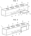
FIGS. 1 and 2 are external views illustrating a first configuration example of amobile printer 1 according to at least one embodiment. - In the configuration examples illustrated in
FIGS. 1 and 2 , themobile printer 1 includes acasing 10, a decolorizing device (translucent heater) 11, aprint head 12, apower button 13, atemperature switching button 14, aheating button 15, and aprint button 16,rollers sensor 19. - The decolorizing
device 11 is a translucent device that decolorizes the thermochromic colorant. The decolorizingdevice 11 is configured so that the top of the recording medium can be seen through when pressed against the recording medium. That is, the decolorizingdevice 11 is configured so that the user can directly see the portion pressed for decolorizing the thermochromic colorant. The decolorizingdevice 11 includes, for example, a translucent substrate 21 (e.g., seeFIGS. 5 and 6 ) that is heated by heat from a translucent heat source. Thetranslucent substrate 21 of the decolorizingdevice 11 reaches a temperature (e.g., decolorizing temperature) at which the thermochromic colorant is decolorized by heat from a heat source. When a front surface (e.g., decolorizing surface) of thetranslucent substrate 21 that reaches the decolorizing temperature is pressed against the recording medium, the thermochromic colorant on the recording medium decolorizes. - The
casing 10 is a casing to which each part such as the decolorizingdevice 11, thepower button 13, thetemperature switching button 14, and theheating button 15 is attached. Theprint head 12, therollers sensor 19 are provided in thecasing 10. A controller 30 (e.g., seeFIG. 7 ) and a battery 40 (seeFIG. 7 ) are also provided in thecasing 10. - The
casing 10 is a handle that the user grips. The user moves the bottom surface of the grippedcasing 10 on the recording medium. Themobile printer 1 decolorizes the thermochromic colorant on the recording medium or forms an image on the recording medium by moving (scanning) thecasing 10 on the recording medium by the user. - The
casing 10 is provided with asupport mechanism 101 that holds the decolorizingdevice 11 in a decolorizing position or an accommodating position.FIG. 1 illustrates a state in which thedecolorizing device 11 is in the decolorizing position.FIG. 2 illustrates a state in which thedecolorizing device 11 is in the accommodating position. In the configuration examples illustrated inFIGS. 1 and 2 , the decolorizingdevice 11 rotates with respect to thecasing 10 about a fulcrum of thesupport mechanism 101. - The
support mechanism 101 includes a lock mechanism that locks the decolorizingdevice 11 at the decolorizing position or the accommodating position. The lock mechanism included in thesupport mechanism 101 may be any lock mechanism that can be locked or unlocked by user operation. For example, the decolorizingdevice 11 locked at the decolorizing position is unlocked and moved to the accommodating position by the user moving thecasing 10 so as to be folded with respect to thecasing 10. The decolorizing device locked at the accommodating position is unlocked and moved to the decolorizing position by an operation of the user. - At the decolorizing position illustrated in
FIG. 1 , the decolorizingdevice 11 is fixed at a position where the decolorizing surface pressed against the recording medium is on the same surface as the bottom surface of thecasing 10. When the bottom surface of thecasing 10 is moved while being abutted on the recording medium, the decolorizing surface of the decolorizingdevice 11 also moves on the recording medium. The decolorizingdevice 11 is configured with a translucent device. For that reason, the user can directly visually recognize the position (decolorizing position) where the decolorizing surface of the decolorizingdevice 11 abuts on. As a result, the user can move the decolorizing surface which is on the same surface as the bottom surface of thecasing 10 by pressing the decolorizing surface against the recording medium while checking the decolorizing position. - In the accommodating position illustrated in
FIG. 2 , the decolorizingdevice 11 is held in an accommodating position where the decolorizing surface is parallel to a side surface of thecasing 10. When the decolorizingdevice 11 is accommodated in the accommodating position, themobile printer 1 can reduce a bottom area (area of a bottom surface including the bottom surface of thecasing 10 and the decolorizing surface of the decolorizing device 11). By holding the decolorizingdevice 11 in the accommodating position, the decolorizingdevice 11 can be prevented from becoming bulky, and themobile printer 1 can be easily carried around. - The
mobile printer 1 is configured so that power can be supplied to thedecolorizing device 11 located at the decolorizing position and power cannot be supplied to thedecolorizing device 11 located at the accommodating position. The decolorizingdevice 11 is electrically connected to the controller 30 (seeFIG. 7 ) or the like in thecasing 10, at the decolorizing position as illustrated inFIG. 1 . The electrical connection of the decolorizingdevice 11 with the controller 30 (seeFIG. 7 ) or the like in thecasing 10 is disconnected at the accommodating position as illustrated inFIG. 2 . With this configuration, in themobile printer 1, power is not supplied to thedecolorizing device 11 located at the accommodating position, and theprinter 1 can be safely carried and stored. - The
support mechanism 101 is not limited to a mechanism that rotates the decolorizingdevice 11 with respect to thecasing 10. Thesupport mechanism 101 may be any mechanism as long as the mechanism can hold thedecolorizing device 11 at the decolorizing position and the accommodating position. For example, thesupport mechanism 101 may be a mechanism that slides the decolorizingdevice 11 to be accommodated in the accommodating position in thecasing 10. Thesupport mechanism 101 may be a mechanism capable of removing the decolorizingdevice 11. - The
print head 12 forms an image on the recording medium. For example, theprint head 12 is an inkjet head. In at least one embodiment, theprint head 12 discharges ink made of a thermochromic colorant. However, theprint head 12 may selectively discharge the ink of the thermochromic colorant and other inks. Theprint head 12 is attached to thecasing 10 so as to discharge ink onto the recording medium from the bottom surface of thecasing 10. - The
print head 12 is configured to print a plurality of pixels in the main scanning direction. A width (e.g., print width) to be printed by theprint head 12 in the main scanning direction and a width (e.g., decolorizing width) to be decolorized by the decolorizingdevice 11 in the main scanning direction are formed to be the same width. - In the configuration example illustrated in
FIG. 1 , the decolorizingdevice 11 is disposed so as to be upstream of theprint head 12 in the sub-scanning direction. When thecasing 10 moves in the sub-scanning direction, the decolorizing width W of the decolorizingdevice 11 is formed to be the same as the print width W of theprint head 12. In themobile printer 1 illustrated inFIG. 1 , when thecasing 10 is moved in the sub-scanning direction, theprint head 12 can print an image in a region that has been decolorized by the decolorizingdevice 11. - The decolorizing
device 11 may be provided on both sides of thecasing 10 so as to sandwich theprint head 12. For example, in the example illustrated inFIG. 1 , another decolorizing device having the same decolorizing width as the print width W may be provided on a side surface opposite to the side surface of thecasing 10 to which thedecolorizing device 11 is attached. When two decolorizing devices are provided so as to sandwich theprint head 12, control may be made such that any decolorizing device can be used according to the moving direction of thecasing 10. - The
rollers casing 10. Therollers print head 12. Therollers casing 10 to the sub-scanning direction when the bottom surface of thecasing 10 moves to the recording medium. - The
sensor 19 detects the movement of thecasing 10. Thesensor 19 detects an amount of movement in the sub-scanning direction. For example, thesensor 19 may detect the amount of movement in the sub-scanning direction by detecting an amount of rotation of theroller 17 or theroller 18. Thesensor 19 may be an acceleration sensor or the like. - The
power button 13, thetemperature switching button 14, theheating button 15, and theprint button 16 are disposed side by side on the upper surface of thecasing 10. Thepower button 13, thetemperature switching button 14, theheating button 15, and theprint button 16 may be provided anywhere in thecasing 10 as long as the buttons are in a position where the user can press the buttons. - The
power button 13 is a button for switching ON and OFF of the power. Themobile printer 1 switches ON and OFF of the power according to the state of thepower button 13. For example, themobile printer 1 may be turned ON in a state where thepower button 13 is pressed in. Themobile printer 1 may switch ON and OFF of the power depending on the number of times thepower button 13 is pressed. Themobile printer 1 may switch ON and OFF of the power according to the time during which thepower button 13 is pressed. - The
temperature switching button 14 is a button for designating a set temperature of the decolorizing surface in thedecolorizing device 11. For example, in a state where thetemperature switching button 14 is pressed in, the decolorizing surface of the decolorizingdevice 11 is set to be a first temperature. In a state where thetemperature switching button 14 is not pressed in, the decolorizing surface of the decolorizingdevice 11 is set to a second temperature different from the first temperature. - The
heating button 15 is a button for switching ON and OFF of heating to the decolorizing surface of the decolorizingdevice 11. For example, the decolorizingdevice 11 is controlled to heat the decolorizing surface while theheating button 15 is pressed. When theheating button 15 is not pressed, the decolorizingdevice 11 is controlled to turn OFF heating to the decolorizing surface. Theheating button 15 may include a mechanism for holding theheating button 15 in a pressed state. By holding theheating button 15 in the pressed state, the decolorizingdevice 11 is kept in a continuous state of heating the decolorizing surface. - The
print button 16 is a button for switching ON and OFF of image formation by theprint head 12. For example, when theprint button 16 is pressed, theprint head 12 is controlled to print image data according to the movement of thecasing 10. While theprint button 16 is pressed, theprint head 12 is controlled to form an image according to the movement of thecasing 10. When theprint button 16 is not pressed, theprint head 12 may be controlled so as not to discharge ink from theprint head 12. -
FIGS. 3 and 4 are external views illustrating a second configuration example of themobile printer 1 according to at least one embodiment. - A
mobile printer 2 illustrated inFIGS. 3 and 4 is a modification of themobile printer 1 illustrated inFIGS. 1 and 2 . Themobile printer 2 is different from themobile printer 1 in an attaching position of the decolorizing device (translucent heater) 11 with respect to thecasing 10. Since themobile printer 2 has the same configuration as themobile printer 1 except for the attaching position of the decolorizingdevice 11, the same reference numerals are given to the same parts and the detailed description thereof will be omitted. - The
mobile printer 2 is configured so that a region to be printed by theprint head 12 and a region to be decolorized by the decolorizingdevice 11 do not overlap when thecasing 10 is moved in the sub-scanning direction. However, as illustrated inFIG. 3 , also in themobile printer 2, the decolorizingdevice 11 may be designed so that the decolorizing width W is the same as the print width of theprint head 12. - In the example illustrated in
FIGS. 3 and 4 , in themobile printer 2, the decolorizingdevice 11 is supported on the side surface of theprint head 12 in thecasing 10 in the main scanning direction through thesupport mechanism 101. In themobile printer 2, the decolorizingdevice 11 rotates about the fulcrum of thesupport mechanism 101 with respect to the side surface of theprint head 12 in thecasing 10 in the main scanning direction. -
FIG. 3 illustrates a state in which thedecolorizing device 11 is in the decolorizing position of themobile printer 2. At the decolorizing position illustrated inFIG. 3 , the decolorizingdevice 11 is fixed at a position where the decolorizing surface is on the same surface as the bottom surface of thecasing 10. In themobile printer 2, when the bottom surface of thecasing 10 is moved while being abutted on the recording medium, the decolorizing surface of the decolorizingdevice 11 also moves on the recording medium. Also in themobile printer 2, the decolorizingdevice 11 is configured with a translucent member. For that reason, in themobile printer 2, the user can directly visually recognize the position (decolorizing position) where the decolorizing surface of the decolorizingdevice 11 abuts on, similar to themobile printer 1. -
FIG. 4 illustrates a state in which thedecolorizing device 11 is in the accommodating position of themobile printer 2. Themobile printer 2 holds the decolorizingdevice 11 in the accommodating position illustrated inFIG. 4 . When the decolorizingdevice 11 is accommodated in the accommodating position, themobile printer 2 can reduce the bottom area (area of the bottom surface including the bottom surface of thecasing 10 and the decolorizing surface of the decolorizing device 11), similar to themobile printer 1. By holding the decolorizingdevice 11 in the accommodating position, the decolorizingdevice 11 can be prevented from becoming bulky, and themobile printer 2 can be easily carried around. Similar to themobile printer 1, themobile printer 2 is configured so that power is not supplied to thedecolorizing device 11 located at the accommodating position. - Next, the configuration of the decolorizing
device 11 included in themobile printer -
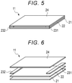
FIG. 5 is a diagram illustrating a configuration example of the decolorizingdevice 11 included in themobile printer FIG. 6 is a diagram illustrating parts configuring the decolorizingdevice 11 illustrated inFIG. 5 . - As illustrated in
FIGS. 5 and 6 , the decolorizingdevice 11 includes thetranslucent substrate 21, atranslucent film 22, electrodes 23 (first electrode 231 and second electrode 232), and an insulatinglayer 24. - The
translucent substrate 21 is a translucent substrate such as a glass substrate or a PET film. Thetranslucent film 22 is a translucent film having conductivity such as an indium tin oxide (ITO) film. Thetranslucent film 22 has electrical resistance (sheet resistance). For example, thetranslucent film 22 is formed on thetranslucent substrate 21 by vapor deposition. - The
first electrode 231 and thesecond electrode 232 are connected to thetranslucent film 22. The translucent insulatinglayer 24 such as a glass cover is formed on thetranslucent film 22 to which the electrodes 23 are connected. Thefirst electrode 231 and thesecond electrode 232 are connected to a heater drive circuit 35 (seeFIG. 7 ), which will be described later. When a voltage is applied between thefirst electrode 231 and thesecond electrode 232, a current flows through thetranslucent film 22, and Joule heat is generated due to sheet resistance. The Joule heat generated in thetranslucent film 22 heats thetranslucent substrate 21. The heatedtranslucent substrate 21 gives heat to an object in contact with the surface thereof (decolorizing surface). - Next, a configuration of a control system in the
mobile printer -
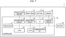
FIG. 7 is a block diagram illustrating a configuration example of the control system in themobile printer - As illustrated in
FIG. 7 , themobile printer controller 30 and thebattery 40. Thecontroller 30 and thebattery 40 are provided in thecasing 10. Thecontroller 30 is connected to thedecolorizing device 11, theprint head 12,various buttons 13 to 16, thesensor 19, and thebattery 40. - The
controller 30 controls the driving of themobile printer buttons 13 to 16. Thebattery 40 provides energy for heating the heat source of the decolorizingdevice 11. Thebattery 40 is a rechargeable secondary battery built in thecasing 10. Thecasing 10 may be provided with a battery box to and from which a battery as thebattery 40 can be attached and detached. - The
controller 30 includes aprocessor 31, aROM 32, aRAM 33, a communication interface (I/F) 34, theheater drive circuit 35, ahead drive circuit 36, aninterface 37, and asensor circuit 38. Power is supplied to thecontroller 30 from thebattery 40. Themobile printer battery 40. - The
processor 31 controls each unit and the like. Theprocessor 31 is, for example, a CPU. Theprocessor 31 executes a program for controlling each part. Theprocessor 31 is connected to theROM 32, theRAM 33, the communication interface (I/F) 34, theheater drive circuit 35, thehead drive circuit 36, theinterface 37, and thesensor circuit 38 via a bus. TheROM 32 is a non-volatile memory for storing a program. TheRAM 33 is a working memory that temporarily stores data. - The
communication interface 34 is an interface for communicating with an external device. For example, thecommunication interface 34 acquires image data of an image formed on the recording medium by theprint head 12. Thecommunication interface 34 may acquire a control signal from the external device. - The
heater drive circuit 35 includes a circuit that drives the decolorizingdevice 11. Theheater drive circuit 35 controls the driving of the decolorizing device according to a control signal from theprocessor 31. For example, theheater drive circuit 35 applies a voltage of a value designated by theprocessor 31 according to the set temperature between theelectrodes 231 and 232 (translucent film 22). - The
head drive circuit 36 includes a circuit that drives theprint head 12. Thehead drive circuit 36 controls driving of theprint head 12 according to the control signal from theprocessor 31. For example, thehead drive circuit 36 drives theprint head 12 according to the control signal from theprocessor 31. - The
interface 37 connects thebuttons 13 to 16. Theprocessor 31 acquires a signal indicating the state of each of thebuttons 13 to 16 via theinterface 37. - The
sensor circuit 38 acquires a detection signal of thesensor 19. For example, thesensor circuit 38 supplies a signal indicating the amount of movement in the sub-scanning direction detected by thesensor 19 to theprocessor 31. - Next, a relationship between a voltage to be applied to the
translucent film 22 of the decolorizingdevice 11 and a temperature occurring on the surface of thetranslucent substrate 21 of the decolorizingdevice 11 will be described. -
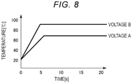
FIG. 8 is a diagram illustrating the relationship between the temperature and the time, which occurs when two types of voltages are applied to the translucent film 22 (electrodes 231 and 232) of the decolorizingdevice 11. -
FIG. 8 illustrates a temperature change when a voltage A is applied to thetranslucent film 22 of the decolorizingdevice 11 and a temperature change when a voltage B larger than the voltage A is applied to thetranslucent film 22. As illustrated inFIG. 8 , when a voltage is applied to thetranslucent film 22 of the decolorizingdevice 11, the temperature of thetranslucent substrate 21 rises. The temperature of thetranslucent substrate 21 reaches a predetermined temperature several seconds after the voltage is applied. In the example illustrated inFIG. 8 , when the voltage A is applied, the temperature of thetranslucent substrate 21 becomes about 70°C after six to seven seconds. When the voltage B is applied, the temperature of thetranslucent substrate 21 becomes about 90°C after five to six seconds. - In at least one embodiment, it is assumed that the
mobile printer translucent substrate 21. Theprocessor 31 of thecontroller 30 sets the temperature of thetranslucent substrate 21 according to the state of thetemperature switching button 14. As illustrated inFIG. 8 , the temperature of thetranslucent substrate 21 is determined by a voltage value to be applied to thetranslucent film 22. For that reason, theprocessor 31 of thecontroller 30 sets the voltage value to be applied to thedecolorizing device 11 by theheater drive circuit 35 according to the state of thetemperature switching button 14. - For example, the temperature set by the
temperature switching button 14 is switched according to the object to be decolorized. Some thermochromic colorants have different decolorizing temperatures for decolorizing (decolorizing). As a specific example, it is assumed that a first colorant is decolorized at a temperature higher than a first decolorizing temperature and a second colorant is decolorized at a second decolorizing temperature higher than the first decolorizing temperature. In this case, at a temperature equal to or higher than the first decolorizing temperature and lower than the second decolorizing temperature, the second colorant is not decolorized but the first colorant is decolorized. At a temperature equal to and higher than the second decolorizing temperature, both the second colorant and the first colorant are decolorized. The user can designate either a setting for decolorizing the first colorant without decolorizing the second colorant or a setting for decolorizing both the first colorant and the second colorant with thetemperature switching button 14. - Actually, the thermochromic colorant on the recording medium is decolorized by heat applied to the recording medium from the surface of the
translucent substrate 21. For that reason, the user may switch the setting of temperature with thetemperature switching button 14 according to the situation to be used. For example, when the user wants to quickly move thedecolorizing device 11 to decolorize the thermochromic colorant on the recording medium, the user may set the temperature higher with thetemperature switching button 14. When the user does not want to give the recording medium as high a temperature as possible, the user may set the temperature lower with thetemperature switching button 14 to slowly move thedecolorizing device 11. - Next, the operations of the
mobile printers - Here, it is assumed that the
mobile printers device 11 without printing by theprint head 12. The decolorizing and printing mode is an operation mode in which theprint head 12 prints on the region which has been decolorized by the decolorizingdevice 11. - First, the operation in the decolorizing mode of the
mobile printers -
FIG. 9 is a flowchart for describing an operation example in the decolorizing mode of themobile printers - When it is determined that the operation mode is the decolorizing mode (YES in ACT 11), the
processor 31 of thecontroller 30 determines whether the decolorizingdevice 11 is in a usable state (ACT 12). For example, when the decolorizingdevice 11 is in the decolorizing position as illustrated inFIG. 1 or3 , theprocessor 31 determines that the decolorizingdevice 11 is in the usable state. When the decolorizingdevice 11 is in the accommodating position as illustrated inFIG. 2 or4 , theprocessor 31 determines that the decolorizingdevice 11 is in an unusable state. Theprocessor 31 may determine whether or not the decolorizingdevice 11 is in the usable state depending on whether or not the decolorizingdevice 11 is electrically connected to thecontroller 30. - When it is determined that the decolorizing
device 11 is in the unusable state (NO in ACT 12), theprocessor 31 waits for thedecolorizing device 11 to become the usable state. Themobile printer 1 may be provided with an indicator such as an LED indicating whether the decolorizingdevice 11 is in the usable state or the unusable state. When it is determined that the decolorizingdevice 11 is in the unusable state, theprocessor 31 may cause the indicator to indicate that the decolorizingdevice 11 is in the unusable state. - When it is determined that the decolorizing
device 11 is in the usable state (YES in ACT 12), theprocessor 31 sets the temperature of thetranslucent substrate 21 having the decolorizing surface according to the state of the temperature switching button 14 (ACT 13). For example, theprocessor 31 detects the state of thetemperature switching button 14. When thetemperature switching button 14 is in the state of designating the first temperature, theprocessor 31 sets a voltage value corresponding to the first temperature in theheater drive circuit 35 as a voltage value to be applied to thedecolorizing device 11. When thetemperature switching button 14 is in the state of designating the second temperature, theprocessor 31 sets a voltage value corresponding to the second temperature in theheater drive circuit 35 as a voltage value to be applied to thedecolorizing device 11. - After setting the temperature according to the state of the
temperature switching button 14, theprocessor 31 determines whether or not to heat thetranslucent substrate 21 of the decolorizing device 11 (ACT 14). For example, theprocessor 31 determines to heat thetranslucent substrate 21 if theheating button 15 is pressed, and determines not to heat thetranslucent substrate 21 if theheating button 15 is not pressed. In this case, theprocessor 31 detects the state of theheating button 15 and determines whether or not to heat thetranslucent substrate 21 according to the state of theheating button 15. - When it is determined to heat the translucent substrate 21 (YES in ACT 14), the
processor 31 applies a voltage of a value set according to the state of thetemperature switching button 14 to theelectrodes 231 and 232 (translucent film 22) of the decolorizing device 11 (ACT 15). For example, theprocessor 31 causes a voltage to be applied to theelectrodes heater drive circuit 35 in which the voltage value to be applied is set according to the state of thetemperature switching button 14. - When it is determined not to heat the translucent substrate 21 (NO in ACT 14), the
processor 31 cuts off the voltage applied to theelectrodes processor 31 stops the application of the voltage from theheater drive circuit 35 to theelectrodes device 11. - While the operation mode is the decolorizing mode (NO in ACT 17), the
processor 31 repeatedly executes the processing ofACTs 12 to 16. When the power OFF is instructed through thepower button 13 or when a change to an operation mode other than the decolorizing mode is instructed, theprocessor 31 determines to terminate the decolorizing mode. When it is determined to terminate the decolorizing mode (YES in ACT 17), theprocessor 31 ends the operation in the decolorizing mode. - As described above, the mobile printer according to at least one embodiment has the decolorizing mode for decolorizing the thermochromic colorant on the recording medium using the decolorizing device with respect to the recording medium. Since the decolorizing device is translucent, the user can move the casing while checking the place to be decolorized, and decolorizing the desired region can be surely performed.
- Next, the operation in the decolorizing and printing mode of the
mobile printer 1 will be described. -
FIG. 10 is a flowchart for describing an operation example in the decolorizing and printing mode in themobile printer 1. - When it is determined that the operation mode is the decolorizing and printing mode (YES in ACT 31), the
processor 31 of thecontroller 30 determines whether the decolorizingdevice 11 is in a usable state (ACT 32). For example, when the decolorizingdevice 11 is in the decolorizing position as illustrated inFIG. 1 , theprocessor 31 determines that the decolorizingdevice 11 is in the usable state. When the decolorizingdevice 11 is in the accommodating position as illustrated inFIG. 2 , theprocessor 31 determines that the decolorizingdevice 11 is in an unusable state. Theprocessor 31 may determine whether or not the decolorizingdevice 11 is in the usable state depending on whether or not the decolorizingdevice 11 is electrically connected to thecontroller 30. - When it is determined that the decolorizing
device 11 is in the unusable state (NO in ACT 32), theprocessor 31 waits for thedecolorizing device 11 to become the usable state. - When it is determined that the decolorizing
device 11 is in the usable state (YES in ACT 32), theprocessor 31 sets the temperature of thetranslucent substrate 21 having the decolorizing surface according to the state of the temperature switching button 14 (ACT 33). For example, theprocessor 31 detects the state of thetemperature switching button 14. When thetemperature switching button 14 is in the state of designating the first temperature, theprocessor 31 sets a voltage value corresponding to the first temperature in theheater drive circuit 35 as a voltage value to be applied to thedecolorizing device 11. When thetemperature switching button 14 is in the state of designating the second temperature, theprocessor 31 sets a voltage value corresponding to the second temperature in theheater drive circuit 35 as a voltage value to be applied to thedecolorizing device 11. - After setting the temperature according to the state of the
temperature switching button 14, theprocessor 31 determines whether or not to heat thetranslucent substrate 21 of the decolorizing device 11 (ACT 34). For example, theprocessor 31 detects the state of theheating button 15 and determines whether or not to heat thetranslucent substrate 21 according to the state of theheating button 15. - When it is determined to heat the translucent substrate 21 (YES in ACT 34), the
processor 31 applies a voltage of a value set according to the state of thetemperature switching button 14 to theelectrodes 231 and 232 (translucent film 22) of the decolorizing device 11 (ACT 35). Theprocessor 31 applies the voltage of the set voltage value to thetranslucent film 22 of the decolorizingdevice 11 using theheater drive circuit 35. - When it is determined not to heat the translucent substrate 21 (NO in ACT 34), the
processor 31 cuts off the voltage to be applied to theelectrodes processor 31 stops the application of the voltage from theheater drive circuit 35 to thetranslucent film 22 of the decolorizingdevice 11. - In the decolorizing and printing mode, the
processor 31 acquires image data to be printed on the recording medium using theprint head 12 through the communication interface 34 (ACT 37). Theprocessor 31 stores the image data acquired through thecommunication interface 34 in a memory such as theRAM 33. In the decolorizing and printing mode, theprocessor 31 detects the movement of thecasing 10 based on the detection signal of the sensor 19 (ACT 38). For example, theprocessor 31 acquires the detection signal of thesensor 19 by thesensor circuit 38. Theprocessor 31 detects the amount of movement of thecasing 10 in the sub-scanning direction with respect to the main scanning direction of theprint head 12, based on the detection signal of thesensor 19 acquired by thesensor circuit 38. - The
processor 31 determines whether or not thecasing 10 is moved in the sub-scanning direction. When the movement of thecasing 10 in the sub-scanning direction is detected (YES in ACT 39), theprocessor 31 prints the image data on the recording medium using theprint head 12. Theprocessor 31 drives theprint head 12 by thehead drive circuit 36 according to the detected movement amount in the sub-scanning direction and the image data. Thehead drive circuit 36 causes ink containing a thermochromic colorant to be discharged from each pixel of theprint head 12 according to the control from theprocessor 31. - Here, in the
mobile printer 1 illustrated inFIG. 1 , the decolorizingdevice 11 is disposed upstream of theprint head 12 in the sub-scanning direction. Themobile printer 1 is designed so that the width to be decolorized by the decolorizingdevice 11 and the width to be printed by theprint head 12 are the same in the main scanning direction. In themobile printer 1, when thecasing 10 moves in the sub-scanning direction, theprint head 12 prints each pixel based on the image data in the region which has been decolorized by the decolorizingdevice 11. - The
processor 31 monitors whether or not the printing of the image based on the image data acquired via thecommunication interface 34 was completed (ACT 41). When it is determined that the printing of the image based on the acquired image data is not completed (NO in ACT 41), theprocessor 31 repeatedly executes the processing ofACTs 32 to 40. When it is determined that the printing of the image based on the image data was completed (YES in ACT 41), theprocessor 31 ends the printing of the image in the decolorizing and printing mode. - As described above, the mobile printer according to at least one embodiment has the decolorizing and printing mode in which the decolorizing device prints an image on the recording medium with the print head while decolorizing the thermochromic colorant. Since the decolorizing device is translucent, the user can move the casing while checking the place to be decolorized, and decolorizing and printing to a desired region can be performed in one operation.
- The mobile printer according to at least one embodiment may have a configuration in which the decolorizing device is disposed upstream of the print head in the sub-scanning direction. In the mobile printer having such a configuration, by moving the casing in the sub-scanning direction by the user, the image can be printed by the print head on the region after having been decolorized by the decolorizing device.
- The mobile printer according to at least one embodiment may be configured so that the decolorizing width of the decolorizing
device 11 and the print width of theprint head 12 in the main scanning direction are the same. In the mobile printer having such a configuration, the region to be decolorized by the decolorizing device and the region to be printed by the print head can be the same region when the casing moves in the sub-scanning direction. - While certain embodiments have been described, these embodiments have been presented by way of example only, and are not intended to limit the scope of the inventions. Indeed, the novel embodiments described herein may be embodied in a variety of other forms. Furthermore, various omissions, substitutions and changes in the form of the embodiments described herein may be made without departing from the scope of the inventions. The accompanying claims and their equivalents are intended to cover such forms or modifications as would fall within the scope of the inventions.
Claims (15)
- A mobile printer comprising:a casing configured to receive a power supply;a sensor configured to detect movement of the casing;a print head configured to discharge ink containing a thermochromic colorant;an interface configured to acquire image data;a controller configured to cause the ink to be discharged from the print head based on the image data acquired by the interface and the movement of the casing detected by the sensor; anda decolorizing device configured to couple to the casing, including a translucent film configured to generate heat when a voltage is applied, and a translucent substrate configured to be heated to a temperature at which the thermochromic colorant is decolorized by the heat generated by the translucent film.
- The printer of claim 1, further comprising a support mechanism configured to hold the decolorizing device to the casing so as to be movable between an accommodating position and a discoloration position.
- The printer of claim 2, wherein the controller is configured to determine that the decolorizing device is in a usable state when the decolorizing device is in the decolorizing position.
- The printer of claim 2, wherein the controller is configured to determine that the decolorizing device is in an unusable state when the decolorizing device is in the accommodating position.
- The printer according to any one of claims 1 to 4, further comprising a temperature switching button configured to designate temperature.
- The printer of claim 5, wherein the controller is configured to control a value of the voltage to be applied to the translucent film of the decolorizing device according to the temperature designated by the temperature switching button.
- The printer according to any one of claims 1 to 6, further comprising a roller configured to regulate a moving direction of the casing in a sub-scanning direction with respect to a main scanning direction of the print head.
- The printer of claim 7, wherein the controller is configured to apply the voltage to the translucent film of the decolorizing device located upstream of the print head in the sub-scanning direction.
- The printer of claim 8, wherein the decolorizing device is configured so that the width of the translucent substrate in the main scanning direction when coupled to the casing is the same as the print width of the print head in the main scanning direction.
- The printer according to any one of claims 1 to 9, wherein the controller is configured to cause a voltage A to be applied to the translucent film to increase the temperature of the translucent film and the translucent substrate, and to cause a voltage B larger than the voltage A to be applied to the translucent film to increase the temperature of the translucent film and the translucent substrate.
- A method of operating a mobile printer, the method comprising:detecting movement, via a sensor, of a casing;acquiring image data, via an interface;discharging ink, via a print head, based on the image data acquired by the interface and the movement of the casing detected by the sensor;applying a voltage to generate heat at a translucent film when the voltage is applied; andheating a translucent substrate to a temperature by the heat generated by the translucent film to decolorize a thermochromic colorant of the ink.
- The method of claim 11, further comprising holding a decolorizing device to the casing, via a support mechanism, so as to be movable between an accommodating position and a discoloration position,
wherein the decolorizing device comprises the translucent film and the translucent substrate. - The method of claim 12, further comprising determining that the decolorizing device is in a usable state when the decolorizing device is in the decolorizing position and in an unusable state when the decolorizing device is in the accommodating position.
- The method according to any one of claims 11 to 13, further comprising:designating a temperature, via a temperature switching button; andcontrolling a value of the voltage to be applied to the translucent film of the decolorizing device according to the temperature designated by the temperature switching button.
- The method according to any one of claims 11 to 14, further comprising:regulating a moving direction of the casing, via a roller, in a sub-scanning direction with respect to a main scanning direction of the print head; andapplying the voltage to the translucent film of the decolorizing device located upstream of the print head in the sub-scanning direction.
Applications Claiming Priority (1)
| Application Number | Priority Date | Filing Date | Title |
|---|---|---|---|
| JP2020149666A JP7499122B2 (en) | 2020-09-07 | 2020-09-07 | Mobile Printer |
Publications (2)
| Publication Number | Publication Date |
|---|---|
| EP3964364A1 true EP3964364A1 (en) | 2022-03-09 |
| EP3964364B1 EP3964364B1 (en) | 2024-04-17 |
Family
ID=76662352
Family Applications (1)
| Application Number | Title | Priority Date | Filing Date |
|---|---|---|---|
| EP21178291.7A Active EP3964364B1 (en) | 2020-09-07 | 2021-06-08 | Mobile printer |
Country Status (4)
| Country | Link |
|---|---|
| US (1) | US11504976B2 (en) |
| EP (1) | EP3964364B1 (en) |
| JP (1) | JP7499122B2 (en) |
| CN (1) | CN114148086B (en) |
Families Citing this family (1)
| Publication number | Priority date | Publication date | Assignee | Title |
|---|---|---|---|---|
| JP7476043B2 (en) * | 2020-09-07 | 2024-04-30 | 東芝テック株式会社 | Color changing device |
Citations (6)
| Publication number | Priority date | Publication date | Assignee | Title |
|---|---|---|---|---|
| US20020158955A1 (en) * | 2001-04-30 | 2002-10-31 | Hess Jeffery S. | Floor Printer |
| US20120044278A1 (en) * | 2009-04-30 | 2012-02-23 | Sangmoon Hwang | Display apparatus |
| US20130271547A1 (en) * | 2012-04-16 | 2013-10-17 | Toshiba Tec Kabushiki Kaisha | Image forming device |
| EP3007011A1 (en) * | 2014-10-06 | 2016-04-13 | Kabushiki Kaisha Toshiba | Image forming apparatus |
| EP3418062A1 (en) * | 2017-06-21 | 2018-12-26 | Fujitsu Component Limited | Printing apparatus |
| EP3620305A1 (en) * | 2018-09-10 | 2020-03-11 | Ricoh Company, Ltd. | Image forming apparatus |
Family Cites Families (19)
| Publication number | Priority date | Publication date | Assignee | Title |
|---|---|---|---|---|
| JPH05127153A (en) * | 1991-10-31 | 1993-05-25 | Canon Inc | Transparent panel heater |
| JPH08320463A (en) | 1995-05-25 | 1996-12-03 | Dainippon Printing Co Ltd | Information reproducing / erasing device |
| US6527462B2 (en) * | 2001-03-22 | 2003-03-04 | Brinwaves, Inc. | Device for dating notes |
| JP2005014575A (en) | 2003-06-25 | 2005-01-20 | Afuitsuto:Kk | Method for driving thermal head |
| CN101186146A (en) * | 2006-11-15 | 2008-05-28 | 明基电通信息技术有限公司 | Photochromicsm printing method, system and device |
| US8284221B2 (en) * | 2009-05-14 | 2012-10-09 | Kabushiki Kaisha Toshiba | Erasing device, image forming apparatus, and erasing method |
| JP5692519B2 (en) * | 2010-06-21 | 2015-04-01 | Nltテクノロジー株式会社 | Image display device, electronic apparatus using the same, display output control method for image display device, and output control program thereof |
| JP5032639B2 (en) | 2010-08-11 | 2012-09-26 | 雅昭 三原 | Thermochromic ink eraser |
| US11207913B2 (en) | 2012-12-05 | 2021-12-28 | Mitsubishi Pencil Company, Limited | Erasing member and erasing tool using the same |
| JP6198420B2 (en) | 2013-03-15 | 2017-09-20 | 三菱鉛筆株式会社 | Eraser |
| JP6171588B2 (en) * | 2013-06-05 | 2017-08-02 | コニカミノルタ株式会社 | Image forming apparatus |
| JP6347358B2 (en) | 2013-11-27 | 2018-06-27 | 昭生 荒木 | Thermochromic writing instrument |
| JP6052682B2 (en) | 2014-02-10 | 2016-12-27 | 昭生 荒木 | Heating device for thermochromic ink. |
| US9434193B2 (en) * | 2014-12-29 | 2016-09-06 | Kabushiki Kaisha Toshiba | Decoloring apparatus and method |
| EP3112182A1 (en) | 2015-06-30 | 2017-01-04 | Dong-A Pencil Co., Ltd. | Heating eraser for removing thermally changeable ink |
| CN105538970A (en) | 2016-01-04 | 2016-05-04 | 高龙杰 | Electrically-heated eraser for erasable pen |
| US10717313B2 (en) | 2016-03-28 | 2020-07-21 | Nucoat, Inc. | Heated writing device for use with thermochromatic ink |
| JP7040040B2 (en) | 2018-01-22 | 2022-03-23 | カシオ計算機株式会社 | Printing equipment, printing support methods and programs |
| JP2020040274A (en) * | 2018-09-10 | 2020-03-19 | 株式会社リコー | Portable image forming device |
-
2020
- 2020-09-07 JP JP2020149666A patent/JP7499122B2/en active Active
-
2021
- 2021-04-21 CN CN202110429174.XA patent/CN114148086B/en active Active
- 2021-04-23 US US17/239,203 patent/US11504976B2/en active Active
- 2021-06-08 EP EP21178291.7A patent/EP3964364B1/en active Active
Patent Citations (6)
| Publication number | Priority date | Publication date | Assignee | Title |
|---|---|---|---|---|
| US20020158955A1 (en) * | 2001-04-30 | 2002-10-31 | Hess Jeffery S. | Floor Printer |
| US20120044278A1 (en) * | 2009-04-30 | 2012-02-23 | Sangmoon Hwang | Display apparatus |
| US20130271547A1 (en) * | 2012-04-16 | 2013-10-17 | Toshiba Tec Kabushiki Kaisha | Image forming device |
| EP3007011A1 (en) * | 2014-10-06 | 2016-04-13 | Kabushiki Kaisha Toshiba | Image forming apparatus |
| EP3418062A1 (en) * | 2017-06-21 | 2018-12-26 | Fujitsu Component Limited | Printing apparatus |
| EP3620305A1 (en) * | 2018-09-10 | 2020-03-11 | Ricoh Company, Ltd. | Image forming apparatus |
Also Published As
| Publication number | Publication date |
|---|---|
| JP7499122B2 (en) | 2024-06-13 |
| US20220072868A1 (en) | 2022-03-10 |
| JP2022044173A (en) | 2022-03-17 |
| EP3964364B1 (en) | 2024-04-17 |
| CN114148086B (en) | 2023-09-19 |
| CN114148086A (en) | 2022-03-08 |
| US11504976B2 (en) | 2022-11-22 |
Similar Documents
| Publication | Publication Date | Title |
|---|---|---|
| US10427426B2 (en) | Recording apparatus | |
| CN105291600B (en) | The control method of printing equipment and printing equipment | |
| US5669720A (en) | Thermal printer with minimized power difference between sequentially driven blocks of printing elements | |
| JP2010042513A (en) | Printer and control method thereof | |
| EP3964364B1 (en) | Mobile printer | |
| US20200079109A1 (en) | Image forming apparatus | |
| JP7070073B2 (en) | Recording device | |
| EP1658989A1 (en) | Thermal printing | |
| JPS63176162A (en) | Thermal transfer recorder | |
| US7014375B2 (en) | Thermal printer and method determining battery condition based on temperature | |
| US9294645B2 (en) | Image forming apparatus and method of operating image forming apparatus, configured to determine whether operating mode is executable based on charge remaining in battery | |
| EP3964366B1 (en) | Decolorizing apparatus | |
| JP5966919B2 (en) | A method for controlling the energization time of the thermal head at an unstable voltage. | |
| JP4377638B2 (en) | Recording device, ink remaining amount detecting device, and ink remaining amount detecting method | |
| JP4681725B2 (en) | Thermal printer | |
| EP4272971B1 (en) | PRINTING SYSTEM FOR PRINTING IN ONE OF SEVERAL POWER MODES AND CONTROL METHOD FOR A PRINTING DEVICE | |
| US20250042180A1 (en) | Label printer | |
| JP2005343046A (en) | Recording head and printer | |
| KR20140014019A (en) | Heater for use in melting solid ink and melter device for melting solid ink | |
| JP2023164090A (en) | Printers and printing programs | |
| US7456854B2 (en) | Thermal printer | |
| JP3687894B2 (en) | Printer | |
| US20220234364A1 (en) | Mobile printer | |
| JPS58153676A (en) | Thermal transfer printing device | |
| JPH0417794B2 (en) |
Legal Events
| Date | Code | Title | Description |
|---|---|---|---|
| PUAI | Public reference made under article 153(3) epc to a published international application that has entered the european phase |
Free format text: ORIGINAL CODE: 0009012 |
|
| STAA | Information on the status of an ep patent application or granted ep patent |
Free format text: STATUS: THE APPLICATION HAS BEEN PUBLISHED |
|
| AK | Designated contracting states |
Kind code of ref document: A1 Designated state(s): AL AT BE BG CH CY CZ DE DK EE ES FI FR GB GR HR HU IE IS IT LI LT LU LV MC MK MT NL NO PL PT RO RS SE SI SK SM TR |
|
| STAA | Information on the status of an ep patent application or granted ep patent |
Free format text: STATUS: REQUEST FOR EXAMINATION WAS MADE |
|
| 17P | Request for examination filed |
Effective date: 20220909 |
|
| RBV | Designated contracting states (corrected) |
Designated state(s): AL AT BE BG CH CY CZ DE DK EE ES FI FR GB GR HR HU IE IS IT LI LT LU LV MC MK MT NL NO PL PT RO RS SE SI SK SM TR |
|
| REG | Reference to a national code |
Ref country code: DE Ref legal event code: R079 Free format text: PREVIOUS MAIN CLASS: B41J0011000000 Ipc: B43L0013020000 Ref country code: DE Ref legal event code: R079 Ref document number: 602021011809 Country of ref document: DE Free format text: PREVIOUS MAIN CLASS: B41J0011000000 Ipc: B43L0013020000 |
|
| GRAP | Despatch of communication of intention to grant a patent |
Free format text: ORIGINAL CODE: EPIDOSNIGR1 |
|
| STAA | Information on the status of an ep patent application or granted ep patent |
Free format text: STATUS: GRANT OF PATENT IS INTENDED |
|
| RIC1 | Information provided on ipc code assigned before grant |
Ipc: B43L 19/00 20060101ALI20231019BHEP Ipc: B41M 7/00 20060101ALI20231019BHEP Ipc: B41J 11/00 20060101ALI20231019BHEP Ipc: B41J 3/36 20060101ALI20231019BHEP Ipc: G03G 21/00 20060101ALI20231019BHEP Ipc: B43L 13/02 20060101AFI20231019BHEP |
|
| INTG | Intention to grant announced |
Effective date: 20231107 |
|
| GRAS | Grant fee paid |
Free format text: ORIGINAL CODE: EPIDOSNIGR3 |
|
| GRAA | (expected) grant |
Free format text: ORIGINAL CODE: 0009210 |
|
| STAA | Information on the status of an ep patent application or granted ep patent |
Free format text: STATUS: THE PATENT HAS BEEN GRANTED |
|
| AK | Designated contracting states |
Kind code of ref document: B1 Designated state(s): AL AT BE BG CH CY CZ DE DK EE ES FI FR GB GR HR HU IE IS IT LI LT LU LV MC MK MT NL NO PL PT RO RS SE SI SK SM TR |
|
| REG | Reference to a national code |
Ref country code: GB Ref legal event code: FG4D |
|
| REG | Reference to a national code |
Ref country code: CH Ref legal event code: EP |
|
| REG | Reference to a national code |
Ref country code: DE Ref legal event code: R096 Ref document number: 602021011809 Country of ref document: DE |
|
| REG | Reference to a national code |
Ref country code: IE Ref legal event code: FG4D |
|
| REG | Reference to a national code |
Ref country code: LT Ref legal event code: MG9D |
|
| REG | Reference to a national code |
Ref country code: NL Ref legal event code: MP Effective date: 20240417 |
|
| REG | Reference to a national code |
Ref country code: DE Ref legal event code: R081 Ref document number: 602021011809 Country of ref document: DE Owner name: RISO TECHNOLOGIES CORP., JP Free format text: FORMER OWNER: TOSHIBA TEC KABUSHIKI KAISHA, TOKYO, JP |
|
| REG | Reference to a national code |
Ref country code: AT Ref legal event code: MK05 Ref document number: 1676912 Country of ref document: AT Kind code of ref document: T Effective date: 20240417 |
|
| PG25 | Lapsed in a contracting state [announced via postgrant information from national office to epo] |
Ref country code: NL Free format text: LAPSE BECAUSE OF FAILURE TO SUBMIT A TRANSLATION OF THE DESCRIPTION OR TO PAY THE FEE WITHIN THE PRESCRIBED TIME-LIMIT Effective date: 20240417 |
|
| PG25 | Lapsed in a contracting state [announced via postgrant information from national office to epo] |
Ref country code: NL Free format text: LAPSE BECAUSE OF FAILURE TO SUBMIT A TRANSLATION OF THE DESCRIPTION OR TO PAY THE FEE WITHIN THE PRESCRIBED TIME-LIMIT Effective date: 20240417 |
|
| PG25 | Lapsed in a contracting state [announced via postgrant information from national office to epo] |
Ref country code: IS Free format text: LAPSE BECAUSE OF FAILURE TO SUBMIT A TRANSLATION OF THE DESCRIPTION OR TO PAY THE FEE WITHIN THE PRESCRIBED TIME-LIMIT Effective date: 20240817 |
|
| PG25 | Lapsed in a contracting state [announced via postgrant information from national office to epo] |
Ref country code: BG Free format text: LAPSE BECAUSE OF FAILURE TO SUBMIT A TRANSLATION OF THE DESCRIPTION OR TO PAY THE FEE WITHIN THE PRESCRIBED TIME-LIMIT Effective date: 20240417 |
|
| RAP2 | Party data changed (patent owner data changed or rights of a patent transferred) |
Owner name: RISO TECHNOLOGIES CORPORATION |
|
| PG25 | Lapsed in a contracting state [announced via postgrant information from national office to epo] |
Ref country code: HR Free format text: LAPSE BECAUSE OF FAILURE TO SUBMIT A TRANSLATION OF THE DESCRIPTION OR TO PAY THE FEE WITHIN THE PRESCRIBED TIME-LIMIT Effective date: 20240417 Ref country code: FI Free format text: LAPSE BECAUSE OF FAILURE TO SUBMIT A TRANSLATION OF THE DESCRIPTION OR TO PAY THE FEE WITHIN THE PRESCRIBED TIME-LIMIT Effective date: 20240417 |
|
| PG25 | Lapsed in a contracting state [announced via postgrant information from national office to epo] |
Ref country code: GR Free format text: LAPSE BECAUSE OF FAILURE TO SUBMIT A TRANSLATION OF THE DESCRIPTION OR TO PAY THE FEE WITHIN THE PRESCRIBED TIME-LIMIT Effective date: 20240718 |
|
| PG25 | Lapsed in a contracting state [announced via postgrant information from national office to epo] |
Ref country code: PT Free format text: LAPSE BECAUSE OF FAILURE TO SUBMIT A TRANSLATION OF THE DESCRIPTION OR TO PAY THE FEE WITHIN THE PRESCRIBED TIME-LIMIT Effective date: 20240819 |
|
| PG25 | Lapsed in a contracting state [announced via postgrant information from national office to epo] |
Ref country code: ES Free format text: LAPSE BECAUSE OF FAILURE TO SUBMIT A TRANSLATION OF THE DESCRIPTION OR TO PAY THE FEE WITHIN THE PRESCRIBED TIME-LIMIT Effective date: 20240417 |
|
| REG | Reference to a national code |
Ref country code: GB Ref legal event code: 732E Free format text: REGISTERED BETWEEN 20240926 AND 20241002 |
|
| PG25 | Lapsed in a contracting state [announced via postgrant information from national office to epo] |
Ref country code: AT Free format text: LAPSE BECAUSE OF FAILURE TO SUBMIT A TRANSLATION OF THE DESCRIPTION OR TO PAY THE FEE WITHIN THE PRESCRIBED TIME-LIMIT Effective date: 20240417 |
|
| PG25 | Lapsed in a contracting state [announced via postgrant information from national office to epo] |
Ref country code: PL Free format text: LAPSE BECAUSE OF FAILURE TO SUBMIT A TRANSLATION OF THE DESCRIPTION OR TO PAY THE FEE WITHIN THE PRESCRIBED TIME-LIMIT Effective date: 20240417 |
|
| PG25 | Lapsed in a contracting state [announced via postgrant information from national office to epo] |
Ref country code: LV Free format text: LAPSE BECAUSE OF FAILURE TO SUBMIT A TRANSLATION OF THE DESCRIPTION OR TO PAY THE FEE WITHIN THE PRESCRIBED TIME-LIMIT Effective date: 20240417 |
|
| PG25 | Lapsed in a contracting state [announced via postgrant information from national office to epo] |
Ref country code: PT Free format text: LAPSE BECAUSE OF FAILURE TO SUBMIT A TRANSLATION OF THE DESCRIPTION OR TO PAY THE FEE WITHIN THE PRESCRIBED TIME-LIMIT Effective date: 20240819 Ref country code: PL Free format text: LAPSE BECAUSE OF FAILURE TO SUBMIT A TRANSLATION OF THE DESCRIPTION OR TO PAY THE FEE WITHIN THE PRESCRIBED TIME-LIMIT Effective date: 20240417 Ref country code: NO Free format text: LAPSE BECAUSE OF FAILURE TO SUBMIT A TRANSLATION OF THE DESCRIPTION OR TO PAY THE FEE WITHIN THE PRESCRIBED TIME-LIMIT Effective date: 20240717 Ref country code: LV Free format text: LAPSE BECAUSE OF FAILURE TO SUBMIT A TRANSLATION OF THE DESCRIPTION OR TO PAY THE FEE WITHIN THE PRESCRIBED TIME-LIMIT Effective date: 20240417 Ref country code: IS Free format text: LAPSE BECAUSE OF FAILURE TO SUBMIT A TRANSLATION OF THE DESCRIPTION OR TO PAY THE FEE WITHIN THE PRESCRIBED TIME-LIMIT Effective date: 20240817 Ref country code: HR Free format text: LAPSE BECAUSE OF FAILURE TO SUBMIT A TRANSLATION OF THE DESCRIPTION OR TO PAY THE FEE WITHIN THE PRESCRIBED TIME-LIMIT Effective date: 20240417 Ref country code: GR Free format text: LAPSE BECAUSE OF FAILURE TO SUBMIT A TRANSLATION OF THE DESCRIPTION OR TO PAY THE FEE WITHIN THE PRESCRIBED TIME-LIMIT Effective date: 20240718 Ref country code: FI Free format text: LAPSE BECAUSE OF FAILURE TO SUBMIT A TRANSLATION OF THE DESCRIPTION OR TO PAY THE FEE WITHIN THE PRESCRIBED TIME-LIMIT Effective date: 20240417 Ref country code: ES Free format text: LAPSE BECAUSE OF FAILURE TO SUBMIT A TRANSLATION OF THE DESCRIPTION OR TO PAY THE FEE WITHIN THE PRESCRIBED TIME-LIMIT Effective date: 20240417 Ref country code: BG Free format text: LAPSE BECAUSE OF FAILURE TO SUBMIT A TRANSLATION OF THE DESCRIPTION OR TO PAY THE FEE WITHIN THE PRESCRIBED TIME-LIMIT Effective date: 20240417 Ref country code: AT Free format text: LAPSE BECAUSE OF FAILURE TO SUBMIT A TRANSLATION OF THE DESCRIPTION OR TO PAY THE FEE WITHIN THE PRESCRIBED TIME-LIMIT Effective date: 20240417 Ref country code: RS Free format text: LAPSE BECAUSE OF FAILURE TO SUBMIT A TRANSLATION OF THE DESCRIPTION OR TO PAY THE FEE WITHIN THE PRESCRIBED TIME-LIMIT Effective date: 20240717 |
|
| PG25 | Lapsed in a contracting state [announced via postgrant information from national office to epo] |
Ref country code: DK Free format text: LAPSE BECAUSE OF FAILURE TO SUBMIT A TRANSLATION OF THE DESCRIPTION OR TO PAY THE FEE WITHIN THE PRESCRIBED TIME-LIMIT Effective date: 20240417 |
|
| REG | Reference to a national code |
Ref country code: DE Ref legal event code: R097 Ref document number: 602021011809 Country of ref document: DE |
|
| PG25 | Lapsed in a contracting state [announced via postgrant information from national office to epo] |
Ref country code: EE Free format text: LAPSE BECAUSE OF FAILURE TO SUBMIT A TRANSLATION OF THE DESCRIPTION OR TO PAY THE FEE WITHIN THE PRESCRIBED TIME-LIMIT Effective date: 20240417 |
|
| PG25 | Lapsed in a contracting state [announced via postgrant information from national office to epo] |
Ref country code: CZ Free format text: LAPSE BECAUSE OF FAILURE TO SUBMIT A TRANSLATION OF THE DESCRIPTION OR TO PAY THE FEE WITHIN THE PRESCRIBED TIME-LIMIT Effective date: 20240417 |
|
| PG25 | Lapsed in a contracting state [announced via postgrant information from national office to epo] |
Ref country code: SK Free format text: LAPSE BECAUSE OF FAILURE TO SUBMIT A TRANSLATION OF THE DESCRIPTION OR TO PAY THE FEE WITHIN THE PRESCRIBED TIME-LIMIT Effective date: 20240417 Ref country code: RO Free format text: LAPSE BECAUSE OF FAILURE TO SUBMIT A TRANSLATION OF THE DESCRIPTION OR TO PAY THE FEE WITHIN THE PRESCRIBED TIME-LIMIT Effective date: 20240417 |
|
| PG25 | Lapsed in a contracting state [announced via postgrant information from national office to epo] |
Ref country code: SM Free format text: LAPSE BECAUSE OF FAILURE TO SUBMIT A TRANSLATION OF THE DESCRIPTION OR TO PAY THE FEE WITHIN THE PRESCRIBED TIME-LIMIT Effective date: 20240417 |
|
| PG25 | Lapsed in a contracting state [announced via postgrant information from national office to epo] |
Ref country code: SM Free format text: LAPSE BECAUSE OF FAILURE TO SUBMIT A TRANSLATION OF THE DESCRIPTION OR TO PAY THE FEE WITHIN THE PRESCRIBED TIME-LIMIT Effective date: 20240417 Ref country code: SK Free format text: LAPSE BECAUSE OF FAILURE TO SUBMIT A TRANSLATION OF THE DESCRIPTION OR TO PAY THE FEE WITHIN THE PRESCRIBED TIME-LIMIT Effective date: 20240417 Ref country code: RO Free format text: LAPSE BECAUSE OF FAILURE TO SUBMIT A TRANSLATION OF THE DESCRIPTION OR TO PAY THE FEE WITHIN THE PRESCRIBED TIME-LIMIT Effective date: 20240417 Ref country code: EE Free format text: LAPSE BECAUSE OF FAILURE TO SUBMIT A TRANSLATION OF THE DESCRIPTION OR TO PAY THE FEE WITHIN THE PRESCRIBED TIME-LIMIT Effective date: 20240417 Ref country code: DK Free format text: LAPSE BECAUSE OF FAILURE TO SUBMIT A TRANSLATION OF THE DESCRIPTION OR TO PAY THE FEE WITHIN THE PRESCRIBED TIME-LIMIT Effective date: 20240417 Ref country code: CZ Free format text: LAPSE BECAUSE OF FAILURE TO SUBMIT A TRANSLATION OF THE DESCRIPTION OR TO PAY THE FEE WITHIN THE PRESCRIBED TIME-LIMIT Effective date: 20240417 Ref country code: MC Free format text: LAPSE BECAUSE OF FAILURE TO SUBMIT A TRANSLATION OF THE DESCRIPTION OR TO PAY THE FEE WITHIN THE PRESCRIBED TIME-LIMIT Effective date: 20240417 |
|
| REG | Reference to a national code |
Ref country code: CH Ref legal event code: PL |
|
| P01 | Opt-out of the competence of the unified patent court (upc) registered |
Free format text: CASE NUMBER: APP_68129/2024 Effective date: 20241226 |
|
| PG25 | Lapsed in a contracting state [announced via postgrant information from national office to epo] |
Ref country code: IT Free format text: LAPSE BECAUSE OF FAILURE TO SUBMIT A TRANSLATION OF THE DESCRIPTION OR TO PAY THE FEE WITHIN THE PRESCRIBED TIME-LIMIT Effective date: 20240417 |
|
| P02 | Opt-out of the competence of the unified patent court (upc) changed |
Free format text: CASE NUMBER: APP_68491/2024 Effective date: 20241227 |
|
| PG25 | Lapsed in a contracting state [announced via postgrant information from national office to epo] |
Ref country code: LU Free format text: LAPSE BECAUSE OF NON-PAYMENT OF DUE FEES Effective date: 20240608 |
|
| PLBE | No opposition filed within time limit |
Free format text: ORIGINAL CODE: 0009261 |
|
| STAA | Information on the status of an ep patent application or granted ep patent |
Free format text: STATUS: NO OPPOSITION FILED WITHIN TIME LIMIT |
|
| 26N | No opposition filed |
Effective date: 20250120 |
|
| PG25 | Lapsed in a contracting state [announced via postgrant information from national office to epo] |
Ref country code: IE Free format text: LAPSE BECAUSE OF NON-PAYMENT OF DUE FEES Effective date: 20240608 |
|
| PG25 | Lapsed in a contracting state [announced via postgrant information from national office to epo] |
Ref country code: SI Free format text: LAPSE BECAUSE OF FAILURE TO SUBMIT A TRANSLATION OF THE DESCRIPTION OR TO PAY THE FEE WITHIN THE PRESCRIBED TIME-LIMIT Effective date: 20240417 Ref country code: BE Free format text: LAPSE BECAUSE OF NON-PAYMENT OF DUE FEES Effective date: 20240630 Ref country code: CH Free format text: LAPSE BECAUSE OF NON-PAYMENT OF DUE FEES Effective date: 20240630 |
|
| REG | Reference to a national code |
Ref country code: BE Ref legal event code: MM Effective date: 20240630 |
|
| PG25 | Lapsed in a contracting state [announced via postgrant information from national office to epo] |
Ref country code: SE Free format text: LAPSE BECAUSE OF FAILURE TO SUBMIT A TRANSLATION OF THE DESCRIPTION OR TO PAY THE FEE WITHIN THE PRESCRIBED TIME-LIMIT Effective date: 20240417 |
|
| PG25 | Lapsed in a contracting state [announced via postgrant information from national office to epo] |
Ref country code: CY Free format text: LAPSE BECAUSE OF FAILURE TO SUBMIT A TRANSLATION OF THE DESCRIPTION OR TO PAY THE FEE WITHIN THE PRESCRIBED TIME-LIMIT; INVALID AB INITIO Effective date: 20210608 |
|
| PG25 | Lapsed in a contracting state [announced via postgrant information from national office to epo] |
Ref country code: HU Free format text: LAPSE BECAUSE OF FAILURE TO SUBMIT A TRANSLATION OF THE DESCRIPTION OR TO PAY THE FEE WITHIN THE PRESCRIBED TIME-LIMIT; INVALID AB INITIO Effective date: 20210608 |
|
| PG25 | Lapsed in a contracting state [announced via postgrant information from national office to epo] |
Ref country code: TR Free format text: LAPSE BECAUSE OF FAILURE TO SUBMIT A TRANSLATION OF THE DESCRIPTION OR TO PAY THE FEE WITHIN THE PRESCRIBED TIME-LIMIT Effective date: 20240417 |
|
| PG25 | Lapsed in a contracting state [announced via postgrant information from national office to epo] |
Ref country code: LT Free format text: LAPSE BECAUSE OF FAILURE TO SUBMIT A TRANSLATION OF THE DESCRIPTION OR TO PAY THE FEE WITHIN THE PRESCRIBED TIME-LIMIT Effective date: 20240417 |
|
| PGFP | Annual fee paid to national office [announced via postgrant information from national office to epo] |
Ref country code: GB Payment date: 20260623 Year of fee payment: 6 |
|
| PGFP | Annual fee paid to national office [announced via postgrant information from national office to epo] |
Ref country code: DE Payment date: 20260623 Year of fee payment: 6 |
|
| PGFP | Annual fee paid to national office [announced via postgrant information from national office to epo] |
Ref country code: FR Payment date: 20260622 Year of fee payment: 6 |