EP3964309A1 - Systems and methods for estimating powder dosing in additive manufacturing processes - Google Patents
Systems and methods for estimating powder dosing in additive manufacturing processes Download PDFInfo
- Publication number
- EP3964309A1 EP3964309A1 EP21190607.8A EP21190607A EP3964309A1 EP 3964309 A1 EP3964309 A1 EP 3964309A1 EP 21190607 A EP21190607 A EP 21190607A EP 3964309 A1 EP3964309 A1 EP 3964309A1
- Authority
- EP
- European Patent Office
- Prior art keywords
- powder
- dosing
- component
- pbf
- pbf system
- Prior art date
- Legal status (The legal status is an assumption and is not a legal conclusion. Google has not performed a legal analysis and makes no representation as to the accuracy of the status listed.)
- Pending
Links
Images


Classifications
-
- B—PERFORMING OPERATIONS; TRANSPORTING
- B22—CASTING; POWDER METALLURGY
- B22F—WORKING METALLIC POWDER; MANUFACTURE OF ARTICLES FROM METALLIC POWDER; MAKING METALLIC POWDER; APPARATUS OR DEVICES SPECIALLY ADAPTED FOR METALLIC POWDER
- B22F10/00—Additive manufacturing of workpieces or articles from metallic powder
-
- B—PERFORMING OPERATIONS; TRANSPORTING
- B22—CASTING; POWDER METALLURGY
- B22F—WORKING METALLIC POWDER; MANUFACTURE OF ARTICLES FROM METALLIC POWDER; MAKING METALLIC POWDER; APPARATUS OR DEVICES SPECIALLY ADAPTED FOR METALLIC POWDER
- B22F10/00—Additive manufacturing of workpieces or articles from metallic powder
- B22F10/20—Direct sintering or melting
- B22F10/28—Powder bed fusion, e.g. selective laser melting [SLM] or electron beam melting [EBM]
-
- B—PERFORMING OPERATIONS; TRANSPORTING
- B22—CASTING; POWDER METALLURGY
- B22F—WORKING METALLIC POWDER; MANUFACTURE OF ARTICLES FROM METALLIC POWDER; MAKING METALLIC POWDER; APPARATUS OR DEVICES SPECIALLY ADAPTED FOR METALLIC POWDER
- B22F10/00—Additive manufacturing of workpieces or articles from metallic powder
- B22F10/80—Data acquisition or data processing
- B22F10/85—Data acquisition or data processing for controlling or regulating additive manufacturing processes
-
- B—PERFORMING OPERATIONS; TRANSPORTING
- B22—CASTING; POWDER METALLURGY
- B22F—WORKING METALLIC POWDER; MANUFACTURE OF ARTICLES FROM METALLIC POWDER; MAKING METALLIC POWDER; APPARATUS OR DEVICES SPECIALLY ADAPTED FOR METALLIC POWDER
- B22F12/00—Apparatus or devices specially adapted for additive manufacturing; Auxiliary means for additive manufacturing; Combinations of additive manufacturing apparatus or devices with other processing apparatus or devices
- B22F12/40—Radiation means
-
- B—PERFORMING OPERATIONS; TRANSPORTING
- B22—CASTING; POWDER METALLURGY
- B22F—WORKING METALLIC POWDER; MANUFACTURE OF ARTICLES FROM METALLIC POWDER; MAKING METALLIC POWDER; APPARATUS OR DEVICES SPECIALLY ADAPTED FOR METALLIC POWDER
- B22F12/00—Apparatus or devices specially adapted for additive manufacturing; Auxiliary means for additive manufacturing; Combinations of additive manufacturing apparatus or devices with other processing apparatus or devices
- B22F12/50—Means for feeding of material, e.g. heads
-
- B—PERFORMING OPERATIONS; TRANSPORTING
- B22—CASTING; POWDER METALLURGY
- B22F—WORKING METALLIC POWDER; MANUFACTURE OF ARTICLES FROM METALLIC POWDER; MAKING METALLIC POWDER; APPARATUS OR DEVICES SPECIALLY ADAPTED FOR METALLIC POWDER
- B22F12/00—Apparatus or devices specially adapted for additive manufacturing; Auxiliary means for additive manufacturing; Combinations of additive manufacturing apparatus or devices with other processing apparatus or devices
- B22F12/50—Means for feeding of material, e.g. heads
- B22F12/57—Metering means
-
- B—PERFORMING OPERATIONS; TRANSPORTING
- B22—CASTING; POWDER METALLURGY
- B22F—WORKING METALLIC POWDER; MANUFACTURE OF ARTICLES FROM METALLIC POWDER; MAKING METALLIC POWDER; APPARATUS OR DEVICES SPECIALLY ADAPTED FOR METALLIC POWDER
- B22F12/00—Apparatus or devices specially adapted for additive manufacturing; Auxiliary means for additive manufacturing; Combinations of additive manufacturing apparatus or devices with other processing apparatus or devices
- B22F12/90—Means for process control, e.g. cameras or sensors
-
- B—PERFORMING OPERATIONS; TRANSPORTING
- B29—WORKING OF PLASTICS; WORKING OF SUBSTANCES IN A PLASTIC STATE IN GENERAL
- B29C—SHAPING OR JOINING OF PLASTICS; SHAPING OF MATERIAL IN A PLASTIC STATE, NOT OTHERWISE PROVIDED FOR; AFTER-TREATMENT OF THE SHAPED PRODUCTS, e.g. REPAIRING
- B29C64/00—Additive manufacturing, i.e. manufacturing of three-dimensional [3D] objects by additive deposition, additive agglomeration or additive layering, e.g. by 3D printing, stereolithography or selective laser sintering
- B29C64/10—Processes of additive manufacturing
- B29C64/141—Processes of additive manufacturing using only solid materials
- B29C64/153—Processes of additive manufacturing using only solid materials using layers of powder being selectively joined, e.g. by selective laser sintering or melting
-
- B—PERFORMING OPERATIONS; TRANSPORTING
- B29—WORKING OF PLASTICS; WORKING OF SUBSTANCES IN A PLASTIC STATE IN GENERAL
- B29C—SHAPING OR JOINING OF PLASTICS; SHAPING OF MATERIAL IN A PLASTIC STATE, NOT OTHERWISE PROVIDED FOR; AFTER-TREATMENT OF THE SHAPED PRODUCTS, e.g. REPAIRING
- B29C64/00—Additive manufacturing, i.e. manufacturing of three-dimensional [3D] objects by additive deposition, additive agglomeration or additive layering, e.g. by 3D printing, stereolithography or selective laser sintering
- B29C64/30—Auxiliary operations or equipment
- B29C64/307—Handling of material to be used in additive manufacturing
- B29C64/343—Metering
-
- B—PERFORMING OPERATIONS; TRANSPORTING
- B29—WORKING OF PLASTICS; WORKING OF SUBSTANCES IN A PLASTIC STATE IN GENERAL
- B29C—SHAPING OR JOINING OF PLASTICS; SHAPING OF MATERIAL IN A PLASTIC STATE, NOT OTHERWISE PROVIDED FOR; AFTER-TREATMENT OF THE SHAPED PRODUCTS, e.g. REPAIRING
- B29C64/00—Additive manufacturing, i.e. manufacturing of three-dimensional [3D] objects by additive deposition, additive agglomeration or additive layering, e.g. by 3D printing, stereolithography or selective laser sintering
- B29C64/30—Auxiliary operations or equipment
- B29C64/386—Data acquisition or data processing for additive manufacturing
- B29C64/393—Data acquisition or data processing for additive manufacturing for controlling or regulating additive manufacturing processes
-
- B—PERFORMING OPERATIONS; TRANSPORTING
- B33—ADDITIVE MANUFACTURING TECHNOLOGY
- B33Y—ADDITIVE MANUFACTURING, i.e. MANUFACTURING OF THREE-DIMENSIONAL [3D] OBJECTS BY ADDITIVE DEPOSITION, ADDITIVE AGGLOMERATION OR ADDITIVE LAYERING, e.g. BY 3D PRINTING, STEREOLITHOGRAPHY OR SELECTIVE LASER SINTERING
- B33Y10/00—Processes of additive manufacturing
-
- B—PERFORMING OPERATIONS; TRANSPORTING
- B33—ADDITIVE MANUFACTURING TECHNOLOGY
- B33Y—ADDITIVE MANUFACTURING, i.e. MANUFACTURING OF THREE-DIMENSIONAL [3D] OBJECTS BY ADDITIVE DEPOSITION, ADDITIVE AGGLOMERATION OR ADDITIVE LAYERING, e.g. BY 3D PRINTING, STEREOLITHOGRAPHY OR SELECTIVE LASER SINTERING
- B33Y30/00—Apparatus for additive manufacturing; Details thereof or accessories therefor
-
- B—PERFORMING OPERATIONS; TRANSPORTING
- B33—ADDITIVE MANUFACTURING TECHNOLOGY
- B33Y—ADDITIVE MANUFACTURING, i.e. MANUFACTURING OF THREE-DIMENSIONAL [3D] OBJECTS BY ADDITIVE DEPOSITION, ADDITIVE AGGLOMERATION OR ADDITIVE LAYERING, e.g. BY 3D PRINTING, STEREOLITHOGRAPHY OR SELECTIVE LASER SINTERING
- B33Y40/00—Auxiliary operations or equipment, e.g. for material handling
-
- B—PERFORMING OPERATIONS; TRANSPORTING
- B33—ADDITIVE MANUFACTURING TECHNOLOGY
- B33Y—ADDITIVE MANUFACTURING, i.e. MANUFACTURING OF THREE-DIMENSIONAL [3D] OBJECTS BY ADDITIVE DEPOSITION, ADDITIVE AGGLOMERATION OR ADDITIVE LAYERING, e.g. BY 3D PRINTING, STEREOLITHOGRAPHY OR SELECTIVE LASER SINTERING
- B33Y50/00—Data acquisition or data processing for additive manufacturing
- B33Y50/02—Data acquisition or data processing for additive manufacturing for controlling or regulating additive manufacturing processes
-
- B—PERFORMING OPERATIONS; TRANSPORTING
- B33—ADDITIVE MANUFACTURING TECHNOLOGY
- B33Y—ADDITIVE MANUFACTURING, i.e. MANUFACTURING OF THREE-DIMENSIONAL [3D] OBJECTS BY ADDITIVE DEPOSITION, ADDITIVE AGGLOMERATION OR ADDITIVE LAYERING, e.g. BY 3D PRINTING, STEREOLITHOGRAPHY OR SELECTIVE LASER SINTERING
- B33Y70/00—Materials specially adapted for additive manufacturing
-
- B—PERFORMING OPERATIONS; TRANSPORTING
- B33—ADDITIVE MANUFACTURING TECHNOLOGY
- B33Y—ADDITIVE MANUFACTURING, i.e. MANUFACTURING OF THREE-DIMENSIONAL [3D] OBJECTS BY ADDITIVE DEPOSITION, ADDITIVE AGGLOMERATION OR ADDITIVE LAYERING, e.g. BY 3D PRINTING, STEREOLITHOGRAPHY OR SELECTIVE LASER SINTERING
- B33Y80/00—Products made by additive manufacturing
-
- B—PERFORMING OPERATIONS; TRANSPORTING
- B22—CASTING; POWDER METALLURGY
- B22F—WORKING METALLIC POWDER; MANUFACTURE OF ARTICLES FROM METALLIC POWDER; MAKING METALLIC POWDER; APPARATUS OR DEVICES SPECIALLY ADAPTED FOR METALLIC POWDER
- B22F10/00—Additive manufacturing of workpieces or articles from metallic powder
- B22F10/10—Formation of a green body
-
- B—PERFORMING OPERATIONS; TRANSPORTING
- B22—CASTING; POWDER METALLURGY
- B22F—WORKING METALLIC POWDER; MANUFACTURE OF ARTICLES FROM METALLIC POWDER; MAKING METALLIC POWDER; APPARATUS OR DEVICES SPECIALLY ADAPTED FOR METALLIC POWDER
- B22F2999/00—Aspects linked to processes or compositions used in powder metallurgy
-
- Y—GENERAL TAGGING OF NEW TECHNOLOGICAL DEVELOPMENTS; GENERAL TAGGING OF CROSS-SECTIONAL TECHNOLOGIES SPANNING OVER SEVERAL SECTIONS OF THE IPC; TECHNICAL SUBJECTS COVERED BY FORMER USPC CROSS-REFERENCE ART COLLECTIONS [XRACs] AND DIGESTS
- Y02—TECHNOLOGIES OR APPLICATIONS FOR MITIGATION OR ADAPTATION AGAINST CLIMATE CHANGE
- Y02P—CLIMATE CHANGE MITIGATION TECHNOLOGIES IN THE PRODUCTION OR PROCESSING OF GOODS
- Y02P10/00—Technologies related to metal processing
- Y02P10/25—Process efficiency
Definitions
- the present disclosure relates generally to additive manufacturing and more particularly to systems and methods for estimating powder dosing for additive manufacturing processes, such as direct metal laser melting (DMLM) systems.
- DMLM direct metal laser melting
- PBF powder bed fusion
- support structures may be utilized to anchor the component to a build platform and provide a thermally conductive pathway for heat to dissipate from the component.
- PBF systems include direct metal laser melting (DMLM) systems, electron beam melting (EBM) systems, selective laser melting (SLM) systems, directed metal laser sintering (DMLS) systems, and selective laser sintering (SLS) systems. These PBF systems involve focusing an energy beam onto a bed of powder to melt or sinter sequential layers of powder to one another to form a component.
- Typical PBF systems include a supply chamber, a build chamber, and an overflow collector.
- powder is provided in the supply chamber based on the component to be printed.
- the supply chamber also generally includes a piston which elevates a powder floor during operation of the system. As the floor elevates, a portion of the powder is forced out of the supply chamber and into the build chamber.
- a recoater such as a roller or a blade, pushes some of the powder onto a build platform. The recoater sequentially distributes thin layers of powder onto the build platform.
- An energy source directs an energy beam such as a laser or an electron beam onto the thin layer of powder to melt or fuse the sequential layers of powder.
- the powder is fully melted, with respective layers being melted or re-melted with respective passes of the energy beam.
- layers of powder are sintered, fusing particles of powder with one another generally without reaching the melting point of the powder.
- the system does not regulate the powder being added to the build chamber. Further, in such systems, required powder dosing varies from layer to layer as a function of cross-sectional area, part perimeter, material properties, and laser scan parameters.
- Current methods for powder dosing rely on user observation, and dosing regulation as the build progresses - for tall or complicated builds.
- high dosing of the powder produces waste in the overflow collector and can result in running out of powder before build is complete.
- the wasted powder in the overflow collector cannot be reused.
- low dosing can result in short feeds, part defects, and/or build crashes. Accordingly, for conventional methods, overdosing is the preferred method to prevent short feeds.
- the present disclosure is directed to a method for forming a component, such as an aircraft component.
- the method includes estimating a dosing plan for powder of a powder bed fusion (PBF) system (such as a direct metal laser melting (DMLM) system) needed to form the component.
- the dosing plan includes powder dosing requirements needed per layer to form the component.
- the method includes providing the dosing plan to a controller of the PBF system. Further, the method includes regulating the powder being supplied to a build chamber of the PBF system from a supply chamber of the PBF system based on the dosing plan. In addition, the method includes additively manufacturing the component onto a build platform via the PBF system using the powder in the build chamber.
- PBF powder bed fusion
- DMLM direct metal laser melting
- the present disclosure is directed to a powder bed fusion (PBF) system for forming a component.
- the PBF system includes a build chamber having a build platform, a recoater, a supply chamber configured to receive an amount of powder based on the component to be formed, an energy source, and a controller.
- the supply chamber includes a supply platform, such that, as the supply platform elevates, the powder is forced out of the supply chamber layer-by-layer and into the build chamber atop the build platform via the recoater.
- the energy source includes an energy beam that is directed onto the powder in the build chamber to melt or fuse sequential layers of powder together to form the component.
- the controller is configured to regulate the powder being supplied to the build chamber from the supply chamber of the PBF system based on a predetermined dosing plan stored therein, the dosing plan comprising powder dosing requirements needed per layer to form the component.
- upstream and downstream refer to the relative direction with respect to fluid flow in a fluid pathway.
- upstream refers to the direction from which the fluid flows
- downstream refers to the direction to which the fluid flows.
- top refers to the direction from which the fluid flows
- downstream refers to the direction to which the fluid flows.
- Approximating language is applied to modify any quantitative representation that could permissibly vary without resulting in a change in the basic function to which it is related. Accordingly, a value modified by a term or terms, such as “about”, “approximately”, and “substantially”, are not to be limited to the precise value specified. In at least some instances, the approximating language may correspond to the precision of an instrument for measuring the value, or the precision of the methods or machines for constructing or manufacturing the components and/or systems.
- the present disclosure is directed to a method for estimating powder dosing/use needs on a layerwise basis for an additive manufacturing system and/or adjusting powder dosing layerwise based on that estimation. Accordingly, the present disclosure is more reliable than prior art systems that relied on user observation and dosing regulation as the build progresses.
- the methods of the preset disclosure can predict, reduce, and ultimately eliminate the need for manual operator intervention. As such, the powder required to build a particular part can be better managed, thereby extending the use of the powder and build height capability.
- scrap builds due to lack of powder to complete the build) are reduced and/or eliminated.
- FIGS. 1 and 2 illustrate a schematic diagram of one embodiment of an additive manufacturing system 100 according the present disclosure.
- the additive manufacturing system 100 may include, for example, a powder bed fusion (PBF) system, such as a direct metal laser melting (DMLM) system, an electron beam melting (EBM) system, a selective laser melting (SLM) system, a directed metal laser sintering (DMLS) system, or a selective laser sintering (SLS) system.
- PPF powder bed fusion
- DMLM direct metal laser melting
- EBM electron beam melting
- SLM selective laser melting
- DMLS directed metal laser sintering
- SLS selective laser sintering
- the illustrated additive manufacturing system 100 includes a powder supply chamber 102 that contains a supply of powder material 104, and a build chamber 106 within which a component 108 may be additively manufactured in a layer-by-layer manner.
- the component 108 may be an aircraft component.
- the component 108 may be a component of a gas turbine engine.
- the component 108 may be an airfoil separator or a heat exchanger for a gas turbine engine.
- the component 108 may be any suitable part that can benefit from additive manufacturing technology.
- the powder material 104 may include a metal or metal alloy, a plastic, a ceramic, and/or a composite.
- a metal or metal alloy powder may include tungsten, aluminum, chromium, copper, cobalt, molybdenum, tantalum, titanium, nickel, and steel, and combinations thereof, as well as super alloys, such as austenitic nickel-chromium-based super alloys.
- the powder supply chamber 102 includes a powder piston 110 that elevates a powder floor 112 during operation of the system 100. As the powder floor 112 elevates, a portion of the powder 104 is forced out of the powder supply chamber 102.
- a recoater 114 such as a roller or a blade pushes some of the powder 104 across a work surface 116 and onto a build platform 118. The recoater 114 sequentially distributes thin layers of powder 104 onto the build platform 118.
- An energy source 120 directs an energy beam 122 such as a laser or an electron beam onto the thin layer of powder 104 to melt or fuse the sequential layers of powder 104.
- the powder 104 is fully melted, with respective layers being melted or re-melted with respective passes of the energy beam 122.
- layers of powder 104 are sintered, fusing particles of powder 104 with one another generally without reaching the melting point of the powder 104.
- the energy source 120 may be controlled via a controller 130 for controlling the various components of the system 100.
- a scanner 124 may be communicatively coupled with the controller 130 for controlling the path of the beam to melt or fuse only the portions of the layer of powder 104 that are to become part of the component 108.
- the first layer or series of layers of powder 104 are typically melted or fused to the build platform 118, and then sequential layers of powder 104 are melted or fused to one another to additively manufacture the component 108.
- the first several layers of powder 104 that become melted or fused to the build platform 118 define a support structure 126 for the component 108. As sequential layers of powder 104 are melted or fused to one another, as shown in FIG.
- a build piston 128 gradually lowers the build platform 118 to make room for the recoater 114 to distribute sequential layers of powder 104. Sequential layers of powder 104 may be melted or fused to the component 108 until a completed component 108 has been fabricated (as shown in FIG. 2 ).
- the support structure 126 generally provides a surface to which sequential layers of powder 104 may be melted or fused, while holding the sequential layers of melted or fused powder in position while resisting residual stresses caused by rapid changes in temperature as the energy beam 122 melts or fuses the sequential layers of powder 104.
- the support structure 126 also provides a thermally conductive pathway to dissipate heat generated by the energy beam 122.
- a support structure 126 may be fabricated in the same manner as the component 108.
- the same powder 104 may be used to fabricate the support structure 126 and the component 108.
- a different powder 104 may be used for the support structure 126 and the component 108.
- the energy beam 122 When forming the support structure 126, the energy beam 122 typically melts or sinters the top surface of the build platform 118 together with the first few layers of powder 104 to securely weld (e.g., melt or fuse) the support structure 126 to the build platform 118. After the component 108 has been fabricated, the support structure 126 may be removed from the component 108 in post-fabrication processes.
- the PBF system 100 may also include an overflow collector 132 for collecting excess powder from the build chamber 106.
- the recoater 114 is moveable across the supply chamber 102, the build chamber 106, and the overflow collector 132 to move the excess powder to the overflow collector 132.
- the controller 130 may be further configured to regulate the powder 104 being supplied to the build chamber 106 from the supply chamber 102 of the PBF system 100 based on a predetermined dosing plan stored therein, which will be discussed in more detail herein.
- the controller 130 may be communicatively coupled to any of the components of the system 100 in order to control the operation of such components.
- the controller 130 may include a computer or other suitable processing unit.
- the controller 130 may include suitable computer-readable instructions that, when implemented, configure the controller 130 to perform various different functions, such as receiving, transmitting and/or executing control signals.
- the controller 130 may include one or more processor(s) 134 and associated memory device(s) 136 configured to perform a variety of computer-implemented functions (e.g., performing the methods, steps, calculations and the like disclosed herein).
- processor refers not only to integrated circuits referred to in the art as being included in a computer, but also refers to a controller, a microcontroller, a microcomputer, a programmable logic controller (PLC), an application specific integrated circuit, and other programmable circuits.
- PLC programmable logic controller
- the memory device(s) 136 may generally comprise memory element(s) including, but are not limited to, computer readable medium (e.g., random access memory (RAM)), computer readable non-volatile medium (e.g., a flash memory), a floppy disk, a compact disc-read only memory (CD-ROM), a magneto-optical disk (MOD), a digital versatile disc (DVD) and/or other suitable memory elements.
- the controller 130 may also include a communications module 138 to facilitate communications between the controller 130 and the various components of the system 100.
- the communications module 138 may include a sensor interface 140 (e.g., one or more analog-to-digital converters) to permit the signals transmitted by one or more sensors 142, 144 to be converted into signals that can be understood and processed by the controller 130.
- the sensors 142, 144 may be communicatively coupled to the communications module 138 using any suitable means.
- the sensors 142, 144 are coupled to the sensor interface 138 via a wired connection.
- the sensors 142, 144 may be coupled to the sensor interface 64 via a wireless connection, such as by using any suitable wireless communications protocol known in the art.
- the processor 134 may be configured to receive one or more signals from the sensors 142, 144.
- FIG. 4 a flow chart 200 of a method for forming a component, such as an aircraft component, according to the present disclosure is illustrated.
- the method 200 will be described herein with reference to the component 108 and additive manufacturing system 100 of FIGS. 1 and 2 .
- the disclosed method 200 may be implemented with additive manufacturing systems having any other suitable configurations.
- FIG. 4 depicts steps performed in a particular order for purposes of illustration and discussion, the methods discussed herein are not limited to any particular order or arrangement.
- steps of the methods disclosed herein can be omitted, rearranged, combined, and/or adapted in various ways without deviating from the scope of the present disclosure.
- the method 200 may include estimating a dosing plan for powder of the PBF system 100 (such as a DMLM system described herein) needed to form the component.
- the dosing plan may include powder dosing requirements needed per layer to form the component.
- the powder dosing requirements may be predetermined.
- the controller 130 may estimate the dosing plan for the powder of the PBF system 100 by dividing an exposure area of the component into one or more zones, as shown via the dotted lines in FIG. 8 .
- Such zone(s) may be associated with various parameters, such as a powder packing factor, a part orientation, a recoater contact, and/or build time productivity.
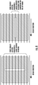
- FIG. 8 particularly illustrates various zones being equally-impacted (left image) and heavily impacting (right image).
- the controller 130 can determine a variance of the exposure area across the one or more zones, e.g. via an algorithm stored in the controller 130. Further, the controller 130 can minimize the variance of the exposure area across the zone(s) so as to equalize a power requirement across the build platform 118.
- the algorithm can be combined with other system algorithms that rank the packing and orientation from the recoater contact, build time productivity, etc., to provide a holistic ranking for the packing and orientation.
- the controller 130 may estimate the dosing plan for the powder of the PBF system 100 by receiving one or more inputs, e.g. relating to part geometry and a material type of the powder, calculating a shrinkage factor of the powder in a melted state, splitting the layers into a grid of pixels to determine which pixels require an amount of powder above a certain threshold and generating the dosing plan based on the shrink factor and the grid of pixels which may include an additional dosing factor to account for powder that may be lost to the areas surrounding the build box.
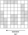
- FIG. 7 illustrates a simplified pixel diagram of one layer of the component in which certain pixels need more powder (as represented via shaded boxes) than others (as represented by white boxes).
- the dosing plan may be estimated by pre-determining a volume V of each layer of the component 108 (using the length 1, width w, and the thickness t), determining a perimeter P of each layer of the component 108, and estimating the powder dosing requirements of the dosing plan as a function of the volume V and the perimeter P.
- the method 100 may include updating the powder dosing requirements in real-time as a function of geometry of the component 108.
- the dosing plan may be estimated by adding an additional powder margin A ⁇ to the powder dosing requirements of the dosing plan.
- the additional powder margin A ⁇ may account for an area around and between the build platform 126 and the supply chamber 102 or the overflow collector 132 of the PBF system 100.
- the additional powder margin A ⁇ may account for melted powder having a lesser volume than powder particles.
- the method 200 may include determining at least one of a shrinkage factor or a compaction level for the powder based on a powder type and estimating the powder dosing requirements of the dosing plan as a function of the shrinkage factor and/or the compaction level.
- the method 200 may include providing the dosing plan to a controller of the PBF system 100. As shown at (206), the method 200 may include regulating the powder being supplied to the build chamber 106 of the PBF system 100 from the supply chamber 102 based on the dosing plan. In several embodiments, the method 200 may include automating, via the controller 130 of the PBF system 100, dosing level changes layer-by-layer. Referring still to FIG. 3 , as shown at (208), the method 200 may include additively manufacturing the component 108 onto the build platform 118 via the PBF system 100 using the powder 104 in the build chamber.
Landscapes
- Engineering & Computer Science (AREA)
- Chemical & Material Sciences (AREA)
- Materials Engineering (AREA)
- Manufacturing & Machinery (AREA)
- Physics & Mathematics (AREA)
- Optics & Photonics (AREA)
- Mechanical Engineering (AREA)
- Plasma & Fusion (AREA)
- Health & Medical Sciences (AREA)
- General Health & Medical Sciences (AREA)
- Toxicology (AREA)
- Analytical Chemistry (AREA)
- Automation & Control Theory (AREA)
- Powder Metallurgy (AREA)
Abstract
Description
- The present disclosure relates generally to additive manufacturing and more particularly to systems and methods for estimating powder dosing for additive manufacturing processes, such as direct metal laser melting (DMLM) systems.
- When fabricating a component using an additive manufacturing system such as a powder bed fusion (PBF) system, support structures may be utilized to anchor the component to a build platform and provide a thermally conductive pathway for heat to dissipate from the component. As examples, PBF systems include direct metal laser melting (DMLM) systems, electron beam melting (EBM) systems, selective laser melting (SLM) systems, directed metal laser sintering (DMLS) systems, and selective laser sintering (SLS) systems. These PBF systems involve focusing an energy beam onto a bed of powder to melt or sinter sequential layers of powder to one another to form a component.
- Typical PBF systems include a supply chamber, a build chamber, and an overflow collector. Thus, powder is provided in the supply chamber based on the component to be printed. The supply chamber also generally includes a piston which elevates a powder floor during operation of the system. As the floor elevates, a portion of the powder is forced out of the supply chamber and into the build chamber. A recoater, such as a roller or a blade, pushes some of the powder onto a build platform. The recoater sequentially distributes thin layers of powder onto the build platform. An energy source directs an energy beam such as a laser or an electron beam onto the thin layer of powder to melt or fuse the sequential layers of powder. Typically with a DMLM, EBM, or SLM system, the powder is fully melted, with respective layers being melted or re-melted with respective passes of the energy beam. Conversely, with DMLS, or SLS systems, layers of powder are sintered, fusing particles of powder with one another generally without reaching the melting point of the powder.
- For conventional PBF systems, the system does not regulate the powder being added to the build chamber. Further, in such systems, required powder dosing varies from layer to layer as a function of cross-sectional area, part perimeter, material properties, and laser scan parameters. Current methods for powder dosing, however, rely on user observation, and dosing regulation as the build progresses - for tall or complicated builds. However, high dosing of the powder produces waste in the overflow collector and can result in running out of powder before build is complete. In aviation applications, where the powder material is controlled and regulated, the wasted powder in the overflow collector cannot be reused. Alternatively, low dosing can result in short feeds, part defects, and/or build crashes. Accordingly, for conventional methods, overdosing is the preferred method to prevent short feeds.
- Accordingly, there exists a need for improved systems and methods for estimating powder dosing in additive manufacturing processes, such as DMLM systems, to eliminate waste and the need for manual operator intervention.
- Aspects and advantages will be set forth in part in the following description, or may be obvious from the description, or may be learned through practicing the presently disclosed subject matter.
- In one aspect, the present disclosure is directed to a method for forming a component, such as an aircraft component. The method includes estimating a dosing plan for powder of a powder bed fusion (PBF) system (such as a direct metal laser melting (DMLM) system) needed to form the component. The dosing plan includes powder dosing requirements needed per layer to form the component. The method includes providing the dosing plan to a controller of the PBF system. Further, the method includes regulating the powder being supplied to a build chamber of the PBF system from a supply chamber of the PBF system based on the dosing plan. In addition, the method includes additively manufacturing the component onto a build platform via the PBF system using the powder in the build chamber.
- In another aspect, the present disclosure is directed to a powder bed fusion (PBF) system for forming a component. The PBF system includes a build chamber having a build platform, a recoater, a supply chamber configured to receive an amount of powder based on the component to be formed, an energy source, and a controller. The supply chamber includes a supply platform, such that, as the supply platform elevates, the powder is forced out of the supply chamber layer-by-layer and into the build chamber atop the build platform via the recoater. The energy source includes an energy beam that is directed onto the powder in the build chamber to melt or fuse sequential layers of powder together to form the component. Further, the controller is configured to regulate the powder being supplied to the build chamber from the supply chamber of the PBF system based on a predetermined dosing plan stored therein, the dosing plan comprising powder dosing requirements needed per layer to form the component.
- These and other features, aspects and advantages will become better understood with reference to the following description and appended claims. The accompanying drawings, which are incorporated in and constitute a part of this specification, illustrate exemplary embodiments and, together with the description, serve to explain certain principles of the presently disclosed subject matter.
- A full and enabling disclosure, including the best mode thereof, directed to one of ordinary skill in the art, is set forth in the specification, which makes reference to the appended Figures, in which:
-
FIG. 1 illustrates a cross-sectional view of one embodiment of an additive manufacturing system according to the present disclosure; -
FIG. 2 illustrates a cross-sectional view of on embodiment of the additive manufacturing system ofFIG. 1 as the component is being built; -
FIG. 3 illustrates a block diagram of one embodiment of suitable components that may be included in a controller of an additive manufacturing system according to the present disclosure. -
FIG. 4 illustrates a flow chart of one embodiment of a method for additively manufacturing a component according to the present disclosure; -
FIG. 5 illustrates a perspective view of one embodiment of a layer of a component formed via additive manufacturing according to the present disclosure; -
FIG. 6 illustrates a perspective view of another embodiment of a layer of a component formed via additive manufacturing according to the present disclosure; -
FIG. 7 illustrates a perspective view of one embodiment of a pixelated layer of a component formed via additive manufacturing according to the present disclosure; and -
FIG. 8 illustrates a perspective view of one embodiment of a layer of a component formed via additive manufacturing according to the present disclosure. - Reference now will be made in detail to exemplary embodiments of the presently disclosed subject matter, one or more examples of which are illustrated in the drawings. Each example is provided by way of explanation and should not be interpreted as limiting the present disclosure. In fact, it will be apparent to those skilled in the art that various modifications and variations can be made in the present disclosure without departing from the scope of the present disclosure. For instance, features illustrated or described as part of one embodiment can be used with another embodiment to yield a still further embodiment. Thus, it is intended that the present disclosure covers such modifications and variations as come within the scope of the appended claims and their equivalents.
- It is understood that terms "upstream" and "downstream" refer to the relative direction with respect to fluid flow in a fluid pathway. For example, "upstream" refers to the direction from which the fluid flows, and "downstream" refers to the direction to which the fluid flows. It is also understood that terms such as "top", "bottom", "outward", "inward", and the like are words of convenience and are not to be construed as limiting terms. As used herein, the terms "first", "second", and "third" may be used interchangeably to distinguish one component from another and are not intended to signify location or importance of the individual components. The terms "a" and "an" do not denote a limitation of quantity, but rather denote the presence of at least one of the referenced item.
- Here and throughout the specification and claims, range limitations are combined and interchanged, and such ranges are identified and include all the sub-ranges contained therein unless context or language indicates otherwise. For example, all ranges disclosed herein are inclusive of the endpoints, and the endpoints are independently combinable with each other.
- Approximating language, as used herein throughout the specification and claims, is applied to modify any quantitative representation that could permissibly vary without resulting in a change in the basic function to which it is related. Accordingly, a value modified by a term or terms, such as "about", "approximately", and "substantially", are not to be limited to the precise value specified. In at least some instances, the approximating language may correspond to the precision of an instrument for measuring the value, or the precision of the methods or machines for constructing or manufacturing the components and/or systems.
- Generally, the present disclosure is directed to a method for estimating powder dosing/use needs on a layerwise basis for an additive manufacturing system and/or adjusting powder dosing layerwise based on that estimation. Accordingly, the present disclosure is more reliable than prior art systems that relied on user observation and dosing regulation as the build progresses. Thus, the methods of the preset disclosure can predict, reduce, and ultimately eliminate the need for manual operator intervention. As such, the powder required to build a particular part can be better managed, thereby extending the use of the powder and build height capability. Moreover, scrap builds (due to lack of powder to complete the build) are reduced and/or eliminated.
- Referring now to the drawings,
FIGS. 1 and 2 illustrate a schematic diagram of one embodiment of anadditive manufacturing system 100 according the present disclosure. Theadditive manufacturing system 100 may include, for example, a powder bed fusion (PBF) system, such as a direct metal laser melting (DMLM) system, an electron beam melting (EBM) system, a selective laser melting (SLM) system, a directed metal laser sintering (DMLS) system, or a selective laser sintering (SLS) system. As such, theadditive manufacturing system 100 builds components in a layer-by-layer manner by melting or fusing sequential layers of a powder material to one another. More specifically, in an embodiment, the illustratedadditive manufacturing system 100 includes apowder supply chamber 102 that contains a supply ofpowder material 104, and abuild chamber 106 within which acomponent 108 may be additively manufactured in a layer-by-layer manner. In certain embodiments, thecomponent 108 may be an aircraft component. For example, thecomponent 108 may be a component of a gas turbine engine. By way of further example, thecomponent 108 may be an airfoil separator or a heat exchanger for a gas turbine engine. In other embodiments, thecomponent 108 may be any suitable part that can benefit from additive manufacturing technology. - In additional embodiments, the
powder material 104 may include a metal or metal alloy, a plastic, a ceramic, and/or a composite. As examples, a metal or metal alloy powder may include tungsten, aluminum, chromium, copper, cobalt, molybdenum, tantalum, titanium, nickel, and steel, and combinations thereof, as well as super alloys, such as austenitic nickel-chromium-based super alloys. - The
powder supply chamber 102 includes apowder piston 110 that elevates apowder floor 112 during operation of thesystem 100. As thepowder floor 112 elevates, a portion of thepowder 104 is forced out of thepowder supply chamber 102. Arecoater 114 such as a roller or a blade pushes some of thepowder 104 across awork surface 116 and onto abuild platform 118. Therecoater 114 sequentially distributes thin layers ofpowder 104 onto thebuild platform 118. Anenergy source 120 directs anenergy beam 122 such as a laser or an electron beam onto the thin layer ofpowder 104 to melt or fuse the sequential layers ofpowder 104. Typically with a DMLM, EBM, or SLM system, thepowder 104 is fully melted, with respective layers being melted or re-melted with respective passes of theenergy beam 122. Conversely, with DMLS, or SLS systems, layers ofpowder 104 are sintered, fusing particles ofpowder 104 with one another generally without reaching the melting point of thepowder 104. - The
energy source 120 may be controlled via acontroller 130 for controlling the various components of thesystem 100. For example, ascanner 124 may be communicatively coupled with thecontroller 130 for controlling the path of the beam to melt or fuse only the portions of the layer ofpowder 104 that are to become part of thecomponent 108. The first layer or series of layers ofpowder 104 are typically melted or fused to thebuild platform 118, and then sequential layers ofpowder 104 are melted or fused to one another to additively manufacture thecomponent 108. The first several layers ofpowder 104 that become melted or fused to thebuild platform 118 define asupport structure 126 for thecomponent 108. As sequential layers ofpowder 104 are melted or fused to one another, as shown inFIG. 1 , abuild piston 128 gradually lowers thebuild platform 118 to make room for therecoater 114 to distribute sequential layers ofpowder 104. Sequential layers ofpowder 104 may be melted or fused to thecomponent 108 until a completedcomponent 108 has been fabricated (as shown inFIG. 2 ). - The
support structure 126 generally provides a surface to which sequential layers ofpowder 104 may be melted or fused, while holding the sequential layers of melted or fused powder in position while resisting residual stresses caused by rapid changes in temperature as theenergy beam 122 melts or fuses the sequential layers ofpowder 104. Thesupport structure 126 also provides a thermally conductive pathway to dissipate heat generated by theenergy beam 122. Typically, asupport structure 126 may be fabricated in the same manner as thecomponent 108. In some embodiments, thesame powder 104 may be used to fabricate thesupport structure 126 and thecomponent 108. Alternatively, in some embodiments, adifferent powder 104 may be used for thesupport structure 126 and thecomponent 108. When forming thesupport structure 126, theenergy beam 122 typically melts or sinters the top surface of thebuild platform 118 together with the first few layers ofpowder 104 to securely weld (e.g., melt or fuse) thesupport structure 126 to thebuild platform 118. After thecomponent 108 has been fabricated, thesupport structure 126 may be removed from thecomponent 108 in post-fabrication processes. - Still referring to
FIG. 1 , thePBF system 100 may also include anoverflow collector 132 for collecting excess powder from thebuild chamber 106. In such embodiments, therecoater 114 is moveable across thesupply chamber 102, thebuild chamber 106, and theoverflow collector 132 to move the excess powder to theoverflow collector 132. - The
controller 130 may be further configured to regulate thepowder 104 being supplied to thebuild chamber 106 from thesupply chamber 102 of thePBF system 100 based on a predetermined dosing plan stored therein, which will be discussed in more detail herein. As such, thecontroller 130 may be communicatively coupled to any of the components of thesystem 100 in order to control the operation of such components. As such, thecontroller 130 may include a computer or other suitable processing unit. Thus, in several embodiments, thecontroller 130 may include suitable computer-readable instructions that, when implemented, configure thecontroller 130 to perform various different functions, such as receiving, transmitting and/or executing control signals. - Referring now to
FIG. 3 , a block diagram of one embodiment of suitable components that may be included within thecontroller 130 is illustrated in accordance with aspects of the present subject matter. As shown, thecontroller 130 may include one or more processor(s) 134 and associated memory device(s) 136 configured to perform a variety of computer-implemented functions (e.g., performing the methods, steps, calculations and the like disclosed herein). As used herein, the term "processor" refers not only to integrated circuits referred to in the art as being included in a computer, but also refers to a controller, a microcontroller, a microcomputer, a programmable logic controller (PLC), an application specific integrated circuit, and other programmable circuits. Additionally, the memory device(s) 136 may generally comprise memory element(s) including, but are not limited to, computer readable medium (e.g., random access memory (RAM)), computer readable non-volatile medium (e.g., a flash memory), a floppy disk, a compact disc-read only memory (CD-ROM), a magneto-optical disk (MOD), a digital versatile disc (DVD) and/or other suitable memory elements. Additionally, thecontroller 130 may also include acommunications module 138 to facilitate communications between thecontroller 130 and the various components of thesystem 100. - For instance, the
communications module 138 may include a sensor interface 140 (e.g., one or more analog-to-digital converters) to permit the signals transmitted by one ormore sensors controller 130. It should be appreciated that thesensors communications module 138 using any suitable means. For example, as shown inFIG. 3 , thesensors sensor interface 138 via a wired connection. However, in other embodiments, thesensors processor 134 may be configured to receive one or more signals from thesensors - Referring now to
FIG. 4 , aflow chart 200 of a method for forming a component, such as an aircraft component, according to the present disclosure is illustrated. In general, themethod 200 will be described herein with reference to thecomponent 108 andadditive manufacturing system 100 ofFIGS. 1 and 2 . However, it should be appreciated that the disclosedmethod 200 may be implemented with additive manufacturing systems having any other suitable configurations. In addition, althoughFIG. 4 depicts steps performed in a particular order for purposes of illustration and discussion, the methods discussed herein are not limited to any particular order or arrangement. One skilled in the art, using the disclosures provided herein, will appreciate that various steps of the methods disclosed herein can be omitted, rearranged, combined, and/or adapted in various ways without deviating from the scope of the present disclosure. - As shown at (202), the
method 200 may include estimating a dosing plan for powder of the PBF system 100 (such as a DMLM system described herein) needed to form the component. For example, the dosing plan may include powder dosing requirements needed per layer to form the component. In certain embodiments, the powder dosing requirements may be predetermined. For example, in an embodiment, prior to building the component, thecontroller 130 may estimate the dosing plan for the powder of thePBF system 100 by dividing an exposure area of the component into one or more zones, as shown via the dotted lines inFIG. 8 . Such zone(s), as an example, may be associated with various parameters, such as a powder packing factor, a part orientation, a recoater contact, and/or build time productivity. For example,FIG. 8 particularly illustrates various zones being equally-impacted (left image) and heavily impacting (right image). Thus, thecontroller 130 can determine a variance of the exposure area across the one or more zones, e.g. via an algorithm stored in thecontroller 130. Further, thecontroller 130 can minimize the variance of the exposure area across the zone(s) so as to equalize a power requirement across thebuild platform 118. Moreover, the algorithm can be combined with other system algorithms that rank the packing and orientation from the recoater contact, build time productivity, etc., to provide a holistic ranking for the packing and orientation. - In another embodiment, as shown in
FIG. 7 for example, thecontroller 130 may estimate the dosing plan for the powder of thePBF system 100 by receiving one or more inputs, e.g. relating to part geometry and a material type of the powder, calculating a shrinkage factor of the powder in a melted state, splitting the layers into a grid of pixels to determine which pixels require an amount of powder above a certain threshold and generating the dosing plan based on the shrink factor and the grid of pixels which may include an additional dosing factor to account for powder that may be lost to the areas surrounding the build box. For example,FIG. 7 illustrates a simplified pixel diagram of one layer of the component in which certain pixels need more powder (as represented via shaded boxes) than others (as represented by white boxes). - In certain embodiments, as shown in
FIGS. 5 and 6 , for example, the dosing plan may be estimated by pre-determining a volume V of each layer of the component 108 (using thelength 1, width w, and the thickness t), determining a perimeter P of each layer of thecomponent 108, and estimating the powder dosing requirements of the dosing plan as a function of the volume V and the perimeter P. - In addition or in the alternative, the
method 100 may include updating the powder dosing requirements in real-time as a function of geometry of thecomponent 108. - More specifically, as shown in
FIG. 6 , the dosing plan may be estimated by adding an additional powder margin AΦ to the powder dosing requirements of the dosing plan. In such embodiments, the additional powder margin AΦ may account for an area around and between thebuild platform 126 and thesupply chamber 102 or theoverflow collector 132 of thePBF system 100. In addition or in the alternative, the additional powder margin AΦ may account for melted powder having a lesser volume than powder particles. - In another embodiment, the
method 200 may include determining at least one of a shrinkage factor or a compaction level for the powder based on a powder type and estimating the powder dosing requirements of the dosing plan as a function of the shrinkage factor and/or the compaction level. - Referring back to
FIG. 4 , as shown at (204), themethod 200 may include providing the dosing plan to a controller of thePBF system 100. As shown at (206), themethod 200 may include regulating the powder being supplied to thebuild chamber 106 of thePBF system 100 from thesupply chamber 102 based on the dosing plan. In several embodiments, themethod 200 may include automating, via thecontroller 130 of thePBF system 100, dosing level changes layer-by-layer. Referring still toFIG. 3 , as shown at (208), themethod 200 may include additively manufacturing thecomponent 108 onto thebuild platform 118 via thePBF system 100 using thepowder 104 in the build chamber. - Various aspects and embodiments of the present invention are defined by the following numbered clauses:
-
Clause 1. A method for forming a component, the method comprising: estimating a dosing plan for powder of a powder bed fusion (PBF) system needed to form the component, the dosing plan comprising powder dosing requirements needed per layer to form the component;
providing the dosing plan to a controller of the PBF system;
regulating the powder being supplied to a build chamber of the PBF system from a supply chamber of the PBF system based on the dosing plan; and
additively manufacturing the component onto a build platform via the PBF system using the powder in the build chamber. - Clause 2. The method of
clause 1, wherein estimating the dosing plan for the powder of the PBF system needed to form the component further comprises:- determining a volume of each layer of the component;
- determining a perimeter of each layer of the component; and
- estimating the powder dosing requirements of the dosing plan as a function of the volume and the perimeter.
- Clause 3. The method of clauses 1-2, further comprising:
- determining at least one of a shrinkage factor or a compaction level for the powder based on a powder type; and
- estimating the powder dosing requirements of the dosing plan as a function of at least one of the shrinkage factor or the compaction level.
- Clause 4. The method of any of the preceding clauses, wherein estimating the dosing plan for powder of the PBF system further comprises:
- dividing an exposure area of the component into one or more zones, the one or more zones being associated with one or more of a powder packing factor, a part orientation, a recoater contact, or build time productivity;
- determining, via an algorithm stored in the controller of the PBF system a variance of the exposure area across the one or more zones; and
- minimizing the variance of the exposure area across the one or more zones so as to equalize a power requirement across the build platform.
- Clause 5. The method of any of the preceding clauses, wherein estimating the dosing plan for powder of the PBF system further comprises:
- receiving, via the controller, one or more inputs relating to slice files and a material type of the powder;
- calculating, via the controller, a shrinkage factor of the powder in a melted state;
- splitting, via the controller, the one or more slice files into a grid of pixels to determine which pixels require an amount of powder above a certain threshold;
- generating, via the controller, the dosing plan based on the shrink factor and the grid of pixels.
- Clause 6. The method of any of the preceding clauses, wherein estimating the dosing plan for the powder of the PBF system needed to form the component further comprises:
adding an additional powder margin to the powder dosing requirements of the dosing plan to account for an area between the build platform and at least one of the supply chamber or an overflow collector of the PBF system. - Clause 7. The method of any of the preceding clauses, wherein estimating the dosing plan for the powder of the PBF system needed to form the component further comprises:
adding an additional powder margin to the powder dosing requirements of the dosing plan to account for melted powder having a lesser volume than powder particles. - Clause 8. The method of any of the preceding clauses, further comprising automating, via the controller of the PBF system, dosing level changes layer-by-layer.
- Clause 9. The method of any of the preceding clauses, wherein the PBF system comprises a direct metal laser melting (DMLM) system.
- Clause 10. The method of any of the preceding clauses, wherein the component is an aircraft component.
- Clause 11. A powder bed fusion (PBF) system for forming a component, the PBF system comprising:
- a build chamber comprising a build platform;
- a recoater;
- a supply chamber configured to receive an amount of powder based on the component to be formed, the supply chamber comprising a supply platform, wherein, as the supply platform elevates, the powder is forced out of the supply chamber layer-by-layer and into the build chamber atop the build platform via the recoater;
- an energy source comprising an energy beam that is directed onto the powder in the build chamber to melt or fuse sequential layers of powder together to form the component; and
- a controller for estimating a dosing plan for the powder needed to form the component and regulating the powder being supplied to the build chamber from the supply chamber of the PBF system based on the dosing plan, the dosing plan comprising powder dosing requirements needed per layer to form the component.
- Clause 12. The PBF system of clause 11, further comprising an overflow collector for collecting excess powder from the build chamber, the recoater moveable across the supply chamber, the build chamber, and the overflow collector to move the excess powder to the overflow collector.
- Clause 13. The PBF system of clauses 11-12, wherein the energy beam comprises at least one of a laser or an electron beam.
- Clause 14. The PBF system of clauses 11-13, wherein estimating the dosing plan for the powder needed to form the component further comprises: determining a perimeter of each layer of the component; and
estimating the powder dosing requirements of the dosing plan as a function of the volume and the perimeter. - Clause 15. The PBF system of clauses 11-14, wherein the controller is further configured to:
- determine at least one of a shrinkage factor or a compaction level for the powder based on a powder type; and
- estimate the powder dosing requirements of the dosing plan as a function of at least one of the shrinkage factor or the compaction level.
- Clause 16. The PBF system of clauses 11-15, wherein estimating the dosing plan for powder of the PBF system further comprises:
- dividing an exposure area of the component into one or more zones, the one or more zones being associated with one or more of a powder packing factor, a part orientation, a recoater contact, or build time productivity;
- determining, via an algorithm stored in the controller of the PBF system a variance of the exposure area across the one or more zones; and
- minimizing the variance of the exposure area across the one or more zones so as to equalize a power requirement across the build platform.
- Clause 17. The PBF system of clauses 11-16, wherein estimating the dosing plan for powder of the PBF system further comprises:
- receiving, via the controller, one or more inputs relating to slice files and a material type of the powder;
- calculating, via the controller, a shrinkage factor of the powder in a melted state;
- splitting, via the controller, the one or more slice files into a grid of pixels to determine which pixels require an amount of powder above a certain threshold; generating, via the controller, the dosing plan based on the shrink factor and the grid of pixels.
- Clause 18. The PBF system of clauses 11-17, wherein the controller is further configured to estimate the dosing plan for the powder of the PBF system needed to form the component by:
adding an additional powder margin to the powder dosing requirements of the dosing plan to account for an area between the build platform and at least one of the supply chamber or an overflow collector of the PBF system. - Clause 19. The PBF system of clauses 11-18, wherein the controller is further configured to estimate the dosing plan for the powder of the PBF system needed to form the component by:
adding an additional powder margin to the powder dosing requirements of the dosing plan to account for melted powder having a lesser volume than powder particles. - Clause 20. The PBF system of clauses 11-19, wherein the controller of the PBF system automates dosing level changes layer-by-layer.
- This written description uses exemplary embodiments to describe the presently disclosed subject matter, including the best mode, and also to enable any person skilled in the art to practice such subject matter, including making and using any devices or systems and performing any incorporated methods. The patentable scope of the presently disclosed subject matter is defined by the claims, and may include other examples that occur to those skilled in the art. Such other examples are intended to be within the scope of the claims if they include structural elements that do not differ from the literal language of the claims, or if they include equivalent structural elements with insubstantial differences from the literal languages of the claims.
Claims (15)
- A method (100) for forming a component (108), the method (100) comprising:estimating a dosing plan for powder (104) of a powder (104) bed fusion (PBF) system (100) needed to form the component (108), the dosing plan comprising powder (104) dosing requirements needed per layer (146) to form the component (108);providing the dosing plan to a controller (130) of the PBF system (100);regulating the powder (104) being supplied to a build chamber (106) of the PBF system (100) from a supply chamber (102) of the PBF system (100) based on the dosing plan; andadditively manufacturing the component (108) via the PBF system (100) using the powder (104).
- The method (100) of Claim 1, wherein estimating the dosing plan for the powder (104) of the PBF system (100) needed to form the component (108) further comprises:determining a volume of each layer (146) of the component (108);determining a perimeter of each layer (146) of the component (108); andestimating the powder (104) dosing requirements of the dosing plan as a function of the volume and the perimeter.
- The method (100) of Claim 2, further comprising:determining at least one of a shrinkage factor or a compaction level for the powder (104) based on a powder (104) type; andestimating the powder (104) dosing requirements of the dosing plan as a function of at least one of the shrinkage factor or the compaction level.
- The method (100) of any one of Claims 1-3, wherein estimating the dosing plan for the powder (104) of the PBF system (100) needed to form the component (108) further comprises:
adding an additional powder (104) margin to the powder (104) dosing requirements of the dosing plan to account for an area between the build platform (118) and at least one of the supply chamber (102) or an overflow collector (132) of the PBF system (100). - The method (100) of any one of Claims 1-4, wherein estimating the dosing plan for the powder (104) of the PBF system (100) needed to form the component (108) further comprises:
adding an additional powder (104) margin to the powder (104) dosing requirements of the dosing plan to account for melted powder (104) having a lesser volume than powder (104) particles. - The method (100) of any one of Claims 1-5, further comprising automating, via the controller (130) of the PBF system (100), dosing level changes layer (146)-by-layer (146).
- A powder (104) bed fusion (PBF) system (100) for forming a component (108), the PBF system (100) comprising:a build chamber (106) comprising a build platform (118);a recoater (114);a supply chamber (102) configured to receive an amount of powder (104) based on the component (108) to be formed, the supply chamber (102) comprising a supply platform, wherein, as the supply platform elevates, the powder (104) is forced out of the supply chamber (102) layer (146)-by-layer (146) and into the build chamber (106) atop the build platform (118) via the recoater (114);an energy source (120) comprising an energy beam (122) that is directed onto the powder (104) in the build chamber (106) to melt or fuse sequential layers of powder (104) together to form the component (108); anda controller (130) for regulating the powder (104) being supplied to the build chamber (106) from the supply chamber (102) of the PBF system (100) based on a predetermined dosing plan stored therein, the dosing plan comprising powder (104) dosing requirements needed per layer (146) to form the component (108).
- The PBF system (100) of Claim 7, further comprising an overflow collector (132) for collecting excess powder (104) from the build chamber (106), the recoater (114) moveable across the supply chamber (102), the build chamber (106), and the overflow collector (132) so as to move the excess powder (104) to the overflow collector (132).
- The PBF system (100) of Claim 7 or Claim 8, wherein the energy beam (122) comprises at least one of a laser or an electron beam.
- The PBF system (100) of any one of Claims 7-9, wherein estimating the dosing plan for the powder (104) of the PBF system (100) needed to form the component (108) further comprises:determining a volume of each layer (146) of the component (108);determining a perimeter of each layer (146) of the component (108); andestimating the powder (104) dosing requirements of the dosing plan as a function of the volume and the perimeter.
- The PBF system (100) of Claim 10, further comprising:determining at least one of a shrinkage factor or a compaction level for the powder (104) based on a powder (104) type; andestimating the powder (104) dosing requirements of the dosing plan as a function of at least one of the shrinkage factor or the compaction level.
- The PBF system (100) of any one of Claims 7-11, wherein estimating the dosing plan for the powder (104) of the PBF system (100) needed to form the component (108) further comprises:
adding an additional powder (104) margin to the powder (104) dosing requirements of the dosing plan to account for an area between the build platform (118) and at least one of the supply chamber (102) or an overflow collector (132) of the PBF system (100). - The PBF system (100) of any one of Claims 7-12, wherein estimating the dosing plan for the powder (104) of the PBF system (100) needed to form the component (108) further comprises:
adding an additional powder (104) margin to the powder (104) dosing requirements of the dosing plan to account for melted powder (104) having a lesser volume than powder (104) particles. - The PBF system (100) of any one of Claims 7-13, wherein the controller (130) of the PBF system (100) automates dosing level changes layer (146)-by-layer (146).
- The PBF system (100) of any one of Claims 7-14, wherein the PBF system (100) comprises a direct metal laser melting (DMLM) system (100).
Applications Claiming Priority (1)
| Application Number | Priority Date | Filing Date | Title |
|---|---|---|---|
| US17/011,325 US11638959B2 (en) | 2020-09-03 | 2020-09-03 | Systems and methods for estimating powder dosing in additive manufacturing processes |
Publications (1)
| Publication Number | Publication Date |
|---|---|
| EP3964309A1 true EP3964309A1 (en) | 2022-03-09 |
Family
ID=77274754
Family Applications (1)
| Application Number | Title | Priority Date | Filing Date |
|---|---|---|---|
| EP21190607.8A Pending EP3964309A1 (en) | 2020-09-03 | 2021-08-10 | Systems and methods for estimating powder dosing in additive manufacturing processes |
Country Status (4)
| Country | Link |
|---|---|
| US (2) | US11638959B2 (en) |
| EP (1) | EP3964309A1 (en) |
| JP (1) | JP7252290B2 (en) |
| CN (1) | CN114131041B (en) |
Citations (3)
| Publication number | Priority date | Publication date | Assignee | Title |
|---|---|---|---|---|
| DE102015223719A1 (en) * | 2015-11-30 | 2017-06-01 | Eos Gmbh Electro Optical Systems | Method and device for building material requirement determination |
| US10414149B2 (en) * | 2016-10-21 | 2019-09-17 | Microsoft Technology Licensing, Llc | Material estimate for fabrication of three-dimensional object |
| US20200269510A1 (en) * | 2015-12-23 | 2020-08-27 | Addup | Additive manufacturing process comprising a powder distribution step performed by an injector |
Family Cites Families (31)
| Publication number | Priority date | Publication date | Assignee | Title |
|---|---|---|---|---|
| GB2378150A (en) | 2001-07-31 | 2003-02-05 | Dtm Corp | Fabricating a three-dimensional article from powder |
| US7045738B1 (en) | 2002-10-01 | 2006-05-16 | Southern Methodist University | Powder delivery system and method |
| FR2876303B1 (en) | 2004-10-08 | 2007-01-05 | Sames Technologies Soc Par Act | DEVICE FOR DOSING AND CONTINUOUS TRANSPORTING PULVERULENT PRODUCT, USE OF SUCH A DEVICE AND PROJECTING DEVICE FOR PROJECTING PRODUCT COMPRISING SUCH A DEVICE |
| US8818544B2 (en) | 2011-09-13 | 2014-08-26 | Stratasys, Inc. | Solid identification grid engine for calculating support material volumes, and methods of use |
| CN104780872B (en) * | 2012-09-21 | 2017-04-05 | 康复米斯公司 | The method and system of the design and manufacture of optimization implant component is manufactured using free entity |
| GB201404854D0 (en) * | 2014-03-18 | 2014-04-30 | Renishaw Plc | Selective solidification apparatus and method |
| WO2015152875A1 (en) * | 2014-03-31 | 2015-10-08 | Hewlett-Packard Development Company, L.P. | Generating three-dimensional objects |
| EP3245045A4 (en) * | 2015-01-13 | 2018-10-31 | Sigma Labs, Inc. | Material qualification system and methodology |
| JP6458543B2 (en) | 2015-02-23 | 2019-01-30 | 株式会社リコー | Modeling data creation device, program, modeling device |
| DE102015213106A1 (en) * | 2015-07-13 | 2017-01-19 | Eos Gmbh Electro Optical Systems | Method and apparatus for building material metering in a generative manufacturing process |
| WO2017019046A1 (en) | 2015-07-28 | 2017-02-02 | Hewlett-Packard Development Company, L.P. | Three-dimensional object property determination |
| EP3349972A4 (en) * | 2015-09-16 | 2019-05-22 | Applied Materials, Inc. | BASE PLATE MANUFACTURE, ENCLOSURE MANUFACTURE, AND MANUFACTURE OF SUPPORT MOUNTS IN ADDITIVE MANUFACTURE |
| EP4137256A1 (en) * | 2015-10-30 | 2023-02-22 | Seurat Technologies, Inc. | Additive manufacturing system and method |
| US20170165910A1 (en) * | 2015-12-11 | 2017-06-15 | Honeywell Federal Manufacturing & Technologies, Llc | Multi-material dispensing for improved process efficiency in powder bed additive manufacturing |
| WO2018110838A1 (en) | 2016-12-12 | 2018-06-21 | 3D Systems Korea, Inc. | Apparatus and method for estimating material usage amount and printing time for three-dimensional printer |
| EP3579963A4 (en) * | 2017-02-07 | 2020-12-16 | Valorbec Societe en Commandite | METHODS AND SYSTEMS FOR GENERATIVE MANUFACTURING |
| WO2018154283A1 (en) * | 2017-02-21 | 2018-08-30 | Renishaw Plc | Powder bed fusion apparatus and break-out device |
| US20180311757A1 (en) * | 2017-04-28 | 2018-11-01 | Divergent Technologies, Inc. | Additive manufacturing control systems |
| US20190070787A1 (en) | 2017-08-10 | 2019-03-07 | William Marsh Rice University | Machine learning enabled model for predicting the spreading process in powder-bed three-dimensional printing |
| TWI781232B (en) | 2017-10-10 | 2022-10-21 | 美商應用材料股份有限公司 | Dispensing system and method of dispensing powder in additive manufacturing apparatus |
| EP3695922B1 (en) * | 2017-10-13 | 2024-04-24 | IHI Corporation | Additive manufacturing device comprising a powder feeding device |
| EP3473360B1 (en) * | 2017-10-23 | 2022-08-10 | Renishaw PLC | Powder bed fusion apparatus |
| EP3521027B1 (en) | 2018-01-31 | 2020-10-07 | CL Schutzrechtsverwaltungs GmbH | Method for determining an amount of build material which is to be applied in a build plane and dosing device comprising a control unit using the method |
| US11383424B2 (en) * | 2018-04-25 | 2022-07-12 | General Electric Company | System and method for thermoforming an object |
| US10744599B2 (en) | 2018-07-30 | 2020-08-18 | Mitsubishi Electric Corporation | Metal additive manufacturing welding condition control device and method |
| EP3829799A1 (en) * | 2018-08-03 | 2021-06-09 | Renishaw PLC | Powder bed fusion apparatus and methods |
| WO2020028979A1 (en) * | 2018-08-06 | 2020-02-13 | Edinger Ralf | Apparatus and method for dispensing powdered material |
| US11458681B2 (en) * | 2019-01-30 | 2022-10-04 | General Electric Company | Recoating assembly for an additive manufacturing machine |
| US11396046B2 (en) * | 2019-02-12 | 2022-07-26 | General Electric Company | Methods for additively manufacturing components with reduced build failures caused by temperature variations |
| CN110560691B (en) * | 2019-10-17 | 2021-01-12 | 江苏科技大学 | Estimation method for powder consumption in powder bed melting additive manufacturing |
| US11537111B2 (en) * | 2020-04-01 | 2022-12-27 | General Electric Company | Methods and apparatus for 2-D and 3-D scanning path visualization |
-
2020
- 2020-09-03 US US17/011,325 patent/US11638959B2/en active Active
-
2021
- 2021-08-10 EP EP21190607.8A patent/EP3964309A1/en active Pending
- 2021-09-02 JP JP2021143446A patent/JP7252290B2/en active Active
- 2021-09-03 CN CN202111035361.6A patent/CN114131041B/en active Active
-
2023
- 2023-03-30 US US18/193,198 patent/US12059726B2/en active Active
Patent Citations (4)
| Publication number | Priority date | Publication date | Assignee | Title |
|---|---|---|---|---|
| DE102015223719A1 (en) * | 2015-11-30 | 2017-06-01 | Eos Gmbh Electro Optical Systems | Method and device for building material requirement determination |
| US20200247059A1 (en) * | 2015-11-30 | 2020-08-06 | Eos Gmbh Electro Optical Systems | Method and Device for Ascertaining Required Construction Material |
| US20200269510A1 (en) * | 2015-12-23 | 2020-08-27 | Addup | Additive manufacturing process comprising a powder distribution step performed by an injector |
| US10414149B2 (en) * | 2016-10-21 | 2019-09-17 | Microsoft Technology Licensing, Llc | Material estimate for fabrication of three-dimensional object |
Non-Patent Citations (1)
| Title |
|---|
| "Additive Manufacturing of Metals: The Technology, Materials, Design and Production", 13 May 2017, SPRINGER INTERNATIONAL PUBLISHING, ISBN: 978-3-319-55128-9, article L. YANG: "Ch. 2 - Additive Manufacturing Process Chain", pages: 33 - 43, XP055506460, DOI: 10.1007/978-3-319-55128-9_2 * |
Also Published As
| Publication number | Publication date |
|---|---|
| US11638959B2 (en) | 2023-05-02 |
| US12059726B2 (en) | 2024-08-13 |
| CN114131041B (en) | 2024-06-25 |
| US20230256511A1 (en) | 2023-08-17 |
| JP7252290B2 (en) | 2023-04-04 |
| JP2022043011A (en) | 2022-03-15 |
| CN114131041A (en) | 2022-03-04 |
| US20220062989A1 (en) | 2022-03-03 |
Similar Documents
| Publication | Publication Date | Title |
|---|---|---|
| US9718129B2 (en) | Additive manufacturing method and apparatus | |
| EP3135408B1 (en) | Powder-bed additive manufacturing device and method | |
| US20190054567A1 (en) | Additive manufacturing systems, additive manufactured components including portions having distinct porosities, and methods of forming same | |
| US20180029306A1 (en) | Methods and ghost supports for additive manufacturing | |
| EP3695923B1 (en) | Methods for additively manufacturing components with reduced build failures caused by temperature variations | |
| US10744562B2 (en) | Additive manufacturing employing a plurality of electron beam sources | |
| JP2017185804A (en) | Apparatus and method for selective laser sintering of objects having voids | |
| EP3178588A2 (en) | Adjusting process parameters of an additive mahufacturing process to reduce conglomerated powder in cavity | |
| CN105562688A (en) | Manufacture of a component through selective laser melting | |
| US10695867B2 (en) | Controlling microstructure of selected range of layers of object during additive manufacture | |
| CN110545940B (en) | Method for manufacturing workpiece, method for establishing correction parameter and storage medium | |
| US20180250743A1 (en) | Triangle hatch pattern for additive manufacturing | |
| US20190054568A1 (en) | Additive manufactured components including sacrifical caps and methods of forming same | |
| US12059726B2 (en) | Systems and methods for estimating powder dosing in additive manufacturing processes | |
| WO2022117326A1 (en) | Fusing one or more cross sections by electron beam powder bed fusion | |
| EP3315227A1 (en) | Method of manufacturing metal articles | |
| McNeil et al. | Framework for CAD to part of large scale additive manufacturing of metal (LSAMM) in arbitrary directions | |
| US11351612B2 (en) | Manufacturing support and method for additive manufacturing process | |
| US10589353B2 (en) | Datum structure for additively manufactured object removal from build platform | |
| JP2025067897A (en) | Additive Manufacturing Process | |
| EP2757429A1 (en) | Object production |
Legal Events
| Date | Code | Title | Description |
|---|---|---|---|
| PUAI | Public reference made under article 153(3) epc to a published international application that has entered the european phase |
Free format text: ORIGINAL CODE: 0009012 |
|
| STAA | Information on the status of an ep patent application or granted ep patent |
Free format text: STATUS: THE APPLICATION HAS BEEN PUBLISHED |
|
| AK | Designated contracting states |
Kind code of ref document: A1 Designated state(s): AL AT BE BG CH CY CZ DE DK EE ES FI FR GB GR HR HU IE IS IT LI LT LU LV MC MK MT NL NO PL PT RO RS SE SI SK SM TR |
|
| STAA | Information on the status of an ep patent application or granted ep patent |
Free format text: STATUS: REQUEST FOR EXAMINATION WAS MADE |
|
| 17P | Request for examination filed |
Effective date: 20220830 |
|
| RBV | Designated contracting states (corrected) |
Designated state(s): AL AT BE BG CH CY CZ DE DK EE ES FI FR GB GR HR HU IE IS IT LI LT LU LV MC MK MT NL NO PL PT RO RS SE SI SK SM TR |
|
| STAA | Information on the status of an ep patent application or granted ep patent |
Free format text: STATUS: EXAMINATION IS IN PROGRESS |
|
| 17Q | First examination report despatched |
Effective date: 20231010 |