EP3964240A1 - Methods and systems for uv-based aircraft decontamination - Google Patents
Methods and systems for uv-based aircraft decontamination Download PDFInfo
- Publication number
- EP3964240A1 EP3964240A1 EP21181687.1A EP21181687A EP3964240A1 EP 3964240 A1 EP3964240 A1 EP 3964240A1 EP 21181687 A EP21181687 A EP 21181687A EP 3964240 A1 EP3964240 A1 EP 3964240A1
- Authority
- EP
- European Patent Office
- Prior art keywords
- transparent
- transparent surface
- light beams
- nanometers
- decontamination
- Prior art date
- Legal status (The legal status is an assumption and is not a legal conclusion. Google has not performed a legal analysis and makes no representation as to the accuracy of the status listed.)
- Granted
Links
Images



Classifications
-
- A—HUMAN NECESSITIES
- A61—MEDICAL OR VETERINARY SCIENCE; HYGIENE
- A61L—METHODS OR APPARATUS FOR STERILISING MATERIALS OR OBJECTS IN GENERAL; DISINFECTION, STERILISATION OR DEODORISATION OF AIR; CHEMICAL ASPECTS OF BANDAGES, DRESSINGS, ABSORBENT PADS OR SURGICAL ARTICLES; MATERIALS FOR BANDAGES, DRESSINGS, ABSORBENT PADS OR SURGICAL ARTICLES
- A61L2/00—Disinfection or sterilisation of materials or objects, in general; Accessories therefor
- A61L2/02—Disinfection or sterilisation of materials or objects, in general; Accessories therefor using physical processes
- A61L2/08—Radiation
- A61L2/10—Ultraviolet [UV] radiation
-
- A—HUMAN NECESSITIES
- A61—MEDICAL OR VETERINARY SCIENCE; HYGIENE
- A61L—METHODS OR APPARATUS FOR STERILISING MATERIALS OR OBJECTS IN GENERAL; DISINFECTION, STERILISATION OR DEODORISATION OF AIR; CHEMICAL ASPECTS OF BANDAGES, DRESSINGS, ABSORBENT PADS OR SURGICAL ARTICLES; MATERIALS FOR BANDAGES, DRESSINGS, ABSORBENT PADS OR SURGICAL ARTICLES
- A61L2/00—Disinfection or sterilisation of materials or objects, in general; Accessories therefor
- A61L2/26—Accessories
-
- B—PERFORMING OPERATIONS; TRANSPORTING
- B64—AIRCRAFT; AVIATION; COSMONAUTICS
- B64D—EQUIPMENT FOR FITTING IN OR TO AIRCRAFT; FLIGHT SUITS; PARACHUTES; ARRANGEMENT OR MOUNTING OF POWER PLANTS OR PROPULSION TRANSMISSIONS IN AIRCRAFT
- B64D11/00—Passenger or crew accommodation; Flight-deck installations not otherwise provided for
-
- B—PERFORMING OPERATIONS; TRANSPORTING
- B64—AIRCRAFT; AVIATION; COSMONAUTICS
- B64D—EQUIPMENT FOR FITTING IN OR TO AIRCRAFT; FLIGHT SUITS; PARACHUTES; ARRANGEMENT OR MOUNTING OF POWER PLANTS OR PROPULSION TRANSMISSIONS IN AIRCRAFT
- B64D11/00—Passenger or crew accommodation; Flight-deck installations not otherwise provided for
- B64D11/02—Toilet fittings
-
- B—PERFORMING OPERATIONS; TRANSPORTING
- B64—AIRCRAFT; AVIATION; COSMONAUTICS
- B64D—EQUIPMENT FOR FITTING IN OR TO AIRCRAFT; FLIGHT SUITS; PARACHUTES; ARRANGEMENT OR MOUNTING OF POWER PLANTS OR PROPULSION TRANSMISSIONS IN AIRCRAFT
- B64D11/00—Passenger or crew accommodation; Flight-deck installations not otherwise provided for
- B64D11/04—Galleys
-
- E—FIXED CONSTRUCTIONS
- E05—LOCKS; KEYS; WINDOW OR DOOR FITTINGS; SAFES
- E05B—LOCKS; ACCESSORIES THEREFOR; HANDCUFFS
- E05B1/00—Knobs or handles for wings; Knobs, handles, or press buttons for locks or latches on wings
- E05B1/0069—Sanitary doorknobs or handles, e.g. comprising a disinfectant
-
- A—HUMAN NECESSITIES
- A61—MEDICAL OR VETERINARY SCIENCE; HYGIENE
- A61L—METHODS OR APPARATUS FOR STERILISING MATERIALS OR OBJECTS IN GENERAL; DISINFECTION, STERILISATION OR DEODORISATION OF AIR; CHEMICAL ASPECTS OF BANDAGES, DRESSINGS, ABSORBENT PADS OR SURGICAL ARTICLES; MATERIALS FOR BANDAGES, DRESSINGS, ABSORBENT PADS OR SURGICAL ARTICLES
- A61L2103/00—Materials or objects being the target of disinfection or sterilisation
- A61L2103/75—Room floors or walls
-
- A—HUMAN NECESSITIES
- A61—MEDICAL OR VETERINARY SCIENCE; HYGIENE
- A61L—METHODS OR APPARATUS FOR STERILISING MATERIALS OR OBJECTS IN GENERAL; DISINFECTION, STERILISATION OR DEODORISATION OF AIR; CHEMICAL ASPECTS OF BANDAGES, DRESSINGS, ABSORBENT PADS OR SURGICAL ARTICLES; MATERIALS FOR BANDAGES, DRESSINGS, ABSORBENT PADS OR SURGICAL ARTICLES
- A61L2202/00—Aspects relating to methods or apparatus for disinfecting or sterilising materials or objects
- A61L2202/10—Apparatus features
- A61L2202/11—Apparatus for generating biocidal substances, e.g. vaporisers, UV lamps
-
- A—HUMAN NECESSITIES
- A61—MEDICAL OR VETERINARY SCIENCE; HYGIENE
- A61L—METHODS OR APPARATUS FOR STERILISING MATERIALS OR OBJECTS IN GENERAL; DISINFECTION, STERILISATION OR DEODORISATION OF AIR; CHEMICAL ASPECTS OF BANDAGES, DRESSINGS, ABSORBENT PADS OR SURGICAL ARTICLES; MATERIALS FOR BANDAGES, DRESSINGS, ABSORBENT PADS OR SURGICAL ARTICLES
- A61L2202/00—Aspects relating to methods or apparatus for disinfecting or sterilising materials or objects
- A61L2202/10—Apparatus features
- A61L2202/14—Means for controlling sterilisation processes, data processing, presentation and storage means, e.g. sensors, controllers, programs
Definitions
- a door handle and other like components may be covered with various contaminants, such as viruses, bacteria, and other like pathogens or microbial contaminants.
- a conventional approach involves flight attendants periodically cleaning such surfaces. Furthermore, ground-based cleaning personnel conduct comprehensive decontamination between flights. However, there may not be sufficient time to effectively clean each touch surface, e.g., between two consecutive uses. Moreover, individual flight attendants may not thoroughly clean each surface or miss some surfaces. As such, various contaminants may remain on particular surfaces which may pose real and/or perceived health concerns to future passengers.
- Described herein are methods and systems for decontaminating surfaces on aircraft from pathogens using UV lights with wavelengths between about 200 nanometers and about 240 nanometers. These wavelengths are able to effectively decontaminate pathogens while remaining safe to humans. In other words, humans can remain in decontamination zones during operation of these systems.
- UV transparent apparatuses such as door, cabinet and other handles, allow decontamination of all surfaces of these apparatuses whether these surfaces are directly or indirectly exposed to the UV light. The indirect exposure is provided by the UV lights passing through the transparent apparatus. Therefore, even surfaces without a line of sight to UV light sources are decontaminated. As such, these methods and systems allow to achieve effective decontamination of an apparatus with a complex surface (e.g., a door, cabinet or otherhandle) without requiring many UV light sources positioned around this apparatus.
- a complex surface e.g., a door, cabinet or otherhandle
- FIG. 1 is a schematic illustration of aircraft 100, comprising lavatories 102 and galley kitchen 104, in accordance with some examples.
- Each of these facilities is used by multiple different people. For example, each lavatory may be used dozens of time during each flight, especially during long intercontinental flights.
- each of these facilities comprises multiple surfaces, which may be contaminated via a direct contact (e.g., touch) or an indirect contact (e.g., sneezing, coughing). Some of these surfaces have complex geometries, which makes the decontamination process even more challenging.
- Methods (described below with reference to FIG. 5 ) and systems (described below with reference to FIGS. 2A, 2B , and 2C ) are configured to decontaminate any complex surfaces on aircraft from pathogens using UV lights with wavelengths between about 200 nanometers and about 240 nanometers, such as about 222 nanometers or about 207 nanometers. As noted above, these wavelengths are able to effectively decontaminate pathogens while remaining safe to humans. In other words, humans can remain in decontamination zones during operation of these systems.
- this UV subrange is absorbed by the DNA and RNA of microorganisms, which causes changes in the DNA and RNA structure of these microorganisms. These changes render the microorganisms incapable of replicating, which effectively controls the spread. More specifically, these microorganisms are unable to multiply to infectious numbers within a host, such as a human. While conventional approaches focus on a peak of the germicidal effectiveness curve, which corresponds to about 265 nanometer radiation, this wavelength is harmful to humans. As such, these conventional approaches cannot be used while passengers or flight crews are present in areas, requiring decontamination.
- a conventional disinfection cycle lasts about 10-30 minutes, which imposes unreasonable requirements of taking aircraft facilities offline during such a disinfection cycle.
- conventional approaches are limited to the "line-of-sight" aspect, only irradiating and decontaminating surfaces within a direct line of sight of a UV light source. Surfaces can be blocked from the light if objects are other objects on the way. Furthermore, non-transparent objects have shadow sides, which can still be contaminated and remain contaminated during these conventional decontamination methods.
- aircraft 100 comprises decontamination systems 110 positioned in each of lavatories 102 and galley kitchen 104.
- Each facility with a risk of pathogen contamination may be designated as a decontamination area and decontamination system 110 is positioned in this area.
- Decontamination systems 110 rely on a combination of a specific UV subrange (of between about 200 nanometers and about 240 nanometers) and use of UV transparent apparatuses, such as door handles.
- the UV transparent apparatuses described herein allow decontamination of all surfaces of these apparatuses whether these surfaces are directly or indirectly exposed to the UV light.
- the indirect exposure is provided by the UV lights passing through the apparatus.
- a UV transparent apparatus comprises or is formed entirely from a quartz glass, such as Corning HPFS ® Fused Silica 7980.
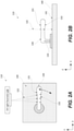
- FIG. 2A is a schematic side view of decontamination system 110 for decontaminating surfaces on aircraft 100 from pathogens, in accordance with some examples.
- Decontamination system 110 comprises one or more UV light sources 120 and one of more UV transparent apparatuses 130. While FIG. 2A illustrates one UV light source 120 and one UV transparent apparatus 130, one having ordinary skill in the art would understand that decontamination system 110 may comprise any number of UV light sources 120 and UV transparent apparatuses 130.
- one UV light source 120 may be used for decontaminating multiple UV transparent apparatuses 130, such that all of these UV transparent apparatuses 130 are within a line of sight of this one UV light source 120.
- multiple UV light source 120 may be used for decontaminating one UV transparent apparatus 130.
- multiple UV light source 120 may be used for decontaminating multiple UV transparent apparatuses 130.
- UV light source 120 is configured to generate UV light beam 122 with a wavelength of between about 200 nanometers and about 240 nanometers, or about 200 to about 222 nm, or from about 207 to about 222 nm.
- wavelengths of 200-240 nanometers represent a rather small subrange of a shortwave ultraviolet-C, which is conventionally used for ultraviolet germicidal irradiation.
- the shortwave ultraviolet-C spans 100-280 nanometers. Without being restricted to any particular theory, it is believed that this 200-240 nanometer subrange of is particularly effective with pathogen decontamination while being safe to humans, which will now be described with reference to FIG. 4 . Specifically, FIG.
- Line 410 corresponds to the DNA absorption and represents safety of the UV exposure. The lower DNA adsorption is desired from the human safety standpoint.
- Line 420 corresponds to the protein absorption and decontamination efficiency, with the higher protein absorption corresponding to the higher decontamination efficiency.
- the UV absorption effectively deactivates pathogen by causing various internal changes.
- the 200-240 nanometer subrange represents a DNA adsorption "well” with sufficiently high protein absorption. While not shown in FIG. 4 , the decontamination efficiency for wavelengths lower than 200 nanometers. For example, a 172 nanometer wavelength (produced by a xenon-type light source) has about 10 times lower decontamination efficiency for typical pathogens (e.g., fungus) than a 220 nanometer wavelength.
- the human safety aspect of the 200-240 nanometer subrange allows operating UV light source 120 while people are within the line of sight.
- decontamination system 110 does not need to monitor presence of the people within the line of sight of UV light source 120 and selectively turn on and turn off UV light source 120.
- UV light source 120 operates continuously.
- UV light source 120 is one of krypton chloride-type light source (producing 222 nanometer wavelengths) or krypton bromide-type light source (producing 207 nanometer wavelengths).
- Other types of light sources capable of generating wavelengths within the 200-240 nanometer subrange are also within the scope.
- UV transparent apparatus 130 comprises first transparent surface 131 and second transparent surface 132, wherein the second surface is shadowed by the first transparent surface.
- the second surface is located behind or under the UV transparent apparatus 130 (object 140) and in some examples, the second surface may or may not be transparent.
- UV transparent apparatus 130 comprises a material, which is transparent to the wavelength of between about 200 nanometers and about 240 nanometers, such as about 200 nanometers to about 222 nm, or from about 207 nanometers to about 220 nm. This material forms first transparent surface 131 and second transparent surface 132. This transparency characteristic of UV transparent apparatus 130 allows UV light beam to pass through UV transparent apparatus 130 and decontaminate both first transparent surface 131 and second transparent surface 132.
- first transparent surface 131 is in a direct line of sight of one or more UV light sources 120 such that first transparent surface 131 is directly exposed to one or more UV light beams 122 for decontamination of first transparent surface 131 from the pathogens on first transparent surface 131. This decontamination occurs by the direct exposure of first transparent surface 131.
- Second transparent surface 132 is indirectly exposed to one or more UV light beams 122.
- Second transparent surface 132 is located on the opposite side of the first transparent surface 131 and is not in direct line of sight of the UV light source 120. More specifically, second transparent surface 132 is decontaminated from the pathogens by transmission of one or more UV light beams 122 through UV transparent apparatus 130 between first transparent surface 131 and second transparent surface 132. More specifically, one or more UV light beams 122 pass through first transparent surface 131, through the body of UV transparent apparatus 130 positioned between first transparent surface 131 and second transparent surface 132, and finally through second transparent surface 132 at which point the pathogens (disposed on second transparent surface 132) are decontaminated.
- UV transparent apparatus 130 comprises or, more specifically, entire formed from a quartz glass, such as Corning HPFS ® Fused Silica 7980 or from a material having UV transmissivity and ability to be sanitized at from about 207 to about 222 nm.
- first transparent surface 131 and/or second transparent surface 132 is formed from a quartz glass or, more specifically, from a transparent material having UV transmissivity and ability to be sanitized at from about 207 to about 222 nm, or even more specifically, from Corning HPFS ® Fused Silica 7980.
- FIG. 3A is a plot showing the UV transmissivity of Corning HPFS ® Fused Silica 7980.
- the transmissivity is at least 99% for the entire 200-240 nanometer subrange.
- the UV exposure of first transparent surface 131 and second transparent surface 132 vary minimally UV transparent apparatus 130 is formed from Corning HPFS ® Fused Silica 7980 and when first transparent surface 131 is exposed to UV light sources 120.
- FIG. 3B is a plot showing the UV transmissivity of a conventional borosilicate glass. More specifically, this plot shows the lack of UV transmissivity, for wavelengths below 250 nanometers, of conventional borosilicate glass.
- UV transparent apparatus 130 is a handle or, more specifically, is a door handle.
- UV transparent apparatus 130 may be any object with a surface subjected to contamination (e.g., via touching or other means).
- UV transparent apparatus 130 is a door handle of airplane lavatory 102.
- decontamination system 110 further comprises object 140, comprising object surface 141.
- object 140 may be a door, while UV transparent apparatus 130 is a door handle, pivotably attached to the door. At least a portion of object surface 141 is within a direct light of sight of one or more UV light sources 120. More specifically, UV transparent apparatus 130 is positioned between one or more UV light sources 120 and this portion of object surface 141 and effectively "shadows" the portion of object surface 141. However, due to the transparency of UV transparent apparatus 130 to UV light beams 122, this portion of object surface 141 is indirectly exposed to one or more UV light beams 122.
- This UV exposure of the portion of object surface 141 provides the decontamination of the portion of object surface 141 from the pathogens. More specifically, one or more UV light beams 122 are transmitted through UV transparent apparatus 130 between first transparent surface 131 and second transparent surface 132 and through a space between second transparent surface 132 and the portion of object surface 141 and deactivate the pathogens on the portion of object surface 141.
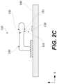
- decontamination system 110 comprises object 140 (e.g., a door) such that UV transparent apparatus 130 (e.g., a door handle) is pivotably attached to object 140 and such that at least one of one or more UV light sources 120 is positioned on object 140.
- object 140 e.g., a door
- UV transparent apparatus 130 e.g., a door handle
- UV light source 120 is positioned on a door.
- one or more UV light sources 120 comprises multiple UV light sources such that a surface area of first transparent surface 131 is greater than a surface area of second transparent surface 132. It should be noted that first transparent surface 131 is a surface with a direct line of sight to one or more UV light sources 120, while second transparent surface 132 does not have a direct line of sights to one or more UV light sources 120. Decontamination of second transparent surface 132 is performed when UV light beams 122 are transmitted through UV transparent apparatus 130.
- UV transparent apparatus 130 comprises non-transparent insert 133.
- non-transparent insert 133 is defined as an object not transparent to wavelengths of between about 200 nanometers and about 240 nanometers (e.g., transparency is less than 10% or even less than 1%).
- one or more UV light sources 120 are positioned such that non-transparent insert 133 does not shadow any surfaces of UV transparent apparatus 130 from UV light beams 122.
- Some examples of non-transparent insert 133 include, but are not limited to, portions of a door used for attaching UV transparent apparatus 130 such as a screw, bolt, or the like, to a UV transparent apparatus such as, for example, a door handle.
- FIG. 5 is a process flowchart corresponding to method 500 for decontaminating aircraft from pathogens using UV light sources 120, in accordance with some examples.
- method 500 comprises illuminating (block 510) one or more UV light sources 120. This illumination operation generates one or more UV light beams 122 with a wavelength of between about 200 nanometers and about 240 nanometers.
- Method 500 proceeds with directing (block 520) one or more UV light beams 122 in a direction of UV transparent apparatus 130.
- UV transparent apparatus 130 comprised first transparent surface 131 and second transparent surface 132.
- First transparent surface 131 is in a direct line of sight of one or more UV light sources 120 such that first transparent surface 131 is directly exposed to one or more UV light beams 122. This direct UV exposure decontaminates first transparent surface 131 from the pathogens.
- second transparent surface 132 is indirectly exposed to one or more UV light beams 122.
- One or more UV light beams 122 pass through UV transparent apparatus 130, between first transparent surface 131 and second transparent surface 132, also through each of first transparent surface 131 and second transparent surface 132. This indirect exposure decontaminates second transparent surface 132 from the pathogens by transmission of one or more UV light beams 122 through UV transparent apparatus 130 between first transparent surface 131 and second transparent surface 132, and
- directing one or more UV light beams 122 onto UV transparent apparatus 130 comprises illuminating at least a portion of object surface 141 of object 140 as, for example, is schematically shown in FIG. 2B .
- UV transparent apparatus 130 is positioned between this portion of object surface 141 and effective "shadowed" from one or more UV light sources 120 by UV transparent apparatus 130.
- this portion of object surface 141 is indirectly exposed by UV light sources 120.
- methods and systems described above are used on aircraft and, more generally, by the aerospace industry. Specifically, these methods and systems can be used during fabrication of aircraft as well as during aircraft service and maintenance.
- method 900 includes specification and design 904 of aircraft 902 and material procurement 906.
- component and subassembly manufacturing 908 and system integration 910 of aircraft 902 takes place.
- aircraft 902 goes through certification and delivery 912 in order to be placed in service 914.
- routine maintenance and service 916 which also includes modification, reconfiguration, refurbishment, and so on.
- each of the processes of method 900 is performed or carried out by a system integrator, a third party, and/or an operator, e.g., a customer.
- a system integrator includes without limitation any number of aircraft manufacturers and major-system subcontractors;
- a third party includes without limitation any number of venders, subcontractors, and suppliers; and
- an operator can be an airline, leasing company, military entity, service organization, and so on.
- aircraft 902 produced by method 900 includes airframe 918 with plurality of systems 920 and interior 922.
- the airframe 918 includes wings of the aircraft 902.
- systems 920 include one or more of propulsion system 924, electrical system 926, hydraulic system 928, and environmental system 930. Any number of other systems can be included.
- Apparatus and methods presented herein can be employed during any one or more of the stages of method 900.
- components or subassemblies corresponding to manufacturing 908 are fabricated or manufactured in a manner similar to components or subassemblies produced while aircraft 902 is in service.
- one or more apparatus examples, method examples, or a combination thereof are utilized during manufacturing 908 and system integration 910, for example, by substantially expediting assembly of or reducing the cost of an aircraft 902.
- one or more of apparatus examples, method examples, or a combination thereof are utilized while aircraft 902 is in service, for example and without limitation, to maintenance and service 916.
Landscapes
- Health & Medical Sciences (AREA)
- Epidemiology (AREA)
- Public Health (AREA)
- Life Sciences & Earth Sciences (AREA)
- Animal Behavior & Ethology (AREA)
- General Health & Medical Sciences (AREA)
- Veterinary Medicine (AREA)
- Engineering & Computer Science (AREA)
- Aviation & Aerospace Engineering (AREA)
- Apparatus For Disinfection Or Sterilisation (AREA)
Abstract
Description
- Commercial aircraft include an interior cabin with various facilities, such as lavatories and galley kitchens. As can be appreciated, during a typical flight, various surfaces in these facilities may become contaminated. For example, passengers and flight attendants contact door handles to access lavatories and may sneeze in proximity to these handles. In short, a door handle and other like components may be covered with various contaminants, such as viruses, bacteria, and other like pathogens or microbial contaminants.
- A conventional approach involves flight attendants periodically cleaning such surfaces. Furthermore, ground-based cleaning personnel conduct comprehensive decontamination between flights. However, there may not be sufficient time to effectively clean each touch surface, e.g., between two consecutive uses. Moreover, individual flight attendants may not thoroughly clean each surface or miss some surfaces. As such, various contaminants may remain on particular surfaces which may pose real and/or perceived health concerns to future passengers.
- Described herein are methods and systems for decontaminating surfaces on aircraft from pathogens using UV lights with wavelengths between about 200 nanometers and about 240 nanometers. These wavelengths are able to effectively decontaminate pathogens while remaining safe to humans. In other words, humans can remain in decontamination zones during operation of these systems. Furthermore, UV transparent apparatuses, such as door, cabinet and other handles, allow decontamination of all surfaces of these apparatuses whether these surfaces are directly or indirectly exposed to the UV light. The indirect exposure is provided by the UV lights passing through the transparent apparatus. Therefore, even surfaces without a line of sight to UV light sources are decontaminated. As such, these methods and systems allow to achieve effective decontamination of an apparatus with a complex surface (e.g., a door, cabinet or otherhandle) without requiring many UV light sources positioned around this apparatus.
-
-
FIG. 1 is a schematic illustration of an aircraft, illustrating decontamination systems positioned in lavatories and galley kitchen of the aircraft, in accordance with some examples. -
FIG. 2A is a schematic side view of a decontamination system, comprising a UV light source and a UV transparent apparatus, such that the UV light source is configured to decontaminate all surfaces of the UV transparent apparatus, in accordance with some examples. -
FIG. 2B is another schematic side view of a decontamination system, comprising a UV light source and a UV transparent apparatus, such that the UV light source is configured to decontaminate all surfaces of the UV transparent apparatus as well as an object surface, shadowed by the UV transparent apparatus, in accordance with some examples. -
FIG. 2C is yet another schematic side view of a decontamination system, comprising a UV light source and a UV transparent apparatus, such that the UV light source is positioned on an object, which supports the UV transparent apparatus, in accordance with some examples. -
FIG. 3A is a plot showing UV transmissivity of one material example for a UV transparent apparatus. -
FIG. 3B is a plot showing lack of UV transmissivity, for wavelengths below 250 nanometers, of conventional borosilicate glass. -
FIG. 4 illustrates absorption plots for DNA and protein as a function of wavelengths in a UV spectrum. -
FIG. 5 is a process flowchart corresponding to method for decontaminating an aircraft from pathogens using a UV light source, in accordance with some examples. -
FIG. 6 is a process flowchart corresponding to a method for manufacturing and servicing the aircraft. -
FIG. 7 illustrates a block diagram of an example aircraft, in accordance with some examples. - In the following description, numerous specific details are set forth in order to provide a thorough understanding of the presented concepts. In some examples, the presented concepts are practiced without some or all of these specific details. In other instances, well known process operations have not been described in detail so as to not unnecessarily obscure the described concepts. While some concepts will be described in conjunction with the specific examples, it will be understood that these examples are not intended to be limiting.
- Decontamination of commercial aircraft can be rather challenging due to various design and operational aspects.
FIG. 1 is a schematic illustration ofaircraft 100, comprisinglavatories 102 andgalley kitchen 104, in accordance with some examples. Each of these facilities is used by multiple different people. For example, each lavatory may be used dozens of time during each flight, especially during long intercontinental flights. Furthermore, each of these facilities comprises multiple surfaces, which may be contaminated via a direct contact (e.g., touch) or an indirect contact (e.g., sneezing, coughing). Some of these surfaces have complex geometries, which makes the decontamination process even more challenging. - While flight attendants may be able to perform some decontamination during the flight, the frequency and thoroughness of this decontamination is limited due to various complexities, described above. Furthermore, while ground-based cleaning personnel conduct comprehensive decontamination between flights, such decontamination is also needed during the flight.
- Methods (described below with reference to
FIG. 5 ) and systems (described below with reference toFIGS. 2A, 2B , and2C ) are configured to decontaminate any complex surfaces on aircraft from pathogens using UV lights with wavelengths between about 200 nanometers and about 240 nanometers, such as about 222 nanometers or about 207 nanometers. As noted above, these wavelengths are able to effectively decontaminate pathogens while remaining safe to humans. In other words, humans can remain in decontamination zones during operation of these systems. - As further described below and without being restricted to any particular theory, this UV subrange is absorbed by the DNA and RNA of microorganisms, which causes changes in the DNA and RNA structure of these microorganisms. These changes render the microorganisms incapable of replicating, which effectively controls the spread. More specifically, these microorganisms are unable to multiply to infectious numbers within a host, such as a human. While conventional approaches focus on a peak of the germicidal effectiveness curve, which corresponds to about 265 nanometer radiation, this wavelength is harmful to humans. As such, these conventional approaches cannot be used while passengers or flight crews are present in areas, requiring decontamination. At the same time, it may not be possible or at least practical to isolate specific areas (e.g., lavatories and galley kitchens) from humans while performing decontamination process. For example, a conventional disinfection cycle lasts about 10-30 minutes, which imposes unreasonable requirements of taking aircraft facilities offline during such a disinfection cycle. Furthermore, conventional approaches are limited to the "line-of-sight" aspect, only irradiating and decontaminating surfaces within a direct line of sight of a UV light source. Surfaces can be blocked from the light if objects are other objects on the way. Furthermore, non-transparent objects have shadow sides, which can still be contaminated and remain contaminated during these conventional decontamination methods.
- Referring again to
FIG. 1 ,aircraft 100 comprisesdecontamination systems 110 positioned in each oflavatories 102 andgalley kitchen 104. Each facility with a risk of pathogen contamination may be designated as a decontamination area anddecontamination system 110 is positioned in this area.Decontamination systems 110 rely on a combination of a specific UV subrange (of between about 200 nanometers and about 240 nanometers) and use of UV transparent apparatuses, such as door handles. The UV transparent apparatuses described herein allow decontamination of all surfaces of these apparatuses whether these surfaces are directly or indirectly exposed to the UV light. The indirect exposure is provided by the UV lights passing through the apparatus. For example, a UV transparent apparatus comprises or is formed entirely from a quartz glass, such as Corning HPFS® Fused Silica 7980. -
FIG. 2A is a schematic side view ofdecontamination system 110 for decontaminating surfaces onaircraft 100 from pathogens, in accordance with some examples.Decontamination system 110 comprises one or more UVlight sources 120 and one of more UVtransparent apparatuses 130. WhileFIG. 2A illustrates oneUV light source 120 and one UVtransparent apparatus 130, one having ordinary skill in the art would understand thatdecontamination system 110 may comprise any number of UVlight sources 120 and UVtransparent apparatuses 130. For example, oneUV light source 120 may be used for decontaminating multiple UVtransparent apparatuses 130, such that all of these UVtransparent apparatuses 130 are within a line of sight of this oneUV light source 120. Alternatively, multipleUV light source 120 may be used for decontaminating one UVtransparent apparatus 130. Finally, multipleUV light source 120 may be used for decontaminating multiple UVtransparent apparatuses 130. - UV
light source 120 is configured to generateUV light beam 122 with a wavelength of between about 200 nanometers and about 240 nanometers, or about 200 to about 222 nm, or from about 207 to about 222 nm. It should be noted that wavelengths of 200-240 nanometers represent a rather small subrange of a shortwave ultraviolet-C, which is conventionally used for ultraviolet germicidal irradiation. The shortwave ultraviolet-C spans 100-280 nanometers. Without being restricted to any particular theory, it is believed that this 200-240 nanometer subrange of is particularly effective with pathogen decontamination while being safe to humans, which will now be described with reference toFIG. 4 . Specifically,FIG. 4 illustrates absorption plots for DNA and protein as a function of wavelengths in a UV spectrum.Line 410 corresponds to the DNA absorption and represents safety of the UV exposure. The lower DNA adsorption is desired from the human safety standpoint.Line 420 corresponds to the protein absorption and decontamination efficiency, with the higher protein absorption corresponding to the higher decontamination efficiency. The UV absorption effectively deactivates pathogen by causing various internal changes. The 200-240 nanometer subrange represents a DNA adsorption "well" with sufficiently high protein absorption. While not shown inFIG. 4 , the decontamination efficiency for wavelengths lower than 200 nanometers. For example, a 172 nanometer wavelength (produced by a xenon-type light source) has about 10 times lower decontamination efficiency for typical pathogens (e.g., fungus) than a 220 nanometer wavelength. - The human safety aspect of the 200-240 nanometer subrange allows operating
UV light source 120 while people are within the line of sight. In other words,decontamination system 110 does not need to monitor presence of the people within the line of sight of UVlight source 120 and selectively turn on and turn offUV light source 120. In some examples,UV light source 120 operates continuously. - In some examples,
UV light source 120 is one of krypton chloride-type light source (producing 222 nanometer wavelengths) or krypton bromide-type light source (producing 207 nanometer wavelengths). Other types of light sources capable of generating wavelengths within the 200-240 nanometer subrange are also within the scope. - Referring to
FIGS. 2A, 2B , and2C , UVtransparent apparatus 130 comprises firsttransparent surface 131 and secondtransparent surface 132, wherein the second surface is shadowed by the first transparent surface. In some embodiments, the second surface is located behind or under the UV transparent apparatus 130 (object 140) and in some examples, the second surface may or may not be transparent. UVtransparent apparatus 130 comprises a material, which is transparent to the wavelength of between about 200 nanometers and about 240 nanometers, such as about 200 nanometers to about 222 nm, or from about 207 nanometers to about 220 nm. This material forms firsttransparent surface 131 and secondtransparent surface 132. This transparency characteristic of UVtransparent apparatus 130 allows UV light beam to pass through UVtransparent apparatus 130 and decontaminate both firsttransparent surface 131 and secondtransparent surface 132. - For example, first
transparent surface 131 is in a direct line of sight of one or more UVlight sources 120 such that firsttransparent surface 131 is directly exposed to one or more UV light beams 122 for decontamination of firsttransparent surface 131 from the pathogens on firsttransparent surface 131. This decontamination occurs by the direct exposure of firsttransparent surface 131. - Second
transparent surface 132 is indirectly exposed to one or more UV light beams 122. Secondtransparent surface 132 is located on the opposite side of the firsttransparent surface 131 and is not in direct line of sight of the UVlight source 120. More specifically, secondtransparent surface 132 is decontaminated from the pathogens by transmission of one or more UV light beams 122 through UVtransparent apparatus 130 between firsttransparent surface 131 and secondtransparent surface 132. More specifically, one or more UV light beams 122 pass through firsttransparent surface 131, through the body of UVtransparent apparatus 130 positioned between firsttransparent surface 131 and secondtransparent surface 132, and finally through secondtransparent surface 132 at which point the pathogens (disposed on second transparent surface 132) are decontaminated. - In some examples, the transmission of one or more UV light beams 122 through UV
transparent apparatus 130 between firsttransparent surface 131 and secondtransparent surface 132 is at least about 80% or, more specifically, from about 80% to about 99% or from about 90% to about 99% and can even reach up to 100%. Such transparency (in the 200-240 nanometer subrange) requires special materials for UVtransparent apparatus 130. For example, UVtransparent apparatus 130 comprises or, more specifically, entire formed from a quartz glass, such as Corning HPFS® Fused Silica 7980 or from a material having UV transmissivity and ability to be sanitized at from about 207 to about 222 nm. In some examples, firsttransparent surface 131 and/or secondtransparent surface 132 is formed from a quartz glass or, more specifically, from a transparent material having UV transmissivity and ability to be sanitized at from about 207 to about 222 nm, or even more specifically, from Corning HPFS® Fused Silica 7980. -
FIG. 3A is a plot showing the UV transmissivity of Corning HPFS® Fused Silica 7980. The transmissivity is at least 99% for the entire 200-240 nanometer subrange. As such, the UV exposure of firsttransparent surface 131 and secondtransparent surface 132 vary minimally UVtransparent apparatus 130 is formed from Corning HPFS® Fused Silica 7980 and when firsttransparent surface 131 is exposed to UVlight sources 120. -
FIG. 3B is a plot showing the UV transmissivity of a conventional borosilicate glass. More specifically, this plot shows the lack of UV transmissivity, for wavelengths below 250 nanometers, of conventional borosilicate glass. - Referring to
FIGS. 2A, 2B , and2C , in some examples, UVtransparent apparatus 130 is a handle or, more specifically, is a door handle. In generally, UVtransparent apparatus 130 may be any object with a surface subjected to contamination (e.g., via touching or other means). In a specific example, UVtransparent apparatus 130 is a door handle ofairplane lavatory 102. - Referring to
FIGS. 2A and 2B , in some examples,decontamination system 110 further comprisesobject 140, comprisingobject surface 141. For example, object 140 may be a door, while UVtransparent apparatus 130 is a door handle, pivotably attached to the door. At least a portion ofobject surface 141 is within a direct light of sight of one or more UVlight sources 120. More specifically, UVtransparent apparatus 130 is positioned between one or more UVlight sources 120 and this portion ofobject surface 141 and effectively "shadows" the portion ofobject surface 141. However, due to the transparency of UVtransparent apparatus 130 to UV light beams 122, this portion ofobject surface 141 is indirectly exposed to one or more UV light beams 122. This UV exposure of the portion ofobject surface 141 provides the decontamination of the portion ofobject surface 141 from the pathogens. More specifically, one or more UV light beams 122 are transmitted through UVtransparent apparatus 130 between firsttransparent surface 131 and secondtransparent surface 132 and through a space between secondtransparent surface 132 and the portion ofobject surface 141 and deactivate the pathogens on the portion ofobject surface 141. - Referring to
FIG. 2C , in some examples,decontamination system 110 comprises object 140 (e.g., a door) such that UV transparent apparatus 130 (e.g., a door handle) is pivotably attached to object 140 and such that at least one of one or more UVlight sources 120 is positioned onobject 140. For example,UV light source 120 is positioned on a door. - In some examples, one or more UV
light sources 120 comprises multiple UV light sources such that a surface area of firsttransparent surface 131 is greater than a surface area of secondtransparent surface 132. It should be noted that firsttransparent surface 131 is a surface with a direct line of sight to one or more UVlight sources 120, while secondtransparent surface 132 does not have a direct line of sights to one or more UVlight sources 120. Decontamination of secondtransparent surface 132 is performed when UV light beams 122 are transmitted through UVtransparent apparatus 130. - Referring to
FIG. 2B , in some examples, UVtransparent apparatus 130 comprisesnon-transparent insert 133. For purposed of this disclosure,non-transparent insert 133 is defined as an object not transparent to wavelengths of between about 200 nanometers and about 240 nanometers (e.g., transparency is less than 10% or even less than 1%). In this example, one or more UVlight sources 120 are positioned such thatnon-transparent insert 133 does not shadow any surfaces of UVtransparent apparatus 130 from UV light beams 122. Some examples ofnon-transparent insert 133 include, but are not limited to, portions of a door used for attaching UVtransparent apparatus 130 such as a screw, bolt, or the like, to a UV transparent apparatus such as, for example, a door handle. -
FIG. 5 is a process flowchart corresponding tomethod 500 for decontaminating aircraft from pathogens usingUV light sources 120, in accordance with some examples. - In some examples,
method 500 comprises illuminating (block 510) one or more UVlight sources 120. This illumination operation generates one or more UV light beams 122 with a wavelength of between about 200 nanometers and about 240 nanometers. -
Method 500 proceeds with directing (block 520) one or more UV light beams 122 in a direction of UVtransparent apparatus 130. Various examples of UVtransparent apparatus 130 are described above with reference toFIGS. 2A, 2B , and2C . In some examples, UVtransparent apparatus 130 comprised firsttransparent surface 131 and secondtransparent surface 132. Firsttransparent surface 131 is in a direct line of sight of one or more UVlight sources 120 such that firsttransparent surface 131 is directly exposed to one or more UV light beams 122. This direct UV exposure decontaminates firsttransparent surface 131 from the pathogens. Furthermore, secondtransparent surface 132 is indirectly exposed to one or more UV light beams 122. One or more UV light beams 122 pass through UVtransparent apparatus 130, between firsttransparent surface 131 and secondtransparent surface 132, also through each of firsttransparent surface 131 and secondtransparent surface 132. This indirect exposure decontaminates secondtransparent surface 132 from the pathogens by transmission of one or more UV light beams 122 through UVtransparent apparatus 130 between firsttransparent surface 131 and secondtransparent surface 132, and - In some examples, directing one or more UV light beams 122 onto UV
transparent apparatus 130 comprises illuminating at least a portion ofobject surface 141 ofobject 140 as, for example, is schematically shown inFIG. 2B . UVtransparent apparatus 130 is positioned between this portion ofobject surface 141 and effective "shadowed" from one or more UVlight sources 120 by UVtransparent apparatus 130. However, due to the transparency of UVtransparent apparatus 130 to wavelengths between about 200 nanometers and about 240 nanometers, this portion ofobject surface 141 is indirectly exposed by UVlight sources 120. - In some examples, methods and systems described above are used on aircraft and, more generally, by the aerospace industry. Specifically, these methods and systems can be used during fabrication of aircraft as well as during aircraft service and maintenance.
- Accordingly, the apparatus and methods described above are applicable for aircraft manufacturing and
service method 900 as shown inFIG. 6 and foraircraft 902 as shown inFIG. 7 . During pre-production,method 900 includes specification anddesign 904 ofaircraft 902 andmaterial procurement 906. During production, component andsubassembly manufacturing 908 andsystem integration 910 ofaircraft 902 takes place. Thereafter,aircraft 902 goes through certification anddelivery 912 in order to be placed inservice 914. While in service by a customer,aircraft 902 is scheduled for routine maintenance andservice 916, which also includes modification, reconfiguration, refurbishment, and so on. - In some examples, each of the processes of
method 900 is performed or carried out by a system integrator, a third party, and/or an operator, e.g., a customer. For the purposes of this description, a system integrator includes without limitation any number of aircraft manufacturers and major-system subcontractors; a third party includes without limitation any number of venders, subcontractors, and suppliers; and an operator can be an airline, leasing company, military entity, service organization, and so on. - As shown in
FIG. 7 ,aircraft 902 produced bymethod 900 includesairframe 918 with plurality ofsystems 920 and interior 922. Theairframe 918 includes wings of theaircraft 902. Examples ofsystems 920 include one or more ofpropulsion system 924,electrical system 926,hydraulic system 928, andenvironmental system 930. Any number of other systems can be included. - Apparatus and methods presented herein can be employed during any one or more of the stages of
method 900. For example, components or subassemblies corresponding to manufacturing 908 are fabricated or manufactured in a manner similar to components or subassemblies produced whileaircraft 902 is in service. Also, one or more apparatus examples, method examples, or a combination thereof are utilized duringmanufacturing 908 andsystem integration 910, for example, by substantially expediting assembly of or reducing the cost of anaircraft 902. Similarly, one or more of apparatus examples, method examples, or a combination thereof are utilized whileaircraft 902 is in service, for example and without limitation, to maintenance andservice 916. - Further, the disclosure comprises embodiments according to the following Clauses:
- 1. A decontamination system (110) for decontaminating surfaces on an aircraft (100) from pathogens, the decontamination system (110) comprising:
- one or more UV light sources (120), configured to generate one or more UV light beams (122) with a wavelength of between about 200 nanometers and about 240 nanometers; and
- a UV transparent apparatus (130), comprising a first transparent surface (131) and a second transparent surface (132),
- wherein the UV transparent apparatus (130) comprising a material, transparent to the wavelength of between about 200 nanometers and about 240 nanometers, the material forming the first transparent surface (131) and the second transparent surface (132),
- wherein the first transparent surface (131) is in a direct line of sight of the one or more UV light sources (120) such that the first transparent surface (131) is directly exposed to the one or more UV light beams (122) for decontamination of the first transparent surface (131) from the pathogens,
- wherein the second transparent surface (132) is indirectly exposed to the one or more UV light beams (122) and wherein the second transparent surface (132) is decontaminated from the pathogens by transmission of the one or more UV light beams (122) through the UV transparent apparatus (130) between the first transparent surface (131) and the second transparent surface (132), and
- wherein the transmission of the one or more UV light beams (122) through the UV transparent apparatus (130) between the first transparent surface (131) and the second transparent surface (132) is at least about 80%.
- 2. The decontamination system (110) of Clause 1, wherein the transmission of the one or more UV light beams (122) through the UV transparent apparatus (130) between the first transparent surface (131) and the second transparent surface (132) is at least about 90%.
- 3. The decontamination system (110) of
Clauses 1 or 2, wherein the first transparent surface (131) is formed from a quartz glass. - 4. The decontamination system (110) of any of Clauses 1 to 3, wherein the first transparent surface (131) is formed from Corning HPFS® Fused Silica 7980.
- 5. The decontamination system (110) of any of Clauses 1 to 4, wherein the UV transparent apparatus (130) is a door handle.
- 6. The decontamination system (110) of any of Clauses 1 to 5, wherein the UV transparent apparatus (130) is a door handle of an airplane lavatory (102).
- 7. The decontamination system (110) of any of Clauses 1 to 6, further comprising an object (140), comprising an object surface (141), wherein at least a portion of the object surface (141) is not within the direct line of sight of the one or more UV light sources (120) such that at least the portion of the object surface (141) is indirectly exposed to the one or more UV light beams (122), for decontaminating at least the portion of the object surface (141) from the pathogens, by transmission of the one or more UV light beams (122) through the UV transparent apparatus (130) between the first transparent surface (131) and the second transparent surface (132) and through a space between the second transparent surface (132) and at least the portion of the object surface (141).
- 8. The decontamination system (110) of any of Clauses 1 to 7, wherein the UV transparent apparatus (130) is pivotably attached to the object (140).
- 9. The decontamination system (110) of any of Clauses 1 to 8, further comprising an object (140), wherein:
- the UV transparent apparatus (130) is pivotably attached to the object (140), and
- at least one of the one or more UV light sources (120) is positioned on the object (140).
- 10. The decontamination system (110) of any of Clauses 1 to 9, wherein the one or more UV light sources (120) comprises multiple UV light sources such that a surface area of the first transparent surface (131) is greater than a surface area of the second transparent surface (132).
- 11. A UV transparent apparatus (130) for use on an aircraft (100), comprising one or more UV light sources (120), configured to generate one or more UV light beams (122) with a wavelength of between 200 nanometers and 240 nanometers for decontaminating the aircraft (100) from pathogens, the UV transparent apparatus (130) comprising:
- a first transparent surface (131), positioned in a direct line of sight of the one or more UV light sources (120) such that the first transparent surface (131) is directly exposed to the one or more UV light beams (122) for decontamination of the first transparent surface (131) from the pathogens; and
- a second transparent surface (132), indirectly exposed to the one or more UV light beams (122) and wherein the second transparent surface (132) is decontaminated from the pathogens by transmission of the one or more UV light beams (122) through the UV transparent apparatus (130) between the first transparent surface (131) and the second transparent surface (132),
- wherein the transmission of the one or more UV light beams (122) through the UV transparent apparatus (130) between the first transparent surface (131) and the second transparent surface (132) is at least 80%.
- 12. The UV transparent apparatus (130) of Clause 11, wherein the transmission of the one or more UV light beams (122) through the UV transparent apparatus (130) between the first transparent surface (131) and the second transparent surface (132) is at least 90%.
- 13. The UV transparent apparatus (130) of Clauses 11 or 12, wherein the first transparent surface (131) comprises a material having ability to be transparent and sanitized at a UV wavelength of about 222 nm.
- 14. The UV transparent apparatus (130) of any of Clauses 11 - 13, wherein the first transparent surface (131) is formed from Corning HPFS® Fused Silica 7980.
- 15. The UV transparent apparatus (130) of any of Clauses 11 to 14, wherein the UV transparent apparatus (130) is a door handle of a lavatory (102).
- 16. A method (500) for decontaminating surfaces on an aircraft (100) from pathogens, the method (500) comprising:
- illuminating (510) one or more UV light sources (120), thereby generating one or more UV light beams (122) with a wavelength of between about 200 nanometers and about 240 nanometers; and
- directing (520) the one or more UV light beams (122) in a direction of a UV transparent apparatus (130), comprising a first transparent surface (131) and a second transparent surface (132), wherein:
- the first transparent surface (131) is in a direct line of sight of the one or more UV light sources (120) such that the first transparent surface (131) is directly exposed to the one or more UV light beams (122) for decontamination of the first transparent surface (131) from the pathogens,
- the second transparent surface (132) is indirectly exposed to the one or more UV light beams (122) and wherein the second transparent surface (132) is decontaminated from the pathogens by transmission of the one or more UV light beams (122) through the UV transparent apparatus (130) between the first transparent surface (131) and the second transparent surface (132), and
- the transmission of the one or more UV light beams (122) through the UV transparent apparatus (130) between the first transparent surface (131) and the second transparent surface (132) is at least 80%.
- 17. The method (500) of Clause 16, wherein the first transparent surface (131) is formed by a material having ability to be transparent and sanitized at the wavelength of between about 200 nanometers and about 240 nanometers.
- 18. The method (500) of Clauses 16 and 17, wherein directing the one or more UV light beams (122) onto the UV transparent apparatus (130) comprises illuminating at least a portion of an object surface (141) of an object (140) shadowed from the one or more UV light sources (120) by the UV transparent apparatus (130).
- 19. The method (500) of any of Clauses 16 to 18, wherein the object (140) is a door of a lavatory (102) on the aircraft (100), and wherein the UV transparent apparatus (130) is pivotably coupled to the object (140).
- 20. The method (500) of any of Clauses 16 to 19, wherein the UV transparent apparatus (130) is formed from Corning HPFS® Fused Silica 7980.
- Although the foregoing concepts have been described in some detail for purposes of clarity of understanding, it will be apparent that certain changes and modifications may be practiced within the scope of the appended claims. It should be noted that there are many alternative ways of implementing the processes, systems, and apparatus. Accordingly, the present examples are to be considered as illustrative and not restrictive.
Claims (15)
- A decontamination system (110) for decontaminating surfaces on an aircraft (100) from pathogens, the decontamination system (110) comprising:one or more UV light sources (120), configured to generate one or more UV light beams (122) with a wavelength of between about 200 nanometers and about 240 nanometers; anda UV transparent apparatus (130), comprising a first transparent surface (131) and a second transparent surface (132),wherein the UV transparent apparatus (130) comprising a material, transparent to the wavelength of between about 200 nanometers and about 240 nanometers, the material forming the first transparent surface (131) and the second transparent surface (132),wherein the first transparent surface (131) is in a direct line of sight of the one or more UV light sources (120) such that the first transparent surface (131) is directly exposed to the one or more UV light beams (122) for decontamination of the first transparent surface (131) from the pathogens,wherein the second transparent surface (132) is indirectly exposed to the one or more UV light beams (122) and wherein the second transparent surface (132) is decontaminated from the pathogens by transmission of the one or more UV light beams (122) through the UV transparent apparatus (130) between the first transparent surface (131) and the second transparent surface (132), andwherein the transmission of the one or more UV light beams (122) through the UV transparent apparatus (130) between the first transparent surface (131) and the second transparent surface (132) is at least about 80%.
- The decontamination system (110) of claim 1, wherein the transmission of the one or more UV light beams (122) through the UV transparent apparatus (130) between the first transparent surface (131) and the second transparent surface (132) is at least about 90%.
- The decontamination system (110) of claims 1 or 2, wherein the first transparent surface (131) is formed from a quartz glass.
- The decontamination system (110) of any of claims 1 to 3, wherein the first transparent surface (131) is formed from Corning HPFS® Fused Silica 7980.
- The decontamination system (110) of any of claims 1 to 4, wherein the UV transparent apparatus (130) is a door handle.
- The decontamination system (110) of any of claims 1 to 5, further comprising an object (140), comprising an object surface (141), wherein at least a portion of the object surface (141) is not within the direct line of sight of the one or more UV light sources (120) such that at least the portion of the object surface (141) is indirectly exposed to the one or more UV light beams (122), for decontaminating at least the portion of the object surface (141) from the pathogens, by transmission of the one or more UV light beams (122) through the UV transparent apparatus (130) between the first transparent surface (131) and the second transparent surface (132) and through a space between the second transparent surface (132) and at least the portion of the object surface (141).
- The decontamination system (110) of claim 6, wherein the UV transparent apparatus (130) is pivotably attached to the object (140).
- A UV transparent apparatus (130) for use on an aircraft (100), comprising one or more UV light sources (120), configured to generate one or more UV light beams (122) with a wavelength of between 200 nanometers and 240 nanometers for decontaminating the aircraft (100) from pathogens, the UV transparent apparatus (130) comprising:a first transparent surface (131), positioned in a direct line of sight of the one or more UV light sources (120) such that the first transparent surface (131) is directly exposed to the one or more UV light beams (122) for decontamination of the first transparent surface (131) from the pathogens; anda second transparent surface (132), indirectly exposed to the one or more UV light beams (122) and wherein the second transparent surface (132) is decontaminated from the pathogens by transmission of the one or more UV light beams (122) through the UV transparent apparatus (130) between the first transparent surface (131) and the second transparent surface (132),wherein the transmission of the one or more UV light beams (122) through the UV transparent apparatus (130) between the first transparent surface (131) and the second transparent surface (132) is at least 80%.
- The UV transparent apparatus (130) of claim 8, wherein the transmission of the one or more UV light beams (122) through the UV transparent apparatus (130) between the first transparent surface (131) and the second transparent surface (132) is at least 90%.
- The UV transparent apparatus (130) of claims 8 or 9, wherein the first transparent surface (131) comprises a material having ability to be transparent and sanitized at a UV wavelength of between about 200 nanometers and about 240 nanometers .
- The UV transparent apparatus (130) of any of claims 8 to 10, wherein the first transparent surface (131) is formed from Corning HPFS® Fused Silica 7980.
- The UV transparent apparatus (130) of any of claims 9 to 11, wherein the UV transparent apparatus (130) is a door handle of a lavatory (102).
- A method (500) for decontaminating surfaces on an aircraft (100) from pathogens, the method (500) comprising:illuminating (510) one or more UV light sources (120), thereby generating one or more UV light beams (122) with a wavelength of between about 200 nanometers and about 240 nanometers; anddirecting (520) the one or more UV light beams (122) in a direction of a UV transparent apparatus (130), comprising a first transparent surface (131) and a second transparent surface (132), wherein:the first transparent surface (131) is in a direct line of sight of the one or more UV light sources (120) such that the first transparent surface (131) is directly exposed to the one or more UV light beams (122) for decontamination of the first transparent surface (131) from the pathogens,the second transparent surface (132) is indirectly exposed to the one or more UV light beams (122) and wherein the second transparent surface (132) is decontaminated from the pathogens by transmission of the one or more UV light beams (122) through the UV transparent apparatus (130) between the first transparent surface (131) and the second transparent surface (132), andthe transmission of the one or more UV light beams (122) through the UV transparent apparatus (130) between the first transparent surface (131) and the second transparent surface (132) is at least 80%.
- The method (500) of claim 13, wherein directing the one or more UV light beams (122) onto the UV transparent apparatus (130) comprises illuminating at least a portion of an object surface (141) of an object (140) shadowed from the one or more UV light sources (120) by the UV transparent apparatus (130).
- The method (500) of claims 13 or 14, wherein the object (140) is a door of a lavatory (102) on the aircraft (100), and wherein the UV transparent apparatus (130) is pivotably coupled to the object (140, and wherein the UV transparent apparatus (130) is formed from Corning HPFS® Fused Silica 7980.
Applications Claiming Priority (2)
| Application Number | Priority Date | Filing Date | Title |
|---|---|---|---|
| US202063044624P | 2020-06-26 | 2020-06-26 | |
| US17/343,425 US12318494B2 (en) | 2020-06-26 | 2021-06-09 | Methods and systems for UV-based aircraft decontamination |
Publications (2)
| Publication Number | Publication Date |
|---|---|
| EP3964240A1 true EP3964240A1 (en) | 2022-03-09 |
| EP3964240B1 EP3964240B1 (en) | 2023-11-01 |
Family
ID=76623919
Family Applications (1)
| Application Number | Title | Priority Date | Filing Date |
|---|---|---|---|
| EP21181687.1A Active EP3964240B1 (en) | 2020-06-26 | 2021-06-25 | Methods and systems for uv-based aircraft decontamination |
Country Status (4)
| Country | Link |
|---|---|
| US (1) | US12318494B2 (en) |
| EP (1) | EP3964240B1 (en) |
| JP (2) | JP2022008267A (en) |
| CN (1) | CN113842477A (en) |
Citations (4)
| Publication number | Priority date | Publication date | Assignee | Title |
|---|---|---|---|---|
| US20170081874A1 (en) * | 2015-09-23 | 2017-03-23 | Christopher C. Daniels | Self-sterilizing door handle |
| US20170333580A1 (en) * | 2016-05-18 | 2017-11-23 | International Business Machines Corporation | Automatic Eradication of Bio-Related Contaminants from Handles |
| CN108915361A (en) * | 2018-07-30 | 2018-11-30 | 苏州汇影光学技术有限公司 | A kind of disinfection door |
| EP3913169A1 (en) * | 2020-05-22 | 2021-11-24 | Simmonds Precision Products, Inc. | Germicidal handles |
Family Cites Families (2)
| Publication number | Priority date | Publication date | Assignee | Title |
|---|---|---|---|---|
| US20110291995A1 (en) | 2010-05-25 | 2011-12-01 | Industrial Technology Research Institute | Sterilizing device and manufacturing method for sterilizing device |
| BR112020023865A2 (en) | 2018-06-08 | 2021-04-13 | Stephen R. Wood | DEVICE WITH A SELF-DISINFECTING SURFACE |
-
2021
- 2021-06-09 US US17/343,425 patent/US12318494B2/en active Active
- 2021-06-25 EP EP21181687.1A patent/EP3964240B1/en active Active
- 2021-06-28 CN CN202110717957.8A patent/CN113842477A/en active Pending
- 2021-06-28 JP JP2021106399A patent/JP2022008267A/en active Pending
-
2025
- 2025-11-10 JP JP2025188969A patent/JP2026041742A/en active Pending
Patent Citations (4)
| Publication number | Priority date | Publication date | Assignee | Title |
|---|---|---|---|---|
| US20170081874A1 (en) * | 2015-09-23 | 2017-03-23 | Christopher C. Daniels | Self-sterilizing door handle |
| US20170333580A1 (en) * | 2016-05-18 | 2017-11-23 | International Business Machines Corporation | Automatic Eradication of Bio-Related Contaminants from Handles |
| CN108915361A (en) * | 2018-07-30 | 2018-11-30 | 苏州汇影光学技术有限公司 | A kind of disinfection door |
| EP3913169A1 (en) * | 2020-05-22 | 2021-11-24 | Simmonds Precision Products, Inc. | Germicidal handles |
Also Published As
| Publication number | Publication date |
|---|---|
| CN113842477A (en) | 2021-12-28 |
| EP3964240B1 (en) | 2023-11-01 |
| JP2026041742A (en) | 2026-03-10 |
| JP2022008267A (en) | 2022-01-13 |
| US20210402023A1 (en) | 2021-12-30 |
| US12318494B2 (en) | 2025-06-03 |
Similar Documents
| Publication | Publication Date | Title |
|---|---|---|
| EP3287146B1 (en) | Multi-wavelength ultraviolet light sanitizing systems and methods | |
| CA3009704C (en) | Cleanliness indication systems and methods | |
| EP2049227B1 (en) | Filter unit | |
| CN101238363A (en) | Method and apparatus for sterilizing and disinfecting air and surfaces and protecting an area from contamination by external microorganisms | |
| EP3943116A1 (en) | Ultraviolet wand | |
| US12318494B2 (en) | Methods and systems for UV-based aircraft decontamination | |
| EP4072823B1 (en) | Method and installation for manufacturing and treating sterile plastic containers | |
| CN112955290B (en) | Self-sterilizing robot and method for sterilizing a robot | |
| US11046153B1 (en) | Three stage air purification for rail vehicles | |
| DE202020001894U1 (en) | Arrangement for disinfecting touchscreens using UV LED rays | |
| EP4115912B1 (en) | Sanitization systems and methods | |
| Imbriaco et al. | The organization of ambulance decontamination during the COVID-19 pandemic: a process analysis based on the Lean Thinking philosophy. | |
| DE102019211247A1 (en) | COLD AIR THERAPY UNIT, METHOD OF APPLYING A COOLED AIR FLOW AND USING AN AIR PURIFICATION DEVICE | |
| Smith | Ultraviolet-C radiation: A supplemental tool for disinfection | |
| WO2021211751A1 (en) | Laser systems, methods and devices of processing and sanitizing air flow and surfaces | |
| CN216940666U (en) | Robot device for aircraft cabin disinfection | |
| Ulinici et al. | On the design of an isolated booth for tuberculosis sample collection | |
| DE202020001190U1 (en) | Disinfection device for the disinfection of objects and transparent liquids | |
| DE102024130764A1 (en) | System for the particulate and microbiological removal and inactivation of goods | |
| US12496368B2 (en) | Light conversion systems, methods, and devices | |
| US12201737B2 (en) | Sanitization systems and methods with UVC lighting | |
| DE102024130769A1 (en) | System for the particulate and microbiological removal and inactivation of goods using a conveyor system | |
| DE102020118636A1 (en) | Conveyor belt with photocatalytic effect | |
| DE102024119333A1 (en) | Method and apparatus for sterilizing container transport equipment | |
| Razuri-Madrid¹ et al. | Design and Development of a UVC Ray Disinfection System for Personal Protective Equipment in High-Demand |
Legal Events
| Date | Code | Title | Description |
|---|---|---|---|
| PUAI | Public reference made under article 153(3) epc to a published international application that has entered the european phase |
Free format text: ORIGINAL CODE: 0009012 |
|
| STAA | Information on the status of an ep patent application or granted ep patent |
Free format text: STATUS: THE APPLICATION HAS BEEN PUBLISHED |
|
| AK | Designated contracting states |
Kind code of ref document: A1 Designated state(s): AL AT BE BG CH CY CZ DE DK EE ES FI FR GB GR HR HU IE IS IT LI LT LU LV MC MK MT NL NO PL PT RO RS SE SI SK SM TR |
|
| STAA | Information on the status of an ep patent application or granted ep patent |
Free format text: STATUS: REQUEST FOR EXAMINATION WAS MADE |
|
| 17P | Request for examination filed |
Effective date: 20220701 |
|
| RBV | Designated contracting states (corrected) |
Designated state(s): AL AT BE BG CH CY CZ DE DK EE ES FI FR GB GR HR HU IE IS IT LI LT LU LV MC MK MT NL NO PL PT RO RS SE SI SK SM TR |
|
| STAA | Information on the status of an ep patent application or granted ep patent |
Free format text: STATUS: EXAMINATION IS IN PROGRESS |
|
| RAP3 | Party data changed (applicant data changed or rights of an application transferred) |
Owner name: THE BOEING COMPANY |
|
| 17Q | First examination report despatched |
Effective date: 20230222 |
|
| GRAP | Despatch of communication of intention to grant a patent |
Free format text: ORIGINAL CODE: EPIDOSNIGR1 |
|
| STAA | Information on the status of an ep patent application or granted ep patent |
Free format text: STATUS: GRANT OF PATENT IS INTENDED |
|
| INTG | Intention to grant announced |
Effective date: 20230822 |
|
| GRAS | Grant fee paid |
Free format text: ORIGINAL CODE: EPIDOSNIGR3 |
|
| GRAA | (expected) grant |
Free format text: ORIGINAL CODE: 0009210 |
|
| STAA | Information on the status of an ep patent application or granted ep patent |
Free format text: STATUS: THE PATENT HAS BEEN GRANTED |
|
| P01 | Opt-out of the competence of the unified patent court (upc) registered |
Effective date: 20230824 |
|
| AK | Designated contracting states |
Kind code of ref document: B1 Designated state(s): AL AT BE BG CH CY CZ DE DK EE ES FI FR GB GR HR HU IE IS IT LI LT LU LV MC MK MT NL NO PL PT RO RS SE SI SK SM TR |
|
| REG | Reference to a national code |
Ref country code: GB Ref legal event code: FG4D |
|
| REG | Reference to a national code |
Ref country code: CH Ref legal event code: EP |
|
| REG | Reference to a national code |
Ref country code: DE Ref legal event code: R096 Ref document number: 602021006351 Country of ref document: DE |
|
| REG | Reference to a national code |
Ref country code: IE Ref legal event code: FG4D |
|
| REG | Reference to a national code |
Ref country code: LT Ref legal event code: MG9D |
|
| REG | Reference to a national code |
Ref country code: NL Ref legal event code: MP Effective date: 20231101 |
|
| PG25 | Lapsed in a contracting state [announced via postgrant information from national office to epo] |
Ref country code: GR Free format text: LAPSE BECAUSE OF FAILURE TO SUBMIT A TRANSLATION OF THE DESCRIPTION OR TO PAY THE FEE WITHIN THE PRESCRIBED TIME-LIMIT Effective date: 20240202 |
|
| PG25 | Lapsed in a contracting state [announced via postgrant information from national office to epo] |
Ref country code: IS Free format text: LAPSE BECAUSE OF FAILURE TO SUBMIT A TRANSLATION OF THE DESCRIPTION OR TO PAY THE FEE WITHIN THE PRESCRIBED TIME-LIMIT Effective date: 20240301 |
|
| PG25 | Lapsed in a contracting state [announced via postgrant information from national office to epo] |
Ref country code: LT Free format text: LAPSE BECAUSE OF FAILURE TO SUBMIT A TRANSLATION OF THE DESCRIPTION OR TO PAY THE FEE WITHIN THE PRESCRIBED TIME-LIMIT Effective date: 20231101 |
|
| REG | Reference to a national code |
Ref country code: AT Ref legal event code: MK05 Ref document number: 1626479 Country of ref document: AT Kind code of ref document: T Effective date: 20231101 |
|
| PG25 | Lapsed in a contracting state [announced via postgrant information from national office to epo] |
Ref country code: NL Free format text: LAPSE BECAUSE OF FAILURE TO SUBMIT A TRANSLATION OF THE DESCRIPTION OR TO PAY THE FEE WITHIN THE PRESCRIBED TIME-LIMIT Effective date: 20231101 |
|
| PG25 | Lapsed in a contracting state [announced via postgrant information from national office to epo] |
Ref country code: AT Free format text: LAPSE BECAUSE OF FAILURE TO SUBMIT A TRANSLATION OF THE DESCRIPTION OR TO PAY THE FEE WITHIN THE PRESCRIBED TIME-LIMIT Effective date: 20231101 |
|
| PG25 | Lapsed in a contracting state [announced via postgrant information from national office to epo] |
Ref country code: ES Free format text: LAPSE BECAUSE OF FAILURE TO SUBMIT A TRANSLATION OF THE DESCRIPTION OR TO PAY THE FEE WITHIN THE PRESCRIBED TIME-LIMIT Effective date: 20231101 |
|
| PG25 | Lapsed in a contracting state [announced via postgrant information from national office to epo] |
Ref country code: NL Free format text: LAPSE BECAUSE OF FAILURE TO SUBMIT A TRANSLATION OF THE DESCRIPTION OR TO PAY THE FEE WITHIN THE PRESCRIBED TIME-LIMIT Effective date: 20231101 Ref country code: LT Free format text: LAPSE BECAUSE OF FAILURE TO SUBMIT A TRANSLATION OF THE DESCRIPTION OR TO PAY THE FEE WITHIN THE PRESCRIBED TIME-LIMIT Effective date: 20231101 Ref country code: IS Free format text: LAPSE BECAUSE OF FAILURE TO SUBMIT A TRANSLATION OF THE DESCRIPTION OR TO PAY THE FEE WITHIN THE PRESCRIBED TIME-LIMIT Effective date: 20240301 Ref country code: GR Free format text: LAPSE BECAUSE OF FAILURE TO SUBMIT A TRANSLATION OF THE DESCRIPTION OR TO PAY THE FEE WITHIN THE PRESCRIBED TIME-LIMIT Effective date: 20240202 Ref country code: ES Free format text: LAPSE BECAUSE OF FAILURE TO SUBMIT A TRANSLATION OF THE DESCRIPTION OR TO PAY THE FEE WITHIN THE PRESCRIBED TIME-LIMIT Effective date: 20231101 Ref country code: BG Free format text: LAPSE BECAUSE OF FAILURE TO SUBMIT A TRANSLATION OF THE DESCRIPTION OR TO PAY THE FEE WITHIN THE PRESCRIBED TIME-LIMIT Effective date: 20240201 Ref country code: AT Free format text: LAPSE BECAUSE OF FAILURE TO SUBMIT A TRANSLATION OF THE DESCRIPTION OR TO PAY THE FEE WITHIN THE PRESCRIBED TIME-LIMIT Effective date: 20231101 Ref country code: PT Free format text: LAPSE BECAUSE OF FAILURE TO SUBMIT A TRANSLATION OF THE DESCRIPTION OR TO PAY THE FEE WITHIN THE PRESCRIBED TIME-LIMIT Effective date: 20240301 |
|
| PG25 | Lapsed in a contracting state [announced via postgrant information from national office to epo] |
Ref country code: SE Free format text: LAPSE BECAUSE OF FAILURE TO SUBMIT A TRANSLATION OF THE DESCRIPTION OR TO PAY THE FEE WITHIN THE PRESCRIBED TIME-LIMIT Effective date: 20231101 Ref country code: RS Free format text: LAPSE BECAUSE OF FAILURE TO SUBMIT A TRANSLATION OF THE DESCRIPTION OR TO PAY THE FEE WITHIN THE PRESCRIBED TIME-LIMIT Effective date: 20231101 Ref country code: PL Free format text: LAPSE BECAUSE OF FAILURE TO SUBMIT A TRANSLATION OF THE DESCRIPTION OR TO PAY THE FEE WITHIN THE PRESCRIBED TIME-LIMIT Effective date: 20231101 Ref country code: NO Free format text: LAPSE BECAUSE OF FAILURE TO SUBMIT A TRANSLATION OF THE DESCRIPTION OR TO PAY THE FEE WITHIN THE PRESCRIBED TIME-LIMIT Effective date: 20240201 Ref country code: LV Free format text: LAPSE BECAUSE OF FAILURE TO SUBMIT A TRANSLATION OF THE DESCRIPTION OR TO PAY THE FEE WITHIN THE PRESCRIBED TIME-LIMIT Effective date: 20231101 Ref country code: HR Free format text: LAPSE BECAUSE OF FAILURE TO SUBMIT A TRANSLATION OF THE DESCRIPTION OR TO PAY THE FEE WITHIN THE PRESCRIBED TIME-LIMIT Effective date: 20231101 |
|
| PG25 | Lapsed in a contracting state [announced via postgrant information from national office to epo] |
Ref country code: DK Free format text: LAPSE BECAUSE OF FAILURE TO SUBMIT A TRANSLATION OF THE DESCRIPTION OR TO PAY THE FEE WITHIN THE PRESCRIBED TIME-LIMIT Effective date: 20231101 |
|
| PG25 | Lapsed in a contracting state [announced via postgrant information from national office to epo] |
Ref country code: CZ Free format text: LAPSE BECAUSE OF FAILURE TO SUBMIT A TRANSLATION OF THE DESCRIPTION OR TO PAY THE FEE WITHIN THE PRESCRIBED TIME-LIMIT Effective date: 20231101 |
|
| PG25 | Lapsed in a contracting state [announced via postgrant information from national office to epo] |
Ref country code: SK Free format text: LAPSE BECAUSE OF FAILURE TO SUBMIT A TRANSLATION OF THE DESCRIPTION OR TO PAY THE FEE WITHIN THE PRESCRIBED TIME-LIMIT Effective date: 20231101 |
|
| PG25 | Lapsed in a contracting state [announced via postgrant information from national office to epo] |
Ref country code: SM Free format text: LAPSE BECAUSE OF FAILURE TO SUBMIT A TRANSLATION OF THE DESCRIPTION OR TO PAY THE FEE WITHIN THE PRESCRIBED TIME-LIMIT Effective date: 20231101 Ref country code: SK Free format text: LAPSE BECAUSE OF FAILURE TO SUBMIT A TRANSLATION OF THE DESCRIPTION OR TO PAY THE FEE WITHIN THE PRESCRIBED TIME-LIMIT Effective date: 20231101 Ref country code: IT Free format text: LAPSE BECAUSE OF FAILURE TO SUBMIT A TRANSLATION OF THE DESCRIPTION OR TO PAY THE FEE WITHIN THE PRESCRIBED TIME-LIMIT Effective date: 20231101 Ref country code: EE Free format text: LAPSE BECAUSE OF FAILURE TO SUBMIT A TRANSLATION OF THE DESCRIPTION OR TO PAY THE FEE WITHIN THE PRESCRIBED TIME-LIMIT Effective date: 20231101 Ref country code: DK Free format text: LAPSE BECAUSE OF FAILURE TO SUBMIT A TRANSLATION OF THE DESCRIPTION OR TO PAY THE FEE WITHIN THE PRESCRIBED TIME-LIMIT Effective date: 20231101 Ref country code: CZ Free format text: LAPSE BECAUSE OF FAILURE TO SUBMIT A TRANSLATION OF THE DESCRIPTION OR TO PAY THE FEE WITHIN THE PRESCRIBED TIME-LIMIT Effective date: 20231101 |
|
| REG | Reference to a national code |
Ref country code: DE Ref legal event code: R097 Ref document number: 602021006351 Country of ref document: DE |
|
| PLBE | No opposition filed within time limit |
Free format text: ORIGINAL CODE: 0009261 |
|
| STAA | Information on the status of an ep patent application or granted ep patent |
Free format text: STATUS: NO OPPOSITION FILED WITHIN TIME LIMIT |
|
| 26N | No opposition filed |
Effective date: 20240802 |
|
| PG25 | Lapsed in a contracting state [announced via postgrant information from national office to epo] |
Ref country code: SI Free format text: LAPSE BECAUSE OF FAILURE TO SUBMIT A TRANSLATION OF THE DESCRIPTION OR TO PAY THE FEE WITHIN THE PRESCRIBED TIME-LIMIT Effective date: 20231101 |
|
| PG25 | Lapsed in a contracting state [announced via postgrant information from national office to epo] |
Ref country code: SI Free format text: LAPSE BECAUSE OF FAILURE TO SUBMIT A TRANSLATION OF THE DESCRIPTION OR TO PAY THE FEE WITHIN THE PRESCRIBED TIME-LIMIT Effective date: 20231101 |
|
| PG25 | Lapsed in a contracting state [announced via postgrant information from national office to epo] |
Ref country code: MC Free format text: LAPSE BECAUSE OF FAILURE TO SUBMIT A TRANSLATION OF THE DESCRIPTION OR TO PAY THE FEE WITHIN THE PRESCRIBED TIME-LIMIT Effective date: 20231101 |
|
| REG | Reference to a national code |
Ref country code: CH Ref legal event code: PL |
|
| PG25 | Lapsed in a contracting state [announced via postgrant information from national office to epo] |
Ref country code: LU Free format text: LAPSE BECAUSE OF NON-PAYMENT OF DUE FEES Effective date: 20240625 |
|
| PG25 | Lapsed in a contracting state [announced via postgrant information from national office to epo] |
Ref country code: IE Free format text: LAPSE BECAUSE OF NON-PAYMENT OF DUE FEES Effective date: 20240625 |
|
| PG25 | Lapsed in a contracting state [announced via postgrant information from national office to epo] |
Ref country code: BE Free format text: LAPSE BECAUSE OF NON-PAYMENT OF DUE FEES Effective date: 20240630 Ref country code: CH Free format text: LAPSE BECAUSE OF NON-PAYMENT OF DUE FEES Effective date: 20240630 |
|
| REG | Reference to a national code |
Ref country code: BE Ref legal event code: MM Effective date: 20240630 |
|
| PGFP | Annual fee paid to national office [announced via postgrant information from national office to epo] |
Ref country code: DE Payment date: 20250627 Year of fee payment: 5 |
|
| PGFP | Annual fee paid to national office [announced via postgrant information from national office to epo] |
Ref country code: GB Payment date: 20250627 Year of fee payment: 5 |
|
| PGFP | Annual fee paid to national office [announced via postgrant information from national office to epo] |
Ref country code: FR Payment date: 20250625 Year of fee payment: 5 |
|
| PG25 | Lapsed in a contracting state [announced via postgrant information from national office to epo] |
Ref country code: FI Free format text: LAPSE BECAUSE OF FAILURE TO SUBMIT A TRANSLATION OF THE DESCRIPTION OR TO PAY THE FEE WITHIN THE PRESCRIBED TIME-LIMIT Effective date: 20231101 |
|
| PG25 | Lapsed in a contracting state [announced via postgrant information from national office to epo] |
Ref country code: RO Free format text: LAPSE BECAUSE OF FAILURE TO SUBMIT A TRANSLATION OF THE DESCRIPTION OR TO PAY THE FEE WITHIN THE PRESCRIBED TIME-LIMIT Effective date: 20231101 |
|
| PG25 | Lapsed in a contracting state [announced via postgrant information from national office to epo] |
Ref country code: CY Free format text: LAPSE BECAUSE OF FAILURE TO SUBMIT A TRANSLATION OF THE DESCRIPTION OR TO PAY THE FEE WITHIN THE PRESCRIBED TIME-LIMIT; INVALID AB INITIO Effective date: 20210625 |
|
| PG25 | Lapsed in a contracting state [announced via postgrant information from national office to epo] |
Ref country code: HU Free format text: LAPSE BECAUSE OF FAILURE TO SUBMIT A TRANSLATION OF THE DESCRIPTION OR TO PAY THE FEE WITHIN THE PRESCRIBED TIME-LIMIT; INVALID AB INITIO Effective date: 20210625 |