EP3964139A1 - Laparoscopic transverse surgical stapling system - Google Patents
Laparoscopic transverse surgical stapling system Download PDFInfo
- Publication number
- EP3964139A1 EP3964139A1 EP21195367.4A EP21195367A EP3964139A1 EP 3964139 A1 EP3964139 A1 EP 3964139A1 EP 21195367 A EP21195367 A EP 21195367A EP 3964139 A1 EP3964139 A1 EP 3964139A1
- Authority
- EP
- European Patent Office
- Prior art keywords
- assembly
- anvil
- distal tube
- surgical stapling
- cartridge
- Prior art date
- Legal status (The legal status is an assumption and is not a legal conclusion. Google has not performed a legal analysis and makes no representation as to the accuracy of the status listed.)
- Withdrawn
Links
- 230000000712 assembly Effects 0.000 claims abstract description 22
- 238000000429 assembly Methods 0.000 claims abstract description 22
- 238000010304 firing Methods 0.000 claims description 76
- 230000001154 acute effect Effects 0.000 claims description 7
- 238000000034 method Methods 0.000 description 8
- 239000012636 effector Substances 0.000 description 4
- 238000005520 cutting process Methods 0.000 description 3
- 238000001356 surgical procedure Methods 0.000 description 3
- 230000008901 benefit Effects 0.000 description 2
- 230000006835 compression Effects 0.000 description 2
- 238000007906 compression Methods 0.000 description 2
- 238000003780 insertion Methods 0.000 description 2
- 230000037431 insertion Effects 0.000 description 2
- 238000005304 joining Methods 0.000 description 2
- 230000014759 maintenance of location Effects 0.000 description 2
- 230000007246 mechanism Effects 0.000 description 2
- 238000012986 modification Methods 0.000 description 2
- 230000004048 modification Effects 0.000 description 2
- 210000000056 organ Anatomy 0.000 description 2
- 210000000664 rectum Anatomy 0.000 description 2
- 238000002271 resection Methods 0.000 description 2
- 208000015634 Rectal Neoplasms Diseases 0.000 description 1
- 230000003187 abdominal effect Effects 0.000 description 1
- 238000004026 adhesive bonding Methods 0.000 description 1
- 230000003872 anastomosis Effects 0.000 description 1
- 210000001072 colon Anatomy 0.000 description 1
- 238000010276 construction Methods 0.000 description 1
- 230000008878 coupling Effects 0.000 description 1
- 238000010168 coupling process Methods 0.000 description 1
- 238000005859 coupling reaction Methods 0.000 description 1
- 238000002788 crimping Methods 0.000 description 1
- 238000001727 in vivo Methods 0.000 description 1
- 230000000750 progressive effect Effects 0.000 description 1
- 210000000115 thoracic cavity Anatomy 0.000 description 1
- 238000003466 welding Methods 0.000 description 1
Images








Classifications
-
- A—HUMAN NECESSITIES
- A61—MEDICAL OR VETERINARY SCIENCE; HYGIENE
- A61B—DIAGNOSIS; SURGERY; IDENTIFICATION
- A61B17/00—Surgical instruments, devices or methods
- A61B17/068—Surgical staplers, e.g. containing multiple staples or clamps
- A61B17/072—Surgical staplers, e.g. containing multiple staples or clamps for applying a row of staples in a single action, e.g. the staples being applied simultaneously
-
- A—HUMAN NECESSITIES
- A61—MEDICAL OR VETERINARY SCIENCE; HYGIENE
- A61B—DIAGNOSIS; SURGERY; IDENTIFICATION
- A61B17/00—Surgical instruments, devices or methods
- A61B17/068—Surgical staplers, e.g. containing multiple staples or clamps
- A61B17/0682—Surgical staplers, e.g. containing multiple staples or clamps for applying U-shaped staples or clamps, e.g. without a forming anvil
- A61B17/0686—Surgical staplers, e.g. containing multiple staples or clamps for applying U-shaped staples or clamps, e.g. without a forming anvil having a forming anvil staying below the tissue during stapling
-
- A—HUMAN NECESSITIES
- A61—MEDICAL OR VETERINARY SCIENCE; HYGIENE
- A61B—DIAGNOSIS; SURGERY; IDENTIFICATION
- A61B17/00—Surgical instruments, devices or methods
- A61B17/068—Surgical staplers, e.g. containing multiple staples or clamps
- A61B17/072—Surgical staplers, e.g. containing multiple staples or clamps for applying a row of staples in a single action, e.g. the staples being applied simultaneously
- A61B2017/07214—Stapler heads
- A61B2017/07257—Stapler heads characterised by its anvil
-
- A—HUMAN NECESSITIES
- A61—MEDICAL OR VETERINARY SCIENCE; HYGIENE
- A61B—DIAGNOSIS; SURGERY; IDENTIFICATION
- A61B17/00—Surgical instruments, devices or methods
- A61B17/068—Surgical staplers, e.g. containing multiple staples or clamps
- A61B17/072—Surgical staplers, e.g. containing multiple staples or clamps for applying a row of staples in a single action, e.g. the staples being applied simultaneously
- A61B2017/07214—Stapler heads
- A61B2017/07271—Stapler heads characterised by its cartridge
-
- A—HUMAN NECESSITIES
- A61—MEDICAL OR VETERINARY SCIENCE; HYGIENE
- A61B—DIAGNOSIS; SURGERY; IDENTIFICATION
- A61B17/00—Surgical instruments, devices or methods
- A61B17/068—Surgical staplers, e.g. containing multiple staples or clamps
- A61B17/072—Surgical staplers, e.g. containing multiple staples or clamps for applying a row of staples in a single action, e.g. the staples being applied simultaneously
- A61B2017/07214—Stapler heads
- A61B2017/07278—Stapler heads characterised by its sled or its staple holder
Definitions
- This disclosure relates to surgical stapling systems and, more particularly, to transverse surgical stapling systems for clamping, severing, and joining tissue.
- Surgical stapling systems employed to apply these fasteners are generally designed to simultaneously cut and seal tissue to reduce the time and risks involved with surgical procedures.
- Surgical stapling systems that clamp, cut and/or staple tissue are well known in the art. These surgical stapling instruments are employed, for example, for fastening tissue or organs prior to transection or resection or during anastomoses. In some cases, these surgical stapling instruments are utilized for occluding organs in thoracic and abdominal procedures.
- Such surgical stapling instruments can include an anvil assembly, a cartridge assembly for supporting an array of surgical staples, an approximation mechanism for approximating the cartridge and anvil assemblies, an alignment or guide pin assembly for capturing tissue between the cartridge and anvil assemblies and for maintaining alignment between the cartridge and anvil assemblies during approximation and firing, and a firing mechanism for ejecting the surgical staples from the cartridge assembly.
- a transverse surgical stapling system includes an elongated shaft assembly, a distal tube, an anvil assembly, and a cartridge assembly.
- the distal tube has a proximal end portion and a distal end portion.
- the proximal end portion of the distal tube supports the elongated shaft assembly.
- the anvil assembly is supported on the distal end portion of the distal tube.
- the cartridge assembly is supported on the distal tube in movable relation to the anvil assembly.
- the anvil and cartridge assemblies are movable between retracted and extended positions relative to the distal tube.
- the cartridge assembly may be spring biased toward the extended position thereof by a torsion spring.
- the anvil assembly may be spring biased toward the extended position thereof by a leaf spring.
- the elongated shaft assembly may include a locking rod that is receivable by the anvil and cartridge assemblies to lock the anvil and cartridge assemblies in the extended positions thereof.
- the elongated shaft assembly may include a clamping rod that may be pivotally coupled to the cartridge assembly.
- the clamping rod may be positioned to translate the cartridge assembly relative to the anvil assembly.
- the elongated shaft assembly may include a firing rod that translates through the distal tube to fire the staples from the cartridge assembly.
- the firing rod may include a firing wedge pivotally coupled to a distal end portion of the firing rod.
- the firing wedge may be positioned to engage the cartridge assembly.
- the firing wedge may be positioned to pivot between a retracted position within the distal tube and an extended position in which a distal end of the firing wedge extends from the distal tube at an acute angle relative to the distal tube.
- the anvil assembly may include an alignment pin assembly that is positioned to engage the cartridge assembly.
- the alignment pin assembly may include an alignment pin that is pivotally coupled to the anvil assembly and positioned to move between a retracted position within the anvil assembly and an extended position in which the alignment pin extends from the anvil assembly transverse to an anvil of the anvil assembly.
- a surgical stapling system includes a distal tube defining a longitudinal axis, an outer tube slidably supported on the distal tube, an elongated shaft assembly, an anvil assembly, and a cartridge assembly supported on the distal tube and movable relative to the anvil assembly.
- the cartridge assembly is movable between a first position aligned with longitudinal axis and a second position transverse to the longitudinal axis.
- the cartridge assembly may be spring biased toward the second position thereof.
- the outer tube may be movable in a proximal direction to enable the cartridge assembly to move from the first position to the second position.
- the elongated shaft assembly may include a locking rod that is receivable by the cartridge assembly to prevent the cartridge assembly from pivoting relative to the longitudinal axis.
- the elongated shaft assembly may include a clamping rod that is pivotally coupled to the cartridge assembly.
- the clamping rod may be positioned to translate the cartridge assembly relative to the anvil assembly.
- a transverse surgical stapling system includes a distal tube defining a longitudinal axis, an outer tube slidably supported on the distal tube, an elongated shaft assembly, a cartridge assembly supporting a plurality of staples, and an anvil assembly supported on the distal tube.
- the anvil assembly is pivotable between a retracted position aligned with the distal tube and an extended position in which the anvil assembly extends transverse to the distal tube. In the extended position, the anvil assembly is positioned to form the staples supported in the cartridge assembly.
- the elongated shaft assembly may include a firing rod that translates through the distal tube to fire the staples from the cartridge assembly.
- the firing rod may include a firing wedge pivotally coupled to a distal end portion of the firing rod.
- the firing wedge may be positioned to engage the cartridge assembly.
- the firing wedge may be positioned to pivot between a retracted position within the distal tube and an extended position in which a distal end of the firing wedge extends from the distal tube at an acute angle relative to the distal tube.
- the anvil assembly may include an alignment pin that is pivotally coupled to the anvil assembly and positioned to move between a retracted position and an extended position for selectively engaging the cartridge assembly.
- the surgical instrumentation described herein is provided in connection with a manual surgical stapling system for brevity, the disclosed surgical stapling system may be powered and/or or robotically-controlled.
- the disclosed surgical stapling system may be powered and/or or robotically-controlled.
- U.S. Patent No. 10,575,849 U.S. Patent No. 10,004,504
- U.S. Patent No. 9,675,356 the entire contents of each of which are incorporated herein by reference.
- this disclosure details structure and methods for effectuating open and laparoscopic surgical stapling procedures such as a low anterior resection ("LAR").
- LAR is a surgery often performed to treat cancer of the rectum where the cancerous portion of the rectum is removed so that the remaining healthy portions of the rectum can be reconnected to the colon with a surgical stapling apparatus.
- this procedure is performed as an open procedure.
- the disclosed surgical stapling system enables a clinician to perform such procedure either openly or laparoscopically.
- the disclosed surgical stapling system includes anvil and cartridge assemblies that are movable between a retracted position for insertion through a surgical cannula assembly or trocar, and an extended position in which the anvil and cartridge assemblies extend laterally from the surgical stapling system (e.g., in a guillotine-type stapler arrangement) for clamping, cutting, and stapling tissue therebetween when fired.
- anvil and cartridge assemblies that are movable between a retracted position for insertion through a surgical cannula assembly or trocar, and an extended position in which the anvil and cartridge assemblies extend laterally from the surgical stapling system (e.g., in a guillotine-type stapler arrangement) for clamping, cutting, and stapling tissue therebetween when fired.
- a surgical stapling system 10 of this disclosure includes a housing tube 12 supported on an elongated shaft assembly 14 and positioned for relative axial movement between one another.
- Elongated shaft assembly 14 extends distally to an end effector 16 and defines a longitudinal axis "L" therealong.
- End effector 16 includes an anvil assembly 30 and a cartridge assembly 40 that are moveable between retracted and extended positions for selective advancement thorough, for example, a surgical cannula assembly or trocar 99 to access a surgical site within tissue "T" (see FIGS. 6 and 8 ).
- Cartridge assembly 40 houses a plurality of staples 42 for forming against anvil assembly 30 upon a firing of surgical stapling system 10.
- Elongated shaft assembly 14 includes a firing rod 18 for firing staples 42, a locking rod 20 for maintaining anvil and cartridge assemblies 30, 40 in an extended position, and clamping rod 22 for moving cartridge assembly 40 relative to anvil assembly 30 to clamp tissue therebetween.
- Firing rod 18, locking rod 20, and clamping rod 22 of elongated shaft assembly 14 are movably supported within a distal tube 24 on a proximal end portion of distal tube 24.
- Firing rod 18 defines a guide channel 18a on a bottom surface thereof that slidably supports firing rod 18 on a support rib 22a extending axially along clamping rod 22. Firing rod 18 further includes a drive handle 18b on a proximal end portion thereof and a pin hole 18c on a distal end portion thereof.
- Locking rod 20 is slidably and rotatably disposed within a lumen 22b defined through clamping rod 22.
- Locking rod 20 includes a gripping handle 20a on a proximal end portion thereof and a threaded tip 20b on a distal end portion thereof.
- Pin hole 18c on the distal end portion of firing rod 18 and pin holes 26a of a firing wedge 26 receive a pivot pin 28 therethrough to pivotally couple firing rod 18 and firing wedge 26 together to enable firing wedge 26 to pivot between retracted and extended positions.
- Firing wedge 26 further defines an angled rod channel 26b through a proximal end portion thereof that receives locking rod 20 therethrough to lock firing wedge 26 in the extended position thereof. Firing wedge 26 extends distally to a firing tooth 26c.
- Clamping rod 22 defines pin channels 22c through raised tracks 22d of clamping rod 22 that laterally support firing wedge 26 therebetween. Pin channels 22c slidably support pivot pin 28 therein to facilitate axial movement of firing rod 18 and firing wedge 26 relative to clamping rod 22.
- a distal end portion of clamping rod 22 further includes pin holes 22e defined therein that accommodate pivot pins 22f for securing the distal end portion of clamping rod 22 to cartridge assembly 40. Pivot pins 22f are coupled to torsion springs 22g that spring bias or urge cartridge assembly 40 in the extended position thereof.
- Distal tube 24 defines an open distal channel 24a and an open proximal channel 24b therealong. Open proximal channel 24b is raised above open distal channel 24a and is positioned to enable firing wedge 26 to move between extended and retracted positions relative to distal tube 24. Distal channel 24a is positioned to enable anvil and cartridge assemblies 30, 40 to move between their respective extended and retracted positions relative to distal tube 24. Distal tube 24 further defines pin openings 24c therethrough that receive threaded pivot pins 24d for enabling anvil assembly 30 to pivot relative to a distal end of distal tube 24 between the extended and retracted positions thereof. Distal tube 24 further defines inner side channels 24f along an inner surface thereof for slidably receiving clamping rod 22.
- cartridge assembly 40 of end effector 16 supports staples 42, a pusher 44, and a knife 46.
- Cartridge assembly 40 includes a proximal housing 48 and a distal housing 49. Staples 42 are disposed in a plurality of rows.
- Pusher 44 includes a plurality of pusher bars 44a that align with the plurality of rows of staples 42.
- Pusher 44 includes guide tabs 44b that facilitate alignment with distal housing 49 and defines a knife slot 44c along a spine thereof for receiving knife 46 therethrough.
- Pusher 44 also defines an alignment pin hole 44d therethrough and knife tab recesses 44f at spaced apart locations along knife slot 44c.
- Knife 42 includes proximal tabs 46a that seat in the knife tab recesses 44f of pusher 44 and a distal cutting edge 46b.
- Proximal housing 48 defines an elongate wedge channel 48a along a spine thereof for receiving firing wedge 26 therein and a threaded rod passage 48b for receiving locking rod 20 therethrough to lock cartridge assembly 40 in the extended position thereof.
- Proximal housing 48 further includes alignment recesses 48c and mounting apertures 48d that enable alignment and securement of proximal housing 48 to distal housing 49.
- Proximal housing 48 also includes an alignment pin hole 48e disposed in registration with alignment pin hole 44d of pusher 44.
- proximal housing 48 defines pivot pin holes 48f that receive pivot pins 22f therein to enable cartridge assembly 40 to rotate between the retracted and extended positions thereof.
- Distal housing 49 includes alignment tabs 49a that are received in alignment recess 48c of proximal housing 48 to align proximal and distal housings 48, 49 together.
- Mounting tabs 49b extend from sidewalls of distal housing 49 and are receivable within mounting apertures 48d of proximal housing 48 to secure proximal and distal housings 48, 49 together.
- a plurality of guide channels 49c are defined along an inner surface of distal housing 49 for receiving guide tabs 44b of pusher 44 therein.
- distal housing 49 also defines a plurality of rows of staple retention slots 49d and a knife slot 49e in a distal face or tissue contacting surface thereof.
- the plurality of rows of staple retention slots 49d are disposed in registration with the plurality of staples 42 for enabling staples 42 to be fired therethrough.
- anvil assembly 30 of end effector 16 includes a first housing 32, an alignment pin assembly 34, a leaf spring 35, a knife stop 36, a second housing 37, and an anvil 38.
- First housing 32 of anvil assembly 30 defines threaded pivot pin holes 32a that receive pivot pins 24d and threaded pivot pins 24d and a threaded rod aperture 32b positioned to receive threaded tip 20b of locking rod 20.
- First housing 32 further includes a leaf spring mount 32c and defines a leaf spring channel 32d that facilitate securement of leaf spring 35 to first housing 32.
- First housing 32 also includes a spring post 32e and defines a coupler pin aperture 32f for supporting alignment pin assembly 34.
- First housing 32 further includes a knife stop ledge 33g that supports knife stop 36 on first housing 32 and defines attachment apertures 32h that facilitate securement of first and second housings 32, 37 together (e.g., via various pins and/or posts extending between first and second housings 32, 37 that are receivable within attachment apertures 32h).
- First housing 32 also includes a pivot pin opening 32i and a pivot plate slot 32k (see FIG. 11 ) that receives a pivot pin 32j to couple alignment pin assembly 34 in first housing 32 and to facilitate pivoting movement of alignment pin assembly 34 relative to first housing 32.
- First housing 32 further includes an angled slide channel 32m defined therethrough.
- Second housing 37 includes an angled slide channel 32m in mirrored relation to angled slide channel 32m of first housing 32.
- Leaf spring 35 includes a snare portion 35a with a snare opening 35b defined therethrough to enable snare portion 35a to secure to leaf spring mount 32c of first housing 32.
- Leaf spring 35 also includes a spring finger 35c that extends from snare portion 35a and is received in leaf spring channel 32d of first housing 32.
- Spring finger 35c is movable between a flexed position in which a distal end of spring finger 35c is aligned with snare portion 35a and parallel to longitudinal axis "L" of surgical stapling apparatus 10, and an unflexed position (see FIG.
- leaf spring 35 is positioned to bias or urge anvil assembly 30 in the extended position thereof where anvil assembly 30 is transverse to longitudinal axis "L” of surgical stapling apparatus 10.
- Alignment pin assembly 34 of anvil assembly 30 includes a pivot plate 342, a drive arm 344, a coupler 345, an elbow 346, a collar 347, an alignment pin 348, and a compression spring 349.
- Pivot plate 342 includes a drive ramp 342a and first pin openings 342b that couples to pivot pin 32j and a second pin opening 342c that couples to drive arm 344.
- Drive arm 344 includes pivot plate post 344a on a first end thereof that couples to second pin opening 342c of pivot plate 342 and a clevis 344b on a second end thereof that receives pivot pin 344c therethrough.
- Driver arm 344 also includes spring nub 344d to which a first end of spring 349 couples.
- Coupler 345 mounts to clevis 344b of driver arm 344 and includes side pins 345a that extend therefrom for securing to coupler pin aperture 32f of first housing 32 and a corresponding aperture (not shown) defined in second housing 37. Coupler 345 further defines an elbow slot 345b therebetween that receives elbow 346 therein for coupling elbow 346 to clevis 344b of driver arm 344 by pin 344c.
- Elbow 346 defines a pin hole 346a on a first end thereof that receives pin 344c therein.
- Elbow 346 also defines pin holes 346b on a second end thereof for receiving pins 348a therein.
- Collar 347 couples to elbow 346 and alignment pin 348 to maintain pins 348a in position and secure alignment pin 348 to elbow 346.
- First and second housings 32, 37 include mounting nubs 37a that retain anvil 38 to first and second housings 32, 37 via nub openings 38a defined through anvil 38.
- Anvil 38 further defines a plurality of rows of staple forming pockets 38b in a tissue contacting surface thereof.
- surgical stapling apparatus 10 is inserted through a surgical cannula assembly 99 and into tissue "T" with anvil and cartridge assemblies 30, 40 in retracted positions (see FIG. 8 ).
- the anvil and cartridge assemblies 30, 40 are oriented such that the respective lengths of anvil and cartridge assemblies 30, 40 are disposed in parallel relation with the longitudinal axis "L" of surgical stapling apparatus 10 for reducing a profile of surgical stapling apparatus 10 for easy insertion through a sealed passaged defined through surgical cannula assembly 99.
- housing tube 12 can be retracted proximally so that anvil and cartridge assemblies 30, 40 are urged toward their respective extended positions (see FIGS. 11 and 12 ) by leaf spring 35 and torsion springs 22g (see FIG. 2 ), respectively.
- Locking rod 20 can be translated axially through angled rod channel 26b of firing wedge 26 to cause firing wedge 26 to pivot about pivot pin 28 toward an extended position thereof relative to distal tube 24. With locking rod 20 positioned through firing wedge 26, locking rod 20 locks firing wedge 26 in the extended position thereof (e.g., at an acute angle relative to longitudinal axis "L").
- Locking rod 20 is then distally advanced into threaded engagement with threaded rod aperture 32b of anvil assembly 30, locking anvil assembly 30 in the extended position thereof.
- firing rod 18 is advanced distally so that firing tooth 26c of firing wedge 26 is received within elongated wedge channel 48a of cartridge assembly 40 to drive pusher 44, staples 42, and knife 36 distally for securing staples 42 to the clamped tissue and for cutting the clamped and stapled tissue.
- Firing rod 18, locking rod 20, and clamping rod 22 can be drawn proximally relative to distal tube 24 and housing tube 12 can be advanced distally relative to distal tube 24 to enable anvil and cartridge assemblies 30, 40 (and firing wedge 26) to move from the extended positions thereof back to the retracted positions thereof.
- surgical stapling system 10 can be withdrawn from surgical cannula assembly 10.
- robotic surgical systems and what is commonly referred to as "Telesurgery.”
- Such systems employ various robotic elements to assist the clinician and allow remote operation (or partial remote operation) of surgical instrumentation.
- Various robotic arms, gears, cams, pulleys, electric and mechanical motors, etc. may be employed for this purpose and may be designed with a robotic surgical system to assist the clinician during the course of an operation or treatment.
- Such robotic systems may include remotely steerable systems, automatically flexible surgical systems, remotely flexible surgical systems, remotely articulating surgical systems, wireless surgical systems, modular or selectively configurable remotely operated surgical systems, etc.
- the robotic surgical systems may be employed with one or more consoles that are next to the operating theater or located in a remote location.
- one team of clinicians may prep the patient for surgery and configure the robotic surgical system with one or more of the instruments disclosed herein while another clinician (or group of clinicians) remotely controls the instruments via the robotic surgical system.
- a highly skilled clinician may perform multiple operations in multiple locations without leaving his/her remote console which can be both economically advantageous and a benefit to the patient or a series of patients.
- U.S. Patent Application Publication No. 2012/0116416 and PCT Application Publication No. WO2016/025132 , the entire contents of each of which are incorporated by reference herein.
- securement of any of the components of the disclosed systems can be effectuated using known securement techniques such welding, crimping, gluing, fastening, etc.
Landscapes
- Health & Medical Sciences (AREA)
- Life Sciences & Earth Sciences (AREA)
- Surgery (AREA)
- Heart & Thoracic Surgery (AREA)
- Engineering & Computer Science (AREA)
- Biomedical Technology (AREA)
- Nuclear Medicine, Radiotherapy & Molecular Imaging (AREA)
- Medical Informatics (AREA)
- Molecular Biology (AREA)
- Animal Behavior & Ethology (AREA)
- General Health & Medical Sciences (AREA)
- Public Health (AREA)
- Veterinary Medicine (AREA)
- Surgical Instruments (AREA)
Abstract
Description
- This disclosure relates to surgical stapling systems and, more particularly, to transverse surgical stapling systems for clamping, severing, and joining tissue.
- Fasteners have traditionally been used to replace suturing when joining various body structures. Surgical stapling systems employed to apply these fasteners are generally designed to simultaneously cut and seal tissue to reduce the time and risks involved with surgical procedures. Surgical stapling systems that clamp, cut and/or staple tissue are well known in the art. These surgical stapling instruments are employed, for example, for fastening tissue or organs prior to transection or resection or during anastomoses. In some cases, these surgical stapling instruments are utilized for occluding organs in thoracic and abdominal procedures.
- Such surgical stapling instruments can include an anvil assembly, a cartridge assembly for supporting an array of surgical staples, an approximation mechanism for approximating the cartridge and anvil assemblies, an alignment or guide pin assembly for capturing tissue between the cartridge and anvil assemblies and for maintaining alignment between the cartridge and anvil assemblies during approximation and firing, and a firing mechanism for ejecting the surgical staples from the cartridge assembly.
- According to one aspect of this disclosure, a transverse surgical stapling system includes an elongated shaft assembly, a distal tube, an anvil assembly, and a cartridge assembly. The distal tube has a proximal end portion and a distal end portion. The proximal end portion of the distal tube supports the elongated shaft assembly. The anvil assembly is supported on the distal end portion of the distal tube. The cartridge assembly is supported on the distal tube in movable relation to the anvil assembly. The anvil and cartridge assemblies are movable between retracted and extended positions relative to the distal tube.
- In aspects of this disclosure, the cartridge assembly may be spring biased toward the extended position thereof by a torsion spring. The anvil assembly may be spring biased toward the extended position thereof by a leaf spring.
- In aspects of this disclosure, the elongated shaft assembly may include a locking rod that is receivable by the anvil and cartridge assemblies to lock the anvil and cartridge assemblies in the extended positions thereof.
- In aspects of this disclosure, the elongated shaft assembly may include a clamping rod that may be pivotally coupled to the cartridge assembly. The clamping rod may be positioned to translate the cartridge assembly relative to the anvil assembly.
- In aspects of this disclosure, the elongated shaft assembly may include a firing rod that translates through the distal tube to fire the staples from the cartridge assembly. The firing rod may include a firing wedge pivotally coupled to a distal end portion of the firing rod. The firing wedge may be positioned to engage the cartridge assembly. The firing wedge may be positioned to pivot between a retracted position within the distal tube and an extended position in which a distal end of the firing wedge extends from the distal tube at an acute angle relative to the distal tube.
- In aspects of this disclosure, the anvil assembly may include an alignment pin assembly that is positioned to engage the cartridge assembly. The alignment pin assembly may include an alignment pin that is pivotally coupled to the anvil assembly and positioned to move between a retracted position within the anvil assembly and an extended position in which the alignment pin extends from the anvil assembly transverse to an anvil of the anvil assembly.
- According to another aspect of this disclosure, a surgical stapling system includes a distal tube defining a longitudinal axis, an outer tube slidably supported on the distal tube, an elongated shaft assembly, an anvil assembly, and a cartridge assembly supported on the distal tube and movable relative to the anvil assembly. The cartridge assembly is movable between a first position aligned with longitudinal axis and a second position transverse to the longitudinal axis.
- In aspects of this disclosure, the cartridge assembly may be spring biased toward the second position thereof.
- In aspects of this disclosure, the outer tube may be movable in a proximal direction to enable the cartridge assembly to move from the first position to the second position.
- In aspects of this disclosure, the elongated shaft assembly may include a locking rod that is receivable by the cartridge assembly to prevent the cartridge assembly from pivoting relative to the longitudinal axis.
- In aspects of this disclosure, the elongated shaft assembly may include a clamping rod that is pivotally coupled to the cartridge assembly. The clamping rod may be positioned to translate the cartridge assembly relative to the anvil assembly.
- According to still another aspect of this disclosure, a transverse surgical stapling system includes a distal tube defining a longitudinal axis, an outer tube slidably supported on the distal tube, an elongated shaft assembly, a cartridge assembly supporting a plurality of staples, and an anvil assembly supported on the distal tube. The anvil assembly is pivotable between a retracted position aligned with the distal tube and an extended position in which the anvil assembly extends transverse to the distal tube. In the extended position, the anvil assembly is positioned to form the staples supported in the cartridge assembly.
- In aspects of this disclosure, the elongated shaft assembly may include a firing rod that translates through the distal tube to fire the staples from the cartridge assembly. The firing rod may include a firing wedge pivotally coupled to a distal end portion of the firing rod. The firing wedge may be positioned to engage the cartridge assembly. The firing wedge may be positioned to pivot between a retracted position within the distal tube and an extended position in which a distal end of the firing wedge extends from the distal tube at an acute angle relative to the distal tube.
- In aspects of this disclosure, the anvil assembly may include an alignment pin that is pivotally coupled to the anvil assembly and positioned to move between a retracted position and an extended position for selectively engaging the cartridge assembly.
- Other aspects, features, and advantages will be apparent from the description, the drawings, and the claims that follow.
- The accompanying drawings, which are incorporated in and constitute a part of this specification, illustrate aspects of the disclosure and, together with a general description of the disclosure given above and the detailed description given below, serve to explain the principles of this disclosure, wherein:
-
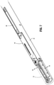
FIG. 1 is a perspective view of an illustrative surgical stapling system in accordance with the principles of this disclosure; -
FIG. 2 is a perspective view, with parts separated, of the surgical stapling system ofFIG. 1 ; -
FIG. 3 is an enlarged, perspective view of a firing wedge of the surgical stapling system ofFIG. 1 ; -
FIGS. 4 and5 are enlarged, perspective views, with parts separated, of the indicated areas of detail shown inFIG. 2 ; -
FIG. 6 is perspective view of the surgical stapling system ofFIG. 1 in relation to a surgical cannula assembly, the surgical stapling system illustrated in a first position with an outer tube of the surgical stapling system shown in phantom for clarity; -
FIG. 7 is an enlarged, perspective view of the indicated area of detail shown inFIG. 6 ; -
FIG. 8 is a perspective view illustrating the surgical stapling system inserted through the surgical cannula assembly ofFIG. 6 and into tissue; -
FIG. 9 is a cross-sectional view of the surgical stapling system ofFIG. 1 as taken along section line 9-9 shown inFIG. 6 ; -
FIG. 10 is an enlarged view of the indicated area of detail shown inFIG. 9 ; and -
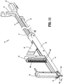
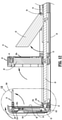
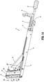
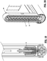
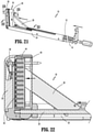
FIGS. 11-24 are progressive views illustrating a firing of the surgical stapling system ofFIG. 1 . - Aspects of the disclosed surgical stapling systems are described in detail with reference to the drawings, in which like reference numerals designate identical or corresponding elements in each of the several views. As commonly known, the term "clinician" refers to a doctor, a nurse, or any other care provider and may include support personnel. Additionally, the term "proximal" refers to the portion of structure that is closer to the clinician and the term "distal" refers to the portion of structure that is farther from the clinician. In addition, directional terms such as front, rear, upper, lower, top, bottom, and the like are used simply for convenience of description and are not intended to limit the disclosure attached hereto.
- In the following description, well-known functions or constructions are not described in detail to avoid obscuring the present disclosure in unnecessary detail.
- Further, although the surgical instrumentation described herein is provided in connection with a manual surgical stapling system for brevity, the disclosed surgical stapling system may be powered and/or or robotically-controlled. For a detailed description of the structure and function of exemplary surgical stapling systems, one or more components of which may be included, or modified for use with the disclosed aspects, reference may be made to
U.S. Patent No. 10,575,849 U.S. Patent No. 10,004,504 U.S. Patent No. 9,675,356 - Briefly, this disclosure details structure and methods for effectuating open and laparoscopic surgical stapling procedures such as a low anterior resection ("LAR"). LAR is a surgery often performed to treat cancer of the rectum where the cancerous portion of the rectum is removed so that the remaining healthy portions of the rectum can be reconnected to the colon with a surgical stapling apparatus. Typically, this procedure is performed as an open procedure. Advantageously, the disclosed surgical stapling system enables a clinician to perform such procedure either openly or laparoscopically. In particular, the disclosed surgical stapling system includes anvil and cartridge assemblies that are movable between a retracted position for insertion through a surgical cannula assembly or trocar, and an extended position in which the anvil and cartridge assemblies extend laterally from the surgical stapling system (e.g., in a guillotine-type stapler arrangement) for clamping, cutting, and stapling tissue therebetween when fired.
- With reference to
FIGS. 1-3 , asurgical stapling system 10 of this disclosure includes ahousing tube 12 supported on anelongated shaft assembly 14 and positioned for relative axial movement between one another.Elongated shaft assembly 14 extends distally to anend effector 16 and defines a longitudinal axis "L" therealong.End effector 16 includes ananvil assembly 30 and acartridge assembly 40 that are moveable between retracted and extended positions for selective advancement thorough, for example, a surgical cannula assembly ortrocar 99 to access a surgical site within tissue "T" (seeFIGS. 6 and8 ).Cartridge assembly 40 houses a plurality ofstaples 42 for forming againstanvil assembly 30 upon a firing ofsurgical stapling system 10.Elongated shaft assembly 14 includes a firingrod 18 for firingstaples 42, a lockingrod 20 for maintaining anvil andcartridge assemblies rod 22 for movingcartridge assembly 40 relative toanvil assembly 30 to clamp tissue therebetween. - Firing
rod 18, lockingrod 20, and clampingrod 22 ofelongated shaft assembly 14 are movably supported within adistal tube 24 on a proximal end portion ofdistal tube 24. - Firing
rod 18 defines aguide channel 18a on a bottom surface thereof that slidably supports firingrod 18 on asupport rib 22a extending axially along clampingrod 22. Firingrod 18 further includes adrive handle 18b on a proximal end portion thereof and apin hole 18c on a distal end portion thereof. - Locking
rod 20 is slidably and rotatably disposed within alumen 22b defined through clampingrod 22. Lockingrod 20 includes agripping handle 20a on a proximal end portion thereof and a threadedtip 20b on a distal end portion thereof. -
Pin hole 18c on the distal end portion of firingrod 18 andpin holes 26a of a firingwedge 26 receive apivot pin 28 therethrough to pivotally couple firingrod 18 and firingwedge 26 together to enable firingwedge 26 to pivot between retracted and extended positions. Firingwedge 26 further defines anangled rod channel 26b through a proximal end portion thereof that receives lockingrod 20 therethrough to lock firingwedge 26 in the extended position thereof. Firingwedge 26 extends distally to afiring tooth 26c. - Clamping
rod 22 definespin channels 22c through raisedtracks 22d of clampingrod 22 that laterally support firingwedge 26 therebetween.Pin channels 22c slidablysupport pivot pin 28 therein to facilitate axial movement of firingrod 18 and firingwedge 26 relative to clampingrod 22. A distal end portion of clampingrod 22 further includespin holes 22e defined therein that accommodatepivot pins 22f for securing the distal end portion of clampingrod 22 tocartridge assembly 40. Pivot pins 22f are coupled totorsion springs 22g that spring bias orurge cartridge assembly 40 in the extended position thereof. -
Distal tube 24 defines an opendistal channel 24a and an openproximal channel 24b therealong. Openproximal channel 24b is raised above opendistal channel 24a and is positioned to enable firingwedge 26 to move between extended and retracted positions relative todistal tube 24.Distal channel 24a is positioned to enable anvil andcartridge assemblies distal tube 24.Distal tube 24 further definespin openings 24c therethrough that receive threaded pivot pins 24d for enablinganvil assembly 30 to pivot relative to a distal end ofdistal tube 24 between the extended and retracted positions thereof.Distal tube 24 further definesinner side channels 24f along an inner surface thereof for slidably receiving clampingrod 22. - Turning now to
FIG. 4 ,cartridge assembly 40 ofend effector 16supports staples 42, apusher 44, and aknife 46.Cartridge assembly 40 includes aproximal housing 48 and adistal housing 49.Staples 42 are disposed in a plurality of rows.Pusher 44 includes a plurality ofpusher bars 44a that align with the plurality of rows ofstaples 42.Pusher 44 includesguide tabs 44b that facilitate alignment withdistal housing 49 and defines aknife slot 44c along a spine thereof for receivingknife 46 therethrough.Pusher 44 also defines analignment pin hole 44d therethrough and knife tab recesses 44f at spaced apart locations alongknife slot 44c.Knife 42 includesproximal tabs 46a that seat in the knife tab recesses 44f ofpusher 44 and adistal cutting edge 46b.Proximal housing 48 defines anelongate wedge channel 48a along a spine thereof for receivingfiring wedge 26 therein and a threadedrod passage 48b for receiving lockingrod 20 therethrough to lockcartridge assembly 40 in the extended position thereof.Proximal housing 48 further includes alignment recesses 48c and mountingapertures 48d that enable alignment and securement ofproximal housing 48 todistal housing 49.Proximal housing 48 also includes analignment pin hole 48e disposed in registration withalignment pin hole 44d ofpusher 44. In addition,proximal housing 48 defines pivot pin holes 48f that receivepivot pins 22f therein to enablecartridge assembly 40 to rotate between the retracted and extended positions thereof.Distal housing 49 includesalignment tabs 49a that are received inalignment recess 48c ofproximal housing 48 to align proximal anddistal housings tabs 49b extend from sidewalls ofdistal housing 49 and are receivable within mountingapertures 48d ofproximal housing 48 to secure proximal anddistal housings guide channels 49c are defined along an inner surface ofdistal housing 49 for receivingguide tabs 44b ofpusher 44 therein. - With brief reference to
FIG. 11 ,distal housing 49 also defines a plurality of rows ofstaple retention slots 49d and aknife slot 49e in a distal face or tissue contacting surface thereof. The plurality of rows ofstaple retention slots 49d are disposed in registration with the plurality ofstaples 42 for enablingstaples 42 to be fired therethrough. - Referring now to
FIG. 5 ,anvil assembly 30 ofend effector 16 includes afirst housing 32, analignment pin assembly 34, aleaf spring 35, aknife stop 36, asecond housing 37, and ananvil 38.First housing 32 ofanvil assembly 30 defines threadedpivot pin holes 32a that receivepivot pins 24d and threaded pivot pins 24d and a threadedrod aperture 32b positioned to receive threadedtip 20b of lockingrod 20.First housing 32 further includes aleaf spring mount 32c and defines aleaf spring channel 32d that facilitate securement ofleaf spring 35 tofirst housing 32.First housing 32 also includes aspring post 32e and defines acoupler pin aperture 32f for supportingalignment pin assembly 34.First housing 32 further includes a knife stop ledge 33g that supports knife stop 36 onfirst housing 32 and definesattachment apertures 32h that facilitate securement of first andsecond housings second housings attachment apertures 32h).First housing 32 also includes apivot pin opening 32i and apivot plate slot 32k (seeFIG. 11 ) that receives apivot pin 32j to couplealignment pin assembly 34 infirst housing 32 and to facilitate pivoting movement ofalignment pin assembly 34 relative tofirst housing 32.First housing 32 further includes anangled slide channel 32m defined therethrough.Second housing 37 includes anangled slide channel 32m in mirrored relation toangled slide channel 32m offirst housing 32. -
Leaf spring 35 includes asnare portion 35a with a snare opening 35b defined therethrough to enablesnare portion 35a to secure toleaf spring mount 32c offirst housing 32.Leaf spring 35 also includes aspring finger 35c that extends fromsnare portion 35a and is received inleaf spring channel 32d offirst housing 32.Spring finger 35c is movable between a flexed position in which a distal end ofspring finger 35c is aligned withsnare portion 35a and parallel to longitudinal axis "L" ofsurgical stapling apparatus 10, and an unflexed position (seeFIG. 5 ) in which the distal end ofspring finger 35 is transverse to snareportion 35a and to longitudinal axis "L" ofsurgical stapling apparatus 10.Leaf spring 35 is positioned to bias or urgeanvil assembly 30 in the extended position thereof whereanvil assembly 30 is transverse to longitudinal axis "L" ofsurgical stapling apparatus 10. -
Alignment pin assembly 34 ofanvil assembly 30 includes apivot plate 342, adrive arm 344, acoupler 345, anelbow 346, acollar 347, analignment pin 348, and acompression spring 349.Pivot plate 342 includes adrive ramp 342a andfirst pin openings 342b that couples to pivotpin 32j and a second pin opening 342c that couples to drivearm 344.Drive arm 344 includespivot plate post 344a on a first end thereof that couples to second pin opening 342c ofpivot plate 342 and a clevis 344b on a second end thereof that receivespivot pin 344c therethrough.Driver arm 344 also includesspring nub 344d to which a first end ofspring 349 couples. A second end ofspring 349 couples to springpost 32e offirst housing 32.Coupler 345 mounts to clevis 344b ofdriver arm 344 and includes side pins 345a that extend therefrom for securing tocoupler pin aperture 32f offirst housing 32 and a corresponding aperture (not shown) defined insecond housing 37.Coupler 345 further defines anelbow slot 345b therebetween that receiveselbow 346 therein forcoupling elbow 346 to clevis 344b ofdriver arm 344 bypin 344c. Elbow 346 defines apin hole 346a on a first end thereof that receivespin 344c therein. Elbow 346 also defines pin holes 346b on a second end thereof for receivingpins 348a therein.Collar 347 couples to elbow 346 andalignment pin 348 to maintainpins 348a in position andsecure alignment pin 348 toelbow 346. First andsecond housings nubs 37a that retainanvil 38 to first andsecond housings nub openings 38a defined throughanvil 38.Anvil 38 further defines a plurality of rows ofstaple forming pockets 38b in a tissue contacting surface thereof. - As shown in
FIGS. 1-24 , in use,surgical stapling apparatus 10 is inserted through asurgical cannula assembly 99 and into tissue "T" with anvil andcartridge assemblies FIG. 8 ). In the retracted position, the anvil andcartridge assemblies cartridge assemblies surgical stapling apparatus 10 for reducing a profile ofsurgical stapling apparatus 10 for easy insertion through a sealed passaged defined throughsurgical cannula assembly 99. With thesurgical stapling apparatus 10 positioned in vivo adjacent a surgical site,housing tube 12 can be retracted proximally so that anvil andcartridge assemblies FIGS. 11 and12 ) byleaf spring 35 andtorsion springs 22g (seeFIG. 2 ), respectively. Lockingrod 20 can be translated axially throughangled rod channel 26b of firingwedge 26 to cause firingwedge 26 to pivot aboutpivot pin 28 toward an extended position thereof relative todistal tube 24. With lockingrod 20 positioned through firingwedge 26, lockingrod 20locks firing wedge 26 in the extended position thereof (e.g., at an acute angle relative to longitudinal axis "L"). Continued distal advancement of lockingrod 20 through threadedrod passage 48b ofcartridge assembly 40, by translation and rotation of lockingrod 20 relative to longitudinal axis "L," lockscartridge assembly 40 in the extended position thereof. Lockingrod 20 is then distally advanced into threaded engagement with threadedrod aperture 32b ofanvil assembly 30, lockinganvil assembly 30 in the extended position thereof. - Continued rotation of locking
rod 20, namely, distally threading threadedtip 20b of lockingrod 20 into threadedrod aperture 32b, causes threadedtip 20b of lockingrod 20 to engagepivot plate 342 ofalignment pin assembly 34 so thatpivot plate 342 rotates downwardly aboutpivot pin 32j drawingdrive arm 344 downwardly against the bias ofcompression spring 349 so thatelbow 346 pivotsalignment pin 348 to an extended position thereof aspivot pin 344c slides downwardly alongangled slide channels 32m of first andsecond housings alignment pin 348 in an extended position and disposed transverse toanvil 38 ofanvil assembly 30, clampingrod 22 can be axially advanced to movecartridge assembly 40 towardanvil assembly 30 to capture tissue therebetween. Finally, firingrod 18 is advanced distally so that firingtooth 26c of firingwedge 26 is received withinelongated wedge channel 48a ofcartridge assembly 40 to drivepusher 44,staples 42, andknife 36 distally for securingstaples 42 to the clamped tissue and for cutting the clamped and stapled tissue. Firingrod 18, lockingrod 20, and clampingrod 22 can be drawn proximally relative todistal tube 24 andhousing tube 12 can be advanced distally relative todistal tube 24 to enable anvil andcartridge assemblies 30, 40 (and firing wedge 26) to move from the extended positions thereof back to the retracted positions thereof. When the components ofsurgical stapling system 10 are disposed in the retracted positions thereof,surgical stapling system 10 can be withdrawn fromsurgical cannula assembly 10. - As those skilled in the art reading this disclosure will appreciate, the various aspects disclosed herein may also be configured to work with robotic surgical systems and what is commonly referred to as "Telesurgery." Such systems employ various robotic elements to assist the clinician and allow remote operation (or partial remote operation) of surgical instrumentation. Various robotic arms, gears, cams, pulleys, electric and mechanical motors, etc. may be employed for this purpose and may be designed with a robotic surgical system to assist the clinician during the course of an operation or treatment. Such robotic systems may include remotely steerable systems, automatically flexible surgical systems, remotely flexible surgical systems, remotely articulating surgical systems, wireless surgical systems, modular or selectively configurable remotely operated surgical systems, etc.
- The robotic surgical systems may be employed with one or more consoles that are next to the operating theater or located in a remote location. In this instance, one team of clinicians may prep the patient for surgery and configure the robotic surgical system with one or more of the instruments disclosed herein while another clinician (or group of clinicians) remotely controls the instruments via the robotic surgical system. As can be appreciated, a highly skilled clinician may perform multiple operations in multiple locations without leaving his/her remote console which can be both economically advantageous and a benefit to the patient or a series of patients. For a detailed description of exemplary medical work stations and/or components thereof, reference may be made to
U.S. Patent Application Publication No. 2012/0116416 , andPCT Application Publication No. WO2016/025132 , the entire contents of each of which are incorporated by reference herein. - As can be appreciated, securement of any of the components of the disclosed systems can be effectuated using known securement techniques such welding, crimping, gluing, fastening, etc.
- Persons skilled in the art will understand that the structures and methods specifically described herein and illustrated in the accompanying figures are non-limiting exemplary aspects, and that the description, disclosure, and figures should be construed merely as exemplary of particular aspects. It is to be understood, therefore, that this disclosure is not limited to the precise aspects described, and that various other changes and modifications may be effectuated by one skilled in the art without departing from the scope or spirit of the disclosure. Additionally, it is envisioned that the elements and features illustrated or described in connection with one exemplary aspect may be combined with the elements and features of another without departing from the scope of this disclosure, and that such modifications and variations are also intended to be included within the scope of this disclosure. Indeed, any combination of any of the disclosed elements and features is within the scope of this disclosure. Accordingly, the subject matter of this disclosure is not to be limited by what has been particularly shown and described.
- The invention is described by the following numbered paragraphs:-
- 1. A transverse surgical stapling system, comprising:
- an elongated shaft assembly;
- a distal tube having a proximal end portion and a distal end portion, the proximal end portion of the distal tube supporting the elongated shaft assembly;
- an anvil assembly supported on the distal end portion of the distal tube; and
- a cartridge assembly supported on the distal tube in movable relation to the anvil assembly, wherein the anvil and cartridge assemblies are movable between retracted and extended positions relative to the distal tube.
- 2. The transverse surgical stapling system of paragraph 1, wherein the cartridge assembly is spring biased toward the extended position thereof by a torsion spring.
- 3. The transverse surgical stapling system of paragraph 2, wherein the anvil assembly is spring biased toward the extended position thereof by a leaf spring.
- 4. The transverse surgical stapling system of paragraph 1, wherein the elongated shaft assembly includes a locking rod that is receivable by the anvil and cartridge assemblies to lock the anvil and cartridge assemblies in the extended positions thereof.
- 5. The transverse surgical stapling system of paragraph 1, wherein the elongated shaft assembly includes a clamping rod that is pivotally coupled to the cartridge assembly, the clamping rod positioned to translate the cartridge assembly relative to the anvil assembly.
- 6. The transverse surgical stapling system of paragraph 1, wherein the elongated shaft assembly includes a firing rod that translates through the distal tube to fire the staples from the cartridge assembly.
- 7. The transverse surgical stapling system of paragraph 6, wherein the firing rod includes a firing wedge pivotally coupled to a distal end portion of the firing rod, the firing wedge positioned to engage the cartridge assembly.
- 8. The transverse surgical stapling system of
paragraph 7, wherein the firing wedge is positioned to pivot between a retracted position within the distal tube and an extended position in which a distal end of the firing wedge extends from the distal tube at an acute angle relative to the distal tube. - 9. The transverse surgical stapling system of paragraph 1, wherein the anvil assembly includes an alignment pin assembly that is positioned to engage the cartridge assembly.
- 10. The transverse surgical stapling system of
paragraph 9, wherein the alignment pin assembly includes an alignment pin that is pivotally coupled to the anvil assembly and positioned to move between a retracted position within the anvil assembly and an extended position in which the alignment pin extends from the anvil assembly transverse to an anvil of the anvil assembly. - 11. A surgical stapling system, comprising:
- a distal tube defining a longitudinal axis;
- an outer tube slidably supported on the distal tube;
- an elongated shaft assembly;
- an anvil assembly; and
- a cartridge assembly supported on the distal tube and movable relative to the anvil assembly, the cartridge assembly movable between a first position aligned with longitudinal axis and a second position transverse to the longitudinal axis.
- 12. The surgical stapling system of paragraph 11, wherein the cartridge assembly is spring biased toward the second position thereof.
- 13. The surgical stapling system of paragraph 11, wherein the outer tube is movable in a proximal direction to enable the cartridge assembly to move from the first position to the second position.
- 14. The surgical stapling system of paragraph 11, wherein the elongated shaft assembly includes a locking rod that is receivable by the cartridge assembly to prevent the cartridge assembly from pivoting relative to the longitudinal axis.
- 15. The surgical stapling system of paragraph 11, wherein the elongated shaft assembly includes a clamping rod that is pivotally coupled to the cartridge assembly, the clamping rod positioned to translate the cartridge assembly relative to the anvil assembly.
- 16. A transverse surgical stapling system, comprising:
- a distal tube defining a longitudinal axis;
- an outer tube slidably supported on the distal tube;
- an elongated shaft assembly;
- a cartridge assembly supporting a plurality of staples; and
- an anvil assembly supported on the distal tube, the anvil assembly pivotable between a retracted position aligned with the distal tube and an extended position in which the anvil assembly extends transverse to the distal tube, wherein in the extended position, the anvil assembly is positioned to form the staples supported in the cartridge assembly.
- 17. The transverse surgical stapling system of
paragraph 16, wherein the elongated shaft assembly includes a firing rod that translates through the distal tube to fire the staples from the cartridge assembly. - 18. The transverse surgical stapling system of
paragraph 17, wherein the firing rod includes a firing wedge pivotally coupled to a distal end portion of the firing rod, the firing wedge positioned to engage the cartridge assembly. - 19. The transverse surgical stapling system of
paragraph 18, wherein the firing wedge is positioned to pivot between a retracted position within the distal tube and an extended position in which a distal end of the firing wedge extends from the distal tube at an acute angle relative to the distal tube. - 20. The transverse surgical stapling system of
paragraph 16, wherein the anvil assembly includes an alignment pin that is pivotally coupled to the anvil assembly and positioned to move between a retracted position and an extended position for selectively engaging the cartridge assembly.
Claims (15)
- A transverse surgical stapling system, comprising:an elongated shaft assembly;a distal tube having a proximal end portion and a distal end portion, the proximal end portion of the distal tube supporting the elongated shaft assembly;
an anvil assembly supported on the distal end portion of the distal tube; anda cartridge assembly supported on the distal tube in movable relation to the anvil assembly, wherein the anvil and cartridge assemblies are movable between retracted and extended positions relative to the distal tube. - The transverse surgical stapling system of claim 1, wherein the cartridge assembly is spring biased toward the extended position thereof by a torsion spring.
- The transverse surgical stapling system of claim 2, wherein the anvil assembly is spring biased toward the extended position thereof by a leaf spring.
- The transverse surgical stapling system of any preceding claim, wherein the elongated shaft assembly includes a locking rod that is receivable by the anvil and cartridge assemblies to lock the anvil and cartridge assemblies in the extended positions thereof.
- The transverse surgical stapling system of any preceding claim, wherein the elongated shaft assembly includes a clamping rod that is pivotally coupled to the cartridge assembly, the clamping rod positioned to translate the cartridge assembly relative to the anvil assembly.
- The transverse surgical stapling system of any preceding claim, wherein the elongated shaft assembly includes a firing rod that translates through the distal tube to fire the staples from the cartridge assembly; preferably wherein the firing rod includes a firing wedge pivotally coupled to a distal end portion of the firing rod, the firing wedge positioned to engage the cartridge assembly.
- The transverse surgical stapling system of claim 6, wherein the firing wedge is positioned to pivot between a retracted position within the distal tube and an extended position in which a distal end of the firing wedge extends from the distal tube at an acute angle relative to the distal tube.
- The transverse surgical stapling system of any preceding claim, wherein the anvil assembly includes an alignment pin assembly that is positioned to engage the cartridge assembly; preferably wherein the alignment pin assembly includes an alignment pin that is pivotally coupled to the anvil assembly and positioned to move between a retracted position within the anvil assembly and an extended position in which the alignment pin extends from the anvil assembly transverse to an anvil of the anvil assembly.
- A surgical stapling system, comprising:a distal tube defining a longitudinal axis;an outer tube slidably supported on the distal tube;an elongated shaft assembly;an anvil assembly; anda cartridge assembly supported on the distal tube and movable relative to the anvil assembly, the cartridge assembly movable between a first position aligned with longitudinal axis and a second position transverse to the longitudinal axis.
- The surgical stapling system of claim 9, wherein the cartridge assembly is spring biased toward the second position thereof; and/or wherein the outer tube is movable in a proximal direction to enable the cartridge assembly to move from the first position to the second position.
- The surgical stapling system of claim 9 or claim 10, wherein the elongated shaft assembly includes a locking rod that is receivable by the cartridge assembly to prevent the cartridge assembly from pivoting relative to the longitudinal axis; and/or wherein the elongated shaft assembly includes a clamping rod that is pivotally coupled to the cartridge assembly, the clamping rod positioned to translate the cartridge assembly relative to the anvil assembly.
- A transverse surgical stapling system, comprising:a distal tube defining a longitudinal axis;an outer tube slidably supported on the distal tube;an elongated shaft assembly;a cartridge assembly supporting a plurality of staples; andan anvil assembly supported on the distal tube, the anvil assembly pivotable between a retracted position aligned with the distal tube and an extended position in which the anvil assembly extends transverse to the distal tube, wherein in the extended position, the anvil assembly is positioned to form the staples supported in the cartridge assembly.
- The transverse surgical stapling system of claim 12, wherein the elongated shaft assembly includes a firing rod that translates through the distal tube to fire the staples from the cartridge assembly; preferably wherein the firing rod includes a firing wedge pivotally coupled to a distal end portion of the firing rod, the firing wedge positioned to engage the cartridge assembly.
- The transverse surgical stapling system of claim 13, wherein the firing wedge is positioned to pivot between a retracted position within the distal tube and an extended position in which a distal end of the firing wedge extends from the distal tube at an acute angle relative to the distal tube.
- The transverse surgical stapling system of any of claims 12 to 14, wherein the anvil assembly includes an alignment pin that is pivotally coupled to the anvil assembly and positioned to move between a retracted position and an extended position for selectively engaging the cartridge assembly.
Applications Claiming Priority (1)
| Application Number | Priority Date | Filing Date | Title |
|---|---|---|---|
| US17/014,421 US11672533B2 (en) | 2020-09-08 | 2020-09-08 | Laparoscopic transverse surgical stapling system |
Publications (1)
| Publication Number | Publication Date |
|---|---|
| EP3964139A1 true EP3964139A1 (en) | 2022-03-09 |
Family
ID=77666272
Family Applications (1)
| Application Number | Title | Priority Date | Filing Date |
|---|---|---|---|
| EP21195367.4A Withdrawn EP3964139A1 (en) | 2020-09-08 | 2021-09-07 | Laparoscopic transverse surgical stapling system |
Country Status (4)
| Country | Link |
|---|---|
| US (1) | US11672533B2 (en) |
| EP (1) | EP3964139A1 (en) |
| JP (1) | JP2022045331A (en) |
| CA (1) | CA3127049A1 (en) |
Families Citing this family (1)
| Publication number | Priority date | Publication date | Assignee | Title |
|---|---|---|---|---|
| US11672533B2 (en) * | 2020-09-08 | 2023-06-13 | Covidien Lp | Laparoscopic transverse surgical stapling system |
Citations (11)
| Publication number | Priority date | Publication date | Assignee | Title |
|---|---|---|---|---|
| EP1722691A1 (en) * | 2004-03-09 | 2006-11-22 | Satiey, Inc. | Devices and methods for placement of partitions within a hollow body organ |
| WO2008141288A1 (en) * | 2007-05-12 | 2008-11-20 | Barosense, Inc. | Devices and methods for stomach partitioning |
| US20120116416A1 (en) | 2010-11-08 | 2012-05-10 | Kuka Laboratories Gmbh | Medical Workstation |
| WO2012125615A2 (en) * | 2011-03-14 | 2012-09-20 | Ethicon Endo-Surgery, Inc. | Surgical stapling instruments |
| EP2574285A1 (en) * | 2006-09-13 | 2013-04-03 | Barosense, Inc. | Endoscopic plication device and method |
| WO2016025132A1 (en) | 2014-08-13 | 2016-02-18 | Covidien Lp | Robotically controlling mechanical advantage gripping |
| US9675356B2 (en) | 2009-05-06 | 2017-06-13 | Covidien Lp | Pin locking mechanism for a surgical instrument |
| US20180168574A1 (en) * | 2014-03-20 | 2018-06-21 | Stepwise Ltd | Convertible surgical tissue staplers and applications using thereof |
| US10004504B2 (en) | 2010-11-02 | 2018-06-26 | Covidien Lp | Adapter for powered surgical devices |
| EP3478189A2 (en) * | 2016-06-29 | 2019-05-08 | Norwegian University of Science and Technology (NTNU) | Surgical stapler and anvil for a surgical stapler |
| US10575849B2 (en) | 2002-04-25 | 2020-03-03 | Covidien Lp | Surgical instruments including MEMS devices |
Family Cites Families (13)
| Publication number | Priority date | Publication date | Assignee | Title |
|---|---|---|---|---|
| US4354628A (en) * | 1980-09-29 | 1982-10-19 | United States Surgical Corporation | Surgical stapler apparatus having pivotally related staple holder and anvil |
| US4665916A (en) * | 1985-08-09 | 1987-05-19 | United States Surgical Corporation | Surgical stapler apparatus |
| US6250532B1 (en) * | 1991-10-18 | 2001-06-26 | United States Surgical Corporation | Surgical stapling apparatus |
| CA2146508C (en) * | 1994-08-25 | 2006-11-14 | Robert H. Schnut | Anvil for circular stapler |
| JP4297603B2 (en) * | 2000-09-19 | 2009-07-15 | 株式会社トップ | Surgical stapler |
| US7303106B2 (en) * | 2002-10-04 | 2007-12-04 | Tyco Healthcare Group Lp | Surgical stapling device with visual indicator |
| AU2006228045B2 (en) * | 2005-10-14 | 2011-11-24 | Covidien Lp | Apparatus for laparoscopic or endoscopic procedures |
| US20090082785A1 (en) * | 2007-09-24 | 2009-03-26 | Milliman Keith L | Anvil Delivery Device Accessory |
| US9386983B2 (en) * | 2008-09-23 | 2016-07-12 | Ethicon Endo-Surgery, Llc | Robotically-controlled motorized surgical instrument |
| US9498222B2 (en) * | 2012-11-29 | 2016-11-22 | Ethicon Endo-Surgery, Llc | Pivoting anvil for surgical circular stapler |
| US10575848B2 (en) * | 2015-12-31 | 2020-03-03 | Ethicon Llc | Surgical stapler with fixed jaw support pin |
| CN111801055B (en) * | 2018-03-02 | 2024-07-05 | 柯惠有限合伙公司 | Surgical suture instruments |
| US11672533B2 (en) * | 2020-09-08 | 2023-06-13 | Covidien Lp | Laparoscopic transverse surgical stapling system |
-
2020
- 2020-09-08 US US17/014,421 patent/US11672533B2/en active Active
-
2021
- 2021-08-09 CA CA3127049A patent/CA3127049A1/en active Pending
- 2021-08-23 JP JP2021135337A patent/JP2022045331A/en active Pending
- 2021-09-07 EP EP21195367.4A patent/EP3964139A1/en not_active Withdrawn
Patent Citations (11)
| Publication number | Priority date | Publication date | Assignee | Title |
|---|---|---|---|---|
| US10575849B2 (en) | 2002-04-25 | 2020-03-03 | Covidien Lp | Surgical instruments including MEMS devices |
| EP1722691A1 (en) * | 2004-03-09 | 2006-11-22 | Satiey, Inc. | Devices and methods for placement of partitions within a hollow body organ |
| EP2574285A1 (en) * | 2006-09-13 | 2013-04-03 | Barosense, Inc. | Endoscopic plication device and method |
| WO2008141288A1 (en) * | 2007-05-12 | 2008-11-20 | Barosense, Inc. | Devices and methods for stomach partitioning |
| US9675356B2 (en) | 2009-05-06 | 2017-06-13 | Covidien Lp | Pin locking mechanism for a surgical instrument |
| US10004504B2 (en) | 2010-11-02 | 2018-06-26 | Covidien Lp | Adapter for powered surgical devices |
| US20120116416A1 (en) | 2010-11-08 | 2012-05-10 | Kuka Laboratories Gmbh | Medical Workstation |
| WO2012125615A2 (en) * | 2011-03-14 | 2012-09-20 | Ethicon Endo-Surgery, Inc. | Surgical stapling instruments |
| US20180168574A1 (en) * | 2014-03-20 | 2018-06-21 | Stepwise Ltd | Convertible surgical tissue staplers and applications using thereof |
| WO2016025132A1 (en) | 2014-08-13 | 2016-02-18 | Covidien Lp | Robotically controlling mechanical advantage gripping |
| EP3478189A2 (en) * | 2016-06-29 | 2019-05-08 | Norwegian University of Science and Technology (NTNU) | Surgical stapler and anvil for a surgical stapler |
Also Published As
| Publication number | Publication date |
|---|---|
| US11672533B2 (en) | 2023-06-13 |
| CA3127049A1 (en) | 2022-03-08 |
| JP2022045331A (en) | 2022-03-18 |
| US20220071629A1 (en) | 2022-03-10 |
Similar Documents
| Publication | Publication Date | Title |
|---|---|---|
| US11864759B2 (en) | Articulated stapling with fire lock | |
| EP3155984B1 (en) | Surgical staple actuating sled with actuation stroke having minimized distance relative to distal staple | |
| EP3155987B1 (en) | Surgical stapler with progressively driven asymmetric alternating staple drivers | |
| EP3155985B1 (en) | Surgical stapler with terminal staple orientation crossing center line | |
| US11141159B2 (en) | Surgical stapler end effector with multi-staple driver crossing center line | |
| EP3363378A1 (en) | Surgical stapler with bent anvil tip, angled staple cartridge tip, and tissue gripping features | |
| BR112015020805B1 (en) | End actuator of a surgical instrument | |
| EP3597122A1 (en) | Surgical stapling end effector component with articulation and asymmetric deformable tip | |
| EP3607892A2 (en) | Surgical stapling end effector component with deformable tip having void | |
| EP3155986A1 (en) | Surgical staple cartridge with varying staple crown width along a curve | |
| EP3607893A2 (en) | Surgical stapling end effector component with deformable tip skewing in multiple planes | |
| EP3607891A2 (en) | Surgical stapling end effector component with deformable tip having thick distal end | |
| EP3964139A1 (en) | Laparoscopic transverse surgical stapling system | |
| US12082811B2 (en) | Surgical stapler anvil jaw with variable firing member slot | |
| EP4362813B1 (en) | Ultra low profile surgical stapling instrument for tissue resections | |
| WO2024187342A1 (en) | Surgical stapling apparatus with pivotable cam inserts, break-away trigger, and tissue gripping structure | |
| CN120959829A (en) | Surgical instruments | |
| CN120959826A (en) | Surgical instruments | |
| WO2026009087A1 (en) | Articulation assembly for a surgical device | |
| CN120959828A (en) | Staple cartridge assembly and surgical instruments |
Legal Events
| Date | Code | Title | Description |
|---|---|---|---|
| PUAI | Public reference made under article 153(3) epc to a published international application that has entered the european phase |
Free format text: ORIGINAL CODE: 0009012 |
|
| STAA | Information on the status of an ep patent application or granted ep patent |
Free format text: STATUS: THE APPLICATION HAS BEEN PUBLISHED |
|
| AK | Designated contracting states |
Kind code of ref document: A1 Designated state(s): AL AT BE BG CH CY CZ DE DK EE ES FI FR GB GR HR HU IE IS IT LI LT LU LV MC MK MT NL NO PL PT RO RS SE SI SK SM TR |
|
| STAA | Information on the status of an ep patent application or granted ep patent |
Free format text: STATUS: REQUEST FOR EXAMINATION WAS MADE |
|
| 17P | Request for examination filed |
Effective date: 20220902 |
|
| RBV | Designated contracting states (corrected) |
Designated state(s): AL AT BE BG CH CY CZ DE DK EE ES FI FR GB GR HR HU IE IS IT LI LT LU LV MC MK MT NL NO PL PT RO RS SE SI SK SM TR |
|
| STAA | Information on the status of an ep patent application or granted ep patent |
Free format text: STATUS: THE APPLICATION HAS BEEN WITHDRAWN |
|
| 18W | Application withdrawn |
Effective date: 20240820 |