EP3964114A1 - Toilet brush holder - Google Patents
Toilet brush holder Download PDFInfo
- Publication number
- EP3964114A1 EP3964114A1 EP21733884.7A EP21733884A EP3964114A1 EP 3964114 A1 EP3964114 A1 EP 3964114A1 EP 21733884 A EP21733884 A EP 21733884A EP 3964114 A1 EP3964114 A1 EP 3964114A1
- Authority
- EP
- European Patent Office
- Prior art keywords
- barrel
- toilet brush
- holder
- holder body
- covers
- Prior art date
- Legal status (The legal status is an assumption and is not a legal conclusion. Google has not performed a legal analysis and makes no representation as to the accuracy of the status listed.)
- Granted
Links
Images



Classifications
-
- A—HUMAN NECESSITIES
- A47—FURNITURE; DOMESTIC ARTICLES OR APPLIANCES; COFFEE MILLS; SPICE MILLS; SUCTION CLEANERS IN GENERAL
- A47K—SANITARY EQUIPMENT; ACCESSORIES THEREFOR, e.g. TOILET ACCESSORIES
- A47K17/00—Other sanitary equipment not covered by the other groups of this subclass ; Holders for toilet brushes
-
- A—HUMAN NECESSITIES
- A47—FURNITURE; DOMESTIC ARTICLES OR APPLIANCES; COFFEE MILLS; SPICE MILLS; SUCTION CLEANERS IN GENERAL
- A47K—SANITARY EQUIPMENT; ACCESSORIES THEREFOR, e.g. TOILET ACCESSORIES
- A47K11/00—Closets without flushing; Urinals without flushing; Chamber pots; Chairs with toilet conveniences or specially adapted for use with toilets
- A47K11/10—Hand tools for cleaning the toilet bowl, seat or cover, e.g. toilet brushes
Definitions
- This disclosure generally relates to the technical field of bathroom products, and more particularly, to a toilet brush holder for placing a toilet brush.
- a toilet brush is a sanitary appliance for cleaning a toilet, which comprises a rod-shaped handle portion and a brush head connected with one end of the handle portion.
- a toilet brush is equipped with a toilet brush holder for use with it.
- the toilet brush isn't used anymore, it is placed in the toilet brush holder such that a convenient storage is achieved.
- a clean and hygienic use is realized.
- the Chinese patent CN202821168U discloses an automatic open-close type toilet brush holder having an inner barrel capable of moving up and down.
- the toilet brush When the toilet brush is placed into the inner barrel, its self-weight propels the inner barrel to move down, so that the inner barrel is covered by a barrel cover hinged with the inner barrel.
- the toilet brush When there is a need to use the toilet brush, the toilet brush is lifted up, and a driving device propels the inner barrel to move up, thus opening the barrel cover such that the toilet brush may be conveniently taken out.
- the aforesaid barrel cover capable of being opened and closed allows the toilet brush to be stored in a closed place after use. Compared with conventional toilet brushes, the aforesaid technical solution achieves a better storage effect.
- the purpose of the present disclosure is to provide a toilet brush holder having covers capable of being automatically opened and closed. According to the present disclosure, a good storage effect is achieved.
- a ventilation hole for communicating the barrel body with the exterior is formed between the barrel covers and the barrel body. The ventilation hole enables the barrel body to be communicated with the outer air, allows the residual water left on the toilet brush to be quickly drained off, and prevents the breeding of bacteria and generation of foul smell.
- a toilet brush holder comprising a holder body and a barrel body, wherein the barrel body is movably sleeved with the holder body, and an elastic member is arranged between the holder body and the barrel body, wherein the upper end of the holder body is hinged with barrel covers which are opened and closed along with the up-down movement of the barrel body, wherein the barrel body comprises an inner barrel arranged in the holder body, and the portion of the holder body below the barrel covers is provided with a ventilation hole, wherein when the toilet brush is placed in the inner barrel, the barrel body overcomes the elastic force of the elastic member and moves down relative to the holder body, thereby propelling the barrel covers such that they are closed at the upper end of the holder body, and allowing the inner barrel to be communicated with the exterior of the holder body through the ventilation hole.
- the holder body further comprises a base and a support arranged on the base, the ventilation hole is formed in the upper portion of the support, the barrel covers are hinged with the upper end of the support, and the inner barrel is sleeved in the support.
- the barrel body comprises an outer shell covering the exterior of the inner barrel.
- the support is arranged between the outer shell and the inner barrel.
- the outer shell is connected with the inner barrel through connecting walls, and the upper portion of the support is provided with avoiding grooves matched with the connecting walls.
- the connecting walls comprise inclined walls inclining upwards from interior to exterior.
- the barrel covers are provided with abutting portions which are in guide fit with the inclined walls.
- the positions of the barrel body corresponding to the inclined walls are provided with stopping portions. The stopping portions interact with the abutting portions to define an opening angle of the barrel covers.
- the lower portion of the support is provided with a through hole.
- the outer shell is higher than the inner barrel, and the ventilation hole is located between the upper end of the support and the upper end of the inner barrel.
- the through hole is located between the upper end of the base and the lower end of the outer shell.
- the elastic member is a spring, and the two ends of the spring respectively abut against the bottom of the inner barrel and the base.
- a positioning rod extending downwards is provided in the inner barrel, and a positioning column extending upwards for allowing the positioning rod to be inserted in is arranged on the base.
- the present disclosure has the following advantages: when the toilet brush is placed in the barrel body, the weight of the toilet brush acts on the barrel body such that the barrel body overcomes the elastic force of the elastic member to move down relative to the holder body. Thus, the barrel covers are propelled to close.
- the toilet brush holder of the present disclosure achieves a good storage effect.
- the ventilation hole is formed in the upper portion of the support below the barrel covers. When the barrel covers are closed at the upper end of the holder body, the ventilation hole is located between the lower end of the barrel covers and the upper end of the barrel body as the barrel body moves down. Thus, the inner barrel is communicated with the exterior of the holder body, and the barrel body is communicated with the outside air.
- the residual water left on the toilet brush may be quickly drained off, so that the breeding of bacteria and generation of foul smell are avoided.
- the weight of the toilet brush no longer acts on the barrel body.
- the barrel body moves up relative to the holder body under the elastic force of the spring such that the barrel covers are propelled to open. In this way, the toilet brush may be conveniently taken out.
- a toilet brush holder comprises a holder body 10 and a barrel body 20, wherein the holder body 10 further comprises a base 11 and a support 12 arranged on the base 11.
- the base 11 is detachably connected with the support 12
- the base 11 is a bowl-shaped rotating body
- the support 12 is a cylinder structure communicated from top to bottom.
- the support 12 is connected to the upper portion of the base 11.
- the base 11 and the support 12 may be integrally formed.
- the barrel body 20 further comprises an inner barrel 21 and an outer shell 22 covering the exterior of the inner barrel 21.
- the support 12 is arranged between the outer shell 22 and the inner barrel 21.
- the outer shell 22 is connected with the inner barrel 21 through connecting walls 201, and the upper portion of the support 12 is provided with avoiding grooves 121 matched with the connecting walls 201.
- the inner barrel 21 of the barrel body 20 is mounted in the support 12, and the connecting walls 201 of the barrel body 20 are assembled in the avoiding grooves 121 of the support 12, thus allowing the barrel body 20 to be movably sleeved with the holder body 10, namely, allowing the barrel body 20 and the holder body 10 to move up and down relative to each other.
- a positioning rod 204 extending downwards may be provided in the inner barrel 21, and a positioning column 111 extending upwards for allowing the positioning rod 204 to be inserted in is arranged on the base 11.
- the outer shell 22 may partially cover the exterior of the inner barrel 21, or the barrel body 20 may not necessarily comprises the outer shell 22.
- An elastic member 40 is arranged between the holder body 10 and the barrel body 20.
- the upper end of the holder body 10 is further hinged with barrel covers 30 which are opened and closed along with the up-down movement of the barrel body 20.
- the elastic member 40 is a spring, and the two ends of the spring respectively abut against the bottom of the inner barrel 21 and the base 11.
- the spring force should be less than the sum of the gravity force borne by the toilet brush and the barrel body 20 but greater than the gravity force borne by the barrel body 20. Namely, when the toilet brush is placed in the barrel body 20, the barrel body 20 moves down such that the spring is in a compressed state, and when the toilet brush is taken out, the spring is reset to propel the barrel body 20 to move up.
- connecting walls 201 are uniformly distributed along the circumferential direction of the support 12, and the positions of the upper end of the support 12 where two opposite connecting walls 201 are located are hinged to the barrel covers 30 through pin shafts. After the two barrel covers 30 are closed, a hole for allowing the handle of the toilet brush to penetrate through is formed in the center of the two barrel covers 30, and the head portion of the toilet brush is integrally arranged in the inner barrel 21 below the barrel cover 30.
- the connecting walls 201 corresponding to the two barrel covers 30 form inclined walls 202 inclining upwards from interior to exterior.
- the barrel covers 30 are provided with abutting portions 301 which are in guide fit with the inclined walls 202, and the positions of the barrel body 20 corresponding to the inclined walls 202 are provided with stopping portions 203.
- the stopping portions 203 interact with the abutting portions 301 to define an opening angle of the barrel covers 30. More specifically, each abutting portion 301 comprises an abutting convex rod 3011 and an abutting convex block 3012, and each stopping portion 203 comprises a stopping groove 2031 and a stopping convex block 2032.
- the barrel covers 30 are further turned over and opened until the abutting convex rods 3011 are inserted into the stopping grooves 2031 and abut against the stopping convex blocks 2032. At this point, the barrel covers are opened to the maximum angle.
- the position of the holder body 10 below the barrel covers 30 is provided with a ventilation hole 50.
- the ventilation hole 50 is formed in the upper portion of the support 12 below the barrel covers 30.
- the ventilation hole 50 is located between the lower end of the barrel covers 30 and the upper end of the barrel body 20 as the barrel body 20 moves down.
- the inner barrel 21 is communicated with the exterior of the holder body 10
- the barrel body 20 is communicated with the outside air.
- the ventilation hole 50 may comprise a plurality of vertical strip-shaped grooves, and may be an integral gap between the two adjacent connecting walls 201.
- the lower portion of the support 12 is provided with a through hole 60.
- the barrel body 20 moves upwards relative to the holder body 10 under the elastic force of the spring such that the through hole 60 communicates the interior of the holder body 10 with the exterior.
- the through hole 60 is located between the upper end of the base 11 and the lower end of the outer shell.
- the lower end of the outer shell 22 is flush with the upper end of the base 11, and when the toilet brush is taken out, the upper end of the outer shell 22 is flush with the upper end of the support 12.
- the through hole 60 facilitates the air circulation inside the holder body 10.
Landscapes
- Health & Medical Sciences (AREA)
- Public Health (AREA)
- Epidemiology (AREA)
- General Health & Medical Sciences (AREA)
- Brushes (AREA)
- Toilet Supplies (AREA)
- Non-Flushing Toilets (AREA)
Abstract
Description
- This disclosure generally relates to the technical field of bathroom products, and more particularly, to a toilet brush holder for placing a toilet brush.
- A toilet brush is a sanitary appliance for cleaning a toilet, which comprises a rod-shaped handle portion and a brush head connected with one end of the handle portion. Normally, a toilet brush is equipped with a toilet brush holder for use with it. When the toilet brush isn't used anymore, it is placed in the toilet brush holder such that a convenient storage is achieved. As the residual water left on the toilet brush is prevented from dripping down on the floor, a clean and hygienic use is realized.
- The Chinese patent
CN202821168U discloses an automatic open-close type toilet brush holder having an inner barrel capable of moving up and down. When the toilet brush is placed into the inner barrel, its self-weight propels the inner barrel to move down, so that the inner barrel is covered by a barrel cover hinged with the inner barrel. When there is a need to use the toilet brush, the toilet brush is lifted up, and a driving device propels the inner barrel to move up, thus opening the barrel cover such that the toilet brush may be conveniently taken out. The aforesaid barrel cover capable of being opened and closed allows the toilet brush to be stored in a closed place after use. Compared with conventional toilet brushes, the aforesaid technical solution achieves a better storage effect. However, the shortcomings of the aforesaid technical solution are: when a wet toilet brush is placed in a closed space, due to the poor ventilation, the breeding of bacteria and generation of foul smell are unavoidable. Thus, it is urgent for those skilled in the art to develop a novel toilet brush holder. - The purpose of the present disclosure is to provide a toilet brush holder having covers capable of being automatically opened and closed. According to the present disclosure, a good storage effect is achieved. When the toilet brush is placed in the barrel body, a ventilation hole for communicating the barrel body with the exterior is formed between the barrel covers and the barrel body. The ventilation hole enables the barrel body to be communicated with the outer air, allows the residual water left on the toilet brush to be quickly drained off, and prevents the breeding of bacteria and generation of foul smell. To achieve the above purpose, the present disclosure adopts the following technical solution: a toilet brush holder comprising a holder body and a barrel body, wherein the barrel body is movably sleeved with the holder body, and an elastic member is arranged between the holder body and the barrel body, wherein the upper end of the holder body is hinged with barrel covers which are opened and closed along with the up-down movement of the barrel body, wherein the barrel body comprises an inner barrel arranged in the holder body, and the portion of the holder body below the barrel covers is provided with a ventilation hole, wherein when the toilet brush is placed in the inner barrel, the barrel body overcomes the elastic force of the elastic member and moves down relative to the holder body, thereby propelling the barrel covers such that they are closed at the upper end of the holder body, and allowing the inner barrel to be communicated with the exterior of the holder body through the ventilation hole.
- In another aspect of the present disclosure, the holder body further comprises a base and a support arranged on the base, the ventilation hole is formed in the upper portion of the support, the barrel covers are hinged with the upper end of the support, and the inner barrel is sleeved in the support.
- In another aspect of the present disclosure, the barrel body comprises an outer shell covering the exterior of the inner barrel. The support is arranged between the outer shell and the inner barrel.
- In another aspect of the present disclosure, the outer shell is connected with the inner barrel through connecting walls, and the upper portion of the support is provided with avoiding grooves matched with the connecting walls.
- In another aspect of the present disclosure, the connecting walls comprise inclined walls inclining upwards from interior to exterior. The barrel covers are provided with abutting portions which are in guide fit with the inclined walls. When the toilet brush is lifted up, the barrel body moves upwards relative to the holder body under the elastic force of the spring, thus enabling the abutting portions to slide along the inclined walls such that the barrels covers are turned over and opened at the upper end of the holder body. In another aspect of the present disclosure, the positions of the barrel body corresponding to the inclined walls are provided with stopping portions. The stopping portions interact with the abutting portions to define an opening angle of the barrel covers.
- In another preferred embodiment, the lower portion of the support is provided with a through hole. When the toilet brush is lifted up, the barrel body moves up relative to the holder body under the elastic force of the spring such that the interior of the holder body is communicated with the exterior through the through hole.
- In another aspect of the present disclosure, the outer shell is higher than the inner barrel, and the ventilation hole is located between the upper end of the support and the upper end of the inner barrel. The through hole is located between the upper end of the base and the lower end of the outer shell. When the toilet brush is placed in the inner barrel, the lower end of the outer shell is flush with the upper end of the base, and when the toilet brush is taken out, the upper end of the outer shell is flush with the upper end of the support.
- In another preferred embodiment, the elastic member is a spring, and the two ends of the spring respectively abut against the bottom of the inner barrel and the base.
- In another preferred embodiment, a positioning rod extending downwards is provided in the inner barrel, and a positioning column extending upwards for allowing the positioning rod to be inserted in is arranged on the base.
- Compared with the prior art, the present disclosure has the following advantages: when the toilet brush is placed in the barrel body, the weight of the toilet brush acts on the barrel body such that the barrel body overcomes the elastic force of the elastic member to move down relative to the holder body. Thus, the barrel covers are propelled to close. The toilet brush holder of the present disclosure achieves a good storage effect. Compared with the prior art, the ventilation hole is formed in the upper portion of the support below the barrel covers. When the barrel covers are closed at the upper end of the holder body, the ventilation hole is located between the lower end of the barrel covers and the upper end of the barrel body as the barrel body moves down. Thus, the inner barrel is communicated with the exterior of the holder body, and the barrel body is communicated with the outside air. By means of the aforesaid design, the residual water left on the toilet brush may be quickly drained off, so that the breeding of bacteria and generation of foul smell are avoided. When the toilet brush is lifted up, the weight of the toilet brush no longer acts on the barrel body. At this point, the barrel body moves up relative to the holder body under the elastic force of the spring such that the barrel covers are propelled to open. In this way, the toilet brush may be conveniently taken out.
-
-
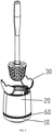
Figure 1 is a conceptual diagram illustrating an example structure of the present disclosure when the barrel covers are closed. -
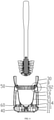
Figure 2 is a conceptual diagram illustrating an example structure of the present disclosure when the barrel covers are opened. -
Figure 3 is a conceptual diagram illustrating an explosive view of the present disclosure. -
Figure 4 is a conceptual diagram illustrating a sectional view of the present disclosure when the barrel covers are closed. -
Figure 5 is a conceptual diagram illustrating an enlarged structure of portion A inFigure 4 . -
Figure 6 is a conceptual diagram illustrating a sectional view of the present disclosure when the barrel covers are opened. -
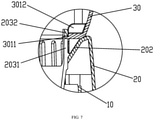
Figure 7 is a conceptual diagram illustrating an enlarged structure of portion B inFigure 6 . - In the Figures: 10-Holder Body, 20-Barrel Body, 30-Barrel Cover, 40-Elastic Member, 50-Ventilation Hole, 60-Through Hole, 11-Base, 111-Positioning Column, 12-Support, 121-Avoiding Groove, 201-Connecting Wall, 202-Inclined Wall, 203-Stopping Portion, 2031-Stopping Convex Groove, 2032-Stopping Convex Block, 204-Positioning Rod, 21-Inner Barrel, 22-Outer Shell, 301-Abutting Portion, 3011-Abutting Convex Rod, 3012-Abutting Convex Block.
- Figures are combined hereinafter to further elaborate the technical solution of the present disclosure.
- As shown in
Figures 1-7 , a toilet brush holder comprises aholder body 10 and abarrel body 20, wherein theholder body 10 further comprises abase 11 and asupport 12 arranged on thebase 11. In this embodiment, thebase 11 is detachably connected with thesupport 12, thebase 11 is a bowl-shaped rotating body, and thesupport 12 is a cylinder structure communicated from top to bottom. Thesupport 12 is connected to the upper portion of thebase 11. Alternatively, thebase 11 and thesupport 12 may be integrally formed. - The
barrel body 20 further comprises aninner barrel 21 and anouter shell 22 covering the exterior of theinner barrel 21. Thesupport 12 is arranged between theouter shell 22 and theinner barrel 21. In this embodiment, theouter shell 22 is connected with theinner barrel 21 through connectingwalls 201, and the upper portion of thesupport 12 is provided with avoidinggrooves 121 matched with theconnecting walls 201. During assembly, theinner barrel 21 of thebarrel body 20 is mounted in thesupport 12, and the connectingwalls 201 of thebarrel body 20 are assembled in the avoidinggrooves 121 of thesupport 12, thus allowing thebarrel body 20 to be movably sleeved with theholder body 10, namely, allowing thebarrel body 20 and theholder body 10 to move up and down relative to each other. To make thebarrel body 20 move stably relative to theholder body 10, apositioning rod 204 extending downwards may be provided in theinner barrel 21, and a positioning column 111 extending upwards for allowing thepositioning rod 204 to be inserted in is arranged on thebase 11. It should be noted that theouter shell 22 may partially cover the exterior of theinner barrel 21, or thebarrel body 20 may not necessarily comprises theouter shell 22. - An
elastic member 40 is arranged between theholder body 10 and thebarrel body 20. The upper end of theholder body 10 is further hinged with barrel covers 30 which are opened and closed along with the up-down movement of thebarrel body 20. More specifically, theelastic member 40 is a spring, and the two ends of the spring respectively abut against the bottom of theinner barrel 21 and thebase 11. The spring force should be less than the sum of the gravity force borne by the toilet brush and thebarrel body 20 but greater than the gravity force borne by thebarrel body 20. Namely, when the toilet brush is placed in thebarrel body 20, thebarrel body 20 moves down such that the spring is in a compressed state, and when the toilet brush is taken out, the spring is reset to propel thebarrel body 20 to move up. In this embodiment, four connectingwalls 201 are uniformly distributed along the circumferential direction of thesupport 12, and the positions of the upper end of thesupport 12 where two opposite connectingwalls 201 are located are hinged to the barrel covers 30 through pin shafts. After the two barrel covers 30 are closed, a hole for allowing the handle of the toilet brush to penetrate through is formed in the center of the two barrel covers 30, and the head portion of the toilet brush is integrally arranged in theinner barrel 21 below thebarrel cover 30. The connectingwalls 201 corresponding to the two barrel covers 30 form inclinedwalls 202 inclining upwards from interior to exterior. The barrel covers 30 are provided with abuttingportions 301 which are in guide fit with theinclined walls 202, and the positions of thebarrel body 20 corresponding to theinclined walls 202 are provided with stoppingportions 203. The stoppingportions 203 interact with the abuttingportions 301 to define an opening angle of the barrel covers 30. More specifically, each abuttingportion 301 comprises an abuttingconvex rod 3011 and an abuttingconvex block 3012, and each stoppingportion 203 comprises a stoppinggroove 2031 and a stoppingconvex block 2032. When the toilet brush is placed in thebarrel body 20, as shown inFigures 5 and7 , thebarrel body 20 moves down, and the stoppingconvex blocks 2032 press against the abuttingconvex rods 3011, thereby pulling the barrel covers such that the barrel covers 30 are inwardly turned over and closed. When the abuttingconvex blocks 3012 of the barrel covers 30 press against the stoppingconvex blocks 2032 of thebarrel body 20, the barrel covers are closed to a maximum angle. When the toilet brush is taken out, as shown inFigures 5 and7 , thebarrel body 20 moves up, and the stoppingconvex blocks 2032 push up against the abutting convex blocks at the starting position, thus enabling the barrel covers 30 to be turned over and opened to a certain angle. As thebarrel body 20 continues moving up, theinclined walls 202 of thebarrel body 20 abut against the abuttingconvex rods 3011 such that the abuttingconvex rods 3011 slide obliquely along theinclined walls 202. In this way, the barrel covers 30 are further turned over and opened until the abuttingconvex rods 3011 are inserted into the stoppinggrooves 2031 and abut against the stoppingconvex blocks 2032. At this point, the barrel covers are opened to the maximum angle. - The position of the
holder body 10 below the barrel covers 30 is provided with aventilation hole 50. In this embodiment, theventilation hole 50 is formed in the upper portion of thesupport 12 below the barrel covers 30. For theouter shell 22 is higher than theinner barrel 21, when the barrel covers 30 are closed at the upper end of theholder body 10, theventilation hole 50 is located between the lower end of the barrel covers 30 and the upper end of thebarrel body 20 as thebarrel body 20 moves down. Thus, theinner barrel 21 is communicated with the exterior of theholder body 10, and thebarrel body 20 is communicated with the outside air. By means of the aforesaid design, the residual water left on the toilet brush may be quickly drained off, so that the breeding of bacteria and generation of foul smell are avoided. It should be noted that theventilation hole 50 may comprise a plurality of vertical strip-shaped grooves, and may be an integral gap between the two adjacent connectingwalls 201. - Preferably, the lower portion of the
support 12 is provided with a throughhole 60. When the toilet brush is lifted up, thebarrel body 20 moves upwards relative to theholder body 10 under the elastic force of the spring such that the throughhole 60 communicates the interior of theholder body 10 with the exterior. The throughhole 60 is located between the upper end of thebase 11 and the lower end of the outer shell. When the toilet brush is placed in theinner barrel 21, the lower end of theouter shell 22 is flush with the upper end of thebase 11, and when the toilet brush is taken out, the upper end of theouter shell 22 is flush with the upper end of thesupport 12. The throughhole 60 facilitates the air circulation inside theholder body 10. - The above are merely preferred embodiments of the present disclosure, and thus all equivalent alterations or modifications made according to the structure, features and principles described in the specification of the present disclosure shall fall into the scope of the present disclosure.
Claims (10)
- A toilet brush holder, comprising:a holder body, anda barrel body, wherein the barrel body is movably sleeved with the holder body, and an elastic member is arranged between the holder body and the barrel body, wherein the upper end of the holder body is hinged with barrel covers which are opened and closed along with the up-down movement of the barrel body, wherein the barrel body comprises an inner barrel arranged in the holder body, and the portion of the holder body below the barrel covers is provided with a ventilation hole, wherein when the toilet brush is placed in the inner barrel, the barrel body overcomes the elastic force of the elastic member and moves down relative to the holder body, thereby propelling the barrel covers such that they are closed at the upper end of the holder body, and allowing the inner barrel to be communicated with the exterior of the holder body through the ventilation hole.
- The toilet brush holder of claim 1, wherein the holder body comprises:a base and a support arranged on the base, wherein the ventilation hole is formed in the upper portion of the support, the barrel covers are hinged with the upper end of the support, and the inner barrel is sleeved in the support.
- The toilet brush holder of claim 1, wherein the barrel body comprises:an outer shell covering the exterior of the inner barrel, wherein the support is arranged between the outer shell and the inner barrel.
- The toilet brush holder of claim 3, wherein the outer shell is connected with the inner barrel through connecting walls, and the upper portion of the support is provided with avoiding grooves matched with the connecting walls.
- The toilet brush holder of claim 4, wherein the connecting walls comprise: inclined walls inclining upwards from interior to exterior, wherein the barrel covers are provided with abutting portions which are in guide fit with the inclined walls, wherein when the toilet brush is lifted up, the barrel body moves upwards relative to the holder body under the elastic force of the spring, thus enabling the abutting portions to slide along the inclined walls such that the barrels covers are turned over and opened at the upper end of the holder body.
- The toilet brush holder of claim 5, wherein the positions of the barrel body corresponding to the inclined walls are provided with stopping portions, wherein the stopping portions interact with the abutting portions to define an opening angle of the barrel covers.
- The toilet brush holder of claim 3, wherein the lower portion of the support is provided with a through hole, wherein when the toilet brush is lifted up, the barrel body moves up relative to the holder body under the elastic force of the spring such that the interior of the holder body is communicated with the exterior through the through hole.
- The toilet brush holder of claim 7, wherein the outer shell is higher than the inner barrel, and the ventilation hole is located between the upper end of the support and the upper end of the inner barrel, wherein the through hole is located between the upper end of the base and the lower end of the outer shell, wherein when the toilet brush is placed in the inner barrel, the lower end of the outer shell is flush with the upper end of the base, and when the toilet brush is taken out, the upper end of the outer shell is flush with the upper end of the support.
- The toilet brush holder of claim 2 or 3, wherein the elastic member is a spring, and the two ends of the spring respectively abut against the bottom of the inner barrel and the base.
- The toilet brush holder of claim 9, wherein a positioning rod extending downwards is provided in the inner barrel, and a positioning column extending upwards for allowing the positioning rod to be inserted in is arranged on the base.
Applications Claiming Priority (2)
| Application Number | Priority Date | Filing Date | Title |
|---|---|---|---|
| CN202021483352.4U CN213551509U (en) | 2020-07-24 | 2020-07-24 | Toilet brush seat |
| PCT/CN2021/076517 WO2022016857A1 (en) | 2020-07-24 | 2021-02-10 | Toilet brush holder |
Publications (4)
| Publication Number | Publication Date |
|---|---|
| EP3964114A1 true EP3964114A1 (en) | 2022-03-09 |
| EP3964114A4 EP3964114A4 (en) | 2022-03-16 |
| EP3964114B1 EP3964114B1 (en) | 2023-10-04 |
| EP3964114C0 EP3964114C0 (en) | 2023-10-04 |
Family
ID=76552000
Family Applications (1)
| Application Number | Title | Priority Date | Filing Date |
|---|---|---|---|
| EP21733884.7A Active EP3964114B1 (en) | 2020-07-24 | 2021-02-10 | Toilet brush holder |
Country Status (4)
| Country | Link |
|---|---|
| EP (1) | EP3964114B1 (en) |
| CN (1) | CN213551509U (en) |
| CA (1) | CA3124363C (en) |
| WO (1) | WO2022016857A1 (en) |
Families Citing this family (3)
| Publication number | Priority date | Publication date | Assignee | Title |
|---|---|---|---|---|
| USD974771S1 (en) * | 2022-06-06 | 2023-01-10 | Shenzhen Ankelong Technology Co., Ltd. | Toilet brush with holder set |
| USD972310S1 (en) * | 2022-07-22 | 2022-12-13 | Qian Wu | Combined toilet brush and holder set |
| CN218572092U (en) * | 2022-08-26 | 2023-03-07 | 宁波世家洁具有限公司 | Cleaning brush and external member thereof |
Family Cites Families (9)
| Publication number | Priority date | Publication date | Assignee | Title |
|---|---|---|---|---|
| US7712609B2 (en) * | 2004-08-17 | 2010-05-11 | Helen Of Troy Limited | Spring biased canister for toilet brush or plunger |
| ES1076388Y (en) * | 2012-02-08 | 2012-05-31 | Juypal Hogar S L | BRUSH HOLDER FOR PORTRAITS |
| CN202821168U (en) | 2012-09-28 | 2013-03-27 | 广东明朗生活用品制造厂有限公司 | Automatic opening-closing type toilet brush |
| CN202891014U (en) * | 2012-10-31 | 2013-04-24 | 广东明朗生活用品制造厂有限公司 | Open-close type toilet brush seat frame |
| CN104013349A (en) * | 2013-05-27 | 2014-09-03 | 昆山赤子坊国际贸易有限公司 | Novel toilet brush support |
| CN205658852U (en) * | 2016-04-22 | 2016-10-26 | 台州市黄岩恒帆模塑有限公司 | Closestool brush holder and composite set thereof |
| CN206371986U (en) * | 2016-08-31 | 2017-08-04 | 管昌国 | A kind of base for toilet brush |
| CN209186531U (en) * | 2018-08-28 | 2019-08-02 | 韩雪山 | A kind of toilet brush storing unit |
| CN210748983U (en) * | 2019-08-23 | 2020-06-16 | 陈仙文 | A drainable toilet brush seat |
-
2020
- 2020-07-24 CN CN202021483352.4U patent/CN213551509U/en active Active
-
2021
- 2021-02-10 WO PCT/CN2021/076517 patent/WO2022016857A1/en not_active Ceased
- 2021-02-10 CA CA3124363A patent/CA3124363C/en active Active
- 2021-02-10 EP EP21733884.7A patent/EP3964114B1/en active Active
Also Published As
| Publication number | Publication date |
|---|---|
| WO2022016857A1 (en) | 2022-01-27 |
| EP3964114B1 (en) | 2023-10-04 |
| CA3124363A1 (en) | 2022-01-24 |
| CN213551509U (en) | 2021-06-29 |
| EP3964114C0 (en) | 2023-10-04 |
| EP3964114A4 (en) | 2022-03-16 |
| CA3124363C (en) | 2023-12-05 |
Similar Documents
| Publication | Publication Date | Title |
|---|---|---|
| US11737620B2 (en) | Toilet brush holder | |
| EP3964114B1 (en) | Toilet brush holder | |
| US7287295B2 (en) | Handle having disposable cleaning head | |
| EP3841945B1 (en) | Water discharge control structure of washing bucket capable of separating clean water from dirty water for washing cleaning tool | |
| US6745427B1 (en) | Brush | |
| CN218572092U (en) | Cleaning brush and external member thereof | |
| AU2022100182A4 (en) | Toilet brush holder | |
| US20110168581A1 (en) | Sanitary bathroom item storage unit | |
| KR101318028B1 (en) | Toilet brush with pedestal | |
| ES2274925T3 (en) | APPARATUS FOR WASHING VEGETABLES AND MOLLUSCS. | |
| US3356429A (en) | Bathroom utility holder | |
| EP1730361A1 (en) | Cleaning device for a water closet | |
| US706407A (en) | Bait-bucket. | |
| CN210540550U (en) | Telescopic tea making device | |
| CN104117997B (en) | A kind of hand-rail type can insert the fruit cutter of toothpick automatically | |
| WO2014007485A1 (en) | Noise-reducing chewing gum container | |
| KR200166208Y1 (en) | Automatic lipstick case | |
| KR20110005817U (en) | Knock-down glue case | |
| CN211559905U (en) | Toilet brush placing device with replaceable brush head | |
| CN215502697U (en) | Disposable toilet brush capable of being thrown | |
| CN214526007U (en) | Pedal flip garbage can convenient for replacing garbage bag | |
| CN215874554U (en) | Cleaning brush cleaning tool capable of realizing automatic cover turning | |
| CN222860457U (en) | Automatic unloading structure for toilet brush | |
| CN222917159U (en) | A discharge structure of a toilet brush | |
| USD1078324S1 (en) | Combined toilet plunger and brush storage container |
Legal Events
| Date | Code | Title | Description |
|---|---|---|---|
| STAA | Information on the status of an ep patent application or granted ep patent |
Free format text: STATUS: UNKNOWN |
|
| STAA | Information on the status of an ep patent application or granted ep patent |
Free format text: STATUS: THE INTERNATIONAL PUBLICATION HAS BEEN MADE |
|
| PUAI | Public reference made under article 153(3) epc to a published international application that has entered the european phase |
Free format text: ORIGINAL CODE: 0009012 |
|
| STAA | Information on the status of an ep patent application or granted ep patent |
Free format text: STATUS: REQUEST FOR EXAMINATION WAS MADE |
|
| 17P | Request for examination filed |
Effective date: 20210916 |
|
| AK | Designated contracting states |
Kind code of ref document: A1 Designated state(s): AL AT BE BG CH CY CZ DE DK EE ES FI FR GB GR HR HU IE IS IT LI LT LU LV MC MK MT NL NO PL PT RO RS SE SI SK SM TR |
|
| A4 | Supplementary search report drawn up and despatched |
Effective date: 20220216 |
|
| RIC1 | Information provided on ipc code assigned before grant |
Ipc: A47K 11/10 20060101ALN20220210BHEP Ipc: A47K 17/00 20060101AFI20220210BHEP |
|
| GRAP | Despatch of communication of intention to grant a patent |
Free format text: ORIGINAL CODE: EPIDOSNIGR1 |
|
| STAA | Information on the status of an ep patent application or granted ep patent |
Free format text: STATUS: GRANT OF PATENT IS INTENDED |
|
| RIC1 | Information provided on ipc code assigned before grant |
Ipc: A47K 11/10 20060101ALN20230523BHEP Ipc: A47K 17/00 20060101AFI20230523BHEP |
|
| RIC1 | Information provided on ipc code assigned before grant |
Ipc: A47K 11/10 20060101ALN20230607BHEP Ipc: A47K 17/00 20060101AFI20230607BHEP |
|
| INTG | Intention to grant announced |
Effective date: 20230622 |
|
| GRAS | Grant fee paid |
Free format text: ORIGINAL CODE: EPIDOSNIGR3 |
|
| GRAA | (expected) grant |
Free format text: ORIGINAL CODE: 0009210 |
|
| STAA | Information on the status of an ep patent application or granted ep patent |
Free format text: STATUS: THE PATENT HAS BEEN GRANTED |
|
| AK | Designated contracting states |
Kind code of ref document: B1 Designated state(s): AL AT BE BG CH CY CZ DE DK EE ES FI FR GB GR HR HU IE IS IT LI LT LU LV MC MK MT NL NO PL PT RO RS SE SI SK SM TR |
|
| DAV | Request for validation of the european patent (deleted) | ||
| DAX | Request for extension of the european patent (deleted) | ||
| REG | Reference to a national code |
Ref country code: GB Ref legal event code: FG4D |
|
| REG | Reference to a national code |
Ref country code: CH Ref legal event code: EP |
|
| REG | Reference to a national code |
Ref country code: IE Ref legal event code: FG4D |
|
| REG | Reference to a national code |
Ref country code: DE Ref legal event code: R096 Ref document number: 602021005667 Country of ref document: DE |
|
| U01 | Request for unitary effect filed |
Effective date: 20231106 |
|
| U07 | Unitary effect registered |
Designated state(s): AT BE BG DE DK EE FI FR IT LT LU LV MT NL PT SE SI Effective date: 20231110 |
|
| U20 | Renewal fee for the european patent with unitary effect paid |
Year of fee payment: 4 Effective date: 20240109 |
|
| PG25 | Lapsed in a contracting state [announced via postgrant information from national office to epo] |
Ref country code: GR Free format text: LAPSE BECAUSE OF FAILURE TO SUBMIT A TRANSLATION OF THE DESCRIPTION OR TO PAY THE FEE WITHIN THE PRESCRIBED TIME-LIMIT Effective date: 20240105 |
|
| PG25 | Lapsed in a contracting state [announced via postgrant information from national office to epo] |
Ref country code: IS Free format text: LAPSE BECAUSE OF FAILURE TO SUBMIT A TRANSLATION OF THE DESCRIPTION OR TO PAY THE FEE WITHIN THE PRESCRIBED TIME-LIMIT Effective date: 20240204 |
|
| PG25 | Lapsed in a contracting state [announced via postgrant information from national office to epo] |
Ref country code: ES Free format text: LAPSE BECAUSE OF FAILURE TO SUBMIT A TRANSLATION OF THE DESCRIPTION OR TO PAY THE FEE WITHIN THE PRESCRIBED TIME-LIMIT Effective date: 20231004 |
|
| PG25 | Lapsed in a contracting state [announced via postgrant information from national office to epo] |
Ref country code: IS Free format text: LAPSE BECAUSE OF FAILURE TO SUBMIT A TRANSLATION OF THE DESCRIPTION OR TO PAY THE FEE WITHIN THE PRESCRIBED TIME-LIMIT Effective date: 20240204 Ref country code: GR Free format text: LAPSE BECAUSE OF FAILURE TO SUBMIT A TRANSLATION OF THE DESCRIPTION OR TO PAY THE FEE WITHIN THE PRESCRIBED TIME-LIMIT Effective date: 20240105 Ref country code: ES Free format text: LAPSE BECAUSE OF FAILURE TO SUBMIT A TRANSLATION OF THE DESCRIPTION OR TO PAY THE FEE WITHIN THE PRESCRIBED TIME-LIMIT Effective date: 20231004 |
|
| PG25 | Lapsed in a contracting state [announced via postgrant information from national office to epo] |
Ref country code: RS Free format text: LAPSE BECAUSE OF FAILURE TO SUBMIT A TRANSLATION OF THE DESCRIPTION OR TO PAY THE FEE WITHIN THE PRESCRIBED TIME-LIMIT Effective date: 20231004 Ref country code: PL Free format text: LAPSE BECAUSE OF FAILURE TO SUBMIT A TRANSLATION OF THE DESCRIPTION OR TO PAY THE FEE WITHIN THE PRESCRIBED TIME-LIMIT Effective date: 20231004 Ref country code: NO Free format text: LAPSE BECAUSE OF FAILURE TO SUBMIT A TRANSLATION OF THE DESCRIPTION OR TO PAY THE FEE WITHIN THE PRESCRIBED TIME-LIMIT Effective date: 20240104 Ref country code: HR Free format text: LAPSE BECAUSE OF FAILURE TO SUBMIT A TRANSLATION OF THE DESCRIPTION OR TO PAY THE FEE WITHIN THE PRESCRIBED TIME-LIMIT Effective date: 20231004 |
|
| REG | Reference to a national code |
Ref country code: DE Ref legal event code: R097 Ref document number: 602021005667 Country of ref document: DE |
|
| PG25 | Lapsed in a contracting state [announced via postgrant information from national office to epo] |
Ref country code: CZ Free format text: LAPSE BECAUSE OF FAILURE TO SUBMIT A TRANSLATION OF THE DESCRIPTION OR TO PAY THE FEE WITHIN THE PRESCRIBED TIME-LIMIT Effective date: 20231004 |
|
| PG25 | Lapsed in a contracting state [announced via postgrant information from national office to epo] |
Ref country code: SK Free format text: LAPSE BECAUSE OF FAILURE TO SUBMIT A TRANSLATION OF THE DESCRIPTION OR TO PAY THE FEE WITHIN THE PRESCRIBED TIME-LIMIT Effective date: 20231004 |
|
| PG25 | Lapsed in a contracting state [announced via postgrant information from national office to epo] |
Ref country code: SM Free format text: LAPSE BECAUSE OF FAILURE TO SUBMIT A TRANSLATION OF THE DESCRIPTION OR TO PAY THE FEE WITHIN THE PRESCRIBED TIME-LIMIT Effective date: 20231004 Ref country code: SK Free format text: LAPSE BECAUSE OF FAILURE TO SUBMIT A TRANSLATION OF THE DESCRIPTION OR TO PAY THE FEE WITHIN THE PRESCRIBED TIME-LIMIT Effective date: 20231004 Ref country code: RO Free format text: LAPSE BECAUSE OF FAILURE TO SUBMIT A TRANSLATION OF THE DESCRIPTION OR TO PAY THE FEE WITHIN THE PRESCRIBED TIME-LIMIT Effective date: 20231004 Ref country code: CZ Free format text: LAPSE BECAUSE OF FAILURE TO SUBMIT A TRANSLATION OF THE DESCRIPTION OR TO PAY THE FEE WITHIN THE PRESCRIBED TIME-LIMIT Effective date: 20231004 |
|
| PLBE | No opposition filed within time limit |
Free format text: ORIGINAL CODE: 0009261 |
|
| STAA | Information on the status of an ep patent application or granted ep patent |
Free format text: STATUS: NO OPPOSITION FILED WITHIN TIME LIMIT |
|
| 26N | No opposition filed |
Effective date: 20240705 |
|
| PG25 | Lapsed in a contracting state [announced via postgrant information from national office to epo] |
Ref country code: MC Free format text: LAPSE BECAUSE OF FAILURE TO SUBMIT A TRANSLATION OF THE DESCRIPTION OR TO PAY THE FEE WITHIN THE PRESCRIBED TIME-LIMIT Effective date: 20231004 |
|
| REG | Reference to a national code |
Ref country code: CH Ref legal event code: PL |
|
| PG25 | Lapsed in a contracting state [announced via postgrant information from national office to epo] |
Ref country code: CH Free format text: LAPSE BECAUSE OF NON-PAYMENT OF DUE FEES Effective date: 20240229 |
|
| PG25 | Lapsed in a contracting state [announced via postgrant information from national office to epo] |
Ref country code: CH Free format text: LAPSE BECAUSE OF NON-PAYMENT OF DUE FEES Effective date: 20240229 |
|
| PG25 | Lapsed in a contracting state [announced via postgrant information from national office to epo] |
Ref country code: IE Free format text: LAPSE BECAUSE OF NON-PAYMENT OF DUE FEES Effective date: 20240210 |
|
| PG25 | Lapsed in a contracting state [announced via postgrant information from national office to epo] |
Ref country code: IE Free format text: LAPSE BECAUSE OF NON-PAYMENT OF DUE FEES Effective date: 20240210 |
|
| U20 | Renewal fee for the european patent with unitary effect paid |
Year of fee payment: 5 Effective date: 20250210 |
|
| PG25 | Lapsed in a contracting state [announced via postgrant information from national office to epo] |
Ref country code: CY Free format text: LAPSE BECAUSE OF FAILURE TO SUBMIT A TRANSLATION OF THE DESCRIPTION OR TO PAY THE FEE WITHIN THE PRESCRIBED TIME-LIMIT; INVALID AB INITIO Effective date: 20210210 |
|
| PG25 | Lapsed in a contracting state [announced via postgrant information from national office to epo] |
Ref country code: HU Free format text: LAPSE BECAUSE OF FAILURE TO SUBMIT A TRANSLATION OF THE DESCRIPTION OR TO PAY THE FEE WITHIN THE PRESCRIBED TIME-LIMIT; INVALID AB INITIO Effective date: 20210210 |
|
| U1N | Appointed representative for the unitary patent procedure changed after the registration of the unitary effect |
Representative=s name: MURGITROYD & COMPANY; GB |
|
| PG25 | Lapsed in a contracting state [announced via postgrant information from national office to epo] |
Ref country code: TR Free format text: LAPSE BECAUSE OF FAILURE TO SUBMIT A TRANSLATION OF THE DESCRIPTION OR TO PAY THE FEE WITHIN THE PRESCRIBED TIME-LIMIT Effective date: 20231004 |
|
| U20 | Renewal fee for the european patent with unitary effect paid |
Year of fee payment: 6 Effective date: 20260130 |
|
| PGFP | Annual fee paid to national office [announced via postgrant information from national office to epo] |
Ref country code: GB Payment date: 20260130 Year of fee payment: 6 |