EP3963416B1 - A method for a lane change of a plurality of vehicles - Google Patents
A method for a lane change of a plurality of vehicles Download PDFInfo
- Publication number
- EP3963416B1 EP3963416B1 EP19720582.6A EP19720582A EP3963416B1 EP 3963416 B1 EP3963416 B1 EP 3963416B1 EP 19720582 A EP19720582 A EP 19720582A EP 3963416 B1 EP3963416 B1 EP 3963416B1
- Authority
- EP
- European Patent Office
- Prior art keywords
- vehicle
- lane
- vehicles
- change
- determination
- Prior art date
- Legal status (The legal status is an assumption and is not a legal conclusion. Google has not performed a legal analysis and makes no representation as to the accuracy of the status listed.)
- Active
Links
Images




Classifications
-
- B—PERFORMING OPERATIONS; TRANSPORTING
- B60—VEHICLES IN GENERAL
- B60W—CONJOINT CONTROL OF VEHICLE SUB-UNITS OF DIFFERENT TYPE OR DIFFERENT FUNCTION; CONTROL SYSTEMS SPECIALLY ADAPTED FOR HYBRID VEHICLES; ROAD VEHICLE DRIVE CONTROL SYSTEMS FOR PURPOSES NOT RELATED TO THE CONTROL OF A PARTICULAR SUB-UNIT
- B60W30/00—Purposes of road vehicle drive control systems not related to the control of a particular sub-unit, e.g. of systems using conjoint control of vehicle sub-units
- B60W30/18—Propelling the vehicle
- B60W30/18009—Propelling the vehicle related to particular drive situations
- B60W30/18163—Lane change; Overtaking manoeuvres
-
- B—PERFORMING OPERATIONS; TRANSPORTING
- B60—VEHICLES IN GENERAL
- B60W—CONJOINT CONTROL OF VEHICLE SUB-UNITS OF DIFFERENT TYPE OR DIFFERENT FUNCTION; CONTROL SYSTEMS SPECIALLY ADAPTED FOR HYBRID VEHICLES; ROAD VEHICLE DRIVE CONTROL SYSTEMS FOR PURPOSES NOT RELATED TO THE CONTROL OF A PARTICULAR SUB-UNIT
- B60W60/00—Drive control systems specially adapted for autonomous road vehicles
- B60W60/001—Planning or execution of driving tasks
- B60W60/0015—Planning or execution of driving tasks specially adapted for safety
-
- G—PHYSICS
- G05—CONTROLLING; REGULATING
- G05D—SYSTEMS FOR CONTROLLING OR REGULATING NON-ELECTRIC VARIABLES
- G05D1/00—Control of position, course, altitude or attitude of land, water, air or space vehicles, e.g. using automatic pilots
- G05D1/02—Control of position or course in two dimensions
- G05D1/021—Control of position or course in two dimensions specially adapted to land vehicles
- G05D1/0287—Control of position or course in two dimensions specially adapted to land vehicles involving a plurality of land vehicles, e.g. fleet or convoy travelling
- G05D1/0291—Fleet control
- G05D1/0293—Convoy travelling
-
- G—PHYSICS
- G05—CONTROLLING; REGULATING
- G05D—SYSTEMS FOR CONTROLLING OR REGULATING NON-ELECTRIC VARIABLES
- G05D1/00—Control of position, course, altitude or attitude of land, water, air or space vehicles, e.g. using automatic pilots
- G05D1/60—Intended control result
- G05D1/69—Coordinated control of the position or course of two or more vehicles
- G05D1/695—Coordinated control of the position or course of two or more vehicles for maintaining a fixed relative position of the vehicles, e.g. for convoy travelling or formation flight
-
- G—PHYSICS
- G08—SIGNALLING
- G08G—TRAFFIC CONTROL SYSTEMS
- G08G1/00—Traffic control systems for road vehicles
- G08G1/09—Arrangements for giving variable traffic instructions
- G08G1/0962—Arrangements for giving variable traffic instructions having an indicator mounted inside the vehicle, e.g. giving voice messages
- G08G1/0967—Systems involving transmission of highway information, e.g. weather, speed limits
- G08G1/096708—Systems involving transmission of highway information, e.g. weather, speed limits where the received information might be used to generate an automatic action on the vehicle control
- G08G1/096725—Systems involving transmission of highway information, e.g. weather, speed limits where the received information might be used to generate an automatic action on the vehicle control where the received information generates an automatic action on the vehicle control
-
- G—PHYSICS
- G08—SIGNALLING
- G08G—TRAFFIC CONTROL SYSTEMS
- G08G1/00—Traffic control systems for road vehicles
- G08G1/09—Arrangements for giving variable traffic instructions
- G08G1/0962—Arrangements for giving variable traffic instructions having an indicator mounted inside the vehicle, e.g. giving voice messages
- G08G1/0967—Systems involving transmission of highway information, e.g. weather, speed limits
- G08G1/096766—Systems involving transmission of highway information, e.g. weather, speed limits where the system is characterised by the origin of the information transmission
- G08G1/096791—Systems involving transmission of highway information, e.g. weather, speed limits where the system is characterised by the origin of the information transmission where the origin of the information is another vehicle
-
- G—PHYSICS
- G08—SIGNALLING
- G08G—TRAFFIC CONTROL SYSTEMS
- G08G1/00—Traffic control systems for road vehicles
- G08G1/16—Anti-collision systems
- G08G1/161—Decentralised systems, e.g. inter-vehicle communication
- G08G1/163—Decentralised systems, e.g. inter-vehicle communication involving continuous checking
-
- G—PHYSICS
- G08—SIGNALLING
- G08G—TRAFFIC CONTROL SYSTEMS
- G08G1/00—Traffic control systems for road vehicles
- G08G1/16—Anti-collision systems
- G08G1/167—Driving aids for lane monitoring, lane changing, e.g. blind spot detection
-
- G—PHYSICS
- G08—SIGNALLING
- G08G—TRAFFIC CONTROL SYSTEMS
- G08G1/00—Traffic control systems for road vehicles
- G08G1/22—Platooning, i.e. convoy of communicating vehicles
-
- H—ELECTRICITY
- H04—ELECTRIC COMMUNICATION TECHNIQUE
- H04W—WIRELESS COMMUNICATION NETWORKS
- H04W4/00—Services specially adapted for wireless communication networks; Facilities therefor
- H04W4/30—Services specially adapted for particular environments, situations or purposes
- H04W4/40—Services specially adapted for particular environments, situations or purposes for vehicles, e.g. vehicle-to-pedestrians [V2P]
- H04W4/46—Services specially adapted for particular environments, situations or purposes for vehicles, e.g. vehicle-to-pedestrians [V2P] for vehicle-to-vehicle communication [V2V]
-
- B—PERFORMING OPERATIONS; TRANSPORTING
- B60—VEHICLES IN GENERAL
- B60W—CONJOINT CONTROL OF VEHICLE SUB-UNITS OF DIFFERENT TYPE OR DIFFERENT FUNCTION; CONTROL SYSTEMS SPECIALLY ADAPTED FOR HYBRID VEHICLES; ROAD VEHICLE DRIVE CONTROL SYSTEMS FOR PURPOSES NOT RELATED TO THE CONTROL OF A PARTICULAR SUB-UNIT
- B60W2300/00—Indexing codes relating to the type of vehicle
- B60W2300/14—Tractor-trailers, i.e. combinations of a towing vehicle and one or more towed vehicles, e.g. caravans; Road trains
- B60W2300/145—Semi-trailers
-
- B—PERFORMING OPERATIONS; TRANSPORTING
- B60—VEHICLES IN GENERAL
- B60W—CONJOINT CONTROL OF VEHICLE SUB-UNITS OF DIFFERENT TYPE OR DIFFERENT FUNCTION; CONTROL SYSTEMS SPECIALLY ADAPTED FOR HYBRID VEHICLES; ROAD VEHICLE DRIVE CONTROL SYSTEMS FOR PURPOSES NOT RELATED TO THE CONTROL OF A PARTICULAR SUB-UNIT
- B60W2556/00—Input parameters relating to data
- B60W2556/45—External transmission of data to or from the vehicle
- B60W2556/50—External transmission of data to or from the vehicle of positioning data, e.g. GPS [Global Positioning System] data
-
- B—PERFORMING OPERATIONS; TRANSPORTING
- B60—VEHICLES IN GENERAL
- B60W—CONJOINT CONTROL OF VEHICLE SUB-UNITS OF DIFFERENT TYPE OR DIFFERENT FUNCTION; CONTROL SYSTEMS SPECIALLY ADAPTED FOR HYBRID VEHICLES; ROAD VEHICLE DRIVE CONTROL SYSTEMS FOR PURPOSES NOT RELATED TO THE CONTROL OF A PARTICULAR SUB-UNIT
- B60W2556/00—Input parameters relating to data
- B60W2556/45—External transmission of data to or from the vehicle
- B60W2556/65—Data transmitted between vehicles
Definitions
- the invention relates to a method for a lane change of a plurality of vehicles on a multi-lane road.
- the invention also relates to a computer program, a computer readable medium, a control unit or a group of control units, and a vehicle.
- the invention can be applied in heavy-duty vehicles, such as trucks and buses. Although the invention will be described with respect to trucks, the invention is not restricted to this particular vehicle, but may also be used in other vehicles such as cars.
- This information is used in the control to keep the desired distance between each vehicle and the immediately preceding vehicle and to handle events such as hard braking.
- the V2V communication enables keeping short distances safely since the V2V information is transferred much faster and is more accurate than data from on-board sensors such as radar sensors, laser sensors or cameras.
- DE102017206987A1 relates to a method for determining a collective maneuver of at least two vehicles, which includes joint maneuvers by the at least two vehicles.
- DE102016216634A1 relates to a method for arranging or changing the arrangement of a motor vehicle in a convoy of vehicles, which comprises a plurality of convoy vehicles, which drive one behind the other in a longitudinally and transversely guided manner, at least in a partially automated manner.
- the method provides a lane change process for the vehicles travelling in a row.
- the vehicles may travel in a row, one after the other.
- the vehicles may cooperate for the lane change process of the invention.
- Controlling the vehicles to travel in a row in the first lane comprises controlling the vehicles to form a string of platooning vehicles with vehicle-to-vehicle (V2V) communication based control.
- V2V vehicle-to-vehicle
- data is sent from the second vehicle to the first vehicle, the data being provided for the first determination, or representing a result of the first determination.
- the vehicles may have V2V communication equipment, allowing them to share the data based on sensor information on surrounding static, or dynamic objects. If the sent data is provided for the first determination, the first vehicle may make the first determination based on the data. If the second vehicle makes, based on the signals from the second vehicle sensor, the first determination, the data sent to the first vehicle may represent the result of the first determination. In some embodiments however, a driver of the second vehicle may, by suitable means, give a signal to a driver of the first vehicle, indicating a result of the first determination.
- the step of controlling the first vehicle, so as to change lane to the second lane is made in dependence on the first determination.
- the lane change of the first vehicle may be made in a safe way.
- the need for a costly configuration of sensors on the first vehicle may be avoided.
- a long range rear looking sensor may be needed to spot non-cooperating vehicles approaching from the rear.
- a rear looking sensor may need to be mounted on a trailer or a semitrailer, and this is a problem when such units are not sold together with the towing vehicle.
- the second vehicle sensor may cover an area in the second lane, where a non-cooperating vehicle, moving at a relatively high speed, can reach the area needed for the first vehicle to change lane.
- the second determination is made also by means of at least one sensor on the second vehicle.
- the second determination may be made by means of one or more sensors on the second vehicle.
- data based on signals from the sensor on the first vehicle, is sent from the first vehicle to the second vehicle, the data being provided for the second determination, or representing a result of the second determination.
- the step of controlling the second vehicle, so as to change lane to the second lane is made in dependence on the second determination.
- the sensor of the first vehicle may be a forward looking sensor. Thereby, a redundant coverage is provided by the first vehicle sensor, and the second vehicle sensor. This will substantially contribute to the second vehicle lane change to be a safe maneuver.
- the second vehicle may be positioned in a first position in the second lane
- the third vehicle may be positioned in a second position in the first lane, the first position being less advanced in the direction of travel than the second position, and thereafter, the third vehicle may be controlled so as to change lane to the second lane, and thereby move in front of the second vehicle.
- the first vehicle may be positioned in a first position in the second lane
- the third vehicle may be positioned in a second position in the first lane, the first position being less advanced in the direction of travel than the second position
- the third vehicle may be controlled so as to change lane to the second lane, and thereby move in between the first and second vehicles.
- the first and second vehicles may be controlled so that there is a distance between the first and second vehicles, to allow the third vehicle to enter in between the first and second vehicles.
- the determination is made also by means of at least one sensor on the second vehicle.
- the determination is made, by means of the sensors on the first and second vehicles, whereby a sensor redundancy is provided.
- the respective control unit 102, 202, 303 is arranged to receive signals from the respective sensors 111, 112, 211, 212, 311, 312.
- the sensors 111, 112, 211, 212, 311, 312 could be LIDAR sensors or cameras.
- any of the vehicles could be provided with two or more forward sensors.
- one of the forward sensors could be a radar sensor
- another forward sensor could be a camera.
- any of the vehicles could be provided with four or more sideways sensors. Thereby, for each of the right side and the left side of the vehicle, one of the sideways sensors could be a radar sensor, and another sideways sensor could be a camera.
- the second lane L2 is adjacent to the first lane L1. In this example, the second lane L2 is to the left of the first lane L1, as seen in the direction of travel of the vehicles.
- the first determination is made by means of one of the sideways sensors 112, 212, 312 on each of the vehicles 1, 2, 3. Further, data, based on signals from the sideways sensor 212 on the second vehicle 2, is sent from the second vehicle to the first vehicle 1. Also, data, based on signals from the sideways sensor 312 on the third vehicle 3, is sent from the third vehicle to the first vehicle 1. The data is sent by means of the V2V communication equipment. The data sent represents the sensor signals. The data is provided for the first determination S2.
- the second determination S5 is made also by means of the sideways sensor 212 ( fig. 1 ) of the second vehicle 2.
- the second vehicle sideways sensor 212 covers an area A2 including a stretch of the second lane L2 which extends along the length of the second vehicle 2. Thereby, a redundant coverage is provided by the first vehicle forward sensor 111, and the second vehicle sideways sensor 212.
- the second vehicle Based on the data being based on signals from the first vehicle forward sensor 111, and the signals from the second vehicle sideways sensor 212, the second vehicle makes the determination S5, whether it is safe for the second vehicle 2 to change lane to the second lane L2.
- the second vehicle 2 is controlled S6 so as to change lane to the second lane L2, and thereby move in front of the first vehicle 1.
- the first and second vehicles 1, 2 move backwards relative to the third vehicle 3.
- the second vehicle 2 ends up being positioned in a first position P1 in relation to the third vehicle 3.
- the third vehicle 3 is thereby in a second position P2 in relation to the second vehicle 2.
- the first position P1 is less advanced in the direction of travel M than the second position P2.
Landscapes
- Engineering & Computer Science (AREA)
- Physics & Mathematics (AREA)
- General Physics & Mathematics (AREA)
- Automation & Control Theory (AREA)
- Radar, Positioning & Navigation (AREA)
- Aviation & Aerospace Engineering (AREA)
- Remote Sensing (AREA)
- Transportation (AREA)
- Mechanical Engineering (AREA)
- Atmospheric Sciences (AREA)
- Life Sciences & Earth Sciences (AREA)
- Computer Networks & Wireless Communication (AREA)
- Signal Processing (AREA)
- Human Computer Interaction (AREA)
- Traffic Control Systems (AREA)
- Control Of Driving Devices And Active Controlling Of Vehicle (AREA)
Description
- The invention relates to a method for a lane change of a plurality of vehicles on a multi-lane road. The invention also relates to a computer program, a computer readable medium, a control unit or a group of control units, and a vehicle.
- The invention can be applied in heavy-duty vehicles, such as trucks and buses. Although the invention will be described with respect to trucks, the invention is not restricted to this particular vehicle, but may also be used in other vehicles such as cars.
- In platooning, e.g. by means of Cooperative Adaptive Cruise Control (CACC), vehicle convoys may be driven with short distances between the vehicles. Thereby the vehicles form what is herein referred to as a string. To achieve this with a high safety, a control unit of each vehicle receives information from surrounding vehicles over a wireless communication channel, so called Vehicle-to-Vehicle (V2V) communication. For example, such shared information may include brake pressure, engine torque, engine RPM, accelerator pedal position, engine manifold pressure, vehicle speed, radar/lidar data, and/or vehicle capacities.
- This information is used in the control to keep the desired distance between each vehicle and the immediately preceding vehicle and to handle events such as hard braking. The V2V communication enables keeping short distances safely since the V2V information is transferred much faster and is more accurate than data from on-board sensors such as radar sensors, laser sensors or cameras.
- It is understood that the V2V communication may involve controlling the velocity and/or acceleration of a vehicle in the string in dependence on the signals received from another vehicle in the string. The string may be formed of a row of vehicles, one following another.
- Benefits with platooning, e.g. by CACC, include increased fuel efficiency, provided by a reduced air-drag due to short distances between vehicles, and provided by improved vehicle control due to more accurate information about the preceding vehicle.
- A further benefit is an improved traffic flow due to the small delay of the V2V data. For example, the traffic flow may be improved by reducing or eliminating the so called rubber-band effect between vehicles. Such an effect may appear due to the delay of a detection by a vehicle of a deceleration of a preceding vehicle, causing a stronger deceleration of the detecting vehicle, upon which a delay of a detection by a following vehicle of the stronger deceleration causing an even stronger deceleration of the following vehicle, and so on. In CACC based control the rubber band effect will be considerably reduced due to the decreased delay, and due to a detecting vehicle being able to take into account signals from vehicles in front of the immediately preceding vehicle.
- Yet another benefit with CACC and platooning is an improved driver comfort since CACC allows less aggressive vehicle control compared to systems using on-board sensors exclusively.
- Notwithstanding said benefits, there is still room for improvement of known CACC and other platooning strategies. Improvements are needed for controlling platooning vehicles in a lane change maneuver.
-
US2017011633 describes a vehicle control system for changing the lane of platooning vehicles. The control system controls the platoon vehicles so that the last vehicle of the platoon enters the other lane first, and then the vehicles of the platoon enter the other lane ahead of the last vehicle. However, a problem thereby is that a vehicle, not participating in the platoon, which may have overtaken the last vehicle before its lane change, and may remain in the other lane, next to another platooning vehicle, thereby preventing the other platooning vehicle from changing lane. - The document with reference Nycc: "PACELINING", 31 March 2015 (2015-03-31), XP055655946 relates to pace lines which are those neat single file lines you see in Tour de France. The technique is a way to cover a lot of distance with less energy expended by the riders in the group. In pacelining, the group of riders travels in a line, one close behind the other. For example, the document describes a so called circular paceline where riders cycle in two parallel lines and circulate, each taking an immediate turn once coming to the front.
-
DE102017206987A1 relates to a method for determining a collective maneuver of at least two vehicles, which includes joint maneuvers by the at least two vehicles. -
WO2018035145A1 relates to systems and methods for vehicle platoon reconfiguration. For example, it teaches one example of vehicle movement following a change of a lead vehicle in a platoon. The former lead vehicle (in a first position) moves from the lead position in the platoon to a second or third position, respectively, in an example platoon with three vehicles. The new lead vehicle moves from either the second or third position, respectively, to the lead position. After the new lead vehicle and the former lead vehicle are in position, the platoon vehicles continue moving forward and resume steady state operation. -
DE102016216634A1 relates to a method for arranging or changing the arrangement of a motor vehicle in a convoy of vehicles, which comprises a plurality of convoy vehicles, which drive one behind the other in a longitudinally and transversely guided manner, at least in a partially automated manner. - An object of the invention is to facilitate a lane change maneuver of vehicles travelling in a row, for example as platooning vehicles.
- The object is reached by a method according to
claim 1. Thus, the invention provides a method for a lane change of a plurality of vehicles on a multi-lane road, the method comprising - controlling the vehicles to travel in a row in a first lane, with a first of the vehicles in front of a second of the vehicles,
- thereafter controlling the first vehicle so as to change lane to a second lane adjacent to the first lane,
- thereafter positioning the first vehicle in a first position in the second lane, and positioning the second vehicle in a second position in the first lane, the first position being less advanced in the direction of travel than the second position, and
- thereafter controlling the second vehicle so as to change lane to the second lane, and thereby move in front of the first vehicle.
- Thus, the method provides a lane change process for the vehicles travelling in a row. The vehicles may travel in a row, one after the other. Preferably, there is no vehicle between the first and second vehicles as they are controlled to travel in a row in the first lane. The vehicles may cooperate for the lane change process of the invention. Controlling the vehicles to travel in a row in the first lane, comprises controlling the vehicles to form a string of platooning vehicles with vehicle-to-vehicle (V2V) communication based control. Thereby, embodiments of the method provides a lane change of a vehicle platoon comprising a plurality of vehicles platooning on a multi-lane road. The vehicles may form a string comprising a plurality of vehicles platooning by means of V2V communication. The string may comprise two, three, or more vehicles. Thus, in some embodiments, the first vehicle may travel in front of one or more vehicles in addition to the second vehicle.
- It should be noted that the first and second vehicles preferably comprises means for automatic lateral vehicle control. Such means may for example comprise an adaption of a control unit in each of the first and second vehicles, to control a steering function of the respective vehicle. Such a control may be based on, for example, signals from one or more cameras on the respective vehicle, and a function to determine a lateral position based on, for example, road markings. Thereby, the lane change process may be performed automatically. In some embodiments, the vehicles may be fully autonomous. Such autonomous vehicles may be provided with control units which are arranged to cooperate for the lane change process. The control units may be arranged to communicate by means of V2V communication. However, in other embodiments, the lane change process may be performed by means of human drivers of the vehicles.
- The invention comprises positioning the first vehicle in a first position in the second lane, and positioning the second vehicle in a second position in the first lane, the first position being less advanced in the direction of travel than the second position. It should be noted that the first and second positions may be relative positions. Preferably, in the first and second positions, a front end of the first vehicle is, in the direction of travel, behind a rear end of the second vehicle. For reaching the first position, the first vehicle may, after having changed lane, move backwards relative to the second vehicle. The invention allows thus for the first vehicle changing lane first, and the second vehicle then overtaking the first vehicle. In other words, the lane change process may involve the first vehicle pushing backwards relative to the remaining of the cooperating vehicles, which are yet to change lane. This will allow for the creation of an empty area necessary for the second vehicle to make the lane change. In other words, the risk that a vehicle, not participating in the cooperation, is in the second lane, next to the second vehicle, thereby preventing the lane change of the second vehicle, is reduced. This is particularly useful in dense traffic.
- In addition, the lane change provides a change of the order of the cooperating vehicles. This is beneficial where there is an agreement, e.g. based on fuel saving ambitions, to alternate the lead vehicle.
- The invention provides an advantageous lane change assistance and/or automation. In case of platooning vehicles, lane change process may be programmed as a sequence of steps to form an automatic lane change process of the platoon.
- The method comprises, during the step of controlling the vehicles to travel in a row in the first lane, making a first determination, by means of at least one sensor on the second vehicle, whether it is safe for the first vehicle to change lane to the second lane. Thus, one or more sensors on the second vehicle, may be used to determine whether it is safe for the first vehicle to change lane to the second lane. This is advantageous, since the second vehicle may have a better "view" than the first vehicle, e.g. of non-cooperating vehicles overtaking the platoon in the second lane.
- Preferably, data, based on signals from the sensor on the second vehicle, is sent from the second vehicle to the first vehicle, the data being provided for the first determination, or representing a result of the first determination. Thereby, an advantageous information sharing is provided. The vehicles may have V2V communication equipment, allowing them to share the data based on sensor information on surrounding static, or dynamic objects. If the sent data is provided for the first determination, the first vehicle may make the first determination based on the data. If the second vehicle makes, based on the signals from the second vehicle sensor, the first determination, the data sent to the first vehicle may represent the result of the first determination. In some embodiments however, a driver of the second vehicle may, by suitable means, give a signal to a driver of the first vehicle, indicating a result of the first determination.
- The step of controlling the first vehicle, so as to change lane to the second lane, is made in dependence on the first determination. Thereby, the lane change of the first vehicle may be made in a safe way. In addition, the need for a costly configuration of sensors on the first vehicle, may be avoided. For example, in prior art, a long range rear looking sensor may be needed to spot non-cooperating vehicles approaching from the rear. In the case of a truck, such a rear looking sensor may need to be mounted on a trailer or a semitrailer, and this is a problem when such units are not sold together with the towing vehicle. The second vehicle sensor, may cover an area in the second lane, where a non-cooperating vehicle, moving at a relatively high speed, can reach the area needed for the first vehicle to change lane.
- Preferably, the method comprises making, with the first and second vehicles in the first and second positions, respectively, a second determination, by means of at least one sensor on the first vehicle, whether it is safe for the second vehicle to change lane to the second lane. The second determination may be made by means of one or more sensors on the first vehicle. Thereby, an improvement of known solutions may be provided in that the sensor on the first vehicle, which may be a forward looking sensor, may have a better view of the second lane, than a sensor of the second vehicle.
- Preferably, the second determination is made also by means of at least one sensor on the second vehicle. Thereby, the second determination may be made by means of one or more sensors on the second vehicle. Preferably data, based on signals from the sensor on the first vehicle, is sent from the first vehicle to the second vehicle, the data being provided for the second determination, or representing a result of the second determination. Preferably, the step of controlling the second vehicle, so as to change lane to the second lane, is made in dependence on the second determination. The sensor of the first vehicle may be a forward looking sensor. Thereby, a redundant coverage is provided by the first vehicle sensor, and the second vehicle sensor. This will substantially contribute to the second vehicle lane change to be a safe maneuver.
- Embodiments of the method may allow for reliably detecting, in a second lane area for the second vehicle lane change, a non-cooperating vehicle driving slower that the cooperating vehicles, or entering the area from a third lane.
- Embodiments of the invention may involve more than two vehicles. Thereby, controlling the vehicles to travel in a row in the first lane, may comprise controlling a third of the vehicles to travel behind the second vehicle. The method may thereby comprise, after controlling the second vehicle so as to change lane to the second lane, positioning the first vehicle, or the second vehicle, in a first position in the second lane, and positioning the third vehicle in a second position in the first lane, the first position being less advanced in the direction of travel than the second position. The third vehicle may thereafter be controlled so as to change lane to the second lane, to thereby move in between the first and second vehicles, or in front of the second vehicle
- Thus, the second vehicle may be positioned in a first position in the second lane, and the third vehicle may be positioned in a second position in the first lane, the first position being less advanced in the direction of travel than the second position, and thereafter, the third vehicle may be controlled so as to change lane to the second lane, and thereby move in front of the second vehicle. Alternatively, the first vehicle may be positioned in a first position in the second lane, and the third vehicle may be positioned in a second position in the first lane, the first position being less advanced in the direction of travel than the second position, and thereafter, the third vehicle may be controlled so as to change lane to the second lane, and thereby move in between the first and second vehicles. For this, the first and second vehicles may be controlled so that there is a distance between the first and second vehicles, to allow the third vehicle to enter in between the first and second vehicles.
- Such embodiments may provide an effective and safe changing lane for three or more cooperating vehicles.
- An aspect of the invention provides a method for a lane change of a vehicle travelling on a multi-lane road, the method comprising
- positioning a first vehicle in a first position in a second lane, and positioning a second vehicle in a second position in a first lane adjacent to the second lane, the first position being less advanced in the direction of travel than the second position,
- making, with the first and second vehicles in the first and second positions, respectively, a determination, by means of at least one sensor on the first vehicle, whether it is safe for the second vehicle to change lane to the second lane, and,
- controlling, in dependence on the determination, the second vehicle so as to change lane to the second lane, and thereby move in front of the first vehicle.
- Thereby, the first vehicle sensor will assist the lane change of the second vehicle, since it may have a better view of the second lane, compared to a sensor of the second vehicle. It should be noted that in such an aspect, it is necessary for the first vehicle to have reached the second lane with a lane change from the first lane. Even if the first vehicle reached the second lane by changing from the first lane, it is not necessary for the first vehicle to have been ahead of the second vehicle in the first lane. The first vehicle could have been behind the second vehicle in the first lane, before changing to the second lane.
- Preferably, the determination is made also by means of at least one sensor on the second vehicle. Thereby, with the first and second vehicles in the first and second positions, respectively, the determination is made, by means of the sensors on the first and second vehicles, whereby a sensor redundancy is provided.
- The object is also reached with a computer program according to claim 10, a computer readable medium according to claim 11, a control unit or a group of control units according to claim 12, or a vehicle according to claim 13.
- Further advantages and advantageous features of the invention are disclosed in the following description and in the dependent claims.
- With reference to the appended drawings, below follows a more detailed description of embodiments of the invention cited as examples.
- In the drawings:
-
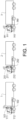
Fig. 1 is a side view of vehicles in a string of platooning vehicles. -
Fig. 2 is a diagram depicting steps in a method for a lane change of the vehicles infig. 1 , according to an embodiment of the invention. -
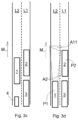
Fig. 3a -fig. 3f are top views of the vehicles infig. 1 , showing vehicle positions in during the execution of the method infig. 2 . -
Fig. 4 is a diagram depicting steps in a method for a lane change of the vehicles infig. 1 , according to a more general embodiment of the invention. -
Fig. 1 shows what is herein referred to as afirst vehicle 1, asecond vehicle 2, and athird vehicle 3. In this example, thevehicles - Each of the
vehicles equipment control unit - By means of this equipment for CACC, each of the
vehicles vehicles - The
vehicles first vehicle 1, is a receiving vehicle controlled to be at a relatively short distance from a transmitting vehicle immediately in front of the respective receiving vehicle. - It should be noted that the invention is applicable also to strings made up of less, or more than three vehicles. The invention is equally applicable to strings made up of two vehicles.
- The vehicle control system of the respective receiving vehicle controls brakes and a drivetrain of the receiving vehicle based on the wireless signals received from the respective transmitting vehicle.
- It should be noted that in some embodiments, the vehicle control system of the respective receiving vehicle may control brakes and a drivetrain of the receiving vehicle based on the wireless signals received from a vehicle in front of the vehicle immediately in front of the respective receiving vehicle, e.g. from the vehicle at the front of the string, as an alternative to or in addition to wireless signals received from the vehicle immediately in front of the respective receiving vehicle.
- The
vehicles respective vehicle - Each
vehicle forward sensor forward sensor respective vehicle forward sensor forward sensor - Each
vehicle sideways sensors fig. 1 . Thesideways sensors sideways sensors - The
respective control unit respective sensors sensors - With reference to
fig. 2 andfig. 3a-3f , a method for a lane change of the platoon infig. 1 , according to an embodiment of the invention will be described. - The method comprises controlling S1 the platooning
vehicles fig. 3a . The direction of movement, or travel, of the vehicles is indicated with an arrow M. Thereby thefirst vehicle 1 is in front of thesecond vehicle 2. - A first determination is made S2. It is determined whether it is safe for the
first vehicle 1 to change lane to a second lane L2. The second lane L2 is adjacent to the first lane L1. In this example, the second lane L2 is to the left of the first lane L1, as seen in the direction of travel of the vehicles. - The first determination is made by means of one of the
sideways sensors vehicles sideways sensor 212 on thesecond vehicle 2, is sent from the second vehicle to thefirst vehicle 1. Also, data, based on signals from thesideways sensor 312 on thethird vehicle 3, is sent from the third vehicle to thefirst vehicle 1. The data is sent by means of the V2V communication equipment. The data sent represents the sensor signals. The data is provided for the first determination S2. - It should be noted that the first determination S2 may be based on signals from further sensors, such as rearward facing sensor on one or more of the vehicles.
- It is determined S2 that it is safe for the first vehicle to change lane, if the signals from the sensors indicate that there are no obstacles in the second lane, e.g. in the form of one or
more vehicles 4, in an area covered by the sensors. As indicated infig. 3a , in this embodiment, thesideways sensor sideways sensors - If it is determined S2 that it is safe for the first vehicle to change lane, the
first vehicle 1 is controlled S3 so as to change lane to the second lane L2, as depicted infig. 3b . Thus, this lane change is made in dependence on the first determination. The lane change of the first vehicle may be performed by means of an automatic control of the first vehicle wheel steering, based on sensor signals indicating the relative positions of road markings, etc., as is known per se, and will not be described closer here. - As depicted in
fig. 3c and fig. 3d , after having changed lane, thefirst vehicle 1 is moves backwards relative to the other vehicles. Thereby, thefirst vehicle 1 ends up being positioned S4 in a first position P1 in relation to thesecond vehicle 2. Further thesecond vehicle 2 is thereby in a second position P2 in relation to thefirst vehicle 1. The first position P1 is less advanced in the direction of travel M than the second position P2. Preferably, thefirst vehicle 1 does not, in the first position P1, overlap, in the direction of travel M, the second vehicle. Preferably, the first vehicle is in the first position P1 at a relatively short distance from the second vehicle. For example, in the first and second positions P1, P2 of the first and second vehicles, respectively, there is, in the direction of travel M, a separation time gap between the first andsecond vehicles second vehicle 2, to the time of passing of a front end of thefirst vehicle 1. Thereby, it may be secured that a stretch of the second lane L2 is free for the second vehicle to move to the second lane L2. - Preferably, in the first position P1 of the
first vehicle 1, there is, in the direction of travel M of the vehicles, at least a partial overlap between thefirst vehicle 1 and thethird vehicle 3. Thereby, thethird vehicle 3 may prevent any further vehicle from overtaking thefirst vehicle 1, in the first lane L1, and then moving to the second lane L2, in front of the first vehicle. - As exemplified in
fig. 3d , in the first position P1, the forward sensor 111 (fig. 1 ) of thefirst vehicle 1 covers an area A11, which includes a stretch of the second lane which is next to thesecond vehicle 2. A second determination is made S5, by means of the firstvehicle forward sensor 111, whether it is safe for thesecond vehicle 2 to change lane to the second lane L2. Data, being based on, e.g. representing, signals from the firstvehicle forward sensor 111, is sent from thefirst vehicle 1 to thesecond vehicle 2. The data is sent by means of the V2V communication equipment. - The second determination S5 is made also by means of the sideways sensor 212 (
fig. 1 ) of thesecond vehicle 2. The second vehicle sidewayssensor 212 covers an area A2 including a stretch of the second lane L2 which extends along the length of thesecond vehicle 2. Thereby, a redundant coverage is provided by the firstvehicle forward sensor 111, and the second vehicle sidewayssensor 212. Based on the data being based on signals from the firstvehicle forward sensor 111, and the signals from the second vehicle sidewayssensor 212, the second vehicle makes the determination S5, whether it is safe for thesecond vehicle 2 to change lane to the second lane L2. - If it is determined S5 that it is safe for the
second vehicle 2 to change lane to the second lane L2, thesecond vehicle 2 is controlled S6 so as to change lane to the second lane L2, and thereby move in front of thefirst vehicle 1. - As depicted in
fig. 3e , similarly to what has been described above, after the lane change of thesecond vehicle 2, the first andsecond vehicles third vehicle 3. Thereby, thesecond vehicle 2 ends up being positioned in a first position P1 in relation to thethird vehicle 3. Further, thethird vehicle 3 is thereby in a second position P2 in relation to thesecond vehicle 2. The first position P1 is less advanced in the direction of travel M than the second position P2. Thereby, it may be secured that a stretch of the second lane L2 is free for thethird vehicle 3 to move to the second lane L2. - As exemplified in
fig. 3e , similarly to what has been described above, in the first position P1, the forward sensor 211 (fig. 1 ) of thesecond vehicle 2 covers an area A21, which includes a stretch of the second lane L2 which is next to thethird vehicle 3. A determination is made, by means of the secondvehicle forward sensor 211, whether it is safe for thethird vehicle 3 to change lane to the second lane L2. The determination is made also by means of the sideways sensor 312 (fig. 1 ) of thethird vehicle 3. The third vehicle sidewayssensor 312 covers an area A3 including a stretch of the second lane L2 which extends along the length of thethird vehicle 3. Thereby, a redundant coverage is provided by the secondvehicle forward sensor 211, and the third vehicle sidewayssensor 312. - As depicted in
fig. 3f , if it is determined that it is safe for thethird vehicle 3 to change lane to the second lane L2, thethird vehicle 3 is controlled so as to change lane to the second lane L2, and thereby move in front of thesecond vehicle 2. - Thereby, all vehicles 1-3 have changed lane. The
last vehicle 3 before the lane change becomes the first vehicle after the lane change. - It should be noted that alternatives to the process described above with reference to
fig. 1 -fig. 3 are possible, For example, once thesecond vehicle 3 has changed lane, thethird vehicle 3 can change lane so as to move in between the first andsecond vehicles third vehicle 3 to change lane to the second lane L2, may be made by means of the firstvehicle forward sensor 111. -
Fig. 4 depicts steps in a more general example which may be useful for understanding the invention. In a method for a lane change of a plurality of vehicles on a multi-lane road, the following steps are performed: The vehicles are controlled S1 to travel in a row in a first lane, with a first of the vehicles in front of a second of the vehicles. Thereafter, the first vehicle is controlled S3 so as to change lane to a second lane adjacent to the first lane. Thereafter, the first vehicle is positioned S4 in a first position in the second lane, and the second vehicle is positioned in a second position in the first lane, the first position being less advanced in the direction of travel M than the second position. Thereafter, the second vehicle is controlled S6 so as to change lane to the second lane, and thereby move in front of the first vehicle. - It is to be understood that the present invention is not limited to the embodiments described above and illustrated in the drawings; rather, the skilled person will recognize that many changes and modifications may be made within the scope of the appended claims.
Claims (13)
- A method for a lane change of a plurality of vehicles on a multi-lane road, the method comprising- controlling the vehicles to travel in a row in a first lane (L1), with a first of the vehicles (1) in front of a second of the vehicles (2),- thereafter controlling the first vehicle (1) so as to change lane to a second lane (L2) adjacent to the first lane (L1),- thereafter positioning the first vehicle (1) in a first position (P1) in the second lane (L2), and positioning the second vehicle (2) in a second position (P2) in the first lane (L1), the first position (P1) being less advanced in the direction of travel (M) than the second position (P2), and- thereafter controlling the second vehicle (2) so as to change lane to the second lane (L2), and thereby move in front of the first vehicle (1), characterized in that controlling the vehicles to travel in a row in the first lane, comprises controlling the vehicles to form a string of platooning vehicles with vehicle-to-vehicle (V2V) communication based control, and during the step of controlling the vehicles to travel in a row in the first lane (L1), making a first determination, by means of at least one sensor on the second vehicle (2), whether it is safe for the first vehicle (1) to change lane to the second lane (L2), and in that the step of controlling the first vehicle (1), so as to change lane to the second lane (L2), is made in dependence on the first determination.
- A method according to claim 1, characterized in that data, based on signals from the sensor on the second vehicle (2), is sent from the second vehicle to the first vehicle (1), the data being provided for the first determination, or representing a result of the first determination.
- A method according to any one of the preceding claims, characterized by making, with the first and second vehicles (1, 2) in the first and second positions (P1, P2), respectively, a second determination, by means of at least one sensor on the first vehicle (1), whether it is safe for the second vehicle (2) to change lane to the second lane (L2).
- A method according to claim 3, characterized in that the second determination is made also by means of at least one sensor on the second vehicle (2).
- A method according to any one of claims 3-4, characterized in that data, based on signals from the sensor on the first vehicle (1), is sent from the first vehicle to the second vehicle (2), the data being provided for the second determination, or representing a result of the second determination.
- A method according to any one of claims 3-5, characterized in that the step of controlling the second vehicle (2), so as to change lane to the second lane (L2), is made in dependence on the second determination.
- A method according to any one of the preceding claims, characterized in that controlling the vehicles to travel in a row in the first lane (L1), comprises controlling a third of the vehicles (3) to travel behind the second vehicle (2), the method comprising, after controlling the second vehicle (2) so as to change lane to the second lane (L2), positioning the first vehicle (1), or the second vehicle (2), in a first position in the second lane (L2), and positioning the third vehicle (3) in a second position in the first lane (L1), the first position being less advanced in the direction of travel than the second position, and, thereafter, controlling the third vehicle (3) so as to change lane to the second lane (L2), to thereby move in between the first and second vehicles (1, 2), or in front of the second vehicle (2).
- A method for a lane change of a vehicle travelling on a multi-lane road, the method comprising- positioning a first vehicle (1) in a first position (P1) in a second lane (L2), and positioning a second vehicle (2) in a second position (P2) in a first lane (L1) adjacent to the second lane (L2), the first position (P1) being less advanced in the direction of travel than the second position (P2), characterized in that- making, with the first and second vehicles (1, 2) in the first and second positions (P1, P2), respectively, a determination, by means of at least one sensor on the first vehicle (1), whether it is safe for the second vehicle (2) to change lane to the second lane (L2), and,- controlling, in dependence on the determination, the second vehicle (2) so as to change lane to the second lane (L2), and thereby move in front of the first vehicle (1).
- A method according to claim 8, characterized in that the determination is made also by means of at least one sensor on the second vehicle (2).
- A computer program comprising program code means for performing the steps of any of claims 1-9 when said program is run on a computer.
- A computer readable medium carrying a computer program comprising program code means for performing the steps of any of claims 1-9 when said program product is run on a computer.
- A control unit or a group of control units configured to perform the steps of the method according to any of claims 1-9.
- A vehicle comprising a control unit according to claim 12.
Applications Claiming Priority (1)
| Application Number | Priority Date | Filing Date | Title |
|---|---|---|---|
| PCT/EP2019/060935 WO2020221420A1 (en) | 2019-04-29 | 2019-04-29 | A method for a lane change of a plurality of vehicles |
Publications (2)
| Publication Number | Publication Date |
|---|---|
| EP3963416A1 EP3963416A1 (en) | 2022-03-09 |
| EP3963416B1 true EP3963416B1 (en) | 2024-07-03 |
Family
ID=66334493
Family Applications (1)
| Application Number | Title | Priority Date | Filing Date |
|---|---|---|---|
| EP19720582.6A Active EP3963416B1 (en) | 2019-04-29 | 2019-04-29 | A method for a lane change of a plurality of vehicles |
Country Status (4)
| Country | Link |
|---|---|
| US (1) | US12139144B2 (en) |
| EP (1) | EP3963416B1 (en) |
| JP (1) | JP2022539287A (en) |
| WO (1) | WO2020221420A1 (en) |
Families Citing this family (7)
| Publication number | Priority date | Publication date | Assignee | Title |
|---|---|---|---|---|
| US11994867B2 (en) * | 2020-04-02 | 2024-05-28 | Paravit, LLC | Syncing operational data for heavy equipment |
| DE102020002993B4 (en) * | 2020-05-19 | 2022-11-10 | Mercedes-Benz Group AG | Method for supporting a vehicle |
| CN112416004B (en) * | 2020-11-19 | 2021-12-14 | 腾讯科技(深圳)有限公司 | A control method, device, vehicle and related equipment based on automatic driving |
| JP7645779B2 (en) * | 2021-11-30 | 2025-03-14 | 本田技研工業株式会社 | MOBILE BODY CONTROL DEVICE, MOBILE BODY CONTROL METHOD, AND PROGRAM |
| CN114348001B (en) * | 2022-01-06 | 2024-04-26 | 腾讯科技(深圳)有限公司 | Traffic simulation method, device, equipment and storage medium |
| EP4406798A1 (en) * | 2023-01-30 | 2024-07-31 | Volvo Truck Corporation | Situation based under speed for a predictive cruise control |
| CN117681878B (en) * | 2024-02-04 | 2024-04-16 | 西南交通大学 | Intelligent network-connected automobile collaborative lane changing method based on formation perception |
Family Cites Families (7)
| Publication number | Priority date | Publication date | Assignee | Title |
|---|---|---|---|---|
| US10115314B2 (en) * | 2015-07-08 | 2018-10-30 | Magna Electronics Inc. | Lane change system for platoon of vehicles |
| WO2018035145A1 (en) | 2016-08-19 | 2018-02-22 | Pcms Holdings, Inc. | Method for changing the lead vehicle of a vehicle platoon |
| DE102016216634A1 (en) * | 2016-09-02 | 2018-03-08 | Audi Ag | Method for classifying a motor vehicle in a vehicle convoy |
| DE102017206987A1 (en) * | 2017-04-26 | 2018-10-31 | Bayerische Motoren Werke Aktiengesellschaft | The method, computer program product, computer-readable medium, controller and vehicle include the controller for determining a collective maneuver of at least two vehicles |
| JP2019028733A (en) * | 2017-07-31 | 2019-02-21 | 日野自動車株式会社 | Convoy travel system |
| JP6926957B2 (en) * | 2017-11-02 | 2021-08-25 | トヨタ自動車株式会社 | Lane change support device |
| KR20190075221A (en) * | 2017-12-21 | 2019-07-01 | 현대자동차주식회사 | Vehicle, and control method for the same |
-
2019
- 2019-04-29 WO PCT/EP2019/060935 patent/WO2020221420A1/en not_active Ceased
- 2019-04-29 JP JP2021564383A patent/JP2022539287A/en active Pending
- 2019-04-29 US US17/594,444 patent/US12139144B2/en active Active
- 2019-04-29 EP EP19720582.6A patent/EP3963416B1/en active Active
Also Published As
| Publication number | Publication date |
|---|---|
| JP2022539287A (en) | 2022-09-08 |
| WO2020221420A1 (en) | 2020-11-05 |
| EP3963416A1 (en) | 2022-03-09 |
| US20220185290A1 (en) | 2022-06-16 |
| US12139144B2 (en) | 2024-11-12 |
Similar Documents
| Publication | Publication Date | Title |
|---|---|---|
| EP3963416B1 (en) | A method for a lane change of a plurality of vehicles | |
| EP3782000B1 (en) | A method for controlling a string of vehicles | |
| CN110949388B (en) | Vehicle control device, vehicle control method, and storage medium | |
| JP4371137B2 (en) | Automatic operation control device | |
| US11433889B2 (en) | Driving control apparatus for vehicle | |
| EP3791239B1 (en) | A method for establishing a path for a vehicle | |
| US11072334B2 (en) | Vehicle control system | |
| JP7201550B2 (en) | VEHICLE CONTROL DEVICE, VEHICLE CONTROL METHOD, AND PROGRAM | |
| JP7247042B2 (en) | Vehicle control system, vehicle control method, and program | |
| CN109032132B (en) | Vehicle driving system and method | |
| US12391241B2 (en) | Vehicle driving assist device and vehicle driving assist system | |
| US11605299B2 (en) | Vehicle and control method thereof | |
| WO2021076263A1 (en) | Systems and methods for controlling an unmanned self-powered follow vehicle following a lead vehicle with independent hazard avoidance by the follow vehicle | |
| JP5454242B2 (en) | Vehicle group running control device | |
| JP7397609B2 (en) | Driving environment recognition device | |
| CN115303361A (en) | Method and system for controlling steering system of vehicle | |
| US20230286505A1 (en) | Driving assistance apparatus | |
| US11827223B2 (en) | Systems and methods for intersection maneuvering by vehicles | |
| US20210300375A1 (en) | Vehicle control device, vehicle control method, and storage medium | |
| CN114179789A (en) | Vehicle control device, vehicle control method, and storage medium | |
| US12427989B2 (en) | Vehicle control device, vehicle control method and program | |
| JP2008007062A (en) | Driving support device | |
| JP7524851B2 (en) | Autonomous driving method, autonomous driving system, and autonomous driving program | |
| JP7781674B2 (en) | control device | |
| US20250145169A1 (en) | Drive assist device |
Legal Events
| Date | Code | Title | Description |
|---|---|---|---|
| STAA | Information on the status of an ep patent application or granted ep patent |
Free format text: STATUS: UNKNOWN |
|
| STAA | Information on the status of an ep patent application or granted ep patent |
Free format text: STATUS: THE INTERNATIONAL PUBLICATION HAS BEEN MADE |
|
| PUAI | Public reference made under article 153(3) epc to a published international application that has entered the european phase |
Free format text: ORIGINAL CODE: 0009012 |
|
| STAA | Information on the status of an ep patent application or granted ep patent |
Free format text: STATUS: REQUEST FOR EXAMINATION WAS MADE |
|
| 17P | Request for examination filed |
Effective date: 20211122 |
|
| AK | Designated contracting states |
Kind code of ref document: A1 Designated state(s): AL AT BE BG CH CY CZ DE DK EE ES FI FR GB GR HR HU IE IS IT LI LT LU LV MC MK MT NL NO PL PT RO RS SE SI SK SM TR |
|
| DAV | Request for validation of the european patent (deleted) | ||
| DAX | Request for extension of the european patent (deleted) | ||
| STAA | Information on the status of an ep patent application or granted ep patent |
Free format text: STATUS: EXAMINATION IS IN PROGRESS |
|
| 17Q | First examination report despatched |
Effective date: 20230424 |
|
| RAP1 | Party data changed (applicant data changed or rights of an application transferred) |
Owner name: VOLVO AUTONOMOUS SOLUTIONS AB |
|
| REG | Reference to a national code |
Ref country code: DE Ref legal event code: R079 Free format text: PREVIOUS MAIN CLASS: G05D0001020000 Ipc: G05D0001000000 Ref country code: DE Ref legal event code: R079 Ref document number: 602019054560 Country of ref document: DE Free format text: PREVIOUS MAIN CLASS: G05D0001020000 Ipc: G05D0001000000 |
|
| GRAP | Despatch of communication of intention to grant a patent |
Free format text: ORIGINAL CODE: EPIDOSNIGR1 |
|
| STAA | Information on the status of an ep patent application or granted ep patent |
Free format text: STATUS: GRANT OF PATENT IS INTENDED |
|
| RIC1 | Information provided on ipc code assigned before grant |
Ipc: G05D 1/00 20060101AFI20240215BHEP |
|
| INTG | Intention to grant announced |
Effective date: 20240306 |
|
| GRAS | Grant fee paid |
Free format text: ORIGINAL CODE: EPIDOSNIGR3 |
|
| GRAA | (expected) grant |
Free format text: ORIGINAL CODE: 0009210 |
|
| STAA | Information on the status of an ep patent application or granted ep patent |
Free format text: STATUS: THE PATENT HAS BEEN GRANTED |
|
| AK | Designated contracting states |
Kind code of ref document: B1 Designated state(s): AL AT BE BG CH CY CZ DE DK EE ES FI FR GB GR HR HU IE IS IT LI LT LU LV MC MK MT NL NO PL PT RO RS SE SI SK SM TR |
|
| RAP4 | Party data changed (patent owner data changed or rights of a patent transferred) |
Owner name: VOLVO AUTONOMOUS SOLUTIONS AB |
|
| REG | Reference to a national code |
Ref country code: CH Ref legal event code: EP |
|
| REG | Reference to a national code |
Ref country code: DE Ref legal event code: R096 Ref document number: 602019054560 Country of ref document: DE |
|
| REG | Reference to a national code |
Ref country code: LT Ref legal event code: MG9D |
|
| REG | Reference to a national code |
Ref country code: NL Ref legal event code: MP Effective date: 20240703 |
|
| PG25 | Lapsed in a contracting state [announced via postgrant information from national office to epo] |
Ref country code: PT Free format text: LAPSE BECAUSE OF FAILURE TO SUBMIT A TRANSLATION OF THE DESCRIPTION OR TO PAY THE FEE WITHIN THE PRESCRIBED TIME-LIMIT Effective date: 20241104 |
|
| REG | Reference to a national code |
Ref country code: AT Ref legal event code: MK05 Ref document number: 1700481 Country of ref document: AT Kind code of ref document: T Effective date: 20240703 |
|
| PG25 | Lapsed in a contracting state [announced via postgrant information from national office to epo] |
Ref country code: NL Free format text: LAPSE BECAUSE OF FAILURE TO SUBMIT A TRANSLATION OF THE DESCRIPTION OR TO PAY THE FEE WITHIN THE PRESCRIBED TIME-LIMIT Effective date: 20240703 |
|
| PG25 | Lapsed in a contracting state [announced via postgrant information from national office to epo] |
Ref country code: PT Free format text: LAPSE BECAUSE OF FAILURE TO SUBMIT A TRANSLATION OF THE DESCRIPTION OR TO PAY THE FEE WITHIN THE PRESCRIBED TIME-LIMIT Effective date: 20241104 Ref country code: NL Free format text: LAPSE BECAUSE OF FAILURE TO SUBMIT A TRANSLATION OF THE DESCRIPTION OR TO PAY THE FEE WITHIN THE PRESCRIBED TIME-LIMIT Effective date: 20240703 |
|
| PG25 | Lapsed in a contracting state [announced via postgrant information from national office to epo] |
Ref country code: NO Free format text: LAPSE BECAUSE OF FAILURE TO SUBMIT A TRANSLATION OF THE DESCRIPTION OR TO PAY THE FEE WITHIN THE PRESCRIBED TIME-LIMIT Effective date: 20241003 |
|
| PG25 | Lapsed in a contracting state [announced via postgrant information from national office to epo] |
Ref country code: FI Free format text: LAPSE BECAUSE OF FAILURE TO SUBMIT A TRANSLATION OF THE DESCRIPTION OR TO PAY THE FEE WITHIN THE PRESCRIBED TIME-LIMIT Effective date: 20240703 Ref country code: PL Free format text: LAPSE BECAUSE OF FAILURE TO SUBMIT A TRANSLATION OF THE DESCRIPTION OR TO PAY THE FEE WITHIN THE PRESCRIBED TIME-LIMIT Effective date: 20240703 Ref country code: GR Free format text: LAPSE BECAUSE OF FAILURE TO SUBMIT A TRANSLATION OF THE DESCRIPTION OR TO PAY THE FEE WITHIN THE PRESCRIBED TIME-LIMIT Effective date: 20241004 |
|
| PG25 | Lapsed in a contracting state [announced via postgrant information from national office to epo] |
Ref country code: BG Free format text: LAPSE BECAUSE OF FAILURE TO SUBMIT A TRANSLATION OF THE DESCRIPTION OR TO PAY THE FEE WITHIN THE PRESCRIBED TIME-LIMIT Effective date: 20240703 |
|
| PG25 | Lapsed in a contracting state [announced via postgrant information from national office to epo] |
Ref country code: LV Free format text: LAPSE BECAUSE OF FAILURE TO SUBMIT A TRANSLATION OF THE DESCRIPTION OR TO PAY THE FEE WITHIN THE PRESCRIBED TIME-LIMIT Effective date: 20240703 |
|
| PG25 | Lapsed in a contracting state [announced via postgrant information from national office to epo] |
Ref country code: AT Free format text: LAPSE BECAUSE OF FAILURE TO SUBMIT A TRANSLATION OF THE DESCRIPTION OR TO PAY THE FEE WITHIN THE PRESCRIBED TIME-LIMIT Effective date: 20240703 Ref country code: IS Free format text: LAPSE BECAUSE OF FAILURE TO SUBMIT A TRANSLATION OF THE DESCRIPTION OR TO PAY THE FEE WITHIN THE PRESCRIBED TIME-LIMIT Effective date: 20241103 |
|
| PG25 | Lapsed in a contracting state [announced via postgrant information from national office to epo] |
Ref country code: CZ Free format text: LAPSE BECAUSE OF FAILURE TO SUBMIT A TRANSLATION OF THE DESCRIPTION OR TO PAY THE FEE WITHIN THE PRESCRIBED TIME-LIMIT Effective date: 20240703 Ref country code: HR Free format text: LAPSE BECAUSE OF FAILURE TO SUBMIT A TRANSLATION OF THE DESCRIPTION OR TO PAY THE FEE WITHIN THE PRESCRIBED TIME-LIMIT Effective date: 20240703 |
|
| PG25 | Lapsed in a contracting state [announced via postgrant information from national office to epo] |
Ref country code: ES Free format text: LAPSE BECAUSE OF FAILURE TO SUBMIT A TRANSLATION OF THE DESCRIPTION OR TO PAY THE FEE WITHIN THE PRESCRIBED TIME-LIMIT Effective date: 20240703 Ref country code: RS Free format text: LAPSE BECAUSE OF FAILURE TO SUBMIT A TRANSLATION OF THE DESCRIPTION OR TO PAY THE FEE WITHIN THE PRESCRIBED TIME-LIMIT Effective date: 20241003 |
|
| PG25 | Lapsed in a contracting state [announced via postgrant information from national office to epo] |
Ref country code: RS Free format text: LAPSE BECAUSE OF FAILURE TO SUBMIT A TRANSLATION OF THE DESCRIPTION OR TO PAY THE FEE WITHIN THE PRESCRIBED TIME-LIMIT Effective date: 20241003 Ref country code: PL Free format text: LAPSE BECAUSE OF FAILURE TO SUBMIT A TRANSLATION OF THE DESCRIPTION OR TO PAY THE FEE WITHIN THE PRESCRIBED TIME-LIMIT Effective date: 20240703 Ref country code: NO Free format text: LAPSE BECAUSE OF FAILURE TO SUBMIT A TRANSLATION OF THE DESCRIPTION OR TO PAY THE FEE WITHIN THE PRESCRIBED TIME-LIMIT Effective date: 20241003 Ref country code: LV Free format text: LAPSE BECAUSE OF FAILURE TO SUBMIT A TRANSLATION OF THE DESCRIPTION OR TO PAY THE FEE WITHIN THE PRESCRIBED TIME-LIMIT Effective date: 20240703 Ref country code: IS Free format text: LAPSE BECAUSE OF FAILURE TO SUBMIT A TRANSLATION OF THE DESCRIPTION OR TO PAY THE FEE WITHIN THE PRESCRIBED TIME-LIMIT Effective date: 20241103 Ref country code: HR Free format text: LAPSE BECAUSE OF FAILURE TO SUBMIT A TRANSLATION OF THE DESCRIPTION OR TO PAY THE FEE WITHIN THE PRESCRIBED TIME-LIMIT Effective date: 20240703 Ref country code: GR Free format text: LAPSE BECAUSE OF FAILURE TO SUBMIT A TRANSLATION OF THE DESCRIPTION OR TO PAY THE FEE WITHIN THE PRESCRIBED TIME-LIMIT Effective date: 20241004 Ref country code: FI Free format text: LAPSE BECAUSE OF FAILURE TO SUBMIT A TRANSLATION OF THE DESCRIPTION OR TO PAY THE FEE WITHIN THE PRESCRIBED TIME-LIMIT Effective date: 20240703 Ref country code: ES Free format text: LAPSE BECAUSE OF FAILURE TO SUBMIT A TRANSLATION OF THE DESCRIPTION OR TO PAY THE FEE WITHIN THE PRESCRIBED TIME-LIMIT Effective date: 20240703 Ref country code: CZ Free format text: LAPSE BECAUSE OF FAILURE TO SUBMIT A TRANSLATION OF THE DESCRIPTION OR TO PAY THE FEE WITHIN THE PRESCRIBED TIME-LIMIT Effective date: 20240703 Ref country code: BG Free format text: LAPSE BECAUSE OF FAILURE TO SUBMIT A TRANSLATION OF THE DESCRIPTION OR TO PAY THE FEE WITHIN THE PRESCRIBED TIME-LIMIT Effective date: 20240703 Ref country code: AT Free format text: LAPSE BECAUSE OF FAILURE TO SUBMIT A TRANSLATION OF THE DESCRIPTION OR TO PAY THE FEE WITHIN THE PRESCRIBED TIME-LIMIT Effective date: 20240703 |
|
| REG | Reference to a national code |
Ref country code: DE Ref legal event code: R097 Ref document number: 602019054560 Country of ref document: DE |
|
| PG25 | Lapsed in a contracting state [announced via postgrant information from national office to epo] |
Ref country code: SM Free format text: LAPSE BECAUSE OF FAILURE TO SUBMIT A TRANSLATION OF THE DESCRIPTION OR TO PAY THE FEE WITHIN THE PRESCRIBED TIME-LIMIT Effective date: 20240703 Ref country code: DK Free format text: LAPSE BECAUSE OF FAILURE TO SUBMIT A TRANSLATION OF THE DESCRIPTION OR TO PAY THE FEE WITHIN THE PRESCRIBED TIME-LIMIT Effective date: 20240703 Ref country code: RO Free format text: LAPSE BECAUSE OF FAILURE TO SUBMIT A TRANSLATION OF THE DESCRIPTION OR TO PAY THE FEE WITHIN THE PRESCRIBED TIME-LIMIT Effective date: 20240703 |
|
| PG25 | Lapsed in a contracting state [announced via postgrant information from national office to epo] |
Ref country code: EE Free format text: LAPSE BECAUSE OF FAILURE TO SUBMIT A TRANSLATION OF THE DESCRIPTION OR TO PAY THE FEE WITHIN THE PRESCRIBED TIME-LIMIT Effective date: 20240703 |
|
| PG25 | Lapsed in a contracting state [announced via postgrant information from national office to epo] |
Ref country code: SK Free format text: LAPSE BECAUSE OF FAILURE TO SUBMIT A TRANSLATION OF THE DESCRIPTION OR TO PAY THE FEE WITHIN THE PRESCRIBED TIME-LIMIT Effective date: 20240703 Ref country code: IT Free format text: LAPSE BECAUSE OF FAILURE TO SUBMIT A TRANSLATION OF THE DESCRIPTION OR TO PAY THE FEE WITHIN THE PRESCRIBED TIME-LIMIT Effective date: 20240703 |
|
| PLBE | No opposition filed within time limit |
Free format text: ORIGINAL CODE: 0009261 |
|
| STAA | Information on the status of an ep patent application or granted ep patent |
Free format text: STATUS: NO OPPOSITION FILED WITHIN TIME LIMIT |
|
| 26N | No opposition filed |
Effective date: 20250404 |
|
| PGFP | Annual fee paid to national office [announced via postgrant information from national office to epo] |
Ref country code: DE Payment date: 20250428 Year of fee payment: 7 |
|
| PG25 | Lapsed in a contracting state [announced via postgrant information from national office to epo] |
Ref country code: SE Free format text: LAPSE BECAUSE OF FAILURE TO SUBMIT A TRANSLATION OF THE DESCRIPTION OR TO PAY THE FEE WITHIN THE PRESCRIBED TIME-LIMIT Effective date: 20240703 |
|
| REG | Reference to a national code |
Ref country code: CH Ref legal event code: H13 Free format text: ST27 STATUS EVENT CODE: U-0-0-H10-H13 (AS PROVIDED BY THE NATIONAL OFFICE) Effective date: 20251125 |
|
| PG25 | Lapsed in a contracting state [announced via postgrant information from national office to epo] |
Ref country code: LU Free format text: LAPSE BECAUSE OF NON-PAYMENT OF DUE FEES Effective date: 20250429 |
|
| PG25 | Lapsed in a contracting state [announced via postgrant information from national office to epo] |
Ref country code: MC Free format text: LAPSE BECAUSE OF FAILURE TO SUBMIT A TRANSLATION OF THE DESCRIPTION OR TO PAY THE FEE WITHIN THE PRESCRIBED TIME-LIMIT Effective date: 20240703 |
|
| GBPC | Gb: european patent ceased through non-payment of renewal fee |
Effective date: 20250429 |
|
| REG | Reference to a national code |
Ref country code: BE Ref legal event code: MM Effective date: 20250430 |
|
| PG25 | Lapsed in a contracting state [announced via postgrant information from national office to epo] |
Ref country code: GB Free format text: LAPSE BECAUSE OF NON-PAYMENT OF DUE FEES Effective date: 20250429 |
|
| PG25 | Lapsed in a contracting state [announced via postgrant information from national office to epo] |
Ref country code: FR Free format text: LAPSE BECAUSE OF NON-PAYMENT OF DUE FEES Effective date: 20250430 |
|
| PG25 | Lapsed in a contracting state [announced via postgrant information from national office to epo] |
Ref country code: BE Free format text: LAPSE BECAUSE OF NON-PAYMENT OF DUE FEES Effective date: 20250430 |
|
| PG25 | Lapsed in a contracting state [announced via postgrant information from national office to epo] |
Ref country code: CH Free format text: LAPSE BECAUSE OF NON-PAYMENT OF DUE FEES Effective date: 20250430 |
|
| PG25 | Lapsed in a contracting state [announced via postgrant information from national office to epo] |
Ref country code: IE Free format text: LAPSE BECAUSE OF NON-PAYMENT OF DUE FEES Effective date: 20250429 |