EP3962213A1 - Coordination of wireless avionics intra-communications (waic) with radio altimeter signals - Google Patents
Coordination of wireless avionics intra-communications (waic) with radio altimeter signals Download PDFInfo
- Publication number
- EP3962213A1 EP3962213A1 EP21191843.8A EP21191843A EP3962213A1 EP 3962213 A1 EP3962213 A1 EP 3962213A1 EP 21191843 A EP21191843 A EP 21191843A EP 3962213 A1 EP3962213 A1 EP 3962213A1
- Authority
- EP
- European Patent Office
- Prior art keywords
- waic
- time stamp
- communications
- intervals
- time
- Prior art date
- Legal status (The legal status is an assumption and is not a legal conclusion. Google has not performed a legal analysis and makes no representation as to the accuracy of the status listed.)
- Granted
Links
Images


Classifications
-
- H—ELECTRICITY
- H04—ELECTRIC COMMUNICATION TECHNIQUE
- H04B—TRANSMISSION
- H04B7/00—Radio transmission systems, i.e. using radiation field
- H04B7/14—Relay systems
- H04B7/15—Active relay systems
- H04B7/185—Space-based or airborne stations; Stations for satellite systems
- H04B7/18502—Airborne stations
- H04B7/18506—Communications with or from aircraft, i.e. aeronautical mobile service
-
- H—ELECTRICITY
- H04—ELECTRIC COMMUNICATION TECHNIQUE
- H04W—WIRELESS COMMUNICATION NETWORKS
- H04W24/00—Supervisory, monitoring or testing arrangements
- H04W24/08—Testing, supervising or monitoring using real traffic
-
- H—ELECTRICITY
- H04—ELECTRIC COMMUNICATION TECHNIQUE
- H04W—WIRELESS COMMUNICATION NETWORKS
- H04W72/00—Local resource management
- H04W72/50—Allocation or scheduling criteria for wireless resources
- H04W72/54—Allocation or scheduling criteria for wireless resources based on quality criteria
-
- H—ELECTRICITY
- H04—ELECTRIC COMMUNICATION TECHNIQUE
- H04W—WIRELESS COMMUNICATION NETWORKS
- H04W72/00—Local resource management
- H04W72/50—Allocation or scheduling criteria for wireless resources
- H04W72/54—Allocation or scheduling criteria for wireless resources based on quality criteria
- H04W72/541—Allocation or scheduling criteria for wireless resources based on quality criteria using the level of interference
Definitions
- WAIC communications can be affected by interference with radio altimeters. Accordingly, WAIC packets can be corrupted, resulting in errors in WAIC communications.
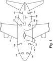
- FIG. 1 is a schematic block diagram illustrating WAIC network controller 10, WAIC routers 12A and 12B, WAIC transceivers 14A, 14B, 14C, 14D, 14E, 14F, 14G, 14H, and radio altimeters 16A and 16B disposed on aircraft 18.
- WAIC communications can be coordinated to avoid radio altimeter signals emitted by radio altimeters 16A and 16B, thereby reducing interference and increasing WAIC communications reliability.
- Coordination of WAIC communications can be accomplished by adjusting the size of packets of WAIC communications and/or adjusting transmission timing of WAIC communications packets, so that WAIC communications take place in frequency bands during times that are not occupied by radio altimeter signals from radio altimeters 16A and 16B.
- a pattern of time stamp intervals can be identified as a repetition of time stamp intervals ⁇ t 4 - ⁇ t 6 and time stamp intervals ⁇ t 10 - ⁇ t 12 .
- the pattern of time stamp intervals corresponds to a pattern of radio altimeter signals on frequency band 28.
- the WAIC network controller can identify a pattern of radio altimeter signals on frequency band 28 and identify a pattern of time stamp intervals corresponding to time between the radio altimeter signals.
- time stamp T 1i corresponds to the time that the radio altimeter signal enters frequency band 28
- time stamp T 1o corresponds to the time that the radio altimeters signal exits frequency band 28.
- time stamp T 1i and time stamp T 1o are a more detailed representation of time stamp T 1 of the example of FIG. 2 .
- Time stamp intervals ⁇ t 2 - ⁇ t 4 in the example of FIG. 3 can likewise be determined.
- Each time stamp in the sequence of time stamps T 1 -T 5 comprises two time stamps.
- each time stamp interval in the sequence of time intervals ⁇ t 1 - ⁇ t 4 represents the difference between a time stamp corresponding to a time that a radio altimeter signal exits the frequency band, and the following time stamp corresponding to a time that a radio altimeter signal enters the frequency band. It should be understood that determining the sequence of time stamp intervals in this way is not limited to the example of FIG. 3 . As was described more generally in the example of FIG. 2 and as is further described below, determining a sequence of time stamp intervals for a frequency band can continue in this way until a pattern of time stamp intervals is identified.
- WAIC network controller 10 can, for example, analyze the sequence of time stamp intervals for a pattern using, e.g., a search algorithm (e.g., a depth-first search algorithm, a breadth-first search algorithm, or other search algorithm), a clustering algorithm (e.g., a K-means clustering algorithm or other clustering algorithm), or other pattern recognition techniques.
- a search algorithm e.g., a depth-first search algorithm, a breadth-first search algorithm, or other search algorithm
- a clustering algorithm e.g., a K-means clustering algorithm or other clustering algorithm
- the one or more WAIC transceivers continue to monitor the frequency band (Step 40).
- a plurality of patterns of time stamp intervals corresponding to a plurality of frequency bands is calculated by extrapolating from one or more patterns of time stamp intervals identified at Step 48.
- This calculation can be done, for example, by using, among other factors, the minimum and maximum frequency of the radio altimeters signals that are being monitored, and by assuming that the number of radio altimeters is constant and the slope of the radio altimeter sweeps is constant. By doing this calculation, the frequencies of the radio altimeter signals over time, i.e., the radio altimeter sweeps, are known, and a plurality of patterns of time stamp intervals corresponding to a plurality of frequency bands can be identified.
- coordinating the WAIC communications to avoid interference with the radio altimeter signals can include reordering packets based, at least in part, on packet size.
- WAIC network controller 10 can reorder packets depending on the size of the packets that are being reordered, so that packets are sent and received during time stamp intervals and thereby avoid interference with radio altimeter signals.
- the transmission timing of a relatively small data packet and a relatively large data packet can be reordered so that transmission of the relatively small data packet can take place during a relatively small time stamp interval and the transmission of the relatively large data packet can take place during a relatively large time stamp interval.
- coordinating the WAIC communications to avoid interference with the radio altimeter signals can include selecting a frequency band for WAIC communications.
- WAIC network controller 10 can select a pattern of time stamp intervals favorable to reliable WAIC communications and select the frequency band corresponding to that pattern of time stamp intervals. More specifically, WAIC network controller 10 can select a pattern of time stamp intervals, and the corresponding frequency band, in which there are, e.g., relatively large time stamp intervals, time stamp intervals with a relatively consistent size, or time stamp intervals that are in any other way favorable to coordinating WAIC communications with the radio altimeter signals.
- the one or more patterns of time stamp intervals are communicated to one or more WAIC routers (Step 54).
- the one or more WAIC routers (e.g., WAIC routers 12A and 12B of FIG. 1 ), can be wired to, e.g., WAIC network controller 10, and the one or more WAIC routers can communicate wirelessly with the one or more WAIC transceivers (e.g., WAIC transceivers 14A-14H).
- the one or more WAIC routers can be used for communication between the WAIC network controller and the one or more WAIC transceivers. Accordingly, by communicating the one or more patterns of time stamp intervals to the one or more routers, the WAIC network controller can coordinate WAIC communications, which include the one or more WAIC transceivers, with the one or more patterns of time stamp intervals.
- a method for coordinating Wireless Avionics Intra-Communications (WAIC) communications with a radio altimeter signal includes monitoring a frequency band and recording a sequence of time stamps, each time stamp of the sequence of time stamps corresponding to a time at which a strength of the radio altimeter signal exceeds a threshold signal strength in the frequency band.
- the method further includes calculating time stamp intervals between successive time stamps to produce a sequence of time stamp intervals, and identifying a pattern of time stamp intervals in the sequence of time stamp intervals.
- the method further includes coordinating the WAIC communications with the pattern of time stamp intervals to avoid interference with the radio altimeter signal.
- Coordinating the WAIC communications with the pattern of time stamp intervals to avoid the interference with the altimeter signal can further include selecting the frequency band for the WAIC communications.
- a system for coordinating WAIC communications with a radio altimeter signal includes a WAIC transceiver and a WAIC network controller.
- the WAIC network controller is configured to: monitor a frequency band; record a sequence of time stamps, each time stamp of the sequence of time stamps corresponding to a time at which a strength of the radio altimeter signal exceeds a threshold signal strength in the frequency band; calculate time stamp intervals between successive time stamps to produce a sequence of time stamp intervals; identify a pattern of time stamp intervals in the sequence of time stamp intervals; and coordinate the WAIC communications with the pattern of time stamp intervals to avoid interference with the radio altimeter signal.
- the WAIC network controller can be configured to monitor the integrity of the WAIC communications, and adjust the WAIC communications in response to determining that the integrity of the WAIC communications does not satisfy threshold integrity criteria.
- the frequency band can be an adjustable range between 4200 MHz and 4400 MHz.
- the WAIC network controller can be configured to identify a pattern of time stamp intervals in the plurality of time stamp intervals by using three or more successive time stamp intervals.
- the WAIC network controller can be configured to calculate, by extrapolating from a pattern of time stamp intervals, a plurality of patterns of time stamp intervals corresponding to a plurality of frequency bands.
Landscapes
- Engineering & Computer Science (AREA)
- Computer Networks & Wireless Communication (AREA)
- Signal Processing (AREA)
- Quality & Reliability (AREA)
- Physics & Mathematics (AREA)
- Astronomy & Astrophysics (AREA)
- Aviation & Aerospace Engineering (AREA)
- General Physics & Mathematics (AREA)
- Mobile Radio Communication Systems (AREA)
- Radar Systems Or Details Thereof (AREA)
- Monitoring And Testing Of Transmission In General (AREA)
Abstract
Description
- The present disclosure relates in general to wireless communications, and in particular to Wireless Avionics Intra-Communications (WAIC) reliability.
- Modern aircraft typically transmit data between sensors and systems positioned about the aircraft using wired aircraft data buses, such as serial or other wired data buses. Using the data buses, data is routed between producing systems and consuming systems for operational control of the aircraft, such as for prognostics and health management, determination of air quality, detection of pathogens, or other operations of the aircraft.
- Recently, to decrease the space, weight, and cost associated with wired aircraft data buses, wireless communication between aircraft systems and/or sensors has been considered. Radio Frequency spectrum in the
frequency range 4200 MHz and 4400 MHz is specifically reserved for aircraft use. This spectrum is now allowed for Wireless Avionics Intra-Communications (WAIC) by the International Telecommunications Union (ITU) resolution 423 at the World Radio Council 2015. Primary allocation of the 4200 MHz - 4400 MHz spectrum is for the Radio Altimeter (RA), a flight safety critical device that determines the altitude of the aircraft above ground. - Because of high power radio altimeter signals, WAIC communications can be affected by interference with radio altimeters. Accordingly, WAIC packets can be corrupted, resulting in errors in WAIC communications.
- This issue is complicated by several factors. First, there are multiple radio altimeters on an aircraft. Second, an aircraft on the ground can be in the radio frequency range of radio altimeters of other aircraft. Third, radio altimeters transmit radio signals across the entire frequency range from 4200 MHz to 4400 MHz, making it impractical to simply divide the frequency spectrum so that radio altimeters use a sub-spectrum and WAIC communications use a different sub-spectrum. Fourth, many different types of aircraft have been using radio altimeters for years, meaning that it is impractical to modify the radio altimeters of legacy aircraft to co-exist with WAIC transmissions.
- In one example, a method for coordinating Wireless Avionics Intra-Communications (WAIC) communications with a radio altimeter signal includes monitoring a frequency band and recording a sequence of time stamps, each time stamp of the sequence of time stamps corresponding to a time at which a strength of the radio altimeter signal exceeds a threshold signal strength in the frequency band. The method further includes calculating time stamp intervals between successive time stamps to produce a sequence of time stamp intervals, and identifying a pattern of time stamp intervals in the sequence of time stamp intervals. The method further includes coordinating the WAIC communications with the pattern of time stamp intervals to avoid interference with the radio altimeter signal.
- In another example, a system for coordinating WAIC communications with a radio altimeter signal includes a WAIC transceiver and a WAIC network controller. The WAIC network controller is configured to monitor a frequency band and record a sequence of time stamps, each time stamp of the sequence of time stamps corresponding to a time at which a strength of the radio altimeter signal exceeds a threshold signal strength in the frequency band. The WAIC network controller is further configured to calculate time stamp intervals between successive time stamps to produce a sequence of time stamp intervals, identify a pattern of time stamp intervals in the sequence of time stamp intervals, and coordinate the WAIC communications with the pattern of time stamp intervals to avoid interference with the radio altimeter signal.
-
-
FIG. 1 is a schematic block diagram of an example aircraft that includes WAIC transceivers, WAIC routers, a WAIC network controller, and altimeters. -
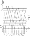
FIG. 2 is a graph illustrating example altimeter sweeps over a range of frequencies and time stamp intervals between time stamps representing interference from radio altimeter signals on a frequency channel. -
FIG. 3 is a graph illustrating a portion of the graph ofFIG. 2 in further detail. -
FIG. 4 is a flow diagram illustrating example operations for identifying a plurality of patterns of time stamp intervals. -
FIG. 1 is a schematic block diagram illustratingWAIC network controller 10,WAIC routers WAIC transceivers radio altimeters aircraft 18. - In the example of
FIG. 1 , WAICnetwork controller 10, which can be a general network controller configured for WAIC communications, is wired for communications withWAIC routers FIG. 1 ,WAIC routers WAIC transceivers 14A-14H. WAICtransceivers 14A-14H can communicate with WAICnetwork controller 10 via WAICrouters WAIC routers WAIC transceivers 14A-14H, it should be understood that any number of one or more WAIC transceivers can be used and located at various positions throughoutaircraft 18, such as a single WAIC transceiver or any two or more WAIC transceivers. In the example ofFIG. 1 ,radio altimeters aircraft 18 to transmit radio signals toward the ground during flight and to determine an altitude ofaircraft 18 based on returns of the transmitted signals. Although illustrated as tworadio altimeters aircraft 18, it should be understood that any number of one or more radio altimeters can be used and located at various positions. - As is further described below,
WAIC network controller 10 can useWAIC transceivers 14A-14H to identify patterns of time stamp intervals between time stamps corresponding to radio altimeter signals fromradio altimeters network controller 10 can also be used, as described below, to coordinate WAIC communications with radio altimeter signals fromradio altimeters network controller 10 can useWAIC routers WAIC transceivers 14A-14H. WAICtransceivers 14A-14H can be used, among other things, to monitor one or more frequency bands for radio altimeter signals, as described below. -
Radio altimeters aircraft 18. To find the altitude above ground level ofaircraft 18,radio altimeters radio altimeters radio altimeters WAIC transceivers 14A-14H as, e.g., interference. However, such detections can be utilized in combination withWAIC network controller 10 to identify timing of the interference for use in coordinating the WAIC communications to avoid the interference. - For instance, as is further described below, WAIC communications can be coordinated to avoid radio altimeter signals emitted by
radio altimeters radio altimeters network controller 10 can useWAIC transceivers 14A-14H to monitor one or more frequency bands for radio altimeter signals, register a time stamp in response to sensing a radio altimeter signal strength greater than a threshold, and calculate a time stamp interval between time stamps. The time stamp interval corresponds to a time during which a frequency band is not occupied by a radio altimeter signal. - Accordingly, WAIC
network controller 10 can coordinate WAIC communications to avoid radio altimeter signals fromradio altimeters network controller 10, implementing techniques of this disclosure, can therefore help to improve WAIC communications reliability. -
FIG. 2 is a graph illustratingfrequency axis 20 andtime axis 22.FIG. 2 also illustratesminimum frequency 24,maximum frequency 26,frequency band 28, first altimeter sweep 30,second altimeter sweep 32, third altimeter sweep 34, time stamps T1-T13, and time stamp intervals Δt1-Δt12. First altimeter sweep 30, second altimeter sweep 32, andthird altimeter sweep 34 are respectively represented by a line, a line with long dashes, and a line with a pattern of long dashes and dots. - In the example of
FIG. 2 , onfrequency axis 20, frequency increases from left to right;time axis 22 illustrates passage of time from top to bottom. In the example ofFIG. 2 ,minimum frequency 24 is 4200 megahertz (MHz), andmaximum frequency 26 is 4400 MHz. In other examples,minimum frequency 24 can be a frequency that is different than 4200 MHz, andmaximum frequency 26 can be a frequency that is different than 4400 MHz -
Frequency band 28 is an adjustable frequency range (e.g., adaptive) and can be a subset of the frequency range betweenminimum frequency 24 andmaximum frequency 26. For purposes of clarity and ease of discussion,frequency band 28 is illustrated as a dotted line in the example ofFIG. 2 . As is further described below in the example ofFIG. 3 ,frequency band 28 can be a bounded frequency range onfrequency axis 20.Frequency band 28 can have, for example, a range of 10 MHz, 20 MHz, or another range. Moreover,frequency band 28 is only an example of what can be a plurality of frequency bands, each of which can be an adjustable frequency range that is a subset of the frequency range betweenminimum frequency 24 andmaximum frequency 26. Accordingly, the entire frequency range betweenminimum frequency 24 andmaximum frequency 26 can be divided into a plurality of frequency bands, each of which can have a range of, e.g., 10 MHz, 20 MHz, or another range. - A radio altimeter, (e.g.,
radio altimeters FIG. 1 ), emits a radio signal. In the present disclosure, the one or more radio signals from the one or more radio altimeters change frequency over time betweenminimum frequency 24 andmaximum frequency 26. In the example ofFIG. 2 , there are three radio altimeters, each of which emits a corresponding radio signal. The change in frequency over time of the three radio altimeter signals is represented, respectively, byfirst altimeter sweep 30,second altimeter sweep 32, andthird altimeter sweep 34. AlthoughFIG 2 . illustrates three altimeter sweeps, it should be understood that there can be more or fewer than three altimeter sweeps corresponding to more or fewer than three radio altimeters. - In the example of
FIG. 2 , one or more WAIC transceivers, (e.g.,WAIC transceivers 14A-14H ofFIG. 1 ), have been configured by a WAIC network controller, (e.g.,WAIC network controller 10 ofFIG. 1 ), to monitorfrequency band 28. The one or more WAIC transceivers monitorfrequency band 28 for a radio altimeter signal with a signal strength that is greater than an adjustable threshold strength, such as a threshold signal strength of -30 decibel-milliwatts (dBm). As is further described below, a time stamp is recorded in response to the one or more WAIC transceivers sensing a radio altimeter signal with a strength greater than a threshold strength. In the example ofFIG 2 ., time stamp T1 is recorded in response to sensing a radio altimeter signal corresponding tofirst altimeter sweep 30 that is greater than the threshold onfrequency band 28. As is further described below in the example ofFIG. 3 , time stamp T1 can also be described as comprising two time stamps: time stamp T1i and time stamp T1o, which correspond, respectively, to the time at which the radio altimeter signal enters and exitsfrequency band 28. - Furthermore, in the example of
FIG 2 ., a sequence of time stamps T1-T13 is recorded. Each of time stamps T1-T13 is recorded in response to sensing the radio altimeter signal strength greater than the threshold onfrequency band 28. As illustrated inFIG. 2 , each of the time stamps in the sequence of time stamps T1-T13 can represent a time at which a radio signal corresponding to any one offirst altimeter sweep 30,second altimeter sweep 32, orthird altimeter sweep 34 is sensed onfrequency band 28. So, regardless of the source of the radio altimeter signal, each time stamp of the sequence of time stamps T1-T13 corresponds to a time at which a radio altimeter signal is actively transmitting onfrequency band 28. - As further described below, a WAIC network controller, (e.g.,
WAIC network controller 10 ofFIG. 1 ) can calculate a time stamp interval between successive time stamps. The WAIC network controller can further be configured to calculate a plurality of time stamp intervals between successive time stamps in a sequence of time stamps, resulting in a sequence of time stamp intervals. In the example ofFIG. 2 , time stamp interval Δt1 is calculated as the difference between time stamp T1 and time stamp T2. Time stamp interval Δt1 therefore represents the amount of time between time stamp T1 and time stamp T2. - Furthermore, in the example of
FIG. 2 , time stamp intervals Δt1-Δt12 correspond to the differences between successive time stamps in time stamp sequence T1-T13. As such, time stamp intervals Δt1-Δt12 correspond to periods of time during which there is no radio altimeter signal with a strength above a threshold onfrequency band 28. In other words, time stamp intervals Δt1-Δt12 represent times that WAIC communications can take place onfrequency band 28 without radio altimeter signals with a strength above a threshold also usingfrequency band 28. Time stamps T1-T13 and time stamp intervals Δt1-Δt12 can, in this way, be used to avoid interference from radio altimeter signals onfrequency band 28. - A WAIC network controller can also be configured, as further described below, to identify a pattern of time stamp intervals in a sequence of time stamp intervals. In the example of
FIG. 2 , a pattern of time stamp intervals in time stamp interval sequence Δt1-Δt12 can be identified. For instance, the WAIC network controller can identify the pattern of time stamp intervals as repeating sequences of intervals using, e.g., a depth-first or breadth-first search algorithm, a K-means clustering algorithm or another clustering algorithm, or other pattern recognition techniques. For instance, the WAIC network controller can identify a pattern of any two or more repeating time stamp intervals, such as two repeating time stamp intervals, three repeating time stamp intervals, or other numbers of repeating time stamp intervals. - In the example of
FIG. 2 , a pattern of time stamp intervals can be identified as a repetition of time stamp intervals Δt4-Δt6 and time stamp intervals Δt10-Δt12. As illustrated inFIG. 2 , the pattern of time stamp intervals corresponds to a pattern of radio altimeter signals onfrequency band 28. Accordingly, the WAIC network controller can identify a pattern of radio altimeter signals onfrequency band 28 and identify a pattern of time stamp intervals corresponding to time between the radio altimeter signals. Furthermore, because radio altimeters are typically configured to vary (or sweep) frequencies at which they transmit the radio altimeter signal across the allocated frequency spectrum (e.g., 4200 MHz - 4400 MHz) at a constant rate, the WAIC network controller can plan WAIC communications (e.g., coordinate WAIC communications) onfrequency band 28 by anticipating the repetition of the time stamp intervals. For instance, the WAIC network controller can anticipate the pattern as occurring indefinitely or for a fixed amount of time, thereby avoiding interference with the radio altimeter signals onfrequency band 28. -
FIG. 3 is a graph illustrating a portion of the graph ofFIG 2 in further detail. The example ofFIG. 3 provides a more detailed description offrequency band 28, time stamps T1-T5, and time stamp intervals Δt1-Δt4 ofFIG 2 . For purposes of clarity and ease of discussion, the numbering of elements in the example ofFIG. 3 is similar to the numbering of elements in the example ofFIG. 2 . Consequently,FIG. 3 illustratesfrequency axis 20,time axis 22,minimum frequency 24,frequency band 28,first altimeter sweep 30,second altimeter sweep 32,third altimeter sweep 34, and time stamp intervals Δt1-Δt4. - Unlike the illustration of
frequency band 28 inFIG. 2 ,frequency band 28 inFIG. 3 is illustrated as a frequency range onfrequency axis 20. As such, it is illustrated as bounded by two dotted lines, which represent the minimum and maximum offrequency band 28.Frequency band 28 can have a range of, e.g., 10 MHz, 20 MHz, or any other range. - Another difference between the example of
FIG. 2 and the example ofFIG. 3 is the way that time stamps T1-T5 are represented. Take, for example, time stamp T1. Like time stamp T1, time stamp T1i and time stamp T1o correspond to a radio altimeter signal, with a strength greater than a threshold signal strength, corresponding toradio altimeter sweep 30. However, whereas time stamp T1 inFIG. 2 generally corresponds to the time that the radio altimeter signal is sensed onfrequency band 28, time stamp T1i and time stamp T1o correspond, respectively, to the time that the radio altimeter signal has a frequency equal to the minimum and maximum offrequency band 28. In other words, time stamp T1i corresponds to the time that the radio altimeter signal entersfrequency band 28, and time stamp T1o corresponds to the time that the radio altimeters signalexits frequency band 28. In this way, time stamp T1i and time stamp T1o are a more detailed representation of time stamp T1 of the example ofFIG. 2 . - Likewise, each of time stamps T2-T5 in the example of
FIG. 2 are represented in more detail in the example ofFIG. 3 . Each of time stamps T2-T5 are represented as two time stamps: one that corresponds to a time that a radio altimeter sweep and a corresponding signal with a strength greater than a threshold entersfrequency band 28; and another that corresponds to the time that the same radio altimeter sweep and corresponding signal exitsfrequency band 28. - Time stamp intervals Δt1-Δt4 in the example of
FIG. 3 correspond to differences between successive time stamps in time stamp sequence T1-T5, where each time stamp in time stamp sequence T1-T5 is represented in more detail as comprising two time stamps. For example, time stamp interval Δt1 in the example ofFIG. 3 represents the difference between T1o and T2i. In other words, time stamp interval Δt1 corresponds to the time after which the radio altimeter signal corresponding to time stamp T1 has exitedfrequency band 28, and before which the radio altimeter signal corresponding to time stamp T2 has enteredfrequency band 28. As such, time stamp interval Δt1 corresponds to a time that there is no radio altimeter signal with a strength above a threshold onfrequency band 28. - Time stamp intervals Δt2-Δt4 in the example of
FIG. 3 can likewise be determined. Each time stamp in the sequence of time stamps T1-T5 comprises two time stamps. As such, each time stamp interval in the sequence of time intervals Δt1-Δt4 represents the difference between a time stamp corresponding to a time that a radio altimeter signal exits the frequency band, and the following time stamp corresponding to a time that a radio altimeter signal enters the frequency band. It should be understood that determining the sequence of time stamp intervals in this way is not limited to the example ofFIG. 3 . As was described more generally in the example ofFIG. 2 and as is further described below, determining a sequence of time stamp intervals for a frequency band can continue in this way until a pattern of time stamp intervals is identified. -
FIG. 4 is a flow chart illustrating example operations for identifying a pattern of time stamp intervals. For purposes of clarity and ease of discussion, the example operations are described below within the context of the examples ofFIGS. 1 and2 ; however, it should be understood that the context ofFIG. 2 also includes the more detailed description provided in the example ofFIG. 3 - As illustrated in
FIG. 4 , one or more WAIC transceivers are tuned by a WAIC network controller to monitor a frequency band between a minimum frequency and a maximum frequency (Step 40). For example,WAIC network controller 10 can tune one or more ofWAIC transceivers 14A-14H to monitorfrequency band 28, which is a sub-set of the WAIC frequencies (4200 MHz - 4400 MHz). - It is determined whether a radio altimeter signal with a strength greater than a threshold is sensed on the frequency band that is being monitored (Step 42). For instance,
WAIC network controller 10 can set a threshold signal strength of radio altimeter signals, and can determine whether a radio altimeter signal sensed by one or more WAIC transceivers is greater than the threshold signal strength. Depending on, among other considerations, the locations and specifications of the one or more WAIC transceivers, the locations and number of altimeters, the strength of altimeter signals, and the location of the aircraft, the threshold signal strength can vary. In response to determining that a radio altimeter signal with a strength greater than the threshold signal strength has not been sensed on the frequency band ("NO" branch of Step 42), the one or more WAIC transceivers continue to monitor the frequency band (Step 40). - In response to determining that a radio altimeter signal with a strength greater than the threshold signal strength has been sensed on the frequency band ("YES" branch of Step 42), a time stamp is recorded (Step 44). The time stamp corresponds to a time at which the radio altimeter signal with the strength greater than the threshold is sensed on the frequency band being monitored. As described in the example of
FIG. 3 , two time stamps can be recorded, one corresponding to the time at which the radio altimeter signal enters the frequency band and one corresponding to the time at which the radio altimeter signal exits the frequency band. The time stamps can, for example, be recorded byWAIC network controller 10, and can be stored in any way that is accessible to WAIC network controller 10 (e.g., in computer-readable memory of WAIC network controller 10). A plurality of recorded time stamps (e.g., time stamps T1-T13 ofFIG. 2 ) defines a sequence of time stamps. - A time stamp interval is calculated between successive time stamps (Step 46). For example,
WAIC network controller 10 can subtract from a time value of a given time stamp the time value of a sequentially-previous time stamp to determine the time stamp interval between the successive time stamps. In an instance where more than one time stamp interval for a frequency band has been calculated, (i.e., an instance in which three or more time stamps have been recorded for a frequency band) there can be a sequence of time stamp intervals, (e.g., time stamp intervals Δt1-Δt12 ofFIG. 2 .). - It is determined whether there is a pattern of time stamp intervals in the sequence of time stamp intervals (Step 48).
WAIC network controller 10 can, for example, analyze the sequence of time stamp intervals for a pattern using, e.g., a search algorithm (e.g., a depth-first search algorithm, a breadth-first search algorithm, or other search algorithm), a clustering algorithm (e.g., a K-means clustering algorithm or other clustering algorithm), or other pattern recognition techniques. In examples where no pattern of time stamp intervals is identified in the sequence of time stamp intervals ("NO" branch of Step 48), the one or more WAIC transceivers continue to monitor the frequency band (Step 40). In response to identifying a pattern of time stamp intervals in the sequence of time stamp intervals ("YES" branch of Step 48), the pattern of time stamp intervals can be stored (e.g., in computer-readable memory of WAIC network controller 10), and it is determined whether an additional frequency band is to be monitored (Step 50). - By monitoring an additional frequency band ("YES" branch of Step 50), Steps 40-48 are repeated using the new frequency band, starting at
Step 40. By monitoring a plurality of additional frequency bands, i.e., taking the "YES" branch ofStep 50 multiple times and iterating through Steps 40-48 multiple times, a plurality of patterns of time stamp intervals corresponding to a plurality of frequency bands can be identified. In some examples, (e.g.,FIG. 2 ), the frequency range betweenminimum frequency 24 andmaximum frequency 26 can be analyzed by repeating Steps 40-48 for a plurality of frequency bands. Each frequency band can be a subset of the frequency range fromminimum frequency 24 tomaximum frequency 26. Accordingly, repeating Steps 40-48 can result in a plurality of patterns of time stamp intervals corresponding to a plurality of frequency bands, which, together, can represent the entire frequency range fromminimum frequency 24 tomaximum frequency 26. - In other examples, a plurality of patterns of time stamp intervals corresponding to a plurality of frequency bands is calculated by extrapolating from one or more patterns of time stamp intervals identified at
Step 48. This calculation can be done, for example, by using, among other factors, the minimum and maximum frequency of the radio altimeters signals that are being monitored, and by assuming that the number of radio altimeters is constant and the slope of the radio altimeter sweeps is constant. By doing this calculation, the frequencies of the radio altimeter signals over time, i.e., the radio altimeter sweeps, are known, and a plurality of patterns of time stamp intervals corresponding to a plurality of frequency bands can be identified. - In response to determining no additional frequency band is to be monitored ("NO" branch of Step 50), WAIC communications are coordinated with the one or more patterns of time stamp intervals in order to avoid interference with radio altimeter signals (Step 52). In one example,
WAIC network controller 10 coordinates the WAIC communications to avoid the interference with the radio altimeter signals. - As an example, coordinating WAIC communications to avoid interference with the radio altimeter signals can include adjusting the size of one or more WAIC communication data packets. For instance,
WAIC network controller 10 can adjust the size of the one or more WAIC communication packets such that transmission of the packets reliably occurs within time stamp intervals without occurring at times identified as corresponding to the pattern of radio altimeter signals. - As another example, coordinating the WAIC communications to avoid interference with the radio altimeter signals can include adjusting packet transmission timing of WAIC communications. For instance,
WAIC network controller 10 can adjust transmission timing of one or more WAIC communications packets such that the packets are sent and received within time stamp intervals without occurring at times identified as corresponding to the pattern of radio altimeter signals. - As another example, coordinating the WAIC communications to avoid interference with the radio altimeter signals can include reordering packets based, at least in part, on packet size. For instance,
WAIC network controller 10 can reorder packets depending on the size of the packets that are being reordered, so that packets are sent and received during time stamp intervals and thereby avoid interference with radio altimeter signals. For example, the transmission timing of a relatively small data packet and a relatively large data packet can be reordered so that transmission of the relatively small data packet can take place during a relatively small time stamp interval and the transmission of the relatively large data packet can take place during a relatively large time stamp interval. - As another example, coordinating the WAIC communications to avoid interference with the radio altimeter signals can include selecting a frequency band for WAIC communications. For instance,
WAIC network controller 10 can select a pattern of time stamp intervals favorable to reliable WAIC communications and select the frequency band corresponding to that pattern of time stamp intervals. More specifically,WAIC network controller 10 can select a pattern of time stamp intervals, and the corresponding frequency band, in which there are, e.g., relatively large time stamp intervals, time stamp intervals with a relatively consistent size, or time stamp intervals that are in any other way favorable to coordinating WAIC communications with the radio altimeter signals. - As another example, coordinating the WAIC communications to avoid interference with radio altimeter signals can include changing the selected frequency band (i.e., the selected subset of frequencies) for WAIC communications. For instance,
WAIC network controller 10 can change the frequency band for WAIC communications depending, at least in part, on the patterns of time stamp intervals corresponding to the frequency bands. In the case where WAIC communications is taking place on a frequency band with a corresponding pattern of time stamp intervals that are unfavorable to coordinating WAIC communications with radio altimeter signals, (e.g., time stamp intervals that are short and/or inconsistent),WAIC network controller 10 can change the frequency band for WAIC communications.WAIC network controller 10 can change WAIC communications to a frequency band with a corresponding pattern of time stamp intervals that is more favorable to reliable and efficient WAIC communications, e.g., a pattern with large, consistent, or in any other way favorable time stamp intervals. In this way,WAIC network controller 10 can, for example, change WAIC communications from one frequency band to another so that WAIC communications can, irrespective of the frequency band, take place during time stamp intervals without occurring at times corresponding to the pattern of radio altimeter signals. - In some examples,
WAIC network controller 10 can monitor integrity of the WAIC communications and adjust the WAIC communications in response to identifying an error rate above a threshold error rate. Errors in WAIC communications can be detected e.g., by using an error detection method, such as by using a parity bit, a checksum, or a multi-bit cyclic redundancy check (CRC). A threshold for the error rate in WAIC communications can be, for example, a number of errors per unit time, a number of errors per number of packets, or any other measure of digital communications integrity. An increase in error rate can be caused by, among other reasons, the aircraft being in range of radio altimeters from other aircraft (e.g., when the aircraft is on or near the ground). In some examples, a detected increase in error rate (i.e., decrease in integrity) can be caused by a desynchronization of the WAIC communications with the one or more determined patterns of time stamp intervals. - In response to determining that WAIC communications error rate is above a threshold error rate, WAIC communications can be adjusted. WAIC communications can be adjusted by performing one or more of Steps 40 - 50. For example, a frequency band can be monitored for radio altimeter signals to update a pattern of time stamp intervals that correspond to times during which there is no interference from radio altimeter signals. This pattern of time stamp intervals can be compared, for example, with the previous pattern of time stamp intervals for that frequency band. The amount that WAIC communications are desynchronized with the pattern of time stamp intervals can then be identified, and WAIC communications can be adjusted accordingly. In another example, updating a pattern of time stamp intervals, by performing one or more of Steps 40-48, can be repeated for a plurality of frequency bands, resulting in a plurality of updated patterns of time stamp intervals. WAIC communications can therefore be coordinated with the updated plurality of patterns of time stamp intervals.
- The one or more patterns of time stamp intervals are communicated to one or more WAIC routers (Step 54). The one or more WAIC routers, (e.g.,
WAIC routers FIG. 1 ), can be wired to, e.g.,WAIC network controller 10, and the one or more WAIC routers can communicate wirelessly with the one or more WAIC transceivers (e.g.,WAIC transceivers 14A-14H). The one or more WAIC routers can be used for communication between the WAIC network controller and the one or more WAIC transceivers. Accordingly, by communicating the one or more patterns of time stamp intervals to the one or more routers, the WAIC network controller can coordinate WAIC communications, which include the one or more WAIC transceivers, with the one or more patterns of time stamp intervals. - Accordingly, techniques of this disclosure enable coordinating WAIC communications with patterns of time stamp intervals that correspond to times on frequency bands during which there is no interference from radio altimeter signals with a strength above a threshold strength. By coordinating WAIC communications to avoid interference with radio altimeter signals, WAIC communications reliability is improved and WAIC communications devices can be better integrated with aircrafts that use radio altimeters.
- The following are non-exclusive descriptions of possible embodiments of the present invention.
- A method for coordinating Wireless Avionics Intra-Communications (WAIC) communications with a radio altimeter signal includes monitoring a frequency band and recording a sequence of time stamps, each time stamp of the sequence of time stamps corresponding to a time at which a strength of the radio altimeter signal exceeds a threshold signal strength in the frequency band. The method further includes calculating time stamp intervals between successive time stamps to produce a sequence of time stamp intervals, and identifying a pattern of time stamp intervals in the sequence of time stamp intervals. The method further includes coordinating the WAIC communications with the pattern of time stamp intervals to avoid interference with the radio altimeter signal.
- The method of the preceding paragraph can optionally include, additionally and/or alternatively, any one or more of the following features, configurations, operations, and/or additional components:
- Coordinating the WAIC communications with the pattern of time stamp intervals can include communicating the pattern of time stamp intervals to a WAIC router.
- The method can further include monitoring integrity of the WAIC communications, and adjusting the WAIC communications in response to determining that the integrity of the WAIC communications does not satisfy threshold integrity criteria.
- Adjusting the WAIC communications in response to determining that the integrity of the WAIC communications does not satisfy threshold integrity criteria can include: monitoring the frequency band; recording an updated sequence of time stamps, each time stamp of the updated sequence of time stamps corresponding to a time at which the strength of the radio altimeter signal exceeds the threshold signal strength in the frequency band; calculating an updated plurality of time stamp intervals between successive time stamps in the updated sequence of time stamps; communicating the updated pattern of time stamp intervals to the WAIC router; and coordinating the WAIC communications with the updated pattern of time stamp intervals.
- The frequency band can be an adaptive in the range between 4200 MHz to 4400 MHz.
- Identifying the pattern of time stamp intervals in the plurality of time stamp intervals can include using three or more consecutive time stamp intervals.
- The method can further include identifying a plurality of patterns of time stamp intervals corresponding to a plurality of frequency bands.
- The method can further include calculating, by extrapolating from the pattern of time stamp intervals, a plurality of patterns of time stamp intervals corresponding to a plurality of frequency bands.
- Coordinating the WAIC communications with the pattern of time stamp intervals to avoid the interference with the altimeter signal can include one or more of: adjusting a packet size of the WAIC communications; and adjusting packet transmission timing of the WAIC communications.
- Coordinating the WAIC communications with the pattern of time stamp intervals to avoid the interference with the altimeter signal can further include selecting the frequency band for the WAIC communications.
- A system for coordinating WAIC communications with a radio altimeter signal includes a WAIC transceiver and a WAIC network controller. The WAIC network controller is configured to: monitor a frequency band; record a sequence of time stamps, each time stamp of the sequence of time stamps corresponding to a time at which a strength of the radio altimeter signal exceeds a threshold signal strength in the frequency band; calculate time stamp intervals between successive time stamps to produce a sequence of time stamp intervals; identify a pattern of time stamp intervals in the sequence of time stamp intervals; and coordinate the WAIC communications with the pattern of time stamp intervals to avoid interference with the radio altimeter signal.
- The system of the preceding paragraph can optionally include, additionally and/or alternatively, any one or more of the following features, configurations, operations, and/or additional components:
- The WAIC network controller can be configured to coordinate the WAIC communications with the pattern of time stamp intervals by communicating the pattern of time stamp intervals to a WAIC router.
- The WAIC network controller can be configured to monitor the integrity of the WAIC communications, and adjust the WAIC communications in response to determining that the integrity of the WAIC communications does not satisfy threshold integrity criteria.
- The WAIC network controller can be configured to adjust the WAIC communications in response to determining that the integrity of the WAIC communications does not satisfy threshold integrity criteria by being configured to: monitor a frequency band; record an updated sequence of time stamps, each time stamp of the updated sequence of time stamps corresponding to a time at which a strength of the radio altimeter signal exceeds a threshold signal strength in the frequency band; calculate updated time stamp intervals between successive time stamps to produce an updated sequence of time stamp intervals; identify an updated pattern of time stamp intervals in the sequence of time stamp intervals; and coordinate the WAIC communications with the updated pattern of time stamp intervals to avoid interference with the radio altimeter signal.
- The frequency band can be an adjustable range between 4200 MHz and 4400 MHz.
- The WAIC network controller can be configured to identify a pattern of time stamp intervals in the plurality of time stamp intervals by using three or more successive time stamp intervals.
- The WAIC network controller can be configured to identify a plurality of patterns of time stamp intervals corresponding to a plurality of frequency bands.
- The WAIC network controller can be configured to calculate, by extrapolating from a pattern of time stamp intervals, a plurality of patterns of time stamp intervals corresponding to a plurality of frequency bands.
- The WAIC network controller can be configured to coordinate the WAIC communications with the pattern of time stamp intervals to avoid the interference with the altimeter signal further by being configured to adjust one or more of: a packet size of the WAIC communications; and packet transmission timing of the WAIC communications.
- The WAIC network controller can be configured to coordinate the WAIC communications with the pattern of time stamp intervals to avoid the interference with the altimeter signal by selecting the frequency band for the WAIC communications.
- While the invention has been described with reference to an exemplary embodiment(s), it will be understood by those skilled in the art that various changes may be made and equivalents may be substituted for elements thereof without departing from the scope of the invention as defined by the claims. In addition, many modifications may be made to adapt a particular situation or material to the teachings of the invention without departing from the scope of the claims. Therefore, it is intended that the invention not be limited to the particular embodiment(s) disclosed, but that the invention will include all embodiments falling within the scope of the appended claims.
Claims (15)
- A method for coordinating Wireless Avionics Intra-Communications (WAIC) communications with a radio altimeter signal, the method comprising:monitoring (40) a frequency band;recording (44) a sequence of time stamps, each time stamp of the sequence of time stamps corresponding to a time at which a strength of the radio altimeter signal exceeds a threshold signal strength in the frequency band;calculating (46) time stamp intervals between successive time stamps to produce a sequence of time stamp intervals;identifying (48) a pattern of time stamp intervals in the sequence of time stamp intervals; andcoordinating (52) the WAIC communications with the pattern of time stamp intervals to avoid interference with the radio altimeter signal.
- The method of claim 1,
wherein coordinating the WAIC communications with the pattern of time stamp intervals comprises communicating (54) the pattern of time stamp intervals to a WAIC router (12A,B). - The method of claim 1 or 2, further comprising:monitoring integrity of the WAIC communications; andadjusting the WAIC communications in response to determining that the integrity of the WAIC communications does not satisfy threshold integrity criteria.
- The method of claim 3,
wherein adjusting the WAIC communications in response to determining that the integrity of the WAIC communications does not satisfy the threshold integrity criteria comprises:monitoring the frequency band;recording an updated sequence of time stamps, each time stamp of the updated sequence of time stamps corresponding to a time at which the strength of the radio altimeter signal exceeds the threshold signal strength in the frequency band;calculating an updated plurality of time stamp intervals between successive time stamps in the updated sequence of time stamps;communicating the updated pattern of time stamp intervals to the WAIC router; andcoordinating the WAIC communications with the updated pattern of time stamp intervals. - The method of any preceding claim,
wherein the frequency band is adaptive between 4200 MHz and 4400 MHz. - The method of any preceding claim,
wherein identifying the pattern of time stamp intervals in the plurality of time stamp intervals further comprises using three or more consecutive time stamp intervals. - The method of any preceding claim, further comprising:
identifying a plurality of patterns of time stamp intervals corresponding to a plurality of frequency bands. - The method of any of claims 1 to 6, further comprising:
calculating, by extrapolating from the pattern of time stamp intervals, a plurality of patterns of time stamp intervals corresponding to a plurality of frequency bands. - The method of any preceding claim,wherein coordinating the WAIC communications with the pattern of time stamp intervals to avoid the interference with the altimeter signal further comprises one or more of: adjusting a packet size of the WAIC communications; and adjusting packet transmission timing of the WAIC communications; and/orwherein coordinating the WAIC communications with the pattern of time stamp intervals to avoid the interference with the altimeter signal further comprises selecting the frequency band for the WAIC communications.
- A system for coordinating Wireless Avionics Intra-Communications (WAIC) communications with a radio altimeter signal, the system comprising:a WAIC transceiver (14A-H); anda WAIC network controller (10) configured to:monitor (40) a frequency band;record (44) a sequence of time stamps, each time stamp of the sequence of time stamps corresponding to a time at which a strength of the radio altimeter signal exceeds a threshold signal strength in the frequency band;calculate (46) time stamp intervals between successive time stamps to produce a sequence of time stamp intervals;identify (48) a pattern of time stamp intervals in the sequence of time stamp intervals; andcoordinate (52) the WAIC communications with the pattern of time stamp intervals to avoid interference with the radio altimeter signal; optionally wherein the frequency band is an adjustable range between 4200 MHz and 4400 MHz.
- The system of claim 10,
wherein the WAIC network controller (10) is configured to coordinate the WAIC communications with the pattern of time stamp intervals by communicating (54) the pattern of time stamp intervals to a WAIC router (12A,B). - The system of claim 10 or 11,wherein the WAIC network controller (10) is further configured to:monitor the integrity of the WAIC communications; andadjust the WAIC communications in response to determining that the integrity of the WAIC communications does not satisfy threshold integrity criteria; and optionallywherein the WAIC network controller (10) is configured to adjust the WAIC communications in response to determining that the integrity of the WAIC communications does not satisfy threshold integrity criteria by being configured to:monitor the frequency band;record an updated sequence of time stamps, each time stamp of the updated sequence of time stamps corresponding to a time at which the strength of the radio altimeter signal exceeds the threshold signal strength in the frequency band;calculate an updated plurality of time stamp intervals between successive time stamps in the updated sequence of time stampscommunicate the updated pattern of time stamp intervals to the WAIC router; andcoordinate the WAIC communications with the updated pattern of time stamp intervals.
- The system of claim 10, 11, or 12,
wherein the WAIC network controller is configured to identify a pattern of time stamp intervals in the plurality of time stamp intervals by using three or more successive time stamp intervals. - The system of any of claims 10 to 13,wherein the WAIC network controller (10) is further configured to identify a plurality of patterns of time stamp intervals corresponding to a plurality of frequency bands; orwherein the WAIC network controller (10) is further configured to calculate, by extrapolating from a pattern of time stamp intervals, a plurality of patterns of time stamp intervals corresponding to a plurality of frequency bands.
- The system of any of claims 10 to 14,wherein the WAIC network controller (10) is configured to coordinate the WAIC communications with the pattern of time stamp intervals to avoid the interference with the altimeter signal further by being configured to adjust one or more of: a packet size of the WAIC communications; and packet transmission timing of the WAIC communications; and/orwherein the WAIC network controller (10) is configured to coordinate the WAIC communications with the pattern of time stamp intervals to avoid the interference with the altimeter signal by selecting the frequency band for the WAIC communications.
Applications Claiming Priority (1)
| Application Number | Priority Date | Filing Date | Title |
|---|---|---|---|
| IN202041035565 | 2020-08-18 |
Publications (2)
| Publication Number | Publication Date |
|---|---|
| EP3962213A1 true EP3962213A1 (en) | 2022-03-02 |
| EP3962213B1 EP3962213B1 (en) | 2024-11-06 |
Family
ID=77543302
Family Applications (1)
| Application Number | Title | Priority Date | Filing Date |
|---|---|---|---|
| EP21191843.8A Active EP3962213B1 (en) | 2020-08-18 | 2021-08-18 | Coordination of wireless avionics intra-communications (waic) with radio altimeter signals |
Country Status (2)
| Country | Link |
|---|---|
| US (1) | US11621767B2 (en) |
| EP (1) | EP3962213B1 (en) |
Families Citing this family (2)
| Publication number | Priority date | Publication date | Assignee | Title |
|---|---|---|---|---|
| US20230222217A1 (en) * | 2022-01-07 | 2023-07-13 | Xilinx, Inc. | Adaptive integrity levels in electronic and programmable logic systems |
| US12468011B2 (en) * | 2022-06-07 | 2025-11-11 | Honeywell International Inc. | Systems and methods for mitigating telecommunications signal interference to radar altimeters |
Citations (2)
| Publication number | Priority date | Publication date | Assignee | Title |
|---|---|---|---|---|
| EP3182781A1 (en) * | 2015-12-17 | 2017-06-21 | Honeywell International Inc. | Cognitive allocation of tdma resources in the presence of a radio altimeter |
| EP3316613A1 (en) * | 2016-10-28 | 2018-05-02 | Wipro Limited | Methods and systems for managing wireless avionics intra-communication systems (waicss) in radio altimeter band |
Family Cites Families (7)
| Publication number | Priority date | Publication date | Assignee | Title |
|---|---|---|---|---|
| US7683827B2 (en) | 2004-12-15 | 2010-03-23 | Valeo Radar Systems, Inc. | System and method for reducing the effect of a radar interference signal |
| US8923225B2 (en) | 2011-04-05 | 2014-12-30 | Her Majesty The Queen In Right Of Canada, As Represented By The Minister Of Industry, Through The Communications Research Centre Canada | Cognitive WiFi radio network |
| US9755796B2 (en) | 2015-03-18 | 2017-09-05 | Honeywell International Inc. | System and method of using radio altimeter frequency spectrum for wireless signals |
| US10725170B2 (en) | 2015-12-17 | 2020-07-28 | Honeywell International Inc. | Frequency modulated continuous wave radio altimeter spectral monitoring |
| US10177868B2 (en) | 2015-12-17 | 2019-01-08 | Honeywell International Inc. | Systems and methods to synchronize wireless devices in the presence of a FMCW radio altimeter |
| US10495728B2 (en) | 2017-03-06 | 2019-12-03 | Honeywell International Inc. | Signal interference prevention system for a frequency-modulated continuous wave radar altimeter |
| US11482116B2 (en) | 2017-07-07 | 2022-10-25 | Panasonic Intellectual Property Management Co., Ltd. | Communication apparatus and communication control method |
-
2021
- 2021-08-16 US US17/403,345 patent/US11621767B2/en active Active
- 2021-08-18 EP EP21191843.8A patent/EP3962213B1/en active Active
Patent Citations (2)
| Publication number | Priority date | Publication date | Assignee | Title |
|---|---|---|---|---|
| EP3182781A1 (en) * | 2015-12-17 | 2017-06-21 | Honeywell International Inc. | Cognitive allocation of tdma resources in the presence of a radio altimeter |
| EP3316613A1 (en) * | 2016-10-28 | 2018-05-02 | Wipro Limited | Methods and systems for managing wireless avionics intra-communication systems (waicss) in radio altimeter band |
Also Published As
| Publication number | Publication date |
|---|---|
| US20220060249A1 (en) | 2022-02-24 |
| US11621767B2 (en) | 2023-04-04 |
| EP3962213B1 (en) | 2024-11-06 |
Similar Documents
| Publication | Publication Date | Title |
|---|---|---|
| EP3962213B1 (en) | Coordination of wireless avionics intra-communications (waic) with radio altimeter signals | |
| US7133686B2 (en) | System and method for identifying interferes in a communication spectrum | |
| US20220400459A1 (en) | Uplink timing adjustment with multiple numerologies | |
| KR101109577B1 (en) | Wireless device, wireless communication system, and method for detecting radio wave | |
| US7149205B2 (en) | Interference detection method and interference avoidance system for wireless communication links | |
| JP4885178B2 (en) | Ultra-wideband wireless network with interference mitigation and related methods | |
| US7733938B2 (en) | Methods and apparatuses for channel assessment | |
| RU2005112248A (en) | DEVICE AND METHOD FOR TRANSMITTING / RECEIVING DATA IN A COMMUNICATION SYSTEM USING A MULTIPLE ACCESS SCHEME | |
| US7529288B2 (en) | Channel qualification for an adaptive frequency hopping method by means of bit or packet error rate measurement and simultaneous field strength measurement | |
| US7903626B2 (en) | Channel qualification and selection in a multichannel radio system by packet error rate measurement | |
| KR20200006540A (en) | Specific jump pattern for telegram splitting | |
| US8238962B2 (en) | System and method for ground station selection | |
| US7440760B2 (en) | Methods and apparatus for allocating bandwidth to communication devices based on signal conditions experienced by the communication devices | |
| US6842625B2 (en) | Method for autonomous frequency management for reliable data communications | |
| US7711027B2 (en) | Wireless communication control method and wireless communication device | |
| EP1560344B1 (en) | Wireless ultra wideband network having frequency BIN transmission level setting and related methods | |
| US20200185966A1 (en) | Electronic apparatus and method | |
| US20210329516A1 (en) | Devices, systems and methods for selecting communication protocol transmission frequencies | |
| CN114258141A (en) | Dynamically switching between shared and time division multiplexed access to a wireless medium based on channel quality | |
| US10812134B2 (en) | Wireless communication apparatus, wireless communication system, wireless communication method, control circuit, and recording medium | |
| JP7703752B2 (en) | Electronic Device, Electronic System, and Method | |
| EP3818667B1 (en) | Low latency wireless protocol for audio and gaming | |
| US20100142464A1 (en) | Method and device for selecting and transmitting variable frame formats | |
| CN114337773B (en) | Narrow-band interference detection and channel selection method for VDES satellite | |
| US20190320341A1 (en) | Method and apparatus for v2x multichannel operation |
Legal Events
| Date | Code | Title | Description |
|---|---|---|---|
| PUAI | Public reference made under article 153(3) epc to a published international application that has entered the european phase |
Free format text: ORIGINAL CODE: 0009012 |
|
| STAA | Information on the status of an ep patent application or granted ep patent |
Free format text: STATUS: THE APPLICATION HAS BEEN PUBLISHED |
|
| AK | Designated contracting states |
Kind code of ref document: A1 Designated state(s): AL AT BE BG CH CY CZ DE DK EE ES FI FR GB GR HR HU IE IS IT LI LT LU LV MC MK MT NL NO PL PT RO RS SE SI SK SM TR |
|
| RAP1 | Party data changed (applicant data changed or rights of an application transferred) |
Owner name: ROSEMOUNT AEROSPACE INC. |
|
| STAA | Information on the status of an ep patent application or granted ep patent |
Free format text: STATUS: REQUEST FOR EXAMINATION WAS MADE |
|
| 17P | Request for examination filed |
Effective date: 20220825 |
|
| RBV | Designated contracting states (corrected) |
Designated state(s): AL AT BE BG CH CY CZ DE DK EE ES FI FR GB GR HR HU IE IS IT LI LT LU LV MC MK MT NL NO PL PT RO RS SE SI SK SM TR |
|
| REG | Reference to a national code |
Ref country code: DE Ref legal event code: R079 Free format text: PREVIOUS MAIN CLASS: H04W0072080000 Ipc: H04W0024080000 Ref country code: DE Ref legal event code: R079 Ref document number: 602021021292 Country of ref document: DE Free format text: PREVIOUS MAIN CLASS: H04W0072080000 Ipc: H04W0024080000 |
|
| RIC1 | Information provided on ipc code assigned before grant |
Ipc: H04W 72/541 20230101ALI20240501BHEP Ipc: H04W 24/08 20090101AFI20240501BHEP |
|
| GRAP | Despatch of communication of intention to grant a patent |
Free format text: ORIGINAL CODE: EPIDOSNIGR1 |
|
| STAA | Information on the status of an ep patent application or granted ep patent |
Free format text: STATUS: GRANT OF PATENT IS INTENDED |
|
| INTG | Intention to grant announced |
Effective date: 20240611 |
|
| GRAS | Grant fee paid |
Free format text: ORIGINAL CODE: EPIDOSNIGR3 |
|
| GRAA | (expected) grant |
Free format text: ORIGINAL CODE: 0009210 |
|
| STAA | Information on the status of an ep patent application or granted ep patent |
Free format text: STATUS: THE PATENT HAS BEEN GRANTED |
|
| AK | Designated contracting states |
Kind code of ref document: B1 Designated state(s): AL AT BE BG CH CY CZ DE DK EE ES FI FR GB GR HR HU IE IS IT LI LT LU LV MC MK MT NL NO PL PT RO RS SE SI SK SM TR |
|
| REG | Reference to a national code |
Ref country code: GB Ref legal event code: FG4D |
|
| REG | Reference to a national code |
Ref country code: CH Ref legal event code: EP |
|
| REG | Reference to a national code |
Ref country code: DE Ref legal event code: R096 Ref document number: 602021021292 Country of ref document: DE |
|
| REG | Reference to a national code |
Ref country code: IE Ref legal event code: FG4D |
|
| REG | Reference to a national code |
Ref country code: LT Ref legal event code: MG9D |
|
| REG | Reference to a national code |
Ref country code: NL Ref legal event code: MP Effective date: 20241106 |
|
| PG25 | Lapsed in a contracting state [announced via postgrant information from national office to epo] |
Ref country code: HR Free format text: LAPSE BECAUSE OF FAILURE TO SUBMIT A TRANSLATION OF THE DESCRIPTION OR TO PAY THE FEE WITHIN THE PRESCRIBED TIME-LIMIT Effective date: 20241106 Ref country code: IS Free format text: LAPSE BECAUSE OF FAILURE TO SUBMIT A TRANSLATION OF THE DESCRIPTION OR TO PAY THE FEE WITHIN THE PRESCRIBED TIME-LIMIT Effective date: 20250306 Ref country code: PT Free format text: LAPSE BECAUSE OF FAILURE TO SUBMIT A TRANSLATION OF THE DESCRIPTION OR TO PAY THE FEE WITHIN THE PRESCRIBED TIME-LIMIT Effective date: 20250306 |
|
| PG25 | Lapsed in a contracting state [announced via postgrant information from national office to epo] |
Ref country code: NL Free format text: LAPSE BECAUSE OF FAILURE TO SUBMIT A TRANSLATION OF THE DESCRIPTION OR TO PAY THE FEE WITHIN THE PRESCRIBED TIME-LIMIT Effective date: 20241106 Ref country code: FI Free format text: LAPSE BECAUSE OF FAILURE TO SUBMIT A TRANSLATION OF THE DESCRIPTION OR TO PAY THE FEE WITHIN THE PRESCRIBED TIME-LIMIT Effective date: 20241106 |
|
| REG | Reference to a national code |
Ref country code: AT Ref legal event code: MK05 Ref document number: 1740749 Country of ref document: AT Kind code of ref document: T Effective date: 20241106 |
|
| PG25 | Lapsed in a contracting state [announced via postgrant information from national office to epo] |
Ref country code: BG Free format text: LAPSE BECAUSE OF FAILURE TO SUBMIT A TRANSLATION OF THE DESCRIPTION OR TO PAY THE FEE WITHIN THE PRESCRIBED TIME-LIMIT Effective date: 20241106 |
|
| PG25 | Lapsed in a contracting state [announced via postgrant information from national office to epo] |
Ref country code: ES Free format text: LAPSE BECAUSE OF FAILURE TO SUBMIT A TRANSLATION OF THE DESCRIPTION OR TO PAY THE FEE WITHIN THE PRESCRIBED TIME-LIMIT Effective date: 20241106 |
|
| PG25 | Lapsed in a contracting state [announced via postgrant information from national office to epo] |
Ref country code: NO Free format text: LAPSE BECAUSE OF FAILURE TO SUBMIT A TRANSLATION OF THE DESCRIPTION OR TO PAY THE FEE WITHIN THE PRESCRIBED TIME-LIMIT Effective date: 20250206 |
|
| PG25 | Lapsed in a contracting state [announced via postgrant information from national office to epo] |
Ref country code: LV Free format text: LAPSE BECAUSE OF FAILURE TO SUBMIT A TRANSLATION OF THE DESCRIPTION OR TO PAY THE FEE WITHIN THE PRESCRIBED TIME-LIMIT Effective date: 20241106 Ref country code: GR Free format text: LAPSE BECAUSE OF FAILURE TO SUBMIT A TRANSLATION OF THE DESCRIPTION OR TO PAY THE FEE WITHIN THE PRESCRIBED TIME-LIMIT Effective date: 20250207 Ref country code: AT Free format text: LAPSE BECAUSE OF FAILURE TO SUBMIT A TRANSLATION OF THE DESCRIPTION OR TO PAY THE FEE WITHIN THE PRESCRIBED TIME-LIMIT Effective date: 20241106 |
|
| PG25 | Lapsed in a contracting state [announced via postgrant information from national office to epo] |
Ref country code: PL Free format text: LAPSE BECAUSE OF FAILURE TO SUBMIT A TRANSLATION OF THE DESCRIPTION OR TO PAY THE FEE WITHIN THE PRESCRIBED TIME-LIMIT Effective date: 20241106 |
|
| PG25 | Lapsed in a contracting state [announced via postgrant information from national office to epo] |
Ref country code: RS Free format text: LAPSE BECAUSE OF FAILURE TO SUBMIT A TRANSLATION OF THE DESCRIPTION OR TO PAY THE FEE WITHIN THE PRESCRIBED TIME-LIMIT Effective date: 20250206 |
|
| PG25 | Lapsed in a contracting state [announced via postgrant information from national office to epo] |
Ref country code: SM Free format text: LAPSE BECAUSE OF FAILURE TO SUBMIT A TRANSLATION OF THE DESCRIPTION OR TO PAY THE FEE WITHIN THE PRESCRIBED TIME-LIMIT Effective date: 20241106 |
|
| PG25 | Lapsed in a contracting state [announced via postgrant information from national office to epo] |
Ref country code: DK Free format text: LAPSE BECAUSE OF FAILURE TO SUBMIT A TRANSLATION OF THE DESCRIPTION OR TO PAY THE FEE WITHIN THE PRESCRIBED TIME-LIMIT Effective date: 20241106 |
|
| PG25 | Lapsed in a contracting state [announced via postgrant information from national office to epo] |
Ref country code: EE Free format text: LAPSE BECAUSE OF FAILURE TO SUBMIT A TRANSLATION OF THE DESCRIPTION OR TO PAY THE FEE WITHIN THE PRESCRIBED TIME-LIMIT Effective date: 20241106 |
|
| PG25 | Lapsed in a contracting state [announced via postgrant information from national office to epo] |
Ref country code: RO Free format text: LAPSE BECAUSE OF FAILURE TO SUBMIT A TRANSLATION OF THE DESCRIPTION OR TO PAY THE FEE WITHIN THE PRESCRIBED TIME-LIMIT Effective date: 20241106 |
|
| PG25 | Lapsed in a contracting state [announced via postgrant information from national office to epo] |
Ref country code: SK Free format text: LAPSE BECAUSE OF FAILURE TO SUBMIT A TRANSLATION OF THE DESCRIPTION OR TO PAY THE FEE WITHIN THE PRESCRIBED TIME-LIMIT Effective date: 20241106 |
|
| PG25 | Lapsed in a contracting state [announced via postgrant information from national office to epo] |
Ref country code: CZ Free format text: LAPSE BECAUSE OF FAILURE TO SUBMIT A TRANSLATION OF THE DESCRIPTION OR TO PAY THE FEE WITHIN THE PRESCRIBED TIME-LIMIT Effective date: 20241106 |
|
| PG25 | Lapsed in a contracting state [announced via postgrant information from national office to epo] |
Ref country code: IT Free format text: LAPSE BECAUSE OF FAILURE TO SUBMIT A TRANSLATION OF THE DESCRIPTION OR TO PAY THE FEE WITHIN THE PRESCRIBED TIME-LIMIT Effective date: 20241106 |
|
| REG | Reference to a national code |
Ref country code: DE Ref legal event code: R097 Ref document number: 602021021292 Country of ref document: DE |
|
| PG25 | Lapsed in a contracting state [announced via postgrant information from national office to epo] |
Ref country code: SE Free format text: LAPSE BECAUSE OF FAILURE TO SUBMIT A TRANSLATION OF THE DESCRIPTION OR TO PAY THE FEE WITHIN THE PRESCRIBED TIME-LIMIT Effective date: 20241106 |
|
| PLBE | No opposition filed within time limit |
Free format text: ORIGINAL CODE: 0009261 |
|
| STAA | Information on the status of an ep patent application or granted ep patent |
Free format text: STATUS: NO OPPOSITION FILED WITHIN TIME LIMIT |
|
| PGFP | Annual fee paid to national office [announced via postgrant information from national office to epo] |
Ref country code: DE Payment date: 20250724 Year of fee payment: 5 |
|
| 26N | No opposition filed |
Effective date: 20250807 |
|
| PGFP | Annual fee paid to national office [announced via postgrant information from national office to epo] |
Ref country code: GB Payment date: 20250724 Year of fee payment: 5 |
|
| PGFP | Annual fee paid to national office [announced via postgrant information from national office to epo] |
Ref country code: FR Payment date: 20250725 Year of fee payment: 5 |
|
| REG | Reference to a national code |
Ref country code: CH Ref legal event code: H13 Free format text: ST27 STATUS EVENT CODE: U-0-0-H10-H13 (AS PROVIDED BY THE NATIONAL OFFICE) Effective date: 20260324 |
|
| PG25 | Lapsed in a contracting state [announced via postgrant information from national office to epo] |
Ref country code: MC Free format text: LAPSE BECAUSE OF FAILURE TO SUBMIT A TRANSLATION OF THE DESCRIPTION OR TO PAY THE FEE WITHIN THE PRESCRIBED TIME-LIMIT Effective date: 20241106 |
|
| PG25 | Lapsed in a contracting state [announced via postgrant information from national office to epo] |
Ref country code: LU Free format text: LAPSE BECAUSE OF NON-PAYMENT OF DUE FEES Effective date: 20250818 |
|
| PG25 | Lapsed in a contracting state [announced via postgrant information from national office to epo] |
Ref country code: CH Free format text: LAPSE BECAUSE OF NON-PAYMENT OF DUE FEES Effective date: 20250831 |