EP3962183A1 - Method for activating or updating pusch path loss rs and device - Google Patents
Method for activating or updating pusch path loss rs and device Download PDFInfo
- Publication number
- EP3962183A1 EP3962183A1 EP19951791.3A EP19951791A EP3962183A1 EP 3962183 A1 EP3962183 A1 EP 3962183A1 EP 19951791 A EP19951791 A EP 19951791A EP 3962183 A1 EP3962183 A1 EP 3962183A1
- Authority
- EP
- European Patent Office
- Prior art keywords
- pathloss
- pusch
- sri
- power control
- field
- Prior art date
- Legal status (The legal status is an assumption and is not a legal conclusion. Google has not performed a legal analysis and makes no representation as to the accuracy of the status listed.)
- Granted
Links
Images




Classifications
-
- H—ELECTRICITY
- H04—ELECTRIC COMMUNICATION TECHNIQUE
- H04W—WIRELESS COMMUNICATION NETWORKS
- H04W52/00—Power management, e.g. Transmission Power Control [TPC] or power classes
- H04W52/04—Transmission power control [TPC]
- H04W52/06—TPC algorithms
- H04W52/14—Separate analysis of uplink or downlink
- H04W52/146—Uplink power control
-
- H—ELECTRICITY
- H04—ELECTRIC COMMUNICATION TECHNIQUE
- H04W—WIRELESS COMMUNICATION NETWORKS
- H04W52/00—Power management, e.g. Transmission Power Control [TPC] or power classes
- H04W52/04—Transmission power control [TPC]
- H04W52/18—TPC being performed according to specific parameters
- H04W52/24—TPC being performed according to specific parameters using SIR [Signal to Interference Ratio] or other wireless path parameters
- H04W52/242—TPC being performed according to specific parameters using SIR [Signal to Interference Ratio] or other wireless path parameters taking into account path loss
-
- H—ELECTRICITY
- H04—ELECTRIC COMMUNICATION TECHNIQUE
- H04W—WIRELESS COMMUNICATION NETWORKS
- H04W52/00—Power management, e.g. Transmission Power Control [TPC] or power classes
- H04W52/04—Transmission power control [TPC]
- H04W52/30—Transmission power control [TPC] using constraints in the total amount of available transmission power
- H04W52/32—TPC of broadcast or control channels
- H04W52/325—Power control of control or pilot channels
-
- H—ELECTRICITY
- H04—ELECTRIC COMMUNICATION TECHNIQUE
- H04W—WIRELESS COMMUNICATION NETWORKS
- H04W52/00—Power management, e.g. Transmission Power Control [TPC] or power classes
- H04W52/04—Transmission power control [TPC]
- H04W52/38—TPC being performed in particular situations
- H04W52/42—TPC being performed in particular situations in systems with time, space, frequency or polarisation diversity
-
- H—ELECTRICITY
- H04—ELECTRIC COMMUNICATION TECHNIQUE
- H04W—WIRELESS COMMUNICATION NETWORKS
- H04W80/00—Wireless network protocols or protocol adaptations to wireless operation
- H04W80/02—Data link layer protocols
Definitions
- the present application relates to the field of communications and, in particular, to a method and a device for activating or updating a PUSCH-pathloss RS.
- a network device can configure an identifier (Identifier, ID) of each space relationship information (space relationship information, SRI) physical uplink shared channel (Physical Uplink Shared Channel, PUSCH)-Power Control (Power Control) configuration (configuration) and an ID of a corresponding PUSCH-pathloss (pathloss) reference signal (Reference Signal, RS) through a radio resource control (radio resource control, RRC) message for a terminal device.
- the network device can also activate or update one or more PUSCH-pathloss RSs through the RRC message.
- Embodiments of the present application provide a method and a device for activating or updating a PUSCH-pathloss RS, which can reduce transmission delays.
- a method for activating or updating a PUSCH-pathloss RS including: receiving, by a terminal device, a MAC CE transmitted by a network device, where the MAC CE includes at least one SRI-PUSCH-Power Control field and/or at least one pathloss RS field, and the at least one SRI-PUSCH-Power Control field is used to indicate at least one SRI-PUSCH-Power Control configuration, and the at least one pathloss RS field is used to indicate at least one pathloss RS corresponding to the at least one SRI-PUSCH-Power Control configuration; and updating or activating, by the terminal device, the at least one pathloss RS corresponding to the at least one SRI-PUSCH-Power Control configuration according to the MAC CE.
- a method for activating or updating a PUSCH-pathloss RS including: transmitting, by a network device, a MAC CE to a terminal device, where the MAC CE includes at least one SRI-PUSCH-Power Control field and/or at least one pathloss RS field, the at least one SRI-PUSCH-Power Control field is used to indicate at least one SRI-PUSCH-Power Control configuration, and the at least one pathloss RS field is used to indicate at least one pathloss RS corresponding to the at least one SRI-PUSCH-Power Control configuration; the MAC CE is used to indicate updating or activation of the at least one pathloss RS corresponding to the at least one SRI-PUSCH-Power Control configuration by the terminal device.
- a terminal device configured to execute the method in the above-mentioned first aspect or each of its implementation.
- the terminal device includes a functional module for executing the method in the above-mentioned first aspect or each of its implementation.
- a network device configured to execute the method in the above-mentioned second aspect or each of its implementation.
- the network device includes a functional module for executing the method in the above-mentioned second aspect or each of its implementation.
- a terminal device including a processor and a memory.
- the memory is configured to store a computer program
- the processor is configured to call and run the computer program stored in the memory to execute the method in the above-mentioned first aspect or each of its implementation.
- a network device including a processor and a memory.
- the memory is configured to store a computer program
- the processor is configured to call and run the computer program stored in the memory, and execute the method in the above-mentioned second aspect or each of its implementation.
- a chip for implementing the method in any one of the above-mentioned first aspect to the second aspect or each of its implementation.
- the chip includes: a processor, configured to call and run a computer program from the memory, so that a device installed with the chip executes the method in any one of the above-mentioned first aspect to the second aspect or each of its implementation.
- a computer-readable storage medium for storing a computer program that causes a computer to execute the method in any one of the first aspect to the second aspect or each of its implementation.
- a computer program product including computer program instructions that cause a computer to execute the method in any one of the above-mentioned first aspect to the second aspect or each of its implementation.
- a computer program which when running on a computer, causes a computer to execute the method in any one of the above-mentioned first aspect to second aspect or each of its implementation.
- a PUSCH-pathloss RS ID corresponding to an SRI-PUSCH-Power Control configuration is activated or updated based on the MAC CE, so that the transmission delay is greatly reduced.
- a global system of mobile communication Global System of Mobile communication, GSM
- GSM Global System of Mobile communication
- CDMA Code Division Multiple Access
- WCDMA wideband code division multiple access
- GSM Global System of Mobile communication
- GSM Global System of Mobile communication
- CDMA code division multiple access
- WCDMA wideband Code Division Multiple Access
- GPRS General Packet Radio Service
- LTE Long Term Evolution
- LTE Frequency Division Duplex FDD
- LTE Time Division Duplex LTE Time Division Duplex
- TDD Time Division Duplex
- Universal Mobile Telecommunication System Universal Mobile Telecommunication System
- UMTS Universal Mobile Telecommunication System
- WiMAX Worldwide Interoperability for Microwave Access
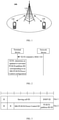
- the communication system 100 may include a network device 110, and the network device 110 may be a device that communicates with a terminal device 120 (or called a communication terminal or a terminal).
- the network device 110 may provide communication coverage for a specific geographic area, and may communicate with terminal devices located in the coverage area.
- the network device 110 may be a base station (Base Transceiver Station, BTS) in a GSM system or a CDMA system, may also be a base station (NodeB, NB) in a WCDMA system, or an evolved base station (Evolutional Node B, eNB or eNodeB) in an LTE system, or a wireless controller in a cloud radio access network (Cloud Radio Access Network, CRAN), or the network device can be a mobile switching center, a relay station, an access point, a vehicle-mounted device, a wearable device, a hub, a switch, a bridge, a router, a network side device in a 5G network, or a network device in a future evolution of a public land mobile network (Public Land Mobile Network, PLMN), etc.
- BTS Base Transceiver Station
- NB base station
- Evolutional Node B, eNB or eNodeB evolved base station
- CRAN Cloud Radio Access Network
- the network device can be a mobile
- the communication system 100 also includes at least one terminal device 120 located within the coverage area of the network device 110.
- a terminal device includes, but is not limited to, connection via a wired line, such as connection via a public switched telephone network (Public Switched Telephone Networks, PSTN), a digital subscriber line (Digital Subscriber Line, DSL), a digital cable, and a direct cable; and/or another data connection/network; and/or via a wireless interface, such as for a cellular network, a wireless local area network (Wireless Local Area Network, WLAN), a digital TV network such as a DVB-H network, a satellite network, an AM-FM broadcast transmitter; and/or an apparatus of another terminal device that is set to receive/transmit communication signals; and/or an internet of things (Internet of Things, IoT) device.
- PSTN Public Switched Telephone Networks
- DSL Digital Subscriber Line
- WLAN wireless Local Area Network
- WLAN wireless local area network
- TV network such as a DVB-H network
- satellite network such as
- a terminal device set to communicate through a wireless interface may be referred to as a "wireless communication terminal", a “wireless terminal” or a “mobile terminal”.
- mobile terminals include, but are not limited to, satellites or cellular phones; personal communications system (Personal Communications System, PCS) terminals that can combine cellular radio phones with data processing, fax, and data communication capabilities; can include radio phones, pagers, internet/intranet access, Web browser, memo pad, calendar, and/or a PDA of a global positioning system (Global Positioning System, GPS) receiver; and a conventional laptop and/or a palmtop receiver or other electronic devices including radio telephone transceivers.
- PCS Personal Communications System
- GPS Global Positioning System
- the terminal device can refer to an access terminal, a user equipment (User Equipment, UE), a user unit, a user station, a mobile station, a mobile platform, a remote station, a remote terminal, a mobile device, a user terminal, a terminal, a wireless communication device, a user agent, or a user apparatus.
- UE User Equipment
- An access terminal can be a cellular phone, a cordless phone, a session initiation protocol (Session Initiation Protocol, SIP) phone, a wireless local loop (Wireless Local Loop, WLL) station, a personal digital processing (Personal Digital Assistant, PDA), and a functional handheld device with wireless communication functions, a computing device or other processing devices connected to wireless modems, a vehicle-mounted device, a wearable device, a terminal device in a 5G network, or a terminal device in a future evolution of PLMN, etc.
- SIP Session Initiation Protocol
- WLL Wireless Local Loop
- PDA Personal Digital Assistant
- device to device (Device to Device, D2D) communication can be performed between the terminal devices 120.
- D2D Device to Device
- the 5G system or the 5G network may also be referred to as a new radio (New Radio, NR) system or a NR network.
- NR New Radio
- FIG. 1 exemplarily shows one network device and two terminal devices.
- the communication system 100 may include multiple network devices and a coverage of each network device may include other numbers of terminal devices, which is not limited in the embodiments of the present application.
- the communication system 100 may also include other network entities such as a network controller and a mobility management entity, which are not limited in the embodiments of the present application.
- network entities such as a network controller and a mobility management entity, which are not limited in the embodiments of the present application.
- a device with a communication function in the network/system in the embodiment of the present application may be referred to as a communication device.
- the communication device may include a network device 110 with a communication function and a terminal device 120.
- the network device 110 and the terminal device 120 may be the specific devices described above, which will not be repeated here.
- the communication device may also include other devices in the communication system 100, such as network controllers, mobility management entities, and other network entities, which are not limited in the embodiments of the application.
- the embodiments of the present application provide a method for activating or updating a pathloss RS of a physical uplink shared channel PUSCH, where indications can be implemented through a medium access control (medium access control, MAC) control element (control element, CE).
- medium access control medium access control
- CE control element
- FIG. 2 is a schematic flowchart of a method 200 for activating or updating a pathloss RS of a physical uplink shared channel PUSCH according to an embodiment of the present application.
- the method 200 includes: S210, transmitting a MAC CE, that is, a network device transmits a MAC CE to a terminal device.
- the MAC CE includes at least one SRI-PUSCH-Power Control field and/or at least one PUSCH-pathloss RS field
- the at least one SRI-PUSCH-Power Control field is used to indicate at least one SRI-PUSCH-Power Control configuration (configuration)
- the at least one PUSCH-pathloss RS field is used to indicate at least one PUSCH-pathloss RS corresponding to the at least one SRI-PUSCH-Power Control configuration.
- a type of the above-mentioned MAC CE can be distinguished by a logical channel identifier (logical channel identifier, LCID).
- a header of a MAC subPDU or a header of a MAC protocol data unit (Protocol Data Unit, PDU) where the MAC CE is located includes an LCID field, and the LCID field is used to indicate a type of the MAC CE.
- a value of an LCID used to indicate a type of the MAC CE in the embodiments of the present application can be set according to actual applications. For example, any value between 33 and 46 can be selected, but the embodiments of the present application are not limited thereto.
- the MAC CE may further include a serving cell (Serving Cell) identifier field, where the serving cell identifier field is used to indicate an ID of a serving cell where the terminal device resides.
- a size of the serving cell identifier field can be set according to the maximum number of serving cells. For example, if the maximum number of serving cells is 32, then the corresponding serving cell identifier field occupies 5 bits (bits).
- the MAC CE further includes a bandwidth part (bandwidth part, BWP) identifier field, where the bandwidth part identifier field is used to indicate a BWP ID corresponding to the terminal device.
- BWP bandwidth part
- a size of the bandwidth part identifier field can be set according to the maximum number of bandwidth parts. For example, if the maximum number of the bandwidth part is 4, then the corresponding bandwidth part identifier field occupies 2 bits.
- the MAC CE may also include a reserved bit represented as "R", however, the embodiments of the present application are not limited thereto.
- the method 200 in the embodiment of the present application may be executed by a terminal device and a network device.
- the terminal device may be the terminal device shown in FIG. 1
- the network device may be the network device shown in FIG. 1 , but the embodiments of the present application are not limited thereto.
- the method 200 further includes: S220, determining an updated or activated PUSCH-pathloss RS corresponding to an SRI-PUSCH-Power Control configuration.
- the terminal device receives the MAC CE transmitted by the network device, and updates or activates, according to the MAC CE, the at least one PUSCH-pathloss RS corresponding to the at least one SRI-PUSCH-Power Control configuration indicated by the MAC CE.
- the network device can configure one or more SRI-PUSCH-Power Control configurations for the terminal device, and can also configure one or more PUSCH-pathloss RSs, and there is a corresponding relationship between the SRI-PUSCH-Power Control configuration and the PUSCH-pathloss RS.
- the maximum number of the SRI-PUSCH-Power Control configurations is usually 16, and the maximum number of the PUSCH-pathloss RSs is usually 8 or 16, or it can also be 32 or 64; in addition, one SRI-PUSCH -Power Control configuration usually corresponds to one PUSCH-pathloss RS, but there may be multiple SRI-PUSCH-Power Control configurations corresponding to the same PUSCH-pathloss RS, that is, one PUSCH-pathloss RS may correspond to one or more SRI-PUSCH-Power Control configuration, but the embodiments of the present application are not limited thereto.
- the network device may configure the one or more SRI-PUSCH-Power Control configurations and/or configure one or more PUSCH-pathloss RSs for the terminal device through an RRC message, or the network device may also configure a corresponding relationship between the SRI-PUSCH-Power Control configuration and the PUSCH-pathloss RS for the terminal device through an RRC message, but the embodiments of the present application are not limited thereto.
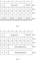
- At least one SRI-PUSCH-Power Control field and/or at least one PUSCH-pathloss RS field included in the MAC CE may be set in different ways. In the following, various situations will be described in detail with reference to FIG. 3 to FIG. 14 which show several different MAC CE formats respectively.
- the MAC CE may include at least one SRI-PUSCH-Power Control field and at least one PUSCH-pathloss RS field, and the at least one SRI-PUSCH-Power Control field corresponds to the at least one PUSCH-pathloss RS field one by one, that is, one SRI-PUSCH-Power Control field corresponds to one PUSCH-pathloss RS field, and one SRI-PUSCH-Power Control field in the at least one SRI-PUSCH-Power Control field is used to indicate an identifier (ID) (or can also be referred to as an SRI-PUSCH-Power Control ID) of one SRI-PUSCH-Power Control configuration in the at least one SRI-PUSCH-Power Control configuration, one PUSCH-pathloss RS field in the at least one PUSCH-pathloss RS field is used to indicate an ID of one PUSCH-pathloss RS in the at least one PUSCH-pathloss RS.
- ID an identifier
- At least one PUSCH-pathloss RS field in the MAC CE may include multiple PUSCH-pathloss RS fields which include an ID of the same PUSCH-pathloss RS.
- the size of each SRI-PUSCH-Power Control field is related to the number of SRI-PUSCH-Power Control configurations
- the size of each PUSCH-pathloss RS field is related to the number of PUSCH-pathloss RSs.
- the method 200 may further include: the terminal device determines the size of each SRI-PUSCH-Power Control field in the at least one SRI-PUSCH-Power Control field according to the number of the at least one SRI-PUSCH-Power Control configuration. For example, as shown in FIG. 3 to FIG. 6 , it is assumed that the maximum number of the at least one SRI-PUSCH-Power Control configuration is 16, then each SRI-PUSCH-Power Control field occupies 4 bits.
- the method 200 may further include: the terminal device determines the size of each PUSCH-pathloss RS field in the at least one PUSCH-pathloss RS field according to the number of the at least one PUSCH-pathloss RS field. For example, as shown in FIG. 3 and FIG. 5 , it is assumed that the maximum number of the at least one PUSCH-pathloss RS is 4, then each PUSCH-pathloss RS field occupies 2 bits; for another example, it is assumed that the maximum number of the at least one PUSCH-pathloss RS is 8, then each PUSCH-pathloss RS field occupies 3 bits; for another example, as shown in FIG. 4 and FIG. 6 , it is assumed that the maximum number of the at least one PUSCH-pathloss RS is 16, then each PUSCH-pathloss RS field occupies 4 bits, and so on.
- one SRI-PUSCH-Power Control field corresponds to one PUSCH-pathloss RS field, so for any one of MCA CEs, said MAC CE can be used to indicate a PUSCH-pathloss RS corresponding to one or more SRI-PUSCH-Power Control configurations. For example, as shown in FIG. 3 and FIG.
- a MAC CE can only be used to indicate one PUSCH-pathloss RS corresponding to one SRI-PUSCH-Power Control configuration
- the MCA CE includes an SRI-PUSCH-Power Control field and a PUSCH-pathloss RS field
- the SRI-PUSCH-Power Control field includes an ID of the SRI-PUSCH-Power Control configuration
- the PUSCH-pathloss RS field includes an ID of the PUSCH-pathloss RS corresponding to the SRI-PUSCH-Power Control configuration
- the terminal device determines, according to the MCA CE, the PUSCH-pathloss RS corresponding to an SRI-PUSCH-Power Control configuration that needs to be activated or updated. If it is necessary to activate or update PUSCH-pathloss RSs corresponding to multiple SRI-PUSCH-Power Control configurations, multiple MAC CEs can be transmitted to the terminal device.
- a MCA CE can also be used to indicate PUSCH-pathloss RSs corresponding to multiple SRI-PUSCH-Power Control configurations, then the MCA CE includes multiple SRI-PUSCH-Power Control fields and multiple PUSCH-pathloss RS fields, where an SRI-PUSCH-Power Control field includes an ID of an SRI-PUSCH-Power Control configuration, and a corresponding PUSCH-pathloss RS field includes an ID of a PUSCH-pathloss RS corresponding to the SRI-PUSCH-Power Control configuration. It is assumed that the MCA CE includes N octets (Oct) as shown in FIG. 5 and FIG.
- the MCA CE can be used to indicate at least N-1 SRI-PUSCH-Power Control configurations and their corresponding PUSCH-pathloss RSs, so that the terminal device can update or activate the PUSCH-pathloss RSs corresponding to the N-1 SRI-PUSCH-Power Control configurations according to the MCA CE.
- this MAC CE specifically includes multiple SRI-PUSCH-Power Control fields, and the multiple SRI-PUSCH-Power Control fields correspond to multiple SRI-PUSCH-Power Control configurations configured for the terminal device one by one.
- Each SRI-PUSCH-Power Control field in the multiple SRI-PUSCH-Power Control fields is used to indicate whether a PUSCH-pathloss RS of a corresponding SRI-PUSCH-Power Control configuration needs to be updated or activated, that is, each SRI-PUSCH-Power Control field is not the ID of the SRI-PUSCH-Power Control configuration in the first embodiment.
- an SRI-PUSCH-Power Control field represented as a first value in the multiple SRI-PUSCH-Power Control fields is the at least one SRI-PUSCH-Power Control field, that is, if a certain SRI-PUSCH-Power Control field in the multiple SRI-PUSCH-Power Control fields is a first value, then said SRI-PUSCH-Power Control field belongs to the at least one SRI-PUSCH-Power Control field in the aforementioned S210, that is, a PUSCH-pathloss RS of an SRI-PUSCH-Power Control configuration corresponding to said SRI-PUSCH-Power Control field needs to be updated or activated; on the contrary, if a certain SRI-PUSCH-Power Control field in the multiple SRI-PUSCH-Power Control fields is not the first value, then this SRI-PUSCH-Power Control field does not belong to the at least one SRI-PUSCH-Power Control field in the aforementioned S210, that is, a PUSCH-pathloss RS of an SRI-PUSCH-Power Control
- the network device can configure multiple SRI-PUSCH-Power Control configurations for the terminal device, and multiple SRI-PUSCH-Power Control fields which correspond to the multiple SRI-PUSCH-Power Control configurations one by one can be set. Some or all of the multiple SRI-PUSCH-Power Control fields belong to the at least one SRI-PUSCH-Power Control field in the aforementioned S210, then in the MAC CE, the at least one PUSCH-pathloss RS field is set corresponding to the at least one SRI-PUSCH-Power Control field one by one, where a PUSCH-pathloss RS field in the at least one PUSCH-pathloss RS field is used to indicate an ID of a PUSCH-pathloss RS in the at least one PUSCH-pathloss RS.
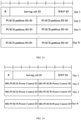
- the method 200 may further include: the terminal device determines the size of each PUSCH-pathloss RS field in the at least one PUSCH-pathloss RS field according to the number of the at least one PUSCH-pathloss RS field. For example, as shown in FIG. 7 , it is assumed that the maximum number of the at least one PUSCH-pathloss RS is 4, then each PUSCH-pathloss RS field occupies 2 bits; for another example, as shown in FIG.
- each PUSCH-pathloss RS field occupies 6 bits; for another example, as shown in FIG. 9 , it is assumed that the maximum number of at least one PUSCH-pathloss RS is 8, then each PUSCH-pathloss RS field occupies 3 bits, and so on.
- each SRI-PUSCH-Power Control field in the multiple SRI-PUSCH-Power Control fields is used to indicate whether the PUSCH-pathloss RS of the corresponding SRI-PUSCH-Power Control configuration needs to be updated or activated. Therefore, each SRI-PUSCH-Power Control field can be set to occupy simply 1 bit.
- each SRI-PUSCH-Power Control field in the multiple SRI-PUSCH-Power Control fields is "1" it means that the SRI-PUSCH-Power Control field is a first value, that is, the PUSCH-pathloss RS of the SRI-PUSCH-Power Control configuration corresponding to this SRI-PUSCH-Power Control field needs to be updated or activated, and a PUSCH-pathloss RS field corresponding to this SRI-PUSCH-Power Control field is set in the MAC CE, so as to indicate an ID of the updated or activated PUSCH-pathloss RS; on the contrary, if a certain SRI-PUSCH-Power Control field is "0", it means that the SRI-PUSCH-Power Control field is not a first value, that is, the PUSCH-pathloss RS of the SRI-PUSCH-Power Control configuration corresponding to the SRI-PUSCH-Power Control field does not need to be updated or activated.
- the multiple SRI-PUSCH-Power Control fields in the MAC CE in the second embodiment may be contiguous or non-contiguous. Specifically, as a first case, the multiple SRI-PUSCH-Power Control fields may be contiguous.
- the MAC CE may include an SRI-PUSCH-Power Control bitmap.
- the aforementioned multiple SRI-PUSCH-Power Control fields in the second embodiment are consecutive multiple bits included in the SRI-PUSCH-Power Control bitmap.
- an SRI-PUSCH-Power Control bitmap included in the MCA CE can be set to 16 bits, i.e., S 0 to S 15 in Oct2 and Oct3 shown in FIG. 7 and FIG. 8 , each bit represents an SRI-PUSCH-Power Control field correspondingly, and the MCA CE includes a total of 16 SRI-PUSCH-Power Control fields.
- the arrangement of these 16 SRI-PUSCH-Power Control fields may be as shown in FIG. 7 or FIG. 8 , or other arrangements may also be used, and the embodiments of the present application are not limited thereto.
- At least one SRI-PUSCH-Power Control field whose bit value is "1" in a bitmap formed by the 16 SRI-PUSCH-Power Control fields at least one PUSCH-pathloss RS field is correspondingly set thereafter one by one, each PUSCH-pathloss RS field includes an ID of a PUSCH-pathloss RS, so as to indicate that the terminal device updates or activates the PUSCH-pathloss RS.
- a value of S 3 is "1”
- a PUSCH-pathloss RS field is set corresponding to the S 3 .
- the PUSCH-pathloss RS field includes an ID of a PUSCH-pathloss RS, the ID of the PUSCH-pathloss RS of the SRI-PUSCH-Power Control configuration corresponding to the S 3 is updated or activated by the terminal device.
- the PUSCH-pathloss RS field may not be set, or, the PUSCH-pathloss RS field may also be set, but the terminal device does not need to activate or update an ID of an PUSCH-pathloss RS carried therein.
- the PUSCH-pathloss RS field is not set, that is, a value of a certain bit in the SRI-PUSCH-Power Control bitmap is not a first value, a PUSCH-pathloss RS field corresponding thereto is not set, then the size of the MAC CE depends on the number of PUSCH-pathloss RSs, of the SRI-PUSCH-Power Control configurations, that need to be updated or activated by the terminal device.
- the multiple SRI-PUSCH-Power Control fields may also be non-contiguous.
- the MAC CE includes multiple SRI-PUSCH-Power Control fields, in addition, it also includes multiple PUSCH-pathloss RS fields, the multiple PUSCH-pathloss RS fields correspond to the multiple SRI-PUSCH-Power Control fields one by one.
- a first PUSCH-pathloss RS field in the multiple PUSCH-pathloss RS fields corresponds to a first SRI-PUSCH-Power Control field in the multiple SRI-PUSCH-Power Control fields
- the first PUSCH-pathloss RS field and the first SRI-PUSCH-Power Control field are contiguous
- the first SRI-PUSCH-Power Control field is any one of the multiple SRI-PUSCH-Power Control fields
- the first PUSCH-pathloss RS field is a field in the multiple PUSCH-pathloss RS fields corresponding to the first SRI-PUSCH-Power Control field.
- the first SRI-PUSCH-Power Control field is used to indicate whether the first PUSCH-pathloss RS of the corresponding first SRI-PUSCH-Power Control configuration needs to be activated or updated by the terminal device, and the first PUSCH-pathloss RS field is used to indicate an ID of the first PUSCH-pathloss RS, that is, the first PUSCH-pathloss RS corresponds to the first SRI-PUSCH-Power Control configuration corresponding to the first SRI-PUSCH-Power Control field.
- the size of the MAC CE depends on the number of SRI-PUSCH-Power Control configurations configured by the network device for the terminal device. If the number of SRI-PUSCH-Power Control configurations is fixed, then the size of the MAC CE is fixed.
- the MAC CE can be set with 16 SRI-PUSCH-Power Control fields, which are represented as S 0 to S 15 in FIG. 9 respectively, each SRI-PUSCH-Power Control field corresponds to a PUSCH-pathloss RS field, that is, the MAC CE has 16 PUSCH-pathloss RS fields.
- a certain SRI-PUSCH-Power Control field in the 16 SRI-PUSCH-Power Control fields is "1"
- the terminal device obtains an ID of a PUSCH-pathloss RS in a PUSCH-pathloss RS field after the S 1 , and the PUSCH-pathloss RS indicated by this ID is the PUSCH-pathloss RS of the SRI-PUSCH-Power Control configuration corresponding to the S 1 which needs to be activated or updated by the terminal device.
- the MAC CE includes at least one SRI-PUSCH-Power Control field and at least one PUSCH-pathloss RS field, however, different from the previous two embodiments, it is assumed here that among multiple SRI-PUSCH-Power Control configurations configured by the network device for the terminal device, the situation where multiple SRI-PUSCH-Power Control configurations corresponding to the same PUSCH-pathloss RS no longer exists, that is, one PUSCH-pathloss RS has at most one SRI-PUSCH-Power Control configuration corresponds thereto, for example, multiple SRI-PUSCH-Power Control configurations can correspond to multiple PUSCH-pathloss RSs one by one, then refer to the second embodiment for the setting of multiple SRI-PUSCH-Power Control fields, multiple PUSCH-pathloss RS fields can also be set.
- the SRI-PUSCH-Power Control fields can be a bitmap.
- the PUSCH-pathloss RS fields can be a bitmap.
- the MAC CE may include multiple PUSCH-pathloss RS fields, and the multiple PUSCH-pathloss RS fields correspond to multiple PUSCH-pathloss RSs configured by the network device for the terminal device one by one, and each PUSCH-pathloss RS field is used to indicate whether the corresponding PUSCH-pathloss RS needs to be updated or activated.
- the multiple PUSCH-pathloss RS fields may be a PUSCH-pathloss RS bitmap, and multiple bits included in the PUSCH-pathloss RS bitmap correspond to the multiple PUSCH-pathloss RSs configured by the network device for the terminal device one by one.
- Each bit in the PUSCH-pathloss RS bitmap is used to indicate whether the corresponding PUSCH-pathloss RS needs to be updated or activated. That is, if a certain PUSCH-pathloss RS field in the multiple PUSCH-pathloss RS fields is a first value, then the PUSCH-pathloss RS field belongs to the at least one PUSCH-pathloss RS field in the aforementioned S210, that is, a PUSCH-pathloss RS of an SRI-PUSCH-Power Control configuration corresponding to this PUSCH-pathloss RS field needs to be updated or activated; on the contrary, if a certain PUSCH-pathloss RS field in the multiple PUSCH-pathloss RS fields is not the first value, then this PUSCH-pathloss RS field does not belong to the at least one PUSCH-pathloss RS field in the aforementioned S210, that is, a PUSCH-pathloss RS of an SRI
- the network device can configure multiple PUSCH-pathloss RSs for the terminal device, and multiple PUSCH-pathloss RS fields are set corresponding to the multiple PUSCH-pathloss RSs one by one. Some or all of the multiple PUSCH-pathloss RS fields may belong to the at least one PUSCH-pathloss RS field, then in the MAC CE, at least one SRI-PUSCH-Power Control field is set corresponding to the at least one PUSCH-pathloss RS field one by one, where an SRI-PUSCH-Power Control field in the at least one SRI-PUSCH-Power Control field is used to indicate an ID of an SRI-PUSCH-Power Control configuration in the at least one SRI-PUSCH-Power Control configuration.
- the size of each SRI-PUSCH-Power Control field is then related to the number of SRI-PUSCH-Power Control configurations.
- the method 200 may further include: the terminal device determines the size of each SRI-PUSCH-Power Control field in the at least one SRI-PUSCH-Power Control field according to the number of the at least one SRI-PUSCH-Power Control configuration. For example, as shown in FIG. 10 and FIG. 11 , it is assumed that the maximum number of the at least one SRI-PUSCH-Power Control configuration is 16, then each SRI-PUSCH-Power Control field occupies 4 bits.
- each PUSCH-pathloss RS field in the multiple PUSCH-pathloss RS fields is used to indicate whether the PUSCH-pathloss RS of the corresponding SRI-PUSCH-Power Control configuration needs to be updated or activated. Therefore, each PUSCH-pathloss RS field can only be set to occupy 1 bit. For example, if a certain PUSCH-pathloss RS field is "1", it means that the PUSCH-pathloss RS field is the first value, then the MAC CE is set with an SRI-PUSCH-Power Control field corresponding to the PUSCH-pathloss RS field.
- the SRI-PUSCH-Power Control field includes an ID of an SRI-PUSCH-Power Control configuration.
- a PUSCH-pathloss RS of the SRI-PUSCH-Power Control configuration indicated by this ID needs to be updated or activated; on the contrary, if a certain PUSCH-pathloss RS field is "0", it means that the PUSCH-pathloss RS field is not the first value, that is, a PUSCH-pathloss RS of an SRI-PUSCH-Power Control configuration corresponding to this PUSCH-pathloss RS field does not need to be updated or activated.
- each PUSCH-pathloss RS field in the multiple PUSCH-pathloss RS fields may also be set to occupy multiple bits, and the embodiments of the present application are not limited thereto.
- the multiple PUSCH-pathloss RS fields in the MAC CE may be contiguous or non-contiguous.
- the multiple SRI-PUSCH-Power Control fields are contiguous, that is, the MAC CE may include a PUSCH-pathloss RS bitmap, and the multiple PUSCH-pathloss RS fields are consecutive multiple bits included in the PUSCH-pathloss RS bitmap.
- the terminal device has at most 16 PUSCH-pathloss RSs, and these 16 PUSCH-pathloss RSs correspond to 16 SRI-PUSCH-Power Control configurations one by one, then correspondingly, the PUSCH-pathloss RS bitmap included in the MCA CE can be set to 16 bits, that is, S 0 to S 15 in Oct2 and Oct3 as shown in FIG. 10 . Each bit represents a PUSCH-pathloss RS field correspondingly.
- the MCA CE includes a total of 16 PUSCH-pathloss RS fields. Or, as shown in FIG.
- the terminal device has at most 8 PUSCH-pathloss RSs, and the 8 PUSCH-pathloss RSs correspond to 8 SRI-PUSCH-Power Control configurations one by one, then correspondingly, the bitmap of the PUSCH-pathloss RSs included in the MCA CE can be set to 8 bits, that is, S 0 to S 7 in Oct2 as shown in FIG. 11 . Each bit represents a PUSCH-pathloss RS field correspondingly.
- the MCA CE includes a total of 8 PUSCH-pathloss RS fields.
- the arrangement of these 16 PUSCH-pathloss RS fields may be as shown in FIG. 10
- the arrangement of these 8 PUSCH-pathloss RS fields may be as shown in FIG. 11 , or other arrangements may also be used, and the embodiments of the present application are not limited thereto.
- each SRI-PUSCH-Power Control field includes an ID of an SRI-PUSCH-Power Control configuration, which indicates that the terminal device updates or activates a PUSCH-pathloss RS corresponding to the SRI-PUSCH-Power Control configuration. For example, it is assumed that a value of S 3 is " 1", then an SRI-PUSCH-Power Control field is set corresponding to the S 3 .
- the SRI-PUSCH-Power Control field includes an ID of an SRI-PUSCH-Power Control configuration.
- the ID of the PUSCH-pathloss RS of the SRI-PUSCH-Power Control configuration updated or activated by the terminal device is the PUSCH-pathloss RS corresponding to the S 3 .
- the SRI-PUSCH-Power Control field may not be set, or, the SRI-PUSCH-Power Control field may also be set, but the terminal device does not need to activate or update an ID of a PUSCH-pathloss RS of an SRI-PUSCH-Power Control configuration indicated by this SRI-PUSCH-Power Control field.
- the SRI-PUSCH-Power Control field is not set, that is, when a value of a bit in the PUSCH-pathloss RS bitmap is not a first value, an SRI-PUSCH-Power Control field corresponding thereto is not set, then the size of the MAC CE depends on the number of PUSCH-pathloss RSs, of the SRI-PUSCH-Power Control configurations, that need to be updated or activated by the terminal device.
- multiple PUSCH-pathloss RS fields in the MAC CE may also be non-contiguous. Specifically, reference may be made to the second case in the second embodiment for the setting, which is not described herein again for brevity.
- the MAC CE includes at least one SRI-PUSCH-Power Control field and at least one PUSCH-pathloss RS field, however, different from the foregoing three embodiments, the at least one SRI-PUSCH-Power Control field included in this MAC CE corresponds to the at least one PUSCH-pathloss RS field one by one, where each PUSCH-pathloss RS field is a PUSCH-pathloss RS bitmap.
- a first PUSCH-pathloss RS field is any one of the multiple PUSCH-pathloss RS fields
- a first SRI-PUSCH-Power Control field is any one of the multiple SRI-PUSCH-Power Control fields
- the first SRI-PUSCH-Power Control field corresponds to the first PUSCH-pathloss RS field.
- the first SRI-PUSCH-Power Control field is used to indicate an ID of the first SRI-PUSCH-Power Control configuration in the at least one SRI-PUSCH-Power Control configuration
- the first PUSCH-pathloss RS field is a bitmap, which is referred to as a first PUSCH-pathloss RS bitmap here.
- Multiple bits included in the first PUSCH-pathloss RS bitmap correspond to multiple PUSCH-pathloss RSs configured for the terminal device one by one.
- One or more first bits in the first PUSCH-pathloss RS bitmap satisfy: a value of the first bit is a first value, and a PUSCH-pathloss RS corresponding to the first bit is a PUSCH-pathloss RS corresponding to the first SRI-PUSCH-Power Control configuration.
- the size of each SRI-PUSCH-Power Control field is related to the number of SRI-PUSCH-Power Control configurations.
- the method 200 may further include: the terminal device determines the size of each SRI-PUSCH-Power Control field in the at least one SRI-PUSCH-Power Control field according to the number of the at least one SRI-PUSCH-Power Control configuration. For example, as shown in FIG. 12 , it is assumed that the maximum number of the at least one SRI-PUSCH-Power Control configuration is 16, each SRI-PUSCH-Power Control field occupies 4 bits.
- the total number of bits in each bitmap of the at least one PUSCH-pathloss RS bitmap included in the MAC CE is determined by the number of PUSCH-pathloss RSs possessed by the terminal device. For example, as shown in FIG. 12 , if the maximum number of PUSCH-pathloss RSs is 8, each PUSCH-pathloss RS bitmap has 8 bits; for another example, if the maximum number of PUSCH-pathloss RSs is 16, then each PUSCH-pathloss RS bitmap has 16 bits, and so on.
- the MAC CE includes at least one SRI-PUSCH-Power Control field, and each SRI-PUSCH-Power Control field includes an ID of an SRI-PUSCH-Power Control configuration, so as to indicate that the terminal device needs to activate or update a PUSCH-pathloss RS corresponding to the at least one SRI-PUSCH-Power Control configuration.
- the first SRI-PUSCH-Power Control field includes an ID of a first SRI-PUSCH-Power Control configuration.
- a field corresponding to the first SRI-PUSCH-Power Control field is the first PUSCH-pathloss RS field.
- the first PUSCH-pathloss RS field is a bitmap, which is referred to as the first PUSCH-pathloss RS bitmap here, and it is assumed that the terminal device has 8 PUSCH-pathloss RSs, that is, as shown in Oct3 in FIG. 12 , the first PUSCH-pathloss RS bitmap has 8 bits, each bit represents a PUSCH-pathloss RS correspondingly.
- the arrangement of the at least one SRI-PUSCH-Power Control field and the corresponding PUSCH-pathloss RS field included in the MAC CE may be as shown in FIG. 12 , or may also be set in other manners, the embodiments of the present application are not limited thereto.
- the MAC CE includes two types of fields (the SRI-PUSCH-Power Control field and the PUSCH-pathloss RS field). However, the MAC CE may only include one type of the SRI-PUSCH-Power Control field and the PUSCH-pathloss field.
- the MAC CE may include a PUSCH-pathloss RS field, but does not include an SRI-PUSCH-Power Control field.
- the MAC CE may include multiple PUSCH-pathloss RS fields, and the multiple PUSCH-pathloss RS fields correspond to multiple SRI-PUSCH-Power Control configurations and PUSCH-pathloss RSs configured for the terminal device one by one.
- one SRI-PUSCH-Power Control configuration corresponds to only one PUSCH-pathloss RS
- the multiple PUSCH-pathloss RS fields corresponding to the multiple SRI-PUSCH-Power Control configurations can be arranged according to a specific order of the multiple SRI-PUSCH-Power Control configurations configured for terminal device, then a PUSCH-pathloss RS field in the multiple PUSCH-pathloss RS fields is used to indicate an ID of a PUSCH-pathloss RS of a corresponding SRI-PUSCH-Power Control configuration; in addition, the method 200 may further include: the terminal device determines, according to the ID of the PUSCH-pathloss RS indicated by each PUSCH-pathloss RS field in the multiple PUSCH-pathloss RS fields, whether to update or activate the PUSCH-pathloss RS of the SRI-PUSCH Power Control configuration corresponding to each PUSCH-pathloss RS field.
- each PUSCH-pathloss RS field includes an ID of a PUSCH-pathloss RS
- the size of each PUSCH-pathloss RS field is thus related to the number of PUSCH-pathloss RSs.
- the method 200 may further include: the terminal device determines the size of each PUSCH-pathloss RS field in the at least one PUSCH-pathloss RS field according to the number of the at least one PUSCH-pathloss RS field. For example, it is assumed that the maximum number of the at least one PUSCH-pathloss RS is 8, then each PUSCH-pathloss RS field occupies 3 bits; for another example, as shown in FIG. 13 , it is assumed that the maximum number of the at least one PUSCH-pathloss RS is 16, then each PUSCH-pathloss RS field occupies 4 bits, and so on.
- multiple PUSCH-pathloss RS fields are correspondingly set according to multiple SRI-PUSCH-Power Control configurations possessed by the terminal device, and each PUSCH-pathloss RS field corresponds to an SRI-PUSCH-Power Control configuration, and each PUSCH-pathloss RS field includes an ID of a PUSCH-pathloss RS of its corresponding SRI-PUSCH-Power Control configuration, then the terminal device can determine, according to the ID of the PUSCH-pathloss RS included in each PUSCH-pathloss RS field, whether a PUSCH-pathloss RS corresponding to each SRI-PUSCH-Power Control configuration needs to be updated or activated.
- an ID of a PUSCH-pathloss RS included in the PUSCH-pathloss RS field corresponding to a certain SRI-PUSCH-Power Control configuration changes, it means that the terminal device needs to activate the PUSCH-pathloss RS of the SRI-PUSCH-Power Control configuration corresponding to the PUSCH-pathloss RS field.
- the MAC CE may further include an SRI-PUSCH-Power Control field, but does not include a PUSCH-pathloss RS field.
- SRI-PUSCH-Power Control field but does not include a PUSCH-pathloss RS field.
- the multiple SRI-PUSCH-Power Control configurations configured for the terminal device correspond to multiple PUSCH-pathloss RSs one by one
- the MAC CE may include multiple SRI-PUSCH-Power Control fields
- the multiple SRI-PUSCH-Power Control fields correspond to the multiple SRI-PUSCH-Power Control configurations and PUSCH-pathloss RSs configured for the terminal device one by one.
- the method 200 may further include: the terminal device determines, according to the ID of the SRI-PUSCH-Power Control configuration indicated by each SRI-PUSCH-Power Control field in the multiple SRI-PUSCH-Power Control fields, whether to update or activate a PUSCH-pathloss RS of the SRI-PUSCH-Power Control configuration corresponding to the each SRI-PUSCH-Power Control field.
- IDs of SRI-PUSCH-Power Control configurations included in the multiple SRI-PUSCH-Power Control fields may be the same, that is, the multiple PUSCH-pathloss RSs corresponding to the multiple SRI-PUSCH-Power Control fields correspond to the same SRI-PUSCH-Power Control configuration.
- the size of each SRI-PUSCH-Power Control field is related to the number of SRI-PUSCH-Power Control configurations.
- the method 200 may further include: the terminal device determines the size of each SRI-PUSCH-Power Control field in the at least one SRI-PUSCH-Power Control field according to the number of the at least one SRI-PUSCH-Power Control configuration. For example, as shown in FIG. 14 , it is assumed that the maximum number of the at least one SRI-PUSCH-Power Control configuration is 16, then each SRI-PUSCH-Power Control field occupies 4 bits.
- each SRI-PUSCH-Power Control field corresponds to a PUSCH-pathloss RS
- each SRI-PUSCH-Power Control field includes an ID of its corresponding SRI-PUSCH-Power Control configuration
- the terminal device can determines, according to an ID of an SRI-PUSCH-Power Control configuration included in each SRI-PUSCH-Power Control field and a PUSCH-pathloss RS corresponding to each SRI-PUSCH-Power Control field, whether a PUSCH-pathloss RS corresponding to each SRI-PUSCH-Power Control configuration needs to be updated or activated.
- an ID of an SRI-PUSCH-Power Control configuration included in an SRI-PUSCH-Power Control field corresponding to a certain PUSCH-pathloss RS changes, it means that the terminal device needs to activate a PUSCH-pathloss RS of the SRI-PUSCH Power Control configuration corresponding to the SRI-PUSCH-Power Control field.
- a variety of different MAC CE formats can be set flexibly, and a PUSCH-pathloss RS ID corresponding to an SRI-PUSCH-Power Control configuration can be activated or updated based on this MAC CE, thereby reducing the transmission delay significantly.
- the method for activating or updating the pathloss reference signal corresponding to the sounding reference signal is described in detail above with reference to FIG. 1 to FIG. 14 .
- a terminal device and a network device will be described below with reference to FIG. 15 to FIG. 19 according to the embodiments of the present application.
- a terminal device 300 includes: a processing unit 310 and a transceiving unit 320.
- the transceiving unit 320 is configured to receive a MAC CE transmitted by a network device, where the MAC CE includes at least one SRI-PUSCH-Power Control field and/or at least one pathloss RS field, and the at least one SRI-PUSCH-Power Control field is used to indicate at least one SRI-PUSCH-Power Control configuration, and the at least one pathloss RS field is used to indicate at least one pathloss RS corresponding to the at least one SRI-PUSCH-Power Control configuration; and the processing unit 310 is configured to update or activate the at least one pathloss RS corresponding to the at least one SRI-PUSCH-Power Control configuration according to the MAC CE.
- the MAC CE includes the at least one SRI-PUSCH-Power Control field and the at least one pathloss RS field.
- the at least one SRI-PUSCH-Power Control field corresponds to the at least one pathloss RS field one by one
- an SRI-PUSCH-Power Control field in the at least one SRI-PUSCH-Power Control field is used to indicate an identifier of an SRI-PUSCH-Power Control configuration in the at least one SRI-PUSCH-Power Control configuration
- a pathloss RS field in the at least one pathloss RS field is used to indicate an identifier of a pathloss RS in the at least one the pathloss RS.
- the MAC CE includes multiple SRI-PUSCH-Power Control fields, and the multiple SRI-PUSCH-Power Control fields correspond to multiple SRI-PUSCH-Power Control configurations configured for the terminal device 300 one by one, each SRI-PUSCH-Power Control field in the multiple SRI-PUSCH-Power Control fields is used to indicate whether a pathloss RS of a corresponding SRI-PUSCH-Power Control configuration needs to be updated or activated, an SRI-PUSCH-Power Control field represented as a first value in the multiple SRI-PUSCH-Power Control fields is the at least one SRI-PUSCH-Power Control field, and the at least one SRI-PUSCH-Power Control field corresponds to the at least one pathloss RS field one by one, a pathloss RS field in the at least one pathloss RS field is used to indicate an identifier of a pathloss RS in the at least one pathloss RS.
- the MAC CE includes an SRI-PUSCH-Power Control bitmap, and the multiple SRI-PUSCH-Power Control fields are consecutive multiple bits included in the SRI-PUSCH-Power Control bitmap.
- the MAC CE includes multiple pathloss RS fields, the multiple pathloss RS fields correspond to the multiple SRI-PUSCH-Power Control fields one by one, and the at least one pathloss RS field in the multiple pathloss RS fields corresponds to the at least one SRI-PUSCH-Power Control field one by one, and a first pathloss RS field in the multiple pathloss RS fields corresponds to a first SRI-PUSCH-Power Control field in the multiple SRI-PUSCH-Power Control fields, the first pathloss RS field and the first SRI-PUSCH-Power Control field are contiguous, the first pathloss RS field is used to indicate an identifier of a first pathloss RS, and the first pathloss RS corresponds to a first SRI-PUSCH-Power Control configuration corresponding to the first SRI-PUSCH-Power Control field.
- the MAC CE includes a pathloss RS bitmap, multiple bits included in the RS pathloss bitmap correspond to the multiple pathloss RSs one by one, and each bit in the pathloss RS bitmap is used to indicate whether a corresponding pathloss RS needs to be updated or activated, a pathloss RS field represented as a first value in the multiple pathloss RS fields is the at least one pathloss RS field, the at least one pathloss RS field corresponds to the at least one SRI-PUSCH-Power Control field one by one, and an SRI-PUSCH-Power Control field in the at least one SRI-PUSCH-Power Control field is used to indicate an identifier of an SRI-PUSCH-Power Control configuration in the at least one SRI-PUSCH-Power Control configuration.
- the at least one SRI-PUSCH-Power Control field corresponds to the at least one pathloss RS field one by one
- a first SRI-PUSCH-Power Control field in the at least one SRI-PUSCH-Power Control field is used to indicate an identifier of a first SRI-PUSCH-Power Control configuration in the at least one SRI-PUSCH-Power Control configuration
- the first SRI-PUSCH-Power Control field corresponds to a first pathloss RS field in the at least one pathloss RS field
- the first pathloss RS field is a first pathloss RS bitmap
- multiple bits included in the first pathloss RS bitmap correspond to multiple pathloss RSs configured for the terminal device 300
- a value stored in a first bit in the first pathloss RS bitmap is a first value
- a pathloss RS corresponding to the first bit is a pathloss RS corresponding to the first SRI-PUSCH-Power Control configuration.
- the MAC CE includes multiple pathloss RS fields, and the multiple pathloss RS fields correspond to multiple SRI-PUSCH-Power Control configurations configured for the terminal device 300 one by one, a pathloss RS field in the multiple pathloss RS fields is used to indicate an identifier of a pathloss RS of a corresponding SRI-PUSCH-Power Control configuration; the processing unit 310 is further configured to: determine, according to an identifier of a pathloss RS indicated by each pathloss RS field in the multiple pathloss RS fields, whether to update or activate a pathloss RS of an SRI-PUSCH-Power Control configuration corresponding to each pathloss RS field.
- the processing unit 310 is further configured to: determine a size of each SRI-PUSCH-Power Control field in the at least one SRI-PUSCH-Power Control field according to a number of the at least one SRI-PUSCH-Power Control configuration.
- each SRI-PUSCH-Power Control field occupies 4 bits.
- the processing unit 310 is further configured to determine a size of each pathloss RS field in the at least one pathloss RS field according to a number of the at least one pathloss RS field.
- each pathloss RS field occupies 2 bits; if a maximum number of the at least one pathloss RS is 8, each pathloss RS field occupies 3 bits; or, if a maximum number of the at least one pathloss RS is 16, each pathloss RS field occupies 4 bits.
- the MAC CE further includes a serving cell identifier field, and the serving cell identifier field is used to indicate an identifier of a serving cell where the terminal device 300 resides.
- the MAC CE further includes a bandwidth part identifier field, and the bandwidth part identifier field is used to indicate an identifier of a bandwidth part corresponding to the terminal device 300.
- a header of a MAC PDU where the MAC CE is located includes a logical channel identifier field, and the logical channel identifier field is used to indicate a type of the MAC CE.
- the terminal device of the embodiments of the present application can flexibly set a variety of different MAC CE formats, and activate or update a PUSCH-pathloss RS ID corresponding to an SRI-PUSCH-Power Control configuration based on the MAC CE, so that the transmission delay is greatly reduced.
- a network device 400 includes: a processing unit 410 and a transceiving unit 420.
- the transceiving unit 420 is configured to transmit a MAC CE to a terminal device, where the MAC CE includes at least one SRI-PUSCH-Power Control field and/or at least one pathloss RS field, and the at least one SRI-PUSCH-Power Control field is used to indicate at least one SRI-PUSCH-Power Control configuration, the at least one pathloss RS field is used to indicate at least one pathloss RS corresponding to the at least one SRI-PUSCH-Power Control configuration; the MAC CE is used to indicate updating or activation of the at least one pathloss RS corresponding to the at least one SRI-PUSCH-Power Control configuration by the terminal device.
- the MAC CE includes the at least one SRI-PUSCH-Power Control field and the at least one pathloss RS field.
- the at least one SRI-PUSCH-Power Control field corresponds to the at least one pathloss RS field one by one
- an SRI-PUSCH-Power Control field in the at least one SRI-PUSCH-Power Control field is used to indicate an identifier of an SRI-PUSCH-Power Control configuration in the at least one SRI-PUSCH-Power Control configuration
- a pathloss RS field in the at least one pathloss RS field is used to indicate an identifier of a pathloss RS in the at least one pathloss RS.
- the MAC CE includes multiple SRI-PUSCH-Power Control fields, and the multiple SRI-PUSCH-Power Control fields correspond to multiple SRI-PUSCH-Power Control configurations configured by the network device 400 for the terminal device one by one, and each SRI-PUSCH-Power Control field in the multiple SRI-PUSCH-Power Control fields is used to indicate whether a pathloss RS of a corresponding SRI-PUSCH-Power Control configuration needs to be updated or activated, an SRI-PUSCH-Power Control field represented as a first value in the multiple SRI-PUSCH-Power Control fields is the at least one SRI-PUSCH-Power Control field, the at least one SRI-PUSCH-Power Control field corresponds to the at least one pathloss RS fields one by one, and a pathloss RS field in the at least one pathloss RS field is used to indicate an identifier of a pathloss RS in the at least one pathloss RS.
- the MAC CE includes an SRI-PUSCH-Power Control bitmap, and the multiple SRI-PUSCH-Power Control fields are consecutive multiple bits included in the SRI-PUSCH-Power Control bitmap.
- the MAC CE includes multiple pathloss RS fields, the multiple pathloss RS fields correspond to the multiple SRI-PUSCH-Power Control fields one by one, and the at least one pathloss RS field in the multiple pathloss RS fields corresponds to the at least one SRI-PUSCH-Power Control field one by one, and a first pathloss RS field in the multiple pathloss RS fields corresponds to a first SRI-PUSCH-Power Control field in the multiple SRI PUSCH power control fields, the first pathloss RS field and the first SRI-PUSCH-Power Control field are contiguous, and the first pathloss RS field is used to indicate an identifier of a first pathloss RS, and the first pathloss RS corresponds to a first SRI-PUSCH-Power Control configuration corresponding to the first SRI-PUSCH-Power Control field.
- the MAC CE includes a pathloss RS bitmap, and multiple bits included in the pathloss RS bitmap correspond to the multiple pathloss RSs one by one, each bit in the pathloss RS bitmap is used to indicate whether a corresponding pathloss RS needs to be updated or activated, a pathloss RS field represented as a first value in the multiple pathloss RS fields is the at least one pathloss RS field, the at least one pathloss RS field corresponds to the at least one SRI-PUSCH-Power Control field one by one, and an SRI-PUSCH-Power Control field in the at least one SRI-PUSCH-Power Control field is used to indicate an identifier of an SRI-PUSCH-Power Control configuration in the PUSCH power control configuration.
- the at least one SRI-PUSCH-Power Control field corresponds to the at least one pathloss RS field one by one
- a first SRI-PUSCH-Power Control field in the at least one SRI-PUSCH-Power Control field is used to indicate an identifier of a first SRI-PUSCH-Power Control configuration in the at least one SRI-PUSCH-Power Control configuration
- the first SRI-PUSCH-Power Control field corresponds to a first pathloss RS field in the at least one pathloss RS field
- the first pathloss RS field is a first pathloss RS bitmap
- multiple bits included in the first pathloss RS bitmap correspond to multiple pathloss RSs configured by the network device 400 for the terminal device one by one
- a value stored in a first bit in the first pathloss RS bitmap is a first value
- a pathloss RS corresponding to the first bit is a pathloss RS corresponding to the first SRI-PUSCH-Power Control configuration.
- the MAC CE includes multiple pathloss RS fields, and the multiple pathloss RS fields correspond to multiple SRI-PUSCH Power control configurations configured by the network device 400 for the terminal device one by one, a first pathloss RS field in the multiple pathloss RS fields is used to indicate an identifier of a first pathloss RS corresponding to a first SRI-PUSCH-Power Control configuration; the identifier of the first pathloss RS is used to indicate whether to update or activate the first pathloss RS of the first SRI-PUSCH-Power Control configuration corresponding to the first pathloss RS field by the terminal device.
- the processing unit 410 is configured to determine a size of each SRI-PUSCH-Power Control field in the at least one SRI-PUSCH-Power Control field according to a number of the at least one SRI-PUSCH-Power Control configuration.
- each SRI-PUSCH-Power Control field occupies 4 bits.
- the processing unit 410 is configured to determine a size of each pathloss RS field in the at least one pathloss RS field according to a number of the at least one pathloss RS field.
- each pathloss RS field occupies 2 bits; if a maximum number of the at least one pathloss RS is 8, each pathloss RS field occupies 3 bits; or, if a maximum number of the at least one pathloss RS is 16, each pathloss RS field occupies 4 bits.
- the MAC CE further includes a serving cell identifier field, and the serving cell identifier field is used to indicate an identifier of a serving cell where the terminal device resides.
- the MAC CE further includes a bandwidth part identifier field, and the bandwidth part identifier field is used to indicate an identifier of a bandwidth part corresponding to the terminal device.
- a header of a MAC protocol data unit where the MAC CE is located comprises a logical channel identifier field, and the logical channel identifier field is used to indicate a type of the MAC CE.
- each unit in the network device 400 of the embodiments of the present application are respectively intended to implement the corresponding procedures of the network device in each method in FIG. 1 to FIG. 14 , which will not be repeated herein for brevity.
- the network device of the embodiments of the present application can flexibly be set a variety of different MAC CE formats, and activate or update a PUSCH-pathloss RS ID corresponding to an SRI-PUSCH-Power Control configuration based on the MAC CE, so that the transmission delay is greatly reduced.
- FIG. 17 is a schematic structural diagram of a communication device 500 provided by an embodiment of the present application.
- the communication device 500 shown in FIG. 17 includes a processor 510, and the processor 510 can call and run a computer program from a memory to implement the method in the embodiments of the present application.
- the communication device 500 may further include a memory 520.
- the processor 510 may call and run a computer program from the memory 520 to implement the method in the embodiments of the present application.
- memory 520 may be a separate device independent of the processor 510, or may be integrated in the processor 510.
- the communication device 500 may further include a transceiver 530, and the processor 510 may control the transceiver 530 to communicate with other devices. Specifically, it may transmit information or data to other devices, or receive information or data transmitted by other devices.
- the transceiver 530 may include a transmitter and a receiver.
- the transceiver 530 may further include an antenna, and the number of antennas may be one or more.
- the communication device 500 may specifically be a network device in the embodiments of the present application, and the communication device 500 may implement a corresponding process implemented by the network device in each method of the embodiments of the present application, which is not repeated herein for brevity.
- the communication device 500 may specifically be a mobile terminal/terminal device of the embodiments of the present application, and the communication device 500 may implement a corresponding process implemented by the mobile terminal/terminal device in each method of the embodiment of the present application, which is not repeated herein for brevity.
- FIG. 18 is a schematic structural diagram of a chip of an embodiment of the present application.
- the chip 600 shown in FIG. 18 includes a processor 610, and the processor 610 can call and run a computer program from a memory to implement the method in the embodiments of the present application.
- the chip 600 may further include a memory 620.
- the processor 610 may call and run a computer program from the memory 620 to implement the method in the embodiments of the present application.
- the memory 620 may be a separate device independent of the processor 610, or may be integrated in the processor 610.
- the chip 600 may further include an input interface 630.
- the processor 610 can control the input interface 630 to communicate with other devices or chips, and specifically, can obtain information or data transmitted by other devices or chips.
- the chip 600 may further include an output interface 640.
- the processor 610 can control the output interface 640 to communicate with other devices or chips, and specifically, can output information or data to other devices or chips.
- the chip can be applied to a network device in the embodiments of the present application, and the chip can implement a corresponding process implemented by the network device in each method of the embodiments of the present application, which is not repeated herein for brevity.
- the chip can be applied to a mobile terminal/terminal device in the embodiments of the present application, and the chip can implement the corresponding process implemented by the mobile terminal/terminal device in each method of the embodiments of the present application, which is not repeated herein for brevity.
- the chip mentioned in the embodiments of the present application may also be referred to as a system-level chip, a system chip, a chip system, or a system-on-chip, etc.
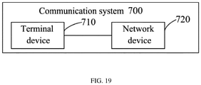
- FIG. 19 is a schematic block diagram of a communication system 700 according to an embodiment of the present application. As shown in FIG. 19 , the communication system 700 includes a terminal device 710 and a network device 720.
- terminal device 710 can be configured to implement corresponding functions implemented by the terminal device in the above method
- network device 720 can be configured to implement corresponding functions implemented by the network device in the above method, which is not repeated herein for brevity.
- the processor of the embodiments of the present application may be an integrated circuit chip with signal processing capabilities.
- the steps of the above method embodiments can be completed by hardware integrated logic circuits in the processor or instructions in the form of software.
- the above processor can be a general-purpose processor, a digital signal processor (Digital Signal Processor, DSP), an application specific integrated circuit (Application Specific Integrated Circuit, ASIC), a field programmable gate array (Field Programmable Gate Array, FPGA) or other programming logic devices, discrete gates or transistor logic devices, discrete hardware components.
- DSP Digital Signal Processor
- ASIC Application Specific Integrated Circuit
- FPGA Field Programmable Gate Array
- the methods, steps, and logical block diagrams disclosed in the embodiments of the present application can be implemented or executed.
- the general processor may be a microprocessor or the processor may also be any conventional processor or the like.
- the steps of the method disclosed in the embodiments of the present application may be directly embodied as being executed and completed by a hardware decoding processor, or executed and completed by a combination of hardware and software modules in the decoding processor.
- the software module can be located in a mature storage medium in the field, such as a random access memory, a flash memory, a read-only memory, a programmable read-only memory, or an electrically erasable programmable memory, a register or the like.
- the storage medium is located in the memory, and the processor reads information in the memory and completes the steps of the above method in combination with its hardware.
- the memory in the embodiments of the present application may be a volatile memory or a non-volatile memory, or may include both volatile and non-volatile memory.
- the non-volatile memory can be a read-only memory (Read-Only Memory, ROM), a programmable read-only memory (Programmable ROM, PROM), an erasable programmable read-only memory (Erasable PROM, EPROM), an electrically available Erase programmable read-only memory (Electrically EPROM, EEPROM) or a flash memory.
- the volatile memory may be a random access memory (Random Access Memory, RAM), which is used as an external cache.
- RAM random access memory
- SRAM static random access memory
- DRAM dynamic random access memory
- DRAM synchronous dynamic random access memory
- SDRAM double data rate SDRAM
- Enhanced SDRAM, ESDRAM enhanced synchronous dynamic random access memory
- SLDRAM synchronous link dynamic random access memory
- DRAM synchronous link dynamic random access memory
- DR RAM direct rambus RAM
- the memory in the embodiments of the present application may also be a static random access memory (static RAM, SRAM), a dynamic random access memory (dynamic RAM, DRAM), a synchronous dynamic random access memory (synchronous DRAM, SDRAM), a double data rate synchronous dynamic random access memory (double data rate SDRAM, DDR SDRAM), an enhanced synchronous dynamic random access memory (enhanced SDRAM, ESDRAM), a synchronous connection Dynamic random access memory (synch link DRAM, SLDRAM) and direct memory bus random access memory (Direct Rambus RAM, DR RAM), etc.
- static random access memory static random access memory
- DRAM dynamic random access memory
- DRAM dynamic random access memory
- SDRAM synchronous dynamic random access memory
- double data rate SDRAM double data rate SDRAM
- DDR SDRAM double data rate SDRAM
- ESDRAM enhanced synchronous dynamic random access memory
- a synchronous connection Dynamic random access memory switch link DRAM, SLDRAM
- Direct Rambus RAM Direct Rambus RAM
- the embodiments of the present application also provide a computer-readable storage medium for storing a computer program.
- the computer-readable storage medium may be applied to the network device in the embodiments of the present application, and the computer program causes a computer to execute the corresponding process implemented by the network device in each method of the embodiments of the present application, which is not repeated herein for brevity.
- the computer-readable storage medium can be applied to the mobile terminal/terminal device in the embodiments of the present application, and the computer program causes a computer to execute the corresponding process implemented by the mobile terminal/terminal device in each method of the embodiments of the present application, which is not repeated herein for brevity.
- the embodiments of the present application also provide a computer program product, including computer program instructions.
- the computer program product may be applied to the network device in the embodiments of the present application, and the computer program instructions cause a computer to execute the corresponding process implemented by the network device in each method of the embodiments of the present application, which is not repeated here for brevity.
- the computer program product can be applied to the mobile terminal/terminal device in the embodiments of the present application, and the computer program instructions cause a computer to execute the corresponding process implemented by the mobile terminal/terminal device in each method of the embodiments of the present application, which is not repeated here for brevity.
- the embodiment of the present application also provides a computer program.
- the computer program can be applied to the network device in the embodiments of the present application.
- the computer program is run on a computer, the computer is caused to execute the corresponding process implemented by the network device in each method of the embodiments of the present application, which is not repeated here for brevity.
- the computer program can be applied to the mobile terminal/terminal device in the embodiment of the present application.
- the computer program runs on a computer, the computer executes each method in the embodiments of the present application, which is not repeated here for brevity.
- the disclosed system, device, and method may be implemented in other ways.
- the device embodiments described above are only illustrative.
- the division of the units is only a logical function division, and there may be other divisions in actual implementation, for example, multiple units or components may be combined or can be integrated into another system, or some features can be ignored or not executed.
- Another point, the displayed or discussed mutual coupling or direct coupling or communication connection may be indirect coupling or communication connection through some interfaces, devices or units, and may be in electrical, mechanical or other forms.
- the units described as separate components may or may not be physically separated, and the components displayed as units may or may not be physical units, that is, they may be located in one place, or they may be distributed on multiple network units. Some or all of the units may be selected according to actual needs to achieve the objectives of the solutions of the embodiments.
- the functional units in the various embodiments of the present application may be integrated into a processing unit, or each unit may exist alone physically, or two or more units may be integrated into a unit.
- the function is implemented in the form of a software functional unit and sold or used as an independent product, it can be stored in a computer-readable storage medium.
- the technical solution of the present application essentially or the part that contributes to the prior art or a part of the technical solution can be embodied in the form of a software product, and the computer software product is stored in a storage medium, including several instructions used to cause a computer device (which may be a personal computer, a server, or a network device, etc.) to execute all or part of the steps of the methods described in the various embodiments of the present application.
- the foregoing storage medium includes: a U disk, a mobile hard disk, a read-only memory (Read-Only Memory, ROM), a random access memory (Random Access Memory, RAM), a magnetic disk or an optical disk and other mediums that can store program codes.
- ROM Read-Only Memory
- RAM Random Access Memory
Landscapes
- Engineering & Computer Science (AREA)
- Computer Networks & Wireless Communication (AREA)
- Signal Processing (AREA)
- Mobile Radio Communication Systems (AREA)
Abstract
Description
- The present application relates to the field of communications and, in particular, to a method and a device for activating or updating a PUSCH-pathloss RS.
- A network device can configure an identifier (Identifier, ID) of each space relationship information (space relationship information, SRI) physical uplink shared channel (Physical Uplink Shared Channel, PUSCH)-Power Control (Power Control) configuration (configuration) and an ID of a corresponding PUSCH-pathloss (pathloss) reference signal (Reference Signal, RS) through a radio resource control (radio resource control, RRC) message for a terminal device. At the same time, the network device can also activate or update one or more PUSCH-pathloss RSs through the RRC message.
- However, a transmission delay of the RRC message is relatively large, and how to activate or update the PUSCH-pathloss RS more quickly is a problem to be solved urgently at present.
- Embodiments of the present application provide a method and a device for activating or updating a PUSCH-pathloss RS, which can reduce transmission delays.
- In a first aspect, a method for activating or updating a PUSCH-pathloss RS is provided, including: receiving, by a terminal device, a MAC CE transmitted by a network device, where the MAC CE includes at least one SRI-PUSCH-Power Control field and/or at least one pathloss RS field, and the at least one SRI-PUSCH-Power Control field is used to indicate at least one SRI-PUSCH-Power Control configuration, and the at least one pathloss RS field is used to indicate at least one pathloss RS corresponding to the at least one SRI-PUSCH-Power Control configuration; and updating or activating, by the terminal device, the at least one pathloss RS corresponding to the at least one SRI-PUSCH-Power Control configuration according to the MAC CE.
- In a second aspect, a method for activating or updating a PUSCH-pathloss RS is provided, including: transmitting, by a network device, a MAC CE to a terminal device, where the MAC CE includes at least one SRI-PUSCH-Power Control field and/or at least one pathloss RS field, the at least one SRI-PUSCH-Power Control field is used to indicate at least one SRI-PUSCH-Power Control configuration, and the at least one pathloss RS field is used to indicate at least one pathloss RS corresponding to the at least one SRI-PUSCH-Power Control configuration; the MAC CE is used to indicate updating or activation of the at least one pathloss RS corresponding to the at least one SRI-PUSCH-Power Control configuration by the terminal device.
- In a third aspect, a terminal device is provided, which is configured to execute the method in the above-mentioned first aspect or each of its implementation. Specifically, the terminal device includes a functional module for executing the method in the above-mentioned first aspect or each of its implementation.
- In a fourth aspect, a network device is provided, which is configured to execute the method in the above-mentioned second aspect or each of its implementation. Specifically, the network device includes a functional module for executing the method in the above-mentioned second aspect or each of its implementation.
- In a fifth aspect, a terminal device is provided, including a processor and a memory. The memory is configured to store a computer program, and the processor is configured to call and run the computer program stored in the memory to execute the method in the above-mentioned first aspect or each of its implementation.
- In a sixth aspect, a network device is provided, including a processor and a memory. The memory is configured to store a computer program, and the processor is configured to call and run the computer program stored in the memory, and execute the method in the above-mentioned second aspect or each of its implementation.
- In a seventh aspect, a chip is provided for implementing the method in any one of the above-mentioned first aspect to the second aspect or each of its implementation. Specifically, the chip includes: a processor, configured to call and run a computer program from the memory, so that a device installed with the chip executes the method in any one of the above-mentioned first aspect to the second aspect or each of its implementation.
- In an eighth aspect, a computer-readable storage medium is provided for storing a computer program that causes a computer to execute the method in any one of the first aspect to the second aspect or each of its implementation.
- In a ninth aspect, a computer program product is provided, including computer program instructions that cause a computer to execute the method in any one of the above-mentioned first aspect to the second aspect or each of its implementation.
- In a tenth aspect, a computer program is provided, which when running on a computer, causes a computer to execute the method in any one of the above-mentioned first aspect to second aspect or each of its implementation.
- Through the above technical solutions, a PUSCH-pathloss RS ID corresponding to an SRI-PUSCH-Power Control configuration is activated or updated based on the MAC CE, so that the transmission delay is greatly reduced.
-
-
FIG. 1 is a schematic diagram of a communication system architecture according to an embodiment of the present application. -
FIG. 2 is a schematic diagram of a method for activating or updating a PUSCH-pathloss RS according to an embodiment of the present application. -
FIG. 3 is a schematic diagram of a MAC CE format according to an embodiment of the present application. -
FIG. 4 is a schematic diagram of another MAC CE format according to an embodiment of the present application. -
FIG. 5 is a schematic diagram of another MAC CE format according to an embodiment of the present application. -
FIG. 6 is a schematic diagram of another MAC CE format according to an embodiment of the present application. -
FIG. 7 is a schematic diagram of another MAC CE format according to an embodiment of the present application. -
FIG. 8 is a schematic diagram of another MAC CE format according to an embodiment of the present application. -
FIG. 9 is a schematic diagram of another MAC CE format according to an embodiment of the present application. -
FIG. 10 is a schematic diagram of another MAC CE format according to an embodiment of the present application. -
FIG. 11 is a schematic diagram of another MAC CE format according to an embodiment of the present application. -
FIG. 12 is a schematic diagram of another MAC CE format according to an embodiment of the present application. -
FIG. 13 is a schematic diagram of another MAC CE format according to an embodiment of the present application. -
FIG. 14 is a schematic diagram of another MAC CE format according to an embodiment of the present application. -
FIG. 15 is a schematic block diagram of a terminal device according to an embodiment of the present application. -
FIG. 16 is a schematic block diagram of a network device according to an embodiment of the present application. -
FIG. 17 is a schematic block diagram of a communication device according to an embodiment of the present application. -
FIG. 18 is a schematic block diagram of a chip according to an embodiment of the present application. -
FIG. 19 is a schematic diagram of a communication system according to an embodiment of the present application. - The following describes technical solutions in embodiments of the present application in conjunction with the accompanying drawings in the embodiments of the present application. Obviously, the described embodiments are part of the embodiments of the present application, not all of the embodiments. All other embodiments obtained by those of ordinary skill in the art without paying creative work are within the protection scope of the present application based on the embodiments of the present application.
- The technical solutions of the embodiments of the present application can be applied to various communication systems, such as: a global system of mobile communication (Global System of Mobile communication, GSM) system, a code division multiple access (Code Division Multiple Access, CDMA) system, and a wideband code division multiple access (Wideband Code Division Multiple Access, WCDMA) system, a general packet radio service (General Packet Radio Service, GPRS), a long term evolution (Long Term Evolution, LTE) system, an LTE frequency division duplex (LTE Frequency Division Duplex, FDD) system, an LTE time division duplex (LTE Time Division Duplex, TDD), an universal mobile telecommunication system (Universal Mobile Telecommunication System, UMTS), a worldwide interoperability for microwave access (Worldwide Interoperability for Microwave Access, WiMAX) communication system or a 5G system, etc.
- Exemplarily, a
communication system 100 applied in an embodiment of the present application is shown inFIG. 1 . Thecommunication system 100 may include anetwork device 110, and thenetwork device 110 may be a device that communicates with a terminal device 120 (or called a communication terminal or a terminal). Thenetwork device 110 may provide communication coverage for a specific geographic area, and may communicate with terminal devices located in the coverage area. Optionally, thenetwork device 110 may be a base station (Base Transceiver Station, BTS) in a GSM system or a CDMA system, may also be a base station (NodeB, NB) in a WCDMA system, or an evolved base station (Evolutional Node B, eNB or eNodeB) in an LTE system, or a wireless controller in a cloud radio access network (Cloud Radio Access Network, CRAN), or the network device can be a mobile switching center, a relay station, an access point, a vehicle-mounted device, a wearable device, a hub, a switch, a bridge, a router, a network side device in a 5G network, or a network device in a future evolution of a public land mobile network (Public Land Mobile Network, PLMN), etc. - The
communication system 100 also includes at least oneterminal device 120 located within the coverage area of thenetwork device 110. As used herein, "a terminal device" includes, but is not limited to, connection via a wired line, such as connection via a public switched telephone network (Public Switched Telephone Networks, PSTN), a digital subscriber line (Digital Subscriber Line, DSL), a digital cable, and a direct cable; and/or another data connection/network; and/or via a wireless interface, such as for a cellular network, a wireless local area network (Wireless Local Area Network, WLAN), a digital TV network such as a DVB-H network, a satellite network, an AM-FM broadcast transmitter; and/or an apparatus of another terminal device that is set to receive/transmit communication signals; and/or an internet of things (Internet of Things, IoT) device. A terminal device set to communicate through a wireless interface may be referred to as a "wireless communication terminal", a "wireless terminal" or a "mobile terminal". Examples of mobile terminals include, but are not limited to, satellites or cellular phones; personal communications system (Personal Communications System, PCS) terminals that can combine cellular radio phones with data processing, fax, and data communication capabilities; can include radio phones, pagers, internet/intranet access, Web browser, memo pad, calendar, and/or a PDA of a global positioning system (Global Positioning System, GPS) receiver; and a conventional laptop and/or a palmtop receiver or other electronic devices including radio telephone transceivers. The terminal device can refer to an access terminal, a user equipment (User Equipment, UE), a user unit, a user station, a mobile station, a mobile platform, a remote station, a remote terminal, a mobile device, a user terminal, a terminal, a wireless communication device, a user agent, or a user apparatus. An access terminal can be a cellular phone, a cordless phone, a session initiation protocol (Session Initiation Protocol, SIP) phone, a wireless local loop (Wireless Local Loop, WLL) station, a personal digital processing (Personal Digital Assistant, PDA), and a functional handheld device with wireless communication functions, a computing device or other processing devices connected to wireless modems, a vehicle-mounted device, a wearable device, a terminal device in a 5G network, or a terminal device in a future evolution of PLMN, etc. - Optionally, device to device (Device to Device, D2D) communication can be performed between the
terminal devices 120. - Optionally, the 5G system or the 5G network may also be referred to as a new radio (New Radio, NR) system or a NR network.
-
FIG. 1 exemplarily shows one network device and two terminal devices. Optionally, thecommunication system 100 may include multiple network devices and a coverage of each network device may include other numbers of terminal devices, which is not limited in the embodiments of the present application. - Optionally, the
communication system 100 may also include other network entities such as a network controller and a mobility management entity, which are not limited in the embodiments of the present application. - It should be understood that a device with a communication function in the network/system in the embodiment of the present application may be referred to as a communication device. Taking the
communication system 100 shown inFIG. 1 as an example, the communication device may include anetwork device 110 with a communication function and aterminal device 120. Thenetwork device 110 and theterminal device 120 may be the specific devices described above, which will not be repeated here. The communication device may also include other devices in thecommunication system 100, such as network controllers, mobility management entities, and other network entities, which are not limited in the embodiments of the application. - It should be understood that terms "system" and "network" are often used interchangeably herein. The term "and/or" herein is only an association relationship describing associated objects, which means that there can be three kinds of relationships, for example, A and/or B, which represents three situations: A exists alone, A and B exist at the same time, B exists alone. In addition, the character "/" herein generally indicates that the associated objects before and after are in an "or" relationship.
- Considering that a time delay for activating or updating a PUSCH-pathloss RS through an RRC message is relatively long, therefore, the embodiments of the present application provide a method for activating or updating a pathloss RS of a physical uplink shared channel PUSCH, where indications can be implemented through a medium access control (medium access control, MAC) control element (control element, CE).
- Specifically,
FIG. 2 is a schematic flowchart of a method 200 for activating or updating a pathloss RS of a physical uplink shared channel PUSCH according to an embodiment of the present application. As shown inFIG. 2 , the method 200 includes: S210, transmitting a MAC CE, that is, a network device transmits a MAC CE to a terminal device. Where the MAC CE includes at least one SRI-PUSCH-Power Control field and/or at least one PUSCH-pathloss RS field, the at least one SRI-PUSCH-Power Control field is used to indicate at least one SRI-PUSCH-Power Control configuration (configuration), and the at least one PUSCH-pathloss RS field is used to indicate at least one PUSCH-pathloss RS corresponding to the at least one SRI-PUSCH-Power Control configuration. - It should be understood that a type of the above-mentioned MAC CE can be distinguished by a logical channel identifier (logical channel identifier, LCID). For example, a header of a MAC subPDU or a header of a MAC protocol data unit (Protocol Data Unit, PDU) where the MAC CE is located includes an LCID field, and the LCID field is used to indicate a type of the MAC CE. In addition, a value of an LCID used to indicate a type of the MAC CE in the embodiments of the present application can be set according to actual applications. For example, any value between 33 and 46 can be selected, but the embodiments of the present application are not limited thereto.
- Optionally, the MAC CE may further include a serving cell (Serving Cell) identifier field, where the serving cell identifier field is used to indicate an ID of a serving cell where the terminal device resides. A size of the serving cell identifier field can be set according to the maximum number of serving cells. For example, if the maximum number of serving cells is 32, then the corresponding serving cell identifier field occupies 5 bits (bits).
- Optionally, the MAC CE further includes a bandwidth part (bandwidth part, BWP) identifier field, where the bandwidth part identifier field is used to indicate a BWP ID corresponding to the terminal device. A size of the bandwidth part identifier field can be set according to the maximum number of bandwidth parts. For example, if the maximum number of the bandwidth part is 4, then the corresponding bandwidth part identifier field occupies 2 bits.
- Optionally, the MAC CE may also include a reserved bit represented as "R", however, the embodiments of the present application are not limited thereto.
- It should be understood that the method 200 in the embodiment of the present application may be executed by a terminal device and a network device. For example, the terminal device may be the terminal device shown in
FIG. 1 , and the network device may be the network device shown inFIG. 1 , but the embodiments of the present application are not limited thereto. - As shown in
FIG. 2 , the method 200 further includes: S220, determining an updated or activated PUSCH-pathloss RS corresponding to an SRI-PUSCH-Power Control configuration. The terminal device receives the MAC CE transmitted by the network device, and updates or activates, according to the MAC CE, the at least one PUSCH-pathloss RS corresponding to the at least one SRI-PUSCH-Power Control configuration indicated by the MAC CE. - The network device can configure one or more SRI-PUSCH-Power Control configurations for the terminal device, and can also configure one or more PUSCH-pathloss RSs, and there is a corresponding relationship between the SRI-PUSCH-Power Control configuration and the PUSCH-pathloss RS. For example, the maximum number of the SRI-PUSCH-Power Control configurations is usually 16, and the maximum number of the PUSCH-pathloss RSs is usually 8 or 16, or it can also be 32 or 64; in addition, one SRI-PUSCH -Power Control configuration usually corresponds to one PUSCH-pathloss RS, but there may be multiple SRI-PUSCH-Power Control configurations corresponding to the same PUSCH-pathloss RS, that is, one PUSCH-pathloss RS may correspond to one or more SRI-PUSCH-Power Control configuration, but the embodiments of the present application are not limited thereto.
- Optionally, the network device may configure the one or more SRI-PUSCH-Power Control configurations and/or configure one or more PUSCH-pathloss RSs for the terminal device through an RRC message, or the network device may also configure a corresponding relationship between the SRI-PUSCH-Power Control configuration and the PUSCH-pathloss RS for the terminal device through an RRC message, but the embodiments of the present application are not limited thereto.
- It should be understood that there may exist multiple forms for the MAC CE of the embodiments of the present application. For example, at least one SRI-PUSCH-Power Control field and/or at least one PUSCH-pathloss RS field included in the MAC CE may be set in different ways. In the following, various situations will be described in detail with reference to
FIG. 3 to FIG. 14 which show several different MAC CE formats respectively. - Optionally, as a first embodiment, the MAC CE may include at least one SRI-PUSCH-Power Control field and at least one PUSCH-pathloss RS field, and the at least one SRI-PUSCH-Power Control field corresponds to the at least one PUSCH-pathloss RS field one by one, that is, one SRI-PUSCH-Power Control field corresponds to one PUSCH-pathloss RS field, and one SRI-PUSCH-Power Control field in the at least one SRI-PUSCH-Power Control field is used to indicate an identifier (ID) (or can also be referred to as an SRI-PUSCH-Power Control ID) of one SRI-PUSCH-Power Control configuration in the at least one SRI-PUSCH-Power Control configuration, one PUSCH-pathloss RS field in the at least one PUSCH-pathloss RS field is used to indicate an ID of one PUSCH-pathloss RS in the at least one PUSCH-pathloss RS.
- Optionally, since multiple SRI-PUSCH-Power Control configurations may correspond to the same PUSCH-pathloss RS, therefore, in the first embodiment, at least one PUSCH-pathloss RS field in the MAC CE may include multiple PUSCH-pathloss RS fields which include an ID of the same PUSCH-pathloss RS.
- It should be understood that since the SRI-PUSCH-Power Control field is used to indicate an ID of the SRI-PUSCH-Power Control configuration, and the PUSCH-pathloss RS field is used to indicate an ID of the PUSCH-pathloss RS, the size of each SRI-PUSCH-Power Control field is related to the number of SRI-PUSCH-Power Control configurations, and the size of each PUSCH-pathloss RS field is related to the number of PUSCH-pathloss RSs.
- Optionally, the method 200 may further include: the terminal device determines the size of each SRI-PUSCH-Power Control field in the at least one SRI-PUSCH-Power Control field according to the number of the at least one SRI-PUSCH-Power Control configuration. For example, as shown in
FIG. 3 to FIG. 6 , it is assumed that the maximum number of the at least one SRI-PUSCH-Power Control configuration is 16, then each SRI-PUSCH-Power Control field occupies 4 bits. - Similarly, the method 200 may further include: the terminal device determines the size of each PUSCH-pathloss RS field in the at least one PUSCH-pathloss RS field according to the number of the at least one PUSCH-pathloss RS field. For example, as shown in
FIG. 3 andFIG. 5 , it is assumed that the maximum number of the at least one PUSCH-pathloss RS is 4, then each PUSCH-pathloss RS field occupies 2 bits; for another example, it is assumed that the maximum number of the at least one PUSCH-pathloss RS is 8, then each PUSCH-pathloss RS field occupies 3 bits; for another example, as shown inFIG. 4 and FIG. 6 , it is assumed that the maximum number of the at least one PUSCH-pathloss RS is 16, then each PUSCH-pathloss RS field occupies 4 bits, and so on. - In the first embodiment, one SRI-PUSCH-Power Control field corresponds to one PUSCH-pathloss RS field, so for any one of MCA CEs, said MAC CE can be used to indicate a PUSCH-pathloss RS corresponding to one or more SRI-PUSCH-Power Control configurations. For example, as shown in
FIG. 3 andFIG. 4 , a MAC CE can only be used to indicate one PUSCH-pathloss RS corresponding to one SRI-PUSCH-Power Control configuration, then the MCA CE includes an SRI-PUSCH-Power Control field and a PUSCH-pathloss RS field, the SRI-PUSCH-Power Control field includes an ID of the SRI-PUSCH-Power Control configuration, and the PUSCH-pathloss RS field includes an ID of the PUSCH-pathloss RS corresponding to the SRI-PUSCH-Power Control configuration, then the terminal device determines, according to the MCA CE, the PUSCH-pathloss RS corresponding to an SRI-PUSCH-Power Control configuration that needs to be activated or updated. If it is necessary to activate or update PUSCH-pathloss RSs corresponding to multiple SRI-PUSCH-Power Control configurations, multiple MAC CEs can be transmitted to the terminal device. - For another example, as shown in
FIG. 5 and FIG. 6 , a MCA CE can also be used to indicate PUSCH-pathloss RSs corresponding to multiple SRI-PUSCH-Power Control configurations, then the MCA CE includes multiple SRI-PUSCH-Power Control fields and multiple PUSCH-pathloss RS fields, where an SRI-PUSCH-Power Control field includes an ID of an SRI-PUSCH-Power Control configuration, and a corresponding PUSCH-pathloss RS field includes an ID of a PUSCH-pathloss RS corresponding to the SRI-PUSCH-Power Control configuration. It is assumed that the MCA CE includes N octets (Oct) as shown inFIG. 5 and FIG. 6 , then the MCA CE can be used to indicate at least N-1 SRI-PUSCH-Power Control configurations and their corresponding PUSCH-pathloss RSs, so that the terminal device can update or activate the PUSCH-pathloss RSs corresponding to the N-1 SRI-PUSCH-Power Control configurations according to the MCA CE. - Optionally, as a second embodiment, take the MAC CE including at least one SRI-PUSCH-Power Control field and at least one PUSCH-pathloss RS field as an example, but different from the first embodiment, this MAC CE specifically includes multiple SRI-PUSCH-Power Control fields, and the multiple SRI-PUSCH-Power Control fields correspond to multiple SRI-PUSCH-Power Control configurations configured for the terminal device one by one. Each SRI-PUSCH-Power Control field in the multiple SRI-PUSCH-Power Control fields is used to indicate whether a PUSCH-pathloss RS of a corresponding SRI-PUSCH-Power Control configuration needs to be updated or activated, that is, each SRI-PUSCH-Power Control field is not the ID of the SRI-PUSCH-Power Control configuration in the first embodiment.
- In addition, an SRI-PUSCH-Power Control field represented as a first value in the multiple SRI-PUSCH-Power Control fields is the at least one SRI-PUSCH-Power Control field, that is, if a certain SRI-PUSCH-Power Control field in the multiple SRI-PUSCH-Power Control fields is a first value, then said SRI-PUSCH-Power Control field belongs to the at least one SRI-PUSCH-Power Control field in the aforementioned S210, that is, a PUSCH-pathloss RS of an SRI-PUSCH-Power Control configuration corresponding to said SRI-PUSCH-Power Control field needs to be updated or activated; on the contrary, if a certain SRI-PUSCH-Power Control field in the multiple SRI-PUSCH-Power Control fields is not the first value, then this SRI-PUSCH-Power Control field does not belong to the at least one SRI-PUSCH-Power Control field in the aforementioned S210, that is, a PUSCH-pathloss RS of an SRI-PUSCH-Power Control configuration corresponding to this SRI-PUSCH-Power Control field does not need to be updated or activated.
- The network device can configure multiple SRI-PUSCH-Power Control configurations for the terminal device, and multiple SRI-PUSCH-Power Control fields which correspond to the multiple SRI-PUSCH-Power Control configurations one by one can be set. Some or all of the multiple SRI-PUSCH-Power Control fields belong to the at least one SRI-PUSCH-Power Control field in the aforementioned S210, then in the MAC CE, the at least one PUSCH-pathloss RS field is set corresponding to the at least one SRI-PUSCH-Power Control field one by one, where a PUSCH-pathloss RS field in the at least one PUSCH-pathloss RS field is used to indicate an ID of a PUSCH-pathloss RS in the at least one PUSCH-pathloss RS.
- It should be understood that since the PUSCH-pathloss RS field is used to indicate an ID of the PUSCH-pathloss RS, the size of each PUSCH-pathloss RS field is thus related to the number of PUSCH-pathloss RSs. Optionally, the method 200 may further include: the terminal device determines the size of each PUSCH-pathloss RS field in the at least one PUSCH-pathloss RS field according to the number of the at least one PUSCH-pathloss RS field. For example, as shown in
FIG. 7 , it is assumed that the maximum number of the at least one PUSCH-pathloss RS is 4, then each PUSCH-pathloss RS field occupies 2 bits; for another example, as shown inFIG. 8 , it is assumed that the maximum number of the at least one PUSCH-pathloss RS is 64, then each PUSCH-pathloss RS field occupies 6 bits; for another example, as shown inFIG. 9 , it is assumed that the maximum number of at least one PUSCH-pathloss RS is 8, then each PUSCH-pathloss RS field occupies 3 bits, and so on. - In addition, each SRI-PUSCH-Power Control field in the multiple SRI-PUSCH-Power Control fields is used to indicate whether the PUSCH-pathloss RS of the corresponding SRI-PUSCH-Power Control configuration needs to be updated or activated. Therefore, each SRI-PUSCH-Power Control field can be set to occupy simply 1 bit. For example, if a certain SRI-PUSCH-Power Control field is "1", it means that the SRI-PUSCH-Power Control field is a first value, that is, the PUSCH-pathloss RS of the SRI-PUSCH-Power Control configuration corresponding to this SRI-PUSCH-Power Control field needs to be updated or activated, and a PUSCH-pathloss RS field corresponding to this SRI-PUSCH-Power Control field is set in the MAC CE, so as to indicate an ID of the updated or activated PUSCH-pathloss RS; on the contrary, if a certain SRI-PUSCH-Power Control field is "0", it means that the SRI-PUSCH-Power Control field is not a first value, that is, the PUSCH-pathloss RS of the SRI-PUSCH-Power Control configuration corresponding to the SRI-PUSCH-Power Control field does not need to be updated or activated. Optionally, each SRI-PUSCH-Power Control field in the multiple SRI-PUSCH-Power Control fields may also be set to occupy multiple bits, and the embodiments of the present application are not limited thereto.
- The multiple SRI-PUSCH-Power Control fields in the MAC CE in the second embodiment may be contiguous or non-contiguous. Specifically, as a first case, the multiple SRI-PUSCH-Power Control fields may be contiguous. For example, the MAC CE may include an SRI-PUSCH-Power Control bitmap. The aforementioned multiple SRI-PUSCH-Power Control fields in the second embodiment are consecutive multiple bits included in the SRI-PUSCH-Power Control bitmap.
- For example, as shown in
FIG. 7 and FIG. 8 , it is assumed that the terminal device has a maximum of 16 SRI-PUSCH-Power Control configurations, then an SRI-PUSCH-Power Control bitmap included in the MCA CE can be set to 16 bits, i.e., S0 to S15 in Oct2 and Oct3 shown inFIG. 7 and FIG. 8 , each bit represents an SRI-PUSCH-Power Control field correspondingly, and the MCA CE includes a total of 16 SRI-PUSCH-Power Control fields. Where the arrangement of these 16 SRI-PUSCH-Power Control fields may be as shown inFIG. 7 or FIG. 8 , or other arrangements may also be used, and the embodiments of the present application are not limited thereto. - For at least one SRI-PUSCH-Power Control field whose bit value is "1" in a bitmap formed by the 16 SRI-PUSCH-Power Control fields, at least one PUSCH-pathloss RS field is correspondingly set thereafter one by one, each PUSCH-pathloss RS field includes an ID of a PUSCH-pathloss RS, so as to indicate that the terminal device updates or activates the PUSCH-pathloss RS. For example, it is assumed that a value of S3 is "1", then a PUSCH-pathloss RS field is set corresponding to the S3. The PUSCH-pathloss RS field includes an ID of a PUSCH-pathloss RS, the ID of the PUSCH-pathloss RS of the SRI-PUSCH-Power Control configuration corresponding to the S3 is updated or activated by the terminal device.
- On the contrary, for other SRI-PUSCH-Power Control fields whose bit values are "0" in the bitmap formed by the 16 SRI-PUSCH-Power Control fields, the PUSCH-pathloss RS field may not be set, or, the PUSCH-pathloss RS field may also be set, but the terminal device does not need to activate or update an ID of an PUSCH-pathloss RS carried therein.
- It should be understood that in the first case, if for the PUSCH-pathloss RS which does not need to be activated or updated by the terminal device, the PUSCH-pathloss RS field is not set, that is, a value of a certain bit in the SRI-PUSCH-Power Control bitmap is not a first value, a PUSCH-pathloss RS field corresponding thereto is not set, then the size of the MAC CE depends on the number of PUSCH-pathloss RSs, of the SRI-PUSCH-Power Control configurations, that need to be updated or activated by the terminal device.
- Optionally, as another case, the multiple SRI-PUSCH-Power Control fields may also be non-contiguous. For example, the MAC CE includes multiple SRI-PUSCH-Power Control fields, in addition, it also includes multiple PUSCH-pathloss RS fields, the multiple PUSCH-pathloss RS fields correspond to the multiple SRI-PUSCH-Power Control fields one by one. For example, a first PUSCH-pathloss RS field in the multiple PUSCH-pathloss RS fields corresponds to a first SRI-PUSCH-Power Control field in the multiple SRI-PUSCH-Power Control fields, the first PUSCH-pathloss RS field and the first SRI-PUSCH-Power Control field are contiguous, where the first SRI-PUSCH-Power Control field is any one of the multiple SRI-PUSCH-Power Control fields, and the first PUSCH-pathloss RS field is a field in the multiple PUSCH-pathloss RS fields corresponding to the first SRI-PUSCH-Power Control field.
- The first SRI-PUSCH-Power Control field is used to indicate whether the first PUSCH-pathloss RS of the corresponding first SRI-PUSCH-Power Control configuration needs to be activated or updated by the terminal device, and the first PUSCH-pathloss RS field is used to indicate an ID of the first PUSCH-pathloss RS, that is, the first PUSCH-pathloss RS corresponds to the first SRI-PUSCH-Power Control configuration corresponding to the first SRI-PUSCH-Power Control field.
- In this case, the size of the MAC CE depends on the number of SRI-PUSCH-Power Control configurations configured by the network device for the terminal device. If the number of SRI-PUSCH-Power Control configurations is fixed, then the size of the MAC CE is fixed.
- For example, as shown in
FIG. 9 , it is assumed that the terminal device has a maximum of 16 SRI-PUSCH-Power Control configurations, then the MAC CE can be set with 16 SRI-PUSCH-Power Control fields, which are represented as S0 to S15 inFIG. 9 respectively, each SRI-PUSCH-Power Control field corresponds to a PUSCH-pathloss RS field, that is, the MAC CE has 16 PUSCH-pathloss RS fields. If a certain SRI-PUSCH-Power Control field in the 16 SRI-PUSCH-Power Control fields is "1", for example, if S1 is "1", the terminal device obtains an ID of a PUSCH-pathloss RS in a PUSCH-pathloss RS field after the S1, and the PUSCH-pathloss RS indicated by this ID is the PUSCH-pathloss RS of the SRI-PUSCH-Power Control configuration corresponding to the S1 which needs to be activated or updated by the terminal device. On the contrary, if a certain SRI-PUSCH-Power Control field is not "1", for example, if S2 is "0", it means that the PUSCH-pathloss RS of the SRI-PUSCH-Power Control configuration corresponding to the S2 does not need to be updated or activated. - Optionally, as a third embodiment, an example is taken where the MAC CE includes at least one SRI-PUSCH-Power Control field and at least one PUSCH-pathloss RS field, however, different from the previous two embodiments, it is assumed here that among multiple SRI-PUSCH-Power Control configurations configured by the network device for the terminal device, the situation where multiple SRI-PUSCH-Power Control configurations corresponding to the same PUSCH-pathloss RS no longer exists, that is, one PUSCH-pathloss RS has at most one SRI-PUSCH-Power Control configuration corresponds thereto, for example, multiple SRI-PUSCH-Power Control configurations can correspond to multiple PUSCH-pathloss RSs one by one, then refer to the second embodiment for the setting of multiple SRI-PUSCH-Power Control fields, multiple PUSCH-pathloss RS fields can also be set. For example, in the second embodiment, the SRI-PUSCH-Power Control fields can be a bitmap. Then, in the third embodiment, the PUSCH-pathloss RSs can also be set as a bitmap.
- Specifically, the MAC CE may include multiple PUSCH-pathloss RS fields, and the multiple PUSCH-pathloss RS fields correspond to multiple PUSCH-pathloss RSs configured by the network device for the terminal device one by one, and each PUSCH-pathloss RS field is used to indicate whether the corresponding PUSCH-pathloss RS needs to be updated or activated. For example, the multiple PUSCH-pathloss RS fields may be a PUSCH-pathloss RS bitmap, and multiple bits included in the PUSCH-pathloss RS bitmap correspond to the multiple PUSCH-pathloss RSs configured by the network device for the terminal device one by one. Each bit in the PUSCH-pathloss RS bitmap is used to indicate whether the corresponding PUSCH-pathloss RS needs to be updated or activated. That is, if a certain PUSCH-pathloss RS field in the multiple PUSCH-pathloss RS fields is a first value, then the PUSCH-pathloss RS field belongs to the at least one PUSCH-pathloss RS field in the aforementioned S210, that is, a PUSCH-pathloss RS of an SRI-PUSCH-Power Control configuration corresponding to this PUSCH-pathloss RS field needs to be updated or activated; on the contrary, if a certain PUSCH-pathloss RS field in the multiple PUSCH-pathloss RS fields is not the first value, then this PUSCH-pathloss RS field does not belong to the at least one PUSCH-pathloss RS field in the aforementioned S210, that is, a PUSCH-pathloss RS of an SRI-PUSCH-Power Control configuration corresponding to this PUSCH-pathloss RS field does not need to be updated or activated.
- The network device can configure multiple PUSCH-pathloss RSs for the terminal device, and multiple PUSCH-pathloss RS fields are set corresponding to the multiple PUSCH-pathloss RSs one by one. Some or all of the multiple PUSCH-pathloss RS fields may belong to the at least one PUSCH-pathloss RS field, then in the MAC CE, at least one SRI-PUSCH-Power Control field is set corresponding to the at least one PUSCH-pathloss RS field one by one, where an SRI-PUSCH-Power Control field in the at least one SRI-PUSCH-Power Control field is used to indicate an ID of an SRI-PUSCH-Power Control configuration in the at least one SRI-PUSCH-Power Control configuration.
- It should be understood that since the SRI-PUSCH-Power Control field is used to indicate the ID of the SRI-PUSCH-Power Control configuration, the size of each SRI-PUSCH-Power Control field is then related to the number of SRI-PUSCH-Power Control configurations. Optionally, the method 200 may further include: the terminal device determines the size of each SRI-PUSCH-Power Control field in the at least one SRI-PUSCH-Power Control field according to the number of the at least one SRI-PUSCH-Power Control configuration. For example, as shown in
FIG. 10 andFIG. 11 , it is assumed that the maximum number of the at least one SRI-PUSCH-Power Control configuration is 16, then each SRI-PUSCH-Power Control field occupies 4 bits. - In addition, each PUSCH-pathloss RS field in the multiple PUSCH-pathloss RS fields is used to indicate whether the PUSCH-pathloss RS of the corresponding SRI-PUSCH-Power Control configuration needs to be updated or activated. Therefore, each PUSCH-pathloss RS field can only be set to occupy 1 bit. For example, if a certain PUSCH-pathloss RS field is "1", it means that the PUSCH-pathloss RS field is the first value, then the MAC CE is set with an SRI-PUSCH-Power Control field corresponding to the PUSCH-pathloss RS field. The SRI-PUSCH-Power Control field includes an ID of an SRI-PUSCH-Power Control configuration. A PUSCH-pathloss RS of the SRI-PUSCH-Power Control configuration indicated by this ID needs to be updated or activated; on the contrary, if a certain PUSCH-pathloss RS field is "0", it means that the PUSCH-pathloss RS field is not the first value, that is, a PUSCH-pathloss RS of an SRI-PUSCH-Power Control configuration corresponding to this PUSCH-pathloss RS field does not need to be updated or activated. Optionally, each PUSCH-pathloss RS field in the multiple PUSCH-pathloss RS fields may also be set to occupy multiple bits, and the embodiments of the present application are not limited thereto.
- It should be understood that, similar to the MAC CE in the second embodiment, in the third embodiment, the multiple PUSCH-pathloss RS fields in the MAC CE may be contiguous or non-contiguous. Specifically, an example is taken here where the multiple SRI-PUSCH-Power Control fields are contiguous, that is, the MAC CE may include a PUSCH-pathloss RS bitmap, and the multiple PUSCH-pathloss RS fields are consecutive multiple bits included in the PUSCH-pathloss RS bitmap.
- For example, as shown in
FIG. 10 , it is assumed that the terminal device has at most 16 PUSCH-pathloss RSs, and these 16 PUSCH-pathloss RSs correspond to 16 SRI-PUSCH-Power Control configurations one by one, then correspondingly, the PUSCH-pathloss RS bitmap included in the MCA CE can be set to 16 bits, that is, S0 to S15 in Oct2 and Oct3 as shown inFIG. 10 . Each bit represents a PUSCH-pathloss RS field correspondingly. The MCA CE includes a total of 16 PUSCH-pathloss RS fields. Or, as shown inFIG. 11 , it is assumed that the terminal device has at most 8 PUSCH-pathloss RSs, and the 8 PUSCH-pathloss RSs correspond to 8 SRI-PUSCH-Power Control configurations one by one, then correspondingly, the bitmap of the PUSCH-pathloss RSs included in the MCA CE can be set to 8 bits, that is, S0 to S7 in Oct2 as shown inFIG. 11 . Each bit represents a PUSCH-pathloss RS field correspondingly. The MCA CE includes a total of 8 PUSCH-pathloss RS fields. - Optionally, the arrangement of these 16 PUSCH-pathloss RS fields may be as shown in
FIG. 10 , and the arrangement of these 8 PUSCH-pathloss RS fields may be as shown inFIG. 11 , or other arrangements may also be used, and the embodiments of the present application are not limited thereto. - As shown in
FIG. 10 orFIG. 11 , for at least one PUSCH-pathloss RS field whose bit value is "1" in a bitmap formed by these 16 or 8 PUSCH-pathloss RS fields, at least one SRI-PUSCH-Power Control field is correspondingly set thereafter one by one, each SRI-PUSCH-Power Control field includes an ID of an SRI-PUSCH-Power Control configuration, which indicates that the terminal device updates or activates a PUSCH-pathloss RS corresponding to the SRI-PUSCH-Power Control configuration. For example, it is assumed that a value of S3 is " 1", then an SRI-PUSCH-Power Control field is set corresponding to the S3. The SRI-PUSCH-Power Control field includes an ID of an SRI-PUSCH-Power Control configuration. The ID of the PUSCH-pathloss RS of the SRI-PUSCH-Power Control configuration updated or activated by the terminal device is the PUSCH-pathloss RS corresponding to the S3. - On the Contrary, for other PUSCH-pathloss RS fields whose bit values are "0" in the bitmap formed by the 16 or 8 PUSCH-pathloss RS fields, the SRI-PUSCH-Power Control field may not be set, or, the SRI-PUSCH-Power Control field may also be set, but the terminal device does not need to activate or update an ID of a PUSCH-pathloss RS of an SRI-PUSCH-Power Control configuration indicated by this SRI-PUSCH-Power Control field.
- It should be understood that in this case where the PUSCH-pathloss RS bitmap is set, if a PUSCH-pathloss RS of a certain SRI-PUSCH-Power Control configuration does not need to be activated or updated by the terminal device, then the SRI-PUSCH-Power Control field is not set, that is, when a value of a bit in the PUSCH-pathloss RS bitmap is not a first value, an SRI-PUSCH-Power Control field corresponding thereto is not set, then the size of the MAC CE depends on the number of PUSCH-pathloss RSs, of the SRI-PUSCH-Power Control configurations, that need to be updated or activated by the terminal device.
- It should be understood that multiple PUSCH-pathloss RS fields in the MAC CE may also be non-contiguous. Specifically, reference may be made to the second case in the second embodiment for the setting, which is not described herein again for brevity.
- Optionally, as a fourth embodiment, an example is taken where the MAC CE includes at least one SRI-PUSCH-Power Control field and at least one PUSCH-pathloss RS field, however, different from the foregoing three embodiments, the at least one SRI-PUSCH-Power Control field included in this MAC CE corresponds to the at least one PUSCH-pathloss RS field one by one, where each PUSCH-pathloss RS field is a PUSCH-pathloss RS bitmap. Specifically, it is assumed that a first PUSCH-pathloss RS field is any one of the multiple PUSCH-pathloss RS fields, a first SRI-PUSCH-Power Control field is any one of the multiple SRI-PUSCH-Power Control fields, and the first SRI-PUSCH-Power Control field corresponds to the first PUSCH-pathloss RS field. The first SRI-PUSCH-Power Control field is used to indicate an ID of the first SRI-PUSCH-Power Control configuration in the at least one SRI-PUSCH-Power Control configuration, and the first PUSCH-pathloss RS field is a bitmap, which is referred to as a first PUSCH-pathloss RS bitmap here. Multiple bits included in the first PUSCH-pathloss RS bitmap correspond to multiple PUSCH-pathloss RSs configured for the terminal device one by one. One or more first bits in the first PUSCH-pathloss RS bitmap satisfy: a value of the first bit is a first value, and a PUSCH-pathloss RS corresponding to the first bit is a PUSCH-pathloss RS corresponding to the first SRI-PUSCH-Power Control configuration.
- It should be understood that since the SRI-PUSCH-Power Control field is used to indicate the ID of the SRI-PUSCH-Power Control configuration, the size of each SRI-PUSCH-Power Control field is related to the number of SRI-PUSCH-Power Control configurations. Optionally, the method 200 may further include: the terminal device determines the size of each SRI-PUSCH-Power Control field in the at least one SRI-PUSCH-Power Control field according to the number of the at least one SRI-PUSCH-Power Control configuration. For example, as shown in
FIG. 12 , it is assumed that the maximum number of the at least one SRI-PUSCH-Power Control configuration is 16, each SRI-PUSCH-Power Control field occupies 4 bits. - It should be understood that the total number of bits in each bitmap of the at least one PUSCH-pathloss RS bitmap included in the MAC CE is determined by the number of PUSCH-pathloss RSs possessed by the terminal device. For example, as shown in
FIG. 12 , if the maximum number of PUSCH-pathloss RSs is 8, each PUSCH-pathloss RS bitmap has 8 bits; for another example, if the maximum number of PUSCH-pathloss RSs is 16, then each PUSCH-pathloss RS bitmap has 16 bits, and so on. - For example, as shown in
FIG. 12 , the MAC CE includes at least one SRI-PUSCH-Power Control field, and each SRI-PUSCH-Power Control field includes an ID of an SRI-PUSCH-Power Control configuration, so as to indicate that the terminal device needs to activate or update a PUSCH-pathloss RS corresponding to the at least one SRI-PUSCH-Power Control configuration. For any SRI-PUSCH-Power Control field in the at least one SRI-PUSCH-Power Control field, for example, taking the SRI-PUSCH-Power Control field in Oct2 as an example, which is referred to as a first SRI-PUSCH-Power Control field here, the first SRI-PUSCH-Power Control field includes an ID of a first SRI-PUSCH-Power Control configuration. A field corresponding to the first SRI-PUSCH-Power Control field is the first PUSCH-pathloss RS field. The first PUSCH-pathloss RS field is a bitmap, which is referred to as the first PUSCH-pathloss RS bitmap here, and it is assumed that the terminal device has 8 PUSCH-pathloss RSs, that is, as shown in Oct3 inFIG. 12 , the first PUSCH-pathloss RS bitmap has 8 bits, each bit represents a PUSCH-pathloss RS correspondingly. - It is assumed that only the value of S5 in the first PUSCH-pathloss RS bitmap corresponding to the first SRI-PUSCH-Power Control field is "1", that is, the first value is "1", and other bits in the first PUSCH-pathloss RS bitmap are all "0", then it means that a PUSCH-pathloss RS corresponding to the first SRI-PUSCH-Power Control configuration indicated by the first SRI-PUSCH-Power Control field is S5, and the ID of the PUSCH-pathloss RS corresponding to the SRI-PUSCH-Power Control configuration activated or updated by the terminal device is the ID of the PUSCH-pathloss RS corresponding to the S5.
- Optionally, the arrangement of the at least one SRI-PUSCH-Power Control field and the corresponding PUSCH-pathloss RS field included in the MAC CE may be as shown in
FIG. 12 , or may also be set in other manners, the embodiments of the present application are not limited thereto. - In the above four embodiments, the MAC CE includes two types of fields (the SRI-PUSCH-Power Control field and the PUSCH-pathloss RS field). However, the MAC CE may only include one type of the SRI-PUSCH-Power Control field and the PUSCH-pathloss field.
- Optionally, as a fifth embodiment, the MAC CE may include a PUSCH-pathloss RS field, but does not include an SRI-PUSCH-Power Control field. Specifically, the MAC CE may include multiple PUSCH-pathloss RS fields, and the multiple PUSCH-pathloss RS fields correspond to multiple SRI-PUSCH-Power Control configurations and PUSCH-pathloss RSs configured for the terminal device one by one. Generally, one SRI-PUSCH-Power Control configuration corresponds to only one PUSCH-pathloss RS, therefore, the multiple PUSCH-pathloss RS fields corresponding to the multiple SRI-PUSCH-Power Control configurations can be arranged according to a specific order of the multiple SRI-PUSCH-Power Control configurations configured for terminal device, then a PUSCH-pathloss RS field in the multiple PUSCH-pathloss RS fields is used to indicate an ID of a PUSCH-pathloss RS of a corresponding SRI-PUSCH-Power Control configuration; in addition, the method 200 may further include: the terminal device determines, according to the ID of the PUSCH-pathloss RS indicated by each PUSCH-pathloss RS field in the multiple PUSCH-pathloss RS fields, whether to update or activate the PUSCH-pathloss RS of the SRI-PUSCH Power Control configuration corresponding to each PUSCH-pathloss RS field.
- Optionally, considering that there may be multiple SRI-PUSCH-Power Control configurations corresponding to the same PUSCH-pathloss RS, hence, it is possible that IDs of PUSCH-pathloss RSs included in the multiple PUSCH-pathloss RS fields are the same, that is, the multiple SRI-PUSCH-Power Control configurations corresponding to the multiple PUSCH-pathloss RS fields correspond to the same PUSCH-pathloss RS.
- It should be understood that since each PUSCH-pathloss RS field includes an ID of a PUSCH-pathloss RS, the size of each PUSCH-pathloss RS field is thus related to the number of PUSCH-pathloss RSs. Optionally, the method 200 may further include: the terminal device determines the size of each PUSCH-pathloss RS field in the at least one PUSCH-pathloss RS field according to the number of the at least one PUSCH-pathloss RS field. For example, it is assumed that the maximum number of the at least one PUSCH-pathloss RS is 8, then each PUSCH-pathloss RS field occupies 3 bits; for another example, as shown in
FIG. 13 , it is assumed that the maximum number of the at least one PUSCH-pathloss RS is 16, then each PUSCH-pathloss RS field occupies 4 bits, and so on. - Specifically, taking
FIG. 13 as an example, multiple PUSCH-pathloss RS fields are correspondingly set according to multiple SRI-PUSCH-Power Control configurations possessed by the terminal device, and each PUSCH-pathloss RS field corresponds to an SRI-PUSCH-Power Control configuration, and each PUSCH-pathloss RS field includes an ID of a PUSCH-pathloss RS of its corresponding SRI-PUSCH-Power Control configuration, then the terminal device can determine, according to the ID of the PUSCH-pathloss RS included in each PUSCH-pathloss RS field, whether a PUSCH-pathloss RS corresponding to each SRI-PUSCH-Power Control configuration needs to be updated or activated. For example, it is assumed that an ID of a PUSCH-pathloss RS included in the PUSCH-pathloss RS field corresponding to a certain SRI-PUSCH-Power Control configuration changes, it means that the terminal device needs to activate the PUSCH-pathloss RS of the SRI-PUSCH-Power Control configuration corresponding to the PUSCH-pathloss RS field. - Optionally, as a sixth embodiment, the MAC CE may further include an SRI-PUSCH-Power Control field, but does not include a PUSCH-pathloss RS field. Specifically, it is assumed here that, among multiple SRI-PUSCH-Power Control configurations configured by the network device for the terminal device, the situation where different SRI-PUSCH-Power Control configurations correspond to the same PUSCH-pathloss RS does not exist. For example, the multiple SRI-PUSCH-Power Control configurations configured for the terminal device correspond to multiple PUSCH-pathloss RSs one by one, then the MAC CE may include multiple SRI-PUSCH-Power Control fields, and the multiple SRI-PUSCH-Power Control fields correspond to the multiple SRI-PUSCH-Power Control configurations and PUSCH-pathloss RSs configured for the terminal device one by one.
- Since one PUSCH-pathloss RS corresponds to only one SRI-PUSCH-Power Control configuration, therefore, multiple SRI-PUSCH-Power Control fields corresponding to the multiple PUSCH-pathloss RS fields can be arranged according to a specific order of the multiple PUSCH-pathloss RSs configured for the terminal device, then an SRI-PUSCH-Power Control field in the multiple SRI-PUSCH-Power Control fields is used to indicate an ID of a corresponding SRI-PUSCH-Power Control configuration; in addition, the method 200 may further include: the terminal device determines, according to the ID of the SRI-PUSCH-Power Control configuration indicated by each SRI-PUSCH-Power Control field in the multiple SRI-PUSCH-Power Control fields, whether to update or activate a PUSCH-pathloss RS of the SRI-PUSCH-Power Control configuration corresponding to the each SRI-PUSCH-Power Control field.
- Optionally, it is assumed that there may be multiple PUSCH-pathloss RSs corresponding to the same SRI-PUSCH-Power Control configuration, then IDs of SRI-PUSCH-Power Control configurations included in the multiple SRI-PUSCH-Power Control fields may be the same, that is, the multiple PUSCH-pathloss RSs corresponding to the multiple SRI-PUSCH-Power Control fields correspond to the same SRI-PUSCH-Power Control configuration.
- It should be understood that since the SRI-PUSCH-Power Control field is used to indicate the ID of the SRI-PUSCH-Power Control configuration, therefore, the size of each SRI-PUSCH-Power Control field is related to the number of SRI-PUSCH-Power Control configurations. Optionally, the method 200 may further include: the terminal device determines the size of each SRI-PUSCH-Power Control field in the at least one SRI-PUSCH-Power Control field according to the number of the at least one SRI-PUSCH-Power Control configuration. For example, as shown in
FIG. 14 , it is assumed that the maximum number of the at least one SRI-PUSCH-Power Control configuration is 16, then each SRI-PUSCH-Power Control field occupies 4 bits. - Specifically, taking
FIG. 14 as an example, multiple SRI-PUSCH-Power Control fields are set according to multiple PUSCH-pathloss RSs possessed by the terminal device, and each SRI-PUSCH-Power Control field corresponds to a PUSCH-pathloss RS, and each SRI-PUSCH-Power Control field includes an ID of its corresponding SRI-PUSCH-Power Control configuration, then the terminal device can determines, according to an ID of an SRI-PUSCH-Power Control configuration included in each SRI-PUSCH-Power Control field and a PUSCH-pathloss RS corresponding to each SRI-PUSCH-Power Control field, whether a PUSCH-pathloss RS corresponding to each SRI-PUSCH-Power Control configuration needs to be updated or activated. For example, it is assumed that an ID of an SRI-PUSCH-Power Control configuration included in an SRI-PUSCH-Power Control field corresponding to a certain PUSCH-pathloss RS changes, it means that the terminal device needs to activate a PUSCH-pathloss RS of the SRI-PUSCH Power Control configuration corresponding to the SRI-PUSCH-Power Control field. - Therefore, in the method for activating or updating the pathloss reference signal corresponding to the PUSCH in the embodiments of the present application, a variety of different MAC CE formats can be set flexibly, and a PUSCH-pathloss RS ID corresponding to an SRI-PUSCH-Power Control configuration can be activated or updated based on this MAC CE, thereby reducing the transmission delay significantly.
- It should be understood that in various embodiments of the present application, the magnitudes of the sequence numbers of the above-mentioned processes do not mean the execution orders. The execution orders of the processes should be determined by their functions and internal logic, and should not constitute any limitation to the implementation process of the embodiments of the present application.
- The method for activating or updating the pathloss reference signal corresponding to the sounding reference signal according to the embodiments of the present application is described in detail above with reference to
FIG. 1 to FIG. 14 . A terminal device and a network device will be described below with reference toFIG. 15 to FIG. 19 according to the embodiments of the present application. - As shown in
FIG. 15 , a terminal device 300 according to an embodiment of the present application includes: aprocessing unit 310 and atransceiving unit 320. Specifically, thetransceiving unit 320 is configured to receive a MAC CE transmitted by a network device, where the MAC CE includes at least one SRI-PUSCH-Power Control field and/or at least one pathloss RS field, and the at least one SRI-PUSCH-Power Control field is used to indicate at least one SRI-PUSCH-Power Control configuration, and the at least one pathloss RS field is used to indicate at least one pathloss RS corresponding to the at least one SRI-PUSCH-Power Control configuration; and theprocessing unit 310 is configured to update or activate the at least one pathloss RS corresponding to the at least one SRI-PUSCH-Power Control configuration according to the MAC CE. - Optionally, as an embodiment, the MAC CE includes the at least one SRI-PUSCH-Power Control field and the at least one pathloss RS field.
- Optionally, as an embodiment, the at least one SRI-PUSCH-Power Control field corresponds to the at least one pathloss RS field one by one, and an SRI-PUSCH-Power Control field in the at least one SRI-PUSCH-Power Control field is used to indicate an identifier of an SRI-PUSCH-Power Control configuration in the at least one SRI-PUSCH-Power Control configuration, and a pathloss RS field in the at least one pathloss RS field is used to indicate an identifier of a pathloss RS in the at least one the pathloss RS.
- Optionally, as an embodiment, the MAC CE includes multiple SRI-PUSCH-Power Control fields, and the multiple SRI-PUSCH-Power Control fields correspond to multiple SRI-PUSCH-Power Control configurations configured for the terminal device 300 one by one, each SRI-PUSCH-Power Control field in the multiple SRI-PUSCH-Power Control fields is used to indicate whether a pathloss RS of a corresponding SRI-PUSCH-Power Control configuration needs to be updated or activated, an SRI-PUSCH-Power Control field represented as a first value in the multiple SRI-PUSCH-Power Control fields is the at least one SRI-PUSCH-Power Control field, and the at least one SRI-PUSCH-Power Control field corresponds to the at least one pathloss RS field one by one, a pathloss RS field in the at least one pathloss RS field is used to indicate an identifier of a pathloss RS in the at least one pathloss RS.
- Optionally, as an embodiment, the MAC CE includes an SRI-PUSCH-Power Control bitmap, and the multiple SRI-PUSCH-Power Control fields are consecutive multiple bits included in the SRI-PUSCH-Power Control bitmap.
- Optionally, as an embodiment, the MAC CE includes multiple pathloss RS fields, the multiple pathloss RS fields correspond to the multiple SRI-PUSCH-Power Control fields one by one, and the at least one pathloss RS field in the multiple pathloss RS fields corresponds to the at least one SRI-PUSCH-Power Control field one by one, and a first pathloss RS field in the multiple pathloss RS fields corresponds to a first SRI-PUSCH-Power Control field in the multiple SRI-PUSCH-Power Control fields, the first pathloss RS field and the first SRI-PUSCH-Power Control field are contiguous, the first pathloss RS field is used to indicate an identifier of a first pathloss RS, and the first pathloss RS corresponds to a first SRI-PUSCH-Power Control configuration corresponding to the first SRI-PUSCH-Power Control field.
- Optionally, as an embodiment, if multiple pathloss RSs configured for the terminal device 300 correspond to multiple SRI-PUSCH-Power Control configurations one by one, the MAC CE includes a pathloss RS bitmap, multiple bits included in the RS pathloss bitmap correspond to the multiple pathloss RSs one by one, and each bit in the pathloss RS bitmap is used to indicate whether a corresponding pathloss RS needs to be updated or activated, a pathloss RS field represented as a first value in the multiple pathloss RS fields is the at least one pathloss RS field, the at least one pathloss RS field corresponds to the at least one SRI-PUSCH-Power Control field one by one, and an SRI-PUSCH-Power Control field in the at least one SRI-PUSCH-Power Control field is used to indicate an identifier of an SRI-PUSCH-Power Control configuration in the at least one SRI-PUSCH-Power Control configuration.
- Optionally, as an embodiment, the at least one SRI-PUSCH-Power Control field corresponds to the at least one pathloss RS field one by one, a first SRI-PUSCH-Power Control field in the at least one SRI-PUSCH-Power Control field is used to indicate an identifier of a first SRI-PUSCH-Power Control configuration in the at least one SRI-PUSCH-Power Control configuration, and the first SRI-PUSCH-Power Control field corresponds to a first pathloss RS field in the at least one pathloss RS field, the first pathloss RS field is a first pathloss RS bitmap, and multiple bits included in the first pathloss RS bitmap correspond to multiple pathloss RSs configured for the terminal device 300, a value stored in a first bit in the first pathloss RS bitmap is a first value, and a pathloss RS corresponding to the first bit is a pathloss RS corresponding to the first SRI-PUSCH-Power Control configuration.
- Optionally, as an embodiment, the MAC CE includes multiple pathloss RS fields, and the multiple pathloss RS fields correspond to multiple SRI-PUSCH-Power Control configurations configured for the terminal device 300 one by one, a pathloss RS field in the multiple pathloss RS fields is used to indicate an identifier of a pathloss RS of a corresponding SRI-PUSCH-Power Control configuration; the
processing unit 310 is further configured to: determine, according to an identifier of a pathloss RS indicated by each pathloss RS field in the multiple pathloss RS fields, whether to update or activate a pathloss RS of an SRI-PUSCH-Power Control configuration corresponding to each pathloss RS field. - Optionally, as an embodiment, the
processing unit 310 is further configured to: determine a size of each SRI-PUSCH-Power Control field in the at least one SRI-PUSCH-Power Control field according to a number of the at least one SRI-PUSCH-Power Control configuration. - Optionally, as an embodiment, if a maximum number of the at least one SRI-PUSCH-Power Control configuration is 16, each SRI-PUSCH-Power Control field occupies 4 bits.
- Optionally, as an embodiment, the
processing unit 310 is further configured to determine a size of each pathloss RS field in the at least one pathloss RS field according to a number of the at least one pathloss RS field. - Optionally, as an embodiment, if a maximum number of the at least one pathloss RS is 4, each pathloss RS field occupies 2 bits; if a maximum number of the at least one pathloss RS is 8, each pathloss RS field occupies 3 bits; or, if a maximum number of the at least one pathloss RS is 16, each pathloss RS field occupies 4 bits.
- Optionally, as an embodiment, the MAC CE further includes a serving cell identifier field, and the serving cell identifier field is used to indicate an identifier of a serving cell where the terminal device 300 resides.
- Optionally, as an embodiment, the MAC CE further includes a bandwidth part identifier field, and the bandwidth part identifier field is used to indicate an identifier of a bandwidth part corresponding to the terminal device 300.
- Optionally, as an embodiment, a header of a MAC PDU where the MAC CE is located includes a logical channel identifier field, and the logical channel identifier field is used to indicate a type of the MAC CE.
- It should be understood that the above and other operations and/or functions of the various units in the terminal device 300 of the embodiments of the present application are respectively used to implement the corresponding procedures of the terminal device in each method in
FIG. 1 to FIG. 14 , which will not be repeated herein for brevity. - Therefore, the terminal device of the embodiments of the present application can flexibly set a variety of different MAC CE formats, and activate or update a PUSCH-pathloss RS ID corresponding to an SRI-PUSCH-Power Control configuration based on the MAC CE, so that the transmission delay is greatly reduced.
- As shown in
FIG. 16 , anetwork device 400 according to an embodiment of the present application includes: aprocessing unit 410 and atransceiving unit 420. Specifically, thetransceiving unit 420 is configured to transmit a MAC CE to a terminal device, where the MAC CE includes at least one SRI-PUSCH-Power Control field and/or at least one pathloss RS field, and the at least one SRI-PUSCH-Power Control field is used to indicate at least one SRI-PUSCH-Power Control configuration, the at least one pathloss RS field is used to indicate at least one pathloss RS corresponding to the at least one SRI-PUSCH-Power Control configuration; the MAC CE is used to indicate updating or activation of the at least one pathloss RS corresponding to the at least one SRI-PUSCH-Power Control configuration by the terminal device. - Optionally, as an embodiment, the MAC CE includes the at least one SRI-PUSCH-Power Control field and the at least one pathloss RS field.
- Optionally, as an embodiment, the at least one SRI-PUSCH-Power Control field corresponds to the at least one pathloss RS field one by one, an SRI-PUSCH-Power Control field in the at least one SRI-PUSCH-Power Control field is used to indicate an identifier of an SRI-PUSCH-Power Control configuration in the at least one SRI-PUSCH-Power Control configuration, and a pathloss RS field in the at least one pathloss RS field is used to indicate an identifier of a pathloss RS in the at least one pathloss RS.
- Optionally, as an embodiment, the MAC CE includes multiple SRI-PUSCH-Power Control fields, and the multiple SRI-PUSCH-Power Control fields correspond to multiple SRI-PUSCH-Power Control configurations configured by the
network device 400 for the terminal device one by one, and each SRI-PUSCH-Power Control field in the multiple SRI-PUSCH-Power Control fields is used to indicate whether a pathloss RS of a corresponding SRI-PUSCH-Power Control configuration needs to be updated or activated, an SRI-PUSCH-Power Control field represented as a first value in the multiple SRI-PUSCH-Power Control fields is the at least one SRI-PUSCH-Power Control field, the at least one SRI-PUSCH-Power Control field corresponds to the at least one pathloss RS fields one by one, and a pathloss RS field in the at least one pathloss RS field is used to indicate an identifier of a pathloss RS in the at least one pathloss RS. - Optionally, as an embodiment, the MAC CE includes an SRI-PUSCH-Power Control bitmap, and the multiple SRI-PUSCH-Power Control fields are consecutive multiple bits included in the SRI-PUSCH-Power Control bitmap.
- Optionally, as an embodiment, the MAC CE includes multiple pathloss RS fields, the multiple pathloss RS fields correspond to the multiple SRI-PUSCH-Power Control fields one by one, and the at least one pathloss RS field in the multiple pathloss RS fields corresponds to the at least one SRI-PUSCH-Power Control field one by one, and a first pathloss RS field in the multiple pathloss RS fields corresponds to a first SRI-PUSCH-Power Control field in the multiple SRI PUSCH power control fields, the first pathloss RS field and the first SRI-PUSCH-Power Control field are contiguous, and the first pathloss RS field is used to indicate an identifier of a first pathloss RS, and the first pathloss RS corresponds to a first SRI-PUSCH-Power Control configuration corresponding to the first SRI-PUSCH-Power Control field.
- Optionally, as an embodiment, if multiple pathloss RSs configured for the terminal device correspond to an SRI-PUSCH-Power Control configuration one by one, the MAC CE includes a pathloss RS bitmap, and multiple bits included in the pathloss RS bitmap correspond to the multiple pathloss RSs one by one, each bit in the pathloss RS bitmap is used to indicate whether a corresponding pathloss RS needs to be updated or activated, a pathloss RS field represented as a first value in the multiple pathloss RS fields is the at least one pathloss RS field, the at least one pathloss RS field corresponds to the at least one SRI-PUSCH-Power Control field one by one, and an SRI-PUSCH-Power Control field in the at least one SRI-PUSCH-Power Control field is used to indicate an identifier of an SRI-PUSCH-Power Control configuration in the PUSCH power control configuration.
- Optionally, as an embodiment, the at least one SRI-PUSCH-Power Control field corresponds to the at least one pathloss RS field one by one, and a first SRI-PUSCH-Power Control field in the at least one SRI-PUSCH-Power Control field is used to indicate an identifier of a first SRI-PUSCH-Power Control configuration in the at least one SRI-PUSCH-Power Control configuration, and the first SRI-PUSCH-Power Control field corresponds to a first pathloss RS field in the at least one pathloss RS field, the first pathloss RS field is a first pathloss RS bitmap, and multiple bits included in the first pathloss RS bitmap correspond to multiple pathloss RSs configured by the
network device 400 for the terminal device one by one, a value stored in a first bit in the first pathloss RS bitmap is a first value, and a pathloss RS corresponding to the first bit is a pathloss RS corresponding to the first SRI-PUSCH-Power Control configuration. - Optionally, as an embodiment, the MAC CE includes multiple pathloss RS fields, and the multiple pathloss RS fields correspond to multiple SRI-PUSCH Power control configurations configured by the
network device 400 for the terminal device one by one, a first pathloss RS field in the multiple pathloss RS fields is used to indicate an identifier of a first pathloss RS corresponding to a first SRI-PUSCH-Power Control configuration; the identifier of the first pathloss RS is used to indicate whether to update or activate the first pathloss RS of the first SRI-PUSCH-Power Control configuration corresponding to the first pathloss RS field by the terminal device. - Optionally, as an embodiment, the
processing unit 410 is configured to determine a size of each SRI-PUSCH-Power Control field in the at least one SRI-PUSCH-Power Control field according to a number of the at least one SRI-PUSCH-Power Control configuration. - Optionally, as an embodiment, if a maximum number of the at least one SRI-PUSCH-Power Control configuration is 16, each SRI-PUSCH-Power Control field occupies 4 bits.
- Optionally, as an embodiment, the
processing unit 410 is configured to determine a size of each pathloss RS field in the at least one pathloss RS field according to a number of the at least one pathloss RS field. - Optionally, as an embodiment, if a maximum number of the at least one pathloss RS is 4, each pathloss RS field occupies 2 bits; if a maximum number of the at least one pathloss RS is 8, each pathloss RS field occupies 3 bits; or, if a maximum number of the at least one pathloss RS is 16, each pathloss RS field occupies 4 bits.
- Optionally, as an embodiment, the MAC CE further includes a serving cell identifier field, and the serving cell identifier field is used to indicate an identifier of a serving cell where the terminal device resides.
- Optionally, as an embodiment, the MAC CE further includes a bandwidth part identifier field, and the bandwidth part identifier field is used to indicate an identifier of a bandwidth part corresponding to the terminal device.
- Optionally, as an embodiment, a header of a MAC protocol data unit where the MAC CE is located comprises a logical channel identifier field, and the logical channel identifier field is used to indicate a type of the MAC CE.
- It should be understood that the above-mentioned and other operations and/or functions of each unit in the
network device 400 of the embodiments of the present application are respectively intended to implement the corresponding procedures of the network device in each method inFIG. 1 to FIG. 14 , which will not be repeated herein for brevity. - Therefore, the network device of the embodiments of the present application can flexibly be set a variety of different MAC CE formats, and activate or update a PUSCH-pathloss RS ID corresponding to an SRI-PUSCH-Power Control configuration based on the MAC CE, so that the transmission delay is greatly reduced.
-
FIG. 17 is a schematic structural diagram of acommunication device 500 provided by an embodiment of the present application. Thecommunication device 500 shown inFIG. 17 includes aprocessor 510, and theprocessor 510 can call and run a computer program from a memory to implement the method in the embodiments of the present application. - Optionally, as shown in
FIG. 17 , thecommunication device 500 may further include amemory 520. Theprocessor 510 may call and run a computer program from thememory 520 to implement the method in the embodiments of the present application. - Where the
memory 520 may be a separate device independent of theprocessor 510, or may be integrated in theprocessor 510. - Optionally, as shown in
FIG. 17 , thecommunication device 500 may further include atransceiver 530, and theprocessor 510 may control thetransceiver 530 to communicate with other devices. Specifically, it may transmit information or data to other devices, or receive information or data transmitted by other devices. - Where the
transceiver 530 may include a transmitter and a receiver. Thetransceiver 530 may further include an antenna, and the number of antennas may be one or more. - Optionally, the
communication device 500 may specifically be a network device in the embodiments of the present application, and thecommunication device 500 may implement a corresponding process implemented by the network device in each method of the embodiments of the present application, which is not repeated herein for brevity. - Optionally, the
communication device 500 may specifically be a mobile terminal/terminal device of the embodiments of the present application, and thecommunication device 500 may implement a corresponding process implemented by the mobile terminal/terminal device in each method of the embodiment of the present application, which is not repeated herein for brevity. -
FIG. 18 is a schematic structural diagram of a chip of an embodiment of the present application. Thechip 600 shown inFIG. 18 includes aprocessor 610, and theprocessor 610 can call and run a computer program from a memory to implement the method in the embodiments of the present application. - Optionally, as shown in
FIG. 18 , thechip 600 may further include amemory 620. Theprocessor 610 may call and run a computer program from thememory 620 to implement the method in the embodiments of the present application. - The
memory 620 may be a separate device independent of theprocessor 610, or may be integrated in theprocessor 610. - Optionally, the
chip 600 may further include aninput interface 630. Where theprocessor 610 can control theinput interface 630 to communicate with other devices or chips, and specifically, can obtain information or data transmitted by other devices or chips. - Optionally, the
chip 600 may further include anoutput interface 640. Theprocessor 610 can control theoutput interface 640 to communicate with other devices or chips, and specifically, can output information or data to other devices or chips. - Optionally, the chip can be applied to a network device in the embodiments of the present application, and the chip can implement a corresponding process implemented by the network device in each method of the embodiments of the present application, which is not repeated herein for brevity.
- Optionally, the chip can be applied to a mobile terminal/terminal device in the embodiments of the present application, and the chip can implement the corresponding process implemented by the mobile terminal/terminal device in each method of the embodiments of the present application, which is not repeated herein for brevity.
- It should be understood that the chip mentioned in the embodiments of the present application may also be referred to as a system-level chip, a system chip, a chip system, or a system-on-chip, etc.
-
FIG. 19 is a schematic block diagram of acommunication system 700 according to an embodiment of the present application. As shown inFIG. 19 , thecommunication system 700 includes aterminal device 710 and anetwork device 720. - Where the
terminal device 710 can be configured to implement corresponding functions implemented by the terminal device in the above method, and thenetwork device 720 can be configured to implement corresponding functions implemented by the network device in the above method, which is not repeated herein for brevity. - It should be understood that the processor of the embodiments of the present application may be an integrated circuit chip with signal processing capabilities. In the implementation process, the steps of the above method embodiments can be completed by hardware integrated logic circuits in the processor or instructions in the form of software. The above processor can be a general-purpose processor, a digital signal processor (Digital Signal Processor, DSP), an application specific integrated circuit (Application Specific Integrated Circuit, ASIC), a field programmable gate array (Field Programmable Gate Array, FPGA) or other programming logic devices, discrete gates or transistor logic devices, discrete hardware components. The methods, steps, and logical block diagrams disclosed in the embodiments of the present application can be implemented or executed. The general processor may be a microprocessor or the processor may also be any conventional processor or the like. The steps of the method disclosed in the embodiments of the present application may be directly embodied as being executed and completed by a hardware decoding processor, or executed and completed by a combination of hardware and software modules in the decoding processor. The software module can be located in a mature storage medium in the field, such as a random access memory, a flash memory, a read-only memory, a programmable read-only memory, or an electrically erasable programmable memory, a register or the like. The storage medium is located in the memory, and the processor reads information in the memory and completes the steps of the above method in combination with its hardware.
- It can be understood that the memory in the embodiments of the present application may be a volatile memory or a non-volatile memory, or may include both volatile and non-volatile memory. Where the non-volatile memory can be a read-only memory (Read-Only Memory, ROM), a programmable read-only memory (Programmable ROM, PROM), an erasable programmable read-only memory (Erasable PROM, EPROM), an electrically available Erase programmable read-only memory (Electrically EPROM, EEPROM) or a flash memory. The volatile memory may be a random access memory (Random Access Memory, RAM), which is used as an external cache. By way of exemplary but not restrictive description, many forms of RAM are available, such as a static random access memory (Static RAM, SRAM), a dynamic random access memory (Dynamic RAM, DRAM), a synchronous dynamic random access memory (Synchronous DRAM, SDRAM), a double data rate SDRAM (Double Data Rate SDRAM, DDR SDRAM), an enhanced synchronous dynamic random access memory (Enhanced SDRAM, ESDRAM), a synchronous link dynamic random access memory (synch link DRAM, SLDRAM) and a direct rambus RAM (Direct rambus RAM, DR RAM). It should be noted that the memory of the systems and methods described herein is intended to include, but is not limited to, these or any other suitable types of memories.
- It should be understood that the above memory is exemplary but not restrictive. For example, the memory in the embodiments of the present application may also be a static random access memory (static RAM, SRAM), a dynamic random access memory (dynamic RAM, DRAM), a synchronous dynamic random access memory (synchronous DRAM, SDRAM), a double data rate synchronous dynamic random access memory (double data rate SDRAM, DDR SDRAM), an enhanced synchronous dynamic random access memory (enhanced SDRAM, ESDRAM), a synchronous connection Dynamic random access memory (synch link DRAM, SLDRAM) and direct memory bus random access memory (Direct Rambus RAM, DR RAM), etc. In other words, the memory in the embodiments of the present application is intended to include, but is not limited to, these or any other suitable types of memories.
- The embodiments of the present application also provide a computer-readable storage medium for storing a computer program.
- Optionally, the computer-readable storage medium may be applied to the network device in the embodiments of the present application, and the computer program causes a computer to execute the corresponding process implemented by the network device in each method of the embodiments of the present application, which is not repeated herein for brevity.
- Optionally, the computer-readable storage medium can be applied to the mobile terminal/terminal device in the embodiments of the present application, and the computer program causes a computer to execute the corresponding process implemented by the mobile terminal/terminal device in each method of the embodiments of the present application, which is not repeated herein for brevity.
- The embodiments of the present application also provide a computer program product, including computer program instructions.
- Optionally, the computer program product may be applied to the network device in the embodiments of the present application, and the computer program instructions cause a computer to execute the corresponding process implemented by the network device in each method of the embodiments of the present application, which is not repeated here for brevity.
- Optionally, the computer program product can be applied to the mobile terminal/terminal device in the embodiments of the present application, and the computer program instructions cause a computer to execute the corresponding process implemented by the mobile terminal/terminal device in each method of the embodiments of the present application, which is not repeated here for brevity.
- The embodiment of the present application also provides a computer program.
- Optionally, the computer program can be applied to the network device in the embodiments of the present application. When the computer program is run on a computer, the computer is caused to execute the corresponding process implemented by the network device in each method of the embodiments of the present application, which is not repeated here for brevity.
- Optionally, the computer program can be applied to the mobile terminal/terminal device in the embodiment of the present application. When the computer program runs on a computer, the computer executes each method in the embodiments of the present application, which is not repeated here for brevity.
- Those ordinary skilled in the art may be aware that the units and algorithm steps of the examples described in combination with the embodiments disclosed herein can be implemented by electronic hardware or a combination of computer software and electronic hardware. Whether these functions are executed by hardware or software depends on the specific application and design constraint conditions of the technical solution. Professionals and technicians can use different methods for each specific application to implement the described functions, but such implementation should not be considered beyond the scope of the present application.
- Those skilled in the art can clearly understand that, for the convenience and conciseness of description, for specific working processes of the above-described system, device, and units, reference can be made to the corresponding processes in the foregoing method embodiments, which is not repeated herein for brevity.
- In several embodiments according to the present application, it should be understood that the disclosed system, device, and method may be implemented in other ways. For example, the device embodiments described above are only illustrative. For example, the division of the units is only a logical function division, and there may be other divisions in actual implementation, for example, multiple units or components may be combined or can be integrated into another system, or some features can be ignored or not executed. Another point, the displayed or discussed mutual coupling or direct coupling or communication connection may be indirect coupling or communication connection through some interfaces, devices or units, and may be in electrical, mechanical or other forms.
- The units described as separate components may or may not be physically separated, and the components displayed as units may or may not be physical units, that is, they may be located in one place, or they may be distributed on multiple network units. Some or all of the units may be selected according to actual needs to achieve the objectives of the solutions of the embodiments.
- In addition, the functional units in the various embodiments of the present application may be integrated into a processing unit, or each unit may exist alone physically, or two or more units may be integrated into a unit.
- If the function is implemented in the form of a software functional unit and sold or used as an independent product, it can be stored in a computer-readable storage medium. Based on this understanding, the technical solution of the present application essentially or the part that contributes to the prior art or a part of the technical solution can be embodied in the form of a software product, and the computer software product is stored in a storage medium, including several instructions used to cause a computer device (which may be a personal computer, a server, or a network device, etc.) to execute all or part of the steps of the methods described in the various embodiments of the present application. The foregoing storage medium includes: a U disk, a mobile hard disk, a read-only memory (Read-Only Memory, ROM), a random access memory (Random Access Memory, RAM), a magnetic disk or an optical disk and other mediums that can store program codes.
- The above are only specific implementations of the present application, however, the protection scope of the present application is not limited thereto. Any person skilled in the art can easily think of changes or substitutions within the technical scope disclosed in the present application, which should be covered within the scope of protection of the present application. Therefore, the protection scope of the present application should be subject to the protection scope of the claims.
Claims (74)
- A method for activating or updating a pathloss reference signal RS corresponding to a physical uplink shared channel PUSCH, comprising:receiving, by a terminal device, a medium access control MAC control element CE transmitted by a network device, wherein the MAC CE comprises at least one spatial relationship information SRI-PUSCH-Power Control field and/or at least one pathloss RS field, and the at least one SRI-PUSCH-Power Control field is used to indicate at least one SRI-PUSCH-Power Control configuration, and the at least one pathloss RS field is used to indicate at least one pathloss RS corresponding to the at least one SRI-PUSCH-Power Control configuration; andupdating or activating, by the terminal device, the at least one pathloss RS corresponding to the at least one SRI-PUSCH-Power Control configuration according to the MAC CE.
- The method according to claim 1, wherein the MAC CE comprises the at least one SRI-PUSCH-Power Control field and the at least one pathloss RS field.
- The method according to claim 2, wherein the at least one SRI-PUSCH-Power Control field corresponds to the at least one pathloss RS field one by one,an SRI-PUSCH-Power Control field in the at least one SRI-PUSCH-Power Control field is used to indicate an identifier of an SRI-PUSCH-Power Control configuration in the at least one SRI-PUSCH-Power Control configuration,a pathloss RS field in the at least one pathloss RS field is used to indicate an identifier of a pathloss RS in the at least one pathloss RS.
- The method according to claim 2, wherein the MAC CE comprises multiple SRI-PUSCH-Power Control fields, and the multiple SRI-PUSCH-Power Control fields correspond to multiple SRI-PUSCH-Power Control configurations configured for the terminal device one by one, and each SRI-PUSCH-Power Control field in the multiple SRI-PUSCH-Power Control fields is used to indicate whether a pathloss RS of a corresponding SRI-PUSCH-Power Control configuration needs to be updated or activated,an SRI-PUSCH-Power Control field represented as a first value in the multiple SRI-PUSCH-Power Control fields is the at least one SRI-PUSCH-Power Control field,the at least one SRI-PUSCH-Power Control field corresponds to the at least one pathloss RS field one by one, and a pathloss RS field in the at least one pathloss RS field is used to indicate an identifier of a pathloss RS in the at least one pathloss RS.
- The method according to claim 4, wherein the MAC CE comprises an SRI-PUSCH-Power Control bitmap, and the multiple SRI-PUSCH-Power Control fields are consecutive multiple bits comprised in the SRI-PUSCH-Power Control bitmap.
- The method according to claim 4, wherein the MAC CE comprises multiple pathloss RS fields, the multiple pathloss RS fields correspond to the multiple SRI-PUSCH-Power Control fields one by one, and the at least one pathloss RS field in the multiple pathloss RS fields corresponds to the at least one SRI-PUSCH-Power Control field one by one,
a first pathloss RS field in the multiple pathloss RS fields corresponds to a first SRI-PUSCH-Power Control field in the multiple SRI-PUSCH-Power Control fields, the first pathloss RS field and the first SRI-PUSCH-Power Control field are contiguous, the first pathloss RS field is used to indicate an identifier of a first pathloss RS, and the first pathloss RS corresponds to a first SRI-PUSCH-Power Control configuration corresponding to the first SRI-PUSCH-Power Control field. - The method according to claim 2, wherein if multiple pathloss RSs configured for the terminal device correspond to multiple SRI-PUSCH-Power Control configurations one by one, the MAC CE comprises a pathloss RS bitmap, and multiple bits comprised in the pathloss RS bitmap correspond to the multiple pathloss RSs one by one,each bit in the pathloss RS bitmap is used to indicate whether a corresponding pathloss RS needs to be updated or activated,a pathloss RS field represented as a first value in the multiple pathloss RS fields is the at least one pathloss RS field,the at least one pathloss RS field corresponds to the at least one SRI-PUSCH-Power Control field one by one, and an SRI-PUSCH-Power Control field in the at least one SRI-PUSCH-Power Control field is used to indicate an identifier of an SRI-PUSCH-Power Control configuration in the at least one SRI-PUSCH-Power Control configuration.
- The method according to claim 2, wherein the at least one SRI-PUSCH-Power Control field corresponds to the at least one pathloss RS field one by one,a first SRI-PUSCH-Power Control field in the at least one SRI-PUSCH-Power Control field is used to indicate an identifier of a first SRI-PUSCH-Power Control configuration in the at least one SRI-PUSCH-Power Control configuration, the first SRI-PUSCH-Power Control field corresponds to a first pathloss RS field in the at least one pathloss RS field,the first pathloss RS field is a first pathloss RS bitmap, and multiple bits comprised in the first pathloss RS bitmap correspond to multiple pathloss RSs configured for the terminal device one by one,a value stored in a first bit in the first pathloss RS bitmap is a first value, and a pathloss RS corresponding to the first bit is a pathloss RS corresponding to the first SRI-PUSCH-Power Control configuration.
- The method according to claim 1, wherein the MAC CE comprises multiple pathloss RS fields, and the multiple pathloss RS fields correspond to multiple SRI-PUSCH-Power Control configurations configured for the terminal device one by one,a pathloss RS field in the multiple pathloss RS fields is used to indicate an identifier of a pathloss RS of a corresponding SRI-PUSCH-Power Control configuration;the method further comprises:
determining, by the terminal device according to an identifier of a pathloss RS indicated by each pathloss RS field in the multiple pathloss RS fields, whether to update or activate a pathloss RS of an SRI-PUSCH-Power Control configuration corresponding to each pathloss RS field. - The method according to any one of claims 3, 7 and 8, wherein the method further comprises:
determining, by the terminal device, a size of each SRI-PUSCH-Power Control field in the at least one SRI-PUSCH-Power Control field according to a number of the at least one SRI-PUSCH-Power Control configuration. - The method according to claim 10, wherein if a maximum number of the at least one SRI-PUSCH-Power Control configuration is 16, each SRI-PUSCH-Power Control field occupies 4 bits.
- The method according to any one of claims 3-6 and 9, wherein the method further comprises:
determining, by the terminal device, a size of each pathloss RS field in the at least one pathloss RS field according to a number of the at least one pathloss RS field. - The method according to claim 12, wherein:if a maximum number of the at least one pathloss RS is 4, each pathloss RS field occupies 2 bits;if a maximum number of the at least one pathloss RS is 8, each pathloss RS field occupies 3 bits; or,if a maximum number of the at least one pathloss RS is 16, each pathloss RS field occupies 4 bits.
- The method according to any one of claims 1 to 13, wherein the MAC CE further comprises a serving cell identifier field, and the serving cell identifier field is used to indicate an identifier of a serving cell where the terminal device resides.
- The method according to any one of claims 1 to 14, wherein the MAC CE further comprises a bandwidth part identifier field, and the bandwidth part identifier field is used to indicate an identifier of a bandwidth part corresponding to the terminal device.
- The method according to any one of claims 1 to 15, wherein a header of a MAC protocol data unit where the MAC CE is located comprises a logical channel identifier field, and the logical channel identifier field is used to indicate a type of the MAC CE.
- A method for activating or updating a pathloss reference signal RS corresponding to a physical uplink shared channel PUSCH, comprising:
transmitting, by a network device, a medium access control MAC control element CE to a terminal device, wherein the MAC CE comprises at least one spatial relationship information-physical uplink share channel-SRI-PUSCH- Power Control field and/or at least one pathloss RS field, and the at least one SRI-PUSCH-Power Control field is used to indicate at least one SRI-PUSCH-Power Control configuration, and the at least one pathloss RS field is used to indicate at least one pathloss RS corresponding to the at least one SRI-PUSCH-Power Control configuration; the MAC CE is used to indicate updating or activation of the at least one pathloss RS corresponding to the at least one SRI-PUSCH-Power Control configuration by the terminal device. - The method according to claim 17, wherein the MAC CE comprises the at least one SRI-PUSCH-Power Control field and the at least one pathloss RS field.
- The method according to claim 18, wherein the at least one SRI-PUSCH-Power Control field corresponds to the at least one pathloss RS field one by one,an SRI-PUSCH-Power Control field in the at least one SRI-PUSCH-Power Control field is used to indicate an identifier of an SRI-PUSCH-Power Control configuration in the at least one SRI-PUSCH-Power Control configuration,a pathloss RS field in the at least one pathloss RS field is used to indicate an identifier of a pathloss RS in the at least one pathloss RS.
- The method according to claim 18, wherein the MAC CE comprises multiple SRI-PUSCH-Power Control fields, and the multiple SRI-PUSCH-Power Control fields correspond to multiple SRI-PUSCH-Power Control configurations configured by the network device for the terminal device one by one, and each SRI-PUSCH-Power Control field in the multiple SRI-PUSCH-Power Control fields is used to indicate whether a pathloss RS of a corresponding SRI-PUSCH-Power Control configuration needs to be updated or activated,an SRI-PUSCH-Power Control field represented as a first value in the multiple SRI-PUSCH-Power Control fields is the at least one SRI-PUSCH-Power Control field,the at least one SRI-PUSCH-Power Control field corresponds to the at least one pathloss RS field one by one, and a pathloss RS field in the at least one pathloss RS field is used to indicate an identifier of a pathloss RS in the at least one pathloss RS.
- The method according to claim 20, wherein the MAC CE comprises an SRI-PUSCH-Power Control bitmap, and the multiple SRI-PUSCH-Power Control fields are consecutive multiple bits comprised in the SRI-PUSCH-Power Control bitmap.
- The method according to claim 20, wherein the MAC CE comprises multiple pathloss RS fields, the multiple pathloss RS fields correspond to the multiple SRI-PUSCH-Power Control fields one by one, and the at least one pathloss RS field in the multiple pathloss RS fields corresponds to the at least one SRI-PUSCH-Power Control field one by one,
a first pathloss RS field in the multiple pathloss RS fields corresponds to a first SRI-PUSCH-Power Control field in the multiple SRI-PUSCH-Power Control fields, the first pathloss RS field and the first SRI-PUSCH-Power Control field are contiguous, the first pathloss RS field is used to indicate an identifier of a first pathloss RS, and the first pathloss RS corresponds to a first SRI-PUSCH-Power Control configuration corresponding to the first SRI-PUSCH-Power Control field. - The method according to claim 18, wherein if multiple pathloss RSs configured for the terminal device correspond to an SRI-PUSCH-Power Control configuration one by one, the MAC CE comprises a pathloss RS bitmap, and multiple bits comprised in the pathloss RS bitmap correspond to the multiple pathloss RSs one by one,each bit in the pathloss RS bitmap is used to indicate whether a corresponding pathloss RS needs to be updated or activated,a pathloss RS field represented as a first value in the multiple pathloss RS fields is the at least one pathloss RS field,the at least one pathloss RS field corresponds to the at least one SRI-PUSCH-Power Control field one by one, and an SRI-PUSCH-Power Control field in the at least one SRI-PUSCH-Power Control field is used to indicate an identifier of an SRI-PUSCH-Power Control configuration in the at least one SRI-PUSCH-Power Control configuration.
- The method according to claim 18, wherein the at least one SRI-PUSCH-Power Control field corresponds to the at least one pathloss RS field one by one,a first SRI-PUSCH-Power Control field in the at least one SRI-PUSCH-Power Control field is used to indicate an identifier of a first SRI-PUSCH-Power Control configuration in the at least one SRI-PUSCH-Power Control configuration, the first SRI-PUSCH-Power Control field corresponds to a first pathloss RS field in the at least one pathloss RS field,the first pathloss RS field is a first pathloss RS bitmap, and multiple bits comprised in the first pathloss RS bitmap correspond to multiple pathloss RSs configured by the network device for the terminal device one by one,a value stored in a first bit in the first pathloss RS bitmap is a first value, and a pathloss RS corresponding to the first bit is a pathloss RS corresponding to the first SRI-PUSCH-Power Control configuration.
- The method according to claim 17, wherein the MAC CE comprises multiple pathloss RS fields, and the multiple pathloss RS fields correspond to multiple SRI-PUSCH-Power Control configurations configured by the network device for the terminal device one by one,a first pathloss RS field in the multiple pathloss RS fields is used to indicate an identifier of a first pathloss RS corresponding to a first SRI-PUSCH-Power Control configuration;the identifier of the first pathloss RS is used to indicate whether to update or activate the first pathloss RS of the first SRI-PUSCH-Power Control configuration corresponding to the first pathloss RS field by the terminal device.
- The method according to any one of claims 19, 23 and 24, wherein the method further comprises:
determining, by the network device, a size of each SRI-PUSCH-Power Control field in the at least one SRI-PUSCH-Power Control field according to a number of the at least one SRI-PUSCH-Power Control configuration. - The method according to claim 26, wherein if a maximum number of the at least one SRI-PUSCH-Power Control configuration is 16, each SRI-PUSCH-Power Control field occupies 4 bits.
- The method according to any one of claims 19-22 and 25, wherein the method further comprises:
determining, by the network device, a size of each pathloss RS field in the at least one pathloss RS field according to a number of the at least one pathloss RS field. - The method according to claim 28, wherein:if a maximum number of the at least one pathloss RS is 4, each pathloss RS field occupies 2 bits;if a maximum number of the at least one pathloss RS is 8, each pathloss RS field occupies 3 bits; or,if a maximum number of the at least one pathloss RS is 16, each pathloss RS field occupies 4 bits.
- The method according to any one of claims 17 to 29, wherein the MAC CE further comprises a serving cell identifier field, and the serving cell identifier field is used to indicate an identifier of a serving cell where the terminal device resides.
- The method according to any one of claims 17 to 30, wherein the MAC CE further comprises a bandwidth part identifier field, and the bandwidth part identifier field is used to indicate an identifier of a bandwidth part corresponding to the terminal device.
- The method according to any one of claims 17 to 31, wherein a header of a MAC protocol data unit where the MAC CE is located comprises a logical channel identifier field, and the logical channel identifier field is used to indicate a type of the MAC CE.
- A terminal device, comprising:a transceiving unit, configured to receive a medium access control MAC control element CE transmitted by a network device, wherein the MAC CE comprises at least one spatial relationship information SRI-physical uplink shared channel PUSCH power control field and/or at least one pathloss reference signal RS field, and the at least one SRI-PUSCH-Power Control field is used to indicate at least one SRI-PUSCH-Power Control configuration, and the at least one pathloss RS field is used to indicate at least one pathloss RS corresponding to the at least one SRI-PUSCH-Power Control configuration; anda processing unit, configured to update or activate the at least one pathloss RS corresponding to the at least one SRI-PUSCH-Power Control configuration according to the MAC CE.
- The terminal device according to claim 33, wherein the MAC CE comprises the at least one SRI-PUSCH-Power Control field and the at least one pathloss RS field.
- The terminal device according to claim 34, wherein the at least one SRI-PUSCH-Power Control field corresponds to the at least one pathloss RS field one by one,an SRI-PUSCH-Power Control field in the at least one SRI-PUSCH-Power Control field is used to indicate an identifier of an SRI-PUSCH-Power Control configuration in the at least one SRI-PUSCH-Power Control configuration,a pathloss RS field in the at least one pathloss RS field is used to indicate an identifier of a pathloss RS in the at least one pathloss RS.
- The terminal device according to claim 34, wherein the MAC CE comprises multiple SRI-PUSCH-Power Control fields, and the multiple SRI-PUSCH-Power Control fields correspond to multiple SRI-PUSCH-Power Control configurations configured for the terminal device one by one, and each SRI-PUSCH-Power Control field in the multiple SRI-PUSCH-Power Control fields is used to indicate whether a pathloss RS of a corresponding SRI-PUSCH-Power Control configuration needs to be updated or activated,an SRI-PUSCH-Power Control field represented as a first value in the multiple SRI-PUSCH-Power Control fields is the at least one SRI-PUSCH-Power Control field,the at least one SRI-PUSCH-Power Control field corresponds to the at least one pathloss RS field one by one, and a pathloss RS field in the at least one pathloss RS field is used to indicate an identifier of a pathloss RS in the at least one pathloss RS.
- The terminal device according to claim 36, wherein the MAC CE comprises an SRI-PUSCH-Power Control bitmap, and the multiple SRI-PUSCH-Power Control fields are consecutive multiple bits comprised in the SRI-PUSCH-Power Control bitmap.
- The terminal device according to claim 36, wherein the MAC CE comprises multiple pathloss RS fields, the multiple pathloss RS fields correspond to the multiple SRI-PUSCH-Power Control fields one by one, and the at least one pathloss RS field in the multiple pathloss RS fields corresponds to the at least one SRI-PUSCH-Power Control field one by one,
a first pathloss RS field in the multiple pathloss RS fields corresponds to a first SRI-PUSCH-Power Control field in the multiple SRI-PUSCH-Power Control fields, the first pathloss RS field and the first SRI-PUSCH-Power Control field are contiguous, the first pathloss RS field is used to indicate an identifier of a first pathloss RS, and the first pathloss RS corresponds to a first SRI-PUSCH-Power Control configuration corresponding to the first SRI-PUSCH-Power Control field. - The terminal device according to claim 34, wherein if multiple pathloss RSs configured for the terminal device correspond to multiple SRI-PUSCH-Power Control configurations one by one, the MAC CE comprises a pathloss RS bitmap, and multiple bits comprised in the pathloss RS bitmap correspond to the multiple pathloss RSs one by one,each bit in the pathloss RS bitmap is used to indicate whether a corresponding pathloss RS needs to be updated or activated,a pathloss RS field represented as a first value in the multiple pathloss RS fields is the at least one pathloss RS field,the at least one pathloss RS field corresponds to the at least one SRI-PUSCH-Power Control field one by one, and an SRI-PUSCH-Power Control field in the at least one SRI-PUSCH-Power Control field is used to indicate an identifier of an SRI-PUSCH-Power Control configuration in the at least one SRI-PUSCH-Power Control configuration.
- The terminal device according to claim 34, wherein the at least one SRI-PUSCH-Power Control field corresponds to the at least one pathloss RS field one by one,a first SRI-PUSCH-Power Control field in the at least one SRI-PUSCH-Power Control field is used to indicate an identifier of a first SRI-PUSCH-Power Control configuration in the at least one SRI-PUSCH-Power Control configuration, the first SRI-PUSCH-Power Control field corresponds to a first pathloss RS field in the at least one pathloss RS field,the first pathloss RS field is a first pathloss RS bitmap, and multiple bits comprised in the first pathloss RS bitmap correspond to multiple pathloss RSs configured for the terminal device one by one,a value stored in a first bit in the first pathloss RS bitmap is a first value, and a pathloss RS corresponding to the first bit is a pathloss RS corresponding to the first SRI-PUSCH-Power Control configuration.
- The terminal device according to claim 33, wherein the MAC CE comprises multiple pathloss RS fields, and the multiple pathloss RS fields correspond to multiple SRI-PUSCH-Power Control configurations configured for the terminal device one by one,a pathloss RS field in the multiple pathloss RS fields is used to indicate an identifier of a pathloss RS of a corresponding SRI-PUSCH-Power Control configuration;the processing unit is further configured to:
determine, according to an identifier of a pathloss RS indicated by each pathloss RS field in the multiple pathloss RS fields, whether to update or activate a pathloss RS of an SRI-PUSCH-Power Control configuration corresponding to each pathloss RS field. - The terminal device according to any one of claims 35, 39 and 40, wherein the processing unit is further configured to:
determine a size of each SRI-PUSCH-Power Control field in the at least one SRI-PUSCH-Power Control field according to a number of the at least one SRI-PUSCH-Power Control configuration. - The terminal device according to claim 42, wherein if a maximum number of the at least one SRI-PUSCH-Power Control configuration is 16, each SRI-PUSCH-Power Control field occupies 4 bits.
- The terminal device according to any one of claims 35-38 and 41, wherein the processing unit is further configured to:
determine a size of each pathloss RS field in the at least one pathloss RS field according to a number of the at least one pathloss RS field. - The terminal device according to claim 44, wherein:if a maximum number of the at least one pathloss RS is 4, each pathloss RS field occupies 2 bits;if a maximum number of the at least one pathloss RS is 8, each pathloss RS field occupies 3 bits; or,if a maximum number of the at least one pathloss RS is 16, each pathloss RS field occupies 4 bits.
- The terminal device according to any one of claims 33 to 45, wherein the MAC CE further comprises a serving cell identifier field, and the serving cell identifier field is used to indicate an identifier of a serving cell where the terminal device resides.
- The terminal device according to any one of claims 33 to 46, wherein the MAC CE further comprises a bandwidth part identifier field, and the bandwidth part identifier field is used to indicate an identifier of a bandwidth part corresponding to the terminal device.
- The terminal device according to any one of claims 33 to 47, wherein a header of a MAC protocol data unit where the MAC CE is located comprises a logical channel identifier field, and the logical channel identifier field is used to indicate a type of the MAC CE.
- A network device, comprising:
a transceiving unit, configured to transmit a medium access control MAC control element CE to a terminal device, wherein the MAC CE comprises at least one spatial relationship information SRI-physical uplink shared channel PUSCH power control field and/or at least one pathloss reference signal RS field, and the at least one SRI-PUSCH-Power Control field is used to indicate at least one SRI-PUSCH-Power Control configuration, and the at least one pathloss RS field is used to indicate at least one pathloss RS corresponding to the at least one SRI-PUSCH-Power Control configuration; the MAC CE is used to indicate updating or activation of the at least one pathloss RS corresponding to the at least one SRI-PUSCH-Power Control configuration by the terminal device. - The network device according to claim 49, wherein the MAC CE comprises the at least one SRI-PUSCH-Power Control field and the at least one pathloss RS field.
- The network device according to claim 50, wherein the at least one SRI-PUSCH-Power Control field corresponds to the at least one pathloss RS field one by one,an SRI-PUSCH-Power Control field in the at least one SRI-PUSCH-Power Control field is used to indicate an identifier of an SRI-PUSCH-Power Control configuration in the at least one SRI-PUSCH-Power Control configuration,a pathloss RS field in the at least one pathloss RS field is used to indicate an identifier of a pathloss RS in the at least one pathloss RS.
- The network device according to claim 50, wherein the MAC CE comprises multiple SRI-PUSCH-Power Control fields, and the multiple SRI-PUSCH-Power Control fields correspond to multiple SRI-PUSCH-Power Control configurations configured by the network device for the terminal device one by one, and each SRI-PUSCH-Power Control field in the multiple SRI-PUSCH-Power Control fields is used to indicate whether a pathloss RS of a corresponding SRI-PUSCH-Power Control configuration needs to be updated or activated,an SRI-PUSCH-Power Control field represented as a first value in the multiple SRI-PUSCH-Power Control fields is the at least one SRI-PUSCH-Power Control field,the at least one SRI-PUSCH-Power Control field corresponds to the at least one pathloss RS field one by one, and a pathloss RS field in the at least one pathloss RS field is used to indicate an identifier of a pathloss RS in the at least one pathloss RS.
- The network device according to claim 52, wherein the MAC CE comprises an SRI-PUSCH-Power Control bitmap, and the multiple SRI-PUSCH-Power Control fields are consecutive multiple bits comprised in the SRI-PUSCH-Power Control bitmap.
- The network device according to claim 52, wherein the MAC CE comprises multiple pathloss RS fields, the multiple pathloss RS fields correspond to the multiple SRI-PUSCH-Power Control fields one by one, and the at least one pathloss RS field in the multiple pathloss RS fields corresponds to the at least one SRI-PUSCH-Power Control field one by one,
a first pathloss RS field in the multiple pathloss RS fields corresponds to a first SRI-PUSCH-Power Control field in the multiple SRI-PUSCH-Power Control fields, the first pathloss RS field and the first SRI-PUSCH-Power Control field are contiguous, the first pathloss RS field is used to indicate an identifier of a first pathloss RS, and the first pathloss RS corresponds to a first SRI-PUSCH-Power Control configuration corresponding to the first SRI-PUSCH-Power Control field. - The network device according to claim 50, wherein if multiple pathloss RSs configured for the terminal device correspond to an SRI-PUSCH-Power Control configuration one by one, the MAC CE comprises a pathloss RS bitmap, and multiple bits comprised in the pathloss RS bitmap correspond to the multiple pathloss RSs one by one,each bit in the pathloss RS bitmap is used to indicate whether a corresponding pathloss RS needs to be updated or activated,a pathloss RS field represented as a first value in the multiple pathloss RS fields is the at least one pathloss RS field,the at least one pathloss RS field corresponds to the at least one SRI-PUSCH-Power Control field one by one, and an SRI-PUSCH-Power Control field in the at least one SRI-PUSCH-Power Control field is used to indicate an identifier of an SRI-PUSCH-Power Control configuration in the PUSCH power control configuration.
- The network device according to claim 50, wherein the at least one SRI-PUSCH-Power Control field corresponds to the at least one pathloss RS field one by one,a first SRI-PUSCH-Power Control field in the at least one SRI-PUSCH-Power Control field is used to indicate an identifier of a first SRI-PUSCH-Power Control configuration in the at least one SRI-PUSCH-Power Control configuration, the first SRI-PUSCH-Power Control field corresponds to a first pathloss RS field in the at least one pathloss RS field,the first pathloss RS field is a first pathloss RS bitmap, and multiple bits comprised in the first pathloss RS bitmap correspond to multiple pathloss RSs configured by the network device for the terminal device one by one,a value stored in a first bit in the first pathloss RS bitmap is a first value, and a pathloss RS corresponding to the first bit is a pathloss RS corresponding to the first SRI-PUSCH-Power Control configuration.
- The network device according to claim 49, wherein the MAC CE comprises multiple pathloss RS fields, and the multiple pathloss RS fields correspond to multiple SRI-PUSCH-Power Control configurations configured by the network device for the terminal device one by one,a first pathloss RS field in the multiple pathloss RS fields is used to indicate an identifier of a first pathloss RS corresponding to a first SRI-PUSCH-Power Control configuration;the identifier of the first pathloss RS is used to indicate whether to update or activate the first pathloss RS of the first SRI-PUSCH-Power Control configuration corresponding to the first pathloss RS field by the terminal device.
- The network device according to any one of claims 51, 55 and 56, wherein the network device further comprises:
a processing unit, configured to determine a size of each SRI-PUSCH-Power Control field in the at least one SRI-PUSCH-Power Control field according to a number of the at least one SRI-PUSCH-Power Control configuration. - The network device according to claim 58, wherein if a maximum number of the at least one SRI-PUSCH-Power Control configuration is 16, each SRI-PUSCH-Power Control field occupies 4 bits.
- The network device according to any one of claims 51-54 and 57, wherein the network device further comprises:
a processing unit, configured to determine a size of each pathloss RS field in the at least one pathloss RS field according to a number of the at least one pathloss RS field. - The network device according to claim 60, wherein if a maximum number of the at least one pathloss RS is 4, each pathloss RS field occupies 2 bits; if a maximum number of the at least one pathloss RS is 8, each pathloss RS field occupies 3 bits; or, if a maximum number of the at least one pathloss RS is 16, each pathloss RS field occupies 4 bits.
- The network device according to any one of claims 49 to 61, wherein the MAC CE further comprises a serving cell identifier field, and the serving cell identifier field is used to indicate an identifier of a serving cell where the terminal device resides.
- The network device according to any one of claims 49 to 62, wherein the MAC CE further comprises a bandwidth part identifier field, and the bandwidth part identifier field is used to indicate an identifier of a bandwidth part corresponding to the terminal device.
- The network device according to any one of claims 49 to 63, wherein a header of a MAC protocol data unit where the MAC CE is located comprises a logical channel identifier field, and the logical channel identifier field is used to indicate a type of the MAC CE.
- A terminal device, comprising: a processor and a memory, the memory is used to store a computer program, the processor is used to call and run the computer program stored in the memory, and execute the method according to any one of claims 1 to 16.
- A network device, comprising: a processor and a memory, the memory is used to store a computer program, the processor is used to call and run the computer program stored in the memory, and execute the method according to any one of claims 17 to 32.
- A chip, comprising: a processor, configured to call and run a computer program from a memory, to cause a device installed with the chip to execute the method according to any one of claims 1 to 16.
- A chip, comprising: a processor, configured to call and run a computer program from a memory, to cause a device installed with the chip to execute the method according to any one of claims 17 to 32.
- A computer-readable storage medium, configured to store a computer program, the computer program causes a computer to execute the method according to any one of claims 1 to 16.
- A computer-readable storage medium, configured to store a computer program, the computer program causes a computer to execute the method according to any one of claims 17 to 32.
- A computer program product, comprising computer program instructions, the computer program instructions cause a computer to execute the method according to any one of claims 1 to 16.
- A computer program product, comprising computer program instructions, the computer program instructions cause a computer to execute the method according to any one of claims 17 to 32.
- A computer program, wherein the computer program causes a computer to execute the method according to any one of claims 1 to 16.
- A computer program, wherein the computer program causes a computer to execute the method according to any one of claims 17 to 32.
Applications Claiming Priority (1)
| Application Number | Priority Date | Filing Date | Title |
|---|---|---|---|
| PCT/CN2019/116071 WO2021087827A1 (en) | 2019-11-06 | 2019-11-06 | Method for activating or updating pusch path loss rs and device |
Publications (3)
| Publication Number | Publication Date |
|---|---|
| EP3962183A1 true EP3962183A1 (en) | 2022-03-02 |
| EP3962183A4 EP3962183A4 (en) | 2022-07-20 |
| EP3962183B1 EP3962183B1 (en) | 2024-10-09 |
Family
ID=75849438
Family Applications (1)
| Application Number | Title | Priority Date | Filing Date |
|---|---|---|---|
| EP19951791.3A Active EP3962183B1 (en) | 2019-11-06 | 2019-11-06 | Method for activating or updating pusch path loss rs and device |
Country Status (4)
| Country | Link |
|---|---|
| US (1) | US12096373B2 (en) |
| EP (1) | EP3962183B1 (en) |
| CN (2) | CN113424599A (en) |
| WO (1) | WO2021087827A1 (en) |
Families Citing this family (5)
| Publication number | Priority date | Publication date | Assignee | Title |
|---|---|---|---|---|
| US11611870B2 (en) * | 2019-11-20 | 2023-03-21 | Qualcomm Incorporated | UE capability reporting for configured and activated pathloss reference signals |
| US11582700B2 (en) * | 2020-02-24 | 2023-02-14 | Qualcomm Incorporated | Applicable time for MAC-CE based path loss reference signal (PL RS) update |
| WO2021202862A1 (en) * | 2020-04-03 | 2021-10-07 | Ofinno, Llc | Pathloss reference signal update |
| CN114585099B (en) * | 2020-12-02 | 2025-03-14 | 维沃移动通信有限公司 | PUSCH scheduling transmission method, terminal and network side equipment |
| WO2022151041A1 (en) * | 2021-01-13 | 2022-07-21 | Apple Inc. | Uplink spatial relation switch delay |
Family Cites Families (18)
| Publication number | Priority date | Publication date | Assignee | Title |
|---|---|---|---|---|
| EP2315486A4 (en) | 2008-08-11 | 2016-05-25 | Ntt Docomo Inc | BASE STATION DEVICE AND COMMUNICATION CONTROL METHOD |
| CN108633042B (en) | 2017-03-24 | 2021-03-30 | 华为技术有限公司 | Communication method, terminal and network equipment |
| WO2019205046A1 (en) | 2018-04-26 | 2019-10-31 | 华为技术有限公司 | Power adjustment method and related device |
| US11729782B2 (en) * | 2018-06-11 | 2023-08-15 | Apple Inc. | Enhanced uplink beam management |
| WO2020075138A1 (en) * | 2018-10-11 | 2020-04-16 | Lenovo (Singapore) Pte. Ltd. | Method and apparatus for determining physical uplink channel power control parameter values for use after a beam failure recovery |
| US20220216929A1 (en) * | 2019-05-14 | 2022-07-07 | Ntt Docomo, Inc. | User terminal and radio communication method |
| WO2020250402A1 (en) * | 2019-06-13 | 2020-12-17 | 株式会社Nttドコモ | Terminal and wireless communication method |
| CN114175761B (en) * | 2019-06-13 | 2024-01-09 | 株式会社Ntt都科摩 | Terminal and wireless communication method |
| EP3986036A1 (en) * | 2019-06-13 | 2022-04-20 | Ntt Docomo, Inc. | Terminal and wireless communication method |
| CN114223267B (en) * | 2019-06-13 | 2024-04-02 | 株式会社Ntt都科摩 | Terminal and wireless communication method |
| US12058624B2 (en) * | 2019-06-21 | 2024-08-06 | Ntt Docomo, Inc. | Terminal and radio communication method |
| US11224021B2 (en) * | 2019-07-22 | 2022-01-11 | Comcast Cable Communications, Llc | Power control for wireless communications |
| WO2021030674A1 (en) * | 2019-08-14 | 2021-02-18 | Hua Zhou | Power control in carrier aggregation with multiple transmission reception points |
| WO2021028059A1 (en) * | 2019-08-15 | 2021-02-18 | Fraunhofer-Gesellschaft zur Förderung der angewandten Forschung e.V. | Uplink beamforming framework for advanced 5g networks |
| WO2021038656A1 (en) * | 2019-08-23 | 2021-03-04 | 株式会社Nttドコモ | Terminal and wireless communication method |
| CN111083773B (en) * | 2019-10-12 | 2025-04-29 | 中兴通讯股份有限公司 | Power control method and device, uplink transmission sending method and device |
| EP4047842A4 (en) * | 2019-10-17 | 2023-11-15 | Ntt Docomo, Inc. | WIRELESS COMMUNICATION TERMINAL AND METHOD |
| CN111092710A (en) * | 2019-11-08 | 2020-05-01 | 中兴通讯股份有限公司 | Transmission parameter determination method, electronic device, apparatus, and medium |
-
2019
- 2019-11-06 CN CN201980091944.5A patent/CN113424599A/en active Pending
- 2019-11-06 EP EP19951791.3A patent/EP3962183B1/en active Active
- 2019-11-06 CN CN202111101269.5A patent/CN113692041B/en active Active
- 2019-11-06 WO PCT/CN2019/116071 patent/WO2021087827A1/en not_active Ceased
-
2021
- 2021-12-29 US US17/565,257 patent/US12096373B2/en active Active
Also Published As
| Publication number | Publication date |
|---|---|
| EP3962183A4 (en) | 2022-07-20 |
| US20220124630A1 (en) | 2022-04-21 |
| WO2021087827A1 (en) | 2021-05-14 |
| US12096373B2 (en) | 2024-09-17 |
| CN113424599A (en) | 2021-09-21 |
| EP3962183B1 (en) | 2024-10-09 |
| CN113692041B (en) | 2023-03-24 |
| CN113692041A (en) | 2021-11-23 |
Similar Documents
| Publication | Publication Date | Title |
|---|---|---|
| US12096373B2 (en) | Method and device for activating or updating PUSCH pathloss RS | |
| US12126563B2 (en) | Method for activating or updating path loss RS of SRS and device | |
| CN112703779B (en) | A power control method and terminal equipment for uplink transmission | |
| WO2021147001A1 (en) | Power control parameter determining method, terminal, network device, and storage medium | |
| CN112740767B (en) | Method for determining transmit power of antenna, terminal device and network device | |
| CN114364037B (en) | Wireless communication method, terminal equipment and network equipment | |
| WO2019242712A1 (en) | Capability interaction method and related device | |
| EP3823366A1 (en) | Method and device for determining synchronization source priority, and computer storage medium | |
| US20220046632A1 (en) | Communication method in d2d system, terminal device, and network device | |
| CN116113052A (en) | Wireless communication method and terminal device | |
| US20210136866A1 (en) | D2d communication method and terminal device | |
| CN113383595A (en) | Wireless communication method, terminal equipment and network equipment | |
| WO2020061851A1 (en) | Wireless communication method and base station | |
| WO2021120205A1 (en) | Wireless communication method, terminal device, and network device | |
| US11576162B2 (en) | Method and device for radio communication | |
| TW202025697A (en) | Method and device for determining trigger state | |
| WO2020029201A1 (en) | Signal reporting method, terminal device and network device | |
| WO2020010619A1 (en) | Data transmission method, terminal device, and network device | |
| EP3706495A1 (en) | Wireless communication method and device | |
| US12004135B2 (en) | Information indication method, device and terminal | |
| WO2020042977A1 (en) | Ui display method and apparatus, terminal device, and storage medium | |
| CN114286406A (en) | Method, terminal device and network device for wireless communication |
Legal Events
| Date | Code | Title | Description |
|---|---|---|---|
| STAA | Information on the status of an ep patent application or granted ep patent |
Free format text: STATUS: THE INTERNATIONAL PUBLICATION HAS BEEN MADE |
|
| PUAI | Public reference made under article 153(3) epc to a published international application that has entered the european phase |
Free format text: ORIGINAL CODE: 0009012 |
|
| STAA | Information on the status of an ep patent application or granted ep patent |
Free format text: STATUS: REQUEST FOR EXAMINATION WAS MADE |
|
| 17P | Request for examination filed |
Effective date: 20211123 |
|
| AK | Designated contracting states |
Kind code of ref document: A1 Designated state(s): AL AT BE BG CH CY CZ DE DK EE ES FI FR GB GR HR HU IE IS IT LI LT LU LV MC MK MT NL NO PL PT RO RS SE SI SK SM TR |
|
| A4 | Supplementary search report drawn up and despatched |
Effective date: 20220617 |
|
| RIC1 | Information provided on ipc code assigned before grant |
Ipc: H04W 52/42 20090101ALI20220611BHEP Ipc: H04W 52/14 20090101AFI20220611BHEP |
|
| STAA | Information on the status of an ep patent application or granted ep patent |
Free format text: STATUS: EXAMINATION IS IN PROGRESS |
|
| DAV | Request for validation of the european patent (deleted) | ||
| DAX | Request for extension of the european patent (deleted) | ||
| 17Q | First examination report despatched |
Effective date: 20230207 |
|
| REG | Reference to a national code |
Ref country code: DE Ref legal event code: R079 Free format text: PREVIOUS MAIN CLASS: H04W0052140000 Ipc: H04W0052240000 Ref document number: 602019060362 Country of ref document: DE |
|
| GRAP | Despatch of communication of intention to grant a patent |
Free format text: ORIGINAL CODE: EPIDOSNIGR1 |
|
| STAA | Information on the status of an ep patent application or granted ep patent |
Free format text: STATUS: GRANT OF PATENT IS INTENDED |
|
| RIC1 | Information provided on ipc code assigned before grant |
Ipc: H04W 52/14 20090101ALN20240304BHEP Ipc: H04W 52/42 20090101ALI20240304BHEP Ipc: H04W 52/24 20090101AFI20240304BHEP |
|
| INTG | Intention to grant announced |
Effective date: 20240321 |
|
| GRAJ | Information related to disapproval of communication of intention to grant by the applicant or resumption of examination proceedings by the epo deleted |
Free format text: ORIGINAL CODE: EPIDOSDIGR1 |
|
| STAA | Information on the status of an ep patent application or granted ep patent |
Free format text: STATUS: EXAMINATION IS IN PROGRESS |
|
| GRAP | Despatch of communication of intention to grant a patent |
Free format text: ORIGINAL CODE: EPIDOSNIGR1 |
|
| STAA | Information on the status of an ep patent application or granted ep patent |
Free format text: STATUS: GRANT OF PATENT IS INTENDED |
|
| INTC | Intention to grant announced (deleted) | ||
| RIC1 | Information provided on ipc code assigned before grant |
Ipc: H04W 52/14 20090101ALN20240625BHEP Ipc: H04W 52/42 20090101ALI20240625BHEP Ipc: H04W 52/24 20090101AFI20240625BHEP |
|
| INTG | Intention to grant announced |
Effective date: 20240730 |
|
| GRAS | Grant fee paid |
Free format text: ORIGINAL CODE: EPIDOSNIGR3 |
|
| GRAA | (expected) grant |
Free format text: ORIGINAL CODE: 0009210 |
|
| STAA | Information on the status of an ep patent application or granted ep patent |
Free format text: STATUS: THE PATENT HAS BEEN GRANTED |
|
| AK | Designated contracting states |
Kind code of ref document: B1 Designated state(s): AL AT BE BG CH CY CZ DE DK EE ES FI FR GB GR HR HU IE IS IT LI LT LU LV MC MK MT NL NO PL PT RO RS SE SI SK SM TR |
|
| REG | Reference to a national code |
Ref country code: CH Ref legal event code: EP |
|
| REG | Reference to a national code |
Ref country code: DE Ref legal event code: R096 Ref document number: 602019060362 Country of ref document: DE |
|
| REG | Reference to a national code |
Ref country code: IE Ref legal event code: FG4D |
|
| REG | Reference to a national code |
Ref country code: LT Ref legal event code: MG9D |
|
| REG | Reference to a national code |
Ref country code: NL Ref legal event code: MP Effective date: 20241009 |
|
| REG | Reference to a national code |
Ref country code: AT Ref legal event code: MK05 Ref document number: 1731991 Country of ref document: AT Kind code of ref document: T Effective date: 20241009 |
|
| PG25 | Lapsed in a contracting state [announced via postgrant information from national office to epo] |
Ref country code: NL Free format text: LAPSE BECAUSE OF FAILURE TO SUBMIT A TRANSLATION OF THE DESCRIPTION OR TO PAY THE FEE WITHIN THE PRESCRIBED TIME-LIMIT Effective date: 20241009 |
|
| PG25 | Lapsed in a contracting state [announced via postgrant information from national office to epo] |
Ref country code: NL Free format text: LAPSE BECAUSE OF FAILURE TO SUBMIT A TRANSLATION OF THE DESCRIPTION OR TO PAY THE FEE WITHIN THE PRESCRIBED TIME-LIMIT Effective date: 20241009 |
|
| P01 | Opt-out of the competence of the unified patent court (upc) registered |
Free format text: CASE NUMBER: APP_9803/2025 Effective date: 20250226 |
|
| PG25 | Lapsed in a contracting state [announced via postgrant information from national office to epo] |
Ref country code: IS Free format text: LAPSE BECAUSE OF FAILURE TO SUBMIT A TRANSLATION OF THE DESCRIPTION OR TO PAY THE FEE WITHIN THE PRESCRIBED TIME-LIMIT Effective date: 20250209 Ref country code: HR Free format text: LAPSE BECAUSE OF FAILURE TO SUBMIT A TRANSLATION OF THE DESCRIPTION OR TO PAY THE FEE WITHIN THE PRESCRIBED TIME-LIMIT Effective date: 20241009 Ref country code: PT Free format text: LAPSE BECAUSE OF FAILURE TO SUBMIT A TRANSLATION OF THE DESCRIPTION OR TO PAY THE FEE WITHIN THE PRESCRIBED TIME-LIMIT Effective date: 20250210 |
|
| PG25 | Lapsed in a contracting state [announced via postgrant information from national office to epo] |
Ref country code: FI Free format text: LAPSE BECAUSE OF FAILURE TO SUBMIT A TRANSLATION OF THE DESCRIPTION OR TO PAY THE FEE WITHIN THE PRESCRIBED TIME-LIMIT Effective date: 20241009 |
|
| PG25 | Lapsed in a contracting state [announced via postgrant information from national office to epo] |
Ref country code: BG Free format text: LAPSE BECAUSE OF FAILURE TO SUBMIT A TRANSLATION OF THE DESCRIPTION OR TO PAY THE FEE WITHIN THE PRESCRIBED TIME-LIMIT Effective date: 20241009 |
|
| PG25 | Lapsed in a contracting state [announced via postgrant information from national office to epo] |
Ref country code: ES Free format text: LAPSE BECAUSE OF FAILURE TO SUBMIT A TRANSLATION OF THE DESCRIPTION OR TO PAY THE FEE WITHIN THE PRESCRIBED TIME-LIMIT Effective date: 20241009 |
|
| PG25 | Lapsed in a contracting state [announced via postgrant information from national office to epo] |
Ref country code: NO Free format text: LAPSE BECAUSE OF FAILURE TO SUBMIT A TRANSLATION OF THE DESCRIPTION OR TO PAY THE FEE WITHIN THE PRESCRIBED TIME-LIMIT Effective date: 20250109 |
|
| PG25 | Lapsed in a contracting state [announced via postgrant information from national office to epo] |
Ref country code: AT Free format text: LAPSE BECAUSE OF FAILURE TO SUBMIT A TRANSLATION OF THE DESCRIPTION OR TO PAY THE FEE WITHIN THE PRESCRIBED TIME-LIMIT Effective date: 20241009 Ref country code: LV Free format text: LAPSE BECAUSE OF FAILURE TO SUBMIT A TRANSLATION OF THE DESCRIPTION OR TO PAY THE FEE WITHIN THE PRESCRIBED TIME-LIMIT Effective date: 20241009 Ref country code: GR Free format text: LAPSE BECAUSE OF FAILURE TO SUBMIT A TRANSLATION OF THE DESCRIPTION OR TO PAY THE FEE WITHIN THE PRESCRIBED TIME-LIMIT Effective date: 20250110 |
|
| PG25 | Lapsed in a contracting state [announced via postgrant information from national office to epo] |
Ref country code: PL Free format text: LAPSE BECAUSE OF FAILURE TO SUBMIT A TRANSLATION OF THE DESCRIPTION OR TO PAY THE FEE WITHIN THE PRESCRIBED TIME-LIMIT Effective date: 20241009 |
|
| PG25 | Lapsed in a contracting state [announced via postgrant information from national office to epo] |
Ref country code: RS Free format text: LAPSE BECAUSE OF FAILURE TO SUBMIT A TRANSLATION OF THE DESCRIPTION OR TO PAY THE FEE WITHIN THE PRESCRIBED TIME-LIMIT Effective date: 20250109 |
|
| REG | Reference to a national code |
Ref country code: CH Ref legal event code: PL |
|
| PG25 | Lapsed in a contracting state [announced via postgrant information from national office to epo] |
Ref country code: SM Free format text: LAPSE BECAUSE OF FAILURE TO SUBMIT A TRANSLATION OF THE DESCRIPTION OR TO PAY THE FEE WITHIN THE PRESCRIBED TIME-LIMIT Effective date: 20241009 |
|
| PG25 | Lapsed in a contracting state [announced via postgrant information from national office to epo] |
Ref country code: MC Free format text: LAPSE BECAUSE OF FAILURE TO SUBMIT A TRANSLATION OF THE DESCRIPTION OR TO PAY THE FEE WITHIN THE PRESCRIBED TIME-LIMIT Effective date: 20241009 |
|
| PG25 | Lapsed in a contracting state [announced via postgrant information from national office to epo] |
Ref country code: DK Free format text: LAPSE BECAUSE OF FAILURE TO SUBMIT A TRANSLATION OF THE DESCRIPTION OR TO PAY THE FEE WITHIN THE PRESCRIBED TIME-LIMIT Effective date: 20241009 |
|
| REG | Reference to a national code |
Ref country code: DE Ref legal event code: R097 Ref document number: 602019060362 Country of ref document: DE |
|
| PG25 | Lapsed in a contracting state [announced via postgrant information from national office to epo] |
Ref country code: LU Free format text: LAPSE BECAUSE OF NON-PAYMENT OF DUE FEES Effective date: 20241106 |
|
| REG | Reference to a national code |
Ref country code: CH Ref legal event code: PL |
|
| PG25 | Lapsed in a contracting state [announced via postgrant information from national office to epo] |
Ref country code: EE Free format text: LAPSE BECAUSE OF FAILURE TO SUBMIT A TRANSLATION OF THE DESCRIPTION OR TO PAY THE FEE WITHIN THE PRESCRIBED TIME-LIMIT Effective date: 20241009 |
|
| PG25 | Lapsed in a contracting state [announced via postgrant information from national office to epo] |
Ref country code: CH Free format text: LAPSE BECAUSE OF NON-PAYMENT OF DUE FEES Effective date: 20241130 |
|
| PG25 | Lapsed in a contracting state [announced via postgrant information from national office to epo] |
Ref country code: RO Free format text: LAPSE BECAUSE OF FAILURE TO SUBMIT A TRANSLATION OF THE DESCRIPTION OR TO PAY THE FEE WITHIN THE PRESCRIBED TIME-LIMIT Effective date: 20241009 |
|
| PG25 | Lapsed in a contracting state [announced via postgrant information from national office to epo] |
Ref country code: SK Free format text: LAPSE BECAUSE OF FAILURE TO SUBMIT A TRANSLATION OF THE DESCRIPTION OR TO PAY THE FEE WITHIN THE PRESCRIBED TIME-LIMIT Effective date: 20241009 |
|
| PG25 | Lapsed in a contracting state [announced via postgrant information from national office to epo] |
Ref country code: CZ Free format text: LAPSE BECAUSE OF FAILURE TO SUBMIT A TRANSLATION OF THE DESCRIPTION OR TO PAY THE FEE WITHIN THE PRESCRIBED TIME-LIMIT Effective date: 20241009 |
|
| PG25 | Lapsed in a contracting state [announced via postgrant information from national office to epo] |
Ref country code: IT Free format text: LAPSE BECAUSE OF FAILURE TO SUBMIT A TRANSLATION OF THE DESCRIPTION OR TO PAY THE FEE WITHIN THE PRESCRIBED TIME-LIMIT Effective date: 20241009 |
|
| PLBE | No opposition filed within time limit |
Free format text: ORIGINAL CODE: 0009261 |
|
| STAA | Information on the status of an ep patent application or granted ep patent |
Free format text: STATUS: NO OPPOSITION FILED WITHIN TIME LIMIT |
|
| REG | Reference to a national code |
Ref country code: BE Ref legal event code: MM Effective date: 20241130 |
|
| PG25 | Lapsed in a contracting state [announced via postgrant information from national office to epo] |
Ref country code: SE Free format text: LAPSE BECAUSE OF FAILURE TO SUBMIT A TRANSLATION OF THE DESCRIPTION OR TO PAY THE FEE WITHIN THE PRESCRIBED TIME-LIMIT Effective date: 20241009 |
|
| 26N | No opposition filed |
Effective date: 20250710 |
|
| PG25 | Lapsed in a contracting state [announced via postgrant information from national office to epo] |
Ref country code: BE Free format text: LAPSE BECAUSE OF NON-PAYMENT OF DUE FEES Effective date: 20241130 |
|
| PG25 | Lapsed in a contracting state [announced via postgrant information from national office to epo] |
Ref country code: IE Free format text: LAPSE BECAUSE OF NON-PAYMENT OF DUE FEES Effective date: 20241106 |
|
| PGFP | Annual fee paid to national office [announced via postgrant information from national office to epo] |
Ref country code: DE Payment date: 20251124 Year of fee payment: 7 |
|
| PGFP | Annual fee paid to national office [announced via postgrant information from national office to epo] |
Ref country code: GB Payment date: 20251126 Year of fee payment: 7 |
|
| PGFP | Annual fee paid to national office [announced via postgrant information from national office to epo] |
Ref country code: FR Payment date: 20251126 Year of fee payment: 7 |
|
| PG25 | Lapsed in a contracting state [announced via postgrant information from national office to epo] |
Ref country code: HU Free format text: LAPSE BECAUSE OF FAILURE TO SUBMIT A TRANSLATION OF THE DESCRIPTION OR TO PAY THE FEE WITHIN THE PRESCRIBED TIME-LIMIT; INVALID AB INITIO Effective date: 20191106 |
|
| PG25 | Lapsed in a contracting state [announced via postgrant information from national office to epo] |
Ref country code: CY Free format text: LAPSE BECAUSE OF FAILURE TO SUBMIT A TRANSLATION OF THE DESCRIPTION OR TO PAY THE FEE WITHIN THE PRESCRIBED TIME-LIMIT; INVALID AB INITIO Effective date: 20191106 |