EP3962006A1 - Channel estimation for configurable surfaces - Google Patents

Channel estimation for configurable surfaces Download PDF

Info

Publication number
EP3962006A1
EP3962006A1 EP20193900.6A EP20193900A EP3962006A1 EP 3962006 A1 EP3962006 A1 EP 3962006A1 EP 20193900 A EP20193900 A EP 20193900A EP 3962006 A1 EP3962006 A1 EP 3962006A1
Authority
EP
European Patent Office
Prior art keywords
aoa
channel
aod
configurable surface
ris
Prior art date
Legal status (The legal status is an assumption and is not a legal conclusion. Google has not performed a legal analysis and makes no representation as to the accuracy of the status listed.)
Pending
Application number
EP20193900.6A
Other languages
German (de)
French (fr)
Inventor
Salah Eddine ZEGRAR
Liza Afeef Omar SHEHAB EL DIN
Hüseyin ARSLAN
Current Assignee (The listed assignees may be inaccurate. Google has not performed a legal analysis and makes no representation or warranty as to the accuracy of the list.)
Vestel Elektronik Sanayi ve Ticaret AS
Original Assignee
Vestel Elektronik Sanayi ve Ticaret AS
Priority date (The priority date is an assumption and is not a legal conclusion. Google has not performed a legal analysis and makes no representation as to the accuracy of the date listed.)
Filing date
Publication date
Application filed by Vestel Elektronik Sanayi ve Ticaret AS filed Critical Vestel Elektronik Sanayi ve Ticaret AS
Priority to EP20193900.6A priority Critical patent/EP3962006A1/en
Priority to US18/043,349 priority patent/US12362967B2/en
Priority to KR1020237011250A priority patent/KR102674410B1/en
Priority to CN202180053956.6A priority patent/CN116057852B/en
Priority to PCT/EP2021/074113 priority patent/WO2022049112A1/en
Priority to JP2023507287A priority patent/JP7571280B2/en
Publication of EP3962006A1 publication Critical patent/EP3962006A1/en
Pending legal-status Critical Current

Links

Images

Classifications

    • HELECTRICITY
    • H04ELECTRIC COMMUNICATION TECHNIQUE
    • H04LTRANSMISSION OF DIGITAL INFORMATION, e.g. TELEGRAPHIC COMMUNICATION
    • H04L25/00Baseband systems
    • H04L25/02Details ; arrangements for supplying electrical power along data transmission lines
    • H04L25/0202Channel estimation
    • H04L25/0204Channel estimation of multiple channels
    • HELECTRICITY
    • H04ELECTRIC COMMUNICATION TECHNIQUE
    • H04BTRANSMISSION
    • H04B7/00Radio transmission systems, i.e. using radiation field
    • H04B7/02Diversity systems; Multi-antenna system, i.e. transmission or reception using multiple antennas
    • H04B7/04Diversity systems; Multi-antenna system, i.e. transmission or reception using multiple antennas using two or more spaced independent antennas
    • H04B7/04013Intelligent reflective surfaces
    • HELECTRICITY
    • H04ELECTRIC COMMUNICATION TECHNIQUE
    • H04BTRANSMISSION
    • H04B7/00Radio transmission systems, i.e. using radiation field
    • H04B7/02Diversity systems; Multi-antenna system, i.e. transmission or reception using multiple antennas
    • H04B7/04Diversity systems; Multi-antenna system, i.e. transmission or reception using multiple antennas using two or more spaced independent antennas
    • H04B7/06Diversity systems; Multi-antenna system, i.e. transmission or reception using multiple antennas using two or more spaced independent antennas at the transmitting station
    • H04B7/0613Diversity systems; Multi-antenna system, i.e. transmission or reception using multiple antennas using two or more spaced independent antennas at the transmitting station using simultaneous transmission
    • H04B7/0615Diversity systems; Multi-antenna system, i.e. transmission or reception using multiple antennas using two or more spaced independent antennas at the transmitting station using simultaneous transmission of weighted versions of same signal
    • H04B7/0617Diversity systems; Multi-antenna system, i.e. transmission or reception using multiple antennas using two or more spaced independent antennas at the transmitting station using simultaneous transmission of weighted versions of same signal for beam forming
    • HELECTRICITY
    • H04ELECTRIC COMMUNICATION TECHNIQUE
    • H04BTRANSMISSION
    • H04B7/00Radio transmission systems, i.e. using radiation field
    • H04B7/02Diversity systems; Multi-antenna system, i.e. transmission or reception using multiple antennas
    • H04B7/04Diversity systems; Multi-antenna system, i.e. transmission or reception using multiple antennas using two or more spaced independent antennas
    • H04B7/08Diversity systems; Multi-antenna system, i.e. transmission or reception using multiple antennas using two or more spaced independent antennas at the receiving station
    • H04B7/0837Diversity systems; Multi-antenna system, i.e. transmission or reception using multiple antennas using two or more spaced independent antennas at the receiving station using pre-detection combining
    • H04B7/0842Weighted combining
    • H04B7/086Weighted combining using weights depending on external parameters, e.g. direction of arrival [DOA], predetermined weights or beamforming
    • HELECTRICITY
    • H04ELECTRIC COMMUNICATION TECHNIQUE
    • H04LTRANSMISSION OF DIGITAL INFORMATION, e.g. TELEGRAPHIC COMMUNICATION
    • H04L25/00Baseband systems
    • H04L25/02Details ; arrangements for supplying electrical power along data transmission lines
    • H04L25/0202Channel estimation
    • H04L25/0224Channel estimation using sounding signals
    • HELECTRICITY
    • H04ELECTRIC COMMUNICATION TECHNIQUE
    • H04LTRANSMISSION OF DIGITAL INFORMATION, e.g. TELEGRAPHIC COMMUNICATION
    • H04L25/00Baseband systems
    • H04L25/02Details ; arrangements for supplying electrical power along data transmission lines
    • H04L25/0202Channel estimation
    • H04L25/024Channel estimation channel estimation algorithms
    • H04L25/0242Channel estimation channel estimation algorithms using matrix methods
    • HELECTRICITY
    • H04ELECTRIC COMMUNICATION TECHNIQUE
    • H04BTRANSMISSION
    • H04B7/00Radio transmission systems, i.e. using radiation field
    • H04B7/02Diversity systems; Multi-antenna system, i.e. transmission or reception using multiple antennas
    • H04B7/04Diversity systems; Multi-antenna system, i.e. transmission or reception using multiple antennas using two or more spaced independent antennas
    • H04B7/08Diversity systems; Multi-antenna system, i.e. transmission or reception using multiple antennas using two or more spaced independent antennas at the receiving station
    • H04B7/0882Diversity systems; Multi-antenna system, i.e. transmission or reception using multiple antennas using two or more spaced independent antennas at the receiving station using post-detection diversity
    • H04B7/0888Diversity systems; Multi-antenna system, i.e. transmission or reception using multiple antennas using two or more spaced independent antennas at the receiving station using post-detection diversity with selection
    • HELECTRICITY
    • H04ELECTRIC COMMUNICATION TECHNIQUE
    • H04LTRANSMISSION OF DIGITAL INFORMATION, e.g. TELEGRAPHIC COMMUNICATION
    • H04L25/00Baseband systems
    • H04L25/02Details ; arrangements for supplying electrical power along data transmission lines
    • H04L25/0202Channel estimation
    • H04L25/024Channel estimation channel estimation algorithms
    • H04L25/025Channel estimation channel estimation algorithms using least-mean-square [LMS] method

Definitions

  • the present disclosure relates to channel estimation at communication devices, which communicate with other communication devices by reflection on a configurable surface.
  • Millimeter-wave (mmWave) communication has become one of the key technologies of 5G communication systems. Although mmWave may achieve high data rates and high spectrum efficiency due to its wider signal bandwidth, it usually suffers from severe path-loss and blockage of the line of sight between the communicating devices.
  • RIS Reconfigurable intelligent surface
  • the elements of RIS can reflect, refract, absorb, or focus the incoming waves toward any desired direction. This functionality may help to overcome the above-mentioned issues with mmWave propagation condition including path attenuation and blockage.
  • channel estimation in RIS-aided communication is still a major concern due to the passive nature of RIS elements, and estimation overhead that arises with multiple-input multiple-output (MIMO) system.
  • MIMO multiple-input multiple-output
  • Methods and techniques are described for estimating channel in communication system including receiving and transmitting device, communicating with each other via a configurable surface.
  • a method for estimating, at a receiving device, characteristics of a channel (BS-UE) between a transmitting device and the receiving device, the channel including reflection on a configurable surface, the method comprising: performing beamforming search for transmission of signals over the channel (BS-UE), thereby obtaining: trained reflection coefficients of the configurable surface, and an angle of arrival, AoA, of the signals at the receiving device; estimating, based on the trained reflection coefficients of the configurable surface and the obtained AoA at the receiving device, estimated reflection coefficients of the configurable surface for an ideal channel (BS-RIS) between the transmitting device and the configurable surface; and estimating, according to a relation between the trained reflection coefficients and the estimated reflection coefficients, characteristics of a channel (BS-RIS) between the transmitting device and the configurable surface.
  • BS-RIS ideal channel
  • Reconfigurable intelligent surfaces are also referred to as intelligent reconfigurable surfaces (IRSs). Herein, they are also referred to more simply as reconfigurable surfaces or configurable surfaces.
  • a configurable surface is a surface including a plurality of elements with (re)configurable reflection characteristics.
  • a RIS is a uniform planar array with a large number of reflective elements. Each reflective element is adapted to passively reflect incident signal and introduce a phase shift to it. In contrast to mirrors, RISs are able to adjust the angle of reflection and electric field strength. RIS technology may support MIMO systems in controlling and improving the wireless channel.
  • the adjustable passive elements can individually steer the incident electro-magnetic (EM) wave toward any specific direction by changing their phases and gains only. Adjusting these elements may allow to align multipath of the reflected signal so that they are added constructively at the receiver. With a proper RIS size and reflection coefficients, the reflected signal is a beam, where the width of this beam is inversely proportional with the size of the RIS.
  • the RIS elements passively reflect the signal, they are easy to implement, have low-cost deployment, and most importantly do not cause noise amplification.
  • RIS also imposes challenges such as channel estimation. Since the RIS is built of a large number of passive elements, RIS-aided communication networks have faced difficulties in estimating the channel reliably. In order to overcome these difficulties, some channel estimation techniques have been proposed, mostly following some simplifying assumptions.
  • mmWave channel estimation becomes more critical and few concern these high bands.
  • prior knowledge about the channel between a base station (BS) and the RIS is not practical since mmWave channel is sensitive to any small changes, which may be caused by any scatterers between the BS and RIS.
  • some two-stage cascaded channel estimation protocol have been proposed by exploiting the sparsity of the mmWave MIMO channel between a single BS, RIS, and user equipment (UE).
  • UE user equipment
  • beam searching approach is introduced to have high angular domain information
  • adaptive grid matching pursuit algorithm is proposed to estimate the high-resolution cascaded channel.
  • Such channel estimation techniques depend on either cascaded channel concept or some limiting assumptions for estimating the channel BS-RIS-UE. Since RIS reflects the signal and focuses the energy into a specific direction, UE's location should be considered in the estimation process. The UE location may change in time, so that user tracking could be a desirable feature. Moreover, it has been shown that the pathloss is a function of reflection coefficients of RIS, which are typically ignored in the channel estimation process when the phases are optimized for channel estimation.
  • the present disclosure addresses channel estimation, beamforming, and user tracking in mmWave RIS-MIMO systems.
  • a three-stage framework may then be employed which is exemplified in one of the embodiments.
  • the channel between the BS and the RIS is estimated using hierarchical beam searching.
  • the channel between the RIS and user is estimated, e.g. using an iterative resolution algorithm.
  • a tracking algorithm is employed to track channel parameters between the RIS and the user.
  • Fig. 1 illustrates an exemplary communication system 100, which may implement some embodiments of the present disclosure.
  • the communication system 100 includes a base station (BS) 110, a RIS 120 and a user equipment (UE, also referred to as user or terminal) 135.
  • BS base station
  • RIS user equipment
  • UE user equipment
  • This communication system is only exemplary.
  • a communication system for implementing the present invention may include a receiving device (mobile or stationary), a RIS, and a transmitting device (mobile or stationary).
  • the BS 110 in Fig. 1 is a base station such as an eNB or gNB of a 3GPP system such as long term evolution (LTE) or new radio (NR) or another generation system.
  • the BS may be an access network node of a cellular wireless system.
  • the BS may also be an access point (AP) of a local area network (LAN), such wireless LAN, e.g. according to IEEE 802.11 standards.
  • LAN local area network
  • the embodiments presented herein may be readily employed in systems such as 3GPP NR or IEEE 802.11be or other emerging systems. Another possibility is to employ the present disclosure to any communication between two devices in device to device communication, without presence of or connection to some network infrastructure.
  • the RIS 120 is a planar array of passive reflective element with configurable phase shift and possibly/optionally a configurable attenuation.
  • M RIS 16
  • M 256 may be employed, or any other square sizes.
  • the RIS does not have to be square. It may be rectangular or have any other shape. Several different shapes such as square, rectangular, hexagonal, circular, etc. have been studied.
  • the UE 135 in Fig. 1 is illustrated as a user device at time t k in specific location which could be a mobile moving toward different location UE 130 at time t k +1 .
  • the present disclosure is not limited thereto and, in general, the UE 135 may be any communication device, such as machine-type device for Internet of Things (IoT) application a base station, an access point, a repeater, or any otherwireless infrastructure entity.
  • the RIS 120 may, at the same time, reflect beams directed to different receiving devices.
  • the channel between the BS 110 and the RIS 120 is denoted as G.
  • the channel between the RIS 120 and a UE 135 is denoted as H.
  • G and H refer to channel matrices, which describe the respective channel characteristics.
  • G ⁇ C M RIS ⁇ M BS and H ⁇ C M UE ⁇ M RIS denote the channels (represented by the channel matrices) between BS-RIS and RIS-UE, respectively.
  • Symbols M BS and M UE denote the number of antennas (antenna array elements) at the BS 110 and the UE 135, respectively.
  • the RIS 120 may be equipped with an equidistant uniform planar array (UPA) as an antenna structure with half-wavelength distance between the antenna elements.
  • the uplink and downlink transmissions may use a time-division duplex (TDD) protocol that exploits channel reciprocity for the acquisition of channel state information (CSI) at the RIS 120 in both link directions (such as uplink and downlink, or in general both directions between the communicating entities).
  • TDD time-division duplex
  • CSI channel state information
  • the BS 110 is typically assumed to have M RF radio frequency (RF) chains where the number of these chains is much smaller than the number antenna array elements and larger than the number, k, of UEs, 135, i.e.
  • UE 135 is considered to have one RF chain.
  • the RIS 120 may be placed near to the UE side and far from the BS side to reduce (minimize) the path-loss effect.
  • the channel path between the BS 110 and UE 135 is shown in Fig. 1 to be blocked by an obstacle 140.
  • the distance between the BS and the RIS is denoted as d g
  • d h the distance between the RIS and a UE
  • the RIS elements may be placed in a uniform rectangular shape.
  • ⁇ n,m 1, ⁇ ( n , m ).
  • the indices n and m address the vertical and horizontal (row and column) coordinates of the corresponding antenna element within the UPA of the RIS 120.
  • the reflection coefficients ⁇ n,m of the RIS 120 are configurable and, in some embodiments, may be configured (set) by the BS 110.
  • the reflected signals from each element of the RIS 120 may be configured to be aligned in phase to enhance the received signal power.
  • the free space pathloss can be calculated as shown in W. Tang, M. Z. Chen, X. Chen, J. Y. Dai, Y. Han, M. Di Renzo, Y. Zeng, S. Jin, Q. Cheng, and T. J. Cui, "Wireless communications with reconfigurable intelligent surface: Path loss modeling and experimental measurement," arXiv preprint arXiv:1911.05326, 2019 which is incorporated herein by reference.
  • the channel with a minimum pathloss may be seen as a channel description when assuming that a signal is going to be reflected toward the same location and G is an ideal channel i.e., it has a unitary gain. However, when G is assumed to be a sparse channel where LoS path between BS 110 and RIS 120 is the dominant path, it is observed that the beam is shifted toward a direction different from that of the location of the UE 135. A sparse channel has less number of scatters resulting in a small number of correlated multipath which leads to channel representation with few number of non-zero elements.
  • the UE 135 will receive a very low power from RIS 120 so that the RIS may react worse than a normal reflector (metallic surface, wall, etc).
  • G may be individually estimated and then equalized at the RIS 120 by simply reversing its effect.
  • the UE 135 After reflecting the beam at the RIS 120, the UE 135 estimates and equalizes H to complete successful communication. In other words, the RIS 120 performs two different operations separately:
  • training (reference) symbols s are transmitted from the BS 110 to the UE 135.
  • the training symbols s may be transmitted via orthogonal precoding beams for user 135, such that there is no inter-user interference to the other users in the system.
  • the analysis may be restricted to one representative UE 135 without loss of generality.
  • the sparsity of the channel is exploited by using geometric channel modeling.
  • ⁇ R ⁇ g , 1 R ⁇ g , 1 R , ⁇ g , 2 R ⁇ g , 2 R , ... , ⁇ g , L g R ⁇ g , L g R T
  • diag ( z g ) is the diagonal matrix ⁇ C L g ⁇ L g having the individual elements z g,l of the vector z g on its diagonal
  • symbol a M RIS denotes the array response vector of the UPA of the RIS 120
  • symbol a M BS denotes the array response
  • represents Kronecker product
  • is the wavelength of the signal
  • N x and N y denote respectively the number of elements of the UPA in the vertical and horizontal dimension
  • du and dv denote respectively the distance between neighboring elements of the UPA in the vertical and horizontal direction.
  • the number of paths L g is much lower than number of antenna elements at the RIS. For instance, for about 10 antenna elements, 1 or 2 paths could be considered.
  • ⁇ U ⁇ h , 1 U ⁇ h , 1 U ⁇ h , 2 U ⁇ h , 2 U ... ⁇ h , L h U ⁇ h , L h U T
  • symbol a M BU denotes the array response vector of the UPA of the UE135,
  • L h is number of paths between the RIS 120 and the UE 135,
  • ⁇ R ⁇ h , 1 R ⁇ h , 1 R , ⁇ h , 2 R ⁇ h , 2 R , ... , ⁇ h , L h R ⁇ h , L h R T ,
  • z h [ z h, 1 , z h ,2 ,..., z h,L h ] T
  • diag ( z h ) is the diagonal matrix ⁇ C L h ⁇ L h having the individual elements z h,l of the vector z h on its diagonal
  • H eff ⁇ d g d h ⁇ des ⁇ des H ⁇ G , where ⁇ ( d g ,d h , ⁇ des , ⁇ des ) is a total pathloss calculated as in the paper by W. Tang et al mentioned above. That is, the pathloss is in general a function of the distance d g between the base station and the RIS, the distance d h between the RIS and the UE (see Fig. 1 ), and the departure angle of signals from the RIS.
  • diag e j . arg z g e j . arg z g , 1 ⁇ 0 ⁇ ⁇ 0 ⁇ e j .
  • e j .arg( z g , l ) . Since G is directly responsible for altering the RIS phases, it may be more meaningful to represent it only in terms of ⁇ z g,l arg( z g,l ), and include the channel gain
  • the modified channel matrix ⁇ corresponds to a matrix obtained from a channel matrix G of the channel between the transmitting device (110) and the configurable surface (120) by setting an absolute value of each element of the channel matrix G to one, and further comprising a step of determining, based on the modified channel matrix ⁇ , a modified channel matrix ⁇ .
  • the modified channel matrix ⁇ only accounts for the phase change caused by the BS-RIS channel.
  • the power change of G becomes part of the modified matrix ⁇ .
  • Writing the channel in this form may allow for estimating H and G separately.
  • the BS-RIS channel G can then be estimated using hierarchical beam searching algorithm.
  • the RIS-UE channel H can be estimated, e.g. by adopting an iterative reweight algorithm to estimate channel path coefficients only, exploiting the angles resulting from the beam searching algorithm.
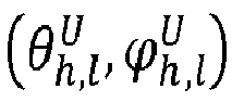
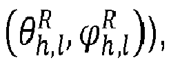
  • the AoA ⁇ h , l U ⁇ h , l U and the AoD ⁇ h , l R ⁇ h , l R can be determined by an exhaustive beam searching algorithm.
  • possible angles are tested to find one optimal AoA and AoD.
  • such approach may require a large amount of time due to its complexity.
  • a two-stage beam training method including a primary and an auxiliary beam search as described in detail in W. Wu, D. Liu, Z. Li, X. Hou, and M. Liu, "Two-stage 3D codebook design and beam training for millimeter-wave massive MIMO systems," in 2017 IEEE 85th Vehicular Technology Conference (VTC Spring), Sydney, NSW, Australia. IEEE, 2017, pp. 1-7 , which is incorporated herein by reference.
  • the present invention is not limited to such beam training approach and that, in general any other approach may be used, including the above-mentioned exhaustive search or its modifications.
  • Fig. 2 illustrates the hierarchical beam searching algorithm procedures for channel estimation.
  • the primary codebook generates a basic directional beam. The number of phase shifts of the primary codebook may be quite limited in order to reduce the complexity.
  • the small-size auxiliary codebook provides finer beams that are centered on each primary beam.
  • the term codebook refers to predefined beams set in the absence of channel state information.
  • the primary search uses hierarchical search to reduce the search time.
  • a two-way (binary) tree search is used here, at each layer.
  • w n l denote the codeword of the n th beam vector at the l th layer.
  • the codeword w n l is a scalar referring to a beam vector ( w i l , i being RIS side "r” or UE side "u" and I being the layer).
  • Beam vector specifies the antenna factors to form the beam.
  • At each layer l only 2 l antennas are activated (in each direction, transmitting direction as shown in the top part of Fig. 2 and receiving direction as shown in bottom part of Fig. 2 ).
  • Each parent codeword w n l has two child codewords w n l + 1 and w n + 1 l + 1 . It is aimed to obtain the AoA angles ⁇ h , l U ⁇ h , l U and the AoD angles ⁇ h , l R ⁇ h , l R through multiple steps corresponding to the primary beam search including V layers and the auxiliary beam search including V' layers. As shown in Fig.
  • the two beams are obtained by screening all possible beam patterns of the current, l -th, layer to select two beams having greatest similarity to the best beam of the preceding, ( l -1)-th, layer.
  • the similarity may be measured by any similarity measure (metric), e.g. as shown in W. Wu et al. above, e.g. by comparing the array factors of the beams.
  • metric any similarity measure (metric)
  • the present disclosure is not limited to comparing the array factor or to any particular similarity measure.
  • n Zx 1 complex Gaussian noise vector with zero-mean and variance ⁇ 0 2 .
  • the optimum (best) pair w ⁇ r V w ⁇ u V of beam vectors is obtained in the receiving, primary stage.
  • the primary codebook may be selected in various different ways and the present disclosure is not limited to any particular approach.
  • the primary codebook matrix in azimuth of K beam patterns, ⁇ - is the number of possible shifts. i.e., the discrete shift is 2pi/ ⁇
  • Parameter K may depend on the design (characteristics) of the antennas.
  • This codebook may be designed such that it has ⁇ possible states (i.e. ⁇ possible beams), and it fully spans the azimuth range.
  • the designing is achieved by selecting the desired values for N, K, and ⁇ .
  • the transmitting stage starts after acquiring the primary codebook, where an auxiliary beam search is performed by rotating the primary beam to create higher-resolution auxiliary beams.
  • a predefined number (such as one, two or more) of auxiliary beam patterns are uniformly and symmetrically distributed on the two sides of the known optimal primary beam. These beams define the auxiliary codebook.
  • a pair of beam vectors ( w ⁇ r , w ⁇ u ) is considered the optimum pair among the pairs based on the auxiliary codebook, when it fulfils Eq#9 above.
  • 9 beam pairs including the optimal primary beam and the two adjacent beams at both sides RIS (transmitting, Tx) and US (receiving, Rx) are evaluated to find the beam pair with the maximum received SNR.
  • This beam may selected and the search may further continue by selecting the beam direction with higher SNR potential and performing the beam scanning to find some pair with maximum SNR.
  • the beam search may be stopped if the SNR begins to decrease.
  • variations of the auxiliary search are possible. The above described approach is to merely illustrate one possibility. In general, as shown in Fig. 2 , the auxiliary search may be performed in V' layers.
  • both AoA and AoD can be obtained.
  • the AoA and AoD correspond to direction of the best receiver (UE) and transmitter (RIS) beams found in the beamforming training.
  • the AoD of the signals at the configurable surface is equal to the AoA at the receiving device.
  • the AoD of the signals at the configurable surface may be estimated from or based on the AoA at the receiving device.
  • This may be based on some prior knowledge or estimation of geometry (such as mutual position) of the RIS and the UE.
  • the modified channel matrix ⁇ is determined by an iterative reweighting algorithm. It is noted that the present disclosure is not limited to the iterative reweighting algorithm. The separation of the two matrices for the BS-RIS channel and the RIS-UE channel makes it possible to employ any other estimation / determination algorithm for the determination of the matrix ⁇ .
  • the channel estimation may be used at the UE for channel equalization.
  • he UE may report the channel estimation or some estimated channel parameters to the base station and the base station may take an appropriate action.
  • the base station may configure its own transmission characteristics accordingly, such as the departure angle, and/or transmission power, and/or beamforming pattern.
  • the trained reflection coefficients are configured by the transmitting device. It is noted that the estimated channel characteristics may be used to determine a new set of reflection coefficients for the RIS and to configure the RIS accordingly.
  • the configuration of the RIS may be performed by the BS (transmitting device) in accordance with a channel estimation reported from the UE. However, it is possible to configure the RIS by the UE. Or, as mentioned above, in general, the present disclosure is applicable to communication between any devices such as direct communication between two devices in which there is no hierarchy such as AP-STA or gNB-UE involved. Thus, in principle receiving device or transmission device or both may be allowed to configure the RIS based on the channel estimation by re-setting the reflection coefficients of the RIS.
  • the beamforming search comprises a hierarchic beamforming search including a first stage in which the beamforming search is performed in a plurality, V, of layers, wherein for each current layer following the first layer of the plurality of layer: (1) a predefined number of beams is searched to find the best beam in the current layer, wherein beams of the predefined number of beans searched are selected based on the best beam of the layer immediately preceding the current layer; and (2) in the current layer the number of antennas contributing to the beamforming is increased compared to the layer immediately preceding the current layer.
  • the search may end with the primary search and the best beam found therein may be taken to estimate the AoA and AoD, the channel and/or reflection coefficients.
  • some further search may be performed based on the best beam found in the primary search.
  • the present disclosure is not limited to any particular further beam search.
  • the hierarchic beamforming search further includes a second stage in which a plurality of beams in the vicinity of the beam found after the first stage are searched.
  • This secondary search may search a predetermined number b of beams in the vicinity of the best beam.
  • Such search may be performed iteratively, more than one time, i.e. in V' layers. For example, in each layer of such secondary search, the best beam from the previous layer is taken and b beams in the vicinity of the best beam are searched. This may be performed a predefined and fixed number of times (e.g. V ) and/or the search may terminate if the received quality (e.g. SNR or SINR or other channel quality measure) degrades.
  • the received quality e.g. SNR or SINR or other channel quality measure
  • the ideal reflection coefficients of the configurable surface 120 may be estimated, based on the trained reflection coefficients of the configurable surface 120 and the obtained AoA at the receiving device 135.
  • the term “ideal reflection coefficients” refers to reflection coefficients of the configurable surface in case of an ideal channel BS-RIS.
  • the term “ideal channel” here refers to a channel with a unitary gain (e.g., all coefficients of the corresponding channel matrix have an absolute value of one).
  • ⁇ x sin ⁇ t cos ⁇ t + sin ⁇ des cos ⁇ des
  • ⁇ y sin ⁇ t sin ⁇ t + sin ⁇ des sin ⁇ des
  • ⁇ x (.) and ⁇ y (.) can be viewed as steering vectors on the azimuth and the elevation direction, respectively
  • indices x and y denote location of the RIS elements (within the plane of the planar RIS).
  • ( ⁇ des , ⁇ des ) are respectively elevation and azimuth destination angles (herein corresponding to ⁇ h , l R ⁇ h , l R )
  • ( ⁇ t , ⁇ t ) are respectively elevation and azimuth angles incident on the RIS (herein corresponding to ⁇ g , l R ⁇ g , l R ) .
  • j is the imaginary unit
  • the wavelength of the signal
  • dx is a separation between elements of the configurable surface in an x-direction (e.g. vertical)
  • dy e.g., horizontal
  • the y-direction and the x-direction may be perpendicular with respect to each other.
  • the ideal reflection coefficients may be estimated based on an AoA at the configurable surface.
  • ⁇ AoA R is an elevation AoA at the configurable surface
  • ⁇ AoA R is an azimuth AoA at the configurable surface
  • ⁇ AoD R is an elevation AoD at the configurable surface
  • ⁇ AoD R is an azimuth AoD at the configurable surface
  • these may be obtained by the beamforming training.
  • ⁇ AoA R and/or ⁇ AoA R may be obtained by approximation and/or taking into account previous knowledge about mutual position of the BS and RIS.
  • the location of the BS may be fixed and known to the BS.
  • the location of the RIS may be known to the BS.
  • the BS may control and have knowledge of both the orientation of the own UPA and the UPA of the RIS. Consequently, based on the geometry of the BS and RIS (approximated, measured or known), the AoAs at the RIS ⁇ AoA R ⁇ AoA R as well as the AoDs from the base station ⁇ AoD R ⁇ AoD R may be obtained.
  • the AoA may be considered to be 0 (at least the elevation). However, such assumption is not necessary, and any other geometry may be considered.
  • the characteristics of the channel BS-RIS between the transmitting device 110 and the configurable surface 120 may be the method, according to a relation between (or a relation involving) the trained reflection coefficients and the estimated reflection coefficients.
  • the angels ⁇ AoA R , ⁇ AoA R , ⁇ AoD B , and ⁇ B AoD may be known from the geometry of the deployment of the RIS and the base station. In particular, said angles may be obtained based on the position of the base station, the position of the RIS, the orientation of the UPA of the base station, and/or the orientation of the UPA of the RIS.
  • ⁇ V' is the last configured set of phases by the BS at the V'-th stage of beam searching process
  • the angle ⁇ g , l R , ⁇ g , l R is the AoA at the RIS denoted as ⁇ AoA R , ⁇ AoA R above in the elevation and azimuth directions.
  • the angle may be different for different paths, in case there are multiple paths between the BS and the RIS.
  • ⁇ h , l R , ⁇ h , l R is an AoD at the RIS and is denoted as ⁇ AoD R , ⁇ AoD R above.
  • the AoD may be also different for different paths, in case there are multiple paths between the RIS and the UE.
  • the estimated characteristics of the non-ideal channel are a modified channel matrix ⁇ obtained in accordance with the relation (Eq#18), wherein:
  • the effect of ⁇ is known and its effects may be cancelled at the RIS.
  • the BS may control the RIS reflection coefficients to compensate for the estimated channel ⁇ .
  • the phase modification of the channel between the BS and the RIS may be compensated for by adapting the reflection coefficients of the RIS.
  • the remaining impact of the channel between the RIS and the UE, as well as the power on the channel between the BS and the RIS may be compensated for by the UE in terms of estimating the modified channel matrix.
  • the UE in general, the receiving device
  • the BS in general, the transmitting device
  • some information regarding the channel estimation may be, for instance, the best beam found, and/or the best AoA at the UE found in beam search, and/or the estimated refection coefficients or the like.
  • the BS in general, the transmitting device
  • the BS may be configured to receive the information and to configure the reflection coefficients of the configurable surface accordingly.
  • channel estimation model given in C. Hu, L. Dai, T. Mir, Z. Gao, and J. Fang, "Super-resolution channel estimation for mmwave massive MIMO with hybrid precoding," IEEE Transactions on Vehicular Technology, vol. 67, no. 9, pp. 8954-8958, 2018 (incorporated herein by reference) is adopted here to estimate path gains of all paths. It is noted that this estimation is only exemplary and that other approaches may be applied to estimate the RIS-UE channel with the knowledge of the estimated phases of the BS-RIS channel.
  • x ⁇ G ⁇ Fs ⁇ C M RIS ⁇ 1
  • each element x i is the i-th transmitted symbol.
  • known symbols at known indices are transmitted.
  • Y [ y 1 , y 2, ..
  • the estimation of the channel ⁇ becomes equivalent to the estimation of z , ⁇ U and ⁇ R , and the problem is formulated as: min z , ⁇ U , ⁇ R P 1 z ⁇ U ⁇ R ⁇ ⁇ z ⁇ ⁇ 0 , s . t . Y ⁇ Q H H ⁇ X F ⁇ ⁇
  • ⁇ ⁇ ⁇ 0 represents the number of non-zero elements i.e., the sparsest solution of the sparse channel H ⁇
  • H ⁇ is the estimated channel matrix for ⁇
  • is the estimation error tolerance.
  • ⁇ . ⁇ F denotes Frobenius norm.
  • min ⁇ r i ⁇ max ,
  • Channel tracking is typically much faster than the complete channel estimation. They make use of the results from the preceding channel estimation.
  • tracking may be performed by employing an EKF or LMS tracking algorithms as they may provide for low complexity and good performance.
  • the tracking algorithm starts with setting a pair of transmit and receive beams according to the estimated azimuth and elevation AoA/AoD from the channel estimator. While tracking, the predicted channel parameters should stay close to the actual values, so that the UE 135 stays within half of the beam width. Otherwise, if the tracking is no longer reliable or the path of the beams does not exist anymore, the channel parameters may be re-estimated. In particular, a discrete-time model for the received signal symbol period at the UE side is given in (Eq#21).
  • LMS or EKF algorithms may be used to track these parameters.
  • a method for tracking a location of a receiving device comprising: the method according to any of embodiments and examples mentioned above for estimating, at the receiving device 135, the characteristics of the channel (BS-UE) between the transmitting device 110 and the receiving device 135, and tracking, based on the estimated characteristics of the channel (BS-UE) between the transmitting device 110 and the receiving device 135 and/or the modified channel matrix ⁇ , the location of the communication device.
  • Fig. 4 summarizes an exemplary embodiment which makes use of the above-described separate estimation of the channel between the BS and RIS and between the RIS and UE.
  • the scheme can estimate both BS-RIS and RIS-UE channels separately, even though all RIS elements are passive.
  • the RIS-UE channel H is estimated by adopting the iterative reweight algorithm to estimate the channel path coefficients only, exploiting the resultant angles from the beam searching algorithm.
  • the proposed scheme enables RIS-assisted communication to track mobile user.
  • the parameters of channel H are tracked, e.g., using well-known algorithms such as extended Kalman filter (EKF) and least mean square (LMS) algorithms.
  • EKF extended Kalman filter
  • LMS least mean square
  • Fig. 4 shows an exemplary flow chart illustrating the method of the three-stage RIS channel estimation framework.
  • Stage one is estimation of the BS-RIS channel G. It starts with finding AoA/AoD between the RIS and the UE.
  • This stage includes the primary beam search (with layers 1 to V) and the auxiliary beam search (with layers 1 to V' ) .
  • the beam search is initiated by layer 1 of the primary search, and continues 420 over V layers of the primary search and the V' layers of the secondary search until secondary search is finished 430.
  • FIG. 5 illustrating primary beam patterns for ideal channel G and in azimuth domain (left) and elevation domain (right) when G is a geometric model with 5 paths.
  • the outputs of this beam searching are ⁇ V' , and ⁇ h , l R , ⁇ h , l R . Based on these outputs, the modified channel matrix ⁇ , which is a characteristics of the channel between the BS and the RIS, is estimated 440 as shown in Eq#18.
  • the second stage is estimation 460 of the modified channel matrix ⁇ between the RIS and the UE.
  • Input to this stage are received signal Y, pilot signal X, combining matrix W, ⁇ U , ⁇ R , pruning threshold z th , and termination threshold ⁇ .
  • the output of this stage are path gains of all paths.
  • the exemplary algorithm is sketched below as a high-level pseudo-code, based on the detailed embodiment described above, e.g. with reference to Eq#32 and Eq#33:
  • the third stage of the framework is tracking 470 the channel parameters of the channel H.
  • Input to the channel tracking 470 are the z opt , ⁇ , and ⁇ . These parameters are updated by using, e.g. the EKF algorithm.
  • the observation signal is tracked using Eq#34.
  • the updating and tracking are repeated until there is too much mobility 480, in which case the estimation 410-460 is repeated.
  • mobility may include UE movement, as well as larger changes of the channel contributed by other factors.
  • step 450 of setting the phases of the RIS may be performed but does not have to be performed. It may be performed at any stage, e.g. after the estimation or anytime.
  • the updating or setting the reflection coefficient may be performed according to the following method.
  • the method for setting reflection coefficients of a configurable surface may comprise performing beamforming search for transmission of signals over a channel (BS-UE) between the transmitting device and a receiving device, the channel including reflection on the configurable surface, thereby obtaining the trained reflection coefficients of the configurable surface, and an angle of arrival, AoA, of the signals at the receiving device.
  • BS-UE channel including reflection on the configurable surface
  • estimating G will cancel all the channel effect between the BS and RIS so that the reflected beam direction is easily controlled by changing the phases of RIS.
  • estimating H accurately recovering the information sent from the BS to the UE may be possible.
  • the estimated H or Heff may be used for channel equalization.
  • a receiving device 600_Rx which may include an apparatus for channel estimation for estimating, at a receiving device, characteristics of a channel (BS-UE) between a transmitting device and the receiving device, the channel including reflection on a configurable surface 650.
  • the channel estimation apparatus may comprise processing circuitry 690 configured to control a transceiver 670-680 of the receiving the device to perform beamforming search for transmission of signals over the channel (BS-UE), thereby obtaining: trained reflection coefficients of the configurable surface 650, and an angle of arrival, AoA, of the signals at the receiving device 600_Rx.
  • the processing circuitry may further estimate, based on the configurable surface and the obtained AoA at the receiving device 600_Rx, reflection coefficients of the configurable surface for an ideal channel (BS-RIS) between the transmitting device and the configurable surface. Moreover, processing circuitry may further estimate, according to a relation between the trained reflection coefficients and the estimated reflection coefficients, characteristics of a channel (BS-RIS) between the transmitting device 600_Tx and the configurable surface.
  • BS-RIS ideal channel
  • the processing circuitry 690 implements functions of baseband signal processing.
  • the processing circuitry may be a combination of one or more pieces of software and/or hardware. Methods described in the above exemplary embodiments and implementations may be implemented by this baseband signal processing portion.
  • the receiving device 600_Rx may comprise a transceiver which may further comprise an analog radio frequency (RF) combiner Q 670 and one or more RF chains 680.
  • the combiner 670 provides the received analog signal to the one or more RF chains.
  • RF radio frequency
  • the receiving device 600_Rx may include further parts as is known to those skilled in the art, such as parts performing coding and modulation and the like.
  • Fig. 6 shows a transmitting device 600_Tx is provided which may be capable of setting reflection coefficients of a configurable surface 650.
  • Such transmitting device 600_Tx may comprise processing circuitry 610.
  • the processing circuitry may perform functions of baseband digital processing.
  • the baseband processing may comprise (the processing circuitry 610 may be configured for) performing beamforming search for transmission of signals over a channel (BS-UE) between the transmitting device 600_Tx and a receiving device 600_Rx, the channel including reflection on the configurable surface, thereby obtaining: trained reflection coefficients of the configurable surface, and an angle of arrival, AoA, of the signals at the receiving device.
  • BS-UE channel between the transmitting device 600_Tx and a receiving device 600_Rx
  • the processing circuitry may further implement estimating an angle of departure, AoD, of the signals at the configurable surface from the AoA at the receiving device; estimating, based on the configurable surface and the obtained AoA at the receiving device, reflection coefficients of the configurable surface for an ideal channel (BS-RIS) between the transmitting device and the configurable surface; and estimating, according to a relation between the trained reflection coefficients and the estimated reflection coefficients, characteristics of a channel (BS-RIS) between the transmitting device and the configurable surface.
  • AoD angle of departure
  • the transmitting device 600_Tx may further comprise a transceiver.
  • the transceiver may include one or more RF chains 620 and analog beamforming module 630 which receives the signal from the RF chains 620 and generates the analog beamformed signal which is then transmitted from the UPA of the transmitting device 600_Tx towards the configurable surface 650 for the receiving device 600_Rx.
  • each BS and UE may implement both a receiving device and a transmitting device described above.
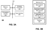
  • FIG. 3A An exemplary hardware structure of a transmitting and/or receiving device is shown in Fig. 3A.
  • Fig. 3A illustrates a device 350 according to some exemplary embodiments.
  • the device 350 comprises memory 310, processing circuitry 320, and a wireless transceiver 330, which may be capable of communicating with each other via a bus 301.
  • the device 350 may further include a user interface 340.
  • the user interface 340 is not necessary (for instance some devices for machine-to-machine communications or the like).
  • the device 350 may be, for instance a wireless module such as 5G or Wi-Fi or the like being a part of a computer such as laptop or tablet, it may be part of a mobile phone, smartphone or other portable / personal device, or the like.
  • the memory 310 may store a plurality of firmware or software modules, which implement some embodiments of the present disclosure.
  • the memory may 310 be read from by the processing circuitry 320.
  • the processing circuitry may be configured to carry out the firmware/software implementing the embodiments.
  • the processing circuitry 320 may include one or more processors, which in operation perform the steps of any of the above describe methods. This corresponds to the transmitting device (apparatus) including the corresponding functional modules (units).
  • Fig. 3B shows a schematic functional block diagram of the memory 310 and the functional code parts stored therein.
  • the functional code parts when executed on the processor(s) 320, perform the respective functions as follows.
  • Application code 360 implements the beam search (for example the primary and the secondary beam search).
  • Application code 370 implements an estimation of the channel between the BS and the RIS.
  • Application code 380 implements an estimation of the channel between the RIS and the UE.
  • Application code 390 may implement channel tracking.
  • any processing circuitry may be used, which may include one or more processors.
  • the hardware may include one or more of application specific integrated circuits (ASICs), digital signal processors (DSPs), digital signal processing devices (DSPDs), programmable logic devices (PLDs), field programmable gate arrays (FPGAs), processors, controllers, any electronic devices, or other electronic circuitry units or elements designed to perform the functions described above.
  • ASICs application specific integrated circuits
  • DSPs digital signal processors
  • DSPDs digital signal processing devices
  • PLDs programmable logic devices
  • FPGAs field programmable gate arrays
  • processors controllers, any electronic devices, or other electronic circuitry units or elements designed to perform the functions described above.
  • the functions performed by the transmitting apparatus may be stored as one or more instructions or code on a non-transitory computer readable storage medium such as the memory 310 or any other type of storage.
  • the computer-readable media includes physical computer storage media, which may be any available medium that can be accessed by the computer, or, in general by the processing circuitry 320.
  • Such computer-readable media may comprise RAM, ROM, EEPROM, optical disk storage, magnetic disk storage, semiconductor storage, or other storage devices.
  • Some particular and non-limiting examples include compact disc (CD), CD-ROM, laser disc, optical disc, digital versatile disc (DVD), Blu-ray (BD) disc or the like. Combinations of different storage media are also possible - in other words, distributed and heterogeneous storage may be employed.
  • a method for estimating, at a receiving device (135), characteristics of a channel is provided.
  • the channel is between a transmitting device (110) and the receiving device (135) and includes reflection on a configurable surface (120).
  • the method comprising performing beamforming search for transmission of signals over the channel (BS-UE), thereby obtaining i) trained reflection coefficients of the configurable surface (120), and ii) an angle of arrival (AoA) of the signals at the receiving device (135).
  • the method comprises estimating, based on the trained reflection coefficients of the configurable surface (120) and the obtained AoA at the receiving device (135), estimated reflection coefficients of the configurable surface (120) for an ideal channel (BS-RIS) between the transmitting device (110) and the configurable surface (120). Moreover, the method comprises estimating, according to a relation between the trained reflection coefficients and the estimated reflection coefficients, characteristics of a channel (BS-RIS) between the transmitting device (110) and the configurable surface (120).
  • BS-RIS ideal channel
  • estimating the estimated reflection coefficients comprises a step of estimating, from the AoA at the receiving device (135), an angle of departure (AoD) of the signals at the configurable surface. Furthermore, according to the second aspect, estimating the estimated reflection coefficients is based on the estimated AoD at the configurable surface.
  • the modified channel matrix ⁇ corresponds to a matrix obtained from a channel matrix G of the channel between the transmitting device (110) and the configurable surface (120) by setting an absolute value of each element of the channel matrix G to one. Furthermore, according to the fifth aspect, the method comprises a step of determining, based on the modified channel matrix ⁇ , a modified channel matrix ⁇ .
  • the modified channel matrix ⁇ is determined by an iterative reweighting algorithm.
  • the trained reflection coefficients are configured by the transmitting device.
  • the beamforming search comprises a hierarchic beamforming search including a first stage in which the beamforming search is performed in a plurality, V, of layers.
  • a predefined number of beams is searched to find a best beam in the current layer, wherein beams of the predefined number of beams searched are selected based on a best beam of a layer immediately preceding the current layer; and ii) in the current layer a number of antennas contributing to the beamforming is increased compared to the layer immediately preceding the current layer.
  • the hierarchic beamforming search further includes a second stage in which a plurality of beams in a vicinity of the beam found after the first stage are searched.
  • a method for tracking a location of a receiving device comprising the method according to any of the first to ninth aspect, for estimating, at the receiving device (135), the characteristics of the channel (BS-UE) between the transmitting device (110) and the receiving device (135). Furthermore, the method according to the tenth aspect comprises, tracking, based on the characteristics of the channel (BS-UE) between the transmitting device (110) and the receiving device (135) and/or the modified channel matrix ⁇ , the location of the communication device.
  • the method according to the tenth aspect is provided for tracking the location of the receiving device using extended Kalman filtering or least mean square, LMS, based tracking.
  • a computer program product comprises a non-transitory computer-readable medium comprising code instructions which, when executed on one or more processors, cause the one or more processors to perform the method according to any of the first to the eleventh aspect.
  • an apparatus for estimating, at a receiving device (135), characteristics of a channel is provided.
  • the channel is between a transmitting device (110) and the receiving device (135) and includes reflection on a configurable surface (120).
  • the apparatus comprises processing circuitry.
  • the processing circuitry is configured to control a transceiver of the receiving the device (135) to perform beamforming search for transmission of signals over the channel (BS-UE), thereby obtaining i) trained reflection coefficients of the configurable surface (120), and ii) an angle of arrival, AoA, of the signals at the receiving device (135).
  • the processing circuitry is configured to estimate, based on the configurable surface (120) and the obtained AoA at the receiving device (135), estimated reflection coefficients of the configurable surface (120) for an ideal channel (BS-RIS) between the transmitting device (110) and the configurable surface (120). Moreover, the processing circuitry is configured to estimate, according to a relation between the trained reflection coefficients and the estimated reflection coefficients, characteristics of a channel (BS-RIS) between the transmitting device (110) and the configurable surface (120).
  • BS-RIS ideal channel
  • a communication device comprises the apparatus for channel estimation according to the thirteenth aspect; and the transceiver.
  • a method for setting, by a transmitting device (110), reflection coefficients of a configurable surface (120) comprises performing beamforming search for transmission of signals over a channel (BS-UE) between the transmitting device (110) and a receiving device (135), wherein the channel includes reflection on the configurable surface (120).
  • BS-UE channel
  • the method comprises estimating an angle of departure (AoD) of the signals at the configurable surface from the AoA at the receiving device (135).
  • a computer program is provided, stored on a non-transitory medium, and comprising code instructions which when executed by a computer or by a processing circuitry, performs steps of any of the above mentioned methods.
  • the processing circuitry and/or the transceiver is embedded in an integrated circuit, IC.

Landscapes

  • Engineering & Computer Science (AREA)
  • Computer Networks & Wireless Communication (AREA)
  • Signal Processing (AREA)
  • Power Engineering (AREA)
  • Physics & Mathematics (AREA)
  • Mathematical Physics (AREA)
  • Radio Transmission System (AREA)
  • Mobile Radio Communication Systems (AREA)

Abstract

The present disclosure relates to channel estimation, at a receiving device of a communication system employing a (re)configurable surface. The channel estimation includes beamforming search to obtain trained reflection coefficients of the configurable surface and an angle of arrival, AoA, of the signals at the receiving device. Then, based on the configurable surface and the obtained AoA at the receiving device, reflection coefficients of the configurable surface are derived for an ideal channel portion between the transmitting device and the configurable surface. According to a relation between the trained reflection coefficients and the estimated reflection coefficients, the estimation of the characteristics of a channel between the transmitting device and the configurable surface is performed. The channel estimation may be employed in user mobility tracking.

Description

  • The present disclosure relates to channel estimation at communication devices, which communicate with other communication devices by reflection on a configurable surface.
  • BACKGROUND
  • Millimeter-wave (mmWave) communication has become one of the key technologies of 5G communication systems. Although mmWave may achieve high data rates and high spectrum efficiency due to its wider signal bandwidth, it usually suffers from severe path-loss and blockage of the line of sight between the communicating devices.
  • Reconfigurable intelligent surface (RIS) has been discussed as a technology to improve the wireless communication performance. The elements of RIS can reflect, refract, absorb, or focus the incoming waves toward any desired direction. This functionality may help to overcome the above-mentioned issues with mmWave propagation condition including path attenuation and blockage.
  • However, channel estimation in RIS-aided communication is still a major concern due to the passive nature of RIS elements, and estimation overhead that arises with multiple-input multiple-output (MIMO) system.
  • SUMMARY
  • Methods and techniques are described for estimating channel in communication system including receiving and transmitting device, communicating with each other via a configurable surface.
  • The invention is specified by the scope of the independent claims. Some further exemplary embodiments are subject matter of the dependent claims
  • According to an embodiment, a method is provided for estimating, at a receiving device, characteristics of a channel (BS-UE) between a transmitting device and the receiving device, the channel including reflection on a configurable surface, the method comprising: performing beamforming search for transmission of signals over the channel (BS-UE), thereby obtaining: trained reflection coefficients of the configurable surface, and an angle of arrival, AoA, of the signals at the receiving device; estimating, based on the trained reflection coefficients of the configurable surface and the obtained AoA at the receiving device, estimated reflection coefficients of the configurable surface for an ideal channel (BS-RIS) between the transmitting device and the configurable surface; and estimating, according to a relation between the trained reflection coefficients and the estimated reflection coefficients, characteristics of a channel (BS-RIS) between the transmitting device and the configurable surface.
  • These and other features and characteristics of the presently disclosed subject matter, as well as the methods of operation and functions of the related elements of structures and the combination of parts and economies of manufacture, will become more apparent upon consideration of the following description and the appended claims with reference to the accompanying drawings, all of which form a part of this specification. It is to be expressly understood, however, that the drawings are for the purpose of illustration and description only and are not intended as a definition of the limits of the disclosed subject matter. As used in the specification and the claims, the singular form of "a," "an," and "the" include plural referents unless the context clearly dictates otherwise.
  • BRIEF DESCRIPTION OF DRAWINGS
  • An understanding of the nature and advantages of various embodiments may be realized by reference to the following figures.
  • FIG. 1
    is a schematic drawing of a system for implementing some embodiments of the disclosure.
    FIG. 2
    is a schematic drawing illustrating a hierarchical beam searching algorithm procedures for channel estimation.
    FIG. 3
    is a block diagram illustrating an exemplary implementation of an apparatus for channel estimation.
    FIG. 4
    is a flow diagram illustrating a method for channel estimation and tracking.
    FIG. 5
    is a schematic drawing illustrating primary beam patterns for ideal channel G and in azimuth domain (left) and elevation domain (right) when G is a geometric model with 5 paths.
    FIG. 6
    is a schematic drawing illustrating communication devices at the receiver and the transmitter side of a channel including RIS.
  • Like reference numbers and symbols in the various figures indicate like elements, in accordance with certain example implementations.
  • DESCRIPTION
  • For purposes of the description hereinafter, the terms "end," "upper," "lower," "right," "left," "vertical," "horizontal," "top," "bottom," "lateral," "longitudinal," and derivatives thereof shall relate to the disclosed subject matter as it is oriented in the drawing figures. However, it is to be understood that the disclosed subject matter may assume various alternative variations and step sequences, except where expressly specified to the contrary. It is also to be understood that the specific devices and processes illustrated in the attached drawings, and described in the following specification, are simply exemplary embodiments or aspects of the disclosed subject matter. Hence, specific dimensions and other physical characteristics related to the embodiments or aspects disclosed herein are not to be considered as limiting unless otherwise indicated.
  • No aspect, component, element, structure, act, step, function, instruction, and/or the like used herein should be construed as critical or essential unless explicitly described as such. Also, as used herein, the articles "a" and "an" are intended to include one or more items and may be used interchangeably with "one or more" and "at least one." Furthermore, as used herein, the term "set" is intended to include one or more items (e.g., related items, unrelated items, a combination of related and unrelated items, and/or the like) and may be used interchangeably with "one or more" or "at least one." Where only one item is intended, the term "one" or similar language is used. Also, as used herein, the terms "has," "have," "having," or the like are intended to be open-ended terms. Further, the phrase "based on" is intended to mean "based at least partially on" unless explicitly stated otherwise.
  • Reconfigurable intelligent surfaces (RISs) are also referred to as intelligent reconfigurable surfaces (IRSs). Herein, they are also referred to more simply as reconfigurable surfaces or configurable surfaces. In other words, a configurable surface is a surface including a plurality of elements with (re)configurable reflection characteristics.
  • In general, a RIS is a uniform planar array with a large number of reflective elements. Each reflective element is adapted to passively reflect incident signal and introduce a phase shift to it. In contrast to mirrors, RISs are able to adjust the angle of reflection and electric field strength. RIS technology may support MIMO systems in controlling and improving the wireless channel. The adjustable passive elements can individually steer the incident electro-magnetic (EM) wave toward any specific direction by changing their phases and gains only. Adjusting these elements may allow to align multipath of the reflected signal so that they are added constructively at the receiver. With a proper RIS size and reflection coefficients, the reflected signal is a beam, where the width of this beam is inversely proportional with the size of the RIS. The RIS elements passively reflect the signal, they are easy to implement, have low-cost deployment, and most importantly do not cause noise amplification.
  • On the other side, RIS also imposes challenges such as channel estimation. Since the RIS is built of a large number of passive elements, RIS-aided communication networks have faced difficulties in estimating the channel reliably. In order to overcome these difficulties, some channel estimation techniques have been proposed, mostly following some simplifying assumptions.
  • In mmWave, channel estimation becomes more critical and few concern these high bands. In some works, prior knowledge about the channel between a base station (BS) and the RIS. However, considering the channel BS-RIS to be known and time-invariant is not practical since mmWave channel is sensitive to any small changes, which may be caused by any scatterers between the BS and RIS. Moreover, some two-stage cascaded channel estimation protocol have been proposed by exploiting the sparsity of the mmWave MIMO channel between a single BS, RIS, and user equipment (UE). In the receiving stage, beam searching approach is introduced to have high angular domain information, then in a transmitting stage, adaptive grid matching pursuit algorithm is proposed to estimate the high-resolution cascaded channel.
  • Such channel estimation techniques depend on either cascaded channel concept or some limiting assumptions for estimating the channel BS-RIS-UE. Since RIS reflects the signal and focuses the energy into a specific direction, UE's location should be considered in the estimation process. The UE location may change in time, so that user tracking could be a desirable feature. Moreover, it has been shown that the pathloss is a function of reflection coefficients of RIS, which are typically ignored in the channel estimation process when the phases are optimized for channel estimation.
  • The present disclosure addresses channel estimation, beamforming, and user tracking in mmWave RIS-MIMO systems. By providing the relation of RIS design with MIMO system, a three-stage framework may then be employed which is exemplified in one of the embodiments. In particular, in one embodiment, the channel between the BS and the RIS is estimated using hierarchical beam searching. In addition, in a further embodiment, the channel between the RIS and user is estimated, e.g. using an iterative resolution algorithm. In a further embodiment, a tracking algorithm is employed to track channel parameters between the RIS and the user.
  • Reconfigurable (or configurable) Intelligent Surface (RIS) model
  • Fig. 1 illustrates an exemplary communication system 100, which may implement some embodiments of the present disclosure. In particular, the communication system 100 includes a base station (BS) 110, a RIS 120 and a user equipment (UE, also referred to as user or terminal) 135. This communication system is only exemplary. In general, a communication system for implementing the present invention may include a receiving device (mobile or stationary), a RIS, and a transmitting device (mobile or stationary).
  • The BS 110 in Fig. 1 is a base station such as an eNB or gNB of a 3GPP system such as long term evolution (LTE) or new radio (NR) or another generation system. In other words, the BS may be an access network node of a cellular wireless system. However, the BS may also be an access point (AP) of a local area network (LAN), such wireless LAN, e.g. according to IEEE 802.11 standards. The embodiments presented herein may be readily employed in systems such as 3GPP NR or IEEE 802.11be or other emerging systems. Another possibility is to employ the present disclosure to any communication between two devices in device to device communication, without presence of or connection to some network infrastructure.
  • The RIS 120 is a planar array of passive reflective element with configurable phase shift and possibly/optionally a configurable attenuation. Fig. 1 shows merely schematically a RIS of a square form with 3 x 3 elements, resulting in number of elements MRIS = 9. However, this is only a schematic representation. In practice, the RIS may have a much larger size. For example, sizes of MRIS = 16, 64, or 256 may be employed, or any other square sizes. The RIS does not have to be square. It may be rectangular or have any other shape. Several different shapes such as square, rectangular, hexagonal, circular, etc. have been studied.
  • The UE 135 in Fig. 1 is illustrated as a user device at time tk in specific location which could be a mobile moving toward different location UE 130 at time t k+1 . However, the present disclosure is not limited thereto and, in general, the UE 135 may be any communication device, such as machine-type device for Internet of Things (IoT) application a base station, an access point, a repeater, or any otherwireless infrastructure entity. In general, the RIS 120 may, at the same time, reflect beams directed to different receiving devices.
  • The channel between the BS 110 and the RIS 120 is denoted as G. The channel between the RIS 120 and a UE 135 is denoted as H. In particular, G and H refer to channel matrices, which describe the respective channel characteristics. A channel matrix specifies how the channel modifies an input signal. For example, an input signal x transmitted from multiple antennas (and thus being represented as a vector) is modified by the channel matrix G and added a noise signal n (also a vector), resulting in signal y = G·x + n (a vector of the size corresponding to the number of receiving antennas). In the present example, thus G C M RIS × M BS
    Figure imgb0001
    and H C M UE × M RIS
    Figure imgb0002
    denote the channels (represented by the channel matrices) between BS-RIS and RIS-UE, respectively. Symbols MBS and MUE denote the number of antennas (antenna array elements) at the BS 110 and the UE 135, respectively.
  • In the communication system 100, not only the RIS 120, but also the BS 110 and the UE 135, may be equipped with an equidistant uniform planar array (UPA) as an antenna structure with half-wavelength distance between the antenna elements. The uplink and downlink transmissions may use a time-division duplex (TDD) protocol that exploits channel reciprocity for the acquisition of channel state information (CSI) at the RIS 120 in both link directions (such as uplink and downlink, or in general both directions between the communicating entities). The BS 110 is typically assumed to have MRF radio frequency (RF) chains where the number of these chains is much smaller than the number antenna array elements and larger than the number, k, of UEs, 135, i.e. k ≤ MRF << MBS. UE 135 is considered to have one RF chain. The RIS 120 may be placed near to the UE side and far from the BS side to reduce (minimize) the path-loss effect. In order to fully exploit the functionality of the RIS 120, the channel path between the BS 110 and UE 135 is shown in Fig. 1 to be blocked by an obstacle 140. Thus, there is no line of sight (LoS) between the BS 110 and the UE 135. The distance between the BS and the RIS is denoted as dg, whereas the distance between the RIS and a UE is denoted as dh.
  • The RIS elements may be placed in a uniform rectangular shape. For example, assuming a square shape with dimensions NRIS x NRIS, the MRIS = NRIS 2 reflection coefficients of these elements may be represented by a following reflection coefficient matrix: ϕ = ϕ 1 , 1 ϕ 1 , N RIS ϕ N RIS , 1 ϕ N RIS , N RIS
    Figure imgb0003
    wherein φn,m = γn,men,m is reflection coefficient of the (n, m)-th RIS element, where αn,m ∈ [0,2π) represents the phase shift induced by the (n, m)-th element, and γn,m ∈ [0,1] stands for the reflection gain. Usually, it is a good approximation to assume that the reflection gain is unity: γn,m = 1, ∀ (n, m). The indices n and m address the vertical and horizontal (row and column) coordinates of the corresponding antenna element within the UPA of the RIS 120.
  • Another convenient representation of reflection coefficients in term of facilitating computations can be given as: Θ = diag vec ϕ
    Figure imgb0004
  • This corresponds to a diagonal matrix with the diagonal corresponding to vectorized matrix φ . The reflection coefficients φn,m of the RIS 120 are configurable and, in some embodiments, may be configured (set) by the BS 110.
  • Considering the system model shown in Fig. 1, the reflected signals from each element of the RIS 120 may be configured to be aligned in phase to enhance the received signal power. The free space pathloss can be calculated as shown in W. Tang, M. Z. Chen, X. Chen, J. Y. Dai, Y. Han, M. Di Renzo, Y. Zeng, S. Jin, Q. Cheng, and T. J. Cui, "Wireless communications with reconfigurable intelligent surface: Path loss modeling and experimental measurement," arXiv preprint arXiv:1911.05326, 2019 which is incorporated herein by reference.
  • The channel with a minimum pathloss may be seen as a channel description when assuming that a signal is going to be reflected toward the same location and G is an ideal channel i.e., it has a unitary gain. However, when G is assumed to be a sparse channel where LoS path between BS 110 and RIS 120 is the dominant path, it is observed that the beam is shifted toward a direction different from that of the location of the UE 135. A sparse channel has less number of scatters resulting in a small number of correlated multipath which leads to channel representation with few number of non-zero elements. On the other hand, when channel G is very rich on scattering, the UE 135 will receive a very low power from RIS 120 so that the RIS may react worse than a normal reflector (metallic surface, wall, etc...). Thus, for a successful reflection, G, may be individually estimated and then equalized at the RIS 120 by simply reversing its effect.
  • After reflecting the beam at the RIS 120, the UE 135 estimates and equalizes H to complete successful communication. In other words, the RIS 120 performs two different operations separately:
    1. 1) Accumulation, where it collects all the energy received by each of its elements (resulting in gain being proportional to M RIS 2
      Figure imgb0005
      ) and then aligning them by cancelling the effects of the channel G.
    2. 2) Beamforming/Steering, the RIS 120 acts like a virtual BS (in general, a virtual transmitter), and focuses or steers the incoming electromagnetic waves toward the UE's location.
  • As mentioned above, most of the known approaches consider the UE 135 to be stationary, and BS 110 to have always LoS with RIS 120. However, these assumptions are not realistic, and tend to limit the use of the RIS 120. They are a consequence of a cascaded channel model that is given by H cascaded = G·H. This representation makes channel tracking in time almost impossible, since any change in H cascaded could be due to change in G or H or both. Herein, since G but not H affects the phases of the RIS, G may be estimated separately, and estimating H becomes feasible which may enable tracking the UE 135.
  • BS-RIS channel and channel matrix G
  • In order to estimate channel, training (reference) symbols s are transmitted from the BS 110 to the UE 135. In particular, the training symbols s may be transmitted via orthogonal precoding beams for user 135, such that there is no inter-user interference to the other users in the system. Under this assumption, the analysis may be restricted to one representative UE 135 without loss of generality. Under the assumption of flat-fading and perfect timing and frequency synchronization, the sparsity of the channel is exploited by using geometric channel modeling. The model represented by the channel matrix G C M RIS × M BS
    Figure imgb0006
    may be given as G = l = 1 L g z g , l a M RIS θ g , l R φ g , l R a M BS H θ g , l B φ g , l B = A M RIS Ω R diag z g A M BS H Ω B ,
    Figure imgb0007
    where Lg is the number of channel paths received at the RIS 120 (i.e., paths between the BS 110 and the RIS 120), θ g , l R ,
    Figure imgb0008
    φ g , l R
    Figure imgb0009
    are respectively the elevation and azimuth angle of arrival (AoA) at the RIS of the l-th BS-RIS-path, θ g , l B ,
    Figure imgb0010
    φ g , l B
    Figure imgb0011
    are respectively the elevation and azimuth angle of departure (AoD) from the base station of the l-th BS-RIS-path, and zg,l is the complex channel coefficient between BS-RIS at an l-th path. Moreover, Ω R = θ g , 1 R φ g , 1 R , θ g , 2 R φ g , 2 R , , θ g , L g R φ g , L g R T ,
    Figure imgb0012
    Ω B = θ g , 1 B φ g , 1 B , θ g , 2 B φ g , 2 B , , θ g , L g B φ g , L g B ,
    Figure imgb0013
    zg = [z g,1,z g,2,...,zg,Lg ] T , diag( z g ) is the diagonal matrix C L g × L g
    Figure imgb0014
    having the individual elements zg,l of the vector zg on its diagonal, symbol a MRIS denotes the array response vector of the UPA of the RIS 120, and symbol a MBS denotes the array response vector of the UPA of the BS 110. As can be seen in the above notation, superscript B refers to base station 110 (in general to the transmitting device), R refers to the RIS 120, and U will refer to the UE 135 (in general to a receiving device).
  • In general, an array response vector of an UPA is represented by: a M i θ φ = 1 M i q sin θ cos φ p sin θ sin φ ,
    Figure imgb0015
    where q u = 1 , e j 2 π λ du , , e j 2 π λ N x 1 du T
    Figure imgb0016
    and p v = 1 , e j 2 π λ dv , , e j 2 π λ N y 1 dv T ,
    Figure imgb0017
    for i ∈ {RIS,BS}. Symbol ⊗ represents Kronecker product, λ is the wavelength of the signal, Nx and Ny denote respectively the number of elements of the UPA in the vertical and horizontal dimension, du and dv denote respectively the distance between neighboring elements of the UPA in the vertical and horizontal direction. Accordingly, A MRIS R ) and A M BS H Ω B
    Figure imgb0018
    are matrices given by: A M i Ω j = a M i θ g , 1 j φ g , 1 j , a M i θ g , 2 j φ g , 2 j , , a M i θ g , L g j φ g , L g j ,
    Figure imgb0019
    for i ∈ {RIS,BS} and j ∈ {R,B}.
  • It is noted that for sparse channels, the number of paths Lg is much lower than number of antenna elements at the RIS. For instance, for about 10 antenna elements, 1 or 2 paths could be considered.
  • RIS-UE channel and channel matrix H
  • Similarly, H C M UE × M RIS
    Figure imgb0020
    can be expressed as: H = l = 1 L h z h , l a M MU θ h , l R φ h , l R a M RIS H θ h , l B φ h , l B = A M UE Ψ U diag z h A M RIS H Ψ R
    Figure imgb0021
    where θ h , l B ,
    Figure imgb0022
    φ h , l B
    Figure imgb0023
    are respectively the elevation and azimuth AoA of the I-th RIS-UE-path, θ h , l R ,
    Figure imgb0024
    φ h , l R
    Figure imgb0025
    are respectively the elevation and azimuth AoD of the I-th RIS-UE-path. Moreover, Ψ U = θ h , 1 U φ h , 1 U θ h , 2 U φ h , 2 U ... θ h , L h U φ h , L h U T ,
    Figure imgb0026
    symbol a MBU denotes the array response vector of the UPA of the UE135, Lh is number of paths between the RIS 120 and the UE 135, Ψ R = θ h , 1 R φ h , 1 R , θ h , 2 R φ h , 2 R , , θ h , L h R φ h , L h R T ,
    Figure imgb0027
    zh = [z h,1,z h,2,...,zh,Lh ] T, and diag( zh ) is the diagonal matrix C L h × L h
    Figure imgb0028
    having the individual elements zh,l of the vector zh on its diagonal.
  • Accordingly, A MUE U ) and A M RIS H Ψ R
    Figure imgb0029
    are matrices given by A M i Ψ j = a M i θ h , 1 j φ h , 1 j , θ h , 2 j φ h , 2 j , , θ h , L h j φ h , L h j ,
    Figure imgb0030
    for i ∈ {UE,RIS} and j ∈ {U,R}.
  • BS-RIS-UE channel and channel matrix Heff
  • The overall channel H eff C M UE × M BS
    Figure imgb0031
    between the BS-RIS-UE is given by: H eff = β d g d h θ des φ des HΘG ,
    Figure imgb0032
    where β(dg,dhdesdes ) is a total pathloss calculated as in the paper by W. Tang et al mentioned above. That is, the pathloss is in general a function of the distance dg between the base station and the RIS, the distance dh between the RIS and the UE (see Fig. 1), and the departure angle of signals from the RIS.
  • Channel estimation framework
  • In order to estimate the channel, the effective channel in (Eq#6) can be rewritten in terms of modified channel matrices and as follows: H eff = β d g d h θ des φ des H ^ Θ G ^ ,
    Figure imgb0033
    where H ^ = A M UE Ψ U diag z A M RIS H Ψ R ,
    Figure imgb0034
    and G ^ = A M RIS Ω R diag e j . arg z g A M BS H Ω B .
    Figure imgb0035
    Here, diag e j . arg z g = e j . arg z g , 1 0 0 e j . arg z g , L g ,
    Figure imgb0036
    where arg(zg,l ) denotes the phase of the coefficient zg,l = |zg,l |e j.arg(z g,l ). Since G is directly responsible for altering the RIS phases, it may be more meaningful to represent it only in terms of ∠zg,l = arg(zg,l ), and include the channel gain | zg | into H. z is containing the channel coefficients zh,l of the channel H and the channel gain |zg,l | of the channel G .
  • In general, the modified channel matrix corresponds to a matrix obtained from a channel matrix G of the channel between the transmitting device (110) and the configurable surface (120) by setting an absolute value of each element of the channel matrix G to one, and further comprising a step of determining, based on the modified channel matrix , a modified channel matrix . In other words, the modified channel matrix only accounts for the phase change caused by the BS-RIS channel. The power change of G becomes part of the modified matrix .
  • Writing the channel in this form may allow for estimating H and G separately. The BS-RIS channel G can then be estimated using hierarchical beam searching algorithm. Furthermore, the RIS-UE channel H can be estimated, e.g. by adopting an iterative reweight algorithm to estimate channel path coefficients only, exploiting the angles resulting from the beam searching algorithm.
  • Estimation of BS-RIS channel
  • Since mmWave channel is sparse and the new representation of the BS-RIS has a unit amplitude (because the G channel coefficients are transferred to be included in channel H, channel G became with phases only and unit gains), the problem of estimating becomes equivalent to the estimation of (e jarg(z g ) of each path. In other words, causes a shift in the reflected beam, and hence, estimating this shift leads to estimating itself. This is performed in the following three steps, which will be described below in more detail:
    1. 1) Estimating AoA and AoD, θ h , l U φ h , l U
      Figure imgb0037
      and θ h , l R φ h , l R ,
      Figure imgb0038
      for the signal reflected by the RIS 120.
    2. 2) Obtaining the reflection coefficients of RIS in the absence of 's effect by substituting the angles θ h , l U φ h , l U
      Figure imgb0039
      and θ h , l R φ h , l R
      Figure imgb0040
      in equation (Eq#16) and then get the matrix Θ from equation (Eq#2).
    3. 3) Then, the so obtained reflection coefficients are compared to the last coefficient set by the BS and their phases are subtracted from each other to obtain Ĝ.
    Estimating angle of arrival (AoA) and angle of departure (AoD)
  • In general, by performing beamforming search (or beamforming training) for transmission of signals over the BS-UE channel, trained reflection coefficients of the configurable surface 120, and an angle of arrival (AoA) of the signals at the receiving device 135 may be obtained.
  • More specifically, the AoA θ h , l U φ h , l U
    Figure imgb0041
    and the AoD θ h , l R φ h , l R
    Figure imgb0042
    can be determined by an exhaustive beam searching algorithm. In the exhaustive beam searching algorithm, possible angles are tested to find one optimal AoA and AoD. However, such approach may require a large amount of time due to its complexity.
  • Accordingly, in the following, a two-stage beam training method is employed, including a primary and an auxiliary beam search as described in detail in W. Wu, D. Liu, Z. Li, X. Hou, and M. Liu, "Two-stage 3D codebook design and beam training for millimeter-wave massive MIMO systems," in 2017 IEEE 85th Vehicular Technology Conference (VTC Spring), Sydney, NSW, Australia. IEEE, 2017, pp. 1-7 , which is incorporated herein by reference. However, it is noted that the present invention is not limited to such beam training approach and that, in general any other approach may be used, including the above-mentioned exhaustive search or its modifications.
  • In the following, the hierarchic, two-stage beam training method is briefly summarized. For simplicity, the training procedure is described in azimuth only. Analogically, the procedure in elevation can be deduced. Fig. 2 illustrates the hierarchical beam searching algorithm procedures for channel estimation. The primary codebook generates a basic directional beam. The number of phase shifts of the primary codebook may be quite limited in order to reduce the complexity. The small-size auxiliary codebook provides finer beams that are centered on each primary beam. Here, the term codebook refers to predefined beams set in the absence of channel state information.
  • In an exemplary implementation, the primary search uses hierarchical search to reduce the search time. A two-way (binary) tree search is used here, at each layer. Let w n l
    Figure imgb0043
    denote the codeword of the nth beam vector at the lth layer. Accordingly, the codeword w n l
    Figure imgb0044
    is a scalar referring to a beam vector ( w i l ,
    Figure imgb0045
    i being RIS side "r" or UE side "u" and I being the layer). Beam vector specifies the antenna factors to form the beam. At each layer l only 2 l antennas are activated (in each direction, transmitting direction as shown in the top part of Fig. 2 and receiving direction as shown in bottom part of Fig. 2). In total, there will be ℵ possible beams and V = log2(ℵ). Each parent codeword w n l
    Figure imgb0046
    has two child codewords w n l + 1
    Figure imgb0047
    and w n + 1 l + 1 .
    Figure imgb0048
    It is aimed to obtain the AoA angles θ h , l U φ h , l U
    Figure imgb0049
    and the AoD angles θ h , l R φ h , l R
    Figure imgb0050
    through multiple steps corresponding to the primary beam search including V layers and the auxiliary beam search including V' layers. As shown in Fig. 2, layer 1 (i.e., the first layer) operation starts by testing four possible pairs of wide beams in four successive time slots, where the RIS 120 uses w r = w 1 1 w 2 1
    Figure imgb0051
    at the reflecting mode (determining AoD) and the UE 135 uses w u = w 1 1 w 2 1
    Figure imgb0052
    at the receiving mode (determining AoA). In layer 2, more antenna elements are employed to generate four narrower beams, two at the reflecting mode w r = w 1 2 w 2 2
    Figure imgb0053
    and two at the receiving mode w u = w 1 2 w 2 2
    Figure imgb0054
    etc. until the V-th layer which terminates the primary search. For example, the two beams (same applies for the reflecting and the receiving mode) are obtained by screening all possible beam patterns of the current, l-th, layer to select two beams having greatest similarity to the best beam of the preceding, (l-1)-th, layer. The similarity may be measured by any similarity measure (metric), e.g. as shown in W. Wu et al. above, e.g. by comparing the array factors of the beams. However, the present disclosure is not limited to comparing the array factor or to any particular similarity measure.
  • The resulted signal from the lth layer can be written as: y l = β d g d h θ des φ des w u l H H ^ w r l s ^ + w u l H n
    Figure imgb0055
    where = s, s = [s 1,s 2,...,sZ ] T is Zx1 vector of transmitted training symbols (known at the BS and the UE), and n is Zx1 complex Gaussian noise vector with zero-mean and variance σ 0 2 .
    Figure imgb0056
  • At each layer l we search for the pair w ˜ r l w ˜ u l
    Figure imgb0057
    of beam vectors that satisfies the highest received SNR as follows: max w r l , w u l w u l H H ^ w r l s ^ 2 = w ˜ u l H H ^ w ˜ r l s ^ 2
    Figure imgb0058
  • After V layers of primary beam search, the optimum (best) pair w ˜ r V w ˜ u V
    Figure imgb0059
    of beam vectors is obtained in the receiving, primary stage.
  • The primary codebook may be selected in various different ways and the present disclosure is not limited to any particular approach. By way of an example only, the primary codebook matrix in azimuth of K beam patterns, τ - is the number of possible shifts. i.e., the discrete shift is 2pi/τ, and NRIS elements are given as in the above mentioned paper by W. Wu et al. as follows: w n , k az = exp j 2 π τ nk τ K ,
    Figure imgb0060
    where n = 0,1...NRIS - 1 and k = 0,1...K - 1. Parameter K may depend on the design (characteristics) of the antennas. This codebook may be designed such that it has ℵ possible states (i.e. ℵ possible beams), and it fully spans the azimuth range. The designing is achieved by selecting the desired values for N, K, and τ. Similarly, the primary beam codebook matrix in elevation is given by: w n , k el = exp j 2 π τ nk τ 2 K 2 .
    Figure imgb0061
  • The transmitting stage starts after acquiring the primary codebook, where an auxiliary beam search is performed by rotating the primary beam to create higher-resolution auxiliary beams.
  • In particular, a predefined number (such as one, two or more) of auxiliary beam patterns are uniformly and symmetrically distributed on the two sides of the known optimal primary beam. These beams define the auxiliary codebook. Finally, a pair of beam vectors ( r , u ) is considered the optimum pair among the pairs based on the auxiliary codebook, when it fulfils Eq#9 above. As illustrated in Fig. 2, for example, 9 beam pairs including the optimal primary beam and the two adjacent beams at both sides RIS (transmitting, Tx) and US (receiving, Rx) are evaluated to find the beam pair with the maximum received SNR. This beam may selected and the search may further continue by selecting the beam direction with higher SNR potential and performing the beam scanning to find some pair with maximum SNR. The beam search may be stopped if the SNR begins to decrease. As is clear to those skilled in the art, variations of the auxiliary search are possible. The above described approach is to merely illustrate one possibility. In general, as shown in Fig. 2, the auxiliary search may be performed in V' layers.
  • Since the optimal transmission beam is represented by a weighting vector w = el az , both AoA and AoD can be obtained. Using Eq#4, Eq#10, and Eq#11, the AoA from the RIS 120 to the UE 135 can be found as: θ h , l U φ h , l U = sin 1 λ τ K , sin 1 λ τ 2 K 2 .
    Figure imgb0062
  • In other words, the AoA and AoD correspond to direction of the best receiver (UE) and transmitter (RIS) beams found in the beamforming training.
  • In the present model, the RIS 120 is considered to be located near to UE 135. Consequently, it may be assumed that the antenna array of the UE is always parallel to the RIS, hence θ h , l R φ h , l R =
    Figure imgb0063
    θ h , l U φ h , l U
    Figure imgb0064
    applies. In other words, it may be estimated that the AoD of the signals at the configurable surface is equal to the AoA at the receiving device. In general, the AoD of the signals at the configurable surface may be estimated from or based on the AoA at the receiving device.
  • This may be based on some prior knowledge or estimation of geometry (such as mutual position) of the RIS and the UE.
  • Once the modified matrix is estimated, according to some embodiments, the modified channel matrix is determined by an iterative reweighting algorithm. It is noted that the present disclosure is not limited to the iterative reweighting algorithm. The separation of the two matrices for the BS-RIS channel and the RIS-UE channel makes it possible to employ any other estimation / determination algorithm for the determination of the matrix Ĥ.
  • The result of the estimation may be used in many different ways. For example, the channel estimation may be used at the UE for channel equalization. Alternatively or in addition, he UE may report the channel estimation or some estimated channel parameters to the base station and the base station may take an appropriate action. For example, the base station may configure its own transmission characteristics accordingly, such as the departure angle, and/or transmission power, and/or beamforming pattern.
  • In some embodiments, the trained reflection coefficients are configured by the transmitting device. It is noted that the estimated channel characteristics may be used to determine a new set of reflection coefficients for the RIS and to configure the RIS accordingly. In some embodiments, the configuration of the RIS may be performed by the BS (transmitting device) in accordance with a channel estimation reported from the UE. However, it is possible to configure the RIS by the UE. Or, as mentioned above, in general, the present disclosure is applicable to communication between any devices such as direct communication between two devices in which there is no hierarchy such as AP-STA or gNB-UE involved. Thus, in principle receiving device or transmission device or both may be allowed to configure the RIS based on the channel estimation by re-setting the reflection coefficients of the RIS.
  • As described above, in some embodiments, the beamforming search comprises a hierarchic beamforming search including a first stage in which the beamforming search is performed in a plurality, V, of layers, wherein for each current layer following the first layer of the plurality of layer: (1) a predefined number of beams is searched to find the best beam in the current layer, wherein beams of the predefined number of beans searched are selected based on the best beam of the layer immediately preceding the current layer; and (2) in the current layer the number of antennas contributing to the beamforming is increased compared to the layer immediately preceding the current layer. In general, the search may end with the primary search and the best beam found therein may be taken to estimate the AoA and AoD, the channel and/or reflection coefficients. Alternatively, some further search may be performed based on the best beam found in the primary search. The present disclosure is not limited to any particular further beam search.
  • Nevertheless, in some embodiments, as mentioned above, the hierarchic beamforming search further includes a second stage in which a plurality of beams in the vicinity of the beam found after the first stage are searched. This secondary search (second stage search) may search a predetermined number b of beams in the vicinity of the best beam. Such search may be performed iteratively, more than one time, i.e. in V' layers. For example, in each layer of such secondary search, the best beam from the previous layer is taken and b beams in the vicinity of the best beam are searched. This may be performed a predefined and fixed number of times (e.g. V) and/or the search may terminate if the received quality (e.g. SNR or SINR or other channel quality measure) degrades.
  • Estimation of "ideal" reflection coefficients
  • In general, the ideal reflection coefficients of the configurable surface 120 may be estimated, based on the trained reflection coefficients of the configurable surface 120 and the obtained AoA at the receiving device 135. Here, it should be noted that the term "ideal reflection coefficients" refers to reflection coefficients of the configurable surface in case of an ideal channel BS-RIS. The term "ideal channel" here refers to a channel with a unitary gain (e.g., all coefficients of the corresponding channel matrix have an absolute value of one).
  • The ideal reflection coefficients may be estimated based on the formulas vec ϕ = Λ x θ t φ t θ des φ des Λ y θ t φ t θ des φ des
    Figure imgb0065
    Λ x = e j N RIS 2 2 π λ dx Γ x , , e j N RIS 2 2 π λ dx Γ x T
    Figure imgb0066
    and Λ y = e j N RIS 2 2 π λ dy Γ y , , e j N RIS 2 2 π λ dy Γ y T
    Figure imgb0067
    where Γ x = sin θ t cos φ t + sin θ des cos φ des , Γ y = sin θ t sin φ t + sinθ des sinφ des , and
    Figure imgb0068
    Λ x (.) and Λ y (.) can be viewed as steering vectors on the azimuth and the elevation direction, respectively. It is noted that the indices x and y denote location of the RIS elements (within the plane of the planar RIS). Furthermore, (θdesdes ) are respectively elevation and azimuth destination angles (herein corresponding to θ h , l R φ h , l R ) ,
    Figure imgb0069
    and (θtt ) are respectively elevation and azimuth angles incident on the RIS (herein corresponding to θ g , l R φ g , l R ) .
    Figure imgb0070
    Moreover, j is the imaginary unit, λ the wavelength of the signal, dx is a separation between elements of the configurable surface in an x-direction (e.g. vertical), dy (e.g., horizontal) is a separation between elements of the configurable surface in an y-direction. In particular, the y-direction and the x-direction may be perpendicular with respect to each other.
  • In general, the ideal reflection coefficients may be estimated based on an AoA at the configurable surface.
  • For instance, the reflection coefficients may be estimated according to the formulas ϕ n , m θ AoA R φ AoA R θ AoD R φ AoD R = γ n , m e n , m , and ϕ n , m = α n , m = mod 2 π λ m 1 2 Γ x dx + n 1 2 Γ y dy , 2 π ,
    Figure imgb0071
    • φn,m is the reflection coefficient of the (n, m)-th element of the configurable surface,
    • γn,m is the reflection gain of the (n, m)-th element of the configurable surface, the γn,m being predetermined,
    • j is the imaginary unit (j 2 = -1),
    • λ the wavelength of the signal,
    • dx is the separation between elements of the configurable surface in an x-direction,
    • dy is the separation between elements of the configurable surface in an y-direction,
    • θ AoA R
      Figure imgb0072
      is the predetermined elevation AoA at the configurable surface,
    • φ AoA R
      Figure imgb0073
      is the predetermined azimuth AoA at the configurable surface,
    • θ AoD R
      Figure imgb0074
      is the elevation AoD of the estimated AoD at the configurable surface, and
    • φ AoD R
      Figure imgb0075
      is the azimuth AoD of the estimated AoD at the configurable surface.
  • Here, θ AoA R
    Figure imgb0076
    is an elevation AoA at the configurable surface, φ AoA R
    Figure imgb0077
    is an azimuth AoA at the configurable surface. As mentioned above, θ AoD R
    Figure imgb0078
    is an elevation AoD at the configurable surface, φ AoD R
    Figure imgb0079
    is an azimuth AoD at the configurable surface, and these may be obtained by the beamforming training. Then, θ AoA R
    Figure imgb0080
    and/or φ AoA R
    Figure imgb0081
    may be obtained by approximation and/or taking into account previous knowledge about mutual position of the BS and RIS. For example, in some infrastructure based wireless networks, the location of the BS may be fixed and known to the BS. Moreover, the location of the RIS may be known to the BS. The BS may control and have knowledge of both the orientation of the own UPA and the UPA of the RIS. Consequently, based on the geometry of the BS and RIS (approximated, measured or known), the AoAs at the RIS θ AoA R φ AoA R
    Figure imgb0082
    as well as the AoDs from the base station θ AoD R φ AoD R
    Figure imgb0083
    may be obtained. In a simplified model, for example, the AoA may be considered to be 0 (at least the elevation). However, such assumption is not necessary, and any other geometry may be considered. Equivalently to (Eq#16), the reflection coefficients may be estimated according to the following formula: ϕ n , m = α n , m = mod 2 π λ m 1 2 sin θ AoA R cos φ AoA R + sin θ AoD R cos φ AoD R dx + n 1 2 sinθ AoA R sinφ AoA R + sinθ AoD R sinφ AoD R dy , 2 π
    Figure imgb0084
  • Further details concerning some exemplary, possible modelling of channels can be found in the above mentioned paper by W. Tang at al.
  • Estimating
  • In general, the characteristics of the channel BS-RIS between the transmitting device 110 and the configurable surface 120 may be the method, according to a relation between (or a relation involving) the trained reflection coefficients and the estimated reflection coefficients.
  • More specifically, if the RIS phases are set to direct the beam of the reflected signal toward the UE's location θ h , l R , φ h , l R ,
    Figure imgb0085
    then the beam would be distorted and the radiation is shifted toward a different direction due to the effect of channel Ĝ. Mathematically this could expressed as H ^ Θ G ^ = H ^ Θ θ g , l R φ g , l R θ h , l R φ h , l R G opt ,
    Figure imgb0086
    where Gopt is the channel matrix corresponding to an optimal (or ideal) channel between base station and RIS, which is the channel with a single path without any fading. In accordance with (Eq#3), Gopt may be written as G opt = z g , opt a M RIS θ AoA R φ AoA R a M BS H θ AoD B φ AoD B ,
    Figure imgb0087
    where θ AoD B
    Figure imgb0088
    and φ AoD B
    Figure imgb0089
    are respectively the elevation and azimuth AoD at the base station for the ideal channel, θ AoA R
    Figure imgb0090
    and φ AoA R
    Figure imgb0091
    are respectively the elevation and azimuth AoAs at the configurable surface for the ideal channel, and the a Mi are array response vector as, for instance, defined in (Eq#4). The angels θ AoA R ,
    Figure imgb0092
    φ AoA R ,
    Figure imgb0093
    θ AoD B ,
    Figure imgb0094
    and φ B AoD
    Figure imgb0095
    may be known from the geometry of the deployment of the RIS and the base station. In particular, said angles may be obtained based on the position of the base station, the position of the RIS, the orientation of the UPA of the base station, and/or the orientation of the UPA of the RIS. In general, zg,opt may be used to normalize the channel matrix Gopt. Accordingly, zg,opt may depend on the definition (and, in particular, the normalization) of the a MRIS . For instance, zg,opt may be set to one (zg,opt = 1) or set to z g , opt = M BS M RIS .
    Figure imgb0096
  • Furthermore, ΘV' is the last configured set of phases by the BS at the V'-th stage of beam searching process The angle θ g , l R ,
    Figure imgb0097
    φ g , l R ,
    Figure imgb0098
    is the AoA at the RIS denoted as θ AoA R ,
    Figure imgb0099
    φ AoA R
    Figure imgb0100
    above in the elevation and azimuth directions. In other words, the angle may be different for different paths, in case there are multiple paths between the BS and the RIS. Moreover, θ h , l R ,
    Figure imgb0101
    φ h , l R
    Figure imgb0102
    is an AoD at the RIS and is denoted as θ AoD R ,
    Figure imgb0103
    φ AoD R
    Figure imgb0104
    above. The AoD may be also different for different paths, in case there are multiple paths between the RIS and the UE.
  • By exploiting the angles obtained from (Eq#12) and by substituting them in (Eq#13) below, can be estimated directly as G ^ = Θ 1 Θ θ g , l R φ g , l R θ h , l R φ h , l R G opt θ g R φ g R θ g B φ g B ,
    Figure imgb0105
    or, equivalently, written using a simplified notation disregarding the possibly multiple paths G ^ = Θ 1 Θ θ g R φ g R θ h R φ h R G opt θ g R φ g R θ g B φ g B ,
    Figure imgb0106
    where θ g B
    Figure imgb0107
    and φ g B
    Figure imgb0108
    are respectively the elevation azimuth AoD from the base station (here also denoted as θ AoD B
    Figure imgb0109
    and φ AoD B
    Figure imgb0110
    ); θ g R
    Figure imgb0111
    and φ g R
    Figure imgb0112
    are respectively the elevation azimuth AoA at the RIS (here also denoted as θ AoA R
    Figure imgb0113
    and φ AoA R
    Figure imgb0114
    ); and θ h R
    Figure imgb0115
    and φ h R
    Figure imgb0116
    are respectively the elevation azimuth AoD from the RIS (here also denoted as θ AoD R
    Figure imgb0117
    and φ AoD R
    Figure imgb0118
    ).
  • It is noted that for known (e.g. predefined, estimated or given by a known geometry) angles θ AoA R ,
    Figure imgb0119
    φ AoA R
    Figure imgb0120
    (Eq#18) becomes G ^ = Θ 1 Θ θ AoD R φ AoD R G opt .
    Figure imgb0121
  • By adopting this design, the effect of channel G is known and controlled by the RIS simply by setting Θ = Θ V' which results in: H ^ Θ G ^ = H ^ Θ Θ 1 Θ θ h , l R φ h , l R G opt , = H ^ Θ θ h , l R φ h , l R G opt ,
    Figure imgb0122
    where Θ θ h , l R φ h , l R
    Figure imgb0123
    may be set for any desired location θdesdes, and the channel estimation problem is reduced to estimate only.
  • In other words, according to some embodiments, the estimated characteristics of the non-ideal channel (BS-RIS) are a modified channel matrix obtained in accordance with the relation (Eq#18), wherein:
    • Θ θ AoA R φ AoA R θ AoD R φ AoD R
      Figure imgb0124
      is the diagonal matrix comprising the estimated reflection coefficients on its diagonal, Θ = diag{vec(φn,m )};
    • Θ V' is the diagonal matrix comprising the trained reflection coefficients on its diagonal; and
    • (Θ V' )-1 is the inverse matrix of the diagonal matrix Θ V' .
  • In some embodiments, as mentioned above, the effect of is known and its effects may be cancelled at the RIS. For example, the RIS may be configured (e.g. by the BS and/or by the UE) with the reflection coefficients Θ as follows: Θ = Θ θ AoA R φ AoA R θ des φ des G opt G ^ H G ^ G ^ H 1
    Figure imgb0125
  • This is obtained by the following consideration: in order to cancel the effect of the outcome of the effective channel should be given as in Eq#19, which is equivalent to: Θ G ^ = Θ θ AoA R φ AoA R θ des φ des G opt
    Figure imgb0126
  • Then the following may be found: Θ G ^ G ^ H = Θ θ AoA R φ AoA R θ des φ des G opt G ^ H
    Figure imgb0127
    Θ G ^ G ^ H G ^ G ^ H 1 = Θ θ AoA R φ AoA R θ des φ des G opt G ^ H G ^ G ^ H 1
    Figure imgb0128
  • In general, the reflection coefficients of the configurable surface (120) may also be set according to Θ = Θ θ AoA R φ AoA R θ des φ des Θ θ AoA R φ AoA R θ AoD R φ AoD R 1 Θ ,
    Figure imgb0129
    which may be derived from the above equations in combination with (Eq#18).
  • To control the RIS, in this way, only G is needed to be compensated (e.g. by setting the reflection coefficients as shown above). H is left to the user (e.g. UE) to be estimated. In other words, in some embodiments, the BS may control the RIS reflection coefficients to compensate for the estimated channel Ĝ. Thus, the phase modification of the channel between the BS and the RIS may be compensated for by adapting the reflection coefficients of the RIS. The remaining impact of the channel between the RIS and the UE, as well as the power on the channel between the BS and the RIS may be compensated for by the UE in terms of estimating the modified channel matrix.
  • In particular, the UE (in general, the receiving device) may be configured to signal to the BS (in general, the transmitting device) some information regarding the channel estimation. For example, such information may be, for instance, the best beam found, and/or the best AoA at the UE found in beam search, and/or the estimated refection coefficients or the like. Correspondingly, the BS (in general, the transmitting device) may be configured to receive the information and to configure the reflection coefficients of the configurable surface accordingly.
  • Estimation of the RIS-UE channel
  • Without loss of generality, assuming one RF chain is activated at the BS side and Z symbols are transmitted, channel estimation model given in C. Hu, L. Dai, T. Mir, Z. Gao, and J. Fang, "Super-resolution channel estimation for mmwave massive MIMO with hybrid precoding," IEEE Transactions on Vehicular Technology, vol. 67, no. 9, pp. 8954-8958, 2018 (incorporated herein by reference) is adopted here to estimate path gains of all paths. It is noted that this estimation is only exemplary and that other approaches may be applied to estimate the RIS-UE channel with the knowledge of the estimated phases of the BS-RIS channel.
  • The system model is given as: y = Q H H eff Fs + Q H n ,
    Figure imgb0130
    wherein y C Z × 1
    Figure imgb0131
    is the received signal at UE 135; where Q C M UE × Z
    Figure imgb0132
    and F C M BS × Z
    Figure imgb0133
    are the hybrid combining and the precoder matrices, respectively. The received signal at the UE can be explicitly expressed as y = β d g d h θ des φ des Q H H ^ Θ G ^ Fs + Q H n .
    Figure imgb0134
  • Assuming x = Θ G ^ Fs C M RIS × 1 ,
    Figure imgb0135
    where each element xi is the i-th transmitted symbol. For channel estimation, known symbols at known indices are transmitted. Each received signal corresponding to the transmitted pilot symbol at time slot u is given as: y p , u = β d g d h θ des φ des q u H H ^ x p , u + q u H n p , u .
    Figure imgb0136
  • Within U time slots, Up different pilot sequences are sent in each time slot, and y p = β d g d h θ des φ des Q H H ^ x p + Q H n p ,
    Figure imgb0137
    where y p = [y p,1,y p,2,...,yp,U ] T and Q = [ q 1, q 2,...,qU ] T. By setting Y = [ y 1, y 2,..,y p ,.., y Up ] T , X = [ x 1, x 2,.., x Up ] T , and N = [ n 1, n 2,.., n Up ] T , we get Y = Q H H ^ X + Q H N .
    Figure imgb0138
  • Using the fact that the mmWave channel is sparse, the estimation of the channel becomes equivalent to the estimation of z , Ψ U and Ψ R , and the problem is formulated as: min z , Ψ U , Ψ R P 1 z Ψ U Ψ R z ^ 0 , s . t . Y Q H H ˜ X F ϵ
    Figure imgb0139
  • where ∥ 0 represents the number of non-zero elements i.e., the sparsest solution of the sparse channel , is the estimated channel matrix for , and ε is the estimation error tolerance. ∥.∥ F denotes Frobenius norm.
  • Since the log-sum penalty is more sparsity encouraging, the log-norm instead of ∥ 0 can be used here, see for instance J. Fang, F. Wang, Y. Shen, H. Li, and R. S. Blum, "Super-resolution compressed sensing for line spectral estimation: An iterative reweighted approach," IEEE Transactions on Signal Processing, vol. 64, no. 18, pp.4649-4662, 2016 .. In addition, both Ψ U , Ψ R are already obtained in the previous section using the beam searching algorithm, therefore the optimization is performed according to z only, and the problem P 1 is given as: min z P 2 z l = 1 L h log z ^ 2 + δ , s . t . Y Q H H ˜ X F ϵ
    Figure imgb0140
    where δ ensures that the logarithmic function is always in its domain of definition. In addition to minimizing the number of paths, minimizing the channel estimation error is needed. Therefore, a regularization parameter ζ > 0 is added, and P 2 is reshaped to the following optimization problem: min z P 3 z l = 1 L h log z ^ 2 + δ + ζ Y Q H H ˜ X F
    Figure imgb0141
  • It turned out that the minimization of P 3 is equivalent to the minimization of the iterative surrogate function, as can be also seen in the paper by J. Fang et al. mentioned above min z P 4 i z ζ 1 z H D i z + Y Q H H ˜ X F
    Figure imgb0142
    where D (i) is expressed as D i = diag 1 z ^ 1 i 2 + δ 1 z ^ 2 i 2 + δ 1 z ^ L h i 2 + δ ,
    Figure imgb0143
    and (i) is the estimate of z at the ith iteration. Then, the optimization of (Eq#27) becomes as follows P 4 i z = ζ 1 z H D i z + p = 1 U p y p T p z 2 2 ,
    Figure imgb0144
    where T p = Q H a M UE Ψ U a M RIS H Ψ R x p .
    Figure imgb0145
    P 4 i z = ζ 1 z H D i z + p = 1 U p y p T p z H y p T p z = z H ζ 1 D i + p = 1 U p T p H T p z z H p = 1 U p T p H y p p = 1 U p y p H T p z + p = 1 U p y p H y p
    Figure imgb0146
  • For optimizing (Eq#30), the next step is obtained P 4 i z z = z H ζ 1 D i + p = 1 U p T p H T p p = 1 U p y p H T p = 0
    Figure imgb0147
  • Therefore, the optimal that corresponds to the best estimation of at the ith iteration is given by z opt i ζ 1 D i + p = 1 U p T p H T p 1 p = 1 U p T p H y p ζ 1 D i + p = 1 U p T p H T p p = 1 U p y p H T p 1
    Figure imgb0148
  • In this iterative method ζ is designed to be adaptive to fit both a sparser estimation and a fast search. ζ = min ϖ r i ζ max ,
    Figure imgb0149
  • where
    Figure imgb0150
    is a scaling factor, ζ {max} makes the problem well conditioned, and r (i) is the square residue of the previous iteration. ζ is investigated in details in other works such as J. Fang et al. mentioned above.
  • Channel tracking
  • After estimating the channel parameters, i.e., channel coefficients, AoA, and AoD, and since the UE 135 may be mobile, a channel tracking approach may be employed to avoid frequent channel estimation. Channel tracking is typically much faster than the complete channel estimation. They make use of the results from the preceding channel estimation.
  • There are many possibilities how to perform the channel tracking known in the art. Any of them can be applied in the context of the present disclosure. There are channel tracking algorithms which are significantly fast, reliable, and robust which may allow for an efficient data transfer between transmitters and receivers in mmWave communication systems.
  • An exemplary channel tracking in mmWave systems is described in C. Zhang, D. Guo, and P. Fan, "Tracking angles of departure and arrival in a mobile millimeter wave channel," in Proc. IEEE International Conference on Communications (ICC), Kuala Lumpur, Malaysia. IEEE,2016, pp. 1-6 incorporated herein by reference. This channel tracking applies Extended Kalman Filtering (EKF) to track AoA/AoD while the channel coefficients remain constant. The method may provide good results for more stationary environments with low mobility, while some difficulties may arise when the task is to track in a fast-changing channel environment since it requires pre-requisites for a full scan that causes a long time measurement. To decrease the measurement time and to provide an improved tracking algorithm, the authors in V. Va, H. Vikalo, and R. W. Heath, "Beam tracking for mobile millimeter wave communication systems," in Proc. IEEE Global Conference on Signal and Information Processing (Global SIP), Washington, DC, USA. IEEE, 2016, pp. 743-747 proposed an alternative solution that requires only a single measurement with EKF estimation and a beam switching design. Additionally, Least Mean Square (LMS) and BiLMS (Bidirectional LMS) algorithms are discussed in Y. Yapιcι and I. Güvenc, "Low-complexity adaptive beam and channel tracking for mobile mmWave communications," in Proc. 52nd Asilomar Conference on Signals, Systems, and Computers, Pacific Grove, CA, USA. IEEE, 2018, pp. 572-576 , where advantages of both algorithms are presented compared to EKF algorithm on imperfect CSI conditions, while having faster convergence characteristics as SNR increases. Accordingly, following the above described channel estimation, tracking may be performed by employing an EKF or LMS tracking algorithms as they may provide for low complexity and good performance.
  • The tracking algorithm starts with setting a pair of transmit and receive beams according to the estimated azimuth and elevation AoA/AoD from the channel estimator. While tracking, the predicted channel parameters should stay close to the actual values, so that the UE 135 stays within half of the beam width. Otherwise, if the tracking is no longer reliable or the path of the beams does not exist anymore, the channel parameters may be re-estimated. In particular, a discrete-time model for the received signal symbol period at the UE side is given in (Eq#21).
  • Assuming that each vector in F is given by f = aMBS (θ,ϕ) for the LoS path. In order to start the tracking process, the measurement function should be known. From (Eq#21), the measurement function is used to track the observation signal and can be given as: g measure = β d g d h θ des φ des Q H H ^ Θ G ^ F
    Figure imgb0151
    where g measure depends on the channel parameters including path coefficients, azimuth and elevation AoD/AoA angles from both channels; BS-RIS and RIS-UE. The above mentioned LMS or EKF algorithms may be used to track these parameters.
  • In summary, a method is provided for tracking a location of a receiving device, the method comprising: the method according to any of embodiments and examples mentioned above for estimating, at the receiving device 135, the characteristics of the channel (BS-UE) between the transmitting device 110 and the receiving device 135, and tracking, based on the estimated characteristics of the channel (BS-UE) between the transmitting device 110 and the receiving device 135 and/or the modified channel matrix Ĥ, the location of the communication device.
  • Three-stage approach summarized
  • Fig. 4 summarizes an exemplary embodiment which makes use of the above-described separate estimation of the channel between the BS and RIS and between the RIS and UE. In such general three-stage framework for the RIS-aided communication networks, all practical issues may be considered in a realistic scenario. The scheme can estimate both BS-RIS and RIS-UE channels separately, even though all RIS elements are passive. Starting with estimating the BS-RIS channel G using hierarchical beam searching algorithm, then, the RIS-UE channel H is estimated by adopting the iterative reweight algorithm to estimate the channel path coefficients only, exploiting the resultant angles from the beam searching algorithm. Then, the proposed scheme enables RIS-assisted communication to track mobile user. The parameters of channel H are tracked, e.g., using well-known algorithms such as extended Kalman filter (EKF) and least mean square (LMS) algorithms.
  • Fig. 4 shows an exemplary flow chart illustrating the method of the three-stage RIS channel estimation framework.
  • Stage one is estimation of the BS-RIS channel G. It starts with finding AoA/AoD between the RIS and the UE. This stage includes the primary beam search (with layers 1 to V) and the auxiliary beam search (with layers 1 to V'). In step 410, the beam search is initiated by layer 1 of the primary search, and continues 420 over V layers of the primary search and the V' layers of the secondary search until secondary search is finished 430.
  • Fig. 5 illustrating primary beam patterns for ideal channel G and in azimuth domain (left) and elevation domain (right) when G is a geometric model with 5 paths. Moreover, in this example, Primary beam patterns NRIS = 8, τ = 5, K = 10.
  • The outputs of this beam searching are Θ V' , and θ h , l R ,
    Figure imgb0152
    φ h , l R .
    Figure imgb0153
    Based on these outputs, the modified channel matrix , which is a characteristics of the channel between the BS and the RIS, is estimated 440 as shown in Eq#18.
  • The first stage may further comprise setting 450 the reflection coefficients of the RIS according to: Θ = Θ θ des φ des G opt G ^ H G ^ G ^ H 1 .
    Figure imgb0154
  • The second stage is estimation 460 of the modified channel matrix between the RIS and the UE. Input to this stage are received signal Y, pilot signal X, combining matrix W, Ψ U , Ψ R , pruning threshold zth , and termination threshold ε. The output of this stage are path gains of all paths. The exemplary algorithm is sketched below as a high-level pseudo-code, based on the detailed embodiment described above, e.g. with reference to Eq#32 and Eq#33:
    Figure imgb0155
  • The third stage of the framework is tracking 470 the channel parameters of the channel H. Input to the channel tracking 470 are the zopt, θ, and ϕ. These parameters are updated by using, e.g. the EKF algorithm. For instance, the observation signal is tracked using Eq#34. The updating and tracking are repeated until there is too much mobility 480, in which case the estimation 410-460 is repeated. Here, the term mobility may include UE movement, as well as larger changes of the channel contributed by other factors.
  • It is noted that step 450 of setting the phases of the RIS may be performed but does not have to be performed. It may be performed at any stage, e.g. after the estimation or anytime. The updating or setting the reflection coefficient may be performed according to the following method.
  • The method for setting reflection coefficients of a configurable surface may comprise performing beamforming search for transmission of signals over a channel (BS-UE) between the transmitting device and a receiving device, the channel including reflection on the configurable surface, thereby obtaining the trained reflection coefficients of the configurable surface, and an angle of arrival, AoA, of the signals at the receiving device. The method may further include estimating an angle of departure, AoD, of the signals at the configurable surface from the AoA at the receiving device; estimating, based on the configurable surface and the obtained AoA at the receiving device, reflection coefficients of the configurable surface for an ideal channel (BS-RIS) between the transmitting device and the configurable surface; estimating, according to a relation between the trained reflection coefficients and the estimated reflection coefficients, characteristics of a channel (BS-RIS) between the transmitting device and the configurable surface; and setting the reflection coefficients of the configurable surface according to Θ = Θ θ AoA R φ AoA R θ des φ des G opt G ^ H G ^ G ^ H 1 ,
    Figure imgb0156
    or Θ = Θ θ AoA R φ AoA R θ des φ des Θ θ AoA R φ AoA R θ AoD R φ AoD R 1 Θ ,
    Figure imgb0157
    wherein Θ V' is a diagonal matrix comprising the trained reflection coefficients on its diagonal; θdes is a target elevation AoD at the configurable surface, ϕdes is a target azimuth AoD at the configurable surface, θ AoA R
    Figure imgb0158
    is a predetermined elevation AoA at the configurable surface, φ AoA R
    Figure imgb0159
    is an predetermined azimuth AoA at the configurable surface, θ AoD R
    Figure imgb0160
    is an elevation AoD of the estimated AoD at the configurable surface; and φ AoD R
    Figure imgb0161
    is an azimuth AoD of the estimated AoD at the configurable surface.
  • In summary, estimating G will cancel all the channel effect between the BS and RIS so that the reflected beam direction is easily controlled by changing the phases of RIS. Moreover, by estimating H, accurately recovering the information sent from the BS to the UE may be possible. In other words, the estimated H or Heff may be used for channel equalization.
  • Implementations in hardware and software
  • Fig. 6 illustrates exemplary apparatuses which may implement some embodiments. In particular, a receiving device 600_Rx is shown which may include an apparatus for channel estimation for estimating, at a receiving device, characteristics of a channel (BS-UE) between a transmitting device and the receiving device, the channel including reflection on a configurable surface 650. The channel estimation apparatus may comprise processing circuitry 690 configured to control a transceiver 670-680 of the receiving the device to perform beamforming search for transmission of signals over the channel (BS-UE), thereby obtaining: trained reflection coefficients of the configurable surface 650, and an angle of arrival, AoA, of the signals at the receiving device 600_Rx. The processing circuitry may further estimate, based on the configurable surface and the obtained AoA at the receiving device 600_Rx, reflection coefficients of the configurable surface for an ideal channel (BS-RIS) between the transmitting device and the configurable surface. Moreover, processing circuitry may further estimate, according to a relation between the trained reflection coefficients and the estimated reflection coefficients, characteristics of a channel (BS-RIS) between the transmitting device 600_Tx and the configurable surface.
  • As can be seen in Fig. 6, in the receiving device 600_Rx, the processing circuitry 690 implements functions of baseband signal processing. The processing circuitry may be a combination of one or more pieces of software and/or hardware. Methods described in the above exemplary embodiments and implementations may be implemented by this baseband signal processing portion. Moreover, the receiving device 600_Rx may comprise a transceiver which may further comprise an analog radio frequency (RF) combiner Q 670 and one or more RF chains 680. The combiner 670 provides the received analog signal to the one or more RF chains.
  • It is noted that the receiving device 600_Rx may include further parts as is known to those skilled in the art, such as parts performing coding and modulation and the like.
  • Moreover, Fig. 6 shows a transmitting device 600_Tx is provided which may be capable of setting reflection coefficients of a configurable surface 650. Such transmitting device 600_Tx may comprise processing circuitry 610. The processing circuitry may perform functions of baseband digital processing. The baseband processing may comprise (the processing circuitry 610 may be configured for) performing beamforming search for transmission of signals over a channel (BS-UE) between the transmitting device 600_Tx and a receiving device 600_Rx, the channel including reflection on the configurable surface, thereby obtaining: trained reflection coefficients of the configurable surface, and an angle of arrival, AoA, of the signals at the receiving device.
  • The processing circuitry (baseband digital processing) may further implement estimating an angle of departure, AoD, of the signals at the configurable surface from the AoA at the receiving device; estimating, based on the configurable surface and the obtained AoA at the receiving device, reflection coefficients of the configurable surface for an ideal channel (BS-RIS) between the transmitting device and the configurable surface; and estimating, according to a relation between the trained reflection coefficients and the estimated reflection coefficients, characteristics of a channel (BS-RIS) between the transmitting device and the configurable surface.
  • Based on the above estimated values, the baseband digital signal processing may further include setting the reflection coefficients of the configurable surface (120) according to Θ = Θ θ AoA R φ AoA R θ des φ des Θ θ AoA R φ AoA R θ AoD R φ AoD R 1 Θ ,
    Figure imgb0162
    wherein Θ V' is a diagonal matrix comprising the trained reflection coefficients on its diagonal; θdes is a target elevation AoD at the configurable surface, ϕdes is a target azimuth AoD at the configurable surface, θ AoA R
    Figure imgb0163
    is a predetermined elevation AoA at the configurable surface, φ AoA R
    Figure imgb0164
    is an predetermined azimuth AoA at the configurable surface, θ AoD R
    Figure imgb0165
    is an elevation AoD of the estimated AoD at the configurable surface; and φ AoD R
    Figure imgb0166
    is an azimuth AoD of the estimated AoD at the configurable surface.
  • As can be seen in Fig. 6, the transmitting device 600_Tx may further comprise a transceiver. The transceiver may include one or more RF chains 620 and analog beamforming module 630 which receives the signal from the RF chains 620 and generates the analog beamformed signal which is then transmitted from the UPA of the transmitting device 600_Tx towards the configurable surface 650 for the receiving device 600_Rx.
  • It is noted that even though some examples above were described with transmitting device being a base station and the receiving device being a user equipment, this may be reversed. In addition, in some embodiments, each BS and UE may implement both a receiving device and a transmitting device described above.
  • An exemplary hardware structure of a transmitting and/or receiving device is shown in Fig. 3A. Fig. 3A illustrates a device 350 according to some exemplary embodiments. The device 350 comprises memory 310, processing circuitry 320, and a wireless transceiver 330, which may be capable of communicating with each other via a bus 301. The device 350 may further include a user interface 340. However, for some applications, the user interface 340 is not necessary (for instance some devices for machine-to-machine communications or the like). The device 350 may be, for instance a wireless module such as 5G or Wi-Fi or the like being a part of a computer such as laptop or tablet, it may be part of a mobile phone, smartphone or other portable / personal device, or the like.
  • The memory 310 may store a plurality of firmware or software modules, which implement some embodiments of the present disclosure. The memory may 310 be read from by the processing circuitry 320. Thereby, the processing circuitry may be configured to carry out the firmware/software implementing the embodiments. The processing circuitry 320 may include one or more processors, which in operation perform the steps of any of the above describe methods. This corresponds to the transmitting device (apparatus) including the corresponding functional modules (units).
  • Fig. 3B shows a schematic functional block diagram of the memory 310 and the functional code parts stored therein. The functional code parts, when executed on the processor(s) 320, perform the respective functions as follows. Application code 360 implements the beam search (for example the primary and the secondary beam search). Application code 370 implements an estimation of the channel between the BS and the RIS. Application code 380 implements an estimation of the channel between the RIS and the UE. Application code 390 may implement channel tracking. These functions of the application codes 360-390 have been already described above. The methodologies described herein (at the transmitter side and the received side) may be implemented by various means depending upon the application. For example, these methodologies may be implemented in hardware, operation system, firmware, software, or any combination of two or all of them. For a hardware implementation, any processing circuitry may be used, which may include one or more processors. In particular, the hardware may include one or more of application specific integrated circuits (ASICs), digital signal processors (DSPs), digital signal processing devices (DSPDs), programmable logic devices (PLDs), field programmable gate arrays (FPGAs), processors, controllers, any electronic devices, or other electronic circuitry units or elements designed to perform the functions described above.
  • If implemented as program code, the functions performed by the transmitting apparatus (device) may be stored as one or more instructions or code on a non-transitory computer readable storage medium such as the memory 310 or any other type of storage. The computer-readable media includes physical computer storage media, which may be any available medium that can be accessed by the computer, or, in general by the processing circuitry 320. Such computer-readable media may comprise RAM, ROM, EEPROM, optical disk storage, magnetic disk storage, semiconductor storage, or other storage devices. Some particular and non-limiting examples include compact disc (CD), CD-ROM, laser disc, optical disc, digital versatile disc (DVD), Blu-ray (BD) disc or the like. Combinations of different storage media are also possible - in other words, distributed and heterogeneous storage may be employed.
  • The embodiments and exemplary implementations mentioned above show some non-limiting examples. It is understood that various modifications may be made without departing from the claimed subject matter. In particular, modifications may be made to adapt the examples to new systems and scenarios without departing from the central concept described herein.
  • Summary of the embodiments
  • According to a first aspect, a method for estimating, at a receiving device (135), characteristics of a channel (BS-UE) is provided. The channel is between a transmitting device (110) and the receiving device (135) and includes reflection on a configurable surface (120). The method comprising performing beamforming search for transmission of signals over the channel (BS-UE), thereby obtaining i) trained reflection coefficients of the configurable surface (120), and ii) an angle of arrival (AoA) of the signals at the receiving device (135). Furthermore, the method comprises estimating, based on the trained reflection coefficients of the configurable surface (120) and the obtained AoA at the receiving device (135), estimated reflection coefficients of the configurable surface (120) for an ideal channel (BS-RIS) between the transmitting device (110) and the configurable surface (120). Moreover, the method comprises estimating, according to a relation between the trained reflection coefficients and the estimated reflection coefficients, characteristics of a channel (BS-RIS) between the transmitting device (110) and the configurable surface (120).
  • According to a second aspect provided in addition to the first aspect, estimating the estimated reflection coefficients comprises a step of estimating, from the AoA at the receiving device (135), an angle of departure (AoD) of the signals at the configurable surface. Furthermore, according to the second aspect, estimating the estimated reflection coefficients is based on the estimated AoD at the configurable surface.
  • According to a third aspect provided in addition to the second aspect, the reflection coefficients are estimated according to following formulas ϕ n , m θ AoA R φ AoA R θ AoD R φ AoD R = γ n , m e n , m ,
    Figure imgb0167
    α n , m = mod 2 π λ m 1 2 Γ x dx + n 1 2 Γ y dy , 2 π ,
    Figure imgb0168
    Γ x = sin θ AoA R cos φ AoA R + sin θ AoD R cos φ AoD R ,
    Figure imgb0169
    and Γ y = sinθ AoA R sinφ AoA R + sinθ AoD R sinφ AoD R ,
    Figure imgb0170
    wherein
    • φn,m is a reflection coefficient of the (n, m)-th element of the configurable surface,
    • γn,m is a reflection gain of the (n, m)-th element of the configurable surface, the γn,m being predetermined,
    • j is the imaginary unit,
    • λ the wavelength of the signal,
    • dx is a separation between elements of the configurable surface in an x-direction,
    • dy is a separation between elements of the configurable surface in an y-direction,
    • θ AoA R
      Figure imgb0171
      is a predetermined elevation AoA at the configurable surface,
    • φ AoA R
      Figure imgb0172
      is an predetermined azimuth AoA at the configurable surface,
    • θ AoD R
      Figure imgb0173
      is an elevation AoD of the estimated AoD at the configurable surface, and
    • φ AoD R
      Figure imgb0174
      is an azimuth AoD of the estimated AoD at the configurable surface.
  • According to a fourth aspect provided in addition to the third aspect, the estimated characteristics of the non-ideal channel (BS-RIS) are a modified channel matrix obtained in accordance with the relation G ^ = Θ 1 Θ θ AoA R φ AoA R θ AoD R φ AoD R G opt θ AoA R φ AoA R θ AoD B φ AoD B ,
    Figure imgb0175
    wherein:
    • Θ θ AoA R φ AoA R θ AoD R φ AoD R
      Figure imgb0176
      is a diagonal matrix comprising the estimated reflection coefficients on its diagonal, Θ = diag{vec(φn,m )};
    • G opt θ AoA R φ AoA R θ AoD B φ AoD B
      Figure imgb0177
      is a channel matrix of the ideal channel (BS-RIS) between the transmitting device (110) and the configurable surface (120), wherein θ AoD B
      Figure imgb0178
      and φ AoD B
      Figure imgb0179
      are respectively the elevation and azimuth AoD at the base station for the ideal channel, and θ AoA R
      Figure imgb0180
      and φ AoA R
      Figure imgb0181
      are respectively the elevation and azimuth AoAs at the configurable surface for the ideal channel;
    • Θ V' is a diagonal matrix comprising the trained reflection coefficients on its diagonal; and
    • (Θ V' )-1 is an inverse matrix of the diagonal matrix Θ V' .
  • According to a fifth aspect provided in addition to the fourth aspect, the modified channel matrix corresponds to a matrix obtained from a channel matrix G of the channel between the transmitting device (110) and the configurable surface (120) by setting an absolute value of each element of the channel matrix G to one. Furthermore, according to the fifth aspect, the method comprises a step of determining, based on the modified channel matrix , a modified channel matrix .
  • According to a sixth aspect provided in addition to the fifth aspect, the modified channel matrix is determined by an iterative reweighting algorithm.
  • According to a seventh aspect provided in addition to one of the first to sixth aspect, the trained reflection coefficients are configured by the transmitting device.
  • According to an eighth aspect provided in addition to one of the first to seventh aspect, the beamforming search comprises a hierarchic beamforming search including a first stage in which the beamforming search is performed in a plurality, V, of layers. In particular, for each current layer following the first layer of the plurality of layer i) a predefined number of beams is searched to find a best beam in the current layer, wherein beams of the predefined number of beams searched are selected based on a best beam of a layer immediately preceding the current layer; and ii) in the current layer a number of antennas contributing to the beamforming is increased compared to the layer immediately preceding the current layer.
  • According to a ninth aspect provided in addition to the eighth aspect, the hierarchic beamforming search further includes a second stage in which a plurality of beams in a vicinity of the beam found after the first stage are searched.
  • According to a tenth aspect, a method for tracking a location of a receiving device is provided. The method comprising the method according to any of the first to ninth aspect, for estimating, at the receiving device (135), the characteristics of the channel (BS-UE) between the transmitting device (110) and the receiving device (135). Furthermore, the method according to the tenth aspect comprises, tracking, based on the characteristics of the channel (BS-UE) between the transmitting device (110) and the receiving device (135) and/or the modified channel matrix , the location of the communication device.
  • According to an eleventh aspect, the method according to the tenth aspect is provided for tracking the location of the receiving device using extended Kalman filtering or least mean square, LMS, based tracking.
  • According to a twelfth aspect, a computer program product is provided. The computer program product comprises a non-transitory computer-readable medium comprising code instructions which, when executed on one or more processors, cause the one or more processors to perform the method according to any of the first to the eleventh aspect.
  • According to a thirteenth aspect, an apparatus for estimating, at a receiving device (135), characteristics of a channel (BS-UE) is provided. The channel is between a transmitting device (110) and the receiving device (135) and includes reflection on a configurable surface (120). The apparatus comprises processing circuitry. The processing circuitry is configured to control a transceiver of the receiving the device (135) to perform beamforming search for transmission of signals over the channel (BS-UE), thereby obtaining i) trained reflection coefficients of the configurable surface (120), and ii) an angle of arrival, AoA, of the signals at the receiving device (135). Furthermore, the processing circuitry is configured to estimate, based on the configurable surface (120) and the obtained AoA at the receiving device (135), estimated reflection coefficients of the configurable surface (120) for an ideal channel (BS-RIS) between the transmitting device (110) and the configurable surface (120). Moreover, the processing circuitry is configured to estimate, according to a relation between the trained reflection coefficients and the estimated reflection coefficients, characteristics of a channel (BS-RIS) between the transmitting device (110) and the configurable surface (120).
  • According to a fourteenth aspect, a communication device is provided. The communication device comprises the apparatus for channel estimation according to the thirteenth aspect; and the transceiver.
  • According to a fifteenth aspect a method for setting, by a transmitting device (110), reflection coefficients of a configurable surface (120) is provided. The method comprises performing beamforming search for transmission of signals over a channel (BS-UE) between the transmitting device (110) and a receiving device (135), wherein the channel includes reflection on the configurable surface (120). By performing the beamforming search, i) trained reflection coefficients of the configurable surface (120), and ii) an angle of arrival (AoA) of the signals at the receiving device (135) are obtained. Furthermore, the method comprises estimating an angle of departure (AoD) of the signals at the configurable surface from the AoA at the receiving device (135). Furthermore, the method comprises estimating, based on the configurable surface (120) and the obtained AoA at the receiving device (135), estimated reflection coefficients of the configurable surface (120) for an ideal channel (BS-RIS) between the transmitting device (110) and the configurable surface (120). Furthermore, the method comprises estimating, according to a relation between the trained reflection coefficients and the estimated reflection coefficients, characteristics of a channel (BS-RIS) between the transmitting device (110) and the configurable surface (120). Moreover, the method comprises setting the reflection coefficients of the configurable surface (120) according to Θ = Θ θ AoA R φ AoA R θ des φ des G opt G ^ H G ^ G ^ H 1 ,
    Figure imgb0182
    wherein
    • Θ V' is a diagonal matrix comprising the trained reflection coefficients on its diagonal,
    • θdes is a target elevation AoD at the configurable surface (120),
    • ϕdes is a target azimuth AoD at the configurable surface (120),
    • θ AoA R
      Figure imgb0183
      is a predetermined elevation AoA at the configurable surface,
    • φ AoA R
      Figure imgb0184
      is an predetermined azimuth AoA at the configurable surface,
    • θ AoD R
      Figure imgb0185
      is an elevation AoD of the estimated AoD at the configurable surface; and
    • φ AoD R
      Figure imgb0186
      is an azimuth AoD of the estimated AoD at the configurable surface.
  • Moreover, the corresponding methods are provided including steps performed by any of the above mentioned processing circuitry implementations.
  • Still further, a computer program is provided, stored on a non-transitory medium, and comprising code instructions which when executed by a computer or by a processing circuitry, performs steps of any of the above mentioned methods.
  • According to an embodiment, the processing circuitry and/or the transceiver is embedded in an integrated circuit, IC.
  • Although the disclosed subject matter has been described in detail for the purpose of illustration based on what is currently considered to be the most practical and preferred embodiments, it is to be understood that such detail is solely for that purpose and that the disclosed subject matter is not limited to the disclosed embodiments, but, on the contrary, is intended to cover modifications and equivalent arrangements that are within the spirit and scope of the appended claims. For example, it is to be understood that the presently disclosed subject matter contemplates that, to the extent possible, one or more features of any embodiment can be combined with one or more features of any other embodiment.

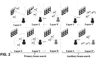
Claims (15)

  1. A method for estimating, at a receiving device (135), characteristics of a channel (BS-UE) between a transmitting device (110) and the receiving device (135), the channel including reflection on a configurable surface (120), the method comprising:
    performing beamforming search for transmission of signals over the channel (BS-UE), thereby obtaining:
    - trained reflection coefficients of the configurable surface (120), and
    - an angle of arrival, AoA, of the signals at the receiving device (135);
    estimating, based on the trained reflection coefficients of the configurable surface (120) and the obtained AoA at the receiving device (135), estimated reflection coefficients of the configurable surface (120) for an ideal channel (BS-RIS) between the transmitting device (110) and the configurable surface (120); and
    estimating, according to a relation between the trained reflection coefficients and the estimated reflection coefficients, characteristics of a channel (BS-RIS) between the transmitting device (110) and the configurable surface (120).
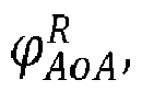
  2. The method according to claim 1, wherein
    estimating the estimated reflection coefficients:
    - comprises a step of estimating an angle of departure, AoD, of the signals at the configurable surface from the AoA at the receiving device (135); and
    - is based on the estimated AoD at the configurable surface.
  3. The method according to claim 2, wherein
    the reflection coefficients are estimated according to following formulas ϕ n , m θ AoA R φ AoA R θ AoD R φ AoD R = γ n , m e n , m ,
    Figure imgb0187
    α n , m = mod 2 π λ m 1 2 Γ x dx + n 1 2 Γ y dy , 2 π ,
    Figure imgb0188
    Γ x = sin θ AoA R cos φ AoA R + sin θ AoD R cos φ AoD R ,
    Figure imgb0189
    and Γ y = sinθ AoA R sinφ AoA R + sinθ AoD R sinφ AoD R ,
    Figure imgb0190
    wherein
    - φn,m is a reflection coefficient of the (n, m)-th element of the configurable surface,
    - γn,m is a reflection gain of the (n, m)-th element of the configurable surface, the γn,m being predetermined,
    - j is the imaginary unit,
    - λ the wavelength of the signal,
    - dx is a separation between elements of the configurable surface in an x-direction,
    - dy is a separation between elements of the configurable surface in an y-direction,
    - θ AoA R
    Figure imgb0191
    is a predetermined elevation AoA at the configurable surface,
    - φ AoA R
    Figure imgb0192
    is an predetermined azimuth AoA at the configurable surface,
    - θ AoD R
    Figure imgb0193
    is an elevation AoD of the estimated AoD at the configurable surface, and
    - φ AoD R
    Figure imgb0194
    is an azimuth AoD of the estimated AoD at the configurable surface.
  4. The method according to claim 3, wherein
    the estimated characteristics of the non-ideal channel (BS-RIS) are a modified channel matrix obtained in accordance with the relation G ^ = Θ 1 Θ θ AoA R φ AoA R θ AoD R φ AoD R G opt θ AoA R φ AoA R θ AoD B φ AoD B ,
    Figure imgb0195
    wherein:
    - Θ θ AoA R φ AoA R θ AoD R φ AoD R
    Figure imgb0196
    is a diagonal matrix comprising the estimated reflection coefficients on its diagonal, Θ = diag{vec(φn,m )};
    - G opt θ AoA R φ AoA R θ AoD B φ AoD B
    Figure imgb0197
    is a channel matrix of the ideal channel (BS-RIS) between the transmitting device (110) and the configurable surface (120), wherein θ AoD B
    Figure imgb0198
    and φ AoD B
    Figure imgb0199
    are respectively the elevation and azimuth AoD at the base station for the ideal channel, and θ AoA R
    Figure imgb0200
    and φ AoA R
    Figure imgb0201
    are respectively the elevation and azimuth AoAs at the configurable surface for the ideal channel;
    - Θ V' is a diagonal matrix comprising the trained reflection coefficients on its diagonal; and
    - (Θ V' )-1 is an inverse matrix of the diagonal matrix Θ V' .
  5. The method according to claim 4, wherein
    the modified channel matrix corresponds to a matrix obtained from a channel matrix G of the channel between the transmitting device (110) and the configurable surface (120) by setting an absolute value of each element of the channel matrix G to one, and
    the method further comprises a step of determining, based on the modified channel matrix , a modified channel matrix .
  6. The method according to claim 5, wherein the modified channel matrix is determined by an iterative reweighting algorithm.
  7. The method according to any of claims 1 to 6, wherein
    the trained reflection coefficients are configured by the transmitting device.
  8. The method according to any of claims 1 to 7, wherein the beamforming search comprises a hierarchic beamforming search including a first stage in which the beamforming search is performed in a plurality, V, of layers, wherein for each current layer following the first layer of the plurality of layer:
    - a predefined number of beams is searched to find a best beam in the current layer, wherein beams of the predefined number of beams searched are selected based on a best beam of a layer immediately preceding the current layer; and
    - in the current layer a number of antennas contributing to the beamforming is increased compared to the layer immediately preceding the current layer.
  9. The method according to claim 8, wherein the hierarchic beamforming search further includes a second stage in which a plurality of beams in a vicinity of the beam found after the first stage are searched.
  10. A method for tracking a location of a receiving device, the method comprising:
    the method according to any of claims 1 to 9, for estimating, at the receiving device (135), the characteristics of the channel (BS-UE) between the transmitting device (110) and the receiving device (135), and
    tracking, based on the characteristics of the channel (BS-UE) between the transmitting device (110) and the receiving device (135) and/or the modified channel matrix Ĥ, the location of the communication device.
  11. The method according to claim 10 for tracking the location of the receiving device using extended Kalman filtering or least mean square, LMS, based tracking.
  12. A computer program product comprising a non-transitory computer-readable medium comprising code instructions which, when executed on one or more processors, cause the one or more processors to perform the method according to any of claims 1 to 11.
  13. An apparatus for estimating, at a receiving device (135), characteristics of a channel (BS-UE) between a transmitting device (110) and the receiving device (135), the channel including reflection on a configurable surface (120), comprising:
    processing circuitry configured to:
    control a transceiver of the receiving the device (135) to perform beamforming search for transmission of signals over the channel (BS-UE), thereby obtaining:
    - trained reflection coefficients of the configurable surface (120), and
    - an angle of arrival, AoA, of the signals at the receiving device (135);
    estimate, based on the configurable surface (120) and the obtained AoA at the receiving device (135), estimated reflection coefficients of the configurable surface (120) for an ideal channel (BS-RIS) between the transmitting device (110) and the configurable surface (120); and
    estimate, according to a relation between the trained reflection coefficients and the estimated reflection coefficients, characteristics of a channel (BS-RIS) between the transmitting device (110) and the configurable surface (120).
  14. A communication device comprising:
    the apparatus for channel estimation according to claim 13; and
    the transceiver.
  15. A method for setting, by a transmitting device (110), reflection coefficients of a configurable surface (120), the method comprising:
    performing beamforming search for transmission of signals over a channel (BS-UE) between the transmitting device (110) and a receiving device (135), the channel including reflection on the configurable surface (120), thereby obtaining:
    - trained reflection coefficients of the configurable surface (120), and
    - an angle of arrival, AoA, of the signals at the receiving device (135);
    estimating an angle of departure, AoD, of the signals at the configurable surface from the AoA at the receiving device (135);
    estimating, based on the configurable surface (120) and the obtained AoA at the receiving device (135), estimated reflection coefficients of the configurable surface (120) for an ideal channel (BS-RIS) between the transmitting device (110) and the configurable surface (120);
    estimating, according to a relation between the trained reflection coefficients and the estimated reflection coefficients, characteristics of a channel (BS-RIS) between the transmitting device (110) and the configurable surface (120); and
    setting the reflection coefficients of the configurable surface (120) according to Θ = Θ θ AoA R φ AoA R θ des φ des G opt G ^ H G ^ G ^ H 1 ,
    Figure imgb0202
    wherein
    - Θ V' is a diagonal matrix comprising the trained reflection coefficients on its diagonal,
    - θdes is a target elevation AoD at the configurable surface (120),
    - ϕdes is a target azimuth AoD at the configurable surface (120),
    - θ AoA R
    Figure imgb0203
    is a predetermined elevation AoA at the configurable surface,
    - φ AoA R
    Figure imgb0204
    is an predetermined azimuth AoA at the configurable surface,
    - θ AoD R
    Figure imgb0205
    is an elevation AoD of the estimated AoD at the configurable surface; and
    - φ AoD R
    Figure imgb0206
    is an azimuth AoD of the estimated AoD at the configurable surface.
EP20193900.6A 2020-09-01 2020-09-01 Channel estimation for configurable surfaces Pending EP3962006A1 (en)

Priority Applications (6)

Application Number Priority Date Filing Date Title
EP20193900.6A EP3962006A1 (en) 2020-09-01 2020-09-01 Channel estimation for configurable surfaces
US18/043,349 US12362967B2 (en) 2020-09-01 2021-09-01 Channel estimation for configurable surfaces
KR1020237011250A KR102674410B1 (en) 2020-09-01 2021-09-01 Channel estimation for configurable surfaces
CN202180053956.6A CN116057852B (en) 2020-09-01 2021-09-01 Channel estimation for configurable surfaces
PCT/EP2021/074113 WO2022049112A1 (en) 2020-09-01 2021-09-01 Channel estimation for configurable surfaces
JP2023507287A JP7571280B2 (en) 2020-09-01 2021-09-01 Channel Estimation for Constructable Surfaces

Applications Claiming Priority (1)

Application Number Priority Date Filing Date Title
EP20193900.6A EP3962006A1 (en) 2020-09-01 2020-09-01 Channel estimation for configurable surfaces

Publications (1)

Publication Number Publication Date
EP3962006A1 true EP3962006A1 (en) 2022-03-02

Family

ID=72322386

Family Applications (1)

Application Number Title Priority Date Filing Date
EP20193900.6A Pending EP3962006A1 (en) 2020-09-01 2020-09-01 Channel estimation for configurable surfaces

Country Status (6)

Country Link
US (1) US12362967B2 (en)
EP (1) EP3962006A1 (en)
JP (1) JP7571280B2 (en)
KR (1) KR102674410B1 (en)
CN (1) CN116057852B (en)
WO (1) WO2022049112A1 (en)

Cited By (22)

* Cited by examiner, † Cited by third party
Publication number Priority date Publication date Assignee Title
CN115021864A (en) * 2022-04-29 2022-09-06 北京邮电大学 Reconfigurable smart surface channel feedback system and its electronic device and medium
CN115103373A (en) * 2022-06-24 2022-09-23 华南理工大学 Deployment method, system and medium for reconfigurable intelligent surface physical inclination angle
CN115189989A (en) * 2022-04-29 2022-10-14 北京邮电大学 Method for channel estimation, electronic device and medium thereof
CN115412187A (en) * 2022-07-10 2022-11-29 重庆邮电大学 Millimeter wave channel tracking method based on reconfigurable intelligent surface
US20220405602A1 (en) * 2021-06-21 2022-12-22 Qualcomm Incorporated Channel feature extraction via model-based neural networks
CN115865289A (en) * 2022-04-13 2023-03-28 中兴通讯股份有限公司 Channel separation method and system
CN116133009A (en) * 2023-02-15 2023-05-16 重庆邮电大学 System backward link optimization method and system combining IRS and wireless power supply
CN116318295A (en) * 2022-12-07 2023-06-23 电子科技大学长三角研究院(湖州) Beam search method based on high frequency band information
CN116527093A (en) * 2022-12-15 2023-08-01 东南大学 Beam forming method of double-time-scale intelligent reflection surface auxiliary system
JP2023138186A (en) * 2022-03-19 2023-10-02 株式会社国際電気通信基礎技術研究所 Estimation device, wireless communication system equipped with the same, and program to be executed by a computer
WO2023201668A1 (en) * 2022-04-21 2023-10-26 北京小米移动软件有限公司 Acquisition method for pilot frequency position determination model, determination method for pilot frequency position, and apparatuses thereof
EP4300838A1 (en) * 2022-06-29 2024-01-03 Fondation B-COM Method and device for configuring a communication device for data transmission between an emitter and a receiver
EP4344085A1 (en) 2022-09-20 2024-03-27 Rohde & Schwarz GmbH & Co. KG Measuring characteristics of a reconfigurable intelligent surface
US20240162960A1 (en) * 2021-03-08 2024-05-16 Telefonaktiebolaget Lm Ericsson (Publ) Channel information estimation for communication networks with meta-surfaces
WO2024163780A1 (en) * 2023-02-03 2024-08-08 Interdigital Patent Holdings, Inc. Decomposition-based separated channel estimation and sounding for reconfigurable intelligent surfaces
WO2024171093A1 (en) * 2023-02-15 2024-08-22 Politecnico Di Milano Wireless communications with space-time modulated metasurfaces
EP4425799A1 (en) * 2023-03-02 2024-09-04 Fondation B Com Method and device for generating a codebook for precoding reflecting elements of a communication device
WO2024183873A1 (en) * 2023-03-03 2024-09-12 Telefonaktiebolaget Lm Ericsson (Publ) Horizontal and vertical beamforming design for irs-assisted communications
US20250007566A1 (en) * 2021-12-10 2025-01-02 Qualcomm Incorporated Beam acquisition for a reconfigurable intelligent surface
CN119766601A (en) * 2025-03-10 2025-04-04 华东交通大学 Channel estimation method for intelligent super-surface auxiliary high-speed rail wireless communication
WO2025122078A1 (en) * 2023-12-06 2025-06-12 Telefonaktiebolaget Lm Ericsson (Publ) Reducing reflection squint in a wireless communications network
EP4496255A4 (en) * 2022-04-25 2025-10-08 Zte Corp DOA DETERMINATION METHOD AND DEVICE, STORAGE MEDIUM AND ELECTRONIC DEVICE

Families Citing this family (37)

* Cited by examiner, † Cited by third party
Publication number Priority date Publication date Assignee Title
EP4264851A4 (en) * 2020-12-17 2024-06-19 Istanbul Medipol Universitesi GROUP-BASED MULTIPLEXING OF RADAR AND COMMUNICATION SIGNALS IN A MILLIMETER WAVE BAND
WO2022146830A2 (en) * 2021-01-04 2022-07-07 Google Llc Integrated access backhaul with an adaptive phase-changing device
US20240007147A1 (en) * 2021-01-14 2024-01-04 Qualcomm Incorporated Communicating reconfigurable intelligent surface (ris) information to support ris-division multiple access
WO2022164596A1 (en) * 2021-01-28 2022-08-04 Qualcomm Incorporated Reconfigurable intelligent surface (ris)-aided ue passive rf sensing
JP7715200B2 (en) * 2021-09-24 2025-07-30 富士通株式会社 Base station device, terminal device, wireless communication system, and wireless communication method
US20240388328A1 (en) * 2021-11-30 2024-11-21 Qualcomm Incorporated Precoding combiners for reconfigurable intelligent surface (ris) aided communications
WO2023113666A1 (en) * 2021-12-17 2023-06-22 Telefonaktiebolaget Lm Ericsson (Publ) Ue-side beam selection procedure
CN114745232B (en) * 2022-04-02 2023-08-11 上海应用技术大学 Channel Estimation Method for Smart Reconfigurable Surface-Assisted Millimeter-Wave MIMO Systems
CN114866377B (en) * 2022-04-28 2024-05-28 西安交通大学 Reflection channel estimation method based on pilot reconstruction in RIS-assisted communication of industrial Internet of Things
WO2023216164A1 (en) * 2022-05-11 2023-11-16 北京小米移动软件有限公司 Intelligent metasurface precoding method and apparatus
CN115866742A (en) * 2022-05-25 2023-03-28 中兴通讯股份有限公司 Positioning method, device, equipment, storage medium and program product
CN115189789B (en) * 2022-06-14 2023-10-31 北京理工大学长三角研究院(嘉兴) Low-complexity intelligent metasurface phase control method for physical layer secure communication
CN115022146B (en) * 2022-07-25 2023-05-26 电子科技大学 Communication and positioning integrated full duplex system with reconfigurable intelligent surface assistance
WO2024020904A1 (en) * 2022-07-27 2024-02-01 北京小米移动软件有限公司 Method for sending phase shift configuration of intelligent reflecting surface (irs), method for receiving phase shift configuration of irs, and apparatus
US20240097743A1 (en) * 2022-09-15 2024-03-21 Apple Inc. Systems and Methods for Controlling Reconfigurable Intelligent Surfaces
EP4589893A4 (en) * 2022-09-16 2025-10-22 Beijing Xiaomi Mobile Software Co Ltd Precoding method and apparatus based on reconfigurable intelligent surface
CN115483957B (en) * 2022-09-20 2024-01-09 华工未来科技(江苏)有限公司 Phase regulation method and device for RIS auxiliary communication system, electronic equipment and medium
US12546808B2 (en) 2022-10-12 2026-02-10 Rohde & Schwarz Gmbh & Co. Kg Test system and test method
KR20240053303A (en) 2022-10-17 2024-04-24 삼성전자주식회사 Apparatus and method for performing a beam sweeping using ris pattern in a wireless communication system
WO2024085265A1 (en) * 2022-10-17 2024-04-25 삼성전자 주식회사 Device and method for performing beam sweeping by using ris pattern in wireless communication system
KR20240055505A (en) 2022-10-20 2024-04-29 삼성전자주식회사 Apparatus and method for transmitting and receiving a signal in wireless communication system
WO2024085279A1 (en) * 2022-10-20 2024-04-25 삼성전자 주식회사 Method and apparatus for transmitting and receiving signal in wireless communication system
KR20240099078A (en) 2022-12-20 2024-06-28 한국전자통신연구원 Method and apparatus for codebook design in communication system
CN118432980A (en) * 2023-02-01 2024-08-02 大唐移动通信设备有限公司 Channel estimation method, device and storage medium
WO2024192699A1 (en) * 2023-03-22 2024-09-26 Qualcomm Incorporated Updating coefficients for reconfigurable surface
WO2024211125A1 (en) * 2023-04-04 2024-10-10 Kyocera Corporation Methods, apparatuses and systems for intelligent reflection surface installed user equipment channel estimation
WO2025048012A1 (en) * 2023-08-31 2025-03-06 엘지전자 주식회사 Apparatus and method for transmitting signal by using metasurface installed in limited space in wireless communication system
CN121420487A (en) * 2023-10-20 2026-01-27 株式会社Ntt都科摩 Relay devices, base stations, and wireless communication methods
CN117278159B (en) * 2023-10-27 2024-11-15 北京邮电大学 Reconfigurable intelligent surface channel modeling method, device, equipment and medium
KR20250069135A (en) * 2023-11-10 2025-05-19 강원대학교산학협력단 Beamforming method and device in ris element grouping
CN118119003B (en) * 2024-04-03 2024-10-22 南通大学 A method and device for allocating multipath signal power
CN121174256A (en) * 2024-06-19 2025-12-19 华为技术有限公司 Communication method and device
CN118740562B (en) * 2024-07-05 2025-09-05 北京邮电大学 Channel parameter estimation method, device, electronic device and storage medium
CN119110303A (en) * 2024-08-22 2024-12-10 中国人民解放军国防科技大学 A three-dimensional near-field coverage method, device and equipment based on RIS array
CN119814503B (en) * 2025-02-27 2026-01-30 西安电子科技大学 A segmented channel estimation method, system, device and medium for a RIS-assisted system
CN119986621B (en) * 2025-04-17 2025-07-04 南京理工大学 RIS auxiliary MIMO radar transmitting beam forming method based on beam pattern matching
CN120455210A (en) * 2025-05-08 2025-08-08 杭州电子科技大学 Semi-active IRS system channel estimation method and system based on random and fixed sampling

Family Cites Families (13)

* Cited by examiner, † Cited by third party
Publication number Priority date Publication date Assignee Title
EP2169888A1 (en) 2008-09-30 2010-03-31 NTT DoCoMo Inc. A three dimensional pilot aided radio channel estimator
US9279880B2 (en) * 2014-07-15 2016-03-08 Applied Signals Intelligence, Inc. Electrically small, range and angle-of-arrival RF sensor and estimation system
KR20180026470A (en) * 2015-07-29 2018-03-12 퀄컴 인코포레이티드 Angle and position detection using arrays of antennas
US9948377B1 (en) * 2017-02-06 2018-04-17 Mitsubishi Electric Research Laboratories, Inc. System and method for spatial beamforming modulation
CN107040296B (en) * 2017-02-28 2020-05-26 北京航空航天大学 Channel estimation method in millimeter wave communication
CN107634787A (en) 2017-08-22 2018-01-26 南京邮电大学 A Method for Massive MIMO Millimeter Wave Channel Estimation
US10594517B1 (en) * 2018-10-26 2020-03-17 Wistron Neweb Corporation Channel estimation system and method thereof
CN109861933B (en) 2018-11-28 2021-11-26 中国传媒大学 Millimeter wave MIMO channel estimation method based on MUSIC algorithm and precoding
CN110022274B (en) 2018-12-24 2022-03-25 深圳先进技术研究院 Joint channel and carrier frequency offset estimation method of millimeter wave MIMO-OFDM system
CN110519189B (en) 2019-08-30 2022-12-09 东南大学 Compressed Sensing Based Millimeter Wave Channel Estimation Method in Highly Mobile Scenarios
WO2021221603A1 (en) * 2020-04-27 2021-11-04 Nokia Technologies Oy Ue positioning aided by reconfigurable reflecting surfaces such as intelligent reflecting surfaces (irs)
BR112022014956A2 (en) 2020-07-02 2023-01-10 Zte Corp SURFACE ELEMENT SEGMENTATION AND NODE GROUPING FOR INTELLIGENT REFLECTOR DEVICES
KR102582131B1 (en) 2022-07-14 2023-09-21 강원대학교산학협력단 Channel estimation apparatus based on hierarchical codebook for mimo system and method thereof

Non-Patent Citations (3)

* Cited by examiner, † Cited by third party
Title
JIA C ET AL: "High-Resolution Channel Estimation for Intelligent Reflecting Surface-Assisted MmWave Communications", ARXIV.ORG, CORNELL UNIVERSITY LIBRARY, 201 OLIN LIBRARY CORNELL UNIVERSITY ITHACA, NY 14853, 21 June 2020 (2020-06-21), XP081699747 *
JIGUANG HE ET AL: "Channel Estimation for RIS-Aided mmWave MIMO Channels", ARXIV.ORG, CORNELL UNIVERSITY LIBRARY, 201 OLIN LIBRARY CORNELL UNIVERSITY ITHACA, NY 14853, 15 February 2020 (2020-02-15), XP081600796 *
NING BOYU ET AL: "Channel Estimation and Transmission for Intelligent Reflecting Surface Assisted THz Communications", ICC 2020 - 2020 IEEE INTERNATIONAL CONFERENCE ON COMMUNICATIONS (ICC), IEEE, 7 June 2020 (2020-06-07), pages 1 - 7, XP033798166, [retrieved on 20200724], DOI: 10.1109/ICC40277.2020.9149153 *

Cited By (28)

* Cited by examiner, † Cited by third party
Publication number Priority date Publication date Assignee Title
US20240162960A1 (en) * 2021-03-08 2024-05-16 Telefonaktiebolaget Lm Ericsson (Publ) Channel information estimation for communication networks with meta-surfaces
US20220405602A1 (en) * 2021-06-21 2022-12-22 Qualcomm Incorporated Channel feature extraction via model-based neural networks
US12561571B2 (en) * 2021-06-21 2026-02-24 Qualcomm Incorporated Channel feature extraction via model-based neural networks
US20250007566A1 (en) * 2021-12-10 2025-01-02 Qualcomm Incorporated Beam acquisition for a reconfigurable intelligent surface
JP2023138186A (en) * 2022-03-19 2023-10-02 株式会社国際電気通信基礎技術研究所 Estimation device, wireless communication system equipped with the same, and program to be executed by a computer
CN115865289A (en) * 2022-04-13 2023-03-28 中兴通讯股份有限公司 Channel separation method and system
WO2023201668A1 (en) * 2022-04-21 2023-10-26 北京小米移动软件有限公司 Acquisition method for pilot frequency position determination model, determination method for pilot frequency position, and apparatuses thereof
EP4496255A4 (en) * 2022-04-25 2025-10-08 Zte Corp DOA DETERMINATION METHOD AND DEVICE, STORAGE MEDIUM AND ELECTRONIC DEVICE
CN115021864A (en) * 2022-04-29 2022-09-06 北京邮电大学 Reconfigurable smart surface channel feedback system and its electronic device and medium
CN115189989A (en) * 2022-04-29 2022-10-14 北京邮电大学 Method for channel estimation, electronic device and medium thereof
CN115189989B (en) * 2022-04-29 2023-11-17 北京邮电大学 Channel estimation method, electronic device and medium thereof
CN115021864B (en) * 2022-04-29 2024-03-22 北京邮电大学 Reconfigurable intelligent surface channel feedback system, electronic equipment and medium thereof
CN115103373A (en) * 2022-06-24 2022-09-23 华南理工大学 Deployment method, system and medium for reconfigurable intelligent surface physical inclination angle
EP4300838A1 (en) * 2022-06-29 2024-01-03 Fondation B-COM Method and device for configuring a communication device for data transmission between an emitter and a receiver
WO2024002617A1 (en) * 2022-06-29 2024-01-04 Fondation B-Com Method and device for configuring a communication device for data transmission between an emitter and a receiver
CN115412187A (en) * 2022-07-10 2022-11-29 重庆邮电大学 Millimeter wave channel tracking method based on reconfigurable intelligent surface
EP4344085A1 (en) 2022-09-20 2024-03-27 Rohde & Schwarz GmbH & Co. KG Measuring characteristics of a reconfigurable intelligent surface
CN116318295A (en) * 2022-12-07 2023-06-23 电子科技大学长三角研究院(湖州) Beam search method based on high frequency band information
CN116318295B (en) * 2022-12-07 2025-12-12 电子科技大学长三角研究院(湖州) Beam Search Method Based on High-Frequency Band Information
CN116527093A (en) * 2022-12-15 2023-08-01 东南大学 Beam forming method of double-time-scale intelligent reflection surface auxiliary system
WO2024163780A1 (en) * 2023-02-03 2024-08-08 Interdigital Patent Holdings, Inc. Decomposition-based separated channel estimation and sounding for reconfigurable intelligent surfaces
WO2024171093A1 (en) * 2023-02-15 2024-08-22 Politecnico Di Milano Wireless communications with space-time modulated metasurfaces
CN116133009A (en) * 2023-02-15 2023-05-16 重庆邮电大学 System backward link optimization method and system combining IRS and wireless power supply
EP4425799A1 (en) * 2023-03-02 2024-09-04 Fondation B Com Method and device for generating a codebook for precoding reflecting elements of a communication device
WO2024180097A1 (en) * 2023-03-02 2024-09-06 Fondation B-Com Method and device for generating a codebook for precoding reflecting elements of a communication device
WO2024183873A1 (en) * 2023-03-03 2024-09-12 Telefonaktiebolaget Lm Ericsson (Publ) Horizontal and vertical beamforming design for irs-assisted communications
WO2025122078A1 (en) * 2023-12-06 2025-06-12 Telefonaktiebolaget Lm Ericsson (Publ) Reducing reflection squint in a wireless communications network
CN119766601A (en) * 2025-03-10 2025-04-04 华东交通大学 Channel estimation method for intelligent super-surface auxiliary high-speed rail wireless communication

Also Published As

Publication number Publication date
KR20230058512A (en) 2023-05-03
KR102674410B1 (en) 2024-06-13
CN116057852A (en) 2023-05-02
JP2023538822A (en) 2023-09-12
US12362967B2 (en) 2025-07-15
CN116057852B (en) 2025-01-14
WO2022049112A1 (en) 2022-03-10
US20230421412A1 (en) 2023-12-28
JP7571280B2 (en) 2024-10-22

Similar Documents

Publication Publication Date Title
US12362967B2 (en) Channel estimation for configurable surfaces
Zegrar et al. A general framework for RIS-aided mmWave communication networks: Channel estimation and mobile user tracking
Araújo et al. Channel estimation for millimeter-wave very-large MIMO systems
CN111052619A (en) Electronic equipment and communication method
KR102266761B1 (en) Beamforming method and device
US10382110B2 (en) Adaptive user-specific beam forming
US20240405830A1 (en) Beamforming solution for mimo communication
CN113131979A (en) Transmission method and network side equipment
JP2010166316A (en) Mimo communication system
Ge et al. Beamforming design with partial channel estimation and feedback for FDD RIS-assisted systems
Tang et al. Downlink precoding for multiple users in FDD massive MIMO without CSI feedback
Nwalozie et al. Reflection design methods for reconfigurable intelligent surfaces-aided dynamic TDD systems
Kumbar Adaptive beamforming smart antenna for wireless communication system
Yağan et al. A novel blind adaptive beamformer with robustness against mutual coupling and miscalibration effects
Okoth et al. An efficient codebook-based beam training technique for millimeter-wave communication systems
Lee et al. Piecewise Beam Training and Channel Estimation for RIS-Aided Near-Field Communications
US20240072911A1 (en) Calibration of transmit antenna chains and receive antenna chains of an antenna system
Adeogun et al. Channel prediction for millimeter wave MIMO systems in 3D propagation environments
Tapio et al. Coverage enhancements using RIS-integrated NR
WO2017084588A1 (en) System and method for multi-source channel estimation
US12407381B2 (en) Communication method and apparatus
Wang et al. Hybrid 3D beamforming relying on sensor-based training and channel estimation for reconfigurable intelligent surface aided terahertz MIMO systems
WO2026040921A1 (en) Near-field access channel estimation and beam-focusing techniques for reconfigurable intelligent surface-assisted cellular networks in wireless communications
Gavriilidis et al. Sensing-Aided Near-Field Beam Tracking
Viteri-Mera et al. Beam selection in multiuser millimeter-wave systems with sub-array user terminal architectures

Legal Events

Date Code Title Description
PUAI Public reference made under article 153(3) epc to a published international application that has entered the european phase

Free format text: ORIGINAL CODE: 0009012

STAA Information on the status of an ep patent application or granted ep patent

Free format text: STATUS: THE APPLICATION HAS BEEN PUBLISHED

AK Designated contracting states

Kind code of ref document: A1

Designated state(s): AL AT BE BG CH CY CZ DE DK EE ES FI FR GB GR HR HU IE IS IT LI LT LU LV MC MK MT NL NO PL PT RO RS SE SI SK SM TR

STAA Information on the status of an ep patent application or granted ep patent

Free format text: STATUS: REQUEST FOR EXAMINATION WAS MADE

17P Request for examination filed

Effective date: 20220826

RBV Designated contracting states (corrected)

Designated state(s): AL AT BE BG CH CY CZ DE DK EE ES FI FR GB GR HR HU IE IS IT LI LT LU LV MC MK MT NL NO PL PT RO RS SE SI SK SM TR

STAA Information on the status of an ep patent application or granted ep patent

Free format text: STATUS: EXAMINATION IS IN PROGRESS

17Q First examination report despatched

Effective date: 20240214