EP3961913A1 - Fail-safe motor control architecture for open-end winding motors - Google Patents
Fail-safe motor control architecture for open-end winding motors Download PDFInfo
- Publication number
- EP3961913A1 EP3961913A1 EP21190453.7A EP21190453A EP3961913A1 EP 3961913 A1 EP3961913 A1 EP 3961913A1 EP 21190453 A EP21190453 A EP 21190453A EP 3961913 A1 EP3961913 A1 EP 3961913A1
- Authority
- EP
- European Patent Office
- Prior art keywords
- motor
- switch
- control system
- terminal
- motor control
- Prior art date
- Legal status (The legal status is an assumption and is not a legal conclusion. Google has not performed a legal analysis and makes no representation as to the accuracy of the status listed.)
- Granted
Links
Images


Classifications
-
- H—ELECTRICITY
- H02—GENERATION; CONVERSION OR DISTRIBUTION OF ELECTRIC POWER
- H02P—CONTROL OR REGULATION OF ELECTRIC MOTORS, ELECTRIC GENERATORS OR DYNAMO-ELECTRIC CONVERTERS; CONTROLLING TRANSFORMERS, REACTORS OR CHOKE COILS
- H02P29/00—Arrangements for regulating or controlling electric motors, appropriate for both AC and DC motors
- H02P29/02—Providing protection against overload without automatic interruption of supply
- H02P29/024—Detecting a fault condition, e.g. short circuit, locked rotor, open circuit or loss of load
- H02P29/028—Detecting a fault condition, e.g. short circuit, locked rotor, open circuit or loss of load the motor continuing operation despite the fault condition, e.g. eliminating, compensating for or remedying the fault
-
- H—ELECTRICITY
- H02—GENERATION; CONVERSION OR DISTRIBUTION OF ELECTRIC POWER
- H02P—CONTROL OR REGULATION OF ELECTRIC MOTORS, ELECTRIC GENERATORS OR DYNAMO-ELECTRIC CONVERTERS; CONTROLLING TRANSFORMERS, REACTORS OR CHOKE COILS
- H02P23/00—Arrangements or methods for the control of AC motors characterised by a control method other than vector control
- H02P23/0004—Control strategies in general, e.g. linear type, e.g. P, PI, PID, using robust control
- H02P23/0027—Control strategies in general, e.g. linear type, e.g. P, PI, PID, using robust control using different modes of control depending on a parameter, e.g. the speed
-
- H—ELECTRICITY
- H02—GENERATION; CONVERSION OR DISTRIBUTION OF ELECTRIC POWER
- H02P—CONTROL OR REGULATION OF ELECTRIC MOTORS, ELECTRIC GENERATORS OR DYNAMO-ELECTRIC CONVERTERS; CONTROLLING TRANSFORMERS, REACTORS OR CHOKE COILS
- H02P25/00—Arrangements or methods for the control of AC motors characterised by the kind of AC motor or by structural details
- H02P25/16—Arrangements or methods for the control of AC motors characterised by the kind of AC motor or by structural details characterised by the circuit arrangement or by the kind of wiring
- H02P25/18—Arrangements or methods for the control of AC motors characterised by the kind of AC motor or by structural details characterised by the circuit arrangement or by the kind of wiring with arrangements for switching the windings, e.g. with mechanical switches or relays
-
- H—ELECTRICITY
- H02—GENERATION; CONVERSION OR DISTRIBUTION OF ELECTRIC POWER
- H02P—CONTROL OR REGULATION OF ELECTRIC MOTORS, ELECTRIC GENERATORS OR DYNAMO-ELECTRIC CONVERTERS; CONTROLLING TRANSFORMERS, REACTORS OR CHOKE COILS
- H02P27/00—Arrangements or methods for the control of AC motors characterised by the kind of supply voltage
- H02P27/04—Arrangements or methods for the control of AC motors characterised by the kind of supply voltage using variable-frequency supply voltage, e.g. inverter or converter supply voltage
- H02P27/06—Arrangements or methods for the control of AC motors characterised by the kind of supply voltage using variable-frequency supply voltage, e.g. inverter or converter supply voltage using DC to AC converters or inverters
-
- H—ELECTRICITY
- H02—GENERATION; CONVERSION OR DISTRIBUTION OF ELECTRIC POWER
- H02P—CONTROL OR REGULATION OF ELECTRIC MOTORS, ELECTRIC GENERATORS OR DYNAMO-ELECTRIC CONVERTERS; CONTROLLING TRANSFORMERS, REACTORS OR CHOKE COILS
- H02P29/00—Arrangements for regulating or controlling electric motors, appropriate for both AC and DC motors
- H02P29/02—Providing protection against overload without automatic interruption of supply
- H02P29/024—Detecting a fault condition, e.g. short circuit, locked rotor, open circuit or loss of load
-
- H—ELECTRICITY
- H02—GENERATION; CONVERSION OR DISTRIBUTION OF ELECTRIC POWER
- H02P—CONTROL OR REGULATION OF ELECTRIC MOTORS, ELECTRIC GENERATORS OR DYNAMO-ELECTRIC CONVERTERS; CONTROLLING TRANSFORMERS, REACTORS OR CHOKE COILS
- H02P2207/00—Indexing scheme relating to controlling arrangements characterised by the type of motor
- H02P2207/01—Asynchronous machines
-
- H—ELECTRICITY
- H02—GENERATION; CONVERSION OR DISTRIBUTION OF ELECTRIC POWER
- H02P—CONTROL OR REGULATION OF ELECTRIC MOTORS, ELECTRIC GENERATORS OR DYNAMO-ELECTRIC CONVERTERS; CONTROLLING TRANSFORMERS, REACTORS OR CHOKE COILS
- H02P2207/00—Indexing scheme relating to controlling arrangements characterised by the type of motor
- H02P2207/05—Synchronous machines, e.g. with permanent magnets or DC excitation
Definitions
- the present disclosure generally relates to alternating current motor control, and more particularly relates to a fail-safe motor control architecture for open-end winding motors.
- a motor control system includes a multi-phase motor, a multi-phase inverter circuit, a plurality of controllable switches, a plurality of sensors, and a monitor circuit.
- the multi-phase motor includes a rotor and a plurality of stator windings. Each stator winding is associated with a different phase and includes a first terminal and a second terminal.
- the multi-phase inverter circuit is coupled to the first terminal of each of the stator windings and is responsive to motor command signals to controllably couple the first terminal of one or more of the stator windings to either a power source or a circuit common node.
- Each controllable switch is associated with a different one of the second terminals and is coupled in series between its associated second terminal and a common winding node.
- Each controllable switch is responsive to switch commands to operate in either a first switch mode, in which each controllable switch electrically couples the second terminal of its associated stator winding to the common winding node, or a second switch mode, in which each controllable switch electrically isolates the second terminal of its associated stator winding from the common winding node.
- Each sensor is configured to sense a motor state variable and supply a sensor signal representative of the sensed motor state variable.
- the monitor circuit is coupled to each of the controllable switches and to each of the sensors.
- the monitor circuit is responsive to each of the sensor signals to: determine when one or more of the sensed motor state variables attains a predetermined threshold magnitude, and when one or more of the sensed motor state variables attains the predetermined threshold magnitude, to supply a switch command to one or more of the controllable switches that causes the one or more controllable switches to operate in the second switch mode.
- a motor control system in another embodiment, includes a three-phase motor, a three-phase inverter circuit, a plurality of controllable switches, a plurality of sensors, and a monitor circuit.
- the three-phase motor includes a rotor and a plurality of stator windings. Each stator winding is associated with a different phase and includes a first terminal and a second terminal.
- the three-phase inverter circuit is coupled to the first terminal of each of the stator windings.
- the three-phase inverter circuit is responsive to motor command signals to controllably couple the first terminal of one or more of the stator windings to either a power source or a circuit common node.
- Each controllable switch is associated with a different one of the second terminals and is electrically coupled in series between its associated second terminal and a common winding node.
- Each controllable switch is responsive to switch commands to operate in either a first switch mode, in which each controllable switch electrically couples the second terminal of its associated stator winding to the common winding node, or a second switch mode, in which each controllable switch electrically isolates the second terminal of its associated stator winding from the common winding node.
- Each sensor is configured to sense a motor state variable and supply a sensor signal representative of the sensed motor state variable.
- the monitor circuit is coupled to each of the controllable switches and to each of the sensors.
- the monitor circuit is responsive to each of the sensor signals to determine when one or more of the sensed motor state variables attains a predetermined threshold magnitude and: (i) when none of the sensed motor state variables has attained the predetermined threshold magnitude, to supply a switch command each of the controllable switches that causes each of the controllable switches to operate in the first switch mode, and (ii) when one or more of the sensed motor state variables attains the predetermined threshold magnitude, to supply a switch command to one or more of the controllable switches that causes the one or more controllable switches to operate in the second switch mode.
- a motor control system in yet another embodiment, includes a three-phase motor, a three-phase inverter circuit, a plurality of controllable switches, a plurality of sensors, and a monitor circuit.
- the three-phase motor includes a rotor and a plurality of stator windings. Each stator winding is associated with a different phase and includes a first terminal and a second terminal.
- the three-phase inverter circuit is coupled to the first terminal of each of the stator windings and is responsive to motor command signals to controllably couple the first terminal of one or more of the stator windings to either a power source or a circuit common node.
- the three-phase inverter circuit includes a first pair of series-connected switches, a second pair of series-connected switches, and a third pair of series-connected switches.
- the first terminal of each stator winding is connected between a different one of the first, second, and third pair of series-connected switches.
- Each controllable switch is associated with a different one of the second terminals and is electrically coupled in series between its associated second terminal and a common winding node.
- Each controllable switch is responsive to switch commands to operate in either a first switch mode, in which each controllable switch electrically couples the second terminal of its associated stator winding to the common winding node, or a second switch mode, in which each controllable switch electrically isolates the second terminal of its associated stator winding from the common winding node.
- Each sensor is configured to sense a motor state variable and supply a sensor signal representative of the sensed motor state variable.
- the monitor circuit is coupled to each of the controllable switches and to each of the sensors.
- the monitor circuit is responsive to each of the sensor signals to determine when one or more of the sensed motor state variables attains a predetermined threshold magnitude and: (i) when none of the sensed motor state variables has attained the predetermined threshold magnitude, to supply a switch command each of the controllable switches that causes each of the controllable switches to operate in the first switch mode, and (ii) when one or more of the sensed motor state variables attains the predetermined threshold magnitude, to supply a switch command to one or more of the controllable switches that causes the one or more controllable switches to operate in the second switch mode.
- the depicted system 100 includes a multi-phase motor 102, a multi-phase inverter circuit 104, a plurality of controllable switches 106, a plurality of sensors 108, and a monitor circuit 112.
- the multi-phase motor 102 includes a rotor 114 and a plurality of stator windings 116.
- the motor 102 may be implemented as any one of numerous multi-phase motors, such as a permanent magnet synchronous motor (PMSM), a brushless direct current (BLDC) motor, or as an asynchronous motor, just to name a few.
- PMSM permanent magnet synchronous motor
- BLDC brushless direct current
- the rotor 114 is configured to rotate upon a torque being applied thereto. As is generally known, when the stator windings 116 are energized, a torque is generated and applied to the rotor 114. The rotor 114 thus rotates in the direction and speed of the applied torque. Although the rotor 114 may be variously configured and implemented, in one particular embodiment, such as the embodiment depicted in FIG. 2 , the rotor 114 is implemented as a permanent magnet rotor.
- the multi-phase stator 116 is implemented with a plurality of individual, electrically isolated stator windings, and each stator winding is associated with a different phase. It will be appreciated that the stator 116 may be variously configured and implemented, but in one particular embodiment, such as the one depicted in FIG. 2 , the multi-phase stator includes three individual, electrically isolated stator windings 118 (e.g., 118-1, 118-2, 118-3). Each stator winding 118 includes two terminals 122, a first terminal 122-1 and a second terminal 122-2. It will be appreciated that the stator windings 118 may be configured as three-phase wye windings, as depicted in FIG. 2 , or as three-phase delta windings.
- the stator windings 118 may be configured as three-phase wye windings, as depicted in FIG. 2 , or as three-phase delta windings.
- the multi-phase inverter circuit 104 is coupled to the first terminal 122-1 of each of the stator windings 118.
- the multi-phase inverter circuit 104 is responsive to motor command signals to controllably couple the first terminal 112-1 of one or more of the stator windings 118 to either a power source 124 or a circuit common node 126, to thereby energize one or more of the stator windings 118.
- the multi-phase inverter circuit 104 may be configured as any one of numerous known inverter topologies to implement this functionality. In one particular embodiment, such as the one depicted in FIG. 2 , the multi-phase inverter circuit 104 includes a plurality of series-connected switches 128 and a controller 132.
- first pair of series-connected switches 128-1 includes a first pair of series-connected switches 128-1, a second pair of series-connected switches 128-2, and a third pair of series-connected switches 128-3, where the first terminal 112-1 of each stator winding 118 is connected between a different one of the first, second, and third pair of series-connected switches 128.
- the series-connected switches 128 are each implemented using suitable field effect transistors (FETs), but could also be implemented using any one of numerous other suitable switch devices, now known or developed in the future.
- FETs field effect transistors
- the controller 132 is coupled to receive motor command signals 134 and feedback signals from one or more of the sensors 108.
- the controller 132 is configured, in response to the motor command signal 134 and the feedback signals, to command the series-connected switches 128, using any one of numerous know commutation schemes, to controllably couple the first terminal 112-1 of one or more of the stator windings 118 to either the power source 124 or the circuit common node 126.
- the controller 132 may be implemented using one or more processors and computer-readable storage devices or media encoded with programming instructions for configuring the controller 132.
- the one or more processors may be any custom-made or commercially available processor, a central processing unit (CPU), a graphics processing unit (GPU), an application specific integrated circuit (ASIC), a field programmable gate array (FPGA), a digital signal controller (DSC), an auxiliary processor among several processors associated with the controller, a semiconductor-based microprocessor (in the form of a microchip or chip set), any combination thereof, or generally any device for executing instructions.
- CPU central processing unit
- GPU graphics processing unit
- ASIC application specific integrated circuit
- FPGA field programmable gate array
- DSC digital signal controller
- auxiliary processor among several processors associated with the controller
- semiconductor-based microprocessor in the form of a microchip or chip set
- any combination thereof or generally any device for executing instructions.
- the computer readable storage devices or media may include volatile and nonvolatile storage in read-only memory (ROM), random-access memory (RAM), and keep-alive memory (KAM), for example.
- KAM is a persistent or non-volatile memory that may be used to store various operating variables while the processor is powered down.
- the computer-readable storage device or media may be implemented using any of a number of known memory devices such as PROMs (programmable read-only memory), EPROMs (electrically PROM), EEPROMs (electrically erasable PROM), flash memory, or any other electric, magnetic, optical, or combination memory devices capable of storing data, some of which represent executable programming instructions, used by the controller 132.
- the controllable switches 106 are each associated with a different one of the second terminals 122-2, and each controllable switch 106 is electrically coupled in series between its associated second terminal 122-2 and a common winding node 128.
- the system 100 includes three controllable switches 106-1, 106-2, 106-3, and each is responsive to switch commands to operate in either a first switch mode or a second switch mode.
- each controllable switch 106 electrically couples the second terminal 122-2 of its associated stator winding 118 to the common winding node 128.
- each controllable switch 106 electrically isolates the second terminal 122-2 of its associated stator winding 118 from the common winding node 128.
- the controllable switches 106 may be implemented using any one of numerous types of switches, including any one of numerous types of manually-actuated switches, any one of numerous types of electromechanical switches (e.g., relays, contactors, etc.), any one of numerous types of solid state semiconductor switches (e.g., MOSFETs, FETs, bipolar transistors, etc.), or various combinations thereof, or any other suitable type of switch now known or developed in the future.
- switches including any one of numerous types of manually-actuated switches, any one of numerous types of electromechanical switches (e.g., relays, contactors, etc.), any one of numerous types of solid state semiconductor switches (e.g., MOSFETs, FETs, bipolar transistors, etc.), or various combinations thereof, or any other suitable type of switch now known or developed in the future.
- Each of the sensors 108 is configured to sense a motor state variable and supply a sensor signal representative of the sensed motor state variable to at least the monitor circuit 112. In some instances, one or more of the sensed motor state variables may also be supplied to the multi-phase inverter circuit 104.
- the plurality of sensors 108 may vary in type, location, and configuration. In one particular embodiment, the sensors 108 include at least a plurality of monitor circuit current sensors 108-1 and a plurality of inverter circuit current sensors 108-2, but may also include a position sensor 108-3 (see FIG. 2 ), and a speed sensor (not depicted), just to name a few.
- Each of the current sensors 108-1, 108-2 is configured to sense current flow through a different one of the stator windings 118-1, 118-2, 118-3, and supplies signals representative thereof.
- the monitor current sensors 108-1 supply the signals to the monitor circuit 112
- the inverter current sensors 108-2 supply the signals to the multi-phase inverter circuit 104.
- the position sensor 108-3 when included, senses the rotational position of the rotor 114, and supplies position feedback signals to the multi-phase inverter circuit 104 and the monitor circuit 112.
- the speed sensor when included, senses the rotational speed of the rotor 114, and supplies speed (or rate) feedback signals to the multi-phase inverter circuit 104 and the monitor circuit 112.
- the speed feedback signal may be derived from the position feedback signal.
- the sensors 108 can be disposed internally or externally to the motor, be implemented as part of the multi-phase inverter circuit 104 and/or the monitor circuit 112, or be implemented as a completely separate circuit, or various combinations thereof.
- each monitor circuit current sensor 108-1 includes a resistor 136 and an operational amplifier 138.
- Each resistor 136 is connected in series between a different one of the controllable switches 106 and a different one of the second terminals 122-2.
- the voltage drop across each resistor 136 which is directly proportional to the current flow therethrough, and thus the current flow in its respective winding 118, is supplied to the associated operational amplifier 138, which supplies a signal representative of the current flow to the monitor circuit 112.
- each inverter circuit current sensor 108-2 includes a resistor 142 and an operational amplifier 144.
- Each resistor 142 is connected in series between a different one of the series-connected switches 128 and a different one of the first terminals 122-1.
- the voltage drop across each resistor 142 which is directly proportional to the current flow therethrough, and thus the current flow in its respective winding 118, is supplied to the associated operational amplifier 144, which supplies a signal representative of the current flow to the multi-phase inverter circuit 104, and may also, in some embodiments, supply the signals to the monitor circuit 112.
- the monitor circuit 112 is coupled to each of the controllable switches 106 and to each of the sensors 108, and also receives the motor commands 134. As FIG. 1 also depicts, the monitor circuit 112 may also, in some embodiments, be in operable communication with the multi-phase inverter circuit 104. The monitor circuit 112 is responsive to each of the sensor signals to determine when one or more of the sensed motor state variables attains a predetermined threshold magnitude. For example, the monitor circuit 112 may be configured to determine when the current flow through one or more of the stator windings 118 is too high or too low. The monitor circuit 112 may also or instead be configured to determine when motor speed is too high or too low, and/or when motor position deviates too much from the commanded motor position.
- the monitor circuit 112 supplies a switch command each of the controllable switches 106 that causes each of the controllable switches 106 to operate in the first switch mode, to thereby electrically couple the second terminal 122-2 of its associated stator winding 118 to the common winding node 128.
- the monitor circuit 112 supplies a switch command to one or more of the controllable switches 106 that causes the one or more controllable switches 106 to operate in the second switch mode, to thereby electrically isolate the second terminal 122-2 of its associated stator winding 118 from the common winding node 128.
- the monitor circuit 112 may also, in some embodiments, transmit a signal to the multi-phase inverter circuit 104 indicating which of the one or more controllable switches 106 has been commanded to operate in the second switch mode. In response to this signal, the multi-phase inverter circuit 104 can appropriately adjust the control algorithm. In other embodiments, the multi-phase inverter circuit 104 may be configured to automatically adjust the control algorithm without this signal.
- the monitor circuit 112 may be implemented using one or more processors and computer-readable storage devices or media encoded with programming instructions for configuring the monitor circuit 112.
- the one or more processors may be any custom-made or commercially available processor, a central processing unit (CPU), a graphics processing unit (GPU), an application specific integrated circuit (ASIC), a field programmable gate array (FPGA), a digital signal controller (DSC), an auxiliary processor among several processors associated with the controller, a semiconductor-based microprocessor (in the form of a microchip or chip set), any combination thereof, or generally any device for executing instructions.
- the computer readable storage devices or media may include volatile and nonvolatile storage in read-only memory (ROM), random-access memory (RAM), and keep-alive memory (KAM), for example.
- KAM is a persistent or non-volatile memory that may be used to store various operating variables while the processor is powered down.
- the computer-readable storage device or media may be implemented using any of a number of known memory devices such as PROMs (programmable read-only memory), EPROMs (electrically PROM), EEPROMs (electrically erasable PROM), flash memory, or any other electric, magnetic, optical, or combination memory devices capable of storing data, some of which represent executable programming instructions, used by the monitor circuit 112.
- the example process 300 includes receiving processing the sensors signals 302, and then determining if one or more of the sensed motor state variables has attained its predetermined threshold magnitude 304.
- the monitor circuit 112 commands each of the controllable switches to operate in the first switch mode (306), and the process repeats.
- the monitor circuit 112 commands the appropriate controllable switches 106 to operate in the second switch mode (308), and the process repeats.
- the monitor circuit 112 may also transmit a signal to the multi-phase inverter circuit 104 indicating which of the one or more controllable switches 106 has been commanded to operate in the second switch mode.
- the system and method described herein allows the motor 102 to be commutated with degraded performance using only two stator windings 118, and does so without increasing system complexity, weight, and size relative to know motor control systems.
- Skilled artisans may implement the described functionality in varying ways for each particular application, but such implementation decisions should not be interpreted as causing a departure from the scope of the present invention.
- an embodiment of a system or a component may employ various integrated circuit components, e.g., memory elements, digital signal processing elements, logic elements, look-up tables, or the like, which may carry out a variety of functions under the control of one or more microprocessors or other control devices.
- integrated circuit components e.g., memory elements, digital signal processing elements, logic elements, look-up tables, or the like, which may carry out a variety of functions under the control of one or more microprocessors or other control devices.
- DSP digital signal processor
- ASIC application specific integrated circuit
- FPGA field programmable gate array
- a general-purpose processor may be a microprocessor, but in the alternative, the processor may be any conventional processor, controller, microcontroller, or state machine.
- a processor may also be implemented as a combination of computing devices, e.g., a combination of a DSP and a microprocessor, a plurality of microprocessors, one or more microprocessors in conjunction with a DSP core, or any other such configuration.
- a software module may reside in RAM memory, flash memory, ROM memory, EPROM memory, EEPROM memory, registers, hard disk, a removable disk, a CD-ROM, or any other form of storage medium known in the art.
- An exemplary storage medium is coupled to the processor such that the processor can read information from, and write information to, the storage medium.
- the storage medium may be integral to the processor.
- the processor and the storage medium may reside in an ASIC.
- an embodiment of a system or a component may employ various integrated circuit components, e.g., memory elements, digital signal processing elements, logic elements, look-up tables, or the like, which may carry out a variety of functions under the control of one or more microprocessors or other control devices.
- integrated circuit components e.g., memory elements, digital signal processing elements, logic elements, look-up tables, or the like, which may carry out a variety of functions under the control of one or more microprocessors or other control devices.
- various elements of the systems described herein are essentially the code segments or instructions that perform the various tasks.
- the program or code segments can be stored in a processor-readable medium or transmitted by a computer data signal embodied in a carrier wave over a transmission medium or communication path.
- the "computer-readable medium”, “processor-readable medium”, or “machine-readable medium” may include any medium that can store or transfer information. Examples of the processor-readable medium include an electronic circuit, a semiconductor memory device, a ROM, a flash memory, an erasable ROM (EROM), a floppy diskette, a CD-ROM, an optical disk, a hard disk, a fiber optic medium, a radio frequency (RF) link, or the like.
- RF radio frequency
- the computer data signal may include any signal that can propagate over a transmission medium such as electronic network channels, optical fibers, air, electromagnetic paths, or RF links.
- the code segments may be downloaded via computer networks such as the Internet, an intranet, a LAN, or the like.
- modules Some of the functional units described in this specification have been referred to as "modules" in order to more particularly emphasize their implementation independence.
- functionality referred to herein as a module may be implemented wholly, or partially, as a hardware circuit comprising custom VLSI circuits or gate arrays, off-the-shelf semiconductors such as logic chips, transistors, or other discrete components.
- a module may also be implemented in programmable hardware devices such as field programmable gate arrays, programmable array logic, programmable logic devices, or the like. Modules may also be implemented in software for execution by various types of processors.
- An identified module of executable code may, for instance, comprise one or more physical or logical modules of computer instructions that may, for instance, be organized as an object, procedure, or function.
- the executables of an identified module need not be physically located together, but may comprise disparate instructions stored in different locations that, when joined logically together, comprise the module and achieve the stated purpose for the module.
- a module of executable code may be a single instruction, or many instructions, and may even be distributed over several different code segments, among different programs, and across several memory devices.
- operational data may be embodied in any suitable form and organized within any suitable type of data structure. The operational data may be collected as a single data set, or may be distributed over different locations including over different storage devices, and may exist, at least partially, merely as electronic signals on a system or network.
Landscapes
- Engineering & Computer Science (AREA)
- Power Engineering (AREA)
- Control Of Motors That Do Not Use Commutators (AREA)
- Control Of Ac Motors In General (AREA)
Abstract
Description
- The present disclosure generally relates to alternating current motor control, and more particularly relates to a fail-safe motor control architecture for open-end winding motors.
- Motors are increasingly used in various end-use environments, including various aircraft, vehicle, and industrial environments, to drive various system components, rather than presently or previously used pneumatic or hydraulic motors or other devices. For many of these end-use environments, guidelines have been established for system design to accommodate postulated, yet highly unlikely events, such as a component within the system becoming unavailable or otherwise inoperable. Unfortunately, such guidelines can lead to systems with increased complexity, weight, and size.
- Hence, there is a need for a motor control system that can accommodated postulated events, such as components becoming unavailable or otherwise inoperable, that does not increase system complexity, weight, and size. The present invention addresses at least this need.
- This summary is provided to describe select concepts in a simplified form that are further described in the Detailed Description. This summary is not intended to identify key or essential features of the claimed subject matter, nor is it intended to be used as an aid in determining the scope of the claimed subject matter.
- In one embodiment, a motor control system includes a multi-phase motor, a multi-phase inverter circuit, a plurality of controllable switches, a plurality of sensors, and a monitor circuit. The multi-phase motor includes a rotor and a plurality of stator windings. Each stator winding is associated with a different phase and includes a first terminal and a second terminal. The multi-phase inverter circuit is coupled to the first terminal of each of the stator windings and is responsive to motor command signals to controllably couple the first terminal of one or more of the stator windings to either a power source or a circuit common node. Each controllable switch is associated with a different one of the second terminals and is coupled in series between its associated second terminal and a common winding node. Each controllable switch is responsive to switch commands to operate in either a first switch mode, in which each controllable switch electrically couples the second terminal of its associated stator winding to the common winding node, or a second switch mode, in which each controllable switch electrically isolates the second terminal of its associated stator winding from the common winding node. Each sensor is configured to sense a motor state variable and supply a sensor signal representative of the sensed motor state variable. The monitor circuit is coupled to each of the controllable switches and to each of the sensors. The monitor circuit is responsive to each of the sensor signals to: determine when one or more of the sensed motor state variables attains a predetermined threshold magnitude, and when one or more of the sensed motor state variables attains the predetermined threshold magnitude, to supply a switch command to one or more of the controllable switches that causes the one or more controllable switches to operate in the second switch mode.
- In another embodiment, a motor control system includes a three-phase motor, a three-phase inverter circuit, a plurality of controllable switches, a plurality of sensors, and a monitor circuit. The three-phase motor includes a rotor and a plurality of stator windings. Each stator winding is associated with a different phase and includes a first terminal and a second terminal. The three-phase inverter circuit is coupled to the first terminal of each of the stator windings. The three-phase inverter circuit is responsive to motor command signals to controllably couple the first terminal of one or more of the stator windings to either a power source or a circuit common node. Each controllable switch is associated with a different one of the second terminals and is electrically coupled in series between its associated second terminal and a common winding node. Each controllable switch is responsive to switch commands to operate in either a first switch mode, in which each controllable switch electrically couples the second terminal of its associated stator winding to the common winding node, or a second switch mode, in which each controllable switch electrically isolates the second terminal of its associated stator winding from the common winding node. Each sensor is configured to sense a motor state variable and supply a sensor signal representative of the sensed motor state variable. The monitor circuit is coupled to each of the controllable switches and to each of the sensors. The monitor circuit is responsive to each of the sensor signals to determine when one or more of the sensed motor state variables attains a predetermined threshold magnitude and: (i) when none of the sensed motor state variables has attained the predetermined threshold magnitude, to supply a switch command each of the controllable switches that causes each of the controllable switches to operate in the first switch mode, and (ii) when one or more of the sensed motor state variables attains the predetermined threshold magnitude, to supply a switch command to one or more of the controllable switches that causes the one or more controllable switches to operate in the second switch mode.
- In yet another embodiment, a motor control system includes a three-phase motor, a three-phase inverter circuit, a plurality of controllable switches, a plurality of sensors, and a monitor circuit. The three-phase motor includes a rotor and a plurality of stator windings. Each stator winding is associated with a different phase and includes a first terminal and a second terminal. The three-phase inverter circuit is coupled to the first terminal of each of the stator windings and is responsive to motor command signals to controllably couple the first terminal of one or more of the stator windings to either a power source or a circuit common node. The three-phase inverter circuit includes a first pair of series-connected switches, a second pair of series-connected switches, and a third pair of series-connected switches. The first terminal of each stator winding is connected between a different one of the first, second, and third pair of series-connected switches. Each controllable switch is associated with a different one of the second terminals and is electrically coupled in series between its associated second terminal and a common winding node. Each controllable switch is responsive to switch commands to operate in either a first switch mode, in which each controllable switch electrically couples the second terminal of its associated stator winding to the common winding node, or a second switch mode, in which each controllable switch electrically isolates the second terminal of its associated stator winding from the common winding node. Each sensor is configured to sense a motor state variable and supply a sensor signal representative of the sensed motor state variable. The monitor circuit is coupled to each of the controllable switches and to each of the sensors. The monitor circuit is responsive to each of the sensor signals to determine when one or more of the sensed motor state variables attains a predetermined threshold magnitude and: (i) when none of the sensed motor state variables has attained the predetermined threshold magnitude, to supply a switch command each of the controllable switches that causes each of the controllable switches to operate in the first switch mode, and (ii) when one or more of the sensed motor state variables attains the predetermined threshold magnitude, to supply a switch command to one or more of the controllable switches that causes the one or more controllable switches to operate in the second switch mode.
- Furthermore, other desirable features and characteristics of the motor control system will become apparent from the subsequent detailed description and the appended claims, taken in conjunction with the accompanying drawings and the preceding background.
- The present invention will hereinafter be described in conjunction with the following drawing figures, wherein like numerals denote like elements, and wherein:
-
FIG. 1 depicts a functional block diagram of one embodiment of a motor control system; -
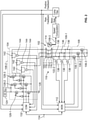
FIG. 2 depicts one particular implementation of the motor control system depicted inFIG. 1 ; and -
FIG. 3 depicts a process flowchart of an example process that may be implemented in the motor control systems ofFIGS. 1 and2 . - The following detailed description is merely exemplary in nature and is not intended to limit the invention or the application and uses of the invention. As used herein, the word "exemplary" means "serving as an example, instance, or illustration." Thus, any embodiment described herein as "exemplary" is not necessarily to be construed as preferred or advantageous over other embodiments. All of the embodiments described herein are exemplary embodiments provided to enable persons skilled in the art to make or use the invention and not to limit the scope of the invention which is defined by the claims. Furthermore, there is no intention to be bound by any expressed or implied theory presented in the preceding technical field, background, brief summary, or the following detailed description.
- Referring now to
FIG. 1 , a functional block diagram of one embodiment of amotor control system 100 is depicted. The depictedsystem 100 includes amulti-phase motor 102, amulti-phase inverter circuit 104, a plurality ofcontrollable switches 106, a plurality of sensors 108, and amonitor circuit 112. Themulti-phase motor 102 includes arotor 114 and a plurality ofstator windings 116. Themotor 102 may be implemented as any one of numerous multi-phase motors, such as a permanent magnet synchronous motor (PMSM), a brushless direct current (BLDC) motor, or as an asynchronous motor, just to name a few. - The
rotor 114 is configured to rotate upon a torque being applied thereto. As is generally known, when thestator windings 116 are energized, a torque is generated and applied to therotor 114. Therotor 114 thus rotates in the direction and speed of the applied torque. Although therotor 114 may be variously configured and implemented, in one particular embodiment, such as the embodiment depicted inFIG. 2 , therotor 114 is implemented as a permanent magnet rotor. - The
multi-phase stator 116 is implemented with a plurality of individual, electrically isolated stator windings, and each stator winding is associated with a different phase. It will be appreciated that thestator 116 may be variously configured and implemented, but in one particular embodiment, such as the one depicted inFIG. 2 , the multi-phase stator includes three individual, electrically isolated stator windings 118 (e.g., 118-1, 118-2, 118-3). Each stator winding 118 includes two terminals 122, a first terminal 122-1 and a second terminal 122-2. It will be appreciated that the stator windings 118 may be configured as three-phase wye windings, as depicted inFIG. 2 , or as three-phase delta windings. - The
multi-phase inverter circuit 104 is coupled to the first terminal 122-1 of each of the stator windings 118. Themulti-phase inverter circuit 104 is responsive to motor command signals to controllably couple the first terminal 112-1 of one or more of the stator windings 118 to either apower source 124 or a circuitcommon node 126, to thereby energize one or more of the stator windings 118. Themulti-phase inverter circuit 104 may be configured as any one of numerous known inverter topologies to implement this functionality. In one particular embodiment, such as the one depicted inFIG. 2 , themulti-phase inverter circuit 104 includes a plurality of series-connected switches 128 and acontroller 132. More specifically, it includes a first pair of series-connected switches 128-1, a second pair of series-connected switches 128-2, and a third pair of series-connected switches 128-3, where the first terminal 112-1 of each stator winding 118 is connected between a different one of the first, second, and third pair of series-connected switches 128. In the embodiment depicted inFIG. 2 , the series-connected switches 128 are each implemented using suitable field effect transistors (FETs), but could also be implemented using any one of numerous other suitable switch devices, now known or developed in the future. - The
controller 132 is coupled to receive motor command signals 134 and feedback signals from one or more of the sensors 108. Thecontroller 132 is configured, in response to themotor command signal 134 and the feedback signals, to command the series-connected switches 128, using any one of numerous know commutation schemes, to controllably couple the first terminal 112-1 of one or more of the stator windings 118 to either thepower source 124 or the circuitcommon node 126. Thecontroller 132 may be implemented using one or more processors and computer-readable storage devices or media encoded with programming instructions for configuring thecontroller 132. The one or more processors may be any custom-made or commercially available processor, a central processing unit (CPU), a graphics processing unit (GPU), an application specific integrated circuit (ASIC), a field programmable gate array (FPGA), a digital signal controller (DSC), an auxiliary processor among several processors associated with the controller, a semiconductor-based microprocessor (in the form of a microchip or chip set), any combination thereof, or generally any device for executing instructions. - The computer readable storage devices or media may include volatile and nonvolatile storage in read-only memory (ROM), random-access memory (RAM), and keep-alive memory (KAM), for example. KAM is a persistent or non-volatile memory that may be used to store various operating variables while the processor is powered down. The computer-readable storage device or media may be implemented using any of a number of known memory devices such as PROMs (programmable read-only memory), EPROMs (electrically PROM), EEPROMs (electrically erasable PROM), flash memory, or any other electric, magnetic, optical, or combination memory devices capable of storing data, some of which represent executable programming instructions, used by the
controller 132. - The
controllable switches 106 are each associated with a different one of the second terminals 122-2, and eachcontrollable switch 106 is electrically coupled in series between its associated second terminal 122-2 and a common winding node 128. In the depicted embodiment, thesystem 100 includes three controllable switches 106-1, 106-2, 106-3, and each is responsive to switch commands to operate in either a first switch mode or a second switch mode. In the first switch mode, eachcontrollable switch 106 electrically couples the second terminal 122-2 of its associated stator winding 118 to the common winding node 128. In the second switch mode, eachcontrollable switch 106 electrically isolates the second terminal 122-2 of its associated stator winding 118 from the common winding node 128. Thecontrollable switches 106 may be implemented using any one of numerous types of switches, including any one of numerous types of manually-actuated switches, any one of numerous types of electromechanical switches (e.g., relays, contactors, etc.), any one of numerous types of solid state semiconductor switches (e.g., MOSFETs, FETs, bipolar transistors, etc.), or various combinations thereof, or any other suitable type of switch now known or developed in the future. - Each of the sensors 108 is configured to sense a motor state variable and supply a sensor signal representative of the sensed motor state variable to at least the
monitor circuit 112. In some instances, one or more of the sensed motor state variables may also be supplied to themulti-phase inverter circuit 104. The plurality of sensors 108 may vary in type, location, and configuration. In one particular embodiment, the sensors 108 include at least a plurality of monitor circuit current sensors 108-1 and a plurality of inverter circuit current sensors 108-2, but may also include a position sensor 108-3 (seeFIG. 2 ), and a speed sensor (not depicted), just to name a few. Each of the current sensors 108-1, 108-2 is configured to sense current flow through a different one of the stator windings 118-1, 118-2, 118-3, and supplies signals representative thereof. As depicted, the monitor current sensors 108-1 supply the signals to themonitor circuit 112, and the inverter current sensors 108-2 supply the signals to themulti-phase inverter circuit 104. The position sensor 108-3, when included, senses the rotational position of therotor 114, and supplies position feedback signals to themulti-phase inverter circuit 104 and themonitor circuit 112. The speed sensor, when included, senses the rotational speed of therotor 114, and supplies speed (or rate) feedback signals to themulti-phase inverter circuit 104 and themonitor circuit 112. In some embodiments, such as the one depicted inFIG. 2 , the speed feedback signal may be derived from the position feedback signal. It will be appreciated that the sensors 108 can be disposed internally or externally to the motor, be implemented as part of themulti-phase inverter circuit 104 and/or themonitor circuit 112, or be implemented as a completely separate circuit, or various combinations thereof. - The current sensors 108-1, 108-2, the speed sensor, and the position sensor may all be implemented using any one of numerous types of suitable sensors, now known or developed in the future. In one particular embodiment, such as the one depicted in
FIG. 2 , each monitor circuit current sensor 108-1 includes aresistor 136 and anoperational amplifier 138. Eachresistor 136 is connected in series between a different one of thecontrollable switches 106 and a different one of the second terminals 122-2. The voltage drop across eachresistor 136, which is directly proportional to the current flow therethrough, and thus the current flow in its respective winding 118, is supplied to the associatedoperational amplifier 138, which supplies a signal representative of the current flow to themonitor circuit 112. Similarly, each inverter circuit current sensor 108-2 includes aresistor 142 and anoperational amplifier 144. Eachresistor 142 is connected in series between a different one of the series-connected switches 128 and a different one of the first terminals 122-1. The voltage drop across eachresistor 142, which is directly proportional to the current flow therethrough, and thus the current flow in its respective winding 118, is supplied to the associatedoperational amplifier 144, which supplies a signal representative of the current flow to themulti-phase inverter circuit 104, and may also, in some embodiments, supply the signals to themonitor circuit 112. - The
monitor circuit 112 is coupled to each of thecontrollable switches 106 and to each of the sensors 108, and also receives the motor commands 134. AsFIG. 1 also depicts, themonitor circuit 112 may also, in some embodiments, be in operable communication with themulti-phase inverter circuit 104. Themonitor circuit 112 is responsive to each of the sensor signals to determine when one or more of the sensed motor state variables attains a predetermined threshold magnitude. For example, themonitor circuit 112 may be configured to determine when the current flow through one or more of the stator windings 118 is too high or too low. Themonitor circuit 112 may also or instead be configured to determine when motor speed is too high or too low, and/or when motor position deviates too much from the commanded motor position. - When none of the sensed motor state variables has attained the predetermined threshold magnitude, the
monitor circuit 112 supplies a switch command each of thecontrollable switches 106 that causes each of thecontrollable switches 106 to operate in the first switch mode, to thereby electrically couple the second terminal 122-2 of its associated stator winding 118 to the common winding node 128. However, when one or more of the sensed motor state variables does attain its predetermined threshold magnitude, themonitor circuit 112 supplies a switch command to one or more of thecontrollable switches 106 that causes the one or morecontrollable switches 106 to operate in the second switch mode, to thereby electrically isolate the second terminal 122-2 of its associated stator winding 118 from the common winding node 128. Themonitor circuit 112 may also, in some embodiments, transmit a signal to themulti-phase inverter circuit 104 indicating which of the one or morecontrollable switches 106 has been commanded to operate in the second switch mode. In response to this signal, themulti-phase inverter circuit 104 can appropriately adjust the control algorithm. In other embodiments, themulti-phase inverter circuit 104 may be configured to automatically adjust the control algorithm without this signal. - The
monitor circuit 112 may be implemented using one or more processors and computer-readable storage devices or media encoded with programming instructions for configuring themonitor circuit 112. The one or more processors may be any custom-made or commercially available processor, a central processing unit (CPU), a graphics processing unit (GPU), an application specific integrated circuit (ASIC), a field programmable gate array (FPGA), a digital signal controller (DSC), an auxiliary processor among several processors associated with the controller, a semiconductor-based microprocessor (in the form of a microchip or chip set), any combination thereof, or generally any device for executing instructions. - The computer readable storage devices or media may include volatile and nonvolatile storage in read-only memory (ROM), random-access memory (RAM), and keep-alive memory (KAM), for example. KAM is a persistent or non-volatile memory that may be used to store various operating variables while the processor is powered down. The computer-readable storage device or media may be implemented using any of a number of known memory devices such as PROMs (programmable read-only memory), EPROMs (electrically PROM), EEPROMs (electrically erasable PROM), flash memory, or any other electric, magnetic, optical, or combination memory devices capable of storing data, some of which represent executable programming instructions, used by the
monitor circuit 112. - The above-described process that is implemented in the
monitor circuit 112 is depicted in flowchart form inFIG. 3 and, for completeness, will now be described. In doing so, it should be noted that the order of operation within theprocess 300 is not limited to the sequential execution as illustrated in the figure, but may be performed in one or more varying orders as applicable and in accordance with the present disclosure. - The
example process 300 includes receiving processing the sensors signals 302, and then determining if one or more of the sensed motor state variables has attained itspredetermined threshold magnitude 304. When none of the sensed motor state variables has attained the predetermined threshold magnitude (e.g., NO at task 304), themonitor circuit 112 commands each of the controllable switches to operate in the first switch mode (306), and the process repeats. However, when one or more of the sensed motor state variables does attain its predetermined threshold magnitude, themonitor circuit 112 commands the appropriatecontrollable switches 106 to operate in the second switch mode (308), and the process repeats. As noted above, in some embodiments themonitor circuit 112 may also transmit a signal to themulti-phase inverter circuit 104 indicating which of the one or morecontrollable switches 106 has been commanded to operate in the second switch mode. - The system and method described herein allows the
motor 102 to be commutated with degraded performance using only two stator windings 118, and does so without increasing system complexity, weight, and size relative to know motor control systems. - Those of skill in the art will appreciate that the various illustrative logical blocks, modules, circuits, and algorithm steps described in connection with the embodiments disclosed herein may be implemented as electronic hardware, computer software, or combinations of both. Some of the embodiments and implementations are described above in terms of functional and/or logical block components (or modules) and various processing steps. However, it should be appreciated that such block components (or modules) may be realized by any number of hardware, software, and/or firmware components configured to perform the specified functions. To clearly illustrate this interchangeability of hardware and software, various illustrative components, blocks, modules, circuits, and steps have been described above generally in terms of their functionality. Whether such functionality is implemented as hardware or software depends upon the particular application and design constraints imposed on the overall system. Skilled artisans may implement the described functionality in varying ways for each particular application, but such implementation decisions should not be interpreted as causing a departure from the scope of the present invention. For example, an embodiment of a system or a component may employ various integrated circuit components, e.g., memory elements, digital signal processing elements, logic elements, look-up tables, or the like, which may carry out a variety of functions under the control of one or more microprocessors or other control devices. In addition, those skilled in the art will appreciate that embodiments described herein are merely exemplary implementations.
- The various illustrative logical blocks, modules, and circuits described in connection with the embodiments disclosed herein may be implemented or performed with a general purpose processor, a digital signal processor (DSP), an application specific integrated circuit (ASIC), a field programmable gate array (FPGA) or other programmable logic device, discrete gate or transistor logic, discrete hardware components, or any combination thereof designed to perform the functions described herein. A general-purpose processor may be a microprocessor, but in the alternative, the processor may be any conventional processor, controller, microcontroller, or state machine. A processor may also be implemented as a combination of computing devices, e.g., a combination of a DSP and a microprocessor, a plurality of microprocessors, one or more microprocessors in conjunction with a DSP core, or any other such configuration.
- The steps of a method or algorithm described in connection with the embodiments disclosed herein may be embodied directly in hardware, in a software module executed by a processor, or in a combination of the two. A software module may reside in RAM memory, flash memory, ROM memory, EPROM memory, EEPROM memory, registers, hard disk, a removable disk, a CD-ROM, or any other form of storage medium known in the art. An exemplary storage medium is coupled to the processor such that the processor can read information from, and write information to, the storage medium. In the alternative, the storage medium may be integral to the processor. The processor and the storage medium may reside in an ASIC.
- Techniques and technologies may be described herein in terms of functional and/or logical block components, and with reference to symbolic representations of operations, processing tasks, and functions that may be performed by various computing components or devices. Such operations, tasks, and functions are sometimes referred to as being computer-executed, computerized, software-implemented, or computer-implemented. In practice, one or more processor devices can carry out the described operations, tasks, and functions by manipulating electrical signals representing data bits at memory locations in the system memory, as well as other processing of signals. The memory locations where data bits are maintained are physical locations that have particular electrical, magnetic, optical, or organic properties corresponding to the data bits. It should be appreciated that the various block components shown in the figures may be realized by any number of hardware, software, and/or firmware components configured to perform the specified functions. For example, an embodiment of a system or a component may employ various integrated circuit components, e.g., memory elements, digital signal processing elements, logic elements, look-up tables, or the like, which may carry out a variety of functions under the control of one or more microprocessors or other control devices.
- When implemented in software or firmware, various elements of the systems described herein are essentially the code segments or instructions that perform the various tasks. The program or code segments can be stored in a processor-readable medium or transmitted by a computer data signal embodied in a carrier wave over a transmission medium or communication path. The "computer-readable medium", "processor-readable medium", or "machine-readable medium" may include any medium that can store or transfer information. Examples of the processor-readable medium include an electronic circuit, a semiconductor memory device, a ROM, a flash memory, an erasable ROM (EROM), a floppy diskette, a CD-ROM, an optical disk, a hard disk, a fiber optic medium, a radio frequency (RF) link, or the like. The computer data signal may include any signal that can propagate over a transmission medium such as electronic network channels, optical fibers, air, electromagnetic paths, or RF links. The code segments may be downloaded via computer networks such as the Internet, an intranet, a LAN, or the like.
- Some of the functional units described in this specification have been referred to as "modules" in order to more particularly emphasize their implementation independence. For example, functionality referred to herein as a module may be implemented wholly, or partially, as a hardware circuit comprising custom VLSI circuits or gate arrays, off-the-shelf semiconductors such as logic chips, transistors, or other discrete components. A module may also be implemented in programmable hardware devices such as field programmable gate arrays, programmable array logic, programmable logic devices, or the like. Modules may also be implemented in software for execution by various types of processors. An identified module of executable code may, for instance, comprise one or more physical or logical modules of computer instructions that may, for instance, be organized as an object, procedure, or function. Nevertheless, the executables of an identified module need not be physically located together, but may comprise disparate instructions stored in different locations that, when joined logically together, comprise the module and achieve the stated purpose for the module. Indeed, a module of executable code may be a single instruction, or many instructions, and may even be distributed over several different code segments, among different programs, and across several memory devices. Similarly, operational data may be embodied in any suitable form and organized within any suitable type of data structure. The operational data may be collected as a single data set, or may be distributed over different locations including over different storage devices, and may exist, at least partially, merely as electronic signals on a system or network.
- In this document, relational terms such as first and second, and the like may be used solely to distinguish one entity or action from another entity or action without necessarily requiring or implying any actual such relationship or order between such entities or actions. Numerical ordinals such as "first," "second," "third," etc. simply denote different singles of a plurality and do not imply any order or sequence unless specifically defined by the claim language. The sequence of the text in any of the claims does not imply that process steps must be performed in a temporal or logical order according to such sequence unless it is specifically defined by the language of the claim. The process steps may be interchanged in any order without departing from the scope of the invention as long as such an interchange does not contradict the claim language and is not logically nonsensical.
- Furthermore, depending on the context, words such as "connect" or "coupled to" used in describing a relationship between different elements do not imply that a direct physical connection must be made between these elements. For example, two elements may be connected to each other physically, electronically, logically, or in any other manner, through one or more additional elements.
- While at least one exemplary embodiment has been presented in the foregoing detailed description of the invention, it should be appreciated that a vast number of variations exist. It should also be appreciated that the exemplary embodiment or exemplary embodiments are only examples, and are not intended to limit the scope, applicability, or configuration of the invention in any way. Rather, the foregoing detailed description will provide those skilled in the art with a convenient road map for implementing an exemplary embodiment of the invention. It being understood that various changes may be made in the function and arrangement of elements described in an exemplary embodiment without departing from the scope of the invention as set forth in the appended claims.
Claims (11)
- A motor control system, comprising:a multi-phase motor including a rotor and a plurality of stator windings, each stator winding associated with a different phase, each stator winding including a first terminal and a second terminal;a multi-phase inverter circuit coupled to the first terminal of each of the stator windings, the multi-phase inverter circuit responsive to motor command signals to controllably couple the first terminal of one or more of the stator windings to either a power source or a circuit common node;a plurality of controllable switches, each controllable switch associated with a different one of the second terminals, each controllable switch electrically coupled in series between its associated second terminal and a common winding node, each controllable switch responsive to switch commands to operate in either a first switch mode, in which each controllable switch electrically couples the second terminal of its associated stator winding to the common winding node, or a second switch mode, in which each controllable switch electrically isolates the second terminal of its associated stator winding from the common winding node;a plurality of sensors, each sensor configured to sense a motor state variable and supply a sensor signal representative of the sensed motor state variable; anda monitor circuit coupled to each of the controllable switches and to each of the sensors, the monitor circuit responsive to each of the sensor signals to:determine when one or more of the sensed motor state variables attains a predetermined threshold magnitude, andwhen one or more of the sensed motor state variables attains the predetermined threshold magnitude, to supply a switch command to one or more of the controllable switches that causes the one or more controllable switches to operate in the second switch mode.
- The motor control system of claim 1, wherein:
when none of the sensed motor state variables has attained the predetermined threshold magnitude, the monitor circuit supplies a switch command each of the controllable switches that causes each of the controllable switches to operate in the first switch mode. - The motor control system of claim 1, wherein the inverter circuit comprises:a first pair of series-connected switches;a second pair of series-connected switches; anda third pair of series-connected switches.
- The motor control system of claim 3, wherein the first terminal of each stator winding is connected between a different one of the first, second, and third pair of series-connected switches.
- The motor control system of claim 1, wherein the plurality of sensors includes one or more of a plurality of current sensors, a speed sensor, and a position sensor.
- The motor control system of claim 5, wherein:the plurality of sensors includes a plurality of current sensors;each current sensor includes a resistor and an operational amplifier;each resistor is connected in series between a different one of the controllable switches and a different one of the second terminals.
- The motor control system of claim 1, wherein the multi-phase motor is a permanent magnet synchronous motor.
- The motor control system of claim 1, wherein the multi-phase motor is a brushless DC motor.
- The motor control system of claim 1, wherein the multi-phase motor is an asynchronous motor.
- The motor control system of claim 1, wherein the plurality of stator windings are configured as three-phase wye windings.
- The motor control system of claim 1, wherein the plurality of stator windings are configured as three-phase delta windings.
Applications Claiming Priority (1)
| Application Number | Priority Date | Filing Date | Title |
|---|---|---|---|
| US17/004,865 US11183960B1 (en) | 2020-08-27 | 2020-08-27 | Fail-safe motor control architecture for open-end winding motors |
Publications (2)
| Publication Number | Publication Date |
|---|---|
| EP3961913A1 true EP3961913A1 (en) | 2022-03-02 |
| EP3961913B1 EP3961913B1 (en) | 2025-03-12 |
Family
ID=77274684
Family Applications (1)
| Application Number | Title | Priority Date | Filing Date |
|---|---|---|---|
| EP21190453.7A Active EP3961913B1 (en) | 2020-08-27 | 2021-08-09 | Fail-safe motor control architecture for open-end winding motors |
Country Status (2)
| Country | Link |
|---|---|
| US (1) | US11183960B1 (en) |
| EP (1) | EP3961913B1 (en) |
Citations (2)
| Publication number | Priority date | Publication date | Assignee | Title |
|---|---|---|---|---|
| US20200021233A1 (en) * | 2017-03-23 | 2020-01-16 | Hitachi Automotive Systems, Ltd. | Motor system |
| WO2020090279A1 (en) * | 2018-11-02 | 2020-05-07 | 日立オートモティブシステムズ株式会社 | Drive system and control method |
Family Cites Families (9)
| Publication number | Priority date | Publication date | Assignee | Title |
|---|---|---|---|---|
| BR0209188A (en) | 2001-04-26 | 2004-08-03 | Borealis Tech Ltd | Changeable Spiral Mesh Connected Electric Rotary Machine |
| JP4065441B2 (en) * | 2004-07-28 | 2008-03-26 | 松下電器産業株式会社 | Motor driving apparatus and motor driving method |
| JP2006149153A (en) | 2004-11-24 | 2006-06-08 | Mitsubishi Electric Corp | Motor control device |
| JP5175569B2 (en) * | 2008-02-07 | 2013-04-03 | ルネサスエレクトロニクス株式会社 | Synchronous motor drive system |
| US9291678B2 (en) | 2012-05-31 | 2016-03-22 | Deere & Company | Method and controller for an electric motor with switch testing |
| JP5569606B1 (en) * | 2013-02-01 | 2014-08-13 | 株式会社安川電機 | Inverter device and electric motor drive system |
| US9543879B2 (en) * | 2014-03-24 | 2017-01-10 | Chevron U.S.A. Inc. | System and method for controlling muliphase electric motors |
| JP6469596B2 (en) | 2016-01-13 | 2019-02-13 | 日立オートモティブシステムズ株式会社 | In-vehicle control device |
| US11088642B2 (en) * | 2019-11-17 | 2021-08-10 | Scnewton Inc. | Electric winding exchanger system |
-
2020
- 2020-08-27 US US17/004,865 patent/US11183960B1/en active Active
-
2021
- 2021-08-09 EP EP21190453.7A patent/EP3961913B1/en active Active
Patent Citations (2)
| Publication number | Priority date | Publication date | Assignee | Title |
|---|---|---|---|---|
| US20200021233A1 (en) * | 2017-03-23 | 2020-01-16 | Hitachi Automotive Systems, Ltd. | Motor system |
| WO2020090279A1 (en) * | 2018-11-02 | 2020-05-07 | 日立オートモティブシステムズ株式会社 | Drive system and control method |
Also Published As
| Publication number | Publication date |
|---|---|
| US11183960B1 (en) | 2021-11-23 |
| EP3961913B1 (en) | 2025-03-12 |
Similar Documents
| Publication | Publication Date | Title |
|---|---|---|
| JP6979767B2 (en) | Motor drive and electric power steering | |
| US8084972B2 (en) | Dual lane control of a permanent magnet brushless motor using non-trapezoidal commutation control | |
| CN110460254B (en) | Control circuit for power converter | |
| EP3865356A1 (en) | Electric braking device for vehicle and control method thereby | |
| JP6302727B2 (en) | Electric motor control device | |
| US10088531B2 (en) | Failure diagnosis device and failure diagnosis method for inverter | |
| US20170166248A1 (en) | Electric power steering device | |
| CN108778896A (en) | Motor control system and electric power steering device equipped with the motor control system | |
| CN110463026A (en) | Electric power steering | |
| EP0920119A1 (en) | Dynamic braking system for electric motors | |
| US10135380B2 (en) | AC rotary machine control apparatus | |
| KR20180090430A (en) | Motor and apparatus for driving motor | |
| EP3709503B1 (en) | Controller for motor | |
| JP6967470B2 (en) | Control device | |
| CN106068611A (en) | Band brake motor | |
| EP3961913B1 (en) | Fail-safe motor control architecture for open-end winding motors | |
| JP7001895B2 (en) | Power converter control circuit | |
| JP6758460B1 (en) | Rotating electric device and electric power steering device | |
| WO2021016183A1 (en) | Fault tolerant operations of a six-phase machine | |
| CN113692702B (en) | Method for monitoring the operation of a frequency converter and frequency converter | |
| US20220077809A1 (en) | Control device for motor | |
| JP2017163748A (en) | Motor control device | |
| US11509250B2 (en) | Control device | |
| JP7182641B2 (en) | Drive system and control method | |
| US20200295698A1 (en) | Controller for motor |
Legal Events
| Date | Code | Title | Description |
|---|---|---|---|
| PUAI | Public reference made under article 153(3) epc to a published international application that has entered the european phase |
Free format text: ORIGINAL CODE: 0009012 |
|
| STAA | Information on the status of an ep patent application or granted ep patent |
Free format text: STATUS: THE APPLICATION HAS BEEN PUBLISHED |
|
| AK | Designated contracting states |
Kind code of ref document: A1 Designated state(s): AL AT BE BG CH CY CZ DE DK EE ES FI FR GB GR HR HU IE IS IT LI LT LU LV MC MK MT NL NO PL PT RO RS SE SI SK SM TR |
|
| RAP3 | Party data changed (applicant data changed or rights of an application transferred) |
Owner name: HONEYWELL INTERNATIONAL INC. |
|
| STAA | Information on the status of an ep patent application or granted ep patent |
Free format text: STATUS: REQUEST FOR EXAMINATION WAS MADE |
|
| 17P | Request for examination filed |
Effective date: 20220902 |
|
| RBV | Designated contracting states (corrected) |
Designated state(s): AL AT BE BG CH CY CZ DE DK EE ES FI FR GB GR HR HU IE IS IT LI LT LU LV MC MK MT NL NO PL PT RO RS SE SI SK SM TR |
|
| P01 | Opt-out of the competence of the unified patent court (upc) registered |
Effective date: 20230421 |
|
| STAA | Information on the status of an ep patent application or granted ep patent |
Free format text: STATUS: EXAMINATION IS IN PROGRESS |
|
| 17Q | First examination report despatched |
Effective date: 20240628 |
|
| GRAP | Despatch of communication of intention to grant a patent |
Free format text: ORIGINAL CODE: EPIDOSNIGR1 |
|
| STAA | Information on the status of an ep patent application or granted ep patent |
Free format text: STATUS: GRANT OF PATENT IS INTENDED |
|
| INTG | Intention to grant announced |
Effective date: 20241018 |
|
| GRAS | Grant fee paid |
Free format text: ORIGINAL CODE: EPIDOSNIGR3 |
|
| GRAA | (expected) grant |
Free format text: ORIGINAL CODE: 0009210 |
|
| STAA | Information on the status of an ep patent application or granted ep patent |
Free format text: STATUS: THE PATENT HAS BEEN GRANTED |
|
| AK | Designated contracting states |
Kind code of ref document: B1 Designated state(s): AL AT BE BG CH CY CZ DE DK EE ES FI FR GB GR HR HU IE IS IT LI LT LU LV MC MK MT NL NO PL PT RO RS SE SI SK SM TR |
|
| REG | Reference to a national code |
Ref country code: GB Ref legal event code: FG4D |
|
| REG | Reference to a national code |
Ref country code: CH Ref legal event code: EP |
|
| REG | Reference to a national code |
Ref country code: DE Ref legal event code: R096 Ref document number: 602021027415 Country of ref document: DE |
|
| REG | Reference to a national code |
Ref country code: IE Ref legal event code: FG4D |
|
| PG25 | Lapsed in a contracting state [announced via postgrant information from national office to epo] |
Ref country code: RS Free format text: LAPSE BECAUSE OF FAILURE TO SUBMIT A TRANSLATION OF THE DESCRIPTION OR TO PAY THE FEE WITHIN THE PRESCRIBED TIME-LIMIT Effective date: 20250612 |
|
| PG25 | Lapsed in a contracting state [announced via postgrant information from national office to epo] |
Ref country code: FI Free format text: LAPSE BECAUSE OF FAILURE TO SUBMIT A TRANSLATION OF THE DESCRIPTION OR TO PAY THE FEE WITHIN THE PRESCRIBED TIME-LIMIT Effective date: 20250312 |
|
| PG25 | Lapsed in a contracting state [announced via postgrant information from national office to epo] |
Ref country code: ES Free format text: LAPSE BECAUSE OF FAILURE TO SUBMIT A TRANSLATION OF THE DESCRIPTION OR TO PAY THE FEE WITHIN THE PRESCRIBED TIME-LIMIT Effective date: 20250312 |
|
| REG | Reference to a national code |
Ref country code: LT Ref legal event code: MG9D |
|
| PG25 | Lapsed in a contracting state [announced via postgrant information from national office to epo] |
Ref country code: NO Free format text: LAPSE BECAUSE OF FAILURE TO SUBMIT A TRANSLATION OF THE DESCRIPTION OR TO PAY THE FEE WITHIN THE PRESCRIBED TIME-LIMIT Effective date: 20250612 |
|
| PG25 | Lapsed in a contracting state [announced via postgrant information from national office to epo] |
Ref country code: HR Free format text: LAPSE BECAUSE OF FAILURE TO SUBMIT A TRANSLATION OF THE DESCRIPTION OR TO PAY THE FEE WITHIN THE PRESCRIBED TIME-LIMIT Effective date: 20250312 |
|
| REG | Reference to a national code |
Ref country code: NL Ref legal event code: MP Effective date: 20250312 |
|
| PG25 | Lapsed in a contracting state [announced via postgrant information from national office to epo] |
Ref country code: LV Free format text: LAPSE BECAUSE OF FAILURE TO SUBMIT A TRANSLATION OF THE DESCRIPTION OR TO PAY THE FEE WITHIN THE PRESCRIBED TIME-LIMIT Effective date: 20250312 |
|
| PG25 | Lapsed in a contracting state [announced via postgrant information from national office to epo] |
Ref country code: GR Free format text: LAPSE BECAUSE OF FAILURE TO SUBMIT A TRANSLATION OF THE DESCRIPTION OR TO PAY THE FEE WITHIN THE PRESCRIBED TIME-LIMIT Effective date: 20250613 Ref country code: BG Free format text: LAPSE BECAUSE OF FAILURE TO SUBMIT A TRANSLATION OF THE DESCRIPTION OR TO PAY THE FEE WITHIN THE PRESCRIBED TIME-LIMIT Effective date: 20250312 |
|
| REG | Reference to a national code |
Ref country code: AT Ref legal event code: MK05 Ref document number: 1775881 Country of ref document: AT Kind code of ref document: T Effective date: 20250312 |
|
| PG25 | Lapsed in a contracting state [announced via postgrant information from national office to epo] |
Ref country code: NL Free format text: LAPSE BECAUSE OF FAILURE TO SUBMIT A TRANSLATION OF THE DESCRIPTION OR TO PAY THE FEE WITHIN THE PRESCRIBED TIME-LIMIT Effective date: 20250312 |
|
| PG25 | Lapsed in a contracting state [announced via postgrant information from national office to epo] |
Ref country code: SE Free format text: LAPSE BECAUSE OF FAILURE TO SUBMIT A TRANSLATION OF THE DESCRIPTION OR TO PAY THE FEE WITHIN THE PRESCRIBED TIME-LIMIT Effective date: 20250312 |
|
| PG25 | Lapsed in a contracting state [announced via postgrant information from national office to epo] |
Ref country code: SM Free format text: LAPSE BECAUSE OF FAILURE TO SUBMIT A TRANSLATION OF THE DESCRIPTION OR TO PAY THE FEE WITHIN THE PRESCRIBED TIME-LIMIT Effective date: 20250312 |
|
| PG25 | Lapsed in a contracting state [announced via postgrant information from national office to epo] |
Ref country code: PT Free format text: LAPSE BECAUSE OF FAILURE TO SUBMIT A TRANSLATION OF THE DESCRIPTION OR TO PAY THE FEE WITHIN THE PRESCRIBED TIME-LIMIT Effective date: 20250714 |
|
| PGFP | Annual fee paid to national office [announced via postgrant information from national office to epo] |
Ref country code: DE Payment date: 20250827 Year of fee payment: 5 |
|
| PG25 | Lapsed in a contracting state [announced via postgrant information from national office to epo] |
Ref country code: IT Free format text: LAPSE BECAUSE OF FAILURE TO SUBMIT A TRANSLATION OF THE DESCRIPTION OR TO PAY THE FEE WITHIN THE PRESCRIBED TIME-LIMIT Effective date: 20250312 Ref country code: PL Free format text: LAPSE BECAUSE OF FAILURE TO SUBMIT A TRANSLATION OF THE DESCRIPTION OR TO PAY THE FEE WITHIN THE PRESCRIBED TIME-LIMIT Effective date: 20250312 |
|
| PGFP | Annual fee paid to national office [announced via postgrant information from national office to epo] |
Ref country code: GB Payment date: 20250826 Year of fee payment: 5 |
|
| PG25 | Lapsed in a contracting state [announced via postgrant information from national office to epo] |
Ref country code: AT Free format text: LAPSE BECAUSE OF FAILURE TO SUBMIT A TRANSLATION OF THE DESCRIPTION OR TO PAY THE FEE WITHIN THE PRESCRIBED TIME-LIMIT Effective date: 20250312 |
|
| PGFP | Annual fee paid to national office [announced via postgrant information from national office to epo] |
Ref country code: FR Payment date: 20250825 Year of fee payment: 5 |
|
| PG25 | Lapsed in a contracting state [announced via postgrant information from national office to epo] |
Ref country code: CZ Free format text: LAPSE BECAUSE OF FAILURE TO SUBMIT A TRANSLATION OF THE DESCRIPTION OR TO PAY THE FEE WITHIN THE PRESCRIBED TIME-LIMIT Effective date: 20250312 Ref country code: EE Free format text: LAPSE BECAUSE OF FAILURE TO SUBMIT A TRANSLATION OF THE DESCRIPTION OR TO PAY THE FEE WITHIN THE PRESCRIBED TIME-LIMIT Effective date: 20250312 |
|
| PG25 | Lapsed in a contracting state [announced via postgrant information from national office to epo] |
Ref country code: RO Free format text: LAPSE BECAUSE OF FAILURE TO SUBMIT A TRANSLATION OF THE DESCRIPTION OR TO PAY THE FEE WITHIN THE PRESCRIBED TIME-LIMIT Effective date: 20250312 |
|
| PG25 | Lapsed in a contracting state [announced via postgrant information from national office to epo] |
Ref country code: SK Free format text: LAPSE BECAUSE OF FAILURE TO SUBMIT A TRANSLATION OF THE DESCRIPTION OR TO PAY THE FEE WITHIN THE PRESCRIBED TIME-LIMIT Effective date: 20250312 |
|
| PG25 | Lapsed in a contracting state [announced via postgrant information from national office to epo] |
Ref country code: IS Free format text: LAPSE BECAUSE OF FAILURE TO SUBMIT A TRANSLATION OF THE DESCRIPTION OR TO PAY THE FEE WITHIN THE PRESCRIBED TIME-LIMIT Effective date: 20250712 |
|
| REG | Reference to a national code |
Ref country code: DE Ref legal event code: R097 Ref document number: 602021027415 Country of ref document: DE |
|
| PG25 | Lapsed in a contracting state [announced via postgrant information from national office to epo] |
Ref country code: DK Free format text: LAPSE BECAUSE OF FAILURE TO SUBMIT A TRANSLATION OF THE DESCRIPTION OR TO PAY THE FEE WITHIN THE PRESCRIBED TIME-LIMIT Effective date: 20250312 |
|
| PLBE | No opposition filed within time limit |
Free format text: ORIGINAL CODE: 0009261 |
|
| STAA | Information on the status of an ep patent application or granted ep patent |
Free format text: STATUS: NO OPPOSITION FILED WITHIN TIME LIMIT |
|
| REG | Reference to a national code |
Ref country code: CH Ref legal event code: L10 Free format text: ST27 STATUS EVENT CODE: U-0-0-L10-L00 (AS PROVIDED BY THE NATIONAL OFFICE) Effective date: 20260121 |
|
| 26N | No opposition filed |
Effective date: 20251215 |
|
| REG | Reference to a national code |
Ref country code: CH Ref legal event code: H13 Free format text: ST27 STATUS EVENT CODE: U-0-0-H10-H13 (AS PROVIDED BY THE NATIONAL OFFICE) Effective date: 20260324 |
|
| PG25 | Lapsed in a contracting state [announced via postgrant information from national office to epo] |
Ref country code: MC Free format text: LAPSE BECAUSE OF FAILURE TO SUBMIT A TRANSLATION OF THE DESCRIPTION OR TO PAY THE FEE WITHIN THE PRESCRIBED TIME-LIMIT Effective date: 20250312 |
|
| PG25 | Lapsed in a contracting state [announced via postgrant information from national office to epo] |
Ref country code: LU Free format text: LAPSE BECAUSE OF NON-PAYMENT OF DUE FEES Effective date: 20250809 |
|
| PG25 | Lapsed in a contracting state [announced via postgrant information from national office to epo] |
Ref country code: CH Free format text: LAPSE BECAUSE OF NON-PAYMENT OF DUE FEES Effective date: 20250831 |