EP3961885A1 - Bus bar module - Google Patents
Bus bar module Download PDFInfo
- Publication number
- EP3961885A1 EP3961885A1 EP19926427.6A EP19926427A EP3961885A1 EP 3961885 A1 EP3961885 A1 EP 3961885A1 EP 19926427 A EP19926427 A EP 19926427A EP 3961885 A1 EP3961885 A1 EP 3961885A1
- Authority
- EP
- European Patent Office
- Prior art keywords
- bus bar
- hole
- spacer
- bus
- bar module
- Prior art date
- Legal status (The legal status is an assumption and is not a legal conclusion. Google has not performed a legal analysis and makes no representation as to the accuracy of the status listed.)
- Withdrawn
Links
Images






Classifications
-
- H—ELECTRICITY
- H02—GENERATION; CONVERSION OR DISTRIBUTION OF ELECTRIC POWER
- H02M—APPARATUS FOR CONVERSION BETWEEN AC AND AC, BETWEEN AC AND DC, OR BETWEEN DC AND DC, AND FOR USE WITH MAINS OR SIMILAR POWER SUPPLY SYSTEMS; CONVERSION OF DC OR AC INPUT POWER INTO SURGE OUTPUT POWER; CONTROL OR REGULATION THEREOF
- H02M3/00—Conversion of DC power input into DC power output
- H02M3/003—Constructional details, e.g. physical layout, assembly, wiring or busbar connections
-
- H—ELECTRICITY
- H02—GENERATION; CONVERSION OR DISTRIBUTION OF ELECTRIC POWER
- H02G—INSTALLATION OF ELECTRIC CABLES OR LINES, OR OF COMBINED OPTICAL AND ELECTRIC CABLES OR LINES
- H02G5/00—Installations of bus-bars
- H02G5/005—Laminated bus-bars
-
- H—ELECTRICITY
- H02—GENERATION; CONVERSION OR DISTRIBUTION OF ELECTRIC POWER
- H02M—APPARATUS FOR CONVERSION BETWEEN AC AND AC, BETWEEN AC AND DC, OR BETWEEN DC AND DC, AND FOR USE WITH MAINS OR SIMILAR POWER SUPPLY SYSTEMS; CONVERSION OF DC OR AC INPUT POWER INTO SURGE OUTPUT POWER; CONTROL OR REGULATION THEREOF
- H02M7/00—Conversion of AC power input into DC power output; Conversion of DC power input into AC power output
- H02M7/003—Constructional details, e.g. physical layout, assembly, wiring or busbar connections
Definitions
- the present application relates to a bus bar module.
- Patent Document 1 In hybrid vehicles and electric vehicles, power conversion devices are employed which perform power conversion using semiconductor modules.
- a power conversion device in Patent Document 1, an example is disclosed which is provided with multiple semiconductor modules for converting power and a bus bar module that is electrically connected to the power terminals of the respective semiconductor modules.
- the bus bar module has multiple bus bars each made of a conductor.
- the multiple bus bars are electrically connected, at their respective one end portions, to the power terminals of the respective semiconductor modules. Further, the other end portions of the bus bars are electrically connected to the respective phase terminals of a motor.
- the bus bars are each formed into a rectangular and flat-shaped cross section, and form parallel plates.
- a semiconductor switching element which serves as a power switch for turning ON/OFF a high voltage and a large amount of current.
- the potential at each of the bus bars is the same as the potential at the output terminal of each of the semiconductor modules, so that a potential difference corresponding to an AC or DC high voltage may be generated between the respective bus bars. Thus, it is necessary to ensure insulation between the bus bars.
- Patent Document 1 a structure is disclosed in which the multiple bus bars are encapsulated with an encapsulation resin having an insulation property, so that they are formed into a bus bar module.
- the power conversion device for in-vehicle use is required to be made compact since its mountable region inside the vehicle is restricted. Accordingly, it is also necessary to ensure insulation against its surrounding components other than bus bar, such as a control board, a capacitor, a cooler, etc. Thus, it is effective to encapsulate the multiple bus bars entirely with the insulating encapsulation resin.
- insert molding using the insulating resin may be employed. The insert molding is advantageous in productivity.
- a high-speed switching element for example, an IGBT (Insulated Gate Bipolar Transistor), a MOSFET (metal-oxide-semiconductor field-effect transistor) or the like is used as a semiconductor element incorporated in the semiconductor module, it is required to reduce interconnection inductance as much as possible to thereby reduce the change rate of a current flowing through the semiconductor switching element.
- IGBT Insulated Gate Bipolar Transistor
- MOSFET metal-oxide-semiconductor field-effect transistor
- the insulating spacers sandwiched between bus bars is located so as to entirely cover the parallel planar regions, and the bus bars and the spacers, other than the terminal portions of the bus bars, are entirely covered with the encapsulation resin made of an insulating material; however, although the bus bar and the spacer are in contact with each other, they are not adhered to each other. Accordingly, the contact faces of the bus bar and the spacer are not adhered to each other, while they are both adhered to the encapsulation resin because of being entirely encapsulated with the resin through insert molding or the like.
- This application discloses a technique for solving a problem as described above, and an object thereof is to suppress deterioration in the insulation property of the spacer by reducing stresses imposed thereon, to thereby provide a bus bar module which is highly reliable in insulation performance.
- a bus bar module disclosed in this application is characterized by comprising: a first bus bar having a first hole in a planar region thereof and made of an electrically conductive material; a second bus bar opposed to the first bus bar, having a second hole in a planar region thereof and at a position corresponding to the first hole, and made of an electrically conductive material; a spacer made of an insulating material, which is sandwiched between the first bus bar and the second bus bar, and in which a third hole is provided so as to overlap with the first hole and the second hole, and a resin mold covering the first bus bar, the second bus bar and the spacer; wherein a through-hole that is established by the first hole, the second hole and the third hole, is filled with a portion of the resin mold.
- Fig.1 is a set of plan views each showing a configuration of a bus bar module according to Embodiment 1, in which Fig.1 (a) shows the view after resin-encapsulation and Fig.1(b) shows the view before resin-encapsulation.
- Fig.2 is a sectional view along arrow AA in Fig.1(a) .
- a bus bar module 101 is configured mainly with: a bus bar 1a as a first bus bar and a bus bar 1b as a second bus bar, which are opposed to each other and each made of an electrically conductive material; a spacer 2 which is sandwiched between the bus bars 1a, 1b and made of an insulating material; and a resin mold 3 formed of an encapsulation resin made of an insulating material that entirely covers the bus bars 1a, 1b and the spacer 2, other than terminal portions 11a, 11b of the bus bars 1a, 1b.
- the bus bars 1a, 1b are provided as a positive electrode and a negative electrode so as to be opposed to each other, and in order to ensure insulation between the bus bar 1a and the bus bar 1b, the spacer 2 is sandwiched therebetween so as to entirely cover their respective parallel planar regions 11c, 11d.
- a hole 20a as a first hole and a hole 20b as a second hole, that are mutually corresponding holes, are created, respectively.
- a material of each of the bus bars 1a, 1b usually, Cu, a Cu alloy or the like, that is excellent in electric conductivity and thermal conductivity, is used. Note that, other than this, Al or an Al alloy may be used.
- the spacer 2 is provided so as to entirely cover the parallel planar regions 11c, 11d of the bus bar 1a and the bus bar 1b.
- a hole 20h as a third hole is created so as to overlap with the holes 20a, 20b provided in the parallel planar regions 11c, 11d of the bus bars 1a, 1b.
- PPS Poly Phenylene Sulfide
- the spacer 2 made of PPS it is favorable if its thickness is not less than 1 mm, from the viewpoints of structural strength and insulation property. Furthermore, in order to decrease the mutual inductance between bus bar 1a and the bus bar 1b, it is appropriate if the thickness of the spacer 2 is not more than 1.5 mm.
- an insulating resin such as PBT (Poly Butylene Terephthalate) or the like, may be used. Further, a thermally-conductive insulating sheet having a high thermal conductivity may instead be used.
- the resin mold 3 is formed in such a manner that the bus bar 1a and the bus bar 1b with the spacer 2 sandwiched therebetween, other than the terminal portions 11a, 11b, are entirely covered with the encapsulation resin made of an insulating material, and a through-hole 20H established by the holes 20a, 20b of the respective bus bars 1a, 1b and the hole 20h of the spacer 2 is filled also with that resin.
- PPS is used for the resin mold 3 from the viewpoints of structural strength, thermal tolerance, insulation property and productivity.
- an insulating resin used for insert molding such as PBT or the like, may be used.
- a feature of this application resides in that the through-hole 20H established by the holes 20a, 20b of the bus bars 1a, 1b and the hole 20h of the spacer 2 is filled with a portion of the resin mold 3, to thereby adhere each of the bus bar 1a, the bus bar 1b and the spacer 2 to the resin mold 3 even in the through-hole 20H.
- the length of each of non-adhered regions between the bus bars 1a, 1b and the spacer 2 along the parallel planar regions 11c, 11d is decreased while keeping the areas of the parallel planar regions 11c, 11d large. This makes it possible to reduce the amount of warpage to thereby suppress the stress concentration, and thus to suppress occurrence of cracking to thereby achieve improvement in the insulation performance. Further, because their fixed position is established, there is also provided an effect that the quake resistance is improved.
- the through-hole 20H is positioned in the central portions of the parallel planar regions 11c, 11d; however, this is not limitative, and it only has to be placed in the parallel planar regions 11c, 11d of the bus bars 1a, 1b.
- Fig.3 is a set of sectional views showing a manufacturing method of the bus bar module 101 according to Embodiment 1.
- the spacer 2 is placed on the bus bar 1a.
- the positions of the bus bar 1a and the spacer 2 are determined so that the respective central axes of the hole 20a of the bus bar 1a and the hole 20h of the spacer 2 coincide with each other.
- the bus bar 1b is placed on the spacer 2.
- the positions of the bus bar 1b and the spacer 2 are determined so that the respective central axes of the hole 20b of the bus bar 1b and the hole 20h of the spacer 2 coincide with each other.
- the through-hole 20H is established.
- insert molding is carried out by inserting the bus bars 1a, 1b with the spacer 2 sandwiched therebetween, into an unshown mold, and filling a region around the bus bars 1a, 1b with an encapsulation resin 30.
- the encapsulation resin 30 is also filled in the through-hole 20H established by the holes 20a, 20b of the bus bars 1a, 1b and the hole 20h of the spacer 2.
- the thus-filled encapsulation resin 30 is cured by heating, so that the resin mold 3 is formed which covers the bus bars 1a, 1b with the spacer 2 sandwiched therebetween and a portion of which fills up the through-hole 20H, to thereby provide the bus bar module 101.
- bus bar module 101 although the spacer 2 is in contact with each of the bus bars 1a, 1b, they are not adhered to each other.
- the resin mold 3 is adhered to each of the bus bar 1a, the bus bar 1b and the spacer 2. This is because the bus bar 1a, the bus bar 1b and the spacer 2 is insert-molded in the resin mold 3.
- the bus bars 1a, 1b with the spacer 2 sandwiched therebetween are covered with the encapsulation resin 30 and the through-hole 20H established by the holes 20a, 20b of the bus bars 1a, 1b and the hole 20h of the spacer 2 is filled with the encapsulation resin 30, and then the resin mold 3 is formed by heat-curing, so that each of the bus bar 1a, the bus bar 1b and the spacer 2 is adhered to the resin mold 3 even in the through-hole 20H.
- the length of each of non-adhered regions between the bus bars 1a, 1b and the spacer 2 along the parallel planar regions 11c, 11d is decreased while keeping the areas of the parallel planar regions 11c, 11d large. This makes it possible to reduce the amount of warpage to thereby suppress the stress concentration, and thus to suppress occurrence of cracking to thereby achieve improvement in the insulation performance. Further, because the fixed position is established, there is also provided an effect that the quake resistance is improved.
- the bus bar module 101 comprises: the bus bar 1a having the hole 20a in the parallel planar region 11c and made of an electrically conductive material; the bus bar 1b opposed to the bus bar 1a, having the hole 20b in the parallel planar region 11d and at a position corresponding to the hole 20a, and made of an electrically conductive material; the spacer 2 made of an insulating material, which is sandwiched between the bus bar 1a and the bus bar 1b, and in which the hole 20h is provided so as to overlap with the hole 20a and the hole 20b; and the resin mold 3 covering the bus bars 1a, 1b and the spacer 2; wherein the through-hole 20H that is established by the hole 20a, the hole 20b and the hole 20h, is filled with a portion of the resin mold 3.
- the length of each of non-adhered regions between the bus bars and the spacer along the respective parallel planar regions is decreased while keeping the areas of the parallel planar regions large. This makes it possible to reduce the amount of warpage to thereby suppress the stress concentration, and thus to suppress occurrence of cracking to thereby achieve improvement in the insulation performance.
- the fixed position is established, there is also provided an effect that the quake resistance is improved. Furthermore, when the thickness of the bus bar 1a and the thickness of the bus bar 1b are equal to each other, and the thickness of a portion of the resin mold 3 located on the bus bar 1a and the thickness of a portion of the resin mold 3 located on the bus bar 1b are equal to each other, it is possible to suppress unbalance leading to warpage from occurring in the vertical direction. This is effective in making it possible to further mitigate stress concentration on the spacer.
- Embodiment 1 a case has been described where the positions of the bus bars 1a, 1b and the spacer 2 are determined so that the central axes of the hole 20a, the hole 20b and the hole 20h coincide with each other, whereas in Embodiment 2, a case will be described where a protrusion portion is provided at a circumferential edge portion of the spacer around the hole thereof.
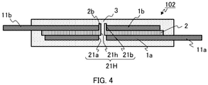
- Fig.4 is a sectional view showing a configuration of a bus bar module according to Embodiment 2. As shown in Fig.4 , in a bus bar module 102, at a circumferential edge portion of the spacer 2 around a hole 21h being located on a side nearer to the bus bar 1b, a protrusion portion 2b as a first protrusion portion is provided so as to cover the inner wall of a hole 21b of the bus bar 1b.
- the protrusion portion 2b of the spacer 2 is formed to be insertable into the hole 21b of the bus bar 1b, so that, at the time of placing the bus bar 1b on the spacer 2, their positions can easily be determined merely by insertion of the protrusion portion 2b into the hole 20b, without depending on a placing operation to be performed so that the central axes of the hole 20b and the hole 21h coincide with each other.
- bus bar module 102 The other configuration and manufacturing method of the bus bar module 102 according to Embodiment 2 are the same as those of the bus bar module 101 of Embodiment 1. Thus, the same reference numerals are given to the equivalent parts, so that description thereof will be omitted.
- the protrusion portion 2b is provided at its circumferential edge portion around the hole 21h being located on a side nearer to the bus bar 1b, so as to cover the hole 21b.
- the positions can easily be determined merely by insertion of the protrusion portion into the hole of the bus bar, without depending on a placing operation to be performed so that the central axes of the hole of the bus bar and the hole of the spacer coincide with each other.
- the protrusion portion 2b is provided at the circumferential edge portion of the spacer 2 around the hole 21h being located on a side nearer to the bus bar 1b; however, this is not limitative.
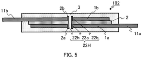
- a protrusion portion 2a as a second protrusion portion may be provided at a circumferential edge portion of the spacer 2 around the hole 21h being located on a side nearer to the bus bar 1a, so as to cover the hole 21a, and as shown in Fig.5 , the protrusion portions 2a, 2b may be provided at both the circumferential edge portions of the spacer 2 around the hole 22h that are located on a side nearer to the bus bar 1a and on a side nearer to the bus bar 1b, so as to cover the holes 22a, 22b, respectively. Even in this case, it is possible to achieve an effect that is similar to the effect according to Embodiment 2.
- the protrusion portions 2a, 2b are provided at both the circumferential edge portions of the spacer 2 around the hole 21h that are located on a side nearer to the bus bar 1a and on a side nearer to the bus bar 1b, it is possible to get a large insulation creepage distance between the bus bars, even if the filling efficiency of the encapsulation resin 30 is insufficient in the through-hole. This is effective in making it possible to keep the bus bar module excellent in insulation performance.
- the protrusion portions 2a, 2b located on the bus bar 1a-side and on the bus bar lb-side have vertically symmetrical shapes and dimensions, it is possible to suppress unbalance leading to warpage from occurring. This is effective in making it possible to further mitigate the stress concentration.
- Embodiment 1 a case has been described where the through-hole H filled with a portion of the resin mold 3 is provided at one location in the bus bar module 101, whereas in Embodiment 3, a case will be described where the through-hole filled with a portion of the resin mold is provided at each of multiple locations therein.
- Fig.6 is a set of plan views each showing a configuration of a bus bar module according to Embodiment 3, in which Fig.6(a) shows the view after resin-encapsulation and Fig.6(b) shows the view before resin-encapsulation.
- Fig.7 is a sectional view along arrow BB in Fig.6(a) .
- a bus bar module 103 has a through-hole 23H (a hole 23a, a hole 23h and a hole 23b) and a through-hole 24H (a hole 24a, a hole 24h and a hole 24b) at two locations corresponding to respective central portions in the bisected regions of the parallel planar regions 11c, 11d of the bus bars 1a, 1b.
- bus bar module 103 The other configuration and manufacturing method of the bus bar module 103 according to Embodiment 3 are the same as those of the bus bar module 101 of Embodiment 1. Thus, the same reference numerals are given to the equivalent parts, so that description thereof will be omitted.
- the number of the fixed positions increases, so that the length of each of non-adhered regions between the bus bars 1a, 1b and the spacer 2 along the parallel planar regions 11c, 11d is further decreased while keeping the areas of the parallel planar regions 11c, 11d large.
- This makes it possible to reduce the amount of warpage to thereby suppress the stress concentration, and thus to suppress occurrence of cracking to thereby achieve improvement in the insulation performance, more significantly.
- the increased fixed positions there is also provided an effect that the quake resistance is further improved.
- the number of the through-holes 23H, 24H is two; however, where necessary, three or more multiple through-holes may instead be provided. Further, the through-holes 23H, 24H are positioned at the two locations corresponding to respective central portions in the bisected regions of the parallel planar regions 11c, 11d; however, they only have to be placed in the parallel planar regions 11c, 11d of the bus bars 1a, 1b.
- the bus bar module 103 according to Embodiment 3 is provided with the multiple through-holes 23H, 24H.
- the number of the fixed positions increases, so that the length of each of non-adhered regions between the bus bars and the spacer along the parallel planar regions is further decreased while keeping the areas of the parallel planar regions large. This makes it possible to reduce the amount of warpage to thereby suppress the stress concentration, and thus to suppress occurrence of cracking to thereby achieve improvement in the insulation performance, more significantly. Further, because of the increased fixed positions, there is also provided an effect that the quake resistance is further improved.
- Embodiment 1 a case has been described where the hole 20a, the hole 20b and the hole 20h of the bus bars 1a, 1b and the spacer 2, are mutually overlapped, without modification, to thereby establish the through-hole 20H, whereas in Embodiment 4, a case will be described where a counterbore portion is provided at a circumferential edge portion around the hole.
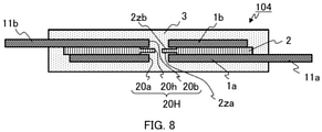
- Fig.8 is a sectional view showing a configuration of a bus bar module 104 according to Embodiment 4.
- counterbore portions 2za, 2zb are respectively provided at both circumferential edge portions of the spacer 2 around the hole 20h that are located on a side nearer to the bus bar 1a and on a side nearer to the bus bar 1b, so as to overlap with respective circumferential edge portions of the bus bars 1a, 1b around the holes 20a, 20b.
- bus bar module 104 The other configuration and manufacturing method of the bus bar module 104 according to Embodiment 4 are the same as those of the bus bar module 101 of Embodiment 1. Thus, the same reference numerals are given to the equivalent parts, so that description thereof will be omitted.
- the length of each of non-adhered regions between the bus bars 1a, 1b and the spacer 2 along the parallel planar regions 11c, 11d is further decreased while keeping the areas of the parallel planar regions 11c, 11d large. This makes it possible to reduce the amount of warpage to thereby suppress the stress concentration, and thus to suppress occurrence of cracking to thereby achieve improvement in the insulation performance, more significantly.
- the counterbore portions 2za, 2zb are provided respectively at its both circumferential edge portions around the hole 20h that are located on a side nearer to the bus bar 1a and on a side nearer to the bus bar 1b, so as to overlap with the respective circumferential edge portions around the hole 20a and the hole 20b.
- the length of each of non-adhered regions between the bus bars and the spacer along the parallel planar regions is further decreased while keeping the areas of the parallel planar regions large. This makes it possible to reduce the amount of warpage to thereby suppress the stress concentration, and thus to suppress occurrence of cracking to thereby achieve improvement in the insulation performance, more significantly.
- counterbore portions 2za, 2zb are provided at both circumferential edge portions of the spacer 2 around the hole 20h; however, this is not limitative.
- counterbore portions 11za, 11zb may be provided at the respective circumferential edge portions of the bus bars 1a, 1b around the holes 20a, 20b, that are each located on a side nearer to the spacer 2, so as to overlap with the respective circumferential edge portions of the spacer 2 around the hole 20h.
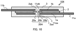
- the counterbore portions 2za, 11za and the counterbore portions 2zb, 11ab may be provided, respectively, at both of the respective mutually-corresponding circumferential edge portions of the spacer 2 around the hole 20h and the bus bars 1a, 1b around the holes 20a, 20b. Even in these cases, it is possible to achieve an effect that is similar to the effect according to Embodiment 4.
- Embodiment 2 a case has been described where the protrusion portions 2a, 2b are provided at the circumferential edge portions of the spacer 2 around the hole 20h; whereas in Embodiment 5, a case will be described where a protrusion portion is further provided at an outer peripheral portion of the spacer.
- Fig.11 is a sectional view showing a configuration of a bus bar module 105 according to Embodiment 5.
- the protrusion portions 2a, 2b are provided respectively at both circumferential edge portions of the spacer 2 that are located on a side nearer to the bus bar 1a and on a side nearer to the bus bar 1b; but also that a protrusion portion 2c as a third protrusion portion and a protrusion portion 2d as a fourth protrusion portion are provided respectively at outer peripheral portions of the spacer 2 so as to cover an end portion 11e of the bus bar 1a with respect to the parallel planar region 11c and an end portion 11f of the bus bar 1b with respect to the parallel planar region 11d.
- bus bar module 105 The other configuration and manufacturing method of the bus bar module 105 according to Embodiment 5 are the same as those of the bus bar module 102 of Embodiment 2. Thus, the same reference numerals are given to the equivalent parts, so that description thereof will be omitted.
- the protrusion portion 2c that covers the end portion 11e of the bus bar 1a with respect to the parallel planar region 11c, and the protrusion portion 2d that covers the end portion 11f of the bus bar 1b with respect to the parallel planar region 11d are provided at the outer peripheral portions of the spacer 2.
- the protrusion portions have vertically symmetrical shapes and dimensions, it is possible to suppress unbalance leading to warpage from occurring. This is effective in making it possible to further mitigate the stress concentration.
- each of the through-holes 20H, 21H, 22H, 23H and 24H in the figures has a circular shape; however, this is not limitative. It may have an elliptical shape or any given shape. Further, the description has been made assuming that the number of the bus bars 1a, 2b is two; however, three or more multiple bus bars may instead be provided.
- the spacer 2 is placed so as to entirely cover the parallel planar regions 11c, 11d; however, the parallel planar regions may be partly uncovered by the spacer 2 to the extent that the insulation is not affected.
- the bus bars 1a, 1b and the spacer 2, other than the terminal portions 11a, 11b of the bus bars 1a, 1b, are entirely covered with the resin mold 3 made of an insulating material; however, they may be partly exposed from the resin mold 3 to the extent that the insulation is not affected.
- 1a, 1b bus bar
Landscapes
- Engineering & Computer Science (AREA)
- Power Engineering (AREA)
- Inverter Devices (AREA)
- Structures Or Materials For Encapsulating Or Coating Semiconductor Devices Or Solid State Devices (AREA)
- Power Conversion In General (AREA)
Abstract
Description
- The present application relates to a bus bar module.
- In hybrid vehicles and electric vehicles, power conversion devices are employed which perform power conversion using semiconductor modules. As such a power conversion device, in Patent Document 1, an example is disclosed which is provided with multiple semiconductor modules for converting power and a bus bar module that is electrically connected to the power terminals of the respective semiconductor modules. The bus bar module has multiple bus bars each made of a conductor. The multiple bus bars are electrically connected, at their respective one end portions, to the power terminals of the respective semiconductor modules. Further, the other end portions of the bus bars are electrically connected to the respective phase terminals of a motor. The bus bars are each formed into a rectangular and flat-shaped cross section, and form parallel plates.
- Here, in the semiconductor module, a semiconductor switching element is incorporated, which serves as a power switch for turning ON/OFF a high voltage and a large amount of current. The potential at each of the bus bars is the same as the potential at the output terminal of each of the semiconductor modules, so that a potential difference corresponding to an AC or DC high voltage may be generated between the respective bus bars. Thus, it is necessary to ensure insulation between the bus bars.
- In this regard, in Patent Document 1, a structure is disclosed in which the multiple bus bars are encapsulated with an encapsulation resin having an insulation property, so that they are formed into a bus bar module. The power conversion device for in-vehicle use is required to be made compact since its mountable region inside the vehicle is restricted. Accordingly, it is also necessary to ensure insulation against its surrounding components other than bus bar, such as a control board, a capacitor, a cooler, etc. Thus, it is effective to encapsulate the multiple bus bars entirely with the insulating encapsulation resin. To achieve insulating resin-encapsulation, insert molding using the insulating resin may be employed. The insert molding is advantageous in productivity.
- Meanwhile, according to the insert molding, there is a problem that, because the encapsulation is achieved by injecting the insulating resin with a high pressure into a mold in which the multiple bus bars are installed, the bus bar may be deformed due to the pressure for injection, to cause a distance between bus bars to become shorter, resulting in deterioration in insulation performance. To deal with such a problem, in
Patent Document 2, a technique is disclosed in which an insulating plate is sandwiched as a spacer between respective bus bars to thereby ensure insulation between the bus bars. - With respect to a power conversion device configured with a semiconductor module and multiple bus bars, when a high-speed switching element, for example, an IGBT (Insulated Gate Bipolar Transistor), a MOSFET (metal-oxide-semiconductor field-effect transistor) or the like is used as a semiconductor element incorporated in the semiconductor module, it is required to reduce interconnection inductance as much as possible to thereby reduce the change rate of a current flowing through the semiconductor switching element.
- In order to reduce the interconnection inductance of the bus bars, similarly to the bus bar interconnection shown in
Patent Document 2, it is effective to form the multiple bus bars into parallel plates. Furthermore, it is effective to decrease the distance between bus bars and to increase the area of each parallel planar shape. In the parallel planar region, the interconnection inductance becomes smaller as the mutual inductance between the opposing bus bars becomes smaller. Further, when the distance between the bus bars is decreased, the mutual inductance becomes much smaller. -
- Patent Document 1:
Japanese Patent Application Laid-open No.2016-12965 Fig.1 ) - Patent Document 2:
Japanese Patent Application Laid-open No.2012-105382 Fig.1 ) - According to the bus-bar interconnection shown in
Patent Document 2, in order to ensure insulation between the bus bars, the insulating spacers sandwiched between bus bars is located so as to entirely cover the parallel planar regions, and the bus bars and the spacers, other than the terminal portions of the bus bars, are entirely covered with the encapsulation resin made of an insulating material; however, although the bus bar and the spacer are in contact with each other, they are not adhered to each other. Accordingly, the contact faces of the bus bar and the spacer are not adhered to each other, while they are both adhered to the encapsulation resin because of being entirely encapsulated with the resin through insert molding or the like. Since a difference in thermal expansion coefficient between the bus bar and the spacer is large, when the conventional bus bar module is exposed in high and low temperature environments, in the bus bar not joined to the spacer, warpage may occur due to a thermal strain difference between them caused by the temperature change. Further, the more the difference in thermal expansion coefficient is, the larger the amount of warpage becomes. In particular, when the area of the parallel planar region is large, the length of the non-adhered region becomes large, and the amount of warpage increases as the length of the non-adhered region becomes larger. Because of the warpage, a gap will be created along the non-adhered region, so that stress concentration may occur on an end portion of the non-adhered region. When the temperature change is repeated, cracking will occur firstly at the stress-concentrated portion of the bus bar. If the temperature change is further repeated, cracking will spread into the spacer. The spread of cracking causes a problem that the insulation property of the spacer is deteriorated, so that the insulation between the bus bars cannot be ensured. - This application discloses a technique for solving a problem as described above, and an object thereof is to suppress deterioration in the insulation property of the spacer by reducing stresses imposed thereon, to thereby provide a bus bar module which is highly reliable in insulation performance.
- A bus bar module disclosed in this application is characterized by comprising: a first bus bar having a first hole in a planar region thereof and made of an electrically conductive material; a second bus bar opposed to the first bus bar, having a second hole in a planar region thereof and at a position corresponding to the first hole, and made of an electrically conductive material; a spacer made of an insulating material, which is sandwiched between the first bus bar and the second bus bar, and in which a third hole is provided so as to overlap with the first hole and the second hole, and a resin mold covering the first bus bar, the second bus bar and the spacer; wherein a through-hole that is established by the first hole, the second hole and the third hole, is filled with a portion of the resin mold.
- According to this application, because of the provision of the resin mold formed of an encapsulation resin that fills the through-hole established by the holes of the respective bus bars and the hole of the spacer, stresses imposed on the spacer are reduced, so that it is possible to suppress deterioration in the insulation property, to thereby provide a bus bar module which is highly reliable in insulation performance.
-
-
Fig.1 is a set of plan views each showing a configuration of a bus bar module according to Embodiment 1. -
Fig.2 is sectional view showing a configuration of the bus bar module according to Embodiment 1. -
Fig.3 is a set of sectional views showing a manufacturing method of the bus bar module according to Embodiment1. -
Fig.4 is a sectional view showing a configuration of a bus bar module according toEmbodiment 2. -
Fig.5 is a sectional view showing a configuration of another bus bar module according toEmbodiment 2. -
Fig.6 is a set of plan views each showing a configuration of a bus bar module according toEmbodiment 3. -
Fig.7 is a sectional view showing a configuration of the bus bar module according toEmbodiment 3. -
Fig.8 is a sectional view showing a configuration of a bus bar module according to Embodiment 4. -
Fig.9 is a sectional view showing a configuration of another bus bar module according to Embodiment 4. -
Fig.10 is a sectional view showing a configuration of another bus bar module according to Embodiment 4. -
Fig.11 is a sectional view showing a configuration of a bus bar module according to Embodiment 5. -
Fig.1 is a set of plan views each showing a configuration of a bus bar module according to Embodiment 1, in whichFig.1 (a) shows the view after resin-encapsulation andFig.1(b) shows the view before resin-encapsulation.Fig.2 is a sectional view along arrow AA inFig.1(a) . As shown inFig.1(a), Fig.1(b) andFig.2 , abus bar module 101 is configured mainly with: abus bar 1a as a first bus bar and abus bar 1b as a second bus bar, which are opposed to each other and each made of an electrically conductive material; aspacer 2 which is sandwiched between thebus bars resin mold 3 formed of an encapsulation resin made of an insulating material that entirely covers thebus bars spacer 2, other thanterminal portions bus bars - The
bus bars bus bar 1a and thebus bar 1b, thespacer 2 is sandwiched therebetween so as to entirely cover their respective parallelplanar regions bus bars planar regions hole 20a as a first hole and ahole 20b as a second hole, that are mutually corresponding holes, are created, respectively. As a material of each of thebus bars - In order to ensure insulation between the
bus bar 1a and thebus bar 1b, thespacer 2 is provided so as to entirely cover the parallelplanar regions bus bar 1a and thebus bar 1b. In thespacer 2, at its central portion, ahole 20h as a third hole is created so as to overlap with theholes planar regions bus bars spacer 2, PPS (Poly Phenylene Sulfide) is used from the viewpoints of structural strength, thermal tolerance, insulation property and productivity. In the case of thespacer 2 made of PPS, it is favorable if its thickness is not less than 1 mm, from the viewpoints of structural strength and insulation property. Furthermore, in order to decrease the mutual inductance betweenbus bar 1a and thebus bar 1b, it is appropriate if the thickness of thespacer 2 is not more than 1.5 mm. Note that, other than PPS, an insulating resin such as PBT (Poly Butylene Terephthalate) or the like, may be used. Further, a thermally-conductive insulating sheet having a high thermal conductivity may instead be used. - The
resin mold 3 is formed in such a manner that thebus bar 1a and thebus bar 1b with thespacer 2 sandwiched therebetween, other than theterminal portions hole 20H established by theholes respective bus bars hole 20h of thespacer 2 is filled also with that resin. With respect to the power converter for in-vehicle use, PPS is used for theresin mold 3 from the viewpoints of structural strength, thermal tolerance, insulation property and productivity. Note that, other than PPS, an insulating resin used for insert molding, such as PBT or the like, may be used. - A feature of this application resides in that the through-
hole 20H established by theholes bus bars hole 20h of thespacer 2 is filled with a portion of theresin mold 3, to thereby adhere each of thebus bar 1a, thebus bar 1b and thespacer 2 to theresin mold 3 even in the through-hole 20H. - Accordingly, the length of each of non-adhered regions between the
bus bars spacer 2 along the parallelplanar regions planar regions - It is noted that, in Embodiment 1, the through-
hole 20H is positioned in the central portions of the parallelplanar regions planar regions bus bars - Next, a manufacturing method of the
bus bar module 101 according to Embodiment 1 to be provided as a power semiconductor device, will be described based onFig.3. Fig.3 is a set of sectional views showing a manufacturing method of thebus bar module 101 according to Embodiment 1. - First, as shown in
Fig.3(a) , thespacer 2 is placed on thebus bar 1a. At this time, the positions of thebus bar 1a and thespacer 2 are determined so that the respective central axes of thehole 20a of thebus bar 1a and thehole 20h of thespacer 2 coincide with each other. - Subsequently, as shown in
Fig.3(b) , thebus bar 1b is placed on thespacer 2. At this time, the positions of thebus bar 1b and thespacer 2 are determined so that the respective central axes of thehole 20b of thebus bar 1b and thehole 20h of thespacer 2 coincide with each other. As a result, the through-hole 20H is established. - Then, as shown in
Fig.3(c) , insert molding is carried out by inserting thebus bars spacer 2 sandwiched therebetween, into an unshown mold, and filling a region around thebus bars encapsulation resin 30. At this time, theencapsulation resin 30 is also filled in the through-hole 20H established by theholes bus bars hole 20h of thespacer 2. - Lastly, as shown in
Fig.3(d) , the thus-filledencapsulation resin 30 is cured by heating, so that theresin mold 3 is formed which covers thebus bars spacer 2 sandwiched therebetween and a portion of which fills up the through-hole 20H, to thereby provide thebus bar module 101. - In the thus-manufactured
bus bar module 101, although thespacer 2 is in contact with each of thebus bars resin mold 3 is adhered to each of thebus bar 1a, thebus bar 1b and thespacer 2. This is because thebus bar 1a, thebus bar 1b and thespacer 2 is insert-molded in theresin mold 3. - According to the
bus bar module 101 of this application, thebus bars spacer 2 sandwiched therebetween are covered with theencapsulation resin 30 and the through-hole 20H established by theholes bus bars hole 20h of thespacer 2 is filled with theencapsulation resin 30, and then theresin mold 3 is formed by heat-curing, so that each of thebus bar 1a, thebus bar 1b and thespacer 2 is adhered to theresin mold 3 even in the through-hole 20H. Accordingly, the length of each of non-adhered regions between thebus bars spacer 2 along the parallelplanar regions planar regions - As described above, the
bus bar module 101 according to Embodiment 1 comprises: thebus bar 1a having thehole 20a in the parallelplanar region 11c and made of an electrically conductive material; thebus bar 1b opposed to thebus bar 1a, having thehole 20b in the parallelplanar region 11d and at a position corresponding to thehole 20a, and made of an electrically conductive material; thespacer 2 made of an insulating material, which is sandwiched between thebus bar 1a and thebus bar 1b, and in which thehole 20h is provided so as to overlap with thehole 20a and thehole 20b; and theresin mold 3 covering thebus bars spacer 2; wherein the through-hole 20H that is established by thehole 20a, thehole 20b and thehole 20h, is filled with a portion of theresin mold 3. Accordingly, the length of each of non-adhered regions between the bus bars and the spacer along the respective parallel planar regions is decreased while keeping the areas of the parallel planar regions large. This makes it possible to reduce the amount of warpage to thereby suppress the stress concentration, and thus to suppress occurrence of cracking to thereby achieve improvement in the insulation performance. - Further, because the fixed position is established, there is also provided an effect that the quake resistance is improved. Furthermore, when the thickness of the
bus bar 1a and the thickness of thebus bar 1b are equal to each other, and the thickness of a portion of theresin mold 3 located on thebus bar 1a and the thickness of a portion of theresin mold 3 located on thebus bar 1b are equal to each other, it is possible to suppress unbalance leading to warpage from occurring in the vertical direction. This is effective in making it possible to further mitigate stress concentration on the spacer. - In Embodiment 1, a case has been described where the positions of the
bus bars spacer 2 are determined so that the central axes of thehole 20a, thehole 20b and thehole 20h coincide with each other, whereas inEmbodiment 2, a case will be described where a protrusion portion is provided at a circumferential edge portion of the spacer around the hole thereof. -
Fig.4 is a sectional view showing a configuration of a bus bar module according toEmbodiment 2. As shown inFig.4 , in abus bar module 102, at a circumferential edge portion of thespacer 2 around ahole 21h being located on a side nearer to thebus bar 1b, aprotrusion portion 2b as a first protrusion portion is provided so as to cover the inner wall of ahole 21b of thebus bar 1b. - In a manufacturing method of the
bus bar module 102, theprotrusion portion 2b of thespacer 2 is formed to be insertable into thehole 21b of thebus bar 1b, so that, at the time of placing thebus bar 1b on thespacer 2, their positions can easily be determined merely by insertion of theprotrusion portion 2b into thehole 20b, without depending on a placing operation to be performed so that the central axes of thehole 20b and thehole 21h coincide with each other. - The other configuration and manufacturing method of the
bus bar module 102 according toEmbodiment 2 are the same as those of thebus bar module 101 of Embodiment 1. Thus, the same reference numerals are given to the equivalent parts, so that description thereof will be omitted. - As described above, according to the
bus bar module 102 ofEmbodiment 2, in thespacer 2, theprotrusion portion 2b is provided at its circumferential edge portion around thehole 21h being located on a side nearer to thebus bar 1b, so as to cover thehole 21b. Thus, in the manufacturing method of the bus bar module, the positions can easily be determined merely by insertion of the protrusion portion into the hole of the bus bar, without depending on a placing operation to be performed so that the central axes of the hole of the bus bar and the hole of the spacer coincide with each other. - It is noted that, in
Embodiment 2, theprotrusion portion 2b is provided at the circumferential edge portion of thespacer 2 around thehole 21h being located on a side nearer to thebus bar 1b; however, this is not limitative. Aprotrusion portion 2a as a second protrusion portion may be provided at a circumferential edge portion of thespacer 2 around thehole 21h being located on a side nearer to thebus bar 1a, so as to cover thehole 21a, and as shown inFig.5 , theprotrusion portions spacer 2 around thehole 22h that are located on a side nearer to thebus bar 1a and on a side nearer to thebus bar 1b, so as to cover theholes Embodiment 2. - Further, when the
protrusion portions spacer 2 around thehole 21h that are located on a side nearer to thebus bar 1a and on a side nearer to thebus bar 1b, it is possible to get a large insulation creepage distance between the bus bars, even if the filling efficiency of theencapsulation resin 30 is insufficient in the through-hole. This is effective in making it possible to keep the bus bar module excellent in insulation performance. Furthermore, when theprotrusion portions bus bar 1a-side and on the bus bar lb-side, have vertically symmetrical shapes and dimensions, it is possible to suppress unbalance leading to warpage from occurring. This is effective in making it possible to further mitigate the stress concentration. - In Embodiment 1, a case has been described where the through-hole H filled with a portion of the
resin mold 3 is provided at one location in thebus bar module 101, whereas inEmbodiment 3, a case will be described where the through-hole filled with a portion of the resin mold is provided at each of multiple locations therein. -
Fig.6 is a set of plan views each showing a configuration of a bus bar module according toEmbodiment 3, in whichFig.6(a) shows the view after resin-encapsulation andFig.6(b) shows the view before resin-encapsulation.Fig.7 is a sectional view along arrow BB inFig.6(a) . As shown inFig.6(a), Fig.6(b) andFig.7 , abus bar module 103 has a through-hole 23H (ahole 23a, ahole 23h and ahole 23b) and a through-hole 24H (ahole 24a, ahole 24h and ahole 24b) at two locations corresponding to respective central portions in the bisected regions of the parallelplanar regions bus bars - In a manufacturing method of the
bus bar module 103, at the time of placing thespacer 2 on thebus bar 1a and placing thebus bar 1b on thespacer 2, their positions are determined so that the through-hole 23H and the through-hole 24H are established at the two locations, and then the through-hole 23H and the through-hole 24H are both filled with theencapsulation resin 30. - The other configuration and manufacturing method of the
bus bar module 103 according toEmbodiment 3 are the same as those of thebus bar module 101 of Embodiment 1. Thus, the same reference numerals are given to the equivalent parts, so that description thereof will be omitted. - Accordingly, the number of the fixed positions increases, so that the length of each of non-adhered regions between the
bus bars spacer 2 along the parallelplanar regions planar regions - It is noted that, in
Embodiment 3, the number of the through-holes holes planar regions planar regions bus bars - As described above, the
bus bar module 103 according toEmbodiment 3 is provided with the multiple through-holes - In Embodiment 1, a case has been described where the
hole 20a, thehole 20b and thehole 20h of thebus bars spacer 2, are mutually overlapped, without modification, to thereby establish the through-hole 20H, whereas in Embodiment 4, a case will be described where a counterbore portion is provided at a circumferential edge portion around the hole. -
Fig.8 is a sectional view showing a configuration of abus bar module 104 according to Embodiment 4. As shown inFig.8 , in thebus bar module 104, counterbore portions 2za, 2zb are respectively provided at both circumferential edge portions of thespacer 2 around thehole 20h that are located on a side nearer to thebus bar 1a and on a side nearer to thebus bar 1b, so as to overlap with respective circumferential edge portions of thebus bars holes - The other configuration and manufacturing method of the
bus bar module 104 according to Embodiment 4 are the same as those of thebus bar module 101 of Embodiment 1. Thus, the same reference numerals are given to the equivalent parts, so that description thereof will be omitted. - Accordingly, the length of each of non-adhered regions between the
bus bars spacer 2 along the parallelplanar regions planar regions - As described above, according to the
bus bar module 104 of Embodiment 4, in thespacer 2, the counterbore portions 2za, 2zb are provided respectively at its both circumferential edge portions around thehole 20h that are located on a side nearer to thebus bar 1a and on a side nearer to thebus bar 1b, so as to overlap with the respective circumferential edge portions around thehole 20a and thehole 20b. Thus, the length of each of non-adhered regions between the bus bars and the spacer along the parallel planar regions is further decreased while keeping the areas of the parallel planar regions large. This makes it possible to reduce the amount of warpage to thereby suppress the stress concentration, and thus to suppress occurrence of cracking to thereby achieve improvement in the insulation performance, more significantly. - It is noted that, in Embodiment 4, the counterbore portions 2za, 2zb are provided at both circumferential edge portions of the
spacer 2 around thehole 20h; however, this is not limitative. As shown inFig.9 , counterbore portions 11za, 11zb may be provided at the respective circumferential edge portions of thebus bars holes spacer 2, so as to overlap with the respective circumferential edge portions of thespacer 2 around thehole 20h. Further, as shown inFig.10 , the counterbore portions 2za, 11za and the counterbore portions 2zb, 11ab may be provided, respectively, at both of the respective mutually-corresponding circumferential edge portions of thespacer 2 around thehole 20h and thebus bars holes - In
Embodiment 2, a case has been described where theprotrusion portions spacer 2 around thehole 20h; whereas in Embodiment 5, a case will be described where a protrusion portion is further provided at an outer peripheral portion of the spacer. -
Fig.11 is a sectional view showing a configuration of abus bar module 105 according to Embodiment 5. As shown inFig.11 , in thebus bar module 105, not only that theprotrusion portions spacer 2 that are located on a side nearer to thebus bar 1a and on a side nearer to thebus bar 1b; but also that aprotrusion portion 2c as a third protrusion portion and aprotrusion portion 2d as a fourth protrusion portion are provided respectively at outer peripheral portions of thespacer 2 so as to cover anend portion 11e of thebus bar 1a with respect to the parallelplanar region 11c and anend portion 11f of thebus bar 1b with respect to the parallelplanar region 11d. - The other configuration and manufacturing method of the
bus bar module 105 according to Embodiment 5 are the same as those of thebus bar module 102 ofEmbodiment 2. Thus, the same reference numerals are given to the equivalent parts, so that description thereof will be omitted. - Accordingly, it is possible to get a large insulation creepage distance between the bus bars, even if the filling efficiency of the
encapsulation resin 30 is insufficient around the outer peripheral portion. This is effective in making it possible to keep the bus bar module excellent in insulation performance. Moreover, when theprotrusion portions bus bar 1a-side and on thebus bar 1b-side, have vertically symmetrical shapes and dimensions, it is possible to suppress unbalance leading to warpage from occurring. This is effective in making it possible to further mitigate the stress concentration. - As described above, according to the
bus bar module 105 of Embodiment 5, in thespacer 2, theprotrusion portion 2c that covers theend portion 11e of thebus bar 1a with respect to the parallelplanar region 11c, and theprotrusion portion 2d that covers theend portion 11f of thebus bar 1b with respect to the parallelplanar region 11d, are provided at the outer peripheral portions of thespacer 2. Thus, it is possible to get a large insulation creepage distance between the bus bars, even if the filling efficiency of the encapsulation resin is insufficient around the outer peripheral portion. This is effective in making it possible to keep the bus bar module excellent in insulation performance. Furthermore, when these protrusion portions have vertically symmetrical shapes and dimensions, it is possible to suppress unbalance leading to warpage from occurring. This is effective in making it possible to further mitigate the stress concentration. - It is noted that, in the foregoing Embodiments, each of the through-
holes bus bars - Further, it has been assumed that, in order to ensure insulation between bus bars, the
spacer 2 is placed so as to entirely cover the parallelplanar regions spacer 2 to the extent that the insulation is not affected. Furthermore, it has been assumed that thebus bars spacer 2, other than theterminal portions bus bars resin mold 3 made of an insulating material; however, they may be partly exposed from theresin mold 3 to the extent that the insulation is not affected. - In this application, a variety of exemplary embodiments and examples are described; however, every characteristic, configuration or function that is described in one or more embodiments, is not limited to being applied to a specific embodiment, and may be applied singularly or in any of various combinations thereof to another embodiment. Accordingly, an infinite number of modified examples that are not exemplified here are supposed within the technical scope disclosed in the present description. For example, such cases shall be included where at least one configuration element is modified; where at least one configuration element is added or omitted; and furthermore, where at least one configuration element is extracted and combined with a configuration element of another embodiment.
- 1a, 1b: bus bar, 2: spacer, 2a, 2b, 2c, 2d: protrusion portion, 2za, 2zb, 11za, 11zb: counterbore portion, 3: resin mold, 11c, 11d: parallel planar region, 20a, 20b, 20h, 21a, 21b, 21h, 22a, 22b, 22h, 23a, 23b, 23h, 24a, 24b, 24h: hole, 20H, 21H, 22H, 23H, 24H: through-hole, 101, 102, 103, 104, 105: bus bar module.
Claims (12)
- A bus bar module, comprising:a first bus bar having a first hole in a planar region thereof and made of an electrically conductive material;a second bus bar opposed to the first bus bar, having a second hole in a planar region thereof and at a position corresponding to the first hole, and made of an electrically conductive material;a spacer made of an insulating material, which is sandwiched between the first bus bar and the second bus bar, and in which a third hole is provided so as to overlap with the first hole and the second hole, anda resin mold covering the first bus bar, the second bus bar and the spacer;wherein a through-hole that is established by the first hole, the second hole and the third hole, is filled with a portion of the resin mold.
- The bus bar module according to Claim 1, wherein the spacer is provided with a first protrusion portion at its circumferential edge portion around the third hole being located on a side nearer to the first bus bar, said first protrusion portion covering an inner wall of the first hole.
- The bus bar module according to Claim 1, wherein the spacer is provided with a second protrusion portion at its circumferential edge portion around the third hole being located on a side nearer to the second bus bar, said second protrusion portion covering an inner wall of the second hole.
- The bus bar module according to Claim 2, wherein the spacer is provided with a second protrusion portion at its circumferential edge portion around the third hole being located on a side nearer to the second bus bar, said second protrusion portion covering an inner wall of the second hole.
- The bus bar module according to Claim 4, wherein the first protrusion portion and the second protrusion portion of the spacer are plane symmetrical with respect to a plane passing a thickness-direction center of the spacer.
- The bus bar module according to Claim 4 or Claim 5, wherein the spacer is provided with, at its outer peripheral portions, a third protrusion portion that covers an end portion of the first bus bar with respect to the planar region thereof and a fourth protrusion portion that covers an end portion of the second bus bar with respect to the planar region thereof.
- The bus bar module according to Claim 1, wherein the spacer is provided with counterbore portions at its both circumferential edge portions around the third hole that are located on a side nearer to the first bus bar and on a side nearer to the second bus bar, respectively, said counterbore portions being provided so as to overlap with circumferential edge portions of the bus bars around the first hole and the second hole.
- The bus bar module according to Claim 1 or Claim 7, wherein the first bus bar and the second bus bar are provided with their respective counterbore portions at their circumferential edge portions around the first hole and the second hole each being located on a side nearer to the spacer, said counterbore portions being provided so as to overlap with circumferential edge portions of the spacer on its both sides nearer to the respective bus bars.
- The bus bar module according to any one of Claim 1 through Claim 8, wherein multiple through-holes each being said through-hole are provided.
- The bus bar module according to any one of Claim 1 through Claim 9, wherein a thickness of the first bus bar is equal to that of the second bus bar, and a thickness of a portion of the resin mold located on the first bus bar is equal to that of a portion of the resin mold located on the second bus bar.
- The bus bar module according to any one of Claim 1 through Claim 10, wherein the spacer is made of PPS or PBT.
- The bus bar module according to any one of Claim 1 through Claim 11, wherein the spacer has a thickness that is not less than 1 mm and not more than 1.5 mm.
Applications Claiming Priority (2)
| Application Number | Priority Date | Filing Date | Title |
|---|---|---|---|
| JP2019080717A JP6682027B1 (en) | 2019-04-22 | 2019-04-22 | Busbar module |
| PCT/JP2019/036065 WO2020217565A1 (en) | 2019-04-22 | 2019-09-13 | Bus bar module |
Publications (2)
| Publication Number | Publication Date |
|---|---|
| EP3961885A1 true EP3961885A1 (en) | 2022-03-02 |
| EP3961885A4 EP3961885A4 (en) | 2022-06-01 |
Family
ID=70166326
Family Applications (1)
| Application Number | Title | Priority Date | Filing Date |
|---|---|---|---|
| EP19926427.6A Withdrawn EP3961885A4 (en) | 2019-04-22 | 2019-09-13 | BUSBAR MODULE |
Country Status (5)
| Country | Link |
|---|---|
| US (1) | US12015337B2 (en) |
| EP (1) | EP3961885A4 (en) |
| JP (1) | JP6682027B1 (en) |
| CN (1) | CN113748591B (en) |
| WO (1) | WO2020217565A1 (en) |
Families Citing this family (5)
| Publication number | Priority date | Publication date | Assignee | Title |
|---|---|---|---|---|
| JP7380428B2 (en) * | 2020-05-29 | 2023-11-15 | 日産自動車株式会社 | power converter |
| JP6999749B2 (en) * | 2020-06-16 | 2022-02-04 | 三菱電機株式会社 | Electrical equipment wiring parts |
| DE102021210938A1 (en) * | 2021-09-30 | 2023-03-30 | Zf Friedrichshafen Ag | Inverter with optimized electromagnetic behavior |
| JP2023158944A (en) * | 2022-04-19 | 2023-10-31 | 三井化学株式会社 | Busbar laminate and method for manufacturing busbar laminate |
| DE102022207767B3 (en) * | 2022-07-28 | 2023-10-05 | Magna powertrain gmbh & co kg | Power module and method for producing the power module |
Family Cites Families (20)
| Publication number | Priority date | Publication date | Assignee | Title |
|---|---|---|---|---|
| US3104276A (en) * | 1959-06-02 | 1963-09-17 | Ite Circuit Breaker Ltd | Through-bolt joint for bus duct |
| JPS56110584U (en) * | 1980-01-28 | 1981-08-26 | ||
| JPH09161890A (en) * | 1995-12-07 | 1997-06-20 | Asahi Electric Works Ltd | Electric connecting device having conductive connecting structure, and connecting surface polishing tool therefor |
| JP3809346B2 (en) * | 2001-06-15 | 2006-08-16 | トヨタ自動車株式会社 | Switching circuit |
| JP4419416B2 (en) * | 2003-03-31 | 2010-02-24 | パナソニック株式会社 | Metallized film capacitors |
| JP4776555B2 (en) * | 2007-01-23 | 2011-09-21 | 古河電気工業株式会社 | Metal core multilayer printed wiring board |
| JP4905254B2 (en) * | 2007-05-25 | 2012-03-28 | トヨタ自動車株式会社 | Manufacturing method of bus bar with integrated capacitor |
| JP4935883B2 (en) * | 2009-11-27 | 2012-05-23 | 株式会社デンソー | Bus bar assembly |
| JP5212351B2 (en) * | 2009-12-22 | 2013-06-19 | トヨタ自動車株式会社 | Bus bar structure and manufacturing method thereof |
| JP5549491B2 (en) * | 2010-09-06 | 2014-07-16 | 日立金属株式会社 | Busbar module manufacturing method and busbar module |
| JP2012105382A (en) | 2010-11-08 | 2012-05-31 | Hitachi Ltd | Semiconductor device |
| JP6038695B2 (en) * | 2013-03-15 | 2016-12-07 | シャープ株式会社 | Structure and manufacturing method thereof |
| JP6064805B2 (en) * | 2013-06-19 | 2017-01-25 | 富士電機株式会社 | Insulated bus bar and manufacturing method thereof |
| JP2016012965A (en) | 2014-06-27 | 2016-01-21 | 株式会社デンソー | Power conversion apparatus |
| CN108352252B (en) * | 2015-11-10 | 2020-03-24 | 松下知识产权经营株式会社 | Film capacitors |
| JP6443688B2 (en) * | 2015-12-16 | 2018-12-26 | 株式会社オートネットワーク技術研究所 | Circuit structure and electrical junction box |
| RU2726169C1 (en) | 2016-12-19 | 2020-07-09 | Абб Швайц Аг | Multi-phase power supply bus for electric power transmission, method of manufacturing thereof and switching cabinet, including such power supply bus |
| EP3337304B1 (en) | 2016-12-19 | 2020-02-05 | ABB Schweiz AG | Multi-phase busbur for conductiong electric energy and method of manufacturing the same |
| CN106971992B (en) * | 2017-05-09 | 2019-04-05 | 中车株洲电力机车研究所有限公司 | A half-bridge power semiconductor module |
| CN107769133A (en) * | 2017-10-25 | 2018-03-06 | 镇江市益宝电气科技有限公司 | A kind of high-performance bus frame and its moulding process |
-
2019
- 2019-04-22 JP JP2019080717A patent/JP6682027B1/en active Active
- 2019-09-13 WO PCT/JP2019/036065 patent/WO2020217565A1/en not_active Ceased
- 2019-09-13 CN CN201980095441.5A patent/CN113748591B/en active Active
- 2019-09-13 EP EP19926427.6A patent/EP3961885A4/en not_active Withdrawn
- 2019-09-13 US US17/432,983 patent/US12015337B2/en active Active
Also Published As
| Publication number | Publication date |
|---|---|
| JP2020178504A (en) | 2020-10-29 |
| CN113748591A (en) | 2021-12-03 |
| US20220173583A1 (en) | 2022-06-02 |
| JP6682027B1 (en) | 2020-04-15 |
| WO2020217565A1 (en) | 2020-10-29 |
| US12015337B2 (en) | 2024-06-18 |
| EP3961885A4 (en) | 2022-06-01 |
| CN113748591B (en) | 2024-07-30 |
Similar Documents
| Publication | Publication Date | Title |
|---|---|---|
| US12015337B2 (en) | Bus bar module | |
| JP7457812B2 (en) | Semiconductor Module | |
| EP3726672B1 (en) | Busbar connection apparatus | |
| US20210391236A1 (en) | Semiconductor module, power conversion device, and manufacturing method of semiconductor module | |
| DE102015224422A1 (en) | Electronic circuit unit | |
| US11495527B2 (en) | Semiconductor module | |
| CN104854671A (en) | Case-mold-type capacitor and method for producing same | |
| US20190273040A1 (en) | Manufacturing of a power semiconductor module | |
| US20140242838A1 (en) | Terminal block and electronic device comprising same | |
| CN101946362A (en) | Battery module comprising an integrated electrical component | |
| US20250226759A1 (en) | Power electronics system | |
| US11056415B2 (en) | Semiconductor device | |
| CN218784016U (en) | Electrical assembly and voltage converter | |
| JP7543911B2 (en) | Power storage device | |
| JP2011035277A (en) | Bus bar assembly and method of manufacturing the same | |
| WO2021015050A1 (en) | Electric circuit device | |
| CN113808782B (en) | Electrical equipment wiring member | |
| JP2024056186A (en) | Capacitor | |
| US20230128774A1 (en) | Power module with overmoulding, devices comprising such a power module and method for manufacturing a power module with overmoulding | |
| CN111684587B (en) | Semiconductor device with a semiconductor device having a plurality of semiconductor chips | |
| US20230307332A1 (en) | Power Semiconductor Module and Method for Producing a Power Semiconductor Module | |
| US20260060136A1 (en) | Power Electronics Device and Plug Connector Assembly Having an Electrically Insulative Compressible Body | |
| CN111033723B (en) | power semiconductor module | |
| US12444933B2 (en) | Surge suppression device | |
| CN221668830U (en) | Integrated busbar terminal and IGBT side frame |
Legal Events
| Date | Code | Title | Description |
|---|---|---|---|
| STAA | Information on the status of an ep patent application or granted ep patent |
Free format text: STATUS: THE INTERNATIONAL PUBLICATION HAS BEEN MADE |
|
| PUAI | Public reference made under article 153(3) epc to a published international application that has entered the european phase |
Free format text: ORIGINAL CODE: 0009012 |
|
| STAA | Information on the status of an ep patent application or granted ep patent |
Free format text: STATUS: REQUEST FOR EXAMINATION WAS MADE |
|
| 17P | Request for examination filed |
Effective date: 20210916 |
|
| AK | Designated contracting states |
Kind code of ref document: A1 Designated state(s): AL AT BE BG CH CY CZ DE DK EE ES FI FR GB GR HR HU IE IS IT LI LT LU LV MC MK MT NL NO PL PT RO RS SE SI SK SM TR |
|
| REG | Reference to a national code |
Ref country code: DE Ref legal event code: R079 Free format text: PREVIOUS MAIN CLASS: H02M0001000000 Ipc: H02M0003000000 |
|
| A4 | Supplementary search report drawn up and despatched |
Effective date: 20220503 |
|
| RIC1 | Information provided on ipc code assigned before grant |
Ipc: H02G 5/00 20060101ALI20220426BHEP Ipc: H02M 1/00 20060101ALI20220426BHEP Ipc: H02M 7/00 20060101ALI20220426BHEP Ipc: H02M 3/00 20060101AFI20220426BHEP |
|
| DAV | Request for validation of the european patent (deleted) | ||
| DAX | Request for extension of the european patent (deleted) | ||
| STAA | Information on the status of an ep patent application or granted ep patent |
Free format text: STATUS: EXAMINATION IS IN PROGRESS |
|
| 17Q | First examination report despatched |
Effective date: 20230612 |
|
| REG | Reference to a national code |
Ref country code: DE Ref legal event code: R079 Free format text: PREVIOUS MAIN CLASS: H02M0003000000 Ipc: H02M0007000000 |
|
| RIC1 | Information provided on ipc code assigned before grant |
Ipc: H02G 5/00 20060101ALI20250120BHEP Ipc: H02M 7/00 20060101AFI20250120BHEP |
|
| GRAP | Despatch of communication of intention to grant a patent |
Free format text: ORIGINAL CODE: EPIDOSNIGR1 |
|
| STAA | Information on the status of an ep patent application or granted ep patent |
Free format text: STATUS: GRANT OF PATENT IS INTENDED |
|
| INTG | Intention to grant announced |
Effective date: 20250306 |
|
| STAA | Information on the status of an ep patent application or granted ep patent |
Free format text: STATUS: THE APPLICATION IS DEEMED TO BE WITHDRAWN |
|
| 18D | Application deemed to be withdrawn |
Effective date: 20250708 |