EP3961879A2 - Stator unit, motor-operated valve, and method for manufacturing stator unit - Google Patents
Stator unit, motor-operated valve, and method for manufacturing stator unit Download PDFInfo
- Publication number
- EP3961879A2 EP3961879A2 EP21192144.0A EP21192144A EP3961879A2 EP 3961879 A2 EP3961879 A2 EP 3961879A2 EP 21192144 A EP21192144 A EP 21192144A EP 3961879 A2 EP3961879 A2 EP 3961879A2
- Authority
- EP
- European Patent Office
- Prior art keywords
- stator
- circumferential surface
- cover
- wall portion
- jig
- Prior art date
- Legal status (The legal status is an assumption and is not a legal conclusion. Google has not performed a legal analysis and makes no representation as to the accuracy of the status listed.)
- Granted
Links
Images



Classifications
-
- H—ELECTRICITY
- H02—GENERATION; CONVERSION OR DISTRIBUTION OF ELECTRIC POWER
- H02K—DYNAMO-ELECTRIC MACHINES
- H02K1/00—Details of the magnetic circuit
- H02K1/06—Details of the magnetic circuit characterised by the shape, form or construction
- H02K1/12—Stationary parts of the magnetic circuit
- H02K1/14—Stator cores with salient poles
- H02K1/146—Stator cores with salient poles consisting of a generally annular yoke with salient poles
-
- H—ELECTRICITY
- H02—GENERATION; CONVERSION OR DISTRIBUTION OF ELECTRIC POWER
- H02K—DYNAMO-ELECTRIC MACHINES
- H02K5/00—Casings; Enclosures; Supports
- H02K5/04—Casings or enclosures characterised by the shape, form or construction thereof
- H02K5/12—Casings or enclosures characterised by the shape, form or construction thereof specially adapted for operating in liquid or gas
- H02K5/128—Casings or enclosures characterised by the shape, form or construction thereof specially adapted for operating in liquid or gas using air-gap sleeves or air-gap discs
-
- F—MECHANICAL ENGINEERING; LIGHTING; HEATING; WEAPONS; BLASTING
- F16—ENGINEERING ELEMENTS AND UNITS; GENERAL MEASURES FOR PRODUCING AND MAINTAINING EFFECTIVE FUNCTIONING OF MACHINES OR INSTALLATIONS; THERMAL INSULATION IN GENERAL
- F16K—VALVES; TAPS; COCKS; ACTUATING-FLOATS; DEVICES FOR VENTING OR AERATING
- F16K31/00—Actuating devices; Operating means; Releasing devices
- F16K31/02—Actuating devices; Operating means; Releasing devices electric; magnetic
- F16K31/04—Actuating devices; Operating means; Releasing devices electric; magnetic using a motor
-
- H—ELECTRICITY
- H02—GENERATION; CONVERSION OR DISTRIBUTION OF ELECTRIC POWER
- H02K—DYNAMO-ELECTRIC MACHINES
- H02K1/00—Details of the magnetic circuit
- H02K1/06—Details of the magnetic circuit characterised by the shape, form or construction
- H02K1/12—Stationary parts of the magnetic circuit
- H02K1/18—Means for mounting or fastening magnetic stationary parts on to, or to, the stator structures
-
- H—ELECTRICITY
- H02—GENERATION; CONVERSION OR DISTRIBUTION OF ELECTRIC POWER
- H02K—DYNAMO-ELECTRIC MACHINES
- H02K1/00—Details of the magnetic circuit
- H02K1/06—Details of the magnetic circuit characterised by the shape, form or construction
- H02K1/12—Stationary parts of the magnetic circuit
- H02K1/18—Means for mounting or fastening magnetic stationary parts on to, or to, the stator structures
- H02K1/185—Means for mounting or fastening magnetic stationary parts on to, or to, the stator structures to outer stators
-
- H—ELECTRICITY
- H02—GENERATION; CONVERSION OR DISTRIBUTION OF ELECTRIC POWER
- H02K—DYNAMO-ELECTRIC MACHINES
- H02K15/00—Processes or apparatus specially adapted for manufacturing, assembling, maintaining or repairing of dynamo-electric machines
- H02K15/02—Processes or apparatus specially adapted for manufacturing, assembling, maintaining or repairing of dynamo-electric machines of stator or rotor bodies
- H02K15/021—Magnetic cores
- H02K15/022—Magnetic cores with salient poles
-
- H—ELECTRICITY
- H02—GENERATION; CONVERSION OR DISTRIBUTION OF ELECTRIC POWER
- H02K—DYNAMO-ELECTRIC MACHINES
- H02K15/00—Processes or apparatus specially adapted for manufacturing, assembling, maintaining or repairing of dynamo-electric machines
- H02K15/12—Impregnating, moulding insulation, heating or drying of windings, stators, rotors or machines
-
- H—ELECTRICITY
- H02—GENERATION; CONVERSION OR DISTRIBUTION OF ELECTRIC POWER
- H02K—DYNAMO-ELECTRIC MACHINES
- H02K16/00—Machines with more than one rotor or stator
- H02K16/04—Machines with one rotor and two stators
-
- H—ELECTRICITY
- H02—GENERATION; CONVERSION OR DISTRIBUTION OF ELECTRIC POWER
- H02K—DYNAMO-ELECTRIC MACHINES
- H02K3/00—Details of windings
- H02K3/46—Fastening of windings on the stator or rotor structure
- H02K3/50—Fastening of winding heads, equalising connectors, or connections thereto
-
- H—ELECTRICITY
- H02—GENERATION; CONVERSION OR DISTRIBUTION OF ELECTRIC POWER
- H02K—DYNAMO-ELECTRIC MACHINES
- H02K3/00—Details of windings
- H02K3/46—Fastening of windings on the stator or rotor structure
- H02K3/52—Fastening salient pole windings or connections thereto
- H02K3/521—Fastening salient pole windings or connections thereto applicable to stators only
-
- H—ELECTRICITY
- H02—GENERATION; CONVERSION OR DISTRIBUTION OF ELECTRIC POWER
- H02K—DYNAMO-ELECTRIC MACHINES
- H02K5/00—Casings; Enclosures; Supports
- H02K5/04—Casings or enclosures characterised by the shape, form or construction thereof
- H02K5/08—Insulating casings
-
- H—ELECTRICITY
- H02—GENERATION; CONVERSION OR DISTRIBUTION OF ELECTRIC POWER
- H02K—DYNAMO-ELECTRIC MACHINES
- H02K5/00—Casings; Enclosures; Supports
- H02K5/24—Casings; Enclosures; Supports specially adapted for suppression or reduction of noise or vibrations
-
- H—ELECTRICITY
- H02—GENERATION; CONVERSION OR DISTRIBUTION OF ELECTRIC POWER
- H02K—DYNAMO-ELECTRIC MACHINES
- H02K1/00—Details of the magnetic circuit
- H02K1/06—Details of the magnetic circuit characterised by the shape, form or construction
- H02K1/12—Stationary parts of the magnetic circuit
- H02K1/14—Stator cores with salient poles
- H02K1/145—Stator cores with salient poles having an annular coil, e.g. of the claw-pole type
-
- H—ELECTRICITY
- H02—GENERATION; CONVERSION OR DISTRIBUTION OF ELECTRIC POWER
- H02K—DYNAMO-ELECTRIC MACHINES
- H02K15/00—Processes or apparatus specially adapted for manufacturing, assembling, maintaining or repairing of dynamo-electric machines
- H02K15/02—Processes or apparatus specially adapted for manufacturing, assembling, maintaining or repairing of dynamo-electric machines of stator or rotor bodies
- H02K15/028—Fastening stator or rotor bodies to casings, supports, shafts or hubs
-
- H—ELECTRICITY
- H02—GENERATION; CONVERSION OR DISTRIBUTION OF ELECTRIC POWER
- H02K—DYNAMO-ELECTRIC MACHINES
- H02K15/00—Processes or apparatus specially adapted for manufacturing, assembling, maintaining or repairing of dynamo-electric machines
- H02K15/14—Casings; Enclosures; Supports
-
- H—ELECTRICITY
- H02—GENERATION; CONVERSION OR DISTRIBUTION OF ELECTRIC POWER
- H02K—DYNAMO-ELECTRIC MACHINES
- H02K2213/00—Specific aspects, not otherwise provided for and not covered by codes H02K2201/00 - H02K2211/00
- H02K2213/03—Machines characterised by numerical values, ranges, mathematical expressions or similar information
-
- H—ELECTRICITY
- H02—GENERATION; CONVERSION OR DISTRIBUTION OF ELECTRIC POWER
- H02K—DYNAMO-ELECTRIC MACHINES
- H02K3/00—Details of windings
- H02K3/46—Fastening of windings on the stator or rotor structure
- H02K3/52—Fastening salient pole windings or connections thereto
- H02K3/521—Fastening salient pole windings or connections thereto applicable to stators only
- H02K3/525—Annular coils, e.g. for cores of the claw-pole type
Definitions
- the present invention relates to a stator unit for use in a motor-operated valve, to a motor-operated valve including a stator unit, and to a method for manufacturing a stator unit.
- stator units according to the related art are disclosed in Japanese Unexamined Patent Application Publication No. 2001-343085 (Patent Literature 1) and Japanese Unexamined Patent Application Publication No. 2006-20480 (Patent Literature 2).
- the stator unit (coil for a motor-operated valve) disclosed in Patent Literature 1 includes a cover and a stator.
- the cover is in the shape of a cap.
- the stator has a hollow cylindrical shape.
- the stator includes a metal component, a coil wire, and a mold made of rigid resin.
- the peripheral part of the body constituted of the metal component and the coil wire is covered with the mold.
- the stator is accommodated in the cover.
- the space between the cover and the stator is filled with filling resin that is flexible.
- the process for manufacturing such a stator unit may include the steps of: (1) forming a stator by insert molding; (2) placing the stator in a cover; (3) inserting a mandrel (jig) into a stator to position the cover and the stator; (4) clamping the mandrel and the cover; (5) pouring filling resin in liquid form into the cover with its lower end facing upward; and (6) removing the mandrel after the filling resin sets.
- the stator unit obtained by this process is in finished form.
- the stator unit (electromagnetic actuator) disclosed in Patent Literature 2 includes a cover and a stator. The space between the cover and the stator is filled with filling resin.
- the stator described in Patent Literature 2 is formed by insert molding in such a manner that a gap on an internal circumferential surface of a metal component is filled with rigid resin.
- the stator includes an annular rib.
- the rib fits into an annular groove in an upper-end wall portion of the cover. When filling resin in liquid form is poured into the cover, the rib in the groove keeps the filling resin from leaking into the stator.
- This structure eliminates the need for a jig such as a mandrel during the manufacturing of a stator unit.
- stator included in the stator unit disclosed in Patent Literature 1 and the stator included in the stator unit disclosed in Patent Literature 2 be both formed by insert molding. More man-hours are needed to manufacture such a stator unit, thus leading to an increase in the cost of manufacturing. The need of clamping the mandrel and the cover during the manufacturing of the stator unit disclosed in Patent Literature 1 causes a further increase in the cost of manufacturing.
- the stator unit disclosed in Patent Literature 2 eliminates the need for a jig. To that end, the gap on the internal circumferential surface of the metal component of the stator is filled with rigid resin. Unlike the case with filling resin, cracks are likely to form between the rigid resin and the metal component. Thus, this structure may fail to prevent moisture from entering the stator.
- an aspect of the present invention is directed to a stator unit.
- the stator unit includes a cover, a stator, and a mold.
- the cover includes a circumferential wall portion and an end wall portion contiguous with an end of the circumferential wall portion.
- the stator is accommodated in the cover and has a hollow cylindrical shape.
- the mold is made of filling resin with which the inside of the stator and the space between the stator and the cover are filled.
- the end wall portion has an inner surface including a circumferential surface that faces inward or outward.
- the circumferential surface defines a region having an axis that coincides with an axis of the stator.
- the region defined by the circumferential surface has a diameter equal to or smaller than the inside diameter of the stator.
- the circumferential surface preferably has a height of 1 to 10 mm.
- the stator preferably has an internal circumferential surface covered with the mold.
- the motor-operated valve includes a valve main body, a can, and a stator unit.
- the can is attached to the valve main body.
- the stator unit is mounted on the outside of the can.
- the stator unit is the stator unit described above.
- the stator unit includes a cover and a stator having a hollow cylindrical shape.
- the cover includes a circumferential wall portion and an end wall portion contiguous with an end of the circumferential wall portion.
- the end wall portion has an inner surface including a circumferential surface that faces inward.
- the circumferential surface defines a region having an axis that coincides with an axis of the stator.
- the region defined by the circumferential surface has a diameter equal to or smaller than the inside diameter of the stator.
- the method includes: placing the stator in the cover; inserting, into the stator, a jig having a coefficient of linear expansion higher than a coefficient of linear expansion of the cover and having a hollow cylindrical shape or a solid cylindrical shape; placing the jig in such a manner that an external circumferential surface at a tip of the jig faces the circumferential surface; heating the cover and the jig in such a manner that the external circumferential surface at the tip of the jig and the circumferential surface come into contact with each other along an entire circumference; and pouring filling resin in liquid form in a state in which another end of the circumferential wall portion of the cover faces upward in such a manner that the inside of the stator and the space between the stator and the cover are filled with the filling resin.
- the stator unit includes a cover and a stator having a hollow cylindrical shape.
- the cover includes a circumferential wall portion and an end wall portion contiguous with an end of the circumferential wall portion.
- the end wall portion has an inner surface including a circumferential surface that faces outward.
- the circumferential surface defines a region having an axis that coincides with an axis of the stator.
- the region defined by the circumferential surface has a diameter equal to or smaller than the inside diameter of the stator.
- the method includes: placing the stator in the cover; inserting, into the stator, a jig having a coefficient of linear expansion lower than a coefficient of linear expansion of the cover and having a hollow cylindrical shape; placing the jig in such a manner that an internal circumferential surface at a tip of the jig faces the circumferential surface; heating the cover and the jig in such a manner that the internal circumferential surface at the tip of the jig and the circumferential surface come into contact with each other along an entire circumference; and pouring filling resin in liquid form in a state in which another end of the circumferential wall portion of the cover faces upward in such a manner that the inside of the stator and the space between the stator and the cover are filled with the filling resin.
- the stator preferably has an inside diameter greater than the outside diameter of the jig.
- the jig preferably includes a stator-holding portion that is in contact with the stator in such a way as to restrict movement of the stator along an axis of the stator in a state in which the jig is in contact with the circumferential surface.
- the circumferential surface of the inner surface of the end wall portion of the cover includes faces inward or outward.
- the axis of the region defined by the circumferential surface coincides with the axis of the stator.
- the diameter of the region defined by the circumferential surface is equal to or smaller than the inside diameter of the stator. The circumferential surface is useful in manufacturing the stator unit.
- the aforementioned methods for manufacturing a stator unit each include: (1-a) inserting, into a stator, a jig having an outward-facing circumferential surface (external circumferential surface) that can come into contact with an inward-facing circumferential surface of a cover and having a coefficient of linear expansion higher than a coefficient of linear expansion of the cover or (1-b)inserting, into a stator, a jig having an inward-facing circumferential surface (internal circumferential surface) that can come into contact with an outward-facing circumferential surface of a cover and having a coefficient of linear expansion lower than a coefficient of linear expansion of the cover; (2) placing the jig in such a manner that the (external or internal) circumferential surface of the jig faces the circumferential surface of the cover; and (3) heating the cover and the jig in such a manner that the circumferential surface of the jig and the circumferential surface of the cover come into contact
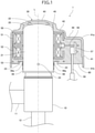
- Fig. 1 is a front view of a motor-operated valve including a stator unit according to an embodiment of the present invention.
- the stator unit is viewed in section.
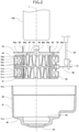
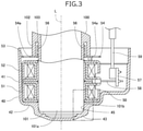
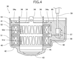
- Figs. 2 to 4 illustrate a method for manufacturing the stator unit illustrated in Fig. 1 . More specifically, Figs. 2 to 4 respectively illustrate a state in which the stator unit is disassembled, a state in which the stator unit is assembled, and a state in which the stator unit is in finished form.
- a cover, a stator, and a mold are viewed in section.
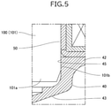
- Fig. 5 is an enlarged sectional view of the region enclosed with a dash-dot-dot line in Fig. 3 .
- a motor-operated valve 1 includes a valve main body 10, a can 20, and a stator unit 30.
- expressions "upper” and “lower” herein refer to the positional relationship in the top-bottom direction in Fig. 1 .
- the valve main body 10 has a hollow cylindrical shape with a bottom.
- the valve main body 10 includes a valve chamber and a valve port communicating with the valve chamber.
- a first conduit 11 and a second conduit 12 are fixed to the valve main body 10 by brazing.
- the first conduit 11 is connected to the valve chamber.
- the second conduit 12 is connected to the valve port.
- the valve chamber is provided with a valve element (not illustrated) for opening and closing the valve port.
- the can 20 has a hollow cylindrical shape with its upper end closed.
- the can 20 includes a hollow cylindrical portion 21 and a ceiling portion 22, which are constructed as one piece.
- the valve main body 10 is attached to a lower end of the hollow cylindrical portion 21.
- the hollow cylindrical portion 21 has an external circumferential surface, on which protrusions 23 are arranged.
- the protrusions 23 are each hemispherical.
- Four protrusions 23 are arranged at 90° intervals on the external circumferential surface of the hollow cylindrical portion 21.
- the ceiling portion 22 is dome-shaped.
- the ceiling portion 22 is contiguous with an upper end of the hollow cylindrical portion 21.
- the upper end of the hollow cylindrical portion 21 is closed by the ceiling portion 22.
- a rotor (not illustrated) is disposed within the can 20.
- the rotor and the stator unit 30 constitute a stepping motor.
- the valve main body 10 is made of stainless steel or brass.
- the can 20 is made of stainless steel.
- the stator unit 30 is disposed on the outside of the can 20.
- the stator unit 30 includes a cover 40, a stator 50, and a mold 60.
- the cover 40 is made of synthetic resin.
- the cover 40 is in the shape of a cap.
- the cover 40 includes a circumferential wall portion 41 and an upper-end wall portion 42, which are constructed as one piece.
- the circumferential wall portion 41 is larger than the contour of the stator 50.
- the stator 50 is disposed on the inner side with respect to the circumferential wall portion 41, with a space left between the stator 50 and the circumferential wall portion 41.
- the upper-end wall portion 42 is contiguous with an upper end 41a (an end) of the circumferential wall portion 41.
- the upper-end wall portion 42 has a dome portion 43.
- the dome portion 43 is at an area in the upper-end wall portion 42 facing the can 20 in the top-bottom direction.
- the upper-end wall portion 42 and the can 20 face each other along a circumference, from which the dome portion 43 protrudes upward.
- the dome portion 43 may have a top part having an opening.
- the dome portion 43 has an inner surface including a circumferential surface 45, which faces inward.
- the diameter of the circumferential surface 45 is equal to the outside diameter of the can 20.
- the diameter of the circumferential surface 45 is not limited to a particular value. It is only required that the diameter of the circumferential surface 45 be equal to or smaller than the inside diameter of the stator 50.
- the diameter of the region defined by the circumferential surface 45 is equal to the outside diameter of the can 20.
- the circumferential surface 45 has a height of 5 mm; that is, the circumferential surface 45 is 5 millimeters long along an axis L.
- the circumferential surface 45 preferably has a height of 1 to 10 mm.
- the diameter of the region defined by the circumferential surface 45 is not limited to a particular value. It is only required that the diameter of the region defined by the circumferential surface 45 be equal to or smaller than the inside diameter of the stator 50.
- the cover 40 is made of rigid resin, such as polybutylene terephthalate (PBT) (coefficient of linear expansion: 2.5 ⁇ 10 -5 /°C) or polyphenylene ether (PPE) (coefficient of linear expansion: 6.6 ⁇ 10 -5 /°C).
- PBT polybutylene terephthalate
- PPE polyphenylene ether
- the stator 50 has a hollow cylindrical shape.
- the stator 50 includes a first stator 51, a second stator 52, a fastening member 53, and a lead wire connection section 57.
- the first stator 51, the second stator 52, and the fastening member 53 are aligned in the top-bottom direction on the drawing plane (i.e., along the axis L).
- the first stator 51 includes metal components such as a yoke 51a, a bobbin 51b, and a coil 51c.
- the coil 51c in the yoke 51a is made of a coil wire wound around the bobbin 51b.
- the yoke 51a includes pole teeth 51d, which are claw poles.
- the pole teeth 51d include downward-pointing pole teeth and upward-pointing pole teeth. Tips (tapered tip portions) of the downward-pointing pole teeth face downward, and tips (tapered tip portions) of the upward-pointing pole teeth face upward.
- the downward-pointing teeth and the upward-pointing teeth are alternately arranged in the circumferential direction.
- the second stator 52 is structurally similar to the first stator 51. More specifically, the second stator 52 includes metal components such as a yoke 52a, a bobbin 52b, a coil 52c, and pole teeth 52d.
- the inside diameter of the first stator 51 and the inside diameter of the second stator 52 are each equal to the outside diameter of the can 20.
- the inside diameter of the first stator 51 and the second stator 52 are each equal to the diameter of the circumferential surface 45 of the cover 40.
- the fastening member 53 includes a flat plate portion 54, connecting tabs 55, and holding tabs 56.
- the flat plate portion 54 has an annular shape.
- the fastening member 53 is formed by using the following procedure: stamping out the flat plate portion 54, the connecting tabs 55, and the holding tabs 56 from a metal sheet; folding the connecting tabs 55 in one direction in such a manner that each connecting tab 55 and the flat plate portion 54 form a right angle; and folding the holding tabs 56 in the opposite direction in such a manner that each holding tab 56 and the flat plate portion 54 form a right angle.
- the flat plate portion 54 has through-holes 54a.
- the connecting tabs 55 are welded to the yoke 52a of the second stator 52.
- the first stator 51, the second stator 52, and the fastening member 53 have coincident axes.
- the fastening member 53 in this embodiment includes four holding tabs 56.
- the holding tabs 56 are disposed so as to correspond to the respective protrusions 23 of the can 20.
- the distance between two holding tabs 56 facing each other in the radial direction of the stator 50 is equal to the outside diameter of the can 20.
- the can 20 is inserted into the stator 50 such that inward-facing surfaces of the holding tabs 56 come into contact with an external circumferential surface of the can 20.
- the holding tabs 56 each have a holding hole 56a. The protrusions 23 are caught in the respective holding holes 56a such that the can 20 and the stator unit 30 are held in place.
- the lead wire connection section 57 is a substrate connected to a tip of a coil terminal pin 58, which extends from the stator 50 in a direction orthogonal to the axis L.
- the lead wire connection section 57 is connected with a lead wire 59.
- the inside diameter of the stator 50 or, more specifically, the inside diameter of each of the first stator 51 and the second stator 52 is equal to the diameter of the region defined by the circumferential surface 45 of the cover 40.
- the inside of the stator 50 is filled with the mold 60. More specifically, the inside of the first stator 51, the inside of the second stator 52, the space between the second stator 52 and the flat plate portion 54, and the through-holes 54a of the flat plate portion 54 are filled with the mold 60. The flat plate portion 54 is embedded in the mold 60. The space between the cover 40 and the stator 50 is also filled with the mold 60.
- the mold 60 is made of highly flexible resin, such as urethane, epoxy, or silicone.
- the highly flexible resin is hereinafter referred to as filling resin.
- the filling resin used in this embodiment is thermoset urethane.
- the valve main body 10, the can 20, the circumferential surface 45 of the cover 40, and the stator 50 (i.e., the first stator 51, the second stator 52, and the fastening member 53) included in the motor-operated valve 1 each have a central axis that coincides with the axis L.
- the following describes a mandrel 100, which is used to manufacture the stator unit 30 of the motor-operated valve 1 described above.
- the mandrel 100 is a jig having a hollow cylindrical shape. Alternatively, the mandrel 100 may have a solid cylindrical shape.
- the mandrel 100 is made of synthetic resin.
- the mandrel 100 is formed by injection molding. The coefficient of linear expansion of the synthetic resin that is the material of the mandrel 100 is higher than the coefficient of linear expansion of the material of the cover 40.
- the mandrel 100 is made of rigid resin, such as polytetrafluoroethylene (PTFE) (coefficient of linear expansion: 10 ⁇ 10 -5 /°C), polystyrene (PS) (coefficient of linear expansion: 5.0 to 8.3 ⁇ 10 -5 /°C), or polyacetal (POM) (coefficient of linear expansion: 3.3 to 7.5 ⁇ 10 -5 /°C).
- PTFE polytetrafluoroethylene
- PS polystyrene
- POM polyacetal
- the mandrel 100 may be made of metal.
- the mandrel 100 includes a trunk portion 101 and a stator-holding portion 102.
- the trunk portion 101 has a hollow cylindrical shape.
- the outside diameter of the trunk portion 101 at room temperature is equal to or slightly smaller than the diameter of the circumferential surface 45 of the cover 40.
- the outside diameter of the trunk portion 101 at room temperature is equal to or slightly smaller than the diameter of the region defined by the circumferential surface 45 of the cover 40.
- the outside diameter of the trunk portion 101 is substantially equal to the outside diameter of the can 20.
- a tip 101a of the trunk portion 101 is placed in the region defined by the circumferential surface 45.
- the stator-holding portion 102 is contiguous with the trunk portion 101.
- the stator-holding portion 102 has a hollow cylindrical shape.
- the outside diameter of the stator-holding portion 102 is greater than the outside diameter of the trunk portion 101.
- a slit 103 annularly extends between the stator-holding portion 102 and the trunk portion 101.
- the mandrel 100 is inserted into the stator 50 such that the inward-facing surfaces of the holding tabs 56 come into contact with an external circumferential surface 101b of the trunk portion 101 of the mandrel 100, and the holding tabs 56 are received in the slits 103 (see Fig. 3 ).
- stator unit 30 of the motor-operated valve 1 The following describes a method for manufacturing the stator unit 30 of the motor-operated valve 1 with reference to Figs. 2 to 5 .
- the cover 40 is placed in a roomtemperature atmosphere in such a manner that a lower end 41b (another end) of the circumferential wall portion 41 faces upward.
- the stator 50 is then placed in the cover 40 in such a manner that the first stator 51 is in contact with the upper-end wall portion 42.
- the trunk portion 101 of the mandrel 100 is inserted into the stator 50.
- the mandrel 100 is placed as illustrated in Fig. 3 . More specifically, the tip 101a of the trunk portion 101 is slid into the dome portion 43 of the cover 40 such that the external circumferential surface 101b of the trunk portion 101 and the circumferential surface 45 face each other in the direction orthogonal to the axis L.
- the tip 101a is placed in the region defined by the circumferential surface 45.
- the holding tabs 56 of the stator 50 are in contact with the trunk portion 101, and each holding tab 56 is located on the inner side of the slit 103 provided in the mandrel 100.
- the stator 50 and the mandrel 100 held in place have coincident axes.
- the stator-holding portion 102 of the mandrel 100 is in contact with the flat plate portion 54.
- the cover 40, the stator 50, and the mandrel 100 assembled to each other are heated.
- the coefficient of linear expansion of the mandrel 100 is higher than the coefficient of linear expansion of the cover 40. Accordingly, the amount of change in the outside diameter of the mandrel 100 is greater than the amount of change in the diameter of the region defined by the circumferential surface 45 of the cover 40. Consequently, the external circumferential surface 101b at the tip 101a of the mandrel 100 and the circumferential surface 45 come into contact with each other along the entire circumference.
- the height of a contact portion where the external circumferential surface 101b and the circumferential surface 45 are in contact with each other is 5 mm.
- the length of fit is preferably equal to or more than 0.2 mm.
- urethane in liquid form is then poured into the cover 40 so as to flow into the stator 50 and the space between the cover 40 and the stator 50.
- the mold 60 is obtained by setting of urethane.
- the cover 40, the stator 50, and the mandrel 100 then cool to room temperature. Subsequently, the mandrel 100 is pulled out of the stator 50.
- the stator unit 30 obtained by this process is in finished form.
- the stator unit 30 included in the motor-operated valve 1 in this embodiment has been described so far.
- the inner surface of the dome portion 43 on the upper-end wall portion 42 of the cover 40 includes the circumferential surface 45, which faces inward.
- the axis of the region defined by the circumferential surface 45 coincides with the axis of stator 50.
- the diameter of the region defined by the circumferential surface 45 is equal to the inside diameter of the stator 50.
- the circumferential surface 45 is useful in manufacturing the stator unit 30.
- the stator unit 30 is manufactured by using the procedure including: (1) inserting, into the stator 50, the mandrel 100 having a coefficient of linear expansion higher than a coefficient of linear expansion of the cover 40; (2) placing the mandrel 100 in such a manner that the external circumferential surface 101b at the tip 101a of the mandrel 100 faces the circumferential surface 45; and (3) heating the cover 40, the stator 50, and the mandrel 100 in such a manner that the external circumferential surface 101b at the tip 101a of the mandrel 100 and the circumferential surface 45 come into contact with each other along the entire circumference.
- the circumferential surface 45 of the stator unit 30 has a height of 5 mm. Thus, the mandrel 100 is more reliably fixed to the cover 40.
- the circumferential surface 45 preferably has a height of 1 to 10 mm. If the height of the circumferential surface 45 is greater than 10 mm, the stator unit 30 would be large in size.
- stator-holding portion 102 In a state in which the external circumferential surface 101b of the mandrel 100 is in contact with the circumferential surface 45, the stator-holding portion 102 is in contact with the stator 50 in such a way as to restrict the movement of the stator 50 along the axis L.
- This structure enables the stator 50 to be held between the cover 40 and the stator-holding portion 102.
- Figs. 6 to 8 illustrate a stator unit 30A, which is a first modification of the stator unit 30 described above.
- the stator unit 30A includes the cover 40, a stator 50A, and the mold 60.
- D1 is greater than D2, where D1 denotes the inside diameter of the stator 50A, and D2 denotes the diameter of the region defined by the circumferential surface 45 of the cover 40. D2 also denotes the diameter of the circumferential surface 45 of the cover 40.
- the outside diameter of the trunk portion 101 of the mandrel 100 at room temperature is equal to or slightly smaller than the diameter of the region defined by the circumferential surface 45 of the cover 40.
- the mandrel 100 is inserted into the stator 50A such that a clearance K1 is left between the stator 50A and the mandrel 100, as illustrated in Fig. 8 .
- stator unit 30A At the time of manufacturing of the stator unit 30A, urethane in liquid form flows into the clearance K1 such that an internal circumferential surface of the stator 50A is covered with urethane. Consequently, the internal circumferential surface of the stator 50A included in the stator unit 30A is covered with the mold 60. Thus, the stator 50A (the pole teeth 51d and the pole teeth 52d) is not exposed, as illustrated in Fig. 7 .
- the stator unit 30A is rendered more highly waterproof accordingly.
- the mold 60 absorbs shock caused by vibrations, thus eliminating or reducing abnormal sounds, out-of-step in the stepping motor, and the possibility that the can 20 will become scratched. This structure prevents or retards electrolytic corrosion of the can 20 and the stator 50A.
- Figs. 9 to 11 illustrate a stator unit 30B, which is a second modification of the stator unit 30 described above.
- the stator unit 30B includes a cover 40B, a stator 50B, and the mold 60.
- the cover 40B includes a rib 44B, which has an annular shape and protrudes from an inner surface of a dome portion 43B along the axis L.
- the rib 44B has a circumferential surface 46B, which faces outward.
- the circumferential surface 46B is an external circumferential surface of the rib 44B.
- the circumferential surface 46B has a height of 2 mm.
- the circumferential surface 46B preferably has a height of 1 to 10 mm.
- the diameter of the circumferential surface 46B is smaller than the inside diameter of the stator 50B.
- the diameter of the region defined by the circumferential surface 46B is smaller than the inside diameter of the stator 50B.
- the dome portion 43B has a circumferential surface 45B, which faces inward.
- the diameter of the circumferential surface 45B is equal to the inside diameter of the stator 50B.
- the diameter of the region defined by the circumferential surface 45B is equal to the inside diameter of the stator 50B.
- the inside diameter of the trunk portion 101 of the mandrel 100 at room temperature is equal to or slightly greater than the diameter of the circumferential surface 46B.
- the inside diameter of the trunk portion 101 of the mandrel 100 at room temperature is equal to or slightly greater than the diameter of the region defined by the circumferential surface 46B.
- the diameter of the circumferential surface 45B and the inside diameter of the stator 50B are each greater than the outside diameter of the trunk portion 101.
- the diameter of the region defined by the circumferential surface 45B and the inside diameter of the stator 50B are each greater than the outside diameter of the trunk portion 101.
- the tip 101a of the trunk portion 101 is placed in the region defined by the circumferential surface 45B.
- the axes of the regions defined respectively by the circumferential surfaces 45B and 46B coincide with the axis of the stator 50B.
- the stator unit 30B is manufactured by using the procedure including: (1) inserting, into the stator 50B, the mandrel 100 having a coefficient of linear expansion lower than a coefficient of linear expansion of the cover 40B; (2) placing the mandrel 100 in such a manner that an internal circumferential surface 101c at the tip 101a of the mandrel 100 faces the circumferential surface 46B; and (3) heating the cover 40B, the stator 50B, and the mandrel 100 in such a manner that the internal circumferential surface 101c at the tip 101a of the mandrel 100 and the circumferential surface 46B come into contact with each other along the entire circumference.
- the coefficient of linear expansion of the mandrel 100 is lower than the coefficient of linear expansion of the cover 40B. Accordingly, the amount of change in the diameter of the region defined by the circumferential surface 46B of the cover 40B is greater than the amount of change in the inside diameter of the mandrel 100. Consequently, the internal circumferential surface 101c at the tip 101a of the mandrel 100 and the circumferential surface 46B come into contact with each other along the entire circumference.
- the mandrel 100 is fixed to the cover 40B in such a manner that the region defined by the circumferential surface 46B and the mandrel 100 have coincident axes.
- the inside diameter of the stator 50B included in the stator unit 30B and the diameter of the region defined by the circumferential surface 45B are each greater than the outside diameter of the trunk portion 101 of the mandrel 100.
- the mandrel 100 is inserted into the stator 50B such that a clearance K2 is left between the stator 50B and the mandrel 100 and between the circumferential surface 45B and the mandrel 100, as illustrated in Fig. 11 .
- urethane in liquid form flows into the clearance K2 such that an internal circumferential surface of the stator 50B is covered with urethane.
- stator 50B (the pole teeth 51d and the pole teeth 52d) is not exposed, as illustrated in Fig. 10 .
- the stator unit 30B is rendered more highly waterproof accordingly.
- the mold 60 comes into contact with the can 20; that is, the stator 50B is kept from contact with the can 20.
- the mold 60 absorbs shock caused by vibrations, thus eliminating or reducing abnormal sounds, out-of-step in the stepping motor, and the possibility that the can 20 will become scratched. This structure prevents or retards electrolytic corrosion of the can 20 and the stator 50B.
Landscapes
- Engineering & Computer Science (AREA)
- Power Engineering (AREA)
- Manufacturing & Machinery (AREA)
- General Engineering & Computer Science (AREA)
- Mechanical Engineering (AREA)
- Manufacture Of Motors, Generators (AREA)
- Electrically Driven Valve-Operating Means (AREA)
- Motor Or Generator Frames (AREA)
- Insulation, Fastening Of Motor, Generator Windings (AREA)
- Connection Of Motors, Electrical Generators, Mechanical Devices, And The Like (AREA)
Abstract
Description
- The present invention relates to a stator unit for use in a motor-operated valve, to a motor-operated valve including a stator unit, and to a method for manufacturing a stator unit.
- Examples of stator units according to the related art are disclosed in
Japanese Unexamined Patent Application Publication No. 2001-343085 Japanese Unexamined Patent Application Publication No. 2006-20480 - The stator unit (coil for a motor-operated valve) disclosed in Patent Literature 1 includes a cover and a stator. The cover is in the shape of a cap. The stator has a hollow cylindrical shape. The stator includes a metal component, a coil wire, and a mold made of rigid resin. The peripheral part of the body constituted of the metal component and the coil wire is covered with the mold. The stator is accommodated in the cover. The space between the cover and the stator is filled with filling resin that is flexible.
- The process for manufacturing such a stator unit may include the steps of: (1) forming a stator by insert molding; (2) placing the stator in a cover; (3) inserting a mandrel (jig) into a stator to position the cover and the stator; (4) clamping the mandrel and the cover; (5) pouring filling resin in liquid form into the cover with its lower end facing upward; and (6) removing the mandrel after the filling resin sets. The stator unit obtained by this process is in finished form.
- Likewise, the stator unit (electromagnetic actuator) disclosed in Patent Literature 2 includes a cover and a stator. The space between the cover and the stator is filled with filling resin.
- The stator described in Patent Literature 2 is formed by insert molding in such a manner that a gap on an internal circumferential surface of a metal component is filled with rigid resin. The stator includes an annular rib. The rib fits into an annular groove in an upper-end wall portion of the cover. When filling resin in liquid form is poured into the cover, the rib in the groove keeps the filling resin from leaking into the stator. This structure eliminates the need for a jig such as a mandrel during the manufacturing of a stator unit.
- It is required that the stator included in the stator unit disclosed in Patent Literature 1 and the stator included in the stator unit disclosed in Patent Literature 2 be both formed by insert molding. More man-hours are needed to manufacture such a stator unit, thus leading to an increase in the cost of manufacturing. The need of clamping the mandrel and the cover during the manufacturing of the stator unit disclosed in Patent Literature 1 causes a further increase in the cost of manufacturing.
- The stator unit disclosed in Patent Literature 2 eliminates the need for a jig. To that end, the gap on the internal circumferential surface of the metal component of the stator is filled with rigid resin. Unlike the case with filling resin, cracks are likely to form between the rigid resin and the metal component. Thus, this structure may fail to prevent moisture from entering the stator.
- It is an object of the present invention to provide a stator unit and a motor-operated valve that are highly waterproof and enable a reduction in the cost of manufacturing. It is another object of the present invention to provide a method for manufacturing the stator unit.
- To that end, an aspect of the present invention is directed to a stator unit. The stator unit includes a cover, a stator, and a mold. The cover includes a circumferential wall portion and an end wall portion contiguous with an end of the circumferential wall portion. The stator is accommodated in the cover and has a hollow cylindrical shape. The mold is made of filling resin with which the inside of the stator and the space between the stator and the cover are filled. The end wall portion has an inner surface including a circumferential surface that faces inward or outward. The circumferential surface defines a region having an axis that coincides with an axis of the stator. The region defined by the circumferential surface has a diameter equal to or smaller than the inside diameter of the stator.
- The circumferential surface preferably has a height of 1 to 10 mm.
- The stator preferably has an internal circumferential surface covered with the mold.
- Another aspect of the present invention is directed to a motor-operated valve. The motor-operated valve includes a valve main body, a can, and a stator unit. The can is attached to the valve main body. The stator unit is mounted on the outside of the can. The stator unit is the stator unit described above.
- To attain the aforementioned objective, still another aspect of the invention is directed to a method for manufacturing a stator unit. The stator unit includes a cover and a stator having a hollow cylindrical shape. The cover includes a circumferential wall portion and an end wall portion contiguous with an end of the circumferential wall portion. The end wall portion has an inner surface including a circumferential surface that faces inward. The circumferential surface defines a region having an axis that coincides with an axis of the stator. The region defined by the circumferential surface has a diameter equal to or smaller than the inside diameter of the stator. The method includes: placing the stator in the cover; inserting, into the stator, a jig having a coefficient of linear expansion higher than a coefficient of linear expansion of the cover and having a hollow cylindrical shape or a solid cylindrical shape; placing the jig in such a manner that an external circumferential surface at a tip of the jig faces the circumferential surface; heating the cover and the jig in such a manner that the external circumferential surface at the tip of the jig and the circumferential surface come into contact with each other along an entire circumference; and pouring filling resin in liquid form in a state in which another end of the circumferential wall portion of the cover faces upward in such a manner that the inside of the stator and the space between the stator and the cover are filled with the filling resin.
- To attain the aforementioned objective, still another aspect of the invention is directed to a method for manufacturing a stator unit. The stator unit includes a cover and a stator having a hollow cylindrical shape. The cover includes a circumferential wall portion and an end wall portion contiguous with an end of the circumferential wall portion. The end wall portion has an inner surface including a circumferential surface that faces outward. The circumferential surface defines a region having an axis that coincides with an axis of the stator. The region defined by the circumferential surface has a diameter equal to or smaller than the inside diameter of the stator. The method includes: placing the stator in the cover; inserting, into the stator, a jig having a coefficient of linear expansion lower than a coefficient of linear expansion of the cover and having a hollow cylindrical shape; placing the jig in such a manner that an internal circumferential surface at a tip of the jig faces the circumferential surface; heating the cover and the jig in such a manner that the internal circumferential surface at the tip of the jig and the circumferential surface come into contact with each other along an entire circumference; and pouring filling resin in liquid form in a state in which another end of the circumferential wall portion of the cover faces upward in such a manner that the inside of the stator and the space between the stator and the cover are filled with the filling resin.
- The stator preferably has an inside diameter greater than the outside diameter of the jig.
- The jig preferably includes a stator-holding portion that is in contact with the stator in such a way as to restrict movement of the stator along an axis of the stator in a state in which the jig is in contact with the circumferential surface.
- The circumferential surface of the inner surface of the end wall portion of the cover includes faces inward or outward. The axis of the region defined by the circumferential surface coincides with the axis of the stator. The diameter of the region defined by the circumferential surface is equal to or smaller than the inside diameter of the stator. The circumferential surface is useful in manufacturing the stator unit. More specifically, the aforementioned methods for manufacturing a stator unit each include: (1-a) inserting, into a stator, a jig having an outward-facing circumferential surface (external circumferential surface) that can come into contact with an inward-facing circumferential surface of a cover and having a coefficient of linear expansion higher than a coefficient of linear expansion of the cover or (1-b)inserting, into a stator, a jig having an inward-facing circumferential surface (internal circumferential surface) that can come into contact with an outward-facing circumferential surface of a cover and having a coefficient of linear expansion lower than a coefficient of linear expansion of the cover; (2) placing the jig in such a manner that the (external or internal) circumferential surface of the jig faces the circumferential surface of the cover; and (3) heating the cover and the jig in such a manner that the circumferential surface of the jig and the circumferential surface of the cover come into contact with each other along an entire circumference. In this way, the (external or internal) circumferential surface of the jig and the circumferential surface of the cover come into close contact with each other, and the jig is fixed to the cover without the need for a clamp or the like. With the jig being fixed to the cover, filling resin in liquid form is poured into the cover. Consequently, the inside of the stator and the space between the stator and the cover are filled with the filling resin. This procedure eliminates the need for forming the stator by insert molding and the need for clamping, thus enabling a reduction in the cost of manufacturing the stator unit. The inside of the stator is filled with the filling resin, and the stator unit is thus rendered highly waterproof.
-
-
Fig. 1 illustrates a motor-operated valve including a stator unit according to an embodiment of the present invention. -
Fig. 2 illustrates a method for manufacturing the stator unit illustrated inFig. 1 in a state in which the stator unit is disassembled. -
Fig. 3 illustrates the method for manufacturing the stator unit illustrated inFig. 1 in a state in which the stator unit is assembled. -
Fig. 4 illustrates the method for manufacturing the stator unit illustrated inFig. 1 in a state in which the stator unit is in finished form. -
Fig. 5 is an enlarged sectional view of the region enclosed with a dash-dot-dot line inFig. 3 . -
Fig. 6 illustrates a method for manufacturing a stator unit that is a first modification of the stator unit illustrated inFig. 1 in a state in which the stator unit is assembled. -
Fig. 7 illustrates the method for manufacturing the stator unit illustrated inFig. 6 in a state in which the stator unit is in finished form. -
Fig. 8 is an enlarged sectional view of the region enclosed with a dash-dot-dot line inFig. 6 . -
Fig. 9 illustrates a method for manufacturing a stator unit that is a second modification of the stator unit illustrated inFig. 1 in a state in which the stator unit is assembled. -
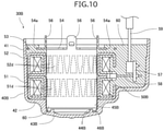
Fig. 10 illustrates the method for manufacturing the stator unit illustrated inFig. 9 in a state in which the stator unit is in finished form. -
Fig. 11 is an enlarged sectional view of the region enclosed with a dash-dot-dot line inFig. 9 . - Hereinafter, a motor-operated valve according to an embodiment of the present invention will be described with reference to
Figs. 1 to 5 . -
Fig. 1 is a front view of a motor-operated valve including a stator unit according to an embodiment of the present invention. InFig. 1 , the stator unit is viewed in section.Figs. 2 to 4 illustrate a method for manufacturing the stator unit illustrated inFig. 1 . More specifically,Figs. 2 to 4 respectively illustrate a state in which the stator unit is disassembled, a state in which the stator unit is assembled, and a state in which the stator unit is in finished form. InFigs. 2 to 4 , a cover, a stator, and a mold are viewed in section.Fig. 5 is an enlarged sectional view of the region enclosed with a dash-dot-dot line inFig. 3 . - Referring to
Fig. 1 , a motor-operated valve 1 includes a valvemain body 10, a can 20, and astator unit 30. Unless otherwise specified, expressions "upper" and "lower" herein refer to the positional relationship in the top-bottom direction inFig. 1 . - The valve
main body 10 has a hollow cylindrical shape with a bottom. The valvemain body 10 includes a valve chamber and a valve port communicating with the valve chamber. Afirst conduit 11 and asecond conduit 12 are fixed to the valvemain body 10 by brazing. Thefirst conduit 11 is connected to the valve chamber. Thesecond conduit 12 is connected to the valve port. The valve chamber is provided with a valve element (not illustrated) for opening and closing the valve port. - The can 20 has a hollow cylindrical shape with its upper end closed. The can 20 includes a hollow
cylindrical portion 21 and a ceiling portion 22, which are constructed as one piece. The valvemain body 10 is attached to a lower end of the hollowcylindrical portion 21. The hollowcylindrical portion 21 has an external circumferential surface, on whichprotrusions 23 are arranged. Theprotrusions 23 are each hemispherical. Fourprotrusions 23 are arranged at 90° intervals on the external circumferential surface of the hollowcylindrical portion 21. The ceiling portion 22 is dome-shaped. The ceiling portion 22 is contiguous with an upper end of the hollowcylindrical portion 21. The upper end of the hollowcylindrical portion 21 is closed by the ceiling portion 22. A rotor (not illustrated) is disposed within the can 20. The rotor and thestator unit 30 constitute a stepping motor. The valvemain body 10 is made of stainless steel or brass. The can 20 is made of stainless steel. - The
stator unit 30 is disposed on the outside of the can 20. Thestator unit 30 includes acover 40, astator 50, and amold 60. - The
cover 40 is made of synthetic resin. Thecover 40 is in the shape of a cap. Thecover 40 includes acircumferential wall portion 41 and an upper-end wall portion 42, which are constructed as one piece. Thecircumferential wall portion 41 is larger than the contour of thestator 50. Thestator 50 is disposed on the inner side with respect to thecircumferential wall portion 41, with a space left between thestator 50 and thecircumferential wall portion 41. The upper-end wall portion 42 is contiguous with anupper end 41a (an end) of thecircumferential wall portion 41. The upper-end wall portion 42 has adome portion 43. Thedome portion 43 is at an area in the upper-end wall portion 42 facing the can 20 in the top-bottom direction. The upper-end wall portion 42 and the can 20 face each other along a circumference, from which thedome portion 43 protrudes upward. Thedome portion 43 may have a top part having an opening. Thedome portion 43 has an inner surface including acircumferential surface 45, which faces inward. The diameter of thecircumferential surface 45 is equal to the outside diameter of the can 20. The diameter of thecircumferential surface 45 is not limited to a particular value. It is only required that the diameter of thecircumferential surface 45 be equal to or smaller than the inside diameter of thestator 50. The diameter of the region defined by thecircumferential surface 45 is equal to the outside diameter of the can 20. In this embodiment, thecircumferential surface 45 has a height of 5 mm; that is, thecircumferential surface 45 is 5 millimeters long along an axis L. Thecircumferential surface 45 preferably has a height of 1 to 10 mm. The diameter of the region defined by thecircumferential surface 45 is not limited to a particular value. It is only required that the diameter of the region defined by thecircumferential surface 45 be equal to or smaller than the inside diameter of thestator 50. - The
cover 40 is made of rigid resin, such as polybutylene terephthalate (PBT) (coefficient of linear expansion: 2.5 × 10⁻⁵/°C) or polyphenylene ether (PPE) (coefficient of linear expansion: 6.6 × 10⁻⁵/°C). - The
stator 50 has a hollow cylindrical shape. Thestator 50 includes afirst stator 51, asecond stator 52, afastening member 53, and a leadwire connection section 57. Thefirst stator 51, thesecond stator 52, and thefastening member 53 are aligned in the top-bottom direction on the drawing plane (i.e., along the axis L). - The
first stator 51 includes metal components such as ayoke 51a, abobbin 51b, and acoil 51c. Thecoil 51c in theyoke 51a is made of a coil wire wound around thebobbin 51b. Theyoke 51a includespole teeth 51d, which are claw poles. Thepole teeth 51d include downward-pointing pole teeth and upward-pointing pole teeth. Tips (tapered tip portions) of the downward-pointing pole teeth face downward, and tips (tapered tip portions) of the upward-pointing pole teeth face upward. The downward-pointing teeth and the upward-pointing teeth are alternately arranged in the circumferential direction. - The
second stator 52 is structurally similar to thefirst stator 51. More specifically, thesecond stator 52 includes metal components such as ayoke 52a, abobbin 52b, acoil 52c, andpole teeth 52d. The inside diameter of thefirst stator 51 and the inside diameter of thesecond stator 52 are each equal to the outside diameter of the can 20. The inside diameter of thefirst stator 51 and thesecond stator 52 are each equal to the diameter of thecircumferential surface 45 of thecover 40. - The
fastening member 53 includes aflat plate portion 54, connectingtabs 55, and holdingtabs 56. Theflat plate portion 54 has an annular shape. Thefastening member 53 is formed by using the following procedure: stamping out theflat plate portion 54, the connectingtabs 55, and the holdingtabs 56 from a metal sheet; folding the connectingtabs 55 in one direction in such a manner that each connectingtab 55 and theflat plate portion 54 form a right angle; and folding the holdingtabs 56 in the opposite direction in such a manner that each holdingtab 56 and theflat plate portion 54 form a right angle. Theflat plate portion 54 has through-holes 54a. The connectingtabs 55 are welded to theyoke 52a of thesecond stator 52. Thefirst stator 51, thesecond stator 52, and thefastening member 53 have coincident axes. - The
fastening member 53 in this embodiment includes four holdingtabs 56. The holdingtabs 56 are disposed so as to correspond to therespective protrusions 23 of the can 20. The distance between two holdingtabs 56 facing each other in the radial direction of thestator 50 is equal to the outside diameter of the can 20. The can 20 is inserted into thestator 50 such that inward-facing surfaces of the holdingtabs 56 come into contact with an external circumferential surface of the can 20. The holdingtabs 56 each have a holdinghole 56a. Theprotrusions 23 are caught in the respective holdingholes 56a such that the can 20 and thestator unit 30 are held in place. - The lead
wire connection section 57 is a substrate connected to a tip of acoil terminal pin 58, which extends from thestator 50 in a direction orthogonal to the axis L. The leadwire connection section 57 is connected with alead wire 59. - In this embodiment, the inside diameter of the
stator 50 or, more specifically, the inside diameter of each of thefirst stator 51 and thesecond stator 52 is equal to the diameter of the region defined by thecircumferential surface 45 of thecover 40. - The inside of the
stator 50 is filled with themold 60. More specifically, the inside of thefirst stator 51, the inside of thesecond stator 52, the space between thesecond stator 52 and theflat plate portion 54, and the through-holes 54a of theflat plate portion 54 are filled with themold 60. Theflat plate portion 54 is embedded in themold 60. The space between thecover 40 and thestator 50 is also filled with themold 60. - The
mold 60 is made of highly flexible resin, such as urethane, epoxy, or silicone. The highly flexible resin is hereinafter referred to as filling resin. The filling resin used in this embodiment is thermoset urethane. - The valve
main body 10, the can 20, thecircumferential surface 45 of thecover 40, and the stator 50 (i.e., thefirst stator 51, thesecond stator 52, and the fastening member 53) included in the motor-operated valve 1 each have a central axis that coincides with the axis L. - The following describes a
mandrel 100, which is used to manufacture thestator unit 30 of the motor-operated valve 1 described above. - The
mandrel 100 is a jig having a hollow cylindrical shape. Alternatively, themandrel 100 may have a solid cylindrical shape. Themandrel 100 is made of synthetic resin. Themandrel 100 is formed by injection molding. The coefficient of linear expansion of the synthetic resin that is the material of themandrel 100 is higher than the coefficient of linear expansion of the material of thecover 40. Themandrel 100 is made of rigid resin, such as polytetrafluoroethylene (PTFE) (coefficient of linear expansion: 10 × 10-5/°C), polystyrene (PS) (coefficient of linear expansion: 5.0 to 8.3 × 10⁻⁵/°C), or polyacetal (POM) (coefficient of linear expansion: 3.3 to 7.5 × 10⁻⁵/°C). Alternatively, themandrel 100 may be made of metal. - The
mandrel 100 includes atrunk portion 101 and a stator-holdingportion 102. Thetrunk portion 101 has a hollow cylindrical shape. The outside diameter of thetrunk portion 101 at room temperature is equal to or slightly smaller than the diameter of thecircumferential surface 45 of thecover 40. Thus, the outside diameter of thetrunk portion 101 at room temperature is equal to or slightly smaller than the diameter of the region defined by thecircumferential surface 45 of thecover 40. The outside diameter of thetrunk portion 101 is substantially equal to the outside diameter of the can 20. Atip 101a of thetrunk portion 101 is placed in the region defined by thecircumferential surface 45. The stator-holdingportion 102 is contiguous with thetrunk portion 101. The stator-holdingportion 102 has a hollow cylindrical shape. The outside diameter of the stator-holdingportion 102 is greater than the outside diameter of thetrunk portion 101. Aslit 103 annularly extends between the stator-holdingportion 102 and thetrunk portion 101. Themandrel 100 is inserted into thestator 50 such that the inward-facing surfaces of the holdingtabs 56 come into contact with an externalcircumferential surface 101b of thetrunk portion 101 of themandrel 100, and the holdingtabs 56 are received in the slits 103 (seeFig. 3 ). - The following describes a method for manufacturing the
stator unit 30 of the motor-operated valve 1 with reference toFigs. 2 to 5 . - Referring to
Fig. 2 , thecover 40 is placed in a roomtemperature atmosphere in such a manner that alower end 41b (another end) of thecircumferential wall portion 41 faces upward. Thestator 50 is then placed in thecover 40 in such a manner that thefirst stator 51 is in contact with the upper-end wall portion 42. Subsequently, thetrunk portion 101 of themandrel 100 is inserted into thestator 50. Themandrel 100 is placed as illustrated inFig. 3 . More specifically, thetip 101a of thetrunk portion 101 is slid into thedome portion 43 of thecover 40 such that the externalcircumferential surface 101b of thetrunk portion 101 and thecircumferential surface 45 face each other in the direction orthogonal to the axis L. Thetip 101a is placed in the region defined by thecircumferential surface 45. In this state, the holdingtabs 56 of thestator 50 are in contact with thetrunk portion 101, and each holdingtab 56 is located on the inner side of theslit 103 provided in themandrel 100. Thestator 50 and themandrel 100 held in place have coincident axes. The stator-holdingportion 102 of themandrel 100 is in contact with theflat plate portion 54. - Then, the
cover 40, thestator 50, and themandrel 100 assembled to each other are heated. The coefficient of linear expansion of themandrel 100 is higher than the coefficient of linear expansion of thecover 40. Accordingly, the amount of change in the outside diameter of themandrel 100 is greater than the amount of change in the diameter of the region defined by thecircumferential surface 45 of thecover 40. Consequently, the externalcircumferential surface 101b at thetip 101a of themandrel 100 and thecircumferential surface 45 come into contact with each other along the entire circumference. The height of a contact portion where the externalcircumferential surface 101b and thecircumferential surface 45 are in contact with each other (the length of fit) is 5 mm. The length of fit is preferably equal to or more than 0.2 mm. With the contact portion being provided, themandrel 100 is fixed to thecover 40 in such a manner that the region defined by thecircumferential surface 45 and themandrel 100 have coincident axes. Likewise, themandrel 100 and thestator 50 have coincident axes. Thestator 50 is held between thecover 40 and the stator-holdingportion 102 of themandrel 100. - As the filling resin, urethane in liquid form is then poured into the
cover 40 so as to flow into thestator 50 and the space between thecover 40 and thestator 50. Themold 60 is obtained by setting of urethane. Thecover 40, thestator 50, and themandrel 100 then cool to room temperature. Subsequently, themandrel 100 is pulled out of thestator 50. Thestator unit 30 obtained by this process is in finished form. - The
stator unit 30 included in the motor-operated valve 1 in this embodiment has been described so far. The inner surface of thedome portion 43 on the upper-end wall portion 42 of thecover 40 includes thecircumferential surface 45, which faces inward. The axis of the region defined by thecircumferential surface 45 coincides with the axis ofstator 50. The diameter of the region defined by thecircumferential surface 45 is equal to the inside diameter of thestator 50. Thecircumferential surface 45 is useful in manufacturing thestator unit 30. More specifically, thestator unit 30 is manufactured by using the procedure including: (1) inserting, into thestator 50, themandrel 100 having a coefficient of linear expansion higher than a coefficient of linear expansion of thecover 40; (2) placing themandrel 100 in such a manner that the externalcircumferential surface 101b at thetip 101a of themandrel 100 faces thecircumferential surface 45; and (3) heating thecover 40, thestator 50, and themandrel 100 in such a manner that the externalcircumferential surface 101b at thetip 101a of themandrel 100 and thecircumferential surface 45 come into contact with each other along the entire circumference. In this way, the externalcircumferential surface 101b of themandrel 100 and thecircumferential surface 45 of thecover 40 come into close contact with each other, and themandrel 100 is fixed to thecover 40 without the need for a clamp or the like. With themandrel 100 being fixed to thecover 40, urethane in liquid form is poured into thecover 40 and is consequently formed into themold 60, with which the inside of thestator 50 and the space between thestator 50 and thecover 40 are filled. This procedure eliminates the need for forming thestator 50 by insert molding and the need for clamping, thus enabling a reduction in the cost of manufacturing thestator unit 30. The inside of thestator 50 is filled with urethane, and thestator unit 30 is thus rendered highly waterproof. - The
circumferential surface 45 of thestator unit 30 has a height of 5 mm. Thus, themandrel 100 is more reliably fixed to thecover 40. Thecircumferential surface 45 preferably has a height of 1 to 10 mm. If the height of thecircumferential surface 45 is greater than 10 mm, thestator unit 30 would be large in size. - In a state in which the external
circumferential surface 101b of themandrel 100 is in contact with thecircumferential surface 45, the stator-holdingportion 102 is in contact with thestator 50 in such a way as to restrict the movement of thestator 50 along the axis L. This structure enables thestator 50 to be held between thecover 40 and the stator-holdingportion 102. - The following describes modifications of the
stator unit 30 with reference toFigs. 6 to 11 . Some of the constituent elements of the stator unit according to any one of the following modifications are denoted by the reference signs of the respective constituent elements of the above-described motor-operated valve 1. Unless otherwise specified, each of these constituent elements is identical or substantially identical to the corresponding constituent element of the motor-operated valve 1 in structural respects. -
Figs. 6 to 8 illustrate astator unit 30A, which is a first modification of thestator unit 30 described above. Thestator unit 30A includes thecover 40, astator 50A, and themold 60. - Referring to
Fig. 6 , D1 is greater than D2, where D1 denotes the inside diameter of thestator 50A, and D2 denotes the diameter of the region defined by thecircumferential surface 45 of thecover 40. D2 also denotes the diameter of thecircumferential surface 45 of thecover 40. The outside diameter of thetrunk portion 101 of themandrel 100 at room temperature is equal to or slightly smaller than the diameter of the region defined by thecircumferential surface 45 of thecover 40. Themandrel 100 is inserted into thestator 50A such that a clearance K1 is left between thestator 50A and themandrel 100, as illustrated inFig. 8 . At the time of manufacturing of thestator unit 30A, urethane in liquid form flows into the clearance K1 such that an internal circumferential surface of thestator 50A is covered with urethane. Consequently, the internal circumferential surface of thestator 50A included in thestator unit 30A is covered with themold 60. Thus, thestator 50A (thepole teeth 51d and thepole teeth 52d) is not exposed, as illustrated inFig. 7 . Thestator unit 30A is rendered more highly waterproof accordingly. When the can 20 and thestator unit 30A vibrate, themold 60 comes into contact with the can 20; that is, thestator 50A is kept from contact with the can 20. Themold 60 absorbs shock caused by vibrations, thus eliminating or reducing abnormal sounds, out-of-step in the stepping motor, and the possibility that the can 20 will become scratched. This structure prevents or retards electrolytic corrosion of the can 20 and thestator 50A. -
Figs. 9 to 11 illustrate astator unit 30B, which is a second modification of thestator unit 30 described above. Thestator unit 30B includes acover 40B, astator 50B, and themold 60. - Referring to
Fig. 9 , thecover 40B includes arib 44B, which has an annular shape and protrudes from an inner surface of adome portion 43B along the axis L. Therib 44B has acircumferential surface 46B, which faces outward. Thecircumferential surface 46B is an external circumferential surface of therib 44B. Thecircumferential surface 46B has a height of 2 mm. Thecircumferential surface 46B preferably has a height of 1 to 10 mm. The diameter of thecircumferential surface 46B is smaller than the inside diameter of thestator 50B. Thus, the diameter of the region defined by thecircumferential surface 46B is smaller than the inside diameter of thestator 50B. Thedome portion 43B has acircumferential surface 45B, which faces inward. The diameter of thecircumferential surface 45B is equal to the inside diameter of thestator 50B. Thus, the diameter of the region defined by thecircumferential surface 45B is equal to the inside diameter of thestator 50B. The inside diameter of thetrunk portion 101 of themandrel 100 at room temperature is equal to or slightly greater than the diameter of thecircumferential surface 46B. Thus, the inside diameter of thetrunk portion 101 of themandrel 100 at room temperature is equal to or slightly greater than the diameter of the region defined by thecircumferential surface 46B. The diameter of thecircumferential surface 45B and the inside diameter of thestator 50B are each greater than the outside diameter of thetrunk portion 101. Thus, the diameter of the region defined by thecircumferential surface 45B and the inside diameter of thestator 50B are each greater than the outside diameter of thetrunk portion 101. Thetip 101a of thetrunk portion 101 is placed in the region defined by thecircumferential surface 45B. The axes of the regions defined respectively by thecircumferential surfaces stator 50B. - The
stator unit 30B is manufactured by using the procedure including: (1) inserting, into thestator 50B, themandrel 100 having a coefficient of linear expansion lower than a coefficient of linear expansion of thecover 40B; (2) placing themandrel 100 in such a manner that an internalcircumferential surface 101c at thetip 101a of themandrel 100 faces thecircumferential surface 46B; and (3) heating thecover 40B, thestator 50B, and themandrel 100 in such a manner that the internalcircumferential surface 101c at thetip 101a of themandrel 100 and thecircumferential surface 46B come into contact with each other along the entire circumference. - The coefficient of linear expansion of the
mandrel 100 is lower than the coefficient of linear expansion of thecover 40B. Accordingly, the amount of change in the diameter of the region defined by thecircumferential surface 46B of thecover 40B is greater than the amount of change in the inside diameter of themandrel 100. Consequently, the internalcircumferential surface 101c at thetip 101a of themandrel 100 and thecircumferential surface 46B come into contact with each other along the entire circumference. Themandrel 100 is fixed to thecover 40B in such a manner that the region defined by thecircumferential surface 46B and themandrel 100 have coincident axes. - The inside diameter of the
stator 50B included in thestator unit 30B and the diameter of the region defined by thecircumferential surface 45B are each greater than the outside diameter of thetrunk portion 101 of themandrel 100. Themandrel 100 is inserted into thestator 50B such that a clearance K2 is left between thestator 50B and themandrel 100 and between thecircumferential surface 45B and themandrel 100, as illustrated inFig. 11 . At the time of manufacturing of thestator unit 30B, urethane in liquid form flows into the clearance K2 such that an internal circumferential surface of thestator 50B is covered with urethane. Consequently, the internal circumferential surface of thestator 50B included in thestator unit 30B is covered with themold 60. Thus, thestator 50B (thepole teeth 51d and thepole teeth 52d) is not exposed, as illustrated inFig. 10 . Thestator unit 30B is rendered more highly waterproof accordingly. When the can 20 and thestator unit 30B vibrate, themold 60 comes into contact with the can 20; that is, thestator 50B is kept from contact with the can 20. Themold 60 absorbs shock caused by vibrations, thus eliminating or reducing abnormal sounds, out-of-step in the stepping motor, and the possibility that the can 20 will become scratched. This structure prevents or retards electrolytic corrosion of the can 20 and thestator 50B. - The present invention has been described by way of embodiments, which should not be construed as limiting the scope of the present invention. Those skilled in the art may, as appropriate, modify these embodiments by adding or eliminating constituent elements, by making design changes, or by combining features of the individual embodiments. These modified embodiments fall within the scope of the present invention as long as no contradiction to the spirit of the present invention is involved.
Claims (8)
- A stator unit, comprising:a cover (40, 40B) including a circumferential wall portion (41) and an end wall portion (42) contiguous with an end (41a) of the circumferential wall portion (41);a stator (50, 50A, 50B) accommodated in the cover (40, 40B) and having a hollow cylindrical shape; anda mold (60) made of filling resin with which an inside of the stator (50, 50A, 50B) and a space between the stator (50, 50A, 50B) and the cover (40, 40B) are filled, whereinthe end wall portion (42) has an inner surface including a circumferential surface (45, 46B) that faces inward or outward,the circumferential surface (45, 46B) defines a region having an axis that coincides with an axis of the stator (50, 50A, 50B), andthe region defined by the circumferential surface (45, 46B) has a diameter equal to or smaller than an inside diameter of the stator (50, 50A, 50B).
- The stator unit according to Claim 1, wherein the circumferential surface (45, 46B) has a height of 1 to 10 mm.
- The stator unit according to Claim 1 or 2, wherein the stator (50A, 50B) has an internal circumferential surface covered with the mold (60).
- A motor-operated valve, comprising:a valve main body (10);a can (20) attached to the valve main body (10); anda stator unit (30, 30A, 30B) mounted on an outside of the can (20), whereinthe stator unit (30, 30A, 30B) is the stator unit according to any one of Claims 1 to 3.
- A method for manufacturing a stator unit (30, 30A) that includes a cover (40) and a stator (50, 50A) having a hollow cylindrical shape, the cover (40) including a circumferential wall portion (41) and an end wall portion (42) contiguous with an end (41a) of the circumferential wall portion (41), the end wall portion (42) having an inner surface including a circumferential surface (45) that faces inward, the circumferential surface (45) defining a region having an axis that coincides with an axis of the stator (50, 50A), the region defined by the circumferential surface (45) having a diameter equal to or smaller than an inside diameter of the stator (50, 50A), the method comprising:placing the stator (50, 50A) in the cover (40);inserting, into the stator (50, 50A), a jig (100) having a coefficient of linear expansion higher than a coefficient of linear expansion of the cover (40) and having a hollow cylindrical shape or a solid cylindrical shape;placing the jig (100) in such a manner that an external circumferential surface (101b) at a tip (101a) of the jig (100) faces the circumferential surface (45);heating the cover (40) and the jig (100) in such a manner that the external circumferential surface (101b) at the tip (101a) of the jig (100) and the circumferential surface (45) come into contact with each other along an entire circumference; andpouring filling resin in liquid form in a state in which another end (41b) of the circumferential wall portion (41) of the cover (40) faces upward in such a manner that an inside of the stator (50, 50A) and a space between the stator (50, 50A) and the cover (40) are filled with the filling resin.
- A method for manufacturing a stator unit (30B) that includes a cover (40B) and a stator (50B) having a hollow cylindrical shape, the cover (40B) including a circumferential wall portion (41) and an end wall portion (42) contiguous with an end (41a) of the circumferential wall portion (41), the end wall portion (42) having an inner surface including a circumferential surface (46B) that faces outward, the circumferential surface (46B) defining a region having an axis that coincides with an axis of the stator (50B), the region defined by the circumferential surface (46B) having a diameter equal to or smaller than an inside diameter of the stator (50B), the method comprising:placing the stator (50B) in the cover (40B);inserting, into the stator (50B), a jig (100) having a coefficient of linear expansion lower than a coefficient of linear expansion of the cover (40B) and having a hollow cylindrical shape;placing the jig (100) in such a manner that an internal circumferential surface (101c) at a tip (101a) of the jig (100) faces the circumferential surface (46B);heating the cover (40B) and the jig (100) in such a manner that the internal circumferential surface (101c) at the tip (101a) of the jig (100) and the circumferential surface (46B) come into contact with each other along an entire circumference; andpouring filling resin in liquid form in a state in which another end (41b) of the circumferential wall portion (41) of the cover (40B) faces upward in such a manner that an inside of the stator (50B) and a space between the stator (50B) and the cover (40B) are filled with the filling resin.
- The method for manufacturing the stator unit (30A, 30B) according to Claim 5 or 6, wherein the stator (50A, 50B) has an inside diameter greater than an outside diameter of the jig (100).
- The method for manufacturing the stator unit (30, 30A, 30B) according to any one of Claims 5 to 7, wherein the jig (100) includes a stator-holding portion (102) that is in contact with the stator (50, 50A, 50B) in such a way as to restrict movement of the stator (50, 50A, 50B) along an axis of the stator (50, 50A, 50B) in a state in which the jig (100) is in contact with the circumferential surface (45, 46B) .
Applications Claiming Priority (1)
| Application Number | Priority Date | Filing Date | Title |
|---|---|---|---|
| JP2020144211A JP7280622B2 (en) | 2020-08-28 | 2020-08-28 | Stator unit, motor-operated valve, and stator unit manufacturing method |
Publications (3)
| Publication Number | Publication Date |
|---|---|
| EP3961879A2 true EP3961879A2 (en) | 2022-03-02 |
| EP3961879A3 EP3961879A3 (en) | 2022-03-09 |
| EP3961879B1 EP3961879B1 (en) | 2024-09-25 |
Family
ID=77411635
Family Applications (1)
| Application Number | Title | Priority Date | Filing Date |
|---|---|---|---|
| EP21192144.0A Active EP3961879B1 (en) | 2020-08-28 | 2021-08-19 | Stator unit, motor-operated valve, and method for manufacturing stator unit |
Country Status (3)
| Country | Link |
|---|---|
| EP (1) | EP3961879B1 (en) |
| JP (1) | JP7280622B2 (en) |
| CN (1) | CN114123557B (en) |
Families Citing this family (1)
| Publication number | Priority date | Publication date | Assignee | Title |
|---|---|---|---|---|
| AR128766A1 (en) | 2022-03-14 | 2024-06-12 | Sumitomo Chemical Co | AGROCHEMICAL COMPOSITION |
Citations (2)
| Publication number | Priority date | Publication date | Assignee | Title |
|---|---|---|---|---|
| JP2001343085A (en) | 2000-03-31 | 2001-12-14 | Saginomiya Seisakusho Inc | Waterproof coil for motorized valve |
| JP2006020480A (en) | 2004-07-05 | 2006-01-19 | Saginomiya Seisakusho Inc | Electromagnetic actuator |
Family Cites Families (11)
| Publication number | Priority date | Publication date | Assignee | Title |
|---|---|---|---|---|
| JP4351929B2 (en) * | 2004-02-24 | 2009-10-28 | 愛知電機株式会社 | Resin molding method for electric motor and molding die used for resin molding method |
| JP2006069148A (en) * | 2004-09-06 | 2006-03-16 | Boc Edwards Kk | MOLDING METHOD AND VACUUM PUMP HAVING STATOR Column PRODUCED BY THE METHOD |
| JP5207171B2 (en) * | 2008-03-05 | 2013-06-12 | カヤバ工業株式会社 | motor |
| JP5965712B2 (en) * | 2012-04-25 | 2016-08-10 | 株式会社不二工機 | Stator of drive motor for electric valve |
| JP6343127B2 (en) * | 2013-06-06 | 2018-06-13 | 日本電産株式会社 | motor |
| JP6427333B2 (en) * | 2014-04-16 | 2018-11-21 | 株式会社不二工機 | Forming method of electromagnetic drive coil device |
| JP6194288B2 (en) * | 2014-07-31 | 2017-09-06 | 株式会社鷺宮製作所 | Stator coil of electric valve and electric valve provided with the same |
| WO2018031936A1 (en) * | 2016-08-12 | 2018-02-15 | Hakim Carlos | Externally programmable magnetic valve assembly and controller |
| JP6895684B2 (en) * | 2018-02-16 | 2021-06-30 | 株式会社不二工機 | Stator unit and electric valve equipped with it |
| CN213367507U (en) * | 2018-04-25 | 2021-06-04 | 松下知识产权经营株式会社 | electric motor |
| JP7090041B2 (en) * | 2019-01-31 | 2022-06-23 | 株式会社鷺宮製作所 | Solenoid valve stator and solenoid valve |
-
2020
- 2020-08-28 JP JP2020144211A patent/JP7280622B2/en active Active
-
2021
- 2021-08-16 CN CN202110935614.9A patent/CN114123557B/en active Active
- 2021-08-19 EP EP21192144.0A patent/EP3961879B1/en active Active
Patent Citations (2)
| Publication number | Priority date | Publication date | Assignee | Title |
|---|---|---|---|---|
| JP2001343085A (en) | 2000-03-31 | 2001-12-14 | Saginomiya Seisakusho Inc | Waterproof coil for motorized valve |
| JP2006020480A (en) | 2004-07-05 | 2006-01-19 | Saginomiya Seisakusho Inc | Electromagnetic actuator |
Also Published As
| Publication number | Publication date |
|---|---|
| CN114123557A (en) | 2022-03-01 |
| JP2022039268A (en) | 2022-03-10 |
| EP3961879B1 (en) | 2024-09-25 |
| CN114123557B (en) | 2024-11-08 |
| EP3961879A3 (en) | 2022-03-09 |
| JP7280622B2 (en) | 2023-05-24 |
Similar Documents
| Publication | Publication Date | Title |
|---|---|---|
| EP2372729A1 (en) | Reactor and method for manufacturing reactor | |
| JPS5932349A (en) | Method of producing electric machine | |
| US20160065033A1 (en) | Geared motor and damper device | |
| EP3961879B1 (en) | Stator unit, motor-operated valve, and method for manufacturing stator unit | |
| JP7389876B2 (en) | Stator for electric valve and electric valve | |
| CN209516809U (en) | Motor | |
| JP7254361B2 (en) | Stator unit, motor-operated valve, and stator unit manufacturing method | |
| JP6720589B2 (en) | motor | |
| CN109792178A (en) | The manufacturing method of rotor unit, motor and rotor unit | |
| JP2020167826A (en) | Motor and valve body drive | |
| CN109525057A (en) | Shell installation unit, motor and air supply device | |
| EP3975390A1 (en) | Motor-operated valve comprising improved means for supporting an air gap can within the motor stator unit | |
| JP7072428B2 (en) | Motor and motor manufacturing method | |
| RU2010154387A (en) | VOLTAGE COIL SUPPORT FOR MOTOR ASSEMBLY OF THE COIL CONVERTER | |
| KR101972869B1 (en) | Manufacturing method for stator assembly of the slotless motor and devices for the same | |
| CN113765268B (en) | Outer rotor motor | |
| CN110323878A (en) | Motor | |
| US11764626B2 (en) | Rotor and motor | |
| JP2025041466A (en) | Ventilated structure | |
| JP7333890B2 (en) | actuator | |
| JP2021058037A (en) | Stator unit and electric valve | |
| WO2020129500A1 (en) | Molded coil and production method for same | |
| CN110323887A (en) | Motor | |
| JPH1030746A (en) | Synthetic resin coil bobbin for solenoid valve | |
| JP6651437B2 (en) | Motorized valve |
Legal Events
| Date | Code | Title | Description |
|---|---|---|---|
| PUAI | Public reference made under article 153(3) epc to a published international application that has entered the european phase |
Free format text: ORIGINAL CODE: 0009012 |
|
| STAA | Information on the status of an ep patent application or granted ep patent |
Free format text: STATUS: THE APPLICATION HAS BEEN PUBLISHED |
|
| REG | Reference to a national code |
Ref country code: DE Ref legal event code: R079 Free format text: PREVIOUS MAIN CLASS: H02K0015120000 Ipc: H02K0005080000 Ref country code: DE Ref legal event code: R079 Ref document number: 602021019218 Country of ref document: DE Free format text: PREVIOUS MAIN CLASS: H02K0015120000 Ipc: H02K0005080000 |
|
| PUAL | Search report despatched |
Free format text: ORIGINAL CODE: 0009013 |
|
| AK | Designated contracting states |
Kind code of ref document: A2 Designated state(s): AL AT BE BG CH CY CZ DE DK EE ES FI FR GB GR HR HU IE IS IT LI LT LU LV MC MK MT NL NO PL PT RO RS SE SI SK SM TR |
|
| AK | Designated contracting states |
Kind code of ref document: A3 Designated state(s): AL AT BE BG CH CY CZ DE DK EE ES FI FR GB GR HR HU IE IS IT LI LT LU LV MC MK MT NL NO PL PT RO RS SE SI SK SM TR |
|
| RIC1 | Information provided on ipc code assigned before grant |
Ipc: H02K 15/14 20060101ALN20220203BHEP Ipc: H02K 3/52 20060101ALN20220203BHEP Ipc: H02K 1/14 20060101ALN20220203BHEP Ipc: F16K 27/00 20060101ALI20220203BHEP Ipc: F16K 31/04 20060101ALI20220203BHEP Ipc: H02K 5/24 20060101ALI20220203BHEP Ipc: H02K 1/18 20060101ALI20220203BHEP Ipc: H02K 5/128 20060101ALI20220203BHEP Ipc: H02K 15/02 20060101ALI20220203BHEP Ipc: H02K 15/12 20060101ALI20220203BHEP Ipc: H02K 5/08 20060101AFI20220203BHEP |
|
| STAA | Information on the status of an ep patent application or granted ep patent |
Free format text: STATUS: REQUEST FOR EXAMINATION WAS MADE |
|
| 17P | Request for examination filed |
Effective date: 20220803 |
|
| RBV | Designated contracting states (corrected) |
Designated state(s): AL AT BE BG CH CY CZ DE DK EE ES FI FR GB GR HR HU IE IS IT LI LT LU LV MC MK MT NL NO PL PT RO RS SE SI SK SM TR |
|
| STAA | Information on the status of an ep patent application or granted ep patent |
Free format text: STATUS: EXAMINATION IS IN PROGRESS |
|
| 17Q | First examination report despatched |
Effective date: 20240313 |
|
| GRAP | Despatch of communication of intention to grant a patent |
Free format text: ORIGINAL CODE: EPIDOSNIGR1 |
|
| STAA | Information on the status of an ep patent application or granted ep patent |
Free format text: STATUS: GRANT OF PATENT IS INTENDED |
|
| RIC1 | Information provided on ipc code assigned before grant |
Ipc: H02K 15/14 20060101ALN20240429BHEP Ipc: H02K 3/52 20060101ALN20240429BHEP Ipc: H02K 1/14 20060101ALN20240429BHEP Ipc: F16K 27/00 20060101ALI20240429BHEP Ipc: F16K 31/04 20060101ALI20240429BHEP Ipc: H02K 5/24 20060101ALI20240429BHEP Ipc: H02K 1/18 20060101ALI20240429BHEP Ipc: H02K 5/128 20060101ALI20240429BHEP Ipc: H02K 15/02 20060101ALI20240429BHEP Ipc: H02K 15/12 20060101ALI20240429BHEP Ipc: H02K 5/08 20060101AFI20240429BHEP |
|
| INTG | Intention to grant announced |
Effective date: 20240514 |
|
| RIN1 | Information on inventor provided before grant (corrected) |
Inventor name: YATAGAI, HIROOMI Inventor name: ASANO, TEPPEI |
|
| GRAS | Grant fee paid |
Free format text: ORIGINAL CODE: EPIDOSNIGR3 |
|
| GRAA | (expected) grant |
Free format text: ORIGINAL CODE: 0009210 |
|
| STAA | Information on the status of an ep patent application or granted ep patent |
Free format text: STATUS: THE PATENT HAS BEEN GRANTED |
|
| AK | Designated contracting states |
Kind code of ref document: B1 Designated state(s): AL AT BE BG CH CY CZ DE DK EE ES FI FR GB GR HR HU IE IS IT LI LT LU LV MC MK MT NL NO PL PT RO RS SE SI SK SM TR |
|
| REG | Reference to a national code |
Ref country code: GB Ref legal event code: FG4D |
|
| REG | Reference to a national code |
Ref country code: CH Ref legal event code: EP |
|
| REG | Reference to a national code |
Ref country code: DE Ref legal event code: R096 Ref document number: 602021019218 Country of ref document: DE |
|
| REG | Reference to a national code |
Ref country code: IE Ref legal event code: FG4D |
|
| REG | Reference to a national code |
Ref country code: LT Ref legal event code: MG9D |
|
| PG25 | Lapsed in a contracting state [announced via postgrant information from national office to epo] |
Ref country code: NO Free format text: LAPSE BECAUSE OF FAILURE TO SUBMIT A TRANSLATION OF THE DESCRIPTION OR TO PAY THE FEE WITHIN THE PRESCRIBED TIME-LIMIT Effective date: 20241225 |
|
| PG25 | Lapsed in a contracting state [announced via postgrant information from national office to epo] |
Ref country code: GR Free format text: LAPSE BECAUSE OF FAILURE TO SUBMIT A TRANSLATION OF THE DESCRIPTION OR TO PAY THE FEE WITHIN THE PRESCRIBED TIME-LIMIT Effective date: 20241226 Ref country code: FI Free format text: LAPSE BECAUSE OF FAILURE TO SUBMIT A TRANSLATION OF THE DESCRIPTION OR TO PAY THE FEE WITHIN THE PRESCRIBED TIME-LIMIT Effective date: 20240925 |
|
| PG25 | Lapsed in a contracting state [announced via postgrant information from national office to epo] |
Ref country code: BG Free format text: LAPSE BECAUSE OF FAILURE TO SUBMIT A TRANSLATION OF THE DESCRIPTION OR TO PAY THE FEE WITHIN THE PRESCRIBED TIME-LIMIT Effective date: 20240925 |
|
| PG25 | Lapsed in a contracting state [announced via postgrant information from national office to epo] |
Ref country code: LV Free format text: LAPSE BECAUSE OF FAILURE TO SUBMIT A TRANSLATION OF THE DESCRIPTION OR TO PAY THE FEE WITHIN THE PRESCRIBED TIME-LIMIT Effective date: 20240925 |
|
| PG25 | Lapsed in a contracting state [announced via postgrant information from national office to epo] |
Ref country code: RS Free format text: LAPSE BECAUSE OF FAILURE TO SUBMIT A TRANSLATION OF THE DESCRIPTION OR TO PAY THE FEE WITHIN THE PRESCRIBED TIME-LIMIT Effective date: 20241225 |
|
| REG | Reference to a national code |
Ref country code: NL Ref legal event code: MP Effective date: 20240925 |
|
| PG25 | Lapsed in a contracting state [announced via postgrant information from national office to epo] |
Ref country code: RS Free format text: LAPSE BECAUSE OF FAILURE TO SUBMIT A TRANSLATION OF THE DESCRIPTION OR TO PAY THE FEE WITHIN THE PRESCRIBED TIME-LIMIT Effective date: 20241225 Ref country code: NO Free format text: LAPSE BECAUSE OF FAILURE TO SUBMIT A TRANSLATION OF THE DESCRIPTION OR TO PAY THE FEE WITHIN THE PRESCRIBED TIME-LIMIT Effective date: 20241225 Ref country code: LV Free format text: LAPSE BECAUSE OF FAILURE TO SUBMIT A TRANSLATION OF THE DESCRIPTION OR TO PAY THE FEE WITHIN THE PRESCRIBED TIME-LIMIT Effective date: 20240925 Ref country code: GR Free format text: LAPSE BECAUSE OF FAILURE TO SUBMIT A TRANSLATION OF THE DESCRIPTION OR TO PAY THE FEE WITHIN THE PRESCRIBED TIME-LIMIT Effective date: 20241226 Ref country code: FI Free format text: LAPSE BECAUSE OF FAILURE TO SUBMIT A TRANSLATION OF THE DESCRIPTION OR TO PAY THE FEE WITHIN THE PRESCRIBED TIME-LIMIT Effective date: 20240925 Ref country code: BG Free format text: LAPSE BECAUSE OF FAILURE TO SUBMIT A TRANSLATION OF THE DESCRIPTION OR TO PAY THE FEE WITHIN THE PRESCRIBED TIME-LIMIT Effective date: 20240925 |
|
| REG | Reference to a national code |
Ref country code: AT Ref legal event code: MK05 Ref document number: 1727480 Country of ref document: AT Kind code of ref document: T Effective date: 20240925 |
|
| PG25 | Lapsed in a contracting state [announced via postgrant information from national office to epo] |
Ref country code: NL Free format text: LAPSE BECAUSE OF FAILURE TO SUBMIT A TRANSLATION OF THE DESCRIPTION OR TO PAY THE FEE WITHIN THE PRESCRIBED TIME-LIMIT Effective date: 20240925 |
|
| PG25 | Lapsed in a contracting state [announced via postgrant information from national office to epo] |
Ref country code: PT Free format text: LAPSE BECAUSE OF FAILURE TO SUBMIT A TRANSLATION OF THE DESCRIPTION OR TO PAY THE FEE WITHIN THE PRESCRIBED TIME-LIMIT Effective date: 20250127 Ref country code: IS Free format text: LAPSE BECAUSE OF FAILURE TO SUBMIT A TRANSLATION OF THE DESCRIPTION OR TO PAY THE FEE WITHIN THE PRESCRIBED TIME-LIMIT Effective date: 20250125 |
|
| PG25 | Lapsed in a contracting state [announced via postgrant information from national office to epo] |
Ref country code: SM Free format text: LAPSE BECAUSE OF FAILURE TO SUBMIT A TRANSLATION OF THE DESCRIPTION OR TO PAY THE FEE WITHIN THE PRESCRIBED TIME-LIMIT Effective date: 20240925 Ref country code: RO Free format text: LAPSE BECAUSE OF FAILURE TO SUBMIT A TRANSLATION OF THE DESCRIPTION OR TO PAY THE FEE WITHIN THE PRESCRIBED TIME-LIMIT Effective date: 20240925 |
|
| PG25 | Lapsed in a contracting state [announced via postgrant information from national office to epo] |
Ref country code: ES Free format text: LAPSE BECAUSE OF FAILURE TO SUBMIT A TRANSLATION OF THE DESCRIPTION OR TO PAY THE FEE WITHIN THE PRESCRIBED TIME-LIMIT Effective date: 20240925 |
|
| PG25 | Lapsed in a contracting state [announced via postgrant information from national office to epo] |
Ref country code: AT Free format text: LAPSE BECAUSE OF FAILURE TO SUBMIT A TRANSLATION OF THE DESCRIPTION OR TO PAY THE FEE WITHIN THE PRESCRIBED TIME-LIMIT Effective date: 20240925 Ref country code: EE Free format text: LAPSE BECAUSE OF FAILURE TO SUBMIT A TRANSLATION OF THE DESCRIPTION OR TO PAY THE FEE WITHIN THE PRESCRIBED TIME-LIMIT Effective date: 20240925 |
|
| PG25 | Lapsed in a contracting state [announced via postgrant information from national office to epo] |
Ref country code: PL Free format text: LAPSE BECAUSE OF FAILURE TO SUBMIT A TRANSLATION OF THE DESCRIPTION OR TO PAY THE FEE WITHIN THE PRESCRIBED TIME-LIMIT Effective date: 20240925 Ref country code: CZ Free format text: LAPSE BECAUSE OF FAILURE TO SUBMIT A TRANSLATION OF THE DESCRIPTION OR TO PAY THE FEE WITHIN THE PRESCRIBED TIME-LIMIT Effective date: 20240925 |
|
| PG25 | Lapsed in a contracting state [announced via postgrant information from national office to epo] |
Ref country code: SK Free format text: LAPSE BECAUSE OF FAILURE TO SUBMIT A TRANSLATION OF THE DESCRIPTION OR TO PAY THE FEE WITHIN THE PRESCRIBED TIME-LIMIT Effective date: 20240925 |
|
| REG | Reference to a national code |
Ref country code: DE Ref legal event code: R097 Ref document number: 602021019218 Country of ref document: DE |
|
| PG25 | Lapsed in a contracting state [announced via postgrant information from national office to epo] |
Ref country code: DK Free format text: LAPSE BECAUSE OF FAILURE TO SUBMIT A TRANSLATION OF THE DESCRIPTION OR TO PAY THE FEE WITHIN THE PRESCRIBED TIME-LIMIT Effective date: 20240925 |
|
| PLBE | No opposition filed within time limit |
Free format text: ORIGINAL CODE: 0009261 |
|
| STAA | Information on the status of an ep patent application or granted ep patent |
Free format text: STATUS: NO OPPOSITION FILED WITHIN TIME LIMIT |
|
| 26N | No opposition filed |
Effective date: 20250626 |
|
| PG25 | Lapsed in a contracting state [announced via postgrant information from national office to epo] |
Ref country code: SE Free format text: LAPSE BECAUSE OF FAILURE TO SUBMIT A TRANSLATION OF THE DESCRIPTION OR TO PAY THE FEE WITHIN THE PRESCRIBED TIME-LIMIT Effective date: 20240925 |
|
| PGFP | Annual fee paid to national office [announced via postgrant information from national office to epo] |
Ref country code: IT Payment date: 20250722 Year of fee payment: 5 |
|
| PGFP | Annual fee paid to national office [announced via postgrant information from national office to epo] |
Ref country code: FR Payment date: 20250703 Year of fee payment: 5 |
|
| PG25 | Lapsed in a contracting state [announced via postgrant information from national office to epo] |
Ref country code: HR Free format text: LAPSE BECAUSE OF FAILURE TO SUBMIT A TRANSLATION OF THE DESCRIPTION OR TO PAY THE FEE WITHIN THE PRESCRIBED TIME-LIMIT Effective date: 20240925 |
|
| REG | Reference to a national code |
Ref country code: DE Ref legal event code: R119 Ref document number: 602021019218 Country of ref document: DE |
|
| REG | Reference to a national code |
Ref country code: CH Ref legal event code: H13 Free format text: ST27 STATUS EVENT CODE: U-0-0-H10-H13 (AS PROVIDED BY THE NATIONAL OFFICE) Effective date: 20260324 |
|
| PG25 | Lapsed in a contracting state [announced via postgrant information from national office to epo] |
Ref country code: MC Free format text: LAPSE BECAUSE OF FAILURE TO SUBMIT A TRANSLATION OF THE DESCRIPTION OR TO PAY THE FEE WITHIN THE PRESCRIBED TIME-LIMIT Effective date: 20240925 |
|
| PG25 | Lapsed in a contracting state [announced via postgrant information from national office to epo] |
Ref country code: LU Free format text: LAPSE BECAUSE OF NON-PAYMENT OF DUE FEES Effective date: 20250819 |
|
| PG25 | Lapsed in a contracting state [announced via postgrant information from national office to epo] |
Ref country code: CH Free format text: LAPSE BECAUSE OF NON-PAYMENT OF DUE FEES Effective date: 20250831 |
|
| GBPC | Gb: european patent ceased through non-payment of renewal fee |
Effective date: 20250819 |