EP3961851A1 - System and method of intelligently allocating power - Google Patents
System and method of intelligently allocating power Download PDFInfo
- Publication number
- EP3961851A1 EP3961851A1 EP21194054.9A EP21194054A EP3961851A1 EP 3961851 A1 EP3961851 A1 EP 3961851A1 EP 21194054 A EP21194054 A EP 21194054A EP 3961851 A1 EP3961851 A1 EP 3961851A1
- Authority
- EP
- European Patent Office
- Prior art keywords
- power
- power delivery
- delivery system
- asc
- threshold
- Prior art date
- Legal status (The legal status is an assumption and is not a legal conclusion. Google has not performed a legal analysis and makes no representation as to the accuracy of the status listed.)
- Pending
Links
Images




Classifications
-
- B—PERFORMING OPERATIONS; TRANSPORTING
- B60—VEHICLES IN GENERAL
- B60L—PROPULSION OF ELECTRICALLY-PROPELLED VEHICLES; SUPPLYING ELECTRIC POWER FOR AUXILIARY EQUIPMENT OF ELECTRICALLY-PROPELLED VEHICLES; ELECTRODYNAMIC BRAKE SYSTEMS FOR VEHICLES IN GENERAL; MAGNETIC SUSPENSION OR LEVITATION FOR VEHICLES; MONITORING OPERATING VARIABLES OF ELECTRICALLY-PROPELLED VEHICLES; ELECTRIC SAFETY DEVICES FOR ELECTRICALLY-PROPELLED VEHICLES
- B60L53/00—Methods of charging batteries, specially adapted for electric vehicles; Charging stations or on-board charging equipment therefor; Exchange of energy storage elements in electric vehicles
- B60L53/60—Monitoring or controlling charging stations
- B60L53/63—Monitoring or controlling charging stations in response to network capacity
-
- G—PHYSICS
- G06—COMPUTING OR CALCULATING; COUNTING
- G06F—ELECTRIC DIGITAL DATA PROCESSING
- G06F13/00—Interconnection of, or transfer of information or other signals between, memories, input/output devices or central processing units
- G06F13/38—Information transfer, e.g. on bus
- G06F13/42—Bus transfer protocol, e.g. handshake; Synchronisation
- G06F13/4282—Bus transfer protocol, e.g. handshake; Synchronisation on a serial bus, e.g. I2C bus, SPI bus
-
- H—ELECTRICITY
- H02—GENERATION; CONVERSION OR DISTRIBUTION OF ELECTRIC POWER
- H02J—ELECTRIC POWER NETWORKS; CIRCUIT ARRANGEMENTS OR SYSTEMS FOR SUPPLYING OR DISTRIBUTING ELECTRIC POWER; SYSTEMS FOR STORING ELECTRIC ENERGY
- H02J7/00—Circuit arrangements for charging or discharging batteries or for supplying loads from batteries
- H02J7/50—Circuit arrangements for charging or discharging batteries or for supplying loads from batteries acting upon multiple batteries simultaneously or sequentially
-
- B—PERFORMING OPERATIONS; TRANSPORTING
- B60—VEHICLES IN GENERAL
- B60L—PROPULSION OF ELECTRICALLY-PROPELLED VEHICLES; SUPPLYING ELECTRIC POWER FOR AUXILIARY EQUIPMENT OF ELECTRICALLY-PROPELLED VEHICLES; ELECTRODYNAMIC BRAKE SYSTEMS FOR VEHICLES IN GENERAL; MAGNETIC SUSPENSION OR LEVITATION FOR VEHICLES; MONITORING OPERATING VARIABLES OF ELECTRICALLY-PROPELLED VEHICLES; ELECTRIC SAFETY DEVICES FOR ELECTRICALLY-PROPELLED VEHICLES
- B60L53/00—Methods of charging batteries, specially adapted for electric vehicles; Charging stations or on-board charging equipment therefor; Exchange of energy storage elements in electric vehicles
- B60L53/60—Monitoring or controlling charging stations
- B60L53/62—Monitoring or controlling charging stations in response to charging parameters, e.g. current, voltage or electrical charge
-
- B—PERFORMING OPERATIONS; TRANSPORTING
- B60—VEHICLES IN GENERAL
- B60L—PROPULSION OF ELECTRICALLY-PROPELLED VEHICLES; SUPPLYING ELECTRIC POWER FOR AUXILIARY EQUIPMENT OF ELECTRICALLY-PROPELLED VEHICLES; ELECTRODYNAMIC BRAKE SYSTEMS FOR VEHICLES IN GENERAL; MAGNETIC SUSPENSION OR LEVITATION FOR VEHICLES; MONITORING OPERATING VARIABLES OF ELECTRICALLY-PROPELLED VEHICLES; ELECTRIC SAFETY DEVICES FOR ELECTRICALLY-PROPELLED VEHICLES
- B60L53/00—Methods of charging batteries, specially adapted for electric vehicles; Charging stations or on-board charging equipment therefor; Exchange of energy storage elements in electric vehicles
- B60L53/60—Monitoring or controlling charging stations
- B60L53/65—Monitoring or controlling charging stations involving identification of vehicles or their battery types
-
- G—PHYSICS
- G06—COMPUTING OR CALCULATING; COUNTING
- G06F—ELECTRIC DIGITAL DATA PROCESSING
- G06F11/00—Error detection; Error correction; Monitoring
- G06F11/30—Monitoring
- G06F11/3058—Monitoring arrangements for monitoring environmental properties or parameters of the computing system or of the computing system component, e.g. monitoring of power, currents, temperature, humidity, position, vibrations
-
- Y—GENERAL TAGGING OF NEW TECHNOLOGICAL DEVELOPMENTS; GENERAL TAGGING OF CROSS-SECTIONAL TECHNOLOGIES SPANNING OVER SEVERAL SECTIONS OF THE IPC; TECHNICAL SUBJECTS COVERED BY FORMER USPC CROSS-REFERENCE ART COLLECTIONS [XRACs] AND DIGESTS
- Y02—TECHNOLOGIES OR APPLICATIONS FOR MITIGATION OR ADAPTATION AGAINST CLIMATE CHANGE
- Y02T—CLIMATE CHANGE MITIGATION TECHNOLOGIES RELATED TO TRANSPORTATION
- Y02T10/00—Road transport of goods or passengers
- Y02T10/60—Other road transportation technologies with climate change mitigation effect
- Y02T10/70—Energy storage systems for electromobility, e.g. batteries
-
- Y—GENERAL TAGGING OF NEW TECHNOLOGICAL DEVELOPMENTS; GENERAL TAGGING OF CROSS-SECTIONAL TECHNOLOGIES SPANNING OVER SEVERAL SECTIONS OF THE IPC; TECHNICAL SUBJECTS COVERED BY FORMER USPC CROSS-REFERENCE ART COLLECTIONS [XRACs] AND DIGESTS
- Y02—TECHNOLOGIES OR APPLICATIONS FOR MITIGATION OR ADAPTATION AGAINST CLIMATE CHANGE
- Y02T—CLIMATE CHANGE MITIGATION TECHNOLOGIES RELATED TO TRANSPORTATION
- Y02T10/00—Road transport of goods or passengers
- Y02T10/60—Other road transportation technologies with climate change mitigation effect
- Y02T10/7072—Electromobility specific charging systems or methods for batteries, ultracapacitors, supercapacitors or double-layer capacitors
-
- Y—GENERAL TAGGING OF NEW TECHNOLOGICAL DEVELOPMENTS; GENERAL TAGGING OF CROSS-SECTIONAL TECHNOLOGIES SPANNING OVER SEVERAL SECTIONS OF THE IPC; TECHNICAL SUBJECTS COVERED BY FORMER USPC CROSS-REFERENCE ART COLLECTIONS [XRACs] AND DIGESTS
- Y02—TECHNOLOGIES OR APPLICATIONS FOR MITIGATION OR ADAPTATION AGAINST CLIMATE CHANGE
- Y02T—CLIMATE CHANGE MITIGATION TECHNOLOGIES RELATED TO TRANSPORTATION
- Y02T90/00—Enabling technologies or technologies with a potential or indirect contribution to GHG emissions mitigation
- Y02T90/10—Technologies relating to charging of electric vehicles
- Y02T90/12—Electric charging stations
Definitions
- Power delivery systems capable of providing charging power to electrical devices are ubiquitous in all physical spaces occupied by people, including automobiles.
- a power delivery system receives input power from a source and acts to distribute the received power to one or more ports (e.g., USB-type ports).
- the power delivery system is connected to the power grid, which is capable of providing a stable supply of power.
- the power delivery system operates to share the power provided at the input to a plurality of connected loads.
- the USB-IF provides a framework of general power sharing requirements, but these requirements fail to address some of the challenges presented in, for example, automotive applications that must content with variations of input voltages and temperatures, input power restrictions, and various fault conditions. Additionally, the USB-IF standards do not specify a method for two devices to share power in such a way that optimizes charging for each device. It would therefore be beneficial to develop a framework for handling power delivery/management in an automotive environment.
- a method of intelligently allocating power to one or more devices connected to a power delivery system includes detecting an event related to an allocation of power between the one or more connected devices. The method further includes maximizing an initial non-power delivery (non-PD) power provided to at least one of the connected devices based on an available shared capacity (ASC) associated with at least one connected device and also includes allocating power to the at least one connected device using PD protocols.
- non-PD non-power delivery
- ASC available shared capacity
- a power delivery system includes an input port configured to receive power from a power supply and at least a first output port, wherein the first output port is configured to supply power to a connected device.
- the power delivery system further includes a power delivery controller, wherein the power delivery controller maximizes an initial non-power delivery (non-PD) power provided to a device connected to the first output port during a first stage and utilizes power delivery (PD) protocols to increase power provided to the device connected to the first output port during the second stage.
- non-PD initial non-power delivery
- PD power delivery
- an intelligent power delivery system is utilized to intelligently manage power distributed to one or more loads.
- the power delivery system receives input from a source (e.g., car battery) and acts to intelligently distribute power to one or more output ports.
- a source e.g., car battery
- the following terms are utilized to describe the operation of the power delivery system.
- TSC Total Shared Capacity
- the TSC may vary based on factors external to the power delivery system, including the voltage of the source connected to the input port of the power delivery system, ambient temperature, and/or temperature of components associated with the power delivery system.
- Minimum Reserve Power designating a minimum power reserve for each port. That is, while allocating power to one or more ports, power equal to the minimum reserve power is held back to ensure the minimum reserve power is available for distribution to the output port in the event a device is connected.
- Maximum Power Per Port the PDP describes the maximum output power that may be provided to a particular output port.
- the maximum PDP is based on the TSC as well as the minimum reserve power to ensure that power delivered to a particular port does not render the power delivery system unable to provide at least the minimum reserve power to the remaining output ports.
- Contracted Power (CP) - describes the contracted power delivered by the power delivery system to a particular output port. The contracted power cannot exceed the maximum PDP.
- ASC Available Shared Capacity
- Power Delivery (PD) - Power delivery protocols are utilized to allow communication between the power delivery system and connected devices to negotiate the allocation of power
- the power delivery system acts to intelligently allocate power to the one or more connected devices.
- the power delivery system maximizes an initial non-PD power provided to a connected device during a first stage and then utilizes PD protocols to increase the power offered to the connected device during a second stage.
- PD protocols to increase the power offered to the connected device during a second stage.
- a minimum reserve power is offered to a connected device, and power delivery protocols are subsequently utilized to allocate unused power to the newly connected device.
- this may result in a newly connected device receiving only the minimum reserve power, which in some cases may not provide adequate device charging/performance.
- steps are taken in response to the connection/detachment of a new device to ensure the initial power offered to the newly connected device is greater than a threshold value (e.g., greater than the minimum reserve power).
- the power delivery system monitors one or more external parameters that may reduce the total shared capacity (TSC) that can be allocated to the one or more connected devices.
- TSC total shared capacity
- the power source e.g., car battery
- the power delivery system acts to monitor these external parameters and adjust the TSC associated with the power delivery system based on the external parameters. Changes in the TSC result in changes to the available shared capacity (ASC), and therefore to the contract power (CP) that can be provided to the connected devices.
- ASC available shared capacity
- CP contract power
- a decrease in the TSC results in a corresponding decrease or load shedding of CP offered to the one or more connected devices.
- the power delivery system monitors the device charging parameters associated with connected devices. For example, a determination that a device has reached a fully charged state and/or requires less charging power indicates that CP associated with the connected device can be reduced and made available to one or more other connected devices.
- FIG. 1 is a block diagram of a vehicular charging system according to some embodiments.
- the vehicle charging system includes a power delivery system 100, having an input port 102 and one or more output ports 104A, 104B.
- Input port 102 is configured to receive power from vehicle battery/power supply 106.
- Output ports 104A, 104B are connected to respective devices (e.g., loads, charging devices) 108A, 108B.
- Power delivery system 100 further includes a power delivery controller 110 that intelligently shares power between the output ports 104A, 104B.
- the embodiment shown in Figure 1 shows only first and second output ports 104A and 104B.
- additional output ports may be associated with the power delivery system 100.
- a single output port may be utilized, although a number of the power sharing requirements would not longer be applicable.
- the output power provided by the vehicle battery/power supply 106 may vary in response to one or more conditions. For example, in some embodiments the output power provided by the vehicle battery/power supply 106 varies with ambient temperature and/or battery voltage. Changes in the power provided by the vehicle battery/power supply 106 changes the total power - referred to as the total shared capacity (TSC) - that can be provided to output ports 104A, 104B. In some embodiments, the power delivery controller 110 responds to changes in the total shared capacity (TSC) by decreasing contracted power (CP) provided to one or both of the output ports 104A, 104B. In some embodiments, this is referred to as 'load shedding'.
- TSC total shared capacity
- CP contracted power
- power delivery system 100 intelligently manages changes in power sharing between respective output ports 104A, 104B in response to loads being selectively connected to one or both output ports 104A, 104B.
- USB-C charging protocols require a minimum reserve power be offered - at least initially - to a newly connected load or charging device 108A, 108B.
- the minimum reserve power offered according to power delivery protocols e.g., USB-IF
- the power delivery controller 110 implements functions to maximize the initial power contract provided to a connected load. In some embodiments, this may include modifying power contracts associated with one or more of the other output ports in order to maximize the initial power contract provided to the output port.
- the power delivery system 100 may also provide intelligent power sharing to output ports 104A, 104B based on changes in device charging parameters (e.g., state of charge of a device, reduced power consumption, etc.). For example, in some embodiments a decrease in power consumption by a device connected to the output port 104B may result in a reduction of contract power (CP_P2) offered to output port 104B and a corresponding increase in contract power (CP_P1) offered to output port 104A. As described in more detail below, power delivery controller 110 may provide additional intelligent load shedding and/or power sharing.
- CP_P2 reduction of contract power
- CP_P1 increase in contract power
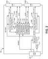
- FIG. 2 is a block diagram of an intelligent power delivery system 200 according to some embodiments, which includes a four-pin input port 202, first and second USB-C output ports 204A, 204B, a dual power delivery (PD) controller 206, first and second buck/boost converters 208A, 208B (e.g., low-side (LS), field effect transistors (FET) power converter), first and second switches 210A, 210B (e.g., high-side (HS) field-effect transistors (FET)), battery input protection circuit 212, and light-emitting diode 214.
- LS low-side
- FET field effect transistors
- dual PD controller 206 further includes first and second PD controllers 216, microcontroller 218, overvoltage (OV) protection circuit 220, V CONN switches 222, and V in /Temp analog-to-digital converter (ADC) 224.
- first and second buck/boost converters 208A, 208B includes an internal low-side (LS) field-effect transistor (FET), with an externally located high-side (HS) field-effect transistor (FET) switch 210A, 210B.
- the internal LS FET and external HS FET provide good thermal performance as compared with integrated converters.
- the LS FETs and HS FETs may be implemented into a single internal buck/boost converter.
- first and second USB-C output ports 204A, 204B are shown, but in other embodiments the intelligent power delivery system 200 may include additional output ports.
- Source power from a battery or generator is provided to the intelligent power delivery system 200 at four-pin input port 202.
- source power may be 12V.
- Source power is distributed through battery input protection circuit 212 to first and second buck/boost converters 208A, 208B and dual PD controller 206.
- dual PD controller 206 communicates with eligible loads or sinks connected to first and second USB-C output ports 204A, 204B via the CC/V CONN and D+/D- channels.
- the dual PD controller 206 utilizes a power delivery protocol to offer and then contract power delivered to loads/sinks connected to the first and second USB-C output ports 204A, 204B.
- dual PD controller 206 Having contracted with one or more loads to deliver contracted power (CP), dual PD controller 206 provides control instructions to first and second buck/boost converters 208A, 208B (as well as HS FETs 210A, 210B) to provide the desired output voltage and current to the respective USB-C output ports 204A, 204B.
- dual PD controller 206 may further include one or more PD controllers 216 (e.g., separate PD controller for each channel or output port), a microcontroller 218, OV protection circuit 220, V CONN switches 222, and Vin/Temp ADCs 224.
- the PD controllers 216 are utilized to generate the control signals provided to the first and second buck/boost converters 208A, 208B to provide the contracted power (labeled here, PD_OUT_1, PD_OUT_2) to the respective USB-C output ports 204A, 204B.
- microcontroller 218 executes stored instructions (e.g., stored to a computer readable medium) to implement one or more functions related to power delivery (e.g., flexible programming of a power delivery (PD) menu utilized to contract power with loads/sinks, load shedding, power sharing algorithms, etc.).
- the Vin/Temp ADCs convert analog temperature and/or monitored voltages (e.g., source voltage provided to four-pin input port 202) to a digital signal that can be utilized by the microcontroller 218.
- microcontroller 218 may utilize the monitored input voltage and/or temperature to adjust the available shared capacity (ASC) available for provision to the one or more USB-C output ports 204A, 204B.
- ASC available shared capacity
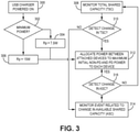
- Figure 3 is a flowchart illustrating steps performed by the power delivery system according to some embodiments.
- Figure 3 illustrates the events that trigger the power delivery system to allocate or re-allocate power between attached devices (shown at step 312).
- the allocation or re-allocation of power at step 312 acts to maximize the initial non-PD (power delivery) power offered to connected chargers/devices and to further maximize the PD power offered to connected chargers/devices.
- the allocation of power between attached devices occurs in response to one or more events occurring, including but not limited to the attachment/detachment of a charger/device from the power delivery system, a change in total shared capacity (TSC) of the power delivery system, and/or a change in the available shared capacity (ASC) of the power delivery system.
- TSC total shared capacity
- ASC available shared capacity
- monitoring of the TSC and ASC may happen continuously in the background, wherein a detected change in either TSC or ASC results in an allocation of power between attached devices at step 312.
- a charger/device being attached/detached to the power delivery system results in an allocation of power between attached devices (or remaining attached devices). In either event, the process used to allocate power remains the same, as described in more detail with respect to Figure 4 .
- the attachment or powering On of a charger attached to one of the output ports at step 300 will initiate the process of allocating power between the attached devices.
- the power delivery system allocates power between attached devices and in particular acts to maximum the initial non-PD power offered to the attached USB charger or device.
- a determination is made at steps 302, 304 and 306 regarding the minimum power to be offered by the power delivery system.
- the minimum power is encoded in the value of resistors (labeled Rp in some embodiments) associated with the output port.
- the minimum power determined at steps 302, 304, and 306 determines how power is allocated at step 312. In other embodiments, the allocation of power at step 312 is performed independent of the value of the minimum power determined at step 302. Typically, the minimum power offered by the power delivery system is set to either 7.5W or 15W. In some embodiments, it is desirable to provide a minimum of 15W to a connected charger or device, even if the minimum assigned by the Rp value is 7.5W, as described with respect to Figure 4 below.
- changes in the TSC and/or ASC of the power delivery system result in an allocation of power between the attached devices at step 312.
- the power delivery system monitors the total shared capacity (TSC), which refers to the total power available to be distributed by the power delivery system.
- TSC total shared capacity
- the TSC may vary in response to one or more factors, including changes to the vehicle battery input voltage, vehicle battery input current, and/or ambient temperature.
- the intelligent power delivery system monitors one or more external parameters, such as ambient temperature, battery voltage, and/or battery current and utilizes the monitored external parameters to detect changes in TSC.
- a decrease in steady state battery voltage corresponds with a decrease in TSC (and vice versa, an increase in steady state battery voltage may indicate an increase in TSC).
- An increase in ambient temperature corresponds to a decrease in TSC (and vice versa, a decrease in ambient temperature corresponds to an increase in TSC).
- a decrease in TSC capacity means less power available to be shared among the connected chargers/devices.
- an increase in TSC capacity in response to an increase in steady state battery voltage/current, decrease in ambient temperature means more power is available to connected chargers/devices. Therefore, at step 310 a determination is made whether a change (increase or decrease) in TSC has been detected.
- this includes comparing the monitored TSC from step 308 to a previously monitored TSC. If a change in TSC is detected at step 310, then power is allocated between attached chargers/devices at step 312. If no change in TSC is detected at step 310, then at step 314 events are monitored related to changes in available shared capacity.
- ASC is measured with respect to a particular output port
- TSC is measured with respect to the entire power delivery system.
- the ASC calculated for a particular port may change (increase or decrease) in response to events happening on other ports.
- events that may result in a change to ASC include a detected capability mis-match between the power delivery system and a connected charger/device, a state of charge associated with a connected charger/device, a change in power consumption associated with a connected charger/device, an over-current condition, a device power give back (e.g., connected charger/device provides power back to the power delivery system), a change in TSC, and/or unique actions based on the connected device and/or power delivery system.
- power is allocated between attached chargers/devices at step 312.
- power is allocated between attached devices.
- the allocation of power between attached devices includes maximizing non-PD power provided to the devices. That is, in response to attachment/detachment of a device, change in TSC, and/or a change in ASC, the initial power offered to connected devices is maximized at step 312.
- PD methods are subsequently utilized to allocate power intelligently between the plurality of connected devices.
- maximizing the initial power offered to a connected device may provide a number of benefits. For example, the USB-C protocol provides power on a first come, first serve basis and only requires that a minimum threshold of power (e.g., 7.5W) be reserved for each unused port (i.e., minimal reserve power).
- a connected device may only be able to draw a minimum amount of power from the power delivery system - one that may provide inadequate charging power.
- the initial power offered may be the final power offered, therefore it is beneficial to maximize the initial power offered at step 312.
- maximizing the initial power offered to a connected device may include decreasing the contracted power provided to one or more other devices.
- maximizing the initial power offered may include modifying the power provided to other devices, this step does not require the connected devices to utilize PD (power delivery) protocols.
- the intelligent power delivery system acts to maximize the initial power provided regardless of whether the connected device is capable of PD communication (e.g., USB-C protocols).
- the initial minimum power contract offered to the attached device at step 312 is provided within an initial time period (e.g., three seconds) of an event (attachment/detachment, TSC change, ASC change) resulting in step 312 being implemented.
- step 312 further includes intelligently allocating power between the respective output ports using a power delivery protocol. This may include further increasing the initial power offered to a device depending on the available shared capacity (ASC) and power requested by the connected load/sink. In some embodiments, the allocation of power between the respective ports is also provided within the initial time period (e.g., three seconds).
- ASC available shared capacity
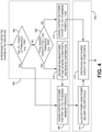
- FIG 4 is a flowchart illustrating in more detail steps utilized to allocate power between attached devices to maximum initial non-PD power and PD power (step 312 shown in Figure 3 ) according to some embodiments.
- step 312 is implemented in response to a attachment/detachment of a device, a change in TSC and/or a change in ASC.
- a first stage illustrated by dashed box 400
- the initial non-PD power is maximized.
- PD protocols are utilized to - to the extent possible - further increase the power provided to a given output port.
- the available shared capacity of other output ports is modified in the second stage in response to the power offered to the given output port.
- the order in which output ports are analyzed may be determined based on the event that resulted in execution of step 312. For example, if a new device is connected to a first output port, then the steps shown in Figure 4 are utilized to maximize the initial non-PD power offered to the newly attached device (and subsequently the PD power offered to the device). Likewise, a change in ASC associated with a given output port may result in the steps shown in Figure 4 being utilized to maximize the initial non-PD power offered to the device following a change in ASC of that particular output port. In other embodiments, a change in TSC may result in application of the steps shown in Figure 4 to each of the output ports having a connected device.
- the order in which output ports are analyzed may be predetermined (e.g., first output port, followed by the second output port, etc.) or may be based on some attribute of the output port (i.e., highest to lowest based on power consumption, etc.).
- the available shared capacity associated with a given output port is compared to a threshold (e.g., first threshold).
- the first threshold represents a minimum power that is considered satisfactory for provision to the connected device (e.g., 15W). If the ASC Pn is greater than the first threshold - indicating that the desired minimum power is available for provision to the given output port - then at step 406 the power delivery system contracts to deliver the desired minimum threshold power to the given output port (e.g., CP Pn) - representing the power contracted for delivery to the given output port.
- the desired minimum threshold is equal to the first threshold (e.g., 15W). In this way, the power delivery system is able to provide an initial power contract to the device connected to the given output port that is greater than a potentially lower minimum power (e.g., 7.5W) reserved for the output port.
- the available shared capacity associated with the given output port is not greater than the first threshold, then this is indicative of a situation in which contracted power assigned to other ports has reduced the available shared capacity available to the given output port such that the desired minimum power is not available.
- the second threshold is greater than the first threshold, and in particular may be approximately twice that of the first threshold threshold. For example, in some embodiments if the first threshold (desired initial power) is equal to 15W, then the third threshold may be set equal to 30W.
- step 408 If at step 408 it is determined that the total shared capacity is not greater than the second threshold (e.g., less than 30W), there is insufficient power available to offer the device connected to the given output port more than the minimum reserve power. As a result, at step 412 the power delivery system offers the device connected to the given output port the minimum reserve power for that port (e.g., 7.5W) and at step 416 the available shared capacity for the other output ports are updated to reflect the contract power offered to the given output port (CP_Pn).
- the second threshold e.g., less than 30W
- the second threshold e.g., greater than 30W
- the second threshold e.g. 15W
- the contract power offered to the one of the other output ports must be decreased. Because the total shared capacity is greater than the third threshold (e.g., 30W), the contracted power offered to devices connected to one of the other output ports (e.g., CP_Pn+1) can be decreased but still maintained above the minimum reserved power.
- the available shared capacity (ASC_Pn) associated with the given output port (7.5W) is less than the second threshold.
- the available shared capacity (ASC_Pn) associated with the given port can be increased to 15W as well.
- the contract power provided to one of the other output ports is decreased (in some embodiments, by an amount equal to the minimum reserve power, or by an amount equal to half the second threshold or desired initial contract offer).
- the contracted power for the device connected to the given output port (CP_Pn) is assigned to the second threshold (e.g., 15W).
- the steps illustrated within dashed box 400 act to maximize the initial non-PD power offered to a device connected to one of the output ports. In most situations, the steps illustrated in dashed box 400 ensures that the initial non-PD power offered to a connected device is satisfactory (e.g., 15W).
- Steps illustrated in dashed box 402 illustrate steps utilized to allocate power using PD protocols.
- step 414 following maximizing of the initial non-PD power associated with a given output port, power may be allocated between the ports intelligently using power delivery protocols.
- power allocation utilizing PD protocols requires the device connected to the output port to be PD compatible. If the device is not PD compatible, then the initial power offered in the first stage (box 400) is maintained. If the device is PD compatible, then the initial power offered in the first stage (box 400) may be increased using PD protocols. In response to the initial non-PD power offered to the given output port and subsequently to the PD power offered to the given output port (if different), the available shared capacity associated with other ports may have changed.
- the ASC of other output ports are updated based on the power provided to the given output port.
- Figure 5 is a flowchart illustrating steps performed by the vehicular charging system to provide intelligent power sharing according to some embodiments.
- a power delivery (PD) protocol is utilized by the power delivery system to communicate with the one or more devices/chargers connected to the output ports and to selectively modify the power provided to the one or more devices/chargers.
- PD protocols are utilized as part of the second stage (illustrated by box 402 in Figure 4 ) to intelligently allocate power to a given output port.
- the steps illustrated in Figure 5 describe one method of providing power delivery according to the present invention.
- available shared capacity (ASC_P) of a given port is determined.
- ASC_P of a given port is a function of the total shared capacity (TSC) and the contracted power (CP) currently being delivered to each of the other ports.
- TSC total shared capacity
- CP contracted power
- a change in the TSC due to a change in the source voltage and/or temperature will result in a change in the ASC_P associated with a particular output port.
- a device determined to be fully charged may result in a decrease in the contracted power delivered to that port.
- the ASP P associated with the other ports will increase in response to a decrease in CP associated with other ports.
- source capabilities are sent to the attached device.
- the menu or message sent to the attached device includes an offer to provide the highest power delivery power (PDP) available.
- the message may further request a response from the device providing one or more fields of information, including an error detecting response (e.g., CRCcheck), power delivery specification menu (e.g., PD2.0 or PD3.0), PDO selection, and/or operating current and max operating current of the device.
- error detecting response e.g., CRCcheck
- power delivery specification menu e.g., PD2.0 or PD3.0
- PDO selection e.g., PDO selection, and/or operating current and max operating current of the device.
- a power delivery device e.g., PDP capable device. For example, if no response is received within a given time limit, a determination is made that the connected device is not PD-capable. If the attached device is not PD capable, then at step 510 the contracted power is assigned a nominal value (e.g., 15W) that is less
- the connected device in response to the query from the power delivery system, provides a requested power (referred to sometimes as a SINK_CAP).
- a requested power referred to sometimes as a SINK_CAP
- the requested power may specify a particular voltage along a continuous range of voltages (e.g., 3.3V to 21V) or the requested power may specify a particular voltage from a plurality of discrete voltage values. In either case, the power delivery system receives a requested power from the connected device.
- the available shared capacity (ASC_P) determined at step 504 is compared to the requested power received from the connected device. If the ASC_P is greater than the requested power, then at step 516 the power delivery system offers the connected device the requested power. At step 520, the power delivery system waits for the contracted power, and then modifies the contracted power (CP) offered to the device. If the ASC_P is less than the requested power, then at step 518 the power delivery system offers the connected device the ASC_P - which is less than the requested power but the maximum available power. Once again, at step 520 the power delivery system waits for contracted power and then at step 522 modifies the CP offered to the device.
- ASC_P available shared capacity
- the steps authorized in Figure 5 may be performed continually during operation of the power delivery system, or may be implemented asynchronously in response to a change in the total shared capacity (TSC) and/or change in charging status of the connected devices.
- TSC total shared capacity
- PD protocols allow for the power offered to a device during the second stage (box 402 as shown in Figure 4 ) to be further increased beyond the initial power offered during the first stage.
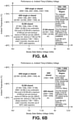
- FIGS. 6A and 6B are charts illustrating the change in total share capacity (TSC) of the power delivery system in response to changes in the steady state battery voltage provided at the input of the power delivery system and to changes in ambient temperature.
- the y-axis illustrates changes in temperature, ranging from -40°C to +80°C.
- the x-axis illustrates the change in steady state battery voltage, ranging from 16V (near the y-axis) to 6V.
- TSC total shared capacity
- TSC total shared capacity
- the total shared capacity is equal to 52.5W, which may be shared between available ports in a number of configurations. Depending on the maximum power per port and the minimum reserve power per port, a variety of combinations are possible. As the temperature increases to between +50°C and +70°C, the total shared capacity decreases to 45W. An additional increase in temperature to between +70°C and +80°C results in the total shared capacity further decreasing to 30W. Likewise, a decrease in steady state battery voltage (in the positive x-direction) corresponds with a decrease in total shared capacity.
- the setpoints for modifying the total shared capacity may be modified based on the application.
- the embodiment shown in Figure 6A illustrates an example in which voltage thresholds for changing the total shared capacity (TSC) are set at 11.5V and 9V.
- temperature thresholds are set at +50°C and +70°C (depending on the steady state battery voltage).
- different thresholds are utilized as well as different total shared capacity (TSC).
- TSC total shared capacity
- ASC_P available shared capacity
- FIGS 7A and 7B are diagrams illustrating intelligent power sharing between first and second ports according to some embodiments.
- additional ports may be associated with the power delivery system.
- TSC total shared capacity
- PDP maximum power delivery power
- CP contracted power
- ASC available shared capacity
- ASC_P 1 TSC ⁇ CP_P 2
- ASC_P 2 TSC ⁇ CP_P 1
- the available shared capacity at any port is equal to or less than the max power delivery power (PDP) available at a given port. For example, if the maximum power delivery power at a given port is 45W, then the available shared capacity must be less than or equal to 45W, even if the total shared capacity is greater.
- PDP power delivery power
- a device is attached to the first port (PI) and is assigned a minimum power of 7.5W.
- a port may be assigned a minimum power reserve (see step 404), wherein the first step is determining a contract power to offer the newly connected device includes assigning a minimum power reserved for the port.
- the available shared capacity ASC_P1 and ASC_P2 remains unchanged despite the contract power of 7.5W assigned to port P1.
- the contract power offered to the first port (PI) is increased from 7.5W to 15W.
- the available shared capacity ASC_P1 for the first port is 45W even though Equation 3 would indicate an available shared capacity ASC_P1 of 52.5W, because ASC_P1 ⁇ PDP (e.g., 45W).
- the first port is assigned contracted power equal to the second threshold (e.g., 15W). In some embodiments, this step is performed within the initial time period (e.g., three seconds) of the device being connected.
- the available shared capacity (ASC_P1) of the first port remains 45W while the available shared capacity (ASC_P2) of the second port is decreased to 37.5W.
- power delivery protocol is utilized to offer the device connected to port 1 additional power.
- this step is also performed within the initial time period (e.g., three seconds) of the device being connected. For example, this action would correspond with step 420 described with respect to Figure 4 .
- the device connected to port 1 requests 45W of power. Given that the available shared capacity (ASC_P1) associated with the first port is equal to 45W, the power delivery system agrees to a contracted power (CP_P1) of 45W. Because no device is connected to the second port, the available shared capacity (ASC_P1) of the first port remains 45W.
- the available shared capacity (ASC_P2) of the second port is decreased to 7.5W (e.g., 52.5W (TSC) - 45W (CP_P1)).
- a second device is attached to the second port (P2).
- the minimum power reserved for the second power is assigned to the second port.
- the available shared capacity (ASC_P2) associated with the second port is equal to 7.5W and the contracted power is likewise equal to 7.5W.
- the contracted power (CP_P1) and available shared capacity (ASC_P1) associated with the first port remain unchanged.
- the steps shown in Figure 4 are utilized to maximize the initial power offered to the second port.
- the available shared capacity (ASC_P2) associated with the second port is less than the second threshold (e.g., 15W) (determined at steps 408 and 410), and because the total shared capacity (52.5W) is greater than a third threshold (e.g., 30W)
- the contracted power (CP_P1) associated with the first port is decreased - in this example from 45W to 37.5W.
- the available shared capacity (ASC_P2) associated with the second port is increased to 15W.
- the contracted power (CP_P2) associated with the second port remains at 7.5W.
- the increased available shared capacity (ASC_P2) associated with the second port is offered to the second port.
- the contract power (CP_P2) associated with the second port is increased from 7.5W to 15W (corresponding with step 422 shown in Figure 4 ), and as a result the available shared capacity (ASC_P1) associated with the first port is decreased from 45W to 37.5W (associated with step 424 shown in Figure 4 ).
- the power delivery system may utilize power delivery protocols to reduce the contract power (CP_P1) provided to the connected device and makes the saved power available to the second device.
- CP_P1 contract power
- a reduction in total shared capacity due to an external event may similarly result in intelligent balancing of power shared among the various ports.
- the device connected to the first port (PI) is disconnected.
- the contracted power (CP_P1) associated with the first port decreases to zero and the available shared capacity (ASC_P2) associated with the second port increases to 45W as a result.
- the power delivery system negotiates with the device connected to the second port to increase the contract power. In some embodiments, this is performed within a first time period following the disconnect of the first device.
- the available shared capacity (ASC_P2) associated with the second port is equal to 45W.
- the power delivery system contracts with the second device to increase the contract power (CP_P2) provided to the connected device.
- the contract power (CP_P2) is equal to 30W.
- the available shared capacity (ASC_P1) associated with the first port is decreased to 22.5W.
- a device is connected again to the first port and is offered the minimum reserve power of 7.5W. This corresponds to step 404 shown in Figure 4 .
- the contract power offered to the first port (PI) is increased from 7.5W to 15W.
- the available shared capacity (ASC_P1) associated with the first port is determined to be greater than the second threshold, resulting in the contracted power (CP_P1) provided to the first device being increased from 7.5W to 15W (step 422 in Figure 4 ).
- the available shared capacity (ASC_P2) associated with the second port is decreased from 45W to 37.5W, but the contract power (CP_P2) remains unchanged at 30W.
- the increase in power provided to the first port is performed within the first time period (e.g. three seconds) following connection of the device to the first port.
- power delivery protocol is utilized to offer the device connected to port 1 additional power.
- this step is also performed within the initial time period (e.g., three seconds) of the device being connected.
- this action would correspond with step 420 described with respect to Figure 4 .
- the device connected to port 1 requests maximum power (e.g., 45W).
- the available shared capacity (ASC_P1) associated with the first port is equal to only 22.5W
- the power delivery system agrees to provide contracted power (CP_P1) at the available 22.5W (rather than the requested 45W).
- the available shared capacity (ASC_P2) of the second port is decreased from 37.5W to 30W.
- the available shared capacity (ASC_P1, ASC_P2) for both ports is 37.5W.
- the available shared capacity reflects the greater magnitude minimum reserve power of 15W (ASC_P1 ⁇ PDP (37.5W), hence the ASC_P1 of 37.5W.
- a device is attached to the first port (PI) and is with provided with the minimum reserved power (15W).
- the available shared capacity (ASC_P2) remains unchanged because th
- a device is connected to port P1.
- the minimum reserve power of 15W is offered to the device and becomes the contracted power (CP_P1).
- the minimum power reserve is offered at step 404.
- the contracted power (CP_P1) is increased from 15W to 37.5W.
- a first threshold e.g. 15W
- the contracted power (CP_P1) is assigned the second threshold (e.g., 15W) as shown at step 422 of Figure 4 .
- a device is connected to the second port (P2) and is offered the minimum reserved power (15W).
- the contract power (CP_P1) and available shared capacity (ASC_P1) associated with the first port remains unchanged.
- the contracted power (CP_P1) is set to 15W.
- the device attached to the first port (PI) is detached.
- the contracted power (CP_P1) is set to zero and the available shared capacity (ASC_P2) associated with the second port is increased to 37.5W.
- the device connected to the first port is detached.
- additional intelligent power sharing may be provided. For example, in some embodiments, in response to the device connected to the first port reaching a fully charged state, power may be allocated from the first port to the second port.
- the power delivery system utilizes power delivery protocols to offer additional power to the device connected to the second port (P2). In some embodiments, this is provided within the first time period following detachment of the device from the first port (PI). In some embodiments, this would be performed at step 420 in the embodiment shown in Figure 4 .
- the device connected to the second port (P2) requests 30W. Because the requested power (30W) is less than the available shared capacity (ASC_P2, 37.5W) associated with the second port, the power delivery system contracts to delivery 30W to the device connected to the second port. The available shared capacity (ASC_P1) associated with the first port is decreased to 22.5W.
- a device is connected to the first port (PI) and is provided with the minimum reserve power (15W).
- the minimum reserve power is greater than the first threshold (15W)
- the contracted power (15W) provided at step 404 is deemed sufficient as an initial power offering and no analysis is provided under steps 408-412.
- the power delivery system utilizes power delivery protocols to offer additional power to the device connected to the first port (PI).
- the device connected to the first port may request 37.5W (as requested at time t3 ).
- the available shared capacity (ASC_P1) associated with the first port is 22.5W
- the request of 37.5W is denied and contracted power for 22.5W is provided instead.
- the available shared capacity (ASC_P2) associated with the second port is decreased to 30W.
- a method of intelligently allocating power to one or more devices connected to a power delivery system includes detecting an event related to an allocation of power between the one or more connected devices. The method further includes maximizing an initial non-power delivery (non-PD) power provided to at least one of the connected devices based on an available shared capacity (ASC) associated with at least one connected device and also includes allocating power to the at least one connected device using PD protocols.
- non-PD non-power delivery
- ASC available shared capacity
- the method of the preceding paragraph can optionally include, additionally and/or alternatively any, one or more of the following features, configurations and/or additional components.
- the step of detecting an event related to an allocation of power between the one or more connected devices may include detecting a device being attached/detached from the power delivery system.
- the step of detecting an event related to an allocation of power between one or more connected devices may include detecting a change in total shared capacity (TSC) of the power delivery system.
- TSC total shared capacity
- the step of detecting a change in total shared capacity (TSC) of the power delivery system may include monitoring one or more of ambient temperature, steady state voltage provided to the power delivery system, and steady state current provided to the power delivery system.
- TSC total shared capacity
- the step of detecting an event related to an allocation of power between one or more connected devices may include detecting a change in available shared capacity (ASC) associated with one or more connected devices.
- ASC available shared capacity
- the step of detecting a change in ASC associated with one or more connected devices may include detecting a capability mis-match between the power delivery system and the one or more connected devices, a state of charge associated with the one or more of the connected devices, a change in power consumption associated with the one or more of the connected devices, an over-current condition, a power give back associated with the one or more of the connected devices, and a change in total shared capacity (TSC).
- TSC total shared capacity
- maximizing an initial non-power delivery (non-PD) power provided to at least one of the connected devices based on an available shared capacity (ASC) associated with the at least one connected device may include comparing an available shared capacity (ASC) associated with the at least one connected device to a first threshold, wherein if the ASC is greater than or equal to the first threshold then the power delivery system provides a desired minimum power to the at least one connected device, wherein the desired minimum power is greater than a minimum reserved power.
- ASC available shared capacity
- the desired minimum power may be equal to or greater than 15W and wherein the minimum reserved power may be less than 15 W.
- a total shared capacity (TSC) of the power delivery system may be compared to a second threshold, wherein if the TSC is greater than or equal to the second threshold then contracted power is decreased with respect to one or more other connected devices and the power delivery system provides the desired minimum threshold power to the at least one connected device.
- TSC total shared capacity
- the second threshold may be greater than the first threshold.
- the power delivery system may provide a minimum reserve power to the at least one connected device, wherein the minimum reserve power is less than the desired minimum threshold power.
- allocating power to the at least one connected device using PD protocols may be performed subsequent to the step of maximizing an initial non-power delivery (non-PD) power provided to at least one of the connected devices, wherein allocating power to the at least one connected device using PD protocols allows contracted power to be provided to the at least one connected device greater than the desired minimum threshold power.
- non-PD non-power delivery
- a power delivery system includes an input port configured to receive power from a power supply and at least a first output port, wherein the first output port is configured to supply power to a connected device.
- the power delivery system further includes a power delivery controller, wherein the power delivery controller maximizes an initial non-power delivery (non-PD) power provided to a device connected to the first output port during a first stage and utilizes power delivery (PD) protocols to increase power provided to the device connected to the first output port during the second stage.
- non-PD initial non-power delivery
- PD power delivery
- the power delivery system of the preceding paragraph can optionally include, additionally and/or alternatively any, one or more of the following features, configurations, and/or additional components.
- the power delivery controller may initiate the first stage in response to at least one of detected attachment/detachment of devices from the first and second output ports, detected changes in total shared capacity (TSC) of power available to distribute to the first output port, and detected changes in available shared capacity (ASC) associated with the first output port.
- TSC total shared capacity
- ASC available shared capacity
- the power delivery controller may calculate the TSC based on one or more of monitored ambient temperature, steady state voltage provided to the input port, and steady state current provided to the input port.
- the power delivery controller may compare an available shared capacity (ASC) associated with a first output port to a first threshold, wherein if the ASC associated with the first output port is greater than or equal to the first threshold then the power delivery controller offers a desired minimum power to the device connected to the first output port.
- ASC available shared capacity
- the power delivery controller may compare a total shared capacity (TSC) of the power delivery system to a second threshold, wherein if the TSC is greater than or equal to the second threshold then the power delivery controller decreases power provided to a device connected to a second output port and offers the desired minimum power to the device connected to the first output port.
- TSC total shared capacity
- the power delivery controller may offer the device connected to the first output port a minimum reserve power, wherein the minimum reserve power is less than the desired minimum power.
- power delivery (PD) protocols utilized during the second stage allow the power delivery controller to increase the contracted power provided to the device connected to the first output port, wherein the increased power may be greater than a desired minimum threshold power provided during the first stage.
- the power delivery system may be a vehicular power delivery system connected to receive input power from a vehicle battery.
Landscapes
- Engineering & Computer Science (AREA)
- Power Engineering (AREA)
- Transportation (AREA)
- Mechanical Engineering (AREA)
- Theoretical Computer Science (AREA)
- Physics & Mathematics (AREA)
- General Engineering & Computer Science (AREA)
- General Physics & Mathematics (AREA)
- Computing Systems (AREA)
- Quality & Reliability (AREA)
- Charge And Discharge Circuits For Batteries Or The Like (AREA)
Abstract
Description
- This application claims the benefit of
U.S. Provisional Patent Application No. 63/072,999, filed September 1, 2020 - Power delivery systems capable of providing charging power to electrical devices are ubiquitous in all physical spaces occupied by people, including automobiles. A power delivery system receives input power from a source and acts to distribute the received power to one or more ports (e.g., USB-type ports). In a typical environment, the power delivery system is connected to the power grid, which is capable of providing a stable supply of power. The power delivery system operates to share the power provided at the input to a plurality of connected loads. For example, the USB-IF provides a framework of general power sharing requirements, but these requirements fail to address some of the challenges presented in, for example, automotive applications that must content with variations of input voltages and temperatures, input power restrictions, and various fault conditions. Additionally, the USB-IF standards do not specify a method for two devices to share power in such a way that optimizes charging for each device. It would therefore be beneficial to develop a framework for handling power delivery/management in an automotive environment.
- According to one aspect, a method of intelligently allocating power to one or more devices connected to a power delivery system includes detecting an event related to an allocation of power between the one or more connected devices. The method further includes maximizing an initial non-power delivery (non-PD) power provided to at least one of the connected devices based on an available shared capacity (ASC) associated with at least one connected device and also includes allocating power to the at least one connected device using PD protocols.
- According to another aspect, a power delivery system includes an input port configured to receive power from a power supply and at least a first output port, wherein the first output port is configured to supply power to a connected device. The power delivery system further includes a power delivery controller, wherein the power delivery controller maximizes an initial non-power delivery (non-PD) power provided to a device connected to the first output port during a first stage and utilizes power delivery (PD) protocols to increase power provided to the device connected to the first output port during the second stage.
-
-
Figure 1 is a block diagram of a vehicular charging system according to some embodiments. -
Figure 2 is a block diagram of an intelligent power delivery system according to some embodiments. -
Figure 3 is a flowchart illustrating steps performed by the power delivery system according to some embodiments. -
Figure 4 is a flowchart illustrating steps performed by the power delivery system to maximize initial non-PD power and PD power supplied to connected devices according to some embodiments. -
Figure 5 is a flowchart illustrating steps performed by the power delivery system to provide PD power to connected devices according to some embodiments. -
Figure 6A and 6B are charts illustrating total shared capacity (TSC) available in response to various input voltages and ambient temperature according to some embodiments. -
Figures 7A and7B are diagrams illustrating intelligent power sharing between first and second ports according to some embodiments. - According to some aspects, an intelligent power delivery system is utilized to intelligently manage power distributed to one or more loads. The power delivery system receives input from a source (e.g., car battery) and acts to intelligently distribute power to one or more output ports. For the purposes of this description, the following terms are utilized to describe the operation of the power delivery system.
- Total Shared Capacity (TSC) - total power available to be distributed by the power delivery system. As described in more detail below, the TSC may vary based on factors external to the power delivery system, including the voltage of the source connected to the input port of the power delivery system, ambient temperature, and/or temperature of components associated with the power delivery system.
- Minimum Reserve Power - fixed value designating a minimum power reserve for each port. That is, while allocating power to one or more ports, power equal to the minimum reserve power is held back to ensure the minimum reserve power is available for distribution to the output port in the event a device is connected.
- Maximum Power Per Port (PDP) - the PDP describes the maximum output power that may be provided to a particular output port. In general, the maximum PDP is based on the TSC as well as the minimum reserve power to ensure that power delivered to a particular port does not render the power delivery system unable to provide at least the minimum reserve power to the remaining output ports.
- Contracted Power (CP) - describes the contracted power delivered by the power delivery system to a particular output port. The contracted power cannot exceed the maximum PDP.
- Available Shared Capacity (ASC) - shared capacity available for allocation to a particular port. The ASC varies based on changes to the TSC and the CP assigned to other ports. For example, the ASC associated with a particular output port may be expressed as the TSC less the contracted power assigned to the other ports. In addition, the ASC cannot exceed the maximum PDP.
- Power Delivery (PD) - Power delivery protocols are utilized to allow communication between the power delivery system and connected devices to negotiate the allocation of power
- According to some aspects, the power delivery system acts to intelligently allocate power to the one or more connected devices. In particular, according to some aspects the power delivery system maximizes an initial non-PD power provided to a connected device during a first stage and then utilizes PD protocols to increase the power offered to the connected device during a second stage. Typically, a minimum reserve power is offered to a connected device, and power delivery protocols are subsequently utilized to allocate unused power to the newly connected device. However, this may result in a newly connected device receiving only the minimum reserve power, which in some cases may not provide adequate device charging/performance. According to some aspects, steps are taken in response to the connection/detachment of a new device to ensure the initial power offered to the newly connected device is greater than a threshold value (e.g., greater than the minimum reserve power). According to another aspect, the power delivery system monitors one or more external parameters that may reduce the total shared capacity (TSC) that can be allocated to the one or more connected devices. For example, in automotive applications the power source (e.g., car battery) utilized to supply power to the power delivery system may vary in the power made available. The power delivery system acts to monitor these external parameters and adjust the TSC associated with the power delivery system based on the external parameters. Changes in the TSC result in changes to the available shared capacity (ASC), and therefore to the contract power (CP) that can be provided to the connected devices. In some cases, a decrease in the TSC results in a corresponding decrease or load shedding of CP offered to the one or more connected devices. According to another aspect, the power delivery system monitors the device charging parameters associated with connected devices. For example, a determination that a device has reached a fully charged state and/or requires less charging power indicates that CP associated with the connected device can be reduced and made available to one or more other connected devices.
-
Figure 1 is a block diagram of a vehicular charging system according to some embodiments. The vehicle charging system includes apower delivery system 100, having aninput port 102 and one ormore output ports Input port 102 is configured to receive power from vehicle battery/power supply 106.Output ports Power delivery system 100 further includes apower delivery controller 110 that intelligently shares power between theoutput ports Figure 1 shows only first andsecond output ports power delivery system 100. A single output port may be utilized, although a number of the power sharing requirements would not longer be applicable. - In some embodiments, the output power provided by the vehicle battery/
power supply 106 may vary in response to one or more conditions. For example, in some embodiments the output power provided by the vehicle battery/power supply 106 varies with ambient temperature and/or battery voltage. Changes in the power provided by the vehicle battery/power supply 106 changes the total power - referred to as the total shared capacity (TSC) - that can be provided tooutput ports power delivery controller 110 responds to changes in the total shared capacity (TSC) by decreasing contracted power (CP) provided to one or both of theoutput ports - In some embodiments,
power delivery system 100 intelligently manages changes in power sharing betweenrespective output ports output ports device power delivery controller 110 implements functions to maximize the initial power contract provided to a connected load. In some embodiments, this may include modifying power contracts associated with one or more of the other output ports in order to maximize the initial power contract provided to the output port. In some embodiments, thepower delivery system 100 may also provide intelligent power sharing tooutput ports output port 104B may result in a reduction of contract power (CP_P2) offered tooutput port 104B and a corresponding increase in contract power (CP_P1) offered tooutput port 104A. As described in more detail below,power delivery controller 110 may provide additional intelligent load shedding and/or power sharing. -
Figure 2 is a block diagram of an intelligentpower delivery system 200 according to some embodiments, which includes a four-pin input port 202, first and second USB-C output ports controller 206, first and second buck/boost converters second switches input protection circuit 212, and light-emittingdiode 214. In some embodiments,dual PD controller 206 further includes first andsecond PD controllers 216,microcontroller 218, overvoltage (OV)protection circuit 220, VCONN switches 222, and Vin/Temp analog-to-digital converter (ADC) 224. In the embodiment shown inFigure 2 , first and second buck/boost converters switch Figure 2 , only first and second USB-C output ports power delivery system 200 may include additional output ports. - Source power from a battery or generator is provided to the intelligent
power delivery system 200 at four-pin input port 202. For example, in an automotive application, source power may be 12V. Source power is distributed through batteryinput protection circuit 212 to first and second buck/boost converters dual PD controller 206. In some embodiments,dual PD controller 206 communicates with eligible loads or sinks connected to first and second USB-C output ports dual PD controller 206 utilizes a power delivery protocol to offer and then contract power delivered to loads/sinks connected to the first and second USB-C output ports dual PD controller 206 provides control instructions to first and second buck/boost converters HS FETs C output ports - In some embodiments,
dual PD controller 206 may further include one or more PD controllers 216 (e.g., separate PD controller for each channel or output port), amicrocontroller 218,OV protection circuit 220, VCONN switches 222, and Vin/Temp ADCs 224. In some embodiments, thePD controllers 216 are utilized to generate the control signals provided to the first and second buck/boost converters C output ports microcontroller 218 executes stored instructions (e.g., stored to a computer readable medium) to implement one or more functions related to power delivery (e.g., flexible programming of a power delivery (PD) menu utilized to contract power with loads/sinks, load shedding, power sharing algorithms, etc.). In some embodiments, the Vin/Temp ADCs convert analog temperature and/or monitored voltages (e.g., source voltage provided to four-pin input port 202) to a digital signal that can be utilized by themicrocontroller 218. For example, as described in more detail below,microcontroller 218 may utilize the monitored input voltage and/or temperature to adjust the available shared capacity (ASC) available for provision to the one or more USB-C output ports -
Figure 3 is a flowchart illustrating steps performed by the power delivery system according to some embodiments. In general,Figure 3 illustrates the events that trigger the power delivery system to allocate or re-allocate power between attached devices (shown at step 312). In general, the allocation or re-allocation of power atstep 312 acts to maximize the initial non-PD (power delivery) power offered to connected chargers/devices and to further maximize the PD power offered to connected chargers/devices. - In general, the allocation of power between attached devices occurs in response to one or more events occurring, including but not limited to the attachment/detachment of a charger/device from the power delivery system, a change in total shared capacity (TSC) of the power delivery system, and/or a change in the available shared capacity (ASC) of the power delivery system. As shown in
Figure 3 , monitoring of the TSC and ASC may happen continuously in the background, wherein a detected change in either TSC or ASC results in an allocation of power between attached devices atstep 312. In addition, a charger/device being attached/detached to the power delivery system results in an allocation of power between attached devices (or remaining attached devices). In either event, the process used to allocate power remains the same, as described in more detail with respect toFigure 4 . - As shown in
Figure 3 , the attachment or powering On of a charger attached to one of the output ports atstep 300 will initiate the process of allocating power between the attached devices. In In some embodiments, having detecting that a USB charger has been attached or powered on atstep 300, then atstep 312 the power delivery system allocates power between attached devices and in particular acts to maximum the initial non-PD power offered to the attached USB charger or device. In some embodiments, in response to a USB charger being connected or powered on atstep 300, a determination is made atsteps steps step 312. In other embodiments, the allocation of power atstep 312 is performed independent of the value of the minimum power determined atstep 302. Typically, the minimum power offered by the power delivery system is set to either 7.5W or 15W. In some embodiments, it is desirable to provide a minimum of 15W to a connected charger or device, even if the minimum assigned by the Rp value is 7.5W, as described with respect toFigure 4 below. - In addition to the attachment and/or powering On of a charging device, changes in the TSC and/or ASC of the power delivery system result in an allocation of power between the attached devices at
step 312. For example, in some embodiments atstep 308 the power delivery system monitors the total shared capacity (TSC), which refers to the total power available to be distributed by the power delivery system. In automotive applications, the TSC may vary in response to one or more factors, including changes to the vehicle battery input voltage, vehicle battery input current, and/or ambient temperature. In some embodiments, the intelligent power delivery system monitors one or more external parameters, such as ambient temperature, battery voltage, and/or battery current and utilizes the monitored external parameters to detect changes in TSC. For example, a decrease in steady state battery voltage (shown inFigures 6A, 6B , for example) corresponds with a decrease in TSC (and vice versa, an increase in steady state battery voltage may indicate an increase in TSC). An increase in ambient temperature corresponds to a decrease in TSC (and vice versa, a decrease in ambient temperature corresponds to an increase in TSC). As the name implies, a decrease in TSC capacity means less power available to be shared among the connected chargers/devices. Likewise, an increase in TSC capacity (in response to an increase in steady state battery voltage/current, decrease in ambient temperature) means more power is available to connected chargers/devices. Therefore, at step 310 a determination is made whether a change (increase or decrease) in TSC has been detected. In some embodiments, this includes comparing the monitored TSC fromstep 308 to a previously monitored TSC. If a change in TSC is detected atstep 310, then power is allocated between attached chargers/devices atstep 312. If no change in TSC is detected atstep 310, then atstep 314 events are monitored related to changes in available shared capacity. - At
step 314, events are monitored with respect to changes in ASC. In some embodiments, ASC is measured with respect to a particular output port, whereas TSC is measured with respect to the entire power delivery system. However, the ASC calculated for a particular port may change (increase or decrease) in response to events happening on other ports. For example, in some embodiments events that may result in a change to ASC (on a particular port) include a detected capability mis-match between the power delivery system and a connected charger/device, a state of charge associated with a connected charger/device, a change in power consumption associated with a connected charger/device, an over-current condition, a device power give back (e.g., connected charger/device provides power back to the power delivery system), a change in TSC, and/or unique actions based on the connected device and/or power delivery system. In response to a detected change in ASC atstep 316 power is allocated between attached chargers/devices atstep 312. - At
step 312, power is allocated between attached devices. In some embodiments, the allocation of power between attached devices includes maximizing non-PD power provided to the devices. That is, in response to attachment/detachment of a device, change in TSC, and/or a change in ASC, the initial power offered to connected devices is maximized atstep 312. In some embodiments, PD methods are subsequently utilized to allocate power intelligently between the plurality of connected devices. However, maximizing the initial power offered to a connected device may provide a number of benefits. For example, the USB-C protocol provides power on a first come, first serve basis and only requires that a minimum threshold of power (e.g., 7.5W) be reserved for each unused port (i.e., minimal reserve power). As result, it is possible that a connected device may only be able to draw a minimum amount of power from the power delivery system - one that may provide inadequate charging power. For non-PD devices (i.e., those not capable of negotiating allocation of power with the power delivery system intelligently) the initial power offered may be the final power offered, therefore it is beneficial to maximize the initial power offered atstep 312. As described in more detail with respect toFigure 4 , maximizing the initial power offered to a connected device may include decreasing the contracted power provided to one or more other devices. Although maximizing the initial power offered may include modifying the power provided to other devices, this step does not require the connected devices to utilize PD (power delivery) protocols. That is, the intelligent power delivery system acts to maximize the initial power provided regardless of whether the connected device is capable of PD communication (e.g., USB-C protocols). In some embodiments, the initial minimum power contract offered to the attached device atstep 312 is provided within an initial time period (e.g., three seconds) of an event (attachment/detachment, TSC change, ASC change) resulting instep 312 being implemented. - In some embodiments, following provision of the initial minimum power contract provided to the newly connected device, step 312 further includes intelligently allocating power between the respective output ports using a power delivery protocol. This may include further increasing the initial power offered to a device depending on the available shared capacity (ASC) and power requested by the connected load/sink. In some embodiments, the allocation of power between the respective ports is also provided within the initial time period (e.g., three seconds).
-
Figure 4 is a flowchart illustrating in more detail steps utilized to allocate power between attached devices to maximum initial non-PD power and PD power (step 312 shown inFigure 3 ) according to some embodiments. As described above,step 312 is implemented in response to a attachment/detachment of a device, a change in TSC and/or a change in ASC. During a first stage (illustrated by dashed box 400) the initial non-PD power is maximized. During a second stage (illustrated by dashed box 402), PD protocols are utilized to - to the extent possible - further increase the power provided to a given output port. In addition, the available shared capacity of other output ports is modified in the second stage in response to the power offered to the given output port. - The order in which output ports are analyzed may be determined based on the event that resulted in execution of
step 312. For example, if a new device is connected to a first output port, then the steps shown inFigure 4 are utilized to maximize the initial non-PD power offered to the newly attached device (and subsequently the PD power offered to the device). Likewise, a change in ASC associated with a given output port may result in the steps shown inFigure 4 being utilized to maximize the initial non-PD power offered to the device following a change in ASC of that particular output port. In other embodiments, a change in TSC may result in application of the steps shown inFigure 4 to each of the output ports having a connected device. The order in which output ports are analyzed may be predetermined (e.g., first output port, followed by the second output port, etc.) or may be based on some attribute of the output port (i.e., highest to lowest based on power consumption, etc.). - At
step 404, the available shared capacity associated with a given output port (ASC_Pn) is compared to a threshold (e.g., first threshold). In some embodiments, the first threshold represents a minimum power that is considered satisfactory for provision to the connected device (e.g., 15W). If the ASC Pn is greater than the first threshold - indicating that the desired minimum power is available for provision to the given output port - then atstep 406 the power delivery system contracts to deliver the desired minimum threshold power to the given output port (e.g., CP Pn) - representing the power contracted for delivery to the given output port. In some embodiments, the desired minimum threshold is equal to the first threshold (e.g., 15W). In this way, the power delivery system is able to provide an initial power contract to the device connected to the given output port that is greater than a potentially lower minimum power (e.g., 7.5W) reserved for the output port. - If at
step 404 the available shared capacity associated with the given output port (ASC_Pn) is not greater than the first threshold, then this is indicative of a situation in which contracted power assigned to other ports has reduced the available shared capacity available to the given output port such that the desired minimum power is not available. In response, at step 408 a determination is made whether the total shared capacity (TSC) is greater than a second threshold. In some embodiments, the second threshold is greater than the first threshold, and in particular may be approximately twice that of the first threshold threshold. For example, in some embodiments if the first threshold (desired initial power) is equal to 15W, then the third threshold may be set equal to 30W. - If at
step 408 it is determined that the total shared capacity is not greater than the second threshold (e.g., less than 30W), there is insufficient power available to offer the device connected to the given output port more than the minimum reserve power. As a result, atstep 412 the power delivery system offers the device connected to the given output port the minimum reserve power for that port (e.g., 7.5W) and atstep 416 the available shared capacity for the other output ports are updated to reflect the contract power offered to the given output port (CP_Pn). If atstep 408 it is determined that the total shared capacity is greater than the second threshold (e.g., greater than 30W), there is sufficient power available to offer the device connected to the given output port more than the minimum reserve power, despite the available shared capacity of the given output port (ASC_Pn) being less than the second threshold (e.g., 15W). However, in order to provide the device connected to the given output port with contracted power greater than the minimum reserved power, the contract power offered to the one of the other output ports must be decreased. Because the total shared capacity is greater than the third threshold (e.g., 30W), the contracted power offered to devices connected to one of the other output ports (e.g., CP_Pn+1) can be decreased but still maintained above the minimum reserved power. For example, if the total shared capacity is equal to 30W, and the contract power offered to a second output port (CP_P2) is equal to 22.5W, then the available shared capacity (ASC_Pn) associated with the given output port (7.5W) is less than the second threshold. However, by decreasing the contract power offered to the second port (CP_P2) from 22.5W to 15W, the available shared capacity (ASC_Pn) associated with the given port can be increased to 15W as well. In this way, atstep 410 the contract power provided to one of the other output ports is decreased (in some embodiments, by an amount equal to the minimum reserve power, or by an amount equal to half the second threshold or desired initial contract offer). Upon receiving confirmation that the contracted power associated with one of the other output ports has been decreased atstep 410, then atstep 406 the contracted power for the device connected to the given output port (CP_Pn) is assigned to the second threshold (e.g., 15W). - In this way, the steps illustrated within dashed
box 400 act to maximize the initial non-PD power offered to a device connected to one of the output ports. In most situations, the steps illustrated in dashedbox 400 ensures that the initial non-PD power offered to a connected device is satisfactory (e.g., 15W). - Steps illustrated in dashed
box 402 illustrate steps utilized to allocate power using PD protocols. Atstep 414, following maximizing of the initial non-PD power associated with a given output port, power may be allocated between the ports intelligently using power delivery protocols. In some embodiments, power allocation utilizing PD protocols requires the device connected to the output port to be PD compatible. If the device is not PD compatible, then the initial power offered in the first stage (box 400) is maintained. If the device is PD compatible, then the initial power offered in the first stage (box 400) may be increased using PD protocols. In response to the initial non-PD power offered to the given output port and subsequently to the PD power offered to the given output port (if different), the available shared capacity associated with other ports may have changed. Atstep 416 the ASC of other output ports are updated based on the power provided to the given output port. -
Figure 5 is a flowchart illustrating steps performed by the vehicular charging system to provide intelligent power sharing according to some embodiments. In some embodiments, a power delivery (PD) protocol is utilized by the power delivery system to communicate with the one or more devices/chargers connected to the output ports and to selectively modify the power provided to the one or more devices/chargers. In some embodiments, PD protocols are utilized as part of the second stage (illustrated bybox 402 inFigure 4 ) to intelligently allocate power to a given output port. The steps illustrated inFigure 5 describe one method of providing power delivery according to the present invention. - At
step 504, available shared capacity (ASC_P) of a given port is determined. As described above, ASC_P of a given port is a function of the total shared capacity (TSC) and the contracted power (CP) currently being delivered to each of the other ports. Thus, a change in the TSC due to a change in the source voltage and/or temperature will result in a change in the ASC_P associated with a particular output port. Likewise, a device determined to be fully charged may result in a decrease in the contracted power delivered to that port. Although the total shared capacity has not changed in this instance, the ASP P associated with the other ports will increase in response to a decrease in CP associated with other ports. - At
step 506, source capabilities are sent to the attached device. In some embodiments, the menu or message sent to the attached device includes an offer to provide the highest power delivery power (PDP) available. The message may further request a response from the device providing one or more fields of information, including an error detecting response (e.g., CRCcheck), power delivery specification menu (e.g., PD2.0 or PD3.0), PDO selection, and/or operating current and max operating current of the device. - At
step 508, based on the response received from the device, a determination is made whether the attached device is a power delivery device (e.g., PDP capable device). For example, if no response is received within a given time limit, a determination is made that the connected device is not PD-capable. If the attached device is not PD capable, then atstep 510 the contracted power is assigned a nominal value (e.g., 15W) that is less than or equal to the available shared capacity (ASC_P) of the given port. In some embodiments, the nominal value is equal to the first threshold described with respect toFigure 4 (e.g., 15W). If the device is a PDP device, then the power delivery system is capable of communicating and modifying contracted power. - At
step 512, in response to the query from the power delivery system, the connected device provides a requested power (referred to sometimes as a SINK_CAP). Depending on the power delivery specification utilized by the connected device, the requested power may specify a particular voltage along a continuous range of voltages (e.g., 3.3V to 21V) or the requested power may specify a particular voltage from a plurality of discrete voltage values. In either case, the power delivery system receives a requested power from the connected device. - At
step 514, the available shared capacity (ASC_P) determined atstep 504 is compared to the requested power received from the connected device. If the ASC_P is greater than the requested power, then atstep 516 the power delivery system offers the connected device the requested power. Atstep 520, the power delivery system waits for the contracted power, and then modifies the contracted power (CP) offered to the device. If the ASC_P is less than the requested power, then atstep 518 the power delivery system offers the connected device the ASC_P - which is less than the requested power but the maximum available power. Once again, atstep 520 the power delivery system waits for contracted power and then atstep 522 modifies the CP offered to the device. The steps authorized inFigure 5 may be performed continually during operation of the power delivery system, or may be implemented asynchronously in response to a change in the total shared capacity (TSC) and/or change in charging status of the connected devices. In this way, PD protocols allow for the power offered to a device during the second stage (box 402 as shown inFigure 4 ) to be further increased beyond the initial power offered during the first stage. -
Figure 6A and 6B are charts illustrating the change in total share capacity (TSC) of the power delivery system in response to changes in the steady state battery voltage provided at the input of the power delivery system and to changes in ambient temperature. The y-axis illustrates changes in temperature, ranging from -40°C to +80°C. The x-axis illustrates the change in steady state battery voltage, ranging from 16V (near the y-axis) to 6V. In general, as the steady state battery voltage decreases, the total shared capacity (TSC) decreases. Likewise, as the temperature increases, the total shared capacity (TSC) decreases. For example, given a steady state input voltage of 16V to 11.5V and an ambient temperature of -40°C to +50°C, the total shared capacity is equal to 52.5W, which may be shared between available ports in a number of configurations. Depending on the maximum power per port and the minimum reserve power per port, a variety of combinations are possible. As the temperature increases to between +50°C and +70°C, the total shared capacity decreases to 45W. An additional increase in temperature to between +70°C and +80°C results in the total shared capacity further decreasing to 30W. Likewise, a decrease in steady state battery voltage (in the positive x-direction) corresponds with a decrease in total shared capacity. - The setpoints for modifying the total shared capacity (TSC) may be modified based on the application. For example, the embodiment shown in
Figure 6A illustrates an example in which voltage thresholds for changing the total shared capacity (TSC) are set at 11.5V and 9V. Likewise, temperature thresholds are set at +50°C and +70°C (depending on the steady state battery voltage). In the embodiment shown inFigure 6B , different thresholds are utilized as well as different total shared capacity (TSC). - As discussed above, changes in the total shared capacity (TSC) cause changes to the available shared capacity (ASC_P) calculated for each of the plurality of ports. A decrease in total shared capacity (TSC) results in a corresponding decrease in available shared capacity (ASC_P) for each of the plurality of ports, and may therefore require re-negotiating contracted power (CP) with one or more of the plurality of ports to ensure that the sum of the contracted power (CP) is less than the total shared capacity (TSC).
-
Figures 7A and7B are diagrams illustrating intelligent power sharing between first and second ports according to some embodiments. In other embodiments, additional ports may be associated with the power delivery system. However, for the sake of simplicity a simple two-port power delivery system is described. The embodiment shown inFigure 7A assumes intelligent power sharing based on a total shared capacity (TSC) of 52.5W, a maximum power delivery power (PDP) of 45W per port, and a required minimum power of 7.5W. With respect to each port - Port 1 (PI), and Port 2 (P2) - the contracted power (CP) is shown without parentheses and the available shared capacity (ASC) is shown in parentheses. - As described above, the available shared capacity at each port is defined as follows:


- In addition, it is assumed for this exercise that the available shared capacity at any port is equal to or less than the max power delivery power (PDP) available at a given port. For example, if the maximum power delivery power at a given port is 45W, then the available shared capacity must be less than or equal to 45W, even if the total shared capacity is greater.
- In the embodiment shown in
Figure 7A , at time t1 neither is receiving power and therefore neither port is assigned a contracted power (CP) value. As a result, the available shared capacity at each port is equal to 45W. As described above, even though the total shared capacity in the example is 52.5W, the available shared capacity (ASC) at any port must be less than or equal to the maximum power delivery power (PDP) at the given port. - At time t2, a device is attached to the first port (PI) and is assigned a minimum power of 7.5W. As discussed above, in some embodiments a port may be assigned a minimum power reserve (see step 404), wherein the first step is determining a contract power to offer the newly connected device includes assigning a minimum power reserved for the port. In this instance, the available shared capacity ASC_P1 and ASC_P2 remains unchanged despite the contract power of 7.5W assigned to port P1.
- At time t3, the contract power offered to the first port (PI) is increased from 7.5W to 15W. As described with respect to
Figure 4 , in the instant case the available shared capacity ASC_P1 for the first port is 45W even though Equation 3 would indicate an available shared capacity ASC_P1 of 52.5W, because ASC_P1 < PDP (e.g., 45W). As described inFigure 4 atsteps - At time t4, power delivery protocol is utilized to offer the device connected to
port 1 additional power. In some embodiments, this step is also performed within the initial time period (e.g., three seconds) of the device being connected. For example, this action would correspond with step 420 described with respect toFigure 4 . In this embodiment, the device connected toport 1requests 45W of power. Given that the available shared capacity (ASC_P1) associated with the first port is equal to 45W, the power delivery system agrees to a contracted power (CP_P1) of 45W. Because no device is connected to the second port, the available shared capacity (ASC_P1) of the first port remains 45W. However, because the contracted power (CP_P1) offered to the first port is equal to 45W, the available shared capacity (ASC_P2) of the second port is decreased to 7.5W (e.g., 52.5W (TSC) - 45W (CP_P1)). - At time t5, a second device is attached to the second port (P2). In response, the minimum power reserved for the second power is assigned to the second port. At this point, the available shared capacity (ASC_P2) associated with the second port is equal to 7.5W and the contracted power is likewise equal to 7.5W. The contracted power (CP_P1) and available shared capacity (ASC_P1) associated with the first port remain unchanged.
- At time t6, the steps shown in
Figure 4 are utilized to maximize the initial power offered to the second port. In this example, because the available shared capacity (ASC_P2) associated with the second port is less than the second threshold (e.g., 15W) (determined atsteps 408 and 410), and because the total shared capacity (52.5W) is greater than a third threshold (e.g., 30W), atstep 416 the contracted power (CP_P1) associated with the first port is decreased - in this example from 45W to 37.5W. As a result of this reduction in contracted power provided to the first port, the available shared capacity (ASC_P2) associated with the second port is increased to 15W. For the time being, the contracted power (CP_P2) associated with the second port remains at 7.5W. - At time t7, the increased available shared capacity (ASC_P2) associated with the second port is offered to the second port. The contract power (CP_P2) associated with the second port is increased from 7.5W to 15W (corresponding with step 422 shown in
Figure 4 ), and as a result the available shared capacity (ASC_P1) associated with the first port is decreased from 45W to 37.5W (associated with step 424 shown inFigure 4 ). - In the embodiment shown in
Figure 7A , at time t8 the first device is disconnected from the first port. However, assuming that the first device is not disconnected from the first port (P1), then at subsequent time intervals power delivery protocols could be utilized to intelligently balance the distribution of power to the ports. For example, in response to the first connected device reaching a fully charged state, the power delivery system may utilize power delivery protocols to reduce the contract power (CP_P1) provided to the connected device and makes the saved power available to the second device. In other embodiments, a reduction in total shared capacity due to an external event (decrease in source voltage, increase temperature, tec.) may similarly result in intelligent balancing of power shared among the various ports. - At time t8, the device connected to the first port (PI) is disconnected. As a result, the contracted power (CP_P1) associated with the first port decreases to zero and the available shared capacity (ASC_P2) associated with the second port increases to 45W as a result.
- At time t9, the power delivery system negotiates with the device connected to the second port to increase the contract power. In some embodiments, this is performed within a first time period following the disconnect of the first device. In this example, the available shared capacity (ASC_P2) associated with the second port is equal to 45W. The power delivery system contracts with the second device to increase the contract power (CP_P2) provided to the connected device. In this example, the contract power (CP_P2) is equal to 30W. As a result, the available shared capacity (ASC_P1) associated with the first port is decreased to 22.5W.
- At time t10, a device is connected again to the first port and is offered the minimum reserve power of 7.5W. This corresponds to step 404 shown in
Figure 4 . The available shared capacity (ASC_P1, ASC_P2) associated with the first port and the second port, respectively, remains unchanged. - At time t11, the contract power offered to the first port (PI) is increased from 7.5W to 15W. As described with respect to
Figure 4 , atsteps Figure 4 ). In response, the available shared capacity (ASC_P2) associated with the second port is decreased from 45W to 37.5W, but the contract power (CP_P2) remains unchanged at 30W. As discussed above, in some embodiments the increase in power provided to the first port is performed within the first time period (e.g. three seconds) following connection of the device to the first port. - At time t12, power delivery protocol is utilized to offer the device connected to
port 1 additional power. In some embodiments, this step is also performed within the initial time period (e.g., three seconds) of the device being connected. For example, this action would correspond with step 420 described with respect toFigure 4 . In this embodiment, the device connected toport 1 requests maximum power (e.g., 45W). Given that the available shared capacity (ASC_P1) associated with the first port is equal to only 22.5W, the power delivery system agrees to provide contracted power (CP_P1) at the available 22.5W (rather than the requested 45W). In addition, the available shared capacity (ASC_P2) of the second port is decreased from 37.5W to 30W. - With respect to
Figure 7B , another scenario is provide in which the total shared capacity is equal to 52.5W, the maximum power delivery power (PDP) is set to 37.5W and a minimum power reserve is set to 15W. - At time t1, no devices are connected to either of the ports. As a result, neither port has a contracted power (CP) value, and the available shared capacity (ASC_P1, ASC_P2) for both ports is 37.5W. In contrast with the example provided in
Figure 7A , the available shared capacity reflects the greater magnitude minimum reserve power of 15W (ASC_P1 ≤ PDP (37.5W), hence the ASC_P1 of 37.5W. - At time t2, a device is attached to the first port (PI) and is with provided with the minimum reserved power (15W). The available shared capacity (ASC_P2) remains unchanged because th
- At time t2, a device is connected to port P1. In this example, the minimum reserve power of 15W is offered to the device and becomes the contracted power (CP_P1). With respect to
Figure 4 , the minimum power reserve is offered atstep 404. The contracted power (CP_P1) is set to 15W, and the available shared capacity (ASC_P2) remains at 37.5W (ASC_P2 (37.5W) = TSC (52.5W) -CP_P1 (15W)). - At time t3, within the initial time period following connection of the first device the contracted power (CP_P1) is increased from 15W to 37.5W. In this example, because the minimum reserve power is greater than a first threshold (e.g., 15W), there is no need to perform the analysis described at
Figure 4 with respect to steps 408-412. Rather, the contracted power (CP_P1) is assigned the second threshold (e.g., 15W) as shown at step 422 ofFigure 4 . The available shared capacity (ASC_P2) associated with the second port is changed to 15W (ASC_P2 (15W) = TSC (52.5W) - CP_P1 (37.5W)). - At time t4, a device is connected to the second port (P2) and is offered the minimum reserved power (15W). The contract power (CP_P1) and available shared capacity (ASC_P1) associated with the first port remains unchanged. Once again, because the minimum reserve power (15W) is greater than the first threshold (at step 406), the contracted power (CP_P1) is set to 15W.
- At time t5, the device attached to the first port (PI) is detached. As a result, the contracted power (CP_P1) is set to zero and the available shared capacity (ASC_P2) associated with the second port is increased to 37.5W. In the example provided in
Figure 7B , at time t6 the device connected to the first port is detached. However, if the device were not disconnected then in the time subsequent to time t5 additional intelligent power sharing may be provided. For example, in some embodiments, in response to the device connected to the first port reaching a fully charged state, power may be allocated from the first port to the second port. - At time t6, the power delivery system utilizes power delivery protocols to offer additional power to the device connected to the second port (P2). In some embodiments, this is provided within the first time period following detachment of the device from the first port (PI). In some embodiments, this would be performed at step 420 in the embodiment shown in
Figure 4 . In the example shown inFigure 4 , the device connected to the second port (P2) requests 30W. Because the requested power (30W) is less than the available shared capacity (ASC_P2, 37.5W) associated with the second port, the power delivery system contracts todelivery 30W to the device connected to the second port. The available shared capacity (ASC_P1) associated with the first port is decreased to 22.5W. - At time t7, a device is connected to the first port (PI) and is provided with the minimum reserve power (15W). As discussed above, because the minimum reserve power is greater than the first threshold (15W), the contracted power (15W) provided at
step 404 is deemed sufficient as an initial power offering and no analysis is provided under steps 408-412. - At time t8, the power delivery system utilizes power delivery protocols to offer additional power to the device connected to the first port (PI). In this example, the device connected to the first port may request 37.5W (as requested at time t3). However, because the available shared capacity (ASC_P1) associated with the first port is 22.5W, the request of 37.5W is denied and contracted power for 22.5W is provided instead. In addition, the available shared capacity (ASC_P2) associated with the second port is decreased to 30W.
- While the invention has been described with reference to an exemplary embodiment(s), it will be understood by those skilled in the art that various changes may be made and equivalents may be substituted for elements thereof without departing from the scope of the invention. In addition, many modifications may be made to adapt a particular situation or material to the teachings of the invention without departing from the essential scope thereof. Therefore, it is intended that the invention not be limited to the particular embodiment(s) disclosed, but that the invention will include all embodiments falling within the scope of the appended claims.
- The following are non-exclusive descriptions of possible embodiments of the present invention.
- According to one aspect, a method of intelligently allocating power to one or more devices connected to a power delivery system includes detecting an event related to an allocation of power between the one or more connected devices. The method further includes maximizing an initial non-power delivery (non-PD) power provided to at least one of the connected devices based on an available shared capacity (ASC) associated with at least one connected device and also includes allocating power to the at least one connected device using PD protocols.
- The method of the preceding paragraph can optionally include, additionally and/or alternatively any, one or more of the following features, configurations and/or additional components.
- For example, the step of detecting an event related to an allocation of power between the one or more connected devices may include detecting a device being attached/detached from the power delivery system.
- In some embodiments, the step of detecting an event related to an allocation of power between one or more connected devices may include detecting a change in total shared capacity (TSC) of the power delivery system.
- In some embodiments, the step of detecting a change in total shared capacity (TSC) of the power delivery system may include monitoring one or more of ambient temperature, steady state voltage provided to the power delivery system, and steady state current provided to the power delivery system.
- In some embodiments, the step of detecting an event related to an allocation of power between one or more connected devices may include detecting a change in available shared capacity (ASC) associated with one or more connected devices.
- In some embodiments, the step of detecting a change in ASC associated with one or more connected devices may include detecting a capability mis-match between the power delivery system and the one or more connected devices, a state of charge associated with the one or more of the connected devices, a change in power consumption associated with the one or more of the connected devices, an over-current condition, a power give back associated with the one or more of the connected devices, and a change in total shared capacity (TSC).
- In some embodiments, maximizing an initial non-power delivery (non-PD) power provided to at least one of the connected devices based on an available shared capacity (ASC) associated with the at least one connected device may include comparing an available shared capacity (ASC) associated with the at least one connected device to a first threshold, wherein if the ASC is greater than or equal to the first threshold then the power delivery system provides a desired minimum power to the at least one connected device, wherein the desired minimum power is greater than a minimum reserved power.
- In some embodiments, the desired minimum power may be equal to or greater than 15W and wherein the minimum reserved power may be less than 15 W.
- In some embodiments, if the ASC is less than the first threshold then a total shared capacity (TSC) of the power delivery system may be compared to a second threshold, wherein if the TSC is greater than or equal to the second threshold then contracted power is decreased with respect to one or more other connected devices and the power delivery system provides the desired minimum threshold power to the at least one connected device.
- In some embodiments, the second threshold may be greater than the first threshold.
- In some embodiments, if the TSC is less than the second threshold then the power delivery system may provide a minimum reserve power to the at least one connected device, wherein the minimum reserve power is less than the desired minimum threshold power.
- In some embodiments, allocating power to the at least one connected device using PD protocols may be performed subsequent to the step of maximizing an initial non-power delivery (non-PD) power provided to at least one of the connected devices, wherein allocating power to the at least one connected device using PD protocols allows contracted power to be provided to the at least one connected device greater than the desired minimum threshold power.
- According to another aspect, a power delivery system includes an input port configured to receive power from a power supply and at least a first output port, wherein the first output port is configured to supply power to a connected device. The power delivery system further includes a power delivery controller, wherein the power delivery controller maximizes an initial non-power delivery (non-PD) power provided to a device connected to the first output port during a first stage and utilizes power delivery (PD) protocols to increase power provided to the device connected to the first output port during the second stage.
- The power delivery system of the preceding paragraph can optionally include, additionally and/or alternatively any, one or more of the following features, configurations, and/or additional components.
- In some embodiments, the power delivery controller may initiate the first stage in response to at least one of detected attachment/detachment of devices from the first and second output ports, detected changes in total shared capacity (TSC) of power available to distribute to the first output port, and detected changes in available shared capacity (ASC) associated with the first output port.
- In some embodiments, the power delivery controller may calculate the TSC based on one or more of monitored ambient temperature, steady state voltage provided to the input port, and steady state current provided to the input port.
- In some embodiments, during the first stage the power delivery controller may compare an available shared capacity (ASC) associated with a first output port to a first threshold, wherein if the ASC associated with the first output port is greater than or equal to the first threshold then the power delivery controller offers a desired minimum power to the device connected to the first output port.
- In some embodiments, if the ASC associated with the first output port is less than the first threshold, then the power delivery controller may compare a total shared capacity (TSC) of the power delivery system to a second threshold, wherein if the TSC is greater than or equal to the second threshold then the power delivery controller decreases power provided to a device connected to a second output port and offers the desired minimum power to the device connected to the first output port.
- In some embodiments, if the TSC is less than the second threshold then the power delivery controller may offer the device connected to the first output port a minimum reserve power, wherein the minimum reserve power is less than the desired minimum power.
- In some embodiments, power delivery (PD) protocols utilized during the second stage allow the power delivery controller to increase the contracted power provided to the device connected to the first output port, wherein the increased power may be greater than a desired minimum threshold power provided during the first stage.
- In some embodiments, the power delivery system may be a vehicular power delivery system connected to receive input power from a vehicle battery.
Claims (15)
- A method of intelligently allocating power to one or more devices connected to a power delivery system, the method comprising:detecting an event related to an allocation of power between the one or more connected devices (steps 300, 310, 316);maximizing an initial non-power delivery (non-PD) power provided to at least one of the connected devices based on an available shared capacity (ASC) associated with at least one connected device (steps 312, 400); andallocating power to the at least one connected device using PD protocols (steps 312, 414).
- The method of claim 1, wherein detecting an event related to an allocation of power between the one or more connected devices includes detecting a device being attached/detached from the power delivery system (step 300) and/or detecting a change in total shared capacity (TSC) of the power delivery system (step 310) and/or detecting a change in available shared capacity (ASC) associated with one or more connected devices (step 316).
- The method of claim 2, wherein detecting a change in total shared capacity (TSC) of the power delivery system includes monitoring one or more of ambient temperature, steady state voltage provided to the power delivery system, and steady state current provided to the power delivery system (step 308).
- The method of claim 2, wherein detecting a change in ASC associated with one or more connected devices includes a detected capability mis-match between the power delivery system and the one or more connected devices, a state of charge associated with the one or more of the connected devices, a change in power consumption associated with the one or more of the connected devices, an over-current condition, a power give back associated with the one or more of the connected devices, and a change in total shared capacity (TSC).
- The method of claim 1, 2, 3, or 4, wherein maximizing an initial non-power delivery (non-PD) power provided to at least one of the connected devices based on an available shared capacity (ASC) associated with the at least one connected device includes comparing an available shared capacity (ASC) associated with the at least one connected device to a first threshold (step 404), wherein if the ASC is greater than or equal to the first threshold then the power delivery system provides a desired minimum power to the at least one connected device (step 406), wherein the desired minimum power is greater than a minimum reserved power.
- The method of claim 5, wherein the desired minimum power is equal to or greater than 15W and wherein the minimum reserved power is less than 15 W.
- The method of claim 5 or 6, wherein if the ASC is less than the first threshold then a total shared capacity (TSC) of the power delivery system is compared to a second threshold (step 408), wherein if the TSC is greater than or equal to the second threshold then the power delivery system provides decreases power provided to one or more other connected devices (step 410) and the power delivery system provides the desired minimum threshold power to the at least one connected device (step 406), wherein the second threshold is greater than the first threshold.
- The method of claim 7, wherein if the TSC is less than the second threshold then the power delivery system provides a minimum reserve power to the at least one connected device (step 412), wherein the minimum reserve power is less than the desired minimum threshold power.
- The method of any of the preceding claims, wherein allocating power to the at least one connected device using PD protocols (steps 312, 414) is performed subsequent to the step of maximizing an initial non-power delivery (non-PD) power provided to at least one of the connected devices, wherein allocating power to the at least one connected device using PD protocols allows the power delivery system to provide power to the at least one connected device greater than a desired minimum threshold power.
- A power delivery system (100, 200) comprising:an input port (102, 202) configured to receive power from a power supply (106);at least a first output port (104A, 204A), wherein the first output port (104A, 204A) is configured to supply power to a connected device (108A); anda power delivery controller (110, 206), wherein the power delivery controller maximizes an initial non-power delivery (non-PD) power provided to [[a]] the device (108A) connected to the first output port (104A, 204A) during a first stage and utilizes power delivery (PD) protocols to increase power provided to the device (108A) connected to the first output port (104A, 204A) during a second stage.
- The power delivery system (100, 200) of claim 10, wherein the power delivery controller (110, 206) initiates the first stage in response to at least one of detected attachment/detachment of devices from the first output port (104A, 204A), detected changes in total shared capacity (TSC) of power available to distribute to the first output port (104A, 204A), and detected changes in available shared capacity (ASC) associated with the first output port (104A, 204A).
- The power delivery system (100, 200) of claim 11, wherein the power delivery controller (110, 206) calculates the TSC based on one or more of monitored ambient temperature, steady state voltage provided to the input port (102, 202), and steady state current provided to the input port (102, 202).
- The power delivery system (100, 200) of claim 11 or 12, wherein during the first stage the power delivery controller (110, 206) compares an available shared capacity (ASC) associated with a first output port (104A, 204A) to a first threshold, wherein if the ASC associated with the first output port (104A, 204A) is greater than or equal to the first threshold then the power delivery controller (110, 206) offers a desired minimum power to the device connected to the first output port (104A, 204A).
- The power delivery system (100, 200) of claim 13, wherein if the ASC associated with the first output port (104A, 204A) is less than the first threshold, then the power delivery controller (110, 206) compares a total shared capacity (TSC) of the power delivery system to a second threshold, wherein if the TSC is greater than or equal to the second threshold then the power delivery controller (110, 206) decreases power provided to a device connected to a second output port (104B, 204B) and offers the desired minimum power to the device connected to the first output port (104A, 204A), wherein if the TSC is less than the second threshold then the power delivery controller (110, 206) offers the device connected to the first output port (104A, 204A) a minimum reserve power, wherein the minimum reserve power is less than the desired minimum power.
- The power delivery system (100, 200) of any of claims 10 - 14, wherein power delivery (PD) protocols utilized during the second stage allows the power delivery controller (110, 206) to increase power provided to the device connected to the first output port (104A, 204A), wherein the power is greater than a desired minimum threshold power provided during the first stage.
Applications Claiming Priority (2)
| Application Number | Priority Date | Filing Date | Title |
|---|---|---|---|
| US202063072999P | 2020-09-01 | 2020-09-01 | |
| US17/146,978 US11904718B2 (en) | 2020-09-01 | 2021-01-12 | System and method of intelligently allocating power |
Publications (1)
| Publication Number | Publication Date |
|---|---|
| EP3961851A1 true EP3961851A1 (en) | 2022-03-02 |
Family
ID=77864316
Family Applications (1)
| Application Number | Title | Priority Date | Filing Date |
|---|---|---|---|
| EP21194054.9A Pending EP3961851A1 (en) | 2020-09-01 | 2021-08-31 | System and method of intelligently allocating power |
Country Status (3)
| Country | Link |
|---|---|
| US (2) | US11904718B2 (en) |
| EP (1) | EP3961851A1 (en) |
| CN (2) | CN114116580B (en) |
Families Citing this family (5)
| Publication number | Priority date | Publication date | Assignee | Title |
|---|---|---|---|---|
| US20220171443A1 (en) * | 2020-11-28 | 2022-06-02 | Siliconch System Pvt Ltd | Method for facilitating dynamic power distribution in a multiport power sourcing device |
| US12552221B2 (en) * | 2022-09-27 | 2026-02-17 | Cummins Inc. | Dynamic management of vehicle functions according to power demand |
| KR20260003414A (en) * | 2023-05-18 | 2026-01-06 | 에이디케이 엘엘씨 디비에이 인디 세미컨덕터 | In-vehicle consumer device charging network |
| US12237671B1 (en) * | 2024-07-12 | 2025-02-25 | Osee Technology Ltd. | Internal power supply apparatus for auxiliary device supporting power delivery protocol |
| CN119116765A (en) * | 2024-08-01 | 2024-12-13 | 西安放芯充新能源科技有限公司 | An integrated multi-port hybrid charging pile and control method |
Citations (3)
| Publication number | Priority date | Publication date | Assignee | Title |
|---|---|---|---|---|
| CN108664113A (en) * | 2017-03-28 | 2018-10-16 | 瑞萨电子株式会社 | Power supply equipment, supply of electric power control device and supply of electric power control method |
| US20180356873A1 (en) * | 2017-06-13 | 2018-12-13 | Intel Corporation | Method to enhance device policy management (dpm) power sharing for usb type-c (usb-c) only devices |
| WO2020141511A1 (en) * | 2019-01-01 | 2020-07-09 | Advanced Magnetic Solutions Limited | Controlled power adapter |
Family Cites Families (8)
| Publication number | Priority date | Publication date | Assignee | Title |
|---|---|---|---|---|
| US10114401B2 (en) * | 2013-11-18 | 2018-10-30 | Infineon Technologies Ag | System and method for a serial bus interface |
| EP3043442B1 (en) * | 2015-01-12 | 2024-12-04 | SIMPower Technology Inc. | Hub having complex power converters |
| US10048731B2 (en) * | 2015-06-26 | 2018-08-14 | Intel Corporation | Mitigation of charging induced voltage offset |
| US10224727B2 (en) * | 2015-06-30 | 2019-03-05 | Dong-Sheng Li | Multi-functional hub integrated with AC power supply |
| JP6626384B2 (en) * | 2016-03-23 | 2019-12-25 | ローム株式会社 | Power supply device and power supply method, control circuit, AC adapter, electronic device |
| CN106099997B (en) * | 2016-06-27 | 2019-02-26 | 国电南瑞科技股份有限公司 | Allocation method of interconnected power grid reserve and shared capacity considering safety constraints |
| CN107706972A (en) * | 2017-09-30 | 2018-02-16 | 湖南海翼电子商务股份有限公司 | Power output control method, circuit and charging device for charging device |
| US11106260B2 (en) * | 2018-02-13 | 2021-08-31 | Microsoft Technology Licensing, Llc | Smart charging platform |
-
2021
- 2021-01-12 US US17/146,978 patent/US11904718B2/en active Active
- 2021-08-31 EP EP21194054.9A patent/EP3961851A1/en active Pending
- 2021-09-01 CN CN202111022935.6A patent/CN114116580B/en active Active
- 2021-09-01 CN CN202411963734.XA patent/CN119883999B/en active Active
-
2024
- 2024-01-12 US US18/411,683 patent/US12187150B2/en active Active
Patent Citations (3)
| Publication number | Priority date | Publication date | Assignee | Title |
|---|---|---|---|---|
| CN108664113A (en) * | 2017-03-28 | 2018-10-16 | 瑞萨电子株式会社 | Power supply equipment, supply of electric power control device and supply of electric power control method |
| US20180356873A1 (en) * | 2017-06-13 | 2018-12-13 | Intel Corporation | Method to enhance device policy management (dpm) power sharing for usb type-c (usb-c) only devices |
| WO2020141511A1 (en) * | 2019-01-01 | 2020-07-09 | Advanced Magnetic Solutions Limited | Controlled power adapter |
Also Published As
| Publication number | Publication date |
|---|---|
| CN114116580B (en) | 2025-01-10 |
| US11904718B2 (en) | 2024-02-20 |
| US20240149735A1 (en) | 2024-05-09 |
| US20220063436A1 (en) | 2022-03-03 |
| CN119883999B (en) | 2025-10-28 |
| US12187150B2 (en) | 2025-01-07 |
| CN114116580A (en) | 2022-03-01 |
| CN119883999A (en) | 2025-04-25 |
Similar Documents
| Publication | Publication Date | Title |
|---|---|---|
| EP3961851A1 (en) | System and method of intelligently allocating power | |
| EP2985857B1 (en) | Storage battery management system and storage battery management method | |
| US7414381B2 (en) | Charging circuit for parallel charging in multiple battery systems | |
| CN108462167B (en) | USB power management and load distribution system | |
| US9281718B2 (en) | On-board power supply monitor and power control system | |
| US6314009B1 (en) | Device and method for controlled parallel operation of direct current converters | |
| CN1330070C (en) | Power management wake-up circuit, method and apparatus | |
| US20040230844A1 (en) | Power management system including a variable voltage link | |
| US12015298B2 (en) | Configurable integrated power delivery module with adaptive power sharing | |
| US8054598B1 (en) | Negotiating capacity allocation among distributed current protection devices | |
| US20190044194A1 (en) | Cell balancing system and control method | |
| WO2020084822A1 (en) | Voltage supply system and power source constituting same | |
| KR20160088916A (en) | Dynamic voltage adjust circuits and methods | |
| US20210111578A1 (en) | Usb type-c interface circuit and charging method thereof, usb device | |
| US9906072B2 (en) | Systems and methods for matching an end of discharge for multiple batteries | |
| WO2020141511A1 (en) | Controlled power adapter | |
| EP1612908B1 (en) | Multi-regulator power supply chip with common control bus | |
| US20170308137A1 (en) | System and method for rack over provisioning and intelligent power management | |
| US20250123665A1 (en) | Multi-port power delivery system and power allocation method thereof | |
| US20250239879A1 (en) | Onboard control apparatus | |
| JP7824020B2 (en) | power distribution equipment | |
| CN113895373A (en) | Energy management system and method for high-voltage accessories of electric automobile and intelligent automobile | |
| US20260039123A1 (en) | Adaptable power allocation for multi-port charger systems | |
| US10811887B2 (en) | Charging voltage supply apparatus and supply method | |
| US20250392147A1 (en) | Multi-port usb power control system |
Legal Events
| Date | Code | Title | Description |
|---|---|---|---|
| PUAI | Public reference made under article 153(3) epc to a published international application that has entered the european phase |
Free format text: ORIGINAL CODE: 0009012 |
|
| STAA | Information on the status of an ep patent application or granted ep patent |
Free format text: STATUS: THE APPLICATION HAS BEEN PUBLISHED |
|
| AK | Designated contracting states |
Kind code of ref document: A1 Designated state(s): AL AT BE BG CH CY CZ DE DK EE ES FI FR GB GR HR HU IE IS IT LI LT LU LV MC MK MT NL NO PL PT RO RS SE SI SK SM TR |
|
| STAA | Information on the status of an ep patent application or granted ep patent |
Free format text: STATUS: REQUEST FOR EXAMINATION WAS MADE |
|
| 17P | Request for examination filed |
Effective date: 20220823 |
|
| RBV | Designated contracting states (corrected) |
Designated state(s): AL AT BE BG CH CY CZ DE DK EE ES FI FR GB GR HR HU IE IS IT LI LT LU LV MC MK MT NL NO PL PT RO RS SE SI SK SM TR |
|
| STAA | Information on the status of an ep patent application or granted ep patent |
Free format text: STATUS: EXAMINATION IS IN PROGRESS |
|
| 17Q | First examination report despatched |
Effective date: 20230224 |
|
| RAP1 | Party data changed (applicant data changed or rights of an application transferred) |
Owner name: APTIV TECHNOLOGIES AG |
|
| RAP3 | Party data changed (applicant data changed or rights of an application transferred) |
Owner name: APTIV TECHNOLOGIES AG |
|
| GRAP | Despatch of communication of intention to grant a patent |
Free format text: ORIGINAL CODE: EPIDOSNIGR1 |
|
| STAA | Information on the status of an ep patent application or granted ep patent |
Free format text: STATUS: GRANT OF PATENT IS INTENDED |
|
| GRAJ | Information related to disapproval of communication of intention to grant by the applicant or resumption of examination proceedings by the epo deleted |
Free format text: ORIGINAL CODE: EPIDOSDIGR1 |
|
| STAA | Information on the status of an ep patent application or granted ep patent |
Free format text: STATUS: EXAMINATION IS IN PROGRESS |
|
| RIN1 | Information on inventor provided before grant (corrected) |
Inventor name: YEDA, SHYAMBABU Inventor name: ELGHRAWI, MOHAMAD Inventor name: BERRY, LUKE Inventor name: BURCHETT, ANDREW Inventor name: COOKE, CHRIS |
|
| INTG | Intention to grant announced |
Effective date: 20251014 |
|
| INTC | Intention to grant announced (deleted) |