EP3961809A1 - Antenna for vehicle - Google Patents
Antenna for vehicle Download PDFInfo
- Publication number
- EP3961809A1 EP3961809A1 EP20796197.0A EP20796197A EP3961809A1 EP 3961809 A1 EP3961809 A1 EP 3961809A1 EP 20796197 A EP20796197 A EP 20796197A EP 3961809 A1 EP3961809 A1 EP 3961809A1
- Authority
- EP
- European Patent Office
- Prior art keywords
- vehicle
- power feeding
- feeding point
- roof
- sun roof
- Prior art date
- Legal status (The legal status is an assumption and is not a legal conclusion. Google has not performed a legal analysis and makes no representation as to the accuracy of the status listed.)
- Withdrawn
Links
- 230000001747 exhibiting effect Effects 0.000 claims abstract description 8
- 239000004020 conductor Substances 0.000 claims abstract description 7
- 238000012545 processing Methods 0.000 claims description 4
- 239000011521 glass Substances 0.000 description 11
- 230000000007 visual effect Effects 0.000 description 8
- 238000010586 diagram Methods 0.000 description 6
- 229910052751 metal Inorganic materials 0.000 description 4
- 239000002184 metal Substances 0.000 description 4
- 238000004891 communication Methods 0.000 description 3
- 229910000831 Steel Inorganic materials 0.000 description 2
- 229910052782 aluminium Inorganic materials 0.000 description 2
- XAGFODPZIPBFFR-UHFFFAOYSA-N aluminium Chemical compound [Al] XAGFODPZIPBFFR-UHFFFAOYSA-N 0.000 description 2
- 239000003575 carbonaceous material Substances 0.000 description 2
- 238000003780 insertion Methods 0.000 description 2
- 230000037431 insertion Effects 0.000 description 2
- 239000010959 steel Substances 0.000 description 2
- 238000000034 method Methods 0.000 description 1
- 238000012986 modification Methods 0.000 description 1
- 230000004048 modification Effects 0.000 description 1
- 238000006467 substitution reaction Methods 0.000 description 1
Images


Classifications
-
- H—ELECTRICITY
- H01—ELECTRIC ELEMENTS
- H01Q—ANTENNAS, i.e. RADIO AERIALS
- H01Q13/00—Waveguide horns or mouths; Slot antennas; Leaky-waveguide antennas; Equivalent structures causing radiation along the transmission path of a guided wave
- H01Q13/10—Resonant slot antennas
-
- H—ELECTRICITY
- H01—ELECTRIC ELEMENTS
- H01Q—ANTENNAS, i.e. RADIO AERIALS
- H01Q1/00—Details of, or arrangements associated with, antennas
- H01Q1/12—Supports; Mounting means
- H01Q1/1271—Supports; Mounting means for mounting on windscreens
- H01Q1/1278—Supports; Mounting means for mounting on windscreens in association with heating wires or layers
-
- H—ELECTRICITY
- H01—ELECTRIC ELEMENTS
- H01Q—ANTENNAS, i.e. RADIO AERIALS
- H01Q1/00—Details of, or arrangements associated with, antennas
- H01Q1/27—Adaptation for use in or on movable bodies
- H01Q1/32—Adaptation for use in or on road or rail vehicles
- H01Q1/325—Adaptation for use in or on road or rail vehicles characterised by the location of the antenna on the vehicle
- H01Q1/3275—Adaptation for use in or on road or rail vehicles characterised by the location of the antenna on the vehicle mounted on a horizontal surface of the vehicle, e.g. on roof, hood, trunk
Definitions
- the present invention relates to a vehicle antenna.
- Patent Literature 1 discloses a technique of providing an antenna element to a glass lid of a sun roof, which deals with various types of wireless communication systems and devices relating to AM or FM radio broadcasts, the Global Positioning System (GPS), the Electronic Toll Collection System (ETC), the Vehicle Information and Communication System (VICS (registered trademark)), ground wave digital television broadcasts, inter-vehicle communication, and the like.
- GPS Global Positioning System
- ETC Electronic Toll Collection System
- VICS Vehicle Information and Communication System
- ground wave digital television broadcasts inter-vehicle communication, and the like.
- Patent Literature 1 Japanese unexamined utility model application publication No. H5-9012
- the automobile antenna causes inconvenience because the antenna pattern formed on the glass lid obstructs a visual field of a passenger.
- a vehicle antenna according to the present invention is a vehicle antenna applied to a vehicle including a sun roof.
- the vehicle antenna includes a sun roof forming opening exhibiting a rectangular shape at one location on a roof of the vehicle, the roof being formed of a conductive material, a first power feeding point provided to one long side of the sun roof forming opening, a second power feeding point provided to another long side of the sun roof forming opening, a hot-side conducting wire connected to the first power feeding point, and an earth-side conducting wire connected to the second power feeding point.
- the sun roof formed at the one location of the roof of the vehicle can be provided with an antenna function as a slot antenna without obstructing a visual field of a passenger.
- a vehicle antenna according to the present invention is a vehicle antenna applied to a vehicle including a sun roof.
- the vehicle antenna includes a first sun roof forming opening and a second sun roof forming opening exhibiting a rectangular shape and being formed, on a roof of the vehicle, in parallel to have long sides facing each other, the roof being formed of a conductive material, a first power feeding point provided to a long side of the first sun roof forming opening on a facing side, a second power feeding point provided to a long side of the second sun roof forming opening on a facing side, a hot-side conducting wire connected to the first power feeding point, and an earth-side conducting wire connected to the second power feeding point.
- the sun roofs formed at the two locations of the roof of the vehicle can be provided with an antenna function as a slot antenna without obstructing a visual field of a passenger.
- the hot-side conducting wire may be connected to one end of a core wire of a co-axial cable laid in the vehicle, the earth-side conducting wire may be connected to an outer cover wire of the co-axial cable, another end of the core wire may be connected to a signal processing device provided to the vehicle, and the outer cover wire may be earth-connected to a conductive portion of the vehicle body.
- the simple configuration enables the sun roof to have an antenna function as a slot antenna without obstructing a visual field of a passenger.
- the vehicle antenna capable of providing the sun roof with an antenna function without obstructing a visual field of a passenger.
- FIG. 1 to FIG. 7 With reference to FIG. 1 to FIG. 7 , one embodiment of the present invention is described.
- a sun roof SRI including a glass lid 11 is provided to a roof (roof section) 10 of a vehicle V.
- the glass lid 11 of the sun roof SRI is fixed.
- the glass lid 11 may include a mechanism that slides in a front-rear direction, a right-left direction, or the like.
- the roof 10 is formed of a conductive material such as a steel plate, an aluminum plate, and a carbonaceous material.
- a sun roof forming opening 12 exhibiting a rectangular shape engageable with the glass lid 11 is formed at one location close to the front side of the roof 10.
- a first power feeding point n1 is provided to one long side L1 of the sun roof forming opening 12.
- a second power feeding point n2 is provided to the other long side L2 of the sun roof forming opening 12.
- a hot-side conducting wire 101a is connected to the first power feeding point n1, and an earth-side conducting wire 102a is connected to the second power feeding point n2.
- the hot-side conducting wire 101a is connected to one end of a core wire 101 of a co-axial cable 100 laid in a space formed between the roof 10 and a ceiling plate 15 of the vehicle V.
- the earth-side conducting wire 102a is connected to an outer cover wire 102 of the co-axial cable 100.
- the outer cover wire 102 of the co-axial cable 100 is earth-connected to predetermined conductive portion of a vehicle body B by a fixing metal fitting 250 and a screw 251.
- the hot-side conducting wire 101a and the earth-side conducting wire 102a are attached to a vehicle inner side of the roof 10 (a side facing the ceiling plate 15) through intermediation of terminal metal fittings T1 and T2 each having a bolt insertion hole 160.
- the hot-side conducting wire 101a and the earth-side conducting wire 102a have the same length.
- the other end of the core wire 101 is connected to a signal processing device 300 or the like provided to the vehicle V.
- a vehicle antenna A1 according to this embodiment has antenna characteristics as illustrated in FIG. 6A to FIG. 6C .
- FIG. 6A is a diagram showing orientation of the sun roof SR1 and the like.
- FIG. 6B is a diagram showing vertically polarized directivity
- FIG. 6C is a diagram showing horizontally polarized directivity.
- the sun roof SRI formed at the one location of the roof 10 of the vehicle can be provided with an antenna function as a slot antenna without obstructing a visual field of a passenger.
- FIG. 7 is a schematic configuration view illustrating a schematic configuration of a vehicle antenna A2 according to a second embodiment.
- sun roofs SRI and SR2 including the glass lids 11 are provided at two locations of the roof (roof section) 10 of the vehicle V.
- the glass lids 11a and 11b of the sun roofs SR1 and SR2 are fixed.
- the glass lids 11a and 11b may each include a mechanism that slides in a front-rear direction, a right-left direction, or the like.
- the roof 10 is formed of a conductive material such as a steel plate, an aluminum plate, and a carbonaceous material.
- a first sun roof forming opening 12a exhibiting a rectangular shape engageable with the glass lid 11a is formed close to the front side of the roof 10.
- a second sun roof forming opening 12b exhibiting a rectangular shape engageable with the glass lid 11b is formed close to the rear side of the roof 10.
- the first sun roof forming opening 12a and the second sun roof forming opening 12b are formed in parallel to have long sides L1 and L3 facing each other.
- a first power feeding point n11 is provided to the long side L1 of the first sun roof forming opening 12a on the facing side.
- a second power feeding point n12 is provided to the long side L3 of the first sun roof forming opening 12b on the facing side.
- the hot-side conducting wire 101a is connected to the first power feeding point n11.
- the earth-side conducting wire 102a is connected to the second power feeding point n12.
- the hot-side conducting wire 101a is connected to the one side of the core wire 101 of the co-axial cable 100 laid in the space formed between the roof 10 and the ceiling plate 15 of the vehicle V.
- the earth-side conducting wire 102a is connected to the outer cover wire 102 of the co-axial cable 100.
- the outer cover wire 102 of the co-axial cable 100 is earth-connected to the predetermined conductive portion of the vehicle body B by the fixing metal fitting 250 and the screw 251.
- the hot-side conducting wire 101a and the earth-side conducting wire 102a can be attached to the vehicle inner side of the roof 10 (the side facing the ceiling plate 15) through intermediation of the terminal metal fittings T1 and T2 each having the bolt insertion hole 160.
- the other end of the core wire 101 is connected to the signal processing device 300 or the like provided to the vehicle V.
- the hot-side conducting wire 101a and the earth-side conducting wire 102a have the same length.
- the sun roofs SRI and SR2 formed at the one location of the roof 10 of the vehicle V can be provided with an antenna function as a slot antenna without obstructing a visual field of a passenger.
- the vehicle antenna and the like of the present invention are described above based on the illustrated embodiments. However, the present invention is not limited thereto, and the configurations of the respective elements may be replaced with freely-selected configurations having similar functions.
Landscapes
- Engineering & Computer Science (AREA)
- Remote Sensing (AREA)
- Details Of Aerials (AREA)
- Support Of Aerials (AREA)
- Waveguide Aerials (AREA)
Abstract
Description
- The present invention relates to a vehicle antenna.
- Patent Literature 1 discloses a technique of providing an antenna element to a glass lid of a sun roof, which deals with various types of wireless communication systems and devices relating to AM or FM radio broadcasts, the Global Positioning System (GPS), the Electronic Toll Collection System (ETC), the Vehicle Information and Communication System (VICS (registered trademark)), ground wave digital television broadcasts, inter-vehicle communication, and the like.
- Patent Literature 1:
Japanese unexamined utility model application publication No. H5-9012 - However, the automobile antenna causes inconvenience because the antenna pattern formed on the glass lid obstructs a visual field of a passenger.
- It is an object of the present invention to provide a vehicle antenna capable of providing a sun roof with an antenna function without obstructing a visual field of a passenger.
- A vehicle antenna according to the present invention is a vehicle antenna applied to a vehicle including a sun roof. The vehicle antenna includes a sun roof forming opening exhibiting a rectangular shape at one location on a roof of the vehicle, the roof being formed of a conductive material, a first power feeding point provided to one long side of the sun roof forming opening, a second power feeding point provided to another long side of the sun roof forming opening, a hot-side conducting wire connected to the first power feeding point, and an earth-side conducting wire connected to the second power feeding point.
- With this, the sun roof formed at the one location of the roof of the vehicle can be provided with an antenna function as a slot antenna without obstructing a visual field of a passenger.
- A vehicle antenna according to the present invention is a vehicle antenna applied to a vehicle including a sun roof. The vehicle antenna includes a first sun roof forming opening and a second sun roof forming opening exhibiting a rectangular shape and being formed, on a roof of the vehicle, in parallel to have long sides facing each other, the roof being formed of a conductive material, a first power feeding point provided to a long side of the first sun roof forming opening on a facing side, a second power feeding point provided to a long side of the second sun roof forming opening on a facing side, a hot-side conducting wire connected to the first power feeding point, and an earth-side conducting wire connected to the second power feeding point.
- With this, the sun roofs formed at the two locations of the roof of the vehicle can be provided with an antenna function as a slot antenna without obstructing a visual field of a passenger.
- In the vehicle antenna according to the present invention, the hot-side conducting wire may be connected to one end of a core wire of a co-axial cable laid in the vehicle, the earth-side conducting wire may be connected to an outer cover wire of the co-axial cable, another end of the core wire may be connected to a signal processing device provided to the vehicle, and the outer cover wire may be earth-connected to a conductive portion of the vehicle body.
- With this, the simple configuration enables the sun roof to have an antenna function as a slot antenna without obstructing a visual field of a passenger.
- According to the present invention, there can be provided the vehicle antenna capable of providing the sun roof with an antenna function without obstructing a visual field of a passenger.
-
-
FIG. 1 is a side view illustrating a vehicle on which a vehicle antenna according to a first embodiment is mounted. -
FIG. 2 is a top view illustrating the vehicle on which the vehicle antenna according to the first embodiment is mounted. -
FIG. 3 is a schematic configuration view illustrating a schematic configuration of the vehicle antenna according to the first embodiment. -
FIG. 4 is a schematic explanatory view illustrating a configuration example of the vehicle antenna according to the first embodiment. -
FIG. 5 is a schematic explanatory view illustrating a configuration example of a co-axial cable and a terminal that are applied in the vehicle antenna according to the first embodiment. -
FIG. 6A is a characteristic diagram of the vehicle antenna according to the first embodiment. -
FIG. 6B is a characteristic diagram of the vehicle antenna according to the first embodiment. -
FIG. 6C is a characteristic diagram of the vehicle antenna according to the first embodiment. -
FIG. 7 is a schematic configuration view illustrating a schematic configuration of a vehicle antenna according to a second embodiment. - With reference to the drawings, a vehicle antenna according to this embodiment is described below in detail.
- With reference to
FIG. 1 to FIG. 7 , one embodiment of the present invention is described. - As illustrated in
FIG. 1 to FIG. 3 , a sun roof SRI including aglass lid 11 is provided to a roof (roof section) 10 of a vehicle V. - In this embodiment, the
glass lid 11 of the sun roof SRI is fixed. Alternatively, theglass lid 11 may include a mechanism that slides in a front-rear direction, a right-left direction, or the like. - The
roof 10 is formed of a conductive material such as a steel plate, an aluminum plate, and a carbonaceous material. - A sun roof forming opening 12 exhibiting a rectangular shape engageable with the
glass lid 11 is formed at one location close to the front side of theroof 10. - A first power feeding point n1 is provided to one long side L1 of the sun roof forming opening 12.
- A second power feeding point n2 is provided to the other long side L2 of the sun roof forming opening 12.
- A hot-side conducting
wire 101a is connected to the first power feeding point n1, and an earth-side conductingwire 102a is connected to the second power feeding point n2. - More specifically, as illustrated in
FIG. 3 andFIG. 4 , the hot-side conductingwire 101a is connected to one end of acore wire 101 of aco-axial cable 100 laid in a space formed between theroof 10 and aceiling plate 15 of the vehicle V. - The earth-side conducting
wire 102a is connected to anouter cover wire 102 of theco-axial cable 100. Theouter cover wire 102 of theco-axial cable 100 is earth-connected to predetermined conductive portion of a vehicle body B by a fixingmetal fitting 250 and ascrew 251. - The hot-side conducting
wire 101a and the earth-side conductingwire 102a are attached to a vehicle inner side of the roof 10 (a side facing the ceiling plate 15) through intermediation of terminal metal fittings T1 and T2 each having abolt insertion hole 160. - In order to improve antenna characteristics, it is desired that the hot-side conducting
wire 101a and the earth-side conductingwire 102a have the same length. - Meanwhile, the other end of the
core wire 101 is connected to asignal processing device 300 or the like provided to the vehicle V. - A vehicle antenna A1 according to this embodiment has antenna characteristics as illustrated in
FIG. 6A to FIG. 6C . -
FIG. 6A is a diagram showing orientation of the sun roof SR1 and the like.FIG. 6B is a diagram showing vertically polarized directivity, andFIG. 6C is a diagram showing horizontally polarized directivity. - As described above, with the vehicle antenna A1 according to this embodiment, the sun roof SRI formed at the one location of the
roof 10 of the vehicle can be provided with an antenna function as a slot antenna without obstructing a visual field of a passenger. -
FIG. 7 is a schematic configuration view illustrating a schematic configuration of a vehicle antenna A2 according to a second embodiment. - As illustrated in
FIG. 7 , sun roofs SRI and SR2 including theglass lids 11 are provided at two locations of the roof (roof section) 10 of the vehicle V. - In this embodiment, the
glass lids glass lids - The
roof 10 is formed of a conductive material such as a steel plate, an aluminum plate, and a carbonaceous material. - A first sun roof forming opening 12a exhibiting a rectangular shape engageable with the
glass lid 11a is formed close to the front side of theroof 10. - A second sun roof forming opening 12b exhibiting a rectangular shape engageable with the
glass lid 11b is formed close to the rear side of theroof 10. - The first sun
roof forming opening 12a and the second sunroof forming opening 12b are formed in parallel to have long sides L1 and L3 facing each other. - A first power feeding point n11 is provided to the long side L1 of the first sun
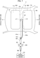
roof forming opening 12a on the facing side. - A second power feeding point n12 is provided to the long side L3 of the first sun
roof forming opening 12b on the facing side. - The hot-
side conducting wire 101a is connected to the first power feeding point n11. - The earth-
side conducting wire 102a is connected to the second power feeding point n12. - More specifically, as illustrated in
FIG. 7 , the hot-side conducting wire 101a is connected to the one side of thecore wire 101 of theco-axial cable 100 laid in the space formed between theroof 10 and theceiling plate 15 of the vehicle V. - The earth-
side conducting wire 102a is connected to theouter cover wire 102 of theco-axial cable 100. Theouter cover wire 102 of theco-axial cable 100 is earth-connected to the predetermined conductive portion of the vehicle body B by the fixingmetal fitting 250 and thescrew 251. - As illustrated in
FIG. 5 given above, the hot-side conducting wire 101a and the earth-side conducting wire 102a can be attached to the vehicle inner side of the roof 10 (the side facing the ceiling plate 15) through intermediation of the terminal metal fittings T1 and T2 each having thebolt insertion hole 160. - The other end of the
core wire 101 is connected to thesignal processing device 300 or the like provided to the vehicle V. - In order to improve antenna characteristics, it is desired that the hot-
side conducting wire 101a and the earth-side conducting wire 102a have the same length. - As described above, with the vehicle antenna A2 according to this embodiment, the sun roofs SRI and SR2 formed at the one location of the
roof 10 of the vehicle V can be provided with an antenna function as a slot antenna without obstructing a visual field of a passenger. - The vehicle antenna and the like of the present invention are described above based on the illustrated embodiments. However, the present invention is not limited thereto, and the configurations of the respective elements may be replaced with freely-selected configurations having similar functions.
- The entire contents of
Japanese patent application No. 2019-081760 (filed on April 23, 2019 - While the embodiments of the present invention are described, these embodiments are presented by way of example only, and are not intended to limit the scope of the invention. The novel embodiments described herein may be embodied in a variety of other forms, and various omissions, substitutions, and changes may be made without departing from the spirit of the invention. The embodiments and the modifications thereof fall within the scope and the spirit of the invention, and fall within the scope of the invention and the equivalents thereof described in the claims.
Claims (3)
- A vehicle antenna applied to a vehicle including a sun roof, the vehicle antenna comprising:a sun roof forming opening exhibiting a rectangular shape at one location on a roof of the vehicle, the roof being formed of a conductive material;a first power feeding point provided to one long side of the sun roof forming opening;a second power feeding point provided to another long side of the sun roof forming opening;a hot-side conducting wire connected to the first power feeding point; andan earth-side conducting wire connected to the second power feeding point.
- A vehicle antenna applied to a vehicle including a sun roof, the vehicle antenna comprising:a first sun roof forming opening and a second sun roof forming opening exhibiting a rectangular shape and being formed, on a roof of the vehicle, in parallel to have long sides facing each other, the roof being formed of a conductive material;a first power feeding point provided to a long side of the first sun roof forming opening on a facing side;a second power feeding point provided to a long side of the second sun roof forming opening on a facing side;a hot-side conducting wire connected to the first power feeding point; andan earth-side conducting wire connected to the second power feeding point.
- The vehicle antenna according to claim 1 or 2, whereinthe hot-side conducting wire is connected to one end of a core wire of a co-axial cable laid in the vehicle,the earth-side conducting wire is connected to an outer cover wire of the co-axial cable,another end of the core wire is connected to a signal processing device provided to the vehicle, andthe outer cover wire is earth-connected to a conductive portion of a vehicle body.
Applications Claiming Priority (2)
| Application Number | Priority Date | Filing Date | Title |
|---|---|---|---|
| JP2019081760A JP6936276B2 (en) | 2019-04-23 | 2019-04-23 | Vehicle antenna |
| PCT/JP2020/016574 WO2020218115A1 (en) | 2019-04-23 | 2020-04-15 | Antenna for vehicle |
Publications (2)
| Publication Number | Publication Date |
|---|---|
| EP3961809A1 true EP3961809A1 (en) | 2022-03-02 |
| EP3961809A4 EP3961809A4 (en) | 2022-05-18 |
Family
ID=72941974
Family Applications (1)
| Application Number | Title | Priority Date | Filing Date |
|---|---|---|---|
| EP20796197.0A Withdrawn EP3961809A4 (en) | 2019-04-23 | 2020-04-15 | ANTENNA FOR VEHICLES |
Country Status (5)
| Country | Link |
|---|---|
| US (1) | US11855339B2 (en) |
| EP (1) | EP3961809A4 (en) |
| JP (1) | JP6936276B2 (en) |
| CN (1) | CN113632317B (en) |
| WO (1) | WO2020218115A1 (en) |
Families Citing this family (1)
| Publication number | Priority date | Publication date | Assignee | Title |
|---|---|---|---|---|
| CN112909498B (en) | 2021-02-09 | 2022-11-18 | 福耀玻璃工业集团股份有限公司 | Antenna module, antenna system and vehicle |
Family Cites Families (16)
| Publication number | Priority date | Publication date | Assignee | Title |
|---|---|---|---|---|
| JPH0226808U (en) * | 1988-08-08 | 1990-02-21 | ||
| JPH03220802A (en) * | 1990-01-26 | 1991-09-30 | Pioneer Electron Corp | Microstrip antenna |
| JPH059012U (en) | 1991-07-09 | 1993-02-05 | 株式会社城南製作所 | Car antenna |
| US6320544B1 (en) * | 2000-04-06 | 2001-11-20 | Lucent Technologies Inc. | Method of producing desired beam widths for antennas and antenna arrays in single or dual polarization |
| DE10141583B4 (en) * | 2001-08-24 | 2014-02-13 | Heinz Lindenmeier | Antenna arrangement in the aperture of an electrically conductive vehicle body |
| JP2003249812A (en) * | 2002-02-22 | 2003-09-05 | Toyota Central Res & Dev Lab Inc | Antenna device and vehicle equipped with the antenna device |
| JP4114430B2 (en) * | 2002-08-06 | 2008-07-09 | 株式会社豊田中央研究所 | antenna |
| JP3925364B2 (en) * | 2002-09-03 | 2007-06-06 | 株式会社豊田中央研究所 | Antenna and diversity receiver |
| CN101246988B (en) * | 2007-02-13 | 2013-06-05 | 中山大学 | An ultra-broadband short-circuit dipole antenna |
| US7868835B2 (en) * | 2008-09-02 | 2011-01-11 | Kathrein-Werke Kg | Beam shaping means for external and/or roof antennas on vehicles, and associated antenna |
| JP5477377B2 (en) * | 2009-03-30 | 2014-04-23 | 日本電気株式会社 | Slot antenna, electronic device, and method for manufacturing slot antenna |
| JP5441793B2 (en) * | 2010-03-30 | 2014-03-12 | 日本板硝子株式会社 | Glass antenna |
| BR112014007469B1 (en) | 2011-09-27 | 2022-06-14 | Janssen Biotech, Inc | MANUFACTURING METHOD OF A LIBRARY OF TYPE III FIBRONECTIN MODULE DOMAINS (FN3), LIBRARY AND METHOD TO OBTAIN A PROTEIN FRAMEWORK |
| DE102014016851B3 (en) * | 2014-11-13 | 2015-12-10 | Kathrein-Werke Kg | MIMO slot antenna for motor vehicles |
| JP2018083432A (en) * | 2016-11-21 | 2018-05-31 | アイシン精機株式会社 | Vehicle roof device |
| CN106684560A (en) * | 2016-11-29 | 2017-05-17 | 广东工业大学 | A Beautified Slot Dipole Antenna |
-
2019
- 2019-04-23 JP JP2019081760A patent/JP6936276B2/en active Active
-
2020
- 2020-04-15 CN CN202080024854.7A patent/CN113632317B/en active Active
- 2020-04-15 EP EP20796197.0A patent/EP3961809A4/en not_active Withdrawn
- 2020-04-15 WO PCT/JP2020/016574 patent/WO2020218115A1/en not_active Ceased
-
2021
- 2021-09-27 US US17/485,738 patent/US11855339B2/en active Active
Also Published As
| Publication number | Publication date |
|---|---|
| JP2020182012A (en) | 2020-11-05 |
| CN113632317B (en) | 2024-03-26 |
| EP3961809A4 (en) | 2022-05-18 |
| WO2020218115A1 (en) | 2020-10-29 |
| US20220013887A1 (en) | 2022-01-13 |
| US11855339B2 (en) | 2023-12-26 |
| JP6936276B2 (en) | 2021-09-15 |
| CN113632317A (en) | 2021-11-09 |
Similar Documents
| Publication | Publication Date | Title |
|---|---|---|
| US10903555B2 (en) | Antenna system and side mirror for a vehicle incorporating said antenna | |
| JP5487938B2 (en) | Composite antenna device for vehicle | |
| US12046807B2 (en) | Antenna device for vehicle | |
| EP3352297A1 (en) | Antenna device | |
| US10374314B2 (en) | Composite patch antenna device | |
| CN102290634A (en) | In-vehicle antenna system and method | |
| JP2008271551A (en) | Multiband antenna device for automobile | |
| US11855339B2 (en) | Vehicle antenna | |
| US8289217B2 (en) | In-vehicle antenna system and method | |
| US9276645B2 (en) | Inductive charger for providing radio frequency (“RF”) signal to a portable electric device | |
| JP2017060038A (en) | Antenna and vehicle using it | |
| JP6031057B2 (en) | Antenna device | |
| JP2013026828A (en) | Glass antenna for vehicle | |
| JP3048483B2 (en) | Antenna integrated receiver and receiving board | |
| JP2003249812A (en) | Antenna device and vehicle equipped with the antenna device | |
| Bras et al. | Omnidirectional printed loop antenna for taxi communications | |
| EP3961804B1 (en) | Vehicle antenna | |
| US20150318605A1 (en) | Co-linear am/fm and dsrc antenna | |
| JP4461066B2 (en) | Compound antenna device | |
| CN214754134U (en) | Integrated T-BOX 5G panel antenna | |
| CN112219312A (en) | In-vehicle wireless system | |
| JP4788895B2 (en) | Antenna device | |
| WO2011074419A1 (en) | Antenna | |
| KR102145992B1 (en) | Vehicle and antena | |
| JP3031936U (en) | Small in-vehicle antenna for TV |
Legal Events
| Date | Code | Title | Description |
|---|---|---|---|
| STAA | Information on the status of an ep patent application or granted ep patent |
Free format text: STATUS: THE INTERNATIONAL PUBLICATION HAS BEEN MADE |
|
| PUAI | Public reference made under article 153(3) epc to a published international application that has entered the european phase |
Free format text: ORIGINAL CODE: 0009012 |
|
| STAA | Information on the status of an ep patent application or granted ep patent |
Free format text: STATUS: REQUEST FOR EXAMINATION WAS MADE |
|
| 17P | Request for examination filed |
Effective date: 20210927 |
|
| AK | Designated contracting states |
Kind code of ref document: A1 Designated state(s): AL AT BE BG CH CY CZ DE DK EE ES FI FR GB GR HR HU IE IS IT LI LT LU LV MC MK MT NL NO PL PT RO RS SE SI SK SM TR |
|
| A4 | Supplementary search report drawn up and despatched |
Effective date: 20220422 |
|
| RIC1 | Information provided on ipc code assigned before grant |
Ipc: H01Q 13/10 20060101ALI20220414BHEP Ipc: H01Q 1/32 20060101AFI20220414BHEP |
|
| STAA | Information on the status of an ep patent application or granted ep patent |
Free format text: STATUS: THE APPLICATION HAS BEEN WITHDRAWN |
|
| 18W | Application withdrawn |
Effective date: 20220621 |