EP3961800A1 - Battery and battery pack - Google Patents
Battery and battery pack Download PDFInfo
- Publication number
- EP3961800A1 EP3961800A1 EP21193317.1A EP21193317A EP3961800A1 EP 3961800 A1 EP3961800 A1 EP 3961800A1 EP 21193317 A EP21193317 A EP 21193317A EP 3961800 A1 EP3961800 A1 EP 3961800A1
- Authority
- EP
- European Patent Office
- Prior art keywords
- tab
- pole core
- lead
- out position
- solder joint
- Prior art date
- Legal status (The legal status is an assumption and is not a legal conclusion. Google has not performed a legal analysis and makes no representation as to the accuracy of the status listed.)
- Pending
Links
Images


Classifications
-
- H—ELECTRICITY
- H01—ELECTRIC ELEMENTS
- H01M—PROCESSES OR MEANS, e.g. BATTERIES, FOR THE DIRECT CONVERSION OF CHEMICAL ENERGY INTO ELECTRICAL ENERGY
- H01M50/00—Constructional details or processes of manufacture of the non-active parts of electrochemical cells other than fuel cells, e.g. hybrid cells
- H01M50/50—Current conducting connections for cells or batteries
- H01M50/531—Electrode connections inside a battery casing
- H01M50/533—Electrode connections inside a battery casing characterised by the shape of the leads or tabs
-
- H—ELECTRICITY
- H01—ELECTRIC ELEMENTS
- H01M—PROCESSES OR MEANS, e.g. BATTERIES, FOR THE DIRECT CONVERSION OF CHEMICAL ENERGY INTO ELECTRICAL ENERGY
- H01M50/00—Constructional details or processes of manufacture of the non-active parts of electrochemical cells other than fuel cells, e.g. hybrid cells
- H01M50/50—Current conducting connections for cells or batteries
- H01M50/531—Electrode connections inside a battery casing
- H01M50/538—Connection of several leads or tabs of wound or folded electrode stacks
-
- H—ELECTRICITY
- H01—ELECTRIC ELEMENTS
- H01M—PROCESSES OR MEANS, e.g. BATTERIES, FOR THE DIRECT CONVERSION OF CHEMICAL ENERGY INTO ELECTRICAL ENERGY
- H01M10/00—Secondary cells; Manufacture thereof
- H01M10/05—Accumulators with non-aqueous electrolyte
- H01M10/058—Construction or manufacture
- H01M10/0585—Construction or manufacture of accumulators having only flat construction elements, i.e. flat positive electrodes, flat negative electrodes and flat separators
-
- H—ELECTRICITY
- H01—ELECTRIC ELEMENTS
- H01M—PROCESSES OR MEANS, e.g. BATTERIES, FOR THE DIRECT CONVERSION OF CHEMICAL ENERGY INTO ELECTRICAL ENERGY
- H01M10/00—Secondary cells; Manufacture thereof
- H01M10/05—Accumulators with non-aqueous electrolyte
- H01M10/058—Construction or manufacture
- H01M10/0587—Construction or manufacture of accumulators having only wound construction elements, i.e. wound positive electrodes, wound negative electrodes and wound separators
-
- H—ELECTRICITY
- H01—ELECTRIC ELEMENTS
- H01M—PROCESSES OR MEANS, e.g. BATTERIES, FOR THE DIRECT CONVERSION OF CHEMICAL ENERGY INTO ELECTRICAL ENERGY
- H01M50/00—Constructional details or processes of manufacture of the non-active parts of electrochemical cells other than fuel cells, e.g. hybrid cells
- H01M50/10—Primary casings; Jackets or wrappings
- H01M50/147—Lids or covers
- H01M50/166—Lids or covers characterised by the methods of assembling casings with lids
- H01M50/169—Lids or covers characterised by the methods of assembling casings with lids by welding, brazing or soldering
-
- H—ELECTRICITY
- H01—ELECTRIC ELEMENTS
- H01M—PROCESSES OR MEANS, e.g. BATTERIES, FOR THE DIRECT CONVERSION OF CHEMICAL ENERGY INTO ELECTRICAL ENERGY
- H01M50/00—Constructional details or processes of manufacture of the non-active parts of electrochemical cells other than fuel cells, e.g. hybrid cells
- H01M50/50—Current conducting connections for cells or batteries
- H01M50/531—Electrode connections inside a battery casing
- H01M50/536—Electrode connections inside a battery casing characterised by the method of fixing the leads to the electrodes, e.g. by welding
-
- H—ELECTRICITY
- H01—ELECTRIC ELEMENTS
- H01M—PROCESSES OR MEANS, e.g. BATTERIES, FOR THE DIRECT CONVERSION OF CHEMICAL ENERGY INTO ELECTRICAL ENERGY
- H01M50/00—Constructional details or processes of manufacture of the non-active parts of electrochemical cells other than fuel cells, e.g. hybrid cells
- H01M50/50—Current conducting connections for cells or batteries
- H01M50/531—Electrode connections inside a battery casing
- H01M50/54—Connection of several leads or tabs of plate-like electrode stacks, e.g. electrode pole straps or bridges
-
- Y—GENERAL TAGGING OF NEW TECHNOLOGICAL DEVELOPMENTS; GENERAL TAGGING OF CROSS-SECTIONAL TECHNOLOGIES SPANNING OVER SEVERAL SECTIONS OF THE IPC; TECHNICAL SUBJECTS COVERED BY FORMER USPC CROSS-REFERENCE ART COLLECTIONS [XRACs] AND DIGESTS
- Y02—TECHNOLOGIES OR APPLICATIONS FOR MITIGATION OR ADAPTATION AGAINST CLIMATE CHANGE
- Y02E—REDUCTION OF GREENHOUSE GAS [GHG] EMISSIONS, RELATED TO ENERGY GENERATION, TRANSMISSION OR DISTRIBUTION
- Y02E60/00—Enabling technologies; Technologies with a potential or indirect contribution to GHG emissions mitigation
- Y02E60/10—Energy storage using batteries
-
- Y—GENERAL TAGGING OF NEW TECHNOLOGICAL DEVELOPMENTS; GENERAL TAGGING OF CROSS-SECTIONAL TECHNOLOGIES SPANNING OVER SEVERAL SECTIONS OF THE IPC; TECHNICAL SUBJECTS COVERED BY FORMER USPC CROSS-REFERENCE ART COLLECTIONS [XRACs] AND DIGESTS
- Y02—TECHNOLOGIES OR APPLICATIONS FOR MITIGATION OR ADAPTATION AGAINST CLIMATE CHANGE
- Y02P—CLIMATE CHANGE MITIGATION TECHNOLOGIES IN THE PRODUCTION OR PROCESSING OF GOODS
- Y02P70/00—Climate change mitigation technologies in the production process for final industrial or consumer products
- Y02P70/50—Manufacturing or production processes characterised by the final manufactured product
Definitions
- the present invention relates to the field of batteries, and in particular, to a battery and a battery pack having same.
- a plurality of tabs of a pole core are converged and then soldered together.
- the position of the solder joint affects the length of the tab free region.
- the movable length of the tab is increased, and a larger bending space is required in order to accommodate the tab.
- the larger bending space leads to capacity loss of the cell. If the bending space is not increased, the tab will be compressed, which is likely to cause the positive and negative electrodes to come into contact with each other, endangering the safety of the battery.
- an objective of the present invention is to propose a battery, which can prevent the tab from being pulled after bending, can avoid the capacity loss of the cell, and can also prevent the tab from being compressed. thereby improving the safety of the battery.
- the battery according to the present invention includes a cell, where the cell has at least one pole core, each pole core has a plurality of tabs, the plurality of tabs are converged and then soldered to a cover plate of the battery to form a solder joint, and when the pole core is parallel to the cover plate before convergence or after the pole core is unfolded, a spacing between the pole core and the solder joint is determined by a thickness of the pole core, a tab bending angle of one or more tab the plurality of tabs, and a width of a tab protection plate at the solder joint.
- the battery according to the present invention offers a more desirable spacing between the pole core and the solder joint, which can prevent the tab from being pulled after bending, and can prevent the tab from being torn, so as to avoid capacity loss of the cell; and also offers a desirable movable length of the tab and a desirable bending space, so as to avoid capacity loss of the cell, and prevent the tab from being compressed, thereby improving the safety of the battery in use.
- the spacing between the pole core and the solder joint is L 1
- the thickness of the pole core is D
- the width of the tab protection plate is d 1
- a tab free region is formed between the pole core and the solder joint, and a length of the tab free region is determined by a tab lead-out manner of the pole core.
- the term 'tab free region' as used in the present application refers to a free region of the plurality of tabs, i.e. a region in which the tabs extend without out being (directly) restricted and/or fixed by the pole core or the solder joint.
- the term 'tab free region' the term 'bending space' or 'bending space of the tabs" can be used, as the tab free region is the region in which the tabs bend between their restriction/fixation at the pole core and the solder joint.
- the pole core is constructed as a wound pole core, and when the tab extends out from the pole core in a tab semi-lead-out manner, the thickness of the pole core is D, a length by which the tab extends out from the pole core in an extension direction of the tab is L 2 , the length of the tab free region is L 3 , and the following relational expression is satisfied: 0.25D ⁇ L 3 ⁇ L 2 .
- the thickness of the pole core is D
- a length by which the tab extends out from the pole core in an extension direction of the tab is L 2
- the length of the tab free region is L 3
- the following relational expression is satisfied: 0.5D ⁇ L 3 ⁇ L 2 .
- the plurality of tabs converge and form a tab converging and lead-out position, and in a thickness direction of the pole core, the tab converging and lead-out position includes a zero lead-out position, an intermediate lead-out position, and a biased lead-out position; and the tab converging and lead-out position is located at the zero lead-out position or the biased lead-out position.
- the plurality of tabs converge and form a tab converging and lead-out position, and in a thickness direction of the pole core, the tab converging and lead-out position includes a zero lead-out position, an intermediate lead-out position, and a biased lead-out position; and the tab converging and lead-out position is located at the intermediate lead-out position.
- the width of the tab protection plate is 8-12 mm.
- the solder joint is disposed in a solder joint region of the tab, the solder joint region includes an ultrasonic soldering region and a laser soldering region, and the laser soldering region is located inside the ultrasonic soldering region.
- a width of the ultrasonic soldering region in the extension direction of the tab is 4-8 mm.
- the battery pack according to the present invention includes the above-mentioned battery.
- a battery 100 according to the embodiments of the present invention will be described below with reference to FIG. 1 to FIG. 5 .
- the battery 100 includes a cell 10.
- the cell 10 has at least one pole core 20.
- Each pole core 20 has a plurality of tabs 201 (lugs).
- the plurality of tabs 201 are converged and then soldered to a cover plate 30 of the battery 100 to form a solder joint 40.
- a spacing between the pole core 20 and the solder joint 40 is determined by a thickness of the pole core 20, a tab bending angle of the tab 201, and a width of a tab protection plate at the solder joint 40 in an extension direction of the tab 201.
- Tab 201 may refer to a tab of the plurality of tabs arranged at an outer part or an outer edge (as seen in the up/down directions in the figures) of the pole core 20. There may be more than one tab having this property.
- the tab protection plate is provided at the solder joint 40.
- Each pole core 20 has a plurality of separators 202. A spacing between an end portion of the separator 202 opposite to the solder joint 40 and the solder joint 40 is determined by the thickness of the pole core 20, the tab bending angle of the tab 201, and the width of the tab protection plate in the extension direction of the tab 201.
- the thickness direction of the pole core 20 refers to a thickness direction of the pole core 20 in FIG. 3 to FIG. 5
- the extension direction of the tab 201 refers to a left-right direction in FIG. 3 to FIG. 5 .
- the present invention offers a more desirable spacing between the pole core 20 and the solder joint 40, which can prevent the tab 201 from being pulled after bending, and can prevent the tab 201 from being torn, so as to avoid the problem that some electrode plates cannot output electricity, and avoid capacity loss of the cell 1 0.
- the present invention also offers a desirable movable length of the tab 201 and a desirable bending space for accommodating the tab 201, so as to avoid capacity loss of the cell 10, and prevent the tab 201 from being compressed to cause the positive and negative electrodes of the cell 10 to come into contact with each other, prevent a short circuit of the cell 10, thereby improving the safety of the battery 100 in use.
- the tab bending angle A of the tab 201 satisfies the following relational expression: 45° ⁇ A ⁇ 135°.
- the spacing between an end portion of the separator 202 of the pole core 20 opposite to the solder joint 40 and the solder joint 40 is L 1 .
- the present invention can further prevent the tab 201 from being pulled after bending, and can prevent the tab 201 from being torn, so as to further avoid the problem that some electrode plates cannot output electricity, and further avoid capacity loss of the cell 10.
- the present invention also offers a more desirable movable length of the tab 201 and a more desirable bending space for accommodating the tab 201, so as to further avoid capacity loss of the cell 10, further prevent the tab 201 from being compressed to cause the positive and negative electrodes of the cell 10 to come into contact with each other, and better prevent a short circuit of the cell 10, thereby improving the safety of the battery 100 in use.
- the width of the tab protection plate may be set to 8-12 mm.
- the present invention offers a desirable width of the tab protection plate, which can protect the tab 201 better, can further prevent the tab 201 from being pulled after bending, and can further prevent the tab 201 from being torn, so as to further avoid the problem that some electrode plates cannot output electricity, and further avoid capacity loss of the cell 10.
- the present invention also offers a more desirable movable length of the tab 201 and a more desirable bending space for accommodating the tab 201, so as to further avoid capacity loss of the cell 10, further prevent the tab 201 from being compressed to cause the positive and negative electrodes of the cell 10 to come into contact with each other, and better prevent a short circuit of the cell 10, thereby improving the safety of the battery 100 in use.
- a tab free region is formed between the pole core 20 and the solder joint 40.
- the tab free region is formed between the end portion of separator 202 opposite to the solder joint 40 and the solder joint 40, and the length of the tab free region is determined by the lead-out manner of the tab 201 of the pole core 20.
- the present invention offers a more desirable length of the tab free region, which can further prevent the tab 201 from being pulled after bending, and can further avoid the problem that some electrode plates cannot output electricity, and further avoid capacity loss of the cell 10.
- the present invention also offers a more desirable movable length of the tab 201 and a more desirable bending space for accommodating the tab 201, so as to further avoid capacity loss of the cell 10, further prevent the tab 201 from being compressed to cause the positive and negative electrodes of the cell 10 to come into contact with each other, and better prevent a short circuit of the cell 10, thereby improving the safety of the battery 100 in use.
- a more desirable bending angle of the tab 201 can be ensured.
- the pole core 20 is constructed as a wound pole core 20, and when the tab 201 extends out from the pole core 20 in a tab semi-lead-out manner (where it should be noted that the tab semi-lead-out manner means that only one tab 201 is led out for each turn of the pole core 20 after the pole core 20 is wound, and the tab semi-lead-out manner is only applicable to a wound pole core 20), the thickness of the pole core 20 is D, a length by which the tab 201 extends out from the pole core 20 in the extension direction of the tab 201 is L 2 (which can also be understood as that a length by which the tab 201 extends out from the separator 202 in the extension direction of the tab 201 is L 2 ), the length of the tab free region is L 3 , and the following relational expression is satisfied: 0.25D ⁇ L 3 ⁇ L 2 .
- such a setting offers a desirable length of the tab free region, which can prevent the tab 201 from being torn, can prevent the tab 201 from being compressed, and can reduce the risk of short circuit in the cell 10.
- the plurality of tabs 201 converge and form a tab converging and lead-out position, and in a thickness direction of the pole core 20, the tab converging and lead-out position may include a zero lead-out position 50, an intermediate lead-out position 60, and a biased lead-out position 70.
- the tab converging and lead-out position may be located at the zero lead-out position 50.
- the tab converging and lead-out position may be located at the biased lead-out position 70.
- the intermediate lead-out position 60 coincides with a central axis 80 of the pole core.
- the zero lead-out position 50 is located on an axis where the outermost layer of the pole core 20 is located.
- the biased lead-out position 70 is located between the zero lead-out position 50 and the intermediate lead-out position 60.
- Such a setting offers a desirable tab bending angle of the tab 201 suitable, and can ensure that the tab 201 does not compress the separator 202, so as to reduce the risk of damage of the separator 202, thereby reducing the risk of short circuit in the cell 10, and can improve the safety of the battery 100 in use.
- the tab fully-lead-out manner means that when the pole core 20 is a laminated pole core, each electrode plate of the pole core 20 has a tab 201 extending out therefrom; or means that when the pole core 20 is a wound pole core, each turn of electrode plate of the pole core 20 is symmetrically provided with two tabs 201 by taking the diameter of the pole core 20 as the symmetric center; the laminated pole core 20 needs to adopt the tab fully-lead-out manner, and the wound pole core 20 may or may not adopt the tab fully-lead-out manner), the thickness of the pole core 20 is D, a length by which the tab 201 extends out from the pole core 20 in the extension direction of the tab 201 is L 2 (which can also be understood as that a length by which the tab 201 extends out from the separator 202 in the extension direction of the
- the plurality of tabs 201 converge and form a tab converging and lead-out position, and in a thickness direction of the pole core 20, the tab converging and lead-out position includes a zero lead-out position 50, an intermediate lead-out position 60, and a biased lead-out position 70. As shown in FIG. 5 , the tab converging and lead-out position may be located at the intermediate lead-out position 60.
- Such a setting offers a desirable tab bending angle of the tab 201 suitable, and can ensure that the tab 201 does not compress the separator 202, so as to reduce the risk of damage of the separator 202, thereby reducing the risk of short circuit in the cell 10, and can improve the safety of the battery 100 in use.
- the solder joint 40 may be disposed in a solder joint region of the tab 201, the solder joint region may include an ultrasonic soldering region and a laser soldering region, and the laser soldering region is located inside the ultrasonic soldering region. That is, the laser soldering region overlaps with the ultrasonic soldering region.
- the plurality of tabs 201 are first soldered together in the ultrasonic soldering region by ultrasonic soldering, and the plurality of tabs 201 are converged. Then the converged tabs 201 are soldered on the cover plate 30 in the laser soldering region by laser soldering.
- the plurality of tabs 201 can be reliably soldered to the cover plate 30, and can prevent the plurality of tabs 201 from being separated from the cover plate 30, thereby ensuring the working reliability of the battery 100.
- a width of the ultrasonic soldering region in the extension direction of the tab 201 is 4-8 mm.
- the width of the ultrasonic soldering region is set to 6 mm.
- Such a setting offers a desirable width of the ultrasonic soldering region can reliably solder together the plurality of tabs 201, and can also ensure the soldering quality.
- the spacing between the pole core 20 and the solder joint refers to a spacing from the pole core 20 to the center of the laser soldering joint.
- the battery pack according to the embodiments of the present invention includes the battery 100 of the above embodiments, and disposing the battery 100 in the battery pack offers a more desirable spacing between the pole core 20 and the solder joint 40, which can prevent the tab 201 from being pulled after bending, and can prevent the tab 201 from being torn, so as to avoid capacity loss of the cell 10; and also offers a desirable movable length of the tab 201 and a desirable bending space, so as to avoid capacity loss of the cell 10, and prevent the tab 201 from being compressed, thereby improving the safety of the battery 100 in use.
Landscapes
- Chemical & Material Sciences (AREA)
- Chemical Kinetics & Catalysis (AREA)
- Electrochemistry (AREA)
- General Chemical & Material Sciences (AREA)
- Engineering & Computer Science (AREA)
- Manufacturing & Machinery (AREA)
- Connection Of Batteries Or Terminals (AREA)
Abstract
Description
- The present invention relates to the field of batteries, and in particular, to a battery and a battery pack having same.
- In the related art, a plurality of tabs of a pole core are converged and then soldered together. The position of the solder joint affects the length of the tab free region. When the pole core is parallel to the cover plate before convergence or after the pole core is unfolded, if the spacing between the pole core and the mid-point position of the solder joint is designed too small, the tab is easily pulled after bending, which causes the tab to be torn, resulting in that some electrode plates cannot output electricity, leading to capacity loss of the cell.
- If the spacing between the pole core and the mid-point position of the solder joint is designed too large, the movable length of the tab is increased, and a larger bending space is required in order to accommodate the tab. However, the larger bending space leads to capacity loss of the cell. If the bending space is not increased, the tab will be compressed, which is likely to cause the positive and negative electrodes to come into contact with each other, endangering the safety of the battery.
- The present invention aims to resolve at least one of the technical problems existing in the prior art. In view of this, an objective of the present invention is to propose a battery, which can prevent the tab from being pulled after bending, can avoid the capacity loss of the cell, and can also prevent the tab from being compressed. thereby improving the safety of the battery.
- The invention is set out in the appended set of claims. Provided are a battery and a battery pack according to the independent claims; dependent claims relate to preferred embodiments..
- The battery according to the present invention includes a cell, where the cell has at least one pole core, each pole core has a plurality of tabs, the plurality of tabs are converged and then soldered to a cover plate of the battery to form a solder joint, and when the pole core is parallel to the cover plate before convergence or after the pole core is unfolded, a spacing between the pole core and the solder joint is determined by a thickness of the pole core, a tab bending angle of one or more tab the plurality of tabs, and a width of a tab protection plate at the solder joint.
- The battery according to the present invention offers a more desirable spacing between the pole core and the solder joint, which can prevent the tab from being pulled after bending, and can prevent the tab from being torn, so as to avoid capacity loss of the cell; and also offers a desirable movable length of the tab and a desirable bending space, so as to avoid capacity loss of the cell, and prevent the tab from being compressed, thereby improving the safety of the battery in use.
- Preferably, the spacing between the pole core and the solder joint is L1, the thickness of the pole core is D, the width of the tab protection plate is d1, the tab bending angle of the one or more tab is A, and the following relational expression is satisfied: L1=D/2*tanA+d1/2.
- More preferably, 45°≤A≤135°.
- Preferably, when the pole core is parallel to the cover plate before convergence or after the pole core is unfolded, a tab free region is formed between the pole core and the solder joint, and a length of the tab free region is determined by a tab lead-out manner of the pole core. The term 'tab free region' as used in the present application refers to a free region of the plurality of tabs, i.e. a region in which the tabs extend without out being (directly) restricted and/or fixed by the pole core or the solder joint. Instead of the term 'tab free region' the term 'bending space' or 'bending space of the tabs" can be used, as the tab free region is the region in which the tabs bend between their restriction/fixation at the pole core and the solder joint.
- Preferably, the pole core is constructed as a wound pole core, and when the tab extends out from the pole core in a tab semi-lead-out manner, the thickness of the pole core is D, a length by which the tab extends out from the pole core in an extension direction of the tab is L2, the length of the tab free region is L3, and the following relational expression is satisfied: 0.25D<L3<L2.
- Preferably, when the tab extends out from the pole core in a tab fully-lead-out manner, the thickness of the pole core is D, a length by which the tab extends out from the pole core in an extension direction of the tab is L2, the length of the tab free region is L3, and the following relational expression is satisfied: 0.5D<L3<L2.
- Preferably, the plurality of tabs converge and form a tab converging and lead-out position, and in a thickness direction of the pole core, the tab converging and lead-out position includes a zero lead-out position, an intermediate lead-out position, and a biased lead-out position; and the tab converging and lead-out position is located at the zero lead-out position or the biased lead-out position.
- Preferably, the plurality of tabs converge and form a tab converging and lead-out position, and in a thickness direction of the pole core, the tab converging and lead-out position includes a zero lead-out position, an intermediate lead-out position, and a biased lead-out position; and the tab converging and lead-out position is located at the intermediate lead-out position.
- Preferably, the width of the tab protection plate is 8-12 mm.
- Preferably, the solder joint is disposed in a solder joint region of the tab, the solder joint region includes an ultrasonic soldering region and a laser soldering region, and the laser soldering region is located inside the ultrasonic soldering region.
- In some examples of the present invention, a width of the ultrasonic soldering region in the extension direction of the tab is 4-8 mm.
- The battery pack according to the present invention includes the above-mentioned battery.
- The additional aspects and advantages of the present invention will be set forth in part in the description below, parts of which will become apparent from the description below, or will be understood by the practice of the present invention.
- These and other aspects and advantages of the present invention will become apparent and more readily appreciated from the following descriptions made with reference to the drawings, in which:
-
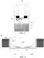
FIG. 1 is a cross-sectional view of a battery according to an embodiment of the present invention; -
FIG. 2 is a schematic diagram of a battery according to an embodiment of the present invention when the pole core is parallel to the cover plate after the pole core is unfolded; -
FIG. 3 is a schematic diagram showing that the pole core of the battery is located at the zero lead-out position according to an embodiment of the present invention; -
FIG. 4 is a schematic diagram showing that the pole core of the battery is located at the biased lead-out position according to an embodiment of the present invention; and -
FIG. 5 is a schematic diagram showing that the pole core of the battery is located at the intermediate lead-out position according to an embodiment of the present invention. - Reference numerals:
-
battery 100; -
cell 10; -
pole core 20;tab 201;separator 202; -
cover plate 30; -
solder joint 40; - zero lead-
out position 50; intermediate lead-out position 60; biased lead-out position 70; pole corecentral axis 80; - Detailed description of the embodiments of the present invention will be made in the following, and examples thereof are illustrated in the drawings, throughout which identical or similar elements or elements of identical or similar functions are represented with identical or similar reference numerals. The embodiments that are described with reference to the accompanying drawings are exemplary, and are only used to interpret the present invention, instead limiting the present invention.
- A
battery 100 according to the embodiments of the present invention will be described below with reference toFIG. 1 to FIG. 5 . - As shown in
FIG. 1 to FIG. 5 , thebattery 100 includes acell 10. Thecell 10 has at least onepole core 20. Eachpole core 20 has a plurality of tabs 201 (lugs). The plurality oftabs 201 are converged and then soldered to acover plate 30 of thebattery 100 to form asolder joint 40. When thepole core 20 is parallel to thecover plate 30 before convergence or after thepole core 20 is unfolded, which may be understood as that when thepole core 20 is parallel to thecover plate 30 before convergence or when thepole core 20 is parallel to thecover plate 30 after being unfolded, a spacing between thepole core 20 and thesolder joint 40 is determined by a thickness of thepole core 20, a tab bending angle of thetab 201, and a width of a tab protection plate at thesolder joint 40 in an extension direction of thetab 201.Tab 201 may refer to a tab of the plurality of tabs arranged at an outer part or an outer edge (as seen in the up/down directions in the figures) of thepole core 20. There may be more than one tab having this property. - The tab protection plate is provided at the
solder joint 40. Eachpole core 20 has a plurality ofseparators 202. A spacing between an end portion of theseparator 202 opposite to thesolder joint 40 and thesolder joint 40 is determined by the thickness of thepole core 20, the tab bending angle of thetab 201, and the width of the tab protection plate in the extension direction of thetab 201. It should be noted that the thickness direction of thepole core 20 refers to a thickness direction of thepole core 20 inFIG. 3 to FIG. 5 , and the extension direction of thetab 201 refers to a left-right direction inFIG. 3 to FIG. 5 . - By determining the spacing between the
pole core 20 and thesolder joint 40 according to the thickness of thepole core 20, the tab bending angle of thetab 201, and the width of the tab protection plate at thesolder joint 40 in the extension direction of thetab 201, the present invention offers a more desirable spacing between thepole core 20 and thesolder joint 40, which can prevent thetab 201 from being pulled after bending, and can prevent thetab 201 from being torn, so as to avoid the problem that some electrode plates cannot output electricity, and avoid capacity loss of the cell 1 0. The present invention also offers a desirable movable length of thetab 201 and a desirable bending space for accommodating thetab 201, so as to avoid capacity loss of thecell 10, and prevent thetab 201 from being compressed to cause the positive and negative electrodes of thecell 10 to come into contact with each other, prevent a short circuit of thecell 10, thereby improving the safety of thebattery 100 in use. - In some embodiments, the spacing between the
pole core 20 and thesolder joint 40 is L1, the thickness of thepole core 20 is D, the width of the tab protection plate is d1, the tab bending angle of thetab 201 is A, and the following relational expression is satisfied: L1=D/2*tanA+d1/2. The tab bending angle A of thetab 201 satisfies the following relational expression: 45°≤A≤135°. The spacing between an end portion of theseparator 202 of thepole core 20 opposite to thesolder joint 40 and thesolder joint 40 is L1. By such a setting, the present invention can further prevent thetab 201 from being pulled after bending, and can prevent thetab 201 from being torn, so as to further avoid the problem that some electrode plates cannot output electricity, and further avoid capacity loss of thecell 10. The present invention also offers a more desirable movable length of thetab 201 and a more desirable bending space for accommodating thetab 201, so as to further avoid capacity loss of thecell 10, further prevent thetab 201 from being compressed to cause the positive and negative electrodes of thecell 10 to come into contact with each other, and better prevent a short circuit of thecell 10, thereby improving the safety of thebattery 100 in use. - In some embodiments, the width of the tab protection plate may be set to 8-12 mm. By such a setting, the present invention offers a desirable width of the tab protection plate, which can protect the
tab 201 better, can further prevent thetab 201 from being pulled after bending, and can further prevent thetab 201 from being torn, so as to further avoid the problem that some electrode plates cannot output electricity, and further avoid capacity loss of thecell 10. The present invention also offers a more desirable movable length of thetab 201 and a more desirable bending space for accommodating thetab 201, so as to further avoid capacity loss of thecell 10, further prevent thetab 201 from being compressed to cause the positive and negative electrodes of thecell 10 to come into contact with each other, and better prevent a short circuit of thecell 10, thereby improving the safety of thebattery 100 in use. - In some embodiments, when the
pole core 20 is parallel to thecover plate 30 before convergence or after thepole core 20 is unfolded, which may be understood as that when thepole core 20 is parallel to thecover plate 30 before convergence or when thepole core 20 is parallel to thecover plate 30 after being unfolded, as shown inFIG. 2 , in the extension direction of thetab 201, a tab free region is formed between thepole core 20 and thesolder joint 40. Specifically, after the plurality oftabs 201 are converged, the tab free region is formed between the end portion ofseparator 202 opposite to the solder joint 40 and the solder joint 40, and the length of the tab free region is determined by the lead-out manner of thetab 201 of thepole core 20. By such a setting, the present invention offers a more desirable length of the tab free region, which can further prevent thetab 201 from being pulled after bending, and can further avoid the problem that some electrode plates cannot output electricity, and further avoid capacity loss of thecell 10. The present invention also offers a more desirable movable length of thetab 201 and a more desirable bending space for accommodating thetab 201, so as to further avoid capacity loss of thecell 10, further prevent thetab 201 from being compressed to cause the positive and negative electrodes of thecell 10 to come into contact with each other, and better prevent a short circuit of thecell 10, thereby improving the safety of thebattery 100 in use. In addition, a more desirable bending angle of thetab 201 can be ensured. - According to a specific embodiment, as shown in
FIG. 3 and FIG. 4 , thepole core 20 is constructed as awound pole core 20, and when thetab 201 extends out from thepole core 20 in a tab semi-lead-out manner (where it should be noted that the tab semi-lead-out manner means that only onetab 201 is led out for each turn of thepole core 20 after thepole core 20 is wound, and the tab semi-lead-out manner is only applicable to a wound pole core 20), the thickness of thepole core 20 is D, a length by which thetab 201 extends out from thepole core 20 in the extension direction of thetab 201 is L2 (which can also be understood as that a length by which thetab 201 extends out from theseparator 202 in the extension direction of thetab 201 is L2), the length of the tab free region is L3, and the following relational expression is satisfied: 0.25D<L3<L2. After the plurality oftabs 201 are soldered together, such a setting offers a desirable length of the tab free region, which can prevent thetab 201 from being torn, can prevent thetab 201 from being compressed, and can reduce the risk of short circuit in thecell 10. - In some embodiments, the plurality of
tabs 201 converge and form a tab converging and lead-out position, and in a thickness direction of thepole core 20, the tab converging and lead-out position may include a zero lead-out position 50, an intermediate lead-out position 60, and a biased lead-out position 70. As shown inFIG. 3 , the tab converging and lead-out position may be located at the zero lead-out position 50. As shown inFIG. 4 , the tab converging and lead-out position may be located at the biased lead-out position 70. The intermediate lead-out position 60 coincides with acentral axis 80 of the pole core. In the thickness direction of thepole core 20, the zero lead-out position 50 is located on an axis where the outermost layer of thepole core 20 is located. The biased lead-out position 70 is located between the zero lead-out position 50 and the intermediate lead-out position 60. The larger the thickness of thecell 10, the closer the tab converging and lead-out position is to the intermediate lead-out position 60. The smaller the thickness of thecell 10, the closer thetab 201 converging and lead-out position is to the zero lead-out position 50. Such a setting offers a desirable tab bending angle of thetab 201 suitable, and can ensure that thetab 201 does not compress theseparator 202, so as to reduce the risk of damage of theseparator 202, thereby reducing the risk of short circuit in thecell 10, and can improve the safety of thebattery 100 in use. - According to another specific embodiment, as shown in
FIG. 5 , when the tab 201 extends out from the pole core 20 in a tab fully-lead-out manner (where it should be noted that the tab fully-lead-out manner means that when the pole core 20 is a laminated pole core, each electrode plate of the pole core 20 has a tab 201 extending out therefrom; or means that when the pole core 20 is a wound pole core, each turn of electrode plate of the pole core 20 is symmetrically provided with two tabs 201 by taking the diameter of the pole core 20 as the symmetric center; the laminated pole core 20 needs to adopt the tab fully-lead-out manner, and the wound pole core 20 may or may not adopt the tab fully-lead-out manner), the thickness of the pole core 20 is D, a length by which the tab 201 extends out from the pole core 20 in the extension direction of the tab 201 is L2 (which can also be understood as that a length by which the tab 201 extends out from the separator 202 in the extension direction of the tab 201 is L2), the length of the tab free region is L3, and the following relational expression is satisfied: 0.5D<L3<L2. Such a setting offers a desirable length of the tab free region, which can prevent the tab 201 from being torn, can prevent the tab 201 from being compressed, and can reduce the risk of short circuit in the cell 10. - Further, the plurality of
tabs 201 converge and form a tab converging and lead-out position, and in a thickness direction of thepole core 20, the tab converging and lead-out position includes a zero lead-out position 50, an intermediate lead-out position 60, and a biased lead-out position 70. As shown inFIG. 5 , the tab converging and lead-out position may be located at the intermediate lead-out position 60. Such a setting offers a desirable tab bending angle of thetab 201 suitable, and can ensure that thetab 201 does not compress theseparator 202, so as to reduce the risk of damage of theseparator 202, thereby reducing the risk of short circuit in thecell 10, and can improve the safety of thebattery 100 in use. - In some embodiments, the solder joint 40 may be disposed in a solder joint region of the
tab 201, the solder joint region may include an ultrasonic soldering region and a laser soldering region, and the laser soldering region is located inside the ultrasonic soldering region. That is, the laser soldering region overlaps with the ultrasonic soldering region. The plurality oftabs 201 are first soldered together in the ultrasonic soldering region by ultrasonic soldering, and the plurality oftabs 201 are converged. Then the convergedtabs 201 are soldered on thecover plate 30 in the laser soldering region by laser soldering. By means of such a setting, the plurality oftabs 201 can be reliably soldered to thecover plate 30, and can prevent the plurality oftabs 201 from being separated from thecover plate 30, thereby ensuring the working reliability of thebattery 100. - Further, a width of the ultrasonic soldering region in the extension direction of the
tab 201 is 4-8 mm. Preferably, the width of the ultrasonic soldering region is set to 6 mm. Such a setting offers a desirable width of the ultrasonic soldering region can reliably solder together the plurality oftabs 201, and can also ensure the soldering quality. It should be noted that the spacing between thepole core 20 and the solder joint refers to a spacing from thepole core 20 to the center of the laser soldering joint. - The battery pack according to the embodiments of the present invention includes the
battery 100 of the above embodiments, and disposing thebattery 100 in the battery pack offers a more desirable spacing between thepole core 20 and the solder joint 40, which can prevent thetab 201 from being pulled after bending, and can prevent thetab 201 from being torn, so as to avoid capacity loss of thecell 10; and also offers a desirable movable length of thetab 201 and a desirable bending space, so as to avoid capacity loss of thecell 10, and prevent thetab 201 from being compressed, thereby improving the safety of thebattery 100 in use. - In the description terms such as "an embodiment", "some embodiments", "exemplary embodiments", "example", "specific example", or "some examples" means that the specific features, structures, materials or characteristics described with reference to the embodiment or example are included in at least one embodiment or example of the present invention. In this specification, exemplary descriptions of the foregoing terms do not necessarily refer to the same embodiment or example. In addition, the described specific features, structures, materials, or characteristics may be combined in a proper manner in any one or more of the embodiments or examples.
- Although the embodiments of the present invention have been shown and described, a person skilled in the art can understand that changes, alternatives, and modifications can be made in the embodiments without departing from the principle and the purpose of the present invention, and the scope of the present invention is as defined by the claims and their equivalents.
Claims (12)
- A battery, comprising:
a cell, wherein the cell has at least one pole core, each pole core has a plurality of tabs, the plurality of tabs are converged and then soldered to a cover plate of the battery to form a solder joint, and when the pole core is parallel to the cover plate before convergence or after the pole core is unfolded, a spacing between the pole core and the solder joint is determined by a thickness of the pole core, a tab bending angle of one or more tab of the plurality of tabs, and a width of a tab protection plate at the solder joint. - The battery according to claim 1, wherein the spacing between the pole core and the solder joint is L1, the thickness of the pole core is D, the width of the tab protection plate is d1, the tab bending angle of the one or more tab is A, and the following relational expression is satisfied:

- The battery according to claim 2, wherein 45°≤A≤135°.
- The battery according to claim 1, wherein when the pole core is parallel to the cover plate before convergence or after the pole core is unfolded, a tab free region is formed between the pole core and the solder joint, and a length of the tab free region is determined by a tab lead-out manner of the pole core.
- The battery according to claim 4, wherein the pole core is constructed as a wound pole core, and when the tab extends out from the pole core in a tab semi-lead-out manner, the thickness of the pole core is D, a length by which the tab extends out from the pole core in an extension direction of the tab is L2, the length of the tab free region is L3, and the following relational expression is satisfied: 0.25D<L3<L2.
- The battery according to claim 4, wherein when the tab extends out from the pole core in a tab fully-lead-out manner, the thickness of the pole core is D, a length by which the tab extends out from the pole core in an extension direction of the tab is L2, the length of the tab free region is L3, and the following relational expression is satisfied: 0.5D<L3<L2.
- The battery according to claim 5, wherein the plurality of tabs converge and form a tab converging and lead-out position, and in a thickness direction of the pole core, the tab converging and lead-out position comprises a zero lead-out position, an intermediate lead-out position, and a biased lead-out position; and
the tab converging and lead-out position is located at the zero lead-out position or the biased lead-out position. - The battery according to claim 6, wherein the plurality of tabs converge and form a tab converging and lead-out position, and in a thickness direction of the pole core, the tab converging and lead-out position comprises a zero lead-out position, an intermediate lead-out position, and a biased lead-out position; and
the tab converging and lead-out position is located at the intermediate lead-out position. - The battery according to claim 1, wherein the width of the tab protection plate is 8-12 mm.
- The battery according to claim 1, wherein the solder joint is disposed in a solder joint region of the tab, the solder joint region comprises an ultrasonic soldering region and a laser soldering region, and the laser soldering region is located inside the ultrasonic soldering region.
- The battery according to claim 10, wherein a width of the ultrasonic soldering region in the extension direction of the tab is 4-8 mm.
- A battery pack, comprising the battery according to any one of claims 1-11.
Applications Claiming Priority (1)
| Application Number | Priority Date | Filing Date | Title |
|---|---|---|---|
| CN202010900497.8A CN114204222B (en) | 2020-08-31 | 2020-08-31 | Battery and battery pack |
Publications (1)
| Publication Number | Publication Date |
|---|---|
| EP3961800A1 true EP3961800A1 (en) | 2022-03-02 |
Family
ID=77519037
Family Applications (1)
| Application Number | Title | Priority Date | Filing Date |
|---|---|---|---|
| EP21193317.1A Pending EP3961800A1 (en) | 2020-08-31 | 2021-08-26 | Battery and battery pack |
Country Status (5)
| Country | Link |
|---|---|
| US (1) | US20230216153A1 (en) |
| EP (1) | EP3961800A1 (en) |
| JP (1) | JP7775290B2 (en) |
| CN (1) | CN114204222B (en) |
| WO (1) | WO2022042492A1 (en) |
Families Citing this family (3)
| Publication number | Priority date | Publication date | Assignee | Title |
|---|---|---|---|---|
| CN114709570A (en) * | 2022-04-07 | 2022-07-05 | 上海兰钧新能源科技有限公司 | Battery cell connection method, battery production device and battery |
| JP7684933B2 (en) * | 2022-09-07 | 2025-05-28 | プライムプラネットエナジー&ソリューションズ株式会社 | battery |
| CN117936930A (en) * | 2024-01-05 | 2024-04-26 | 欣旺达动力科技股份有限公司 | Battery cell and battery pack |
Citations (4)
| Publication number | Priority date | Publication date | Assignee | Title |
|---|---|---|---|---|
| US20100028770A1 (en) * | 2006-07-24 | 2010-02-04 | Lg Chem, Ltd | Electrode Assembly Having Electrode Tabs of the Same Size in Joint Portion Thereof and Electrochemical Cell Containing the Same |
| JP2014191967A (en) * | 2013-03-27 | 2014-10-06 | Murata Mfg Co Ltd | Battery |
| EP3396738A1 (en) * | 2016-11-30 | 2018-10-31 | LG Chem, Ltd. | Battery cell having double welding structure |
| US20180315982A1 (en) * | 2015-11-25 | 2018-11-01 | Nec Energy Devices, Ltd. | Electrochemical device |
Family Cites Families (12)
| Publication number | Priority date | Publication date | Assignee | Title |
|---|---|---|---|---|
| JP4869740B2 (en) | 2006-03-02 | 2012-02-08 | Necエナジーデバイス株式会社 | Laminated lithium ion battery, method for producing the same, and laminated body |
| CN202172099U (en) * | 2011-08-05 | 2012-03-21 | 山东齐星新能源科技有限责任公司 | Li-ion battery roll core polar lug bending device |
| DE102015201658A1 (en) | 2015-01-30 | 2016-08-04 | Robert Bosch Gmbh | Battery cell and battery system |
| CN205159442U (en) * | 2015-11-07 | 2016-04-13 | 深圳市沃特玛电池有限公司 | Novel cylindrical lithium -ion battery |
| JP6753416B2 (en) * | 2015-12-21 | 2020-09-09 | 株式会社豊田自動織機 | Manufacturing method of electrode assembly and power storage device |
| JP2019061878A (en) | 2017-09-27 | 2019-04-18 | Tdk株式会社 | Electrochemical device |
| KR102145493B1 (en) | 2017-11-14 | 2020-08-18 | 주식회사 엘지화학 | Electrode assembly, rechargeable battery comprising the same and rechargeable battery manufacturing method |
| CN207690902U (en) * | 2017-12-14 | 2018-08-03 | 比亚迪股份有限公司 | Battery and the battery pack with it, electric vehicle |
| CN207818809U (en) * | 2017-12-14 | 2018-09-04 | 比亚迪股份有限公司 | Battery and battery pack having same, electric vehicle |
| JP7300266B2 (en) | 2018-12-27 | 2023-06-29 | 三洋電機株式会社 | secondary battery |
| CN209747660U (en) * | 2019-02-28 | 2019-12-06 | 蜂巢能源科技有限公司 | Laminated battery roll core structure and lithium ion battery |
| CN112792448B (en) * | 2021-01-13 | 2022-07-19 | 瑞浦兰钧能源股份有限公司 | Method for improving welding reliability of power battery tab |
-
2020
- 2020-08-31 CN CN202010900497.8A patent/CN114204222B/en active Active
-
2021
- 2021-08-23 WO PCT/CN2021/114101 patent/WO2022042492A1/en not_active Ceased
- 2021-08-23 JP JP2023513935A patent/JP7775290B2/en active Active
- 2021-08-26 EP EP21193317.1A patent/EP3961800A1/en active Pending
-
2023
- 2023-02-28 US US18/176,145 patent/US20230216153A1/en active Pending
Patent Citations (4)
| Publication number | Priority date | Publication date | Assignee | Title |
|---|---|---|---|---|
| US20100028770A1 (en) * | 2006-07-24 | 2010-02-04 | Lg Chem, Ltd | Electrode Assembly Having Electrode Tabs of the Same Size in Joint Portion Thereof and Electrochemical Cell Containing the Same |
| JP2014191967A (en) * | 2013-03-27 | 2014-10-06 | Murata Mfg Co Ltd | Battery |
| US20180315982A1 (en) * | 2015-11-25 | 2018-11-01 | Nec Energy Devices, Ltd. | Electrochemical device |
| EP3396738A1 (en) * | 2016-11-30 | 2018-10-31 | LG Chem, Ltd. | Battery cell having double welding structure |
Also Published As
| Publication number | Publication date |
|---|---|
| US20230216153A1 (en) | 2023-07-06 |
| CN114204222A (en) | 2022-03-18 |
| KR20230047439A (en) | 2023-04-07 |
| WO2022042492A1 (en) | 2022-03-03 |
| JP2023538961A (en) | 2023-09-12 |
| CN114204222B (en) | 2023-11-14 |
| JP7775290B2 (en) | 2025-11-25 |
Similar Documents
| Publication | Publication Date | Title |
|---|---|---|
| US20230216153A1 (en) | Battery and battery pack | |
| CN111755657B (en) | Electrode assembly | |
| CN109417139B (en) | Battery block | |
| EP2341575A2 (en) | Electrode assembly for a secondary battery | |
| JP7763504B2 (en) | electrode assembly | |
| US12237462B2 (en) | Electrode assembly having improved safety of use by means of outermost electrode structure and current collector material, and lithium-ion secondary battery having same | |
| CN115863934B (en) | Battery, battery module and electric equipment | |
| JP2011081925A (en) | Nonaqueous solid electrolyte battery | |
| EP3961798A1 (en) | Battery core, battery, and battery pack | |
| KR102956955B1 (en) | Battery cell including electrode tabs on which stress relief portions are formed | |
| JP2021153032A (en) | Lithium ion secondary battery | |
| WO2024104140A1 (en) | Pole piece, battery cell, electrode assembly, battery, and electrical device | |
| CN117791053A (en) | Batteries and electrical equipment | |
| WO2025209173A1 (en) | Battery cell and electric device | |
| JP2017054704A (en) | Battery and battery manufacturing method | |
| CN220400854U (en) | Pole pieces, pole cores, batteries and electrical devices | |
| US20240291083A1 (en) | Square-type secondary battery and method for manufacturing same | |
| KR102960174B1 (en) | Battery and battery pack | |
| JP7281425B2 (en) | secondary battery | |
| JP7482213B2 (en) | Connection leads and batteries | |
| CN115441102A (en) | Exterior body and battery | |
| KR102908460B1 (en) | Secondary battery with a vent | |
| KR20260061481A (en) | Battery and battery pack | |
| CN115152087A (en) | Battery and battery manufacturing method | |
| CN219226366U (en) | Cells and Batteries |
Legal Events
| Date | Code | Title | Description |
|---|---|---|---|
| PUAI | Public reference made under article 153(3) epc to a published international application that has entered the european phase |
Free format text: ORIGINAL CODE: 0009012 |
|
| STAA | Information on the status of an ep patent application or granted ep patent |
Free format text: STATUS: THE APPLICATION HAS BEEN PUBLISHED |
|
| AK | Designated contracting states |
Kind code of ref document: A1 Designated state(s): AL AT BE BG CH CY CZ DE DK EE ES FI FR GB GR HR HU IE IS IT LI LT LU LV MC MK MT NL NO PL PT RO RS SE SI SK SM TR |
|
| STAA | Information on the status of an ep patent application or granted ep patent |
Free format text: STATUS: REQUEST FOR EXAMINATION WAS MADE |
|
| 17P | Request for examination filed |
Effective date: 20220830 |
|
| RBV | Designated contracting states (corrected) |
Designated state(s): AL AT BE BG CH CY CZ DE DK EE ES FI FR GB GR HR HU IE IS IT LI LT LU LV MC MK MT NL NO PL PT RO RS SE SI SK SM TR |
|
| STAA | Information on the status of an ep patent application or granted ep patent |
Free format text: STATUS: EXAMINATION IS IN PROGRESS |
|
| 17Q | First examination report despatched |
Effective date: 20241129 |