EP3961798A1 - Battery core, battery, and battery pack - Google Patents
Battery core, battery, and battery pack Download PDFInfo
- Publication number
- EP3961798A1 EP3961798A1 EP21193350.2A EP21193350A EP3961798A1 EP 3961798 A1 EP3961798 A1 EP 3961798A1 EP 21193350 A EP21193350 A EP 21193350A EP 3961798 A1 EP3961798 A1 EP 3961798A1
- Authority
- EP
- European Patent Office
- Prior art keywords
- tab
- core
- region
- battery
- battery core
- Prior art date
- Legal status (The legal status is an assumption and is not a legal conclusion. Google has not performed a legal analysis and makes no representation as to the accuracy of the status listed.)
- Pending
Links
- 238000005476 soldering Methods 0.000 claims abstract description 27
- 238000005452 bending Methods 0.000 claims abstract description 24
- 238000004519 manufacturing process Methods 0.000 description 5
- 238000010586 diagram Methods 0.000 description 3
- 230000005611 electricity Effects 0.000 description 3
- 230000001419 dependent effect Effects 0.000 description 1
- 238000000034 method Methods 0.000 description 1
- 238000012986 modification Methods 0.000 description 1
- 230000004048 modification Effects 0.000 description 1
- 238000003825 pressing Methods 0.000 description 1
Images

Classifications
-
- H—ELECTRICITY
- H01—ELECTRIC ELEMENTS
- H01M—PROCESSES OR MEANS, e.g. BATTERIES, FOR THE DIRECT CONVERSION OF CHEMICAL ENERGY INTO ELECTRICAL ENERGY
- H01M50/00—Constructional details or processes of manufacture of the non-active parts of electrochemical cells other than fuel cells, e.g. hybrid cells
- H01M50/50—Current conducting connections for cells or batteries
- H01M50/531—Electrode connections inside a battery casing
-
- H—ELECTRICITY
- H01—ELECTRIC ELEMENTS
- H01M—PROCESSES OR MEANS, e.g. BATTERIES, FOR THE DIRECT CONVERSION OF CHEMICAL ENERGY INTO ELECTRICAL ENERGY
- H01M10/00—Secondary cells; Manufacture thereof
- H01M10/05—Accumulators with non-aqueous electrolyte
- H01M10/058—Construction or manufacture
-
- H—ELECTRICITY
- H01—ELECTRIC ELEMENTS
- H01M—PROCESSES OR MEANS, e.g. BATTERIES, FOR THE DIRECT CONVERSION OF CHEMICAL ENERGY INTO ELECTRICAL ENERGY
- H01M50/00—Constructional details or processes of manufacture of the non-active parts of electrochemical cells other than fuel cells, e.g. hybrid cells
- H01M50/20—Mountings; Secondary casings or frames; Racks, modules or packs; Suspension devices; Shock absorbers; Transport or carrying devices; Holders
- H01M50/204—Racks, modules or packs for multiple batteries or multiple cells
-
- H—ELECTRICITY
- H01—ELECTRIC ELEMENTS
- H01M—PROCESSES OR MEANS, e.g. BATTERIES, FOR THE DIRECT CONVERSION OF CHEMICAL ENERGY INTO ELECTRICAL ENERGY
- H01M50/00—Constructional details or processes of manufacture of the non-active parts of electrochemical cells other than fuel cells, e.g. hybrid cells
- H01M50/50—Current conducting connections for cells or batteries
- H01M50/531—Electrode connections inside a battery casing
- H01M50/536—Electrode connections inside a battery casing characterised by the method of fixing the leads to the electrodes, e.g. by welding
-
- H—ELECTRICITY
- H01—ELECTRIC ELEMENTS
- H01M—PROCESSES OR MEANS, e.g. BATTERIES, FOR THE DIRECT CONVERSION OF CHEMICAL ENERGY INTO ELECTRICAL ENERGY
- H01M50/00—Constructional details or processes of manufacture of the non-active parts of electrochemical cells other than fuel cells, e.g. hybrid cells
- H01M50/50—Current conducting connections for cells or batteries
- H01M50/531—Electrode connections inside a battery casing
- H01M50/538—Connection of several leads or tabs of wound or folded electrode stacks
-
- Y—GENERAL TAGGING OF NEW TECHNOLOGICAL DEVELOPMENTS; GENERAL TAGGING OF CROSS-SECTIONAL TECHNOLOGIES SPANNING OVER SEVERAL SECTIONS OF THE IPC; TECHNICAL SUBJECTS COVERED BY FORMER USPC CROSS-REFERENCE ART COLLECTIONS [XRACs] AND DIGESTS
- Y02—TECHNOLOGIES OR APPLICATIONS FOR MITIGATION OR ADAPTATION AGAINST CLIMATE CHANGE
- Y02E—REDUCTION OF GREENHOUSE GAS [GHG] EMISSIONS, RELATED TO ENERGY GENERATION, TRANSMISSION OR DISTRIBUTION
- Y02E60/00—Enabling technologies; Technologies with a potential or indirect contribution to GHG emissions mitigation
- Y02E60/10—Energy storage using batteries
-
- Y—GENERAL TAGGING OF NEW TECHNOLOGICAL DEVELOPMENTS; GENERAL TAGGING OF CROSS-SECTIONAL TECHNOLOGIES SPANNING OVER SEVERAL SECTIONS OF THE IPC; TECHNICAL SUBJECTS COVERED BY FORMER USPC CROSS-REFERENCE ART COLLECTIONS [XRACs] AND DIGESTS
- Y02—TECHNOLOGIES OR APPLICATIONS FOR MITIGATION OR ADAPTATION AGAINST CLIMATE CHANGE
- Y02P—CLIMATE CHANGE MITIGATION TECHNOLOGIES IN THE PRODUCTION OR PROCESSING OF GOODS
- Y02P70/00—Climate change mitigation technologies in the production process for final industrial or consumer products
- Y02P70/50—Manufacturing or production processes characterised by the final manufactured product
Definitions
- the present invention relates to the field of batteries, and particularly, to a battery core, a battery, and a battery pack.
- a plurality of tabs of a core are soldered together after being converged, and parts of the plurality of tabs exposed out of the core form a tab exposure region. If the length of the tab exposure region is designed too long, the movable length of the tab is increased, and a larger bending space is required for accommodating the tab. The design of a larger bending space leads to a capacity loss of the battery core. If the bending space is not increased, the tab is compressed, which is likely to cause positive and negative electrodes to come into contact with each other, posing a safety risk.
- the tab after bending is likely to be pulled to cause tearing of the tab. Once the tab is torn, some electrode plates cannot output electricity, resulting in a capacity loss of the battery core.
- an objective of the present invention is to provide a battery core.
- the battery core can prevent a tab from being pulled after bending, can avoid a capacity loss of the battery core, and can also prevent the tab from being compressed, so as to improve the safety of the battery in use.
- the battery core according to the present invention includes: at least one core, where each core has a plurality of tabs, the plurality of tabs successively form, after being converged, a tab end-portion staggered layer region, a tab soldering region, and a pre-soldered press-fit region, parts of the plurality of tabs exposed out of the core form a tab exposure region, and a length of the tab exposed out of the core in the tab exposure region is determined according to a width of the tab end-portion staggered layer region, a width of the tab soldering region, a width of the pre-soldered press-fit region, a thickness of the core, and a tab bending angle of the tab.
- the length of the tab exposed out of the core in the tab exposure region can be made more appropriate, and the tab after bending can be prevented from being pulled and torn, and therefore, the capacity loss of the battery core can be avoided.
- the movable length of the tab can also be made appropriate, and the bending space can be made appropriate, and therefore, the capacity loss of the battery core can be avoided.
- the tab can be prevented from being compressed, so as to improve the safety of the battery core in use.
- the width of the tab end-portion staggered layer region is d 1
- the tab soldering region is provided with a tab protection sheet
- a width of the tab protection sheet is d 2
- the width of the pre-soldered press-fit region is d 3
- the thickness of the core is D
- the tab bending angle of any one tab in the plurality of tabs is A
- the length of the exposed tab in the tab exposure region is L
- A satisfies a relational expression 45° ⁇ A ⁇ 135°.
- a ratio of d 2 to d 1 is B, and satisfies a relational expression 4 ⁇ B ⁇ 10.
- a ratio of d 2 to d 3 is C, and satisfies a relational expression 4 ⁇ C ⁇ 24.
- a relational expression 8 mm ⁇ d 2 ⁇ 12 mm is satisfied.
- a relational expression 0.5 mm ⁇ d 3 ⁇ 2 mm is satisfied.
- the battery according to the present invention includes the battery core.
- the battery pack according to the present invention includes the battery.
- a battery core 10 according to the embodiments of the present invention is described below with reference to FIG. 1 to FIG. 3 .
- the battery core 10 includes: at least one core 20, where each core 20 has a plurality of tabs 201, the plurality of tabs 201 successively form, after being converged, a tab end-portion staggered layer region 203, a tab soldering region 204, and a pre-soldered press-fit region 205. It is to be noted that free ends of the plurality of tabs 201 jointly form the tab end-portion staggered layer region 203, because curved radians of the tabs 201 are different after the plurality of tabs 201 are converged.
- the pre-soldered press-fit region 205 is a region formed by press-fitting the plurality of tabs 201, which have been converged, at the position of convergence by ultrasonic soldering or other soldering methods.
- the tab soldering region 204 is a region formed by soldering the tabs 201 and a tab lead-out sheet in a laser soldering or another soldering manner in the pre-soldered press-fit region 205.
- the parts of the plurality of tabs 201 exposed out of the core 20 form the tab exposure region 206. In an extension direction of the tab 201, that is, a left-right direction shown in FIG.
- a length of the tab exposed out of the core 10 in the tab exposure region 206 is determined according to a width of the tab end-portion staggered layer region 203, a width of the tab soldering region 204, a width of the pre-soldered press-fit region 205, a thickness of the core 20, and a tab bending angle of the tab 201.
- a width direction of the tab end-portion staggered layer region 203, a width direction of the tab soldering region 204, and a width direction of the pre-soldered press-fit region 205 are all the left-right direction shown in FIG. 2 .
- a thickness direction of the core 20 is an updown direction shown in FIG. 2 , and when the tabs 201 of the core 20 have not been bent after being converged, the exposed tab extends in the left-right direction shown in FIG. 2 .
- Each core 20 has a plurality of separators 202, and parts of the plurality of tabs 201 exposed out of the separators 202 form the tab exposure region 206.
- the length of the tab in the tab exposure region 206 exposed out of the core 20 can be made more appropriate, so as to prevent the tab 201 from being pulled and torn after bending, and avoid the problem that some electrode plates cannot output electricity, thereby avoiding a capacity loss of the battery core 10.
- the movable length of the tab 201 can also be made appropriate, and the bending space for accommodating the tabs 201 can be made appropriate, so as to avoid the capacity loss of the battery core 10, and prevent the tabs 201 from being compressed to cause positive and negative electrodes of the battery core 10 to come into contact with each other and cause a short circuit of the battery core 10, thereby improving the safety of the battery core 10 in use.
- the width of the tab end-portion staggered layer region 203 is d 1
- the tab soldering region 204 is provided with a tab protection sheet 207
- a width of the tab protection sheet 207 is d 2
- a width direction of the tab protection sheet 207 is the left-right direction shown in FIG.
- the width of the pre-soldered press-fit region 205 is d 3
- the thickness of the core 20 is D
- the tab bending angle of any one tab 201 in the plurality of tabs 201 is A
- the length of the exposed tab in the tab exposure region 206 is L
- the movable length of the tab 201 can be ensured to be more appropriate, and the bending space for accommodating the tabs 201 can be made more appropriate, so as to avoid the capacity loss of the battery core 10, and further prevent the tabs 201 from being compressed to cause positive and negative electrodes of the battery core 10 to come into contact with each other, so as to better prevent a short circuit of the battery core 10, thereby further improving the safety of the battery 100 in use.
- A satisfies a relational expression 45° ⁇ A ⁇ 135°, and preferably, 60° ⁇ A ⁇ 120°.
- a ratio of d 2 to d 1 is B, and satisfies a relational expression 4 ⁇ B ⁇ 10. Further, a ratio of d 2 to d 3 is C, and satisfies a relational expression 4 ⁇ C ⁇ 24.
- Such a setting makes the ratio of d 2 to d 1 and the ratio of d 2 to d 3 appropriate, which facilitates the production and manufacture of the core 20.
- the soldering width of the tab soldering region 204 can be made appropriate, so as to ensured that the plurality of tabs 201 can be soldered together reliably, thereby improving the reliability of the battery core 10 in use.
- a relational expression 0 mm ⁇ d 1 ⁇ 8 mm is satisfied.
- d 1 is 4 mm.
- a relational expression 8 mm ⁇ d 2 ⁇ 12 mm is satisfied.
- d 2 is 10 mm.
- a relational expression 0.5 mm ⁇ d 3 ⁇ 2 mm is satisfied.
- d 3 is 1.5 mm.
- setting d 3 to 1.5 mm can make the width of the pre-soldered press-fit region 205 appropriate, so that a pre-soldering and pressing block can firmly press the plurality of tabs 201, so as to ensure the soldering quality of the plurality of tabs 201, thereby ensuring the production quality of the battery core 10.
- a battery 100 according to the embodiments of the present invention includes the battery core 10 in the foregoing embodiments, and the battery core 10 is disposed on the battery 100. Therefore, the length of the tab exposed out of the core 20 in the tab exposure region 206 can be made more appropriate, and the tab 201 after bending can be prevented from being pulled and torn, so as to avoid a capacity loss of the battery core 10 and further to avoid the capacity loss of the battery 100. Moreover, the movable length of the tab 201 can be made appropriate, the bending space can be made appropriate, and therefore, the capacity loss of the battery core 10 can be avoided. In addition, the tab 201 can be prevented from being compressed, so as to improve the safety of the battery core 10 in use, and further to improve the safety of the battery 100 in use.
- a battery pack according to the embodiments of the present invention includes the battery 100 in the foregoing embodiments.
- the battery 100 is disposed in the battery pack, which can avoid the capacity loss of the battery pack and improve the safety of the battery pack in use.
Landscapes
- Chemical & Material Sciences (AREA)
- Chemical Kinetics & Catalysis (AREA)
- Electrochemistry (AREA)
- General Chemical & Material Sciences (AREA)
- Engineering & Computer Science (AREA)
- Manufacturing & Machinery (AREA)
- Connection Of Batteries Or Terminals (AREA)
- Battery Mounting, Suspending (AREA)
Abstract
Description
- The present invention relates to the field of batteries, and particularly, to a battery core, a battery, and a battery pack.
- In the related art, a plurality of tabs of a core are soldered together after being converged, and parts of the plurality of tabs exposed out of the core form a tab exposure region. If the length of the tab exposure region is designed too long, the movable length of the tab is increased, and a larger bending space is required for accommodating the tab. The design of a larger bending space leads to a capacity loss of the battery core. If the bending space is not increased, the tab is compressed, which is likely to cause positive and negative electrodes to come into contact with each other, posing a safety risk.
- If the length of the tab exposure region is designed too short, the tab after bending is likely to be pulled to cause tearing of the tab. Once the tab is torn, some electrode plates cannot output electricity, resulting in a capacity loss of the battery core.
- The present invention aims to resolve at least one of the technical problems existing in the prior art. In view of this, an objective of the present invention is to provide a battery core. The battery core can prevent a tab from being pulled after bending, can avoid a capacity loss of the battery core, and can also prevent the tab from being compressed, so as to improve the safety of the battery in use.
- The invention is set out in the appended set of claims. Provided are a battery core, a battery and a battery pack according to the independent claims; dependent claims relate to preferred embodiments.
- The battery core according to the present invention includes: at least one core, where each core has a plurality of tabs, the plurality of tabs successively form, after being converged, a tab end-portion staggered layer region, a tab soldering region, and a pre-soldered press-fit region, parts of the plurality of tabs exposed out of the core form a tab exposure region, and a length of the tab exposed out of the core in the tab exposure region is determined according to a width of the tab end-portion staggered layer region, a width of the tab soldering region, a width of the pre-soldered press-fit region, a thickness of the core, and a tab bending angle of the tab.
- According to the battery core in the present invention, the length of the tab exposed out of the core in the tab exposure region can be made more appropriate, and the tab after bending can be prevented from being pulled and torn, and therefore, the capacity loss of the battery core can be avoided. Moreover, the movable length of the tab can also be made appropriate, and the bending space can be made appropriate, and therefore, the capacity loss of the battery core can be avoided. In addition, the tab can be prevented from being compressed, so as to improve the safety of the battery core in use.
- Preferably, the width of the tab end-portion staggered layer region is d1, the tab soldering region is provided with a tab protection sheet, a width of the tab protection sheet is d2, the width of the pre-soldered press-fit region is d3, the thickness of the core is D, and the tab bending angle of any one tab in the plurality of tabs is A, the length of the exposed tab in the tab exposure region is L, and a relational expression L=d1+d2+d3+D/2∗tan A is satisfied.
- Preferably, A satisfies a relational expression 45°≤A≤135°.
- Preferably, a ratio of d2 to d1 is B, and satisfies a relational expression 4<B<10.
- Preferably, a ratio of d2 to d3 is C, and satisfies a relational expression 4<C<24.
- Preferably, a relational expression 0 mm<d1<8 mm is satisfied.
- Preferably, a relational expression 8 mm≤d2≤12 mm is satisfied.
- Preferably, a relational expression 0.5 mm≤d3≤2 mm is satisfied.
- The battery according to the present invention includes the battery core.
- The battery pack according to the present invention includes the battery.
- The additional aspects and advantages of the present invention will be set forth in part in the description below, parts of which will become apparent from the description below, or will be understood by the practice of the present invention.
- The foregoing and/or additional aspects and advantages of the present invention become obvious and easily understood in descriptions of the embodiments with reference to the following accompanying drawings.
-
FIG. 1 is a schematic diagram of a battery according to an embodiment of the present invention; -
FIG. 2 is a schematic diagram in which tabs of a core of a battery core have not been bent after being converged according to an embodiment of the present invention; and -
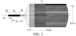
FIG. 3 is another schematic diagram in which tabs of a core of a battery core have not been bent after being converged according to an embodiment of the present invention. - Reference numerals:
-
battery core 10; -
core 20;tab 201;separator 202; tab end-portion staggeredlayer region 203;tab soldering region 204; pre-soldered press-fit region 205;tab exposure region 206;tab protection sheet 207; and -
battery 100. - A detail description of the embodiments of the present invention will be made in the following, and examples thereof are illustrated in the accompanying drawings, throughout which identical or similar elements or elements having identical or similar functions are represented with identical or similar reference numerals. The embodiments that are described with reference to the accompanying drawings are exemplary, and are only used to interpret the present invention, instead limiting the present invention.
- A
battery core 10 according to the embodiments of the present invention is described below with reference toFIG. 1 to FIG. 3 . - As shown in
FIG. 1 to FIG. 3 , thebattery core 10 according to the embodiments of the present invention includes: at least onecore 20, where eachcore 20 has a plurality oftabs 201, the plurality oftabs 201 successively form, after being converged, a tab end-portion staggeredlayer region 203, atab soldering region 204, and a pre-soldered press-fit region 205. It is to be noted that free ends of the plurality oftabs 201 jointly form the tab end-portion staggeredlayer region 203, because curved radians of thetabs 201 are different after the plurality oftabs 201 are converged. The pre-soldered press-fit region 205 is a region formed by press-fitting the plurality oftabs 201, which have been converged, at the position of convergence by ultrasonic soldering or other soldering methods. Thetab soldering region 204 is a region formed by soldering thetabs 201 and a tab lead-out sheet in a laser soldering or another soldering manner in the pre-soldered press-fit region 205. The parts of the plurality oftabs 201 exposed out of thecore 20 form thetab exposure region 206. In an extension direction of thetab 201, that is, a left-right direction shown inFIG. 2 , a length of the tab exposed out of thecore 10 in thetab exposure region 206 is determined according to a width of the tab end-portion staggeredlayer region 203, a width of thetab soldering region 204, a width of the pre-soldered press-fit region 205, a thickness of thecore 20, and a tab bending angle of thetab 201. - A width direction of the tab end-portion staggered
layer region 203, a width direction of thetab soldering region 204, and a width direction of the pre-soldered press-fit region 205 are all the left-right direction shown inFIG. 2 . A thickness direction of thecore 20 is an updown direction shown inFIG. 2 , and when thetabs 201 of thecore 20 have not been bent after being converged, the exposed tab extends in the left-right direction shown inFIG. 2 . Eachcore 20 has a plurality ofseparators 202, and parts of the plurality oftabs 201 exposed out of theseparators 202 form thetab exposure region 206. - By determining the length of the
tab exposure region 206 according to the width of the tab end-portion staggeredlayer region 203, the width of thetab soldering region 204, the width of the pre-soldered press-fit region 205, the thickness of thecore 20, and the tab bending angle of thetab 201, the length of the tab in thetab exposure region 206 exposed out of thecore 20 can be made more appropriate, so as to prevent thetab 201 from being pulled and torn after bending, and avoid the problem that some electrode plates cannot output electricity, thereby avoiding a capacity loss of thebattery core 10. In addition, the movable length of thetab 201 can also be made appropriate, and the bending space for accommodating thetabs 201 can be made appropriate, so as to avoid the capacity loss of thebattery core 10, and prevent thetabs 201 from being compressed to cause positive and negative electrodes of thebattery core 10 to come into contact with each other and cause a short circuit of thebattery core 10, thereby improving the safety of thebattery core 10 in use. - In some embodiments of the present invention, as shown in
FIG. 2 , the width of the tab end-portion staggeredlayer region 203 is d1, thetab soldering region 204 is provided with atab protection sheet 207, a width of thetab protection sheet 207 is d2, a width direction of thetab protection sheet 207 is the left-right direction shown inFIG. 2 , the width of the pre-soldered press-fit region 205 is d3, the thickness of thecore 20 is D, the tab bending angle of any onetab 201 in the plurality oftabs 201 is A, the length of the exposed tab in thetab exposure region 206 is L, and a relational expression L=d1+d2+d3+D/2∗tan A is satisfied. Such a setting can ensure that the length of the tab exposed out of thecore 20 in thetab exposure region 206 is more appropriate, can further prevent thetabs 201 from being pulled after bending, further prevent thetabs 201 from being torn, and avoid the problem that some electrode plates cannot output electricity, thereby further avoiding the capacity loss of thebattery core 10. In addition, the movable length of thetab 201 can be ensured to be more appropriate, and the bending space for accommodating thetabs 201 can be made more appropriate, so as to avoid the capacity loss of thebattery core 10, and further prevent thetabs 201 from being compressed to cause positive and negative electrodes of thebattery core 10 to come into contact with each other, so as to better prevent a short circuit of thebattery core 10, thereby further improving the safety of thebattery 100 in use. - Further, A satisfies a relational expression 45°≤A≤135°, and preferably, 60°≤A≤120°. Such a setting makes the bending angle of the
tab 201 more appropriate, can make the length of the tab exposed out of thecore 20 in thetab exposure region 206 appropriate, and prevent theseparator 202 from being compressed to cause the positive and negative electrode of thebattery core 10 to come into contact with each other, so as to better prevent a short circuit of thebattery core 10. - In some embodiments of the present invention, a ratio of d2 to d1 is B, and satisfies a relational expression 4<B<10. Further, a ratio of d2 to d3 is C, and satisfies a relational expression 4<C<24. Such a setting makes the ratio of d2 to d1 and the ratio of d2 to d3 appropriate, which facilitates the production and manufacture of the
core 20. In addition, the soldering width of thetab soldering region 204 can be made appropriate, so as to ensured that the plurality oftabs 201 can be soldered together reliably, thereby improving the reliability of thebattery core 10 in use. - In some embodiments of the present invention, a relational expression 0 mm<d1<8 mm is satisfied. Preferably, d1 is 4 mm. Such a setting makes the width of the tab end-portion staggered
layer region 203 appropriate, which can prevent the width of the tab end-portion staggeredlayer region 203 from being too large, so as to make the length of thetab exposure region 206 more appropriate. - In some embodiments of the present invention, a relational expression 8 mm≤d2≤12 mm is satisfied. Preferably, d2 is 10 mm. Such a setting makes the width of the
tab protection sheet 207 appropriate, and the soldering width of thetab soldering region 204 can be ensured, so as to make the length of thetab exposure region 206 appropriate, thereby further facilitating the production and manufacture of thecore 20. - In some embodiments of the present invention, a relational expression 0.5 mm≤d3≤2 mm is satisfied. Preferably, d3 is 1.5 mm. When soldering the plurality of
tabs 201, setting d3 to 1.5 mm can make the width of the pre-soldered press-fit region 205 appropriate, so that a pre-soldering and pressing block can firmly press the plurality oftabs 201, so as to ensure the soldering quality of the plurality oftabs 201, thereby ensuring the production quality of thebattery core 10. - A
battery 100 according to the embodiments of the present invention includes thebattery core 10 in the foregoing embodiments, and thebattery core 10 is disposed on thebattery 100. Therefore, the length of the tab exposed out of the core 20 in thetab exposure region 206 can be made more appropriate, and thetab 201 after bending can be prevented from being pulled and torn, so as to avoid a capacity loss of thebattery core 10 and further to avoid the capacity loss of thebattery 100. Moreover, the movable length of thetab 201 can be made appropriate, the bending space can be made appropriate, and therefore, the capacity loss of thebattery core 10 can be avoided. In addition, thetab 201 can be prevented from being compressed, so as to improve the safety of thebattery core 10 in use, and further to improve the safety of thebattery 100 in use. - A battery pack according to the embodiments of the present invention includes the
battery 100 in the foregoing embodiments. Thebattery 100 is disposed in the battery pack, which can avoid the capacity loss of the battery pack and improve the safety of the battery pack in use. - In the description terms such as "an embodiment", "some embodiments", "exemplary embodiments", "example", "specific example", or "some examples" means that specific features, structures, materials or characteristics described with reference to the embodiment or example are included in at least one embodiment or example of the present invention. In this specification, exemplary descriptions of the foregoing terms do not necessarily refer to the same embodiment or example. In addition, the described specific features, structures, materials, or characteristics may be combined in a proper manner in any one or more of the embodiments or examples.
- Although the embodiments of the present invention are already shown and described above, a person of ordinary skill in the art is to be understood that various changes, modifications, replacements, and variations may be made to the embodiments without departing from the principles and spirit of the present invention, and the scope of the present invention is defined by the appended claims and their equivalents.
Claims (10)
- A battery core, comprising:
at least one core, wherein each core has a plurality of tabs, the plurality of tabs successively form, after being converged, a tab end-portion staggered layer region, a tab soldering region, and a pre-soldered press-fit region, parts of the plurality of tabs exposed out of the core form a tab exposure region, and a length of the tab exposed out of the core in the tab exposure region is determined according to a width of the tab end-portion staggered layer region, a width of the tab soldering region, a width of the pre-soldered press-fit region, a thickness of the core, and a tab bending angle of the tab. - The battery core according to claim 1, wherein the width of the tab end-portion staggered layer region is d1, the tab soldering region is provided with a tab protection sheet, a width of the tab protection sheet is d2, the width of the pre-soldered press-fit region is d3, the thickness of the core is D, and the tab bending angle of any one tab in the plurality of tabs is A, the length of the exposed tab in the tab exposure region is L, and a relational expression L=d1+d2+d3+D/2∗tan A is satisfied.
- The battery core according to claim 1, wherein A satisfies a relational expression 45°≤A≤135°.
- The battery core according to claim 2, wherein a ratio of d2 to d1 is B, and satisfies a relational expression 4<B<10.
- The battery core according to claim 2, wherein a ratio of d2 to d3 is C, and satisfies a relational expression 4<C<24.
- The battery core according to claim 2, wherein a relational expression 0 mm<d1<8 mm is satisfied.
- The battery core according to claim 2, wherein a relational expression 8 mm≤d2≤12 mm is satisfied.
- The battery core according to claim 2, wherein a relational expression 0.5 mm≤d3≤2 mm is satisfied.
- A battery, comprising the battery core according to any one of claims 1 to 8.
- A battery pack, comprising the battery according to claim 9.
Applications Claiming Priority (1)
| Application Number | Priority Date | Filing Date | Title |
|---|---|---|---|
| CN202010898785.4A CN114204220B (en) | 2020-08-31 | 2020-08-31 | Battery cell, battery and battery pack |
Publications (1)
| Publication Number | Publication Date |
|---|---|
| EP3961798A1 true EP3961798A1 (en) | 2022-03-02 |
Family
ID=77519062
Family Applications (1)
| Application Number | Title | Priority Date | Filing Date |
|---|---|---|---|
| EP21193350.2A Pending EP3961798A1 (en) | 2020-08-31 | 2021-08-26 | Battery core, battery, and battery pack |
Country Status (6)
| Country | Link |
|---|---|
| US (1) | US20230231287A1 (en) |
| EP (1) | EP3961798A1 (en) |
| JP (1) | JP7576164B2 (en) |
| CN (1) | CN114204220B (en) |
| CA (1) | CA3191039A1 (en) |
| WO (1) | WO2022042493A1 (en) |
Families Citing this family (4)
| Publication number | Priority date | Publication date | Assignee | Title |
|---|---|---|---|---|
| ES2998335T3 (en) * | 2021-10-27 | 2025-02-19 | Contemporary Amperex Technology Hong Kong Ltd | Battery tab detection method and apparatus, and storage medium |
| CN119542694B (en) * | 2023-08-31 | 2025-10-17 | 比亚迪股份有限公司 | Battery monomer, battery device and electric equipment |
| CN119542695B (en) * | 2023-08-31 | 2025-10-17 | 比亚迪股份有限公司 | Battery monomer, battery device and electric equipment |
| WO2025067431A1 (en) * | 2023-09-27 | 2025-04-03 | 湖北亿纬动力有限公司 | Cell pack assembly, battery and battery tab welding method |
Citations (3)
| Publication number | Priority date | Publication date | Assignee | Title |
|---|---|---|---|---|
| US20100028770A1 (en) * | 2006-07-24 | 2010-02-04 | Lg Chem, Ltd | Electrode Assembly Having Electrode Tabs of the Same Size in Joint Portion Thereof and Electrochemical Cell Containing the Same |
| JP2014191967A (en) * | 2013-03-27 | 2014-10-06 | Murata Mfg Co Ltd | Battery |
| KR20180072065A (en) * | 2016-12-21 | 2018-06-29 | 주식회사 엘지화학 | Battery Cell and Manufacturing Method thereof |
Family Cites Families (16)
| Publication number | Priority date | Publication date | Assignee | Title |
|---|---|---|---|---|
| JP3428336B2 (en) * | 1996-12-26 | 2003-07-22 | 松下電器産業株式会社 | Square sealed storage battery |
| JP2002298825A (en) * | 2001-03-29 | 2002-10-11 | Tdk Corp | Method for producing electrochemical device and electrochemical device |
| US9819027B2 (en) * | 2012-06-28 | 2017-11-14 | Toyota Jidosha Kabushiki Kaisha | Method for producing battery and battery |
| JP6045286B2 (en) * | 2012-10-15 | 2016-12-14 | 日立オートモティブシステムズ株式会社 | Cylindrical energy storage device |
| CN104466074B (en) * | 2014-11-24 | 2016-12-07 | 山东精工电子科技有限公司 | A kind of flexible-packed battery pole ear welding method |
| KR102266592B1 (en) * | 2015-03-02 | 2021-06-17 | 삼성에스디아이 주식회사 | Rechargeable battery |
| WO2017077698A1 (en) * | 2015-11-06 | 2017-05-11 | 三洋電機株式会社 | Electrode plate for power storage device and power storage device |
| CN105406107B (en) * | 2015-11-16 | 2019-02-05 | 珠海光宇电池有限公司 | A kind of lithium ion battery and preparation method thereof |
| CN205542998U (en) * | 2015-12-21 | 2016-08-31 | 江西迪比科股份有限公司 | High power wet process cellulose non -woven fabrics diaphragm paper structure aluminum hull lithium ion secondary cell |
| CN106972144B (en) * | 2016-01-14 | 2023-03-17 | 宁德时代新能源科技股份有限公司 | Secondary battery |
| JP6769137B2 (en) * | 2016-06-30 | 2020-10-14 | 株式会社豊田自動織機 | Power storage device |
| JP6930140B2 (en) * | 2017-03-06 | 2021-09-01 | 株式会社村田製作所 | Rechargeable battery |
| KR102145493B1 (en) * | 2017-11-14 | 2020-08-18 | 주식회사 엘지화학 | Electrode assembly, rechargeable battery comprising the same and rechargeable battery manufacturing method |
| CN207781717U (en) * | 2017-12-21 | 2018-08-28 | 河北银隆新能源有限公司 | A kind of lug keaded structure of rectangular cell |
| CN108336286A (en) * | 2018-03-26 | 2018-07-27 | 珠海格力电器股份有限公司 | Large soft package lithium ion battery and preparation method thereof |
| CN210172794U (en) * | 2019-05-30 | 2020-03-24 | 万向一二三股份公司 | A pre-welded baffle device for improving tab foil tearing |
-
2020
- 2020-08-31 CN CN202010898785.4A patent/CN114204220B/en active Active
-
2021
- 2021-08-23 CA CA3191039A patent/CA3191039A1/en active Pending
- 2021-08-23 WO PCT/CN2021/114102 patent/WO2022042493A1/en not_active Ceased
- 2021-08-23 JP JP2023513945A patent/JP7576164B2/en active Active
- 2021-08-26 EP EP21193350.2A patent/EP3961798A1/en active Pending
-
2023
- 2023-02-28 US US18/176,179 patent/US20230231287A1/en active Pending
Patent Citations (3)
| Publication number | Priority date | Publication date | Assignee | Title |
|---|---|---|---|---|
| US20100028770A1 (en) * | 2006-07-24 | 2010-02-04 | Lg Chem, Ltd | Electrode Assembly Having Electrode Tabs of the Same Size in Joint Portion Thereof and Electrochemical Cell Containing the Same |
| JP2014191967A (en) * | 2013-03-27 | 2014-10-06 | Murata Mfg Co Ltd | Battery |
| KR20180072065A (en) * | 2016-12-21 | 2018-06-29 | 주식회사 엘지화학 | Battery Cell and Manufacturing Method thereof |
Also Published As
| Publication number | Publication date |
|---|---|
| CA3191039A1 (en) | 2022-03-03 |
| US20230231287A1 (en) | 2023-07-20 |
| KR20230051239A (en) | 2023-04-17 |
| JP2023539658A (en) | 2023-09-15 |
| CN114204220B (en) | 2023-04-07 |
| JP7576164B2 (en) | 2024-10-30 |
| WO2022042493A1 (en) | 2022-03-03 |
| CN114204220A (en) | 2022-03-18 |
Similar Documents
| Publication | Publication Date | Title |
|---|---|---|
| US20230231287A1 (en) | Battery core, battery, and battery pack | |
| US20230207982A1 (en) | Battery | |
| CN105247726B (en) | The battery pack of the electrode stack of bending and electrode stack including the bending | |
| DE112013003164T5 (en) | accumulator | |
| JP2008027891A (en) | Electrode assembly with same size of electrode tab in joining part and electrochemical cell having this | |
| CN111293277A (en) | Pole piece burr eliminating method, lithium ion battery pole piece and lithium ion battery | |
| KR102373537B1 (en) | Battery module | |
| JPH10270068A (en) | Rectangular battery and its manufacture | |
| WO2017141613A1 (en) | Rectangular secondary battery | |
| EP3961800A1 (en) | Battery and battery pack | |
| JP4686807B2 (en) | Winding battery | |
| CN101662044B (en) | Lithium ion battery and battery pack | |
| CN116235362A (en) | Electrode assembly with coating portion for short circuit prevention | |
| WO2025190372A1 (en) | Full-tab battery jelly roll and sodium-ion battery | |
| CN117878536B (en) | Connector and battery structure | |
| CN219677319U (en) | A three-electrode battery | |
| KR102960346B1 (en) | Cells, batteries, and battery packs | |
| US20220407191A1 (en) | Electrical storage device | |
| CN107978761B (en) | Current collector for an energy storage cell for storing electrical energy | |
| CN114503356A (en) | Secondary battery and method for manufacturing same | |
| CN117059906A (en) | Wound battery | |
| CN218005188U (en) | Naked electric core, lithium cell and vehicle | |
| CN219226366U (en) | Cells and Batteries | |
| US20250219263A1 (en) | Nonaqueous electrolyte battery | |
| CN221530026U (en) | Z-type laminated battery cell |
Legal Events
| Date | Code | Title | Description |
|---|---|---|---|
| PUAI | Public reference made under article 153(3) epc to a published international application that has entered the european phase |
Free format text: ORIGINAL CODE: 0009012 |
|
| STAA | Information on the status of an ep patent application or granted ep patent |
Free format text: STATUS: THE APPLICATION HAS BEEN PUBLISHED |
|
| AK | Designated contracting states |
Kind code of ref document: A1 Designated state(s): AL AT BE BG CH CY CZ DE DK EE ES FI FR GB GR HR HU IE IS IT LI LT LU LV MC MK MT NL NO PL PT RO RS SE SI SK SM TR |
|
| STAA | Information on the status of an ep patent application or granted ep patent |
Free format text: STATUS: REQUEST FOR EXAMINATION WAS MADE |
|
| 17P | Request for examination filed |
Effective date: 20220830 |
|
| RBV | Designated contracting states (corrected) |
Designated state(s): AL AT BE BG CH CY CZ DE DK EE ES FI FR GB GR HR HU IE IS IT LI LT LU LV MC MK MT NL NO PL PT RO RS SE SI SK SM TR |
|
| STAA | Information on the status of an ep patent application or granted ep patent |
Free format text: STATUS: EXAMINATION IS IN PROGRESS |
|
| 17Q | First examination report despatched |
Effective date: 20241129 |