EP3961752A1 - Electrode mounting unit and electrode drying device comprising the same - Google Patents
Electrode mounting unit and electrode drying device comprising the same Download PDFInfo
- Publication number
- EP3961752A1 EP3961752A1 EP21202838.5A EP21202838A EP3961752A1 EP 3961752 A1 EP3961752 A1 EP 3961752A1 EP 21202838 A EP21202838 A EP 21202838A EP 3961752 A1 EP3961752 A1 EP 3961752A1
- Authority
- EP
- European Patent Office
- Prior art keywords
- electrode
- wound around
- roll
- prevention member
- mounting unit
- Prior art date
- Legal status (The legal status is an assumption and is not a legal conclusion. Google has not performed a legal analysis and makes no representation as to the accuracy of the status listed.)
- Granted
Links
Images



Classifications
-
- H—ELECTRICITY
- H01—ELECTRIC ELEMENTS
- H01M—PROCESSES OR MEANS, e.g. BATTERIES, FOR THE DIRECT CONVERSION OF CHEMICAL ENERGY INTO ELECTRICAL ENERGY
- H01M4/00—Electrodes
- H01M4/02—Electrodes composed of, or comprising, active material
- H01M4/04—Processes of manufacture in general
-
- H—ELECTRICITY
- H01—ELECTRIC ELEMENTS
- H01M—PROCESSES OR MEANS, e.g. BATTERIES, FOR THE DIRECT CONVERSION OF CHEMICAL ENERGY INTO ELECTRICAL ENERGY
- H01M4/00—Electrodes
- H01M4/02—Electrodes composed of, or comprising, active material
- H01M4/04—Processes of manufacture in general
- H01M4/0471—Processes of manufacture in general involving thermal treatment, e.g. firing, sintering, backing particulate active material, thermal decomposition, pyrolysis
-
- F—MECHANICAL ENGINEERING; LIGHTING; HEATING; WEAPONS; BLASTING
- F26—DRYING
- F26B—DRYING SOLID MATERIALS OR OBJECTS BY REMOVING LIQUID THEREFROM
- F26B13/00—Machines and apparatus for drying fabrics, fibres, yarns, or other materials in long lengths, with progressive movement
- F26B13/001—Drying and oxidising yarns, ribbons or the like
- F26B13/003—Drying and oxidising yarns, ribbons or the like in the shape of spools, coils, bobbins or the like
-
- F—MECHANICAL ENGINEERING; LIGHTING; HEATING; WEAPONS; BLASTING
- F26—DRYING
- F26B—DRYING SOLID MATERIALS OR OBJECTS BY REMOVING LIQUID THEREFROM
- F26B25/00—Details of general application not covered by group F26B21/00 or F26B23/00
- F26B25/001—Handling, e.g. loading or unloading arrangements
-
- F—MECHANICAL ENGINEERING; LIGHTING; HEATING; WEAPONS; BLASTING
- F26—DRYING
- F26B—DRYING SOLID MATERIALS OR OBJECTS BY REMOVING LIQUID THEREFROM
- F26B25/00—Details of general application not covered by group F26B21/00 or F26B23/00
- F26B25/06—Chambers, containers, or receptacles
- F26B25/14—Chambers, containers, receptacles of simple construction
-
- F—MECHANICAL ENGINEERING; LIGHTING; HEATING; WEAPONS; BLASTING
- F26—DRYING
- F26B—DRYING SOLID MATERIALS OR OBJECTS BY REMOVING LIQUID THEREFROM
- F26B25/00—Details of general application not covered by group F26B21/00 or F26B23/00
- F26B25/06—Chambers, containers, or receptacles
- F26B25/14—Chambers, containers, receptacles of simple construction
- F26B25/18—Chambers, containers, receptacles of simple construction mainly open, e.g. dish, tray, pan, rack
- F26B25/185—Spacers; Elements for supporting the goods to be dried, i.e. positioned in-between the goods to build a ventilated stack
-
- Y—GENERAL TAGGING OF NEW TECHNOLOGICAL DEVELOPMENTS; GENERAL TAGGING OF CROSS-SECTIONAL TECHNOLOGIES SPANNING OVER SEVERAL SECTIONS OF THE IPC; TECHNICAL SUBJECTS COVERED BY FORMER USPC CROSS-REFERENCE ART COLLECTIONS [XRACs] AND DIGESTS
- Y02—TECHNOLOGIES OR APPLICATIONS FOR MITIGATION OR ADAPTATION AGAINST CLIMATE CHANGE
- Y02E—REDUCTION OF GREENHOUSE GAS [GHG] EMISSIONS, RELATED TO ENERGY GENERATION, TRANSMISSION OR DISTRIBUTION
- Y02E60/00—Enabling technologies; Technologies with a potential or indirect contribution to GHG emissions mitigation
- Y02E60/10—Energy storage using batteries
Definitions
- the present invention relates to an electrode mounting unit and an electrode drying device comprising the same, and more particularly, to an electrode mounting unit, which is capable of preventing an electrode wound around an electrode roll from being unwound, and an electrode drying device comprising the same.
- secondary batteries refer to chargeable and dischargeable batteries, unlike primary batteries that are not chargeable.
- the secondary batteries are being widely used in the high-tech electronic fields such as mobile phones, notebook computers, and camcorders.
- Such a secondary battery is classified into a can type secondary battery in which an electrode assembly is built in a metal can and a pouch type secondary battery in which an electrode assembly is built in a pouch.
- the pouch type secondary battery comprises an electrode assembly, an electrolyte, and a pouch accommodating the electrode assembly and the electrolyte.
- the electrode assembly has a structure in which a plurality of electrodes and a plurality of separators are alternately stacked.
- the electrode is wound in a roll shape and then dried through an electrode drying device to remove a residual solvent and residual moisture. That is, the electrode drying device according to the related art dries the electrode wound in the roll shape by using hot air.
- the electrode wound in the roll shape may be easily unwound to be damaged, or process failure may occur by the unwound electrode.
- an object of the present invention is to provide an electrode mounting unit, which comprises an unwinding prevention member for preventing an electrode wound in a roll shape from being unwound to stably mount and dry the electrode, thereby previously preventing process failure from occurring, and an electrode drying device comprising the same.
- an electrode mounting unit comprises: a mounting member comprising a horizontal plate, a vertical plate disposed on a top surface of the horizontal plate, and a shaft which is fixed to the vertical plate and into which an electrode roll is fitted to be mounted; and an unwinding prevention member disposed between the electrode wound around the electrode roll and the horizontal plate to support the electrode wound around the electrode roll so as to prevent the electrode wound around the electrode roll from being unwound.
- a top surface of the unwinding prevention member on which the electrode is supported may be formed as a curved surface having the same curvature radius as the electrode wound around the electrode roll.
- a hook protrusion on which the electrode wound around the electrode roll is hooked and supported may be formed on one end of the curved surface.
- One side surface of the unwinding prevention member may be formed as an inclined surface.
- a handle part may be formed on the other side surface of the unwinding prevention member.
- the unwinding prevention member may be made of a synthetic resin having elastic restoring force.
- An electrode drying device comprises: a mounting unit on which an electrode roll around which an electrode is wound is mounted; and a drying chamber accommodating the mounting unit to dry the electrode wound around the electrode roll, wherein the mounting unit comprises: a mounting member comprising a horizontal plate, a vertical plate disposed on a top surface of the horizontal plate, and a shaft which is fixed to the vertical plate and into which the electrode roll is fitted to be mounted; and an unwinding prevention member disposed between the electrode wound around the electrode roll and the horizontal plate to support the electrode wound around the electrode roll so as to prevent the electrode wound around the electrode roll from being unwound.
- a bottom surface of an unwinding prevention member may be formed as a horizontal surface, wherein an unevenness for preventing sliding may be formed on the horizontal surface.
- an unevenness is formed on a curved surface of an unwinding prevention member.
- the electrode mounting unit of the present invention may comprise the mounting member on which the electrode roll in which the electrode is wound in the roll shape is mounted and the unwinding prevention member supporting the electrode wound around the electrode roll mounted on the mounting member, thereby preventing the electrode wound around the electrode roll from being unwound.
- the top surface of the unwinding prevention member may have the curved surface having the same curvature radius as the electrode wound around the electrode roll.
- the adhesion force between the electrode and the unwinding prevention member may increase to stably support the electrode, thereby significantly preventing the electrode wound around the electrode roll from being unwound.
- the hook protrusion on which one side of the electrode wound around the electrode roll is hooked and supported may be formed on the curved surface of the unwinding prevention member of the prevent invention. Thus, the adhering position between the electrode wound around the electrode roll and the unwinding prevention member may be easily adjusted.
- One side surface of the unwinding prevention member may be formed as the inclined surface.
- the unwinding prevention member may be easily inserted between the electrode wound around the electrode roll and the mounting member. That is, in the case in which the space between the electrode wound around the electrode roll and the mounting member is less than the thickness of the unwinding prevention member, when the inclined surface is closely attached to the bottom surface of the mounting member to tilt the unwinding prevention member, the unwinding prevention member may be easily inserted between the electrode wound around the electrode roll and the mounting member.
- the handle part may be formed on the other side surface of the unwinding prevention member of the present invention.
- the unwinding prevention member may be easily inserted between the electrode wound around the electrode roll and the mounting member or be easily removed.
- the unevenness for preventing the unwinding prevention member from being slid may be formed on the bottom surface of the unwinding prevention member to prevent the unwinding preventing member from moving.
- the electrode wound around the electrode roll may be stably supported and prevented from being unwound.
- the unevenness may be formed on the curved surface of the unwinding prevention member.
- the electrode wound around the electrode roll and the unwinding prevention member may be supported in the multistage to significantly prevent the electrode from being unwound.
- the electrode drying device may comprise the electrode mounting unit and the drying chamber to stably mount and dry the electrode, thereby previously preventing the process failure from occurring.
- an electrode mounting unit 110 comprises a mounting member 111 on which an electrode roll 10, around which an electrode 1 is wound, is mounted and an unwinding prevention member 112 supporting the electrode 1 to prevent the electrode 1 of the electrode roll 10 mounted on the mounting member 111 from being unwound.
- the electrode roll 10 comprises a cylindrical winding part 11 around which the electrode 1 is wound and which has a mounting hole in a center thereof and plate-shaped support parts 12 respectively provided on both ends of the winding part 11 to support both side surfaces of the electrode wound around the winding part 11.
- the winding part 11 and the support parts 12 are integrated with each other.
- the mounting member 111 comprises a horizontal plate 111a, a vertical plate 111b disposed on a top surface of the horizontal plate 111a, and a shaft 111c which is fixed to the vertical plate 111b and into which the electrode roll 10 is fitted to be mounted.
- the horizontal plate 111a and the vertical plate 111b may be connected to each other in a " " shape.
- a space between th horizontal plate 111a and the vertical plate 111b may be effectively used.
- the horizontal plate 111a and the vertical plate 111b may be made of the same material.
- the horizontal plate 111a may have a thickness greater than that of the vertical plate 111b to prevent the vertical plate 111b from falling down through a weight of the horizontal plate 111a.
- the shaft 111c may have a structure that is adjustable in position on the vertical plate 111b in a direction toward or away from the horizontal plate 111a. Thus, an interval between the shaft 111c and the horizontal plate 111a may be adjusted, and thus, the electrode roll 10 having various sizes may be mounted.
- the shaft 111c comprises an insertion part 111c-1 inserted into one side of a long hole 111b-1 formed in the vertical plate 111b in the direction of the horizontal plate 111a and a bolt 111c-3 comprising a support piece 111c-2 disposed on the other side of the long hole 111b-1 and coupled to the insertion part 111c-1 to fix the shaft 111c.
- the bolt 111c-3 may be released or fastened to allow the shaft 111c to ascend or descend within the long hole 111b-1.
- the interval between the shaft 111c and the horizontal plate 111a may be easily adjusted.
- the mounting member 111 having the above-described configuration may comprise the horizontal plate 111a, the vertical plate 111b, and the shaft 111c to easily mount the electrode roll 10 around which the electrode 1 is wound.
- the unwinding prevention member 112 is mounted on the mounting member to prevent the electrode wound around the electrode roll from being unwound.
- the unwinding prevention member 112 is inserted between the electrode 1 wound around the electrode roll 10 and the horizontal plate 111a to support the electrode 1 wound around the electrode roll 10, thereby preventing the electrode 1 wound around the electrode roll 10 from being unwound.
- the electrode 1 wound around the electrode roll 10 may be unwound by restoring force.
- the unwinding prevention member 112 may be press-fitted between the electrode 1 wound around the electrode roll 10 and the horizontal plate 111a to press and support the electrode 1 wound around the electrode roll 10, thereby preventing the electrode 1 wound around the electrode roll 10 from being unwound.
- a top surface of the unwinding prevention member 112 on which the electrode 1 wound around the electrode roll 10 is supported is formed as a curved surface 112a having the same curvature radius as the electrode 1 wound around the electrode roll 10. That is, the top surface of the unwinding prevention member 112 may be formed as the curved surface 112a to increase in adhesion area between the electrode 1 and the curved surface 112a, thereby significantly preventing the electrode 1 wound around the electrode roll 10 from being unwound.
- a hook protrusion 112b is formed on one end 112a-1 of the curved surface 112a so that the electrode wound around the electrode roll 10 is hooked and supported, thereby preventing the electrode 1 wound around the electrode roll 10 from being separated through the one end 112a-1 of the curved surface 112a, and particularly, easily adjusting the adhesion potion between the electrode 1 wound around the electrode roll 10 and the unwinding prevention member 112.
- One side surface of the unwinding prevention member 112 may be formed as an inclined surface 112c, and the unwinding prevention member 112 may be easily inserted between the electrode 1 wound around the electrode roll 10 and the mounting member 111 through the inclined surface 112c. That is, as illustrated in FIG. 5 , when the inclined surface of the unwinding prevention member 112 is closely attached to the mounting member 111, the unwinding prevention member 112 may be easily inserted between the electrode 1 wound around the electrode roll 10 and the mounting member 111.
- the other end 112a-2, on which the inclined surface 112c is disposed may be higher than the other end 112a-1, on which the hook protrusion 112b is disposed, in the direction of the electrode 1. That is, since the hook protrusion 112b is formed, the one end 112a-1 of the curved surface 112a may stably support the electrode 1. However, since the other end 112a-2 of the curved surface 112a does not have the structure that supports the electrode 1, the other end 112a-2 may be formed higher than the one end 112a-1 to prevent the electrode 1 supported on the curved surface 112a from being separated in a direction of the other end 112a-2.
- a height ⁇ from the top surface of the horizontal plate 111 to the other end 112a-2 of the curved surface 112a may be greater than that ⁇ from the top surface of the horizontal plate 111 to the one end 112a-1 of the curved surface 112a.
- a handle part 112d is formed on the other side surface of the unwinding prevention member 112.
- the unwinding prevention member 112 may be tilted through the handle part 112d or may be easily inserted or discharged between the electrode 1 wound around the electrode roll 10 and the mounting member 111 through the handle part 112d.
- the handle part 112d may be integrated with the unwinding prevention member 112 when the unwinding prevention member 112 is formed to improve ease of the manufacture.
- the other side surface of the unwinding prevention member 112 is formed as an inclined surface corresponding to the inclined surface 112c formed on the one side surface of the unwinding prevention member 112, and the handle part 112d is formed on the inclined surface. That is, both side surfaces of the unwinding prevention member 112 may be formed as inclined surfaces having an approximately "V" shape.
- the curved surface 112a formed on the top surface of the unwinding prevention member 112 may be significantly expanded in surface area to more stably support the electrode 1 wound around the electrode roll 10.
- the unwinding prevention member 112 is made of a synthetic resin having elastic restoring force. Particularly, the unwinding prevention member 112 may be made of Viton to elastically support the electrode 1 wound around the electrode roll 10, thereby preventing the electrode 1 from being damaged.
- the Viton may be fluorine rubber and have superior heat resistance, oil resistance, and chemical resistance to significantly prevent the electrode 1 from being damaged.
- the electrode mounting unit 110 having the above-described configuration according to the first embodiment may comprise the mounting member 111 and the unwinding prevention member 112 to stably mount the electrode roll 10 around which the electrode 1 is wound and effectively prevent the electrode 1 wound around the electrode roll 10 from being wound.
- an electrode drying device 100 is configured to dry an electrode wound around an electrode roll and comprises a mounting unit 110 on which the electrode roll 10 around which the electrode 1 is wound is mounted and a drying chamber 120 accommodating the mounting unit 110 to dry the electrode 1 wound around the electrode roll 10.
- the mounting unit 110 comprises a horizontal plate 111, a vertical plate 112 disposed on a top surface of the horizontal plate 111, and a shaft 113 which is fixed to the vertical plate 112 and into which the electrode roll 10 is fitted to be mounted.
- the mounting unit 110 has the same configuration and function as the electrode mounting unit 110 according to the foregoing first embodiment of the present invention, and thus, its detailed description will be omitted.
- the drying chamber 120 has an accommodation space in which the mounting unit 110 is accommodated, and hot air or heat is applied to the electrode roll 10 mounted on the mounting unit 110 to dry the electrode 1 wound around the electrode roll 10.
- the electrode 1 wound around the electrode roll 10 is supported by an unwinding prevention member of the mounting unit 110 to prevent the electrode 1 wound around the electrode roll 10 from being unwound even though the hot air is directly applied to the electrode 1.
- the electrode drying device 100 may prevent the electrode 1 wound around the electrode roll 10 and stably dry the electrode 1 wound around the electrode roll 10.
- a bottom surface of an unwinding prevention member 112 supported on a horizontal plate 111 may be provided as a horizontal surface 112e to stably seat the unwinding prevention member 112 on the horizontal plate 111.
- an unevenness for preventing sliding may be formed on the horizontal surface 112e to prevent the unwinding prevention member 112 from moving on the horizontal plate 111. Therefore, the unwinding prevention member 112 may stably support the electrode 1 wound around the electrode roll 10 to prevent the electrode 1 from being unwound.
- an unevenness may be formed on a curved surface 112a of an unwinding prevention member 112 so that an electrode 1 wound around an electrode roll 10 and the curved surface 112a of the unwinding prevention member 112 may be supported in multistage to significantly prevent the electrode 1 from being unwound, and particularly, to prevent the electrode 1 wound around the electrode roll 10 and supported on the curved surface 112a from slidably moving.
- the unevenness may be formed on the curved surface 112a to form a passage between the electrode 1 and the curved surface 112a, thereby stably drying the electrode 1 disposed on the curved surface 112a.
Landscapes
- Engineering & Computer Science (AREA)
- Mechanical Engineering (AREA)
- General Engineering & Computer Science (AREA)
- Manufacturing & Machinery (AREA)
- Chemical & Material Sciences (AREA)
- Chemical Kinetics & Catalysis (AREA)
- Electrochemistry (AREA)
- General Chemical & Material Sciences (AREA)
- Textile Engineering (AREA)
- Battery Electrode And Active Subsutance (AREA)
- Drying Of Solid Materials (AREA)
- Electric Double-Layer Capacitors Or The Like (AREA)
Abstract
Description
- The present application claims the benefit of the priority of
Korean Patent Application No. 10-2018-0010690, filed on January 29, 2018 - The present invention relates to an electrode mounting unit and an electrode drying device comprising the same, and more particularly, to an electrode mounting unit, which is capable of preventing an electrode wound around an electrode roll from being unwound, and an electrode drying device comprising the same.
- In general, secondary batteries refer to chargeable and dischargeable batteries, unlike primary batteries that are not chargeable. The secondary batteries are being widely used in the high-tech electronic fields such as mobile phones, notebook computers, and camcorders.
- Such a secondary battery is classified into a can type secondary battery in which an electrode assembly is built in a metal can and a pouch type secondary battery in which an electrode assembly is built in a pouch. The pouch type secondary battery comprises an electrode assembly, an electrolyte, and a pouch accommodating the electrode assembly and the electrolyte. Also, the electrode assembly has a structure in which a plurality of electrodes and a plurality of separators are alternately stacked.
- The electrode is wound in a roll shape and then dried through an electrode drying device to remove a residual solvent and residual moisture. That is, the electrode drying device according to the related art dries the electrode wound in the roll shape by using hot air.
- However, when the electrode is dried through the electrode drying device, the electrode wound in the roll shape may be easily unwound to be damaged, or process failure may occur by the unwound electrode.
- The present invention has been made to solve the above problems, an object of the present invention is to provide an electrode mounting unit, which comprises an unwinding prevention member for preventing an electrode wound in a roll shape from being unwound to stably mount and dry the electrode, thereby previously preventing process failure from occurring, and an electrode drying device comprising the same.
- To achieve the above object, an electrode mounting unit according to a first embodiment of the present invention comprises: a mounting member comprising a horizontal plate, a vertical plate disposed on a top surface of the horizontal plate, and a shaft which is fixed to the vertical plate and into which an electrode roll is fitted to be mounted; and an unwinding prevention member disposed between the electrode wound around the electrode roll and the horizontal plate to support the electrode wound around the electrode roll so as to prevent the electrode wound around the electrode roll from being unwound.
- A top surface of the unwinding prevention member on which the electrode is supported may be formed as a curved surface having the same curvature radius as the electrode wound around the electrode roll.
- A hook protrusion on which the electrode wound around the electrode roll is hooked and supported may be formed on one end of the curved surface.
- One side surface of the unwinding prevention member may be formed as an inclined surface.
- A handle part may be formed on the other side surface of the unwinding prevention member.
- The unwinding prevention member may be made of a synthetic resin having elastic restoring force.
- An electrode drying device according to a second embodiment of the present invention comprises: a mounting unit on which an electrode roll around which an electrode is wound is mounted; and a drying chamber accommodating the mounting unit to dry the electrode wound around the electrode roll, wherein the mounting unit comprises: a mounting member comprising a horizontal plate, a vertical plate disposed on a top surface of the horizontal plate, and a shaft which is fixed to the vertical plate and into which the electrode roll is fitted to be mounted; and an unwinding prevention member disposed between the electrode wound around the electrode roll and the horizontal plate to support the electrode wound around the electrode roll so as to prevent the electrode wound around the electrode roll from being unwound.
- In an electrode mounting unit according to a third embodiment of the present invention, a bottom surface of an unwinding prevention member may be formed as a horizontal surface, wherein an unevenness for preventing sliding may be formed on the horizontal surface.
- In an electrode mounting unit according to a fourth embodiment of the present invention, an unevenness is formed on a curved surface of an unwinding prevention member.
- First: The electrode mounting unit of the present invention may comprise the mounting member on which the electrode roll in which the electrode is wound in the roll shape is mounted and the unwinding prevention member supporting the electrode wound around the electrode roll mounted on the mounting member, thereby preventing the electrode wound around the electrode roll from being unwound.
- Second: In the electrode mounting unit of the present invention, the top surface of the unwinding prevention member may have the curved surface having the same curvature radius as the electrode wound around the electrode roll. Thus, the adhesion force between the electrode and the unwinding prevention member may increase to stably support the electrode, thereby significantly preventing the electrode wound around the electrode roll from being unwound.
- Third: The hook protrusion on which one side of the electrode wound around the electrode roll is hooked and supported may be formed on the curved surface of the unwinding prevention member of the prevent invention. Thus, the adhering position between the electrode wound around the electrode roll and the unwinding prevention member may be easily adjusted.
- Fourth: One side surface of the unwinding prevention member may be formed as the inclined surface. Thus, the unwinding prevention member may be easily inserted between the electrode wound around the electrode roll and the mounting member. That is, in the case in which the space between the electrode wound around the electrode roll and the mounting member is less than the thickness of the unwinding prevention member, when the inclined surface is closely attached to the bottom surface of the mounting member to tilt the unwinding prevention member, the unwinding prevention member may be easily inserted between the electrode wound around the electrode roll and the mounting member.
- Fifth: the handle part may be formed on the other side surface of the unwinding prevention member of the present invention. Thus, the unwinding prevention member may be easily inserted between the electrode wound around the electrode roll and the mounting member or be easily removed.
- Sixth: the unevenness for preventing the unwinding prevention member from being slid may be formed on the bottom surface of the unwinding prevention member to prevent the unwinding preventing member from moving. Thus, the electrode wound around the electrode roll may be stably supported and prevented from being unwound.
- Seventh: the unevenness may be formed on the curved surface of the unwinding prevention member. Thus, the electrode wound around the electrode roll and the unwinding prevention member may be supported in the multistage to significantly prevent the electrode from being unwound.
- Eighth: the electrode drying device may comprise the electrode mounting unit and the drying chamber to stably mount and dry the electrode, thereby previously preventing the process failure from occurring.
-
-
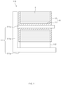
FIG. 1 is a side view of an electrode mounting unit according to a first embodiment of the present invention. -
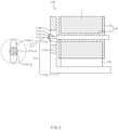
FIG. 2 is a side view illustrating another example of the electrode mounting unit according to the first embodiment of the present invention. -
FIG. 3 is a perspective view illustrating an unwinding prevention member of the electrode mounting unit according to the first embodiment of the present invention. -
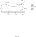
FIG. 4 is a front view of the electrode mounting unit according to the first embodiment of the present invention. -
FIG. 5 is a front view illustrating a state in which the unwinding prevention member of the electrode mounting unit is tilted according to the first embodiment of the present invention. -
FIG. 6 is a side view of an electrode drying device according to a second embodiment of the present invention. -
FIG. 7 is a front view of an electrode drying device according to a third embodiment of the present invention. -
FIG. 8 is a front view of an electrode drying device according to a fourth embodiment of the present invention. - Hereinafter, embodiments of the present invention will be described in detail with reference to the accompanying drawings in such a manner that the technical idea of the present invention may easily be carried out by a person with ordinary skill in the art to which the invention pertains. The present invention may, however, be embodied in different forms and should not be construed as limited to the embodiments set forth herein. In the drawings, anything unnecessary for describing the present invention will be omitted for clarity, and also like reference numerals in the drawings denote like elements.
- As illustrated in
FIG. 1 , anelectrode mounting unit 110 according to a first embodiment of the present invention comprises amounting member 111 on which anelectrode roll 10, around which anelectrode 1 is wound, is mounted and anunwinding prevention member 112 supporting theelectrode 1 to prevent theelectrode 1 of theelectrode roll 10 mounted on themounting member 111 from being unwound. - The
electrode roll 10 comprises acylindrical winding part 11 around which theelectrode 1 is wound and which has a mounting hole in a center thereof and plate-shaped support parts 12 respectively provided on both ends of thewinding part 11 to support both side surfaces of the electrode wound around thewinding part 11. Thewinding part 11 and thesupport parts 12 are integrated with each other. - The
mounting member 111 comprises ahorizontal plate 111a, avertical plate 111b disposed on a top surface of thehorizontal plate 111a, and ashaft 111c which is fixed to thevertical plate 111b and into which theelectrode roll 10 is fitted to be mounted. - Here, the
horizontal plate 111a and thevertical plate 111b may be connected to each other in a "" shape. Thus, a space between th
horizontal plate 111a and thevertical plate 111b may be effectively used. - Particularly, the
horizontal plate 111a and thevertical plate 111b may be made of the same material. Thehorizontal plate 111a may have a thickness greater than that of thevertical plate 111b to prevent thevertical plate 111b from falling down through a weight of thehorizontal plate 111a. - Also, the
shaft 111c may have a structure that is adjustable in position on thevertical plate 111b in a direction toward or away from thehorizontal plate 111a. Thus, an interval between theshaft 111c and thehorizontal plate 111a may be adjusted, and thus, theelectrode roll 10 having various sizes may be mounted. - For example, as illustrated in
FIG. 2 , theshaft 111c comprises aninsertion part 111c-1 inserted into one side of along hole 111b-1 formed in thevertical plate 111b in the direction of thehorizontal plate 111a and abolt 111c-3 comprising asupport piece 111c-2 disposed on the other side of thelong hole 111b-1 and coupled to theinsertion part 111c-1 to fix theshaft 111c. - That is, the
bolt 111c-3 may be released or fastened to allow theshaft 111c to ascend or descend within thelong hole 111b-1. Thus, the interval between theshaft 111c and thehorizontal plate 111a may be easily adjusted. - The mounting
member 111 having the above-described configuration may comprise thehorizontal plate 111a, thevertical plate 111b, and theshaft 111c to easily mount theelectrode roll 10 around which theelectrode 1 is wound. - As illustrated in
FIGS. 3 and4 , the unwindingprevention member 112 is mounted on the mounting member to prevent the electrode wound around the electrode roll from being unwound. The unwindingprevention member 112 is inserted between theelectrode 1 wound around theelectrode roll 10 and thehorizontal plate 111a to support theelectrode 1 wound around theelectrode roll 10, thereby preventing theelectrode 1 wound around theelectrode roll 10 from being unwound. - That is, the
electrode 1 wound around theelectrode roll 10 may be unwound by restoring force. Here, the unwindingprevention member 112 may be press-fitted between theelectrode 1 wound around theelectrode roll 10 and thehorizontal plate 111a to press and support theelectrode 1 wound around theelectrode roll 10, thereby preventing theelectrode 1 wound around theelectrode roll 10 from being unwound. - Particularly, a top surface of the unwinding
prevention member 112 on which theelectrode 1 wound around theelectrode roll 10 is supported is formed as acurved surface 112a having the same curvature radius as theelectrode 1 wound around theelectrode roll 10. That is, the top surface of the unwindingprevention member 112 may be formed as thecurved surface 112a to increase in adhesion area between theelectrode 1 and thecurved surface 112a, thereby significantly preventing theelectrode 1 wound around theelectrode roll 10 from being unwound. - A
hook protrusion 112b is formed on oneend 112a-1 of thecurved surface 112a so that the electrode wound around theelectrode roll 10 is hooked and supported, thereby preventing theelectrode 1 wound around theelectrode roll 10 from being separated through the oneend 112a-1 of thecurved surface 112a, and particularly, easily adjusting the adhesion potion between theelectrode 1 wound around theelectrode roll 10 and the unwindingprevention member 112. - One side surface of the unwinding
prevention member 112 may be formed as aninclined surface 112c, and the unwindingprevention member 112 may be easily inserted between theelectrode 1 wound around theelectrode roll 10 and the mountingmember 111 through theinclined surface 112c. That is, as illustrated inFIG. 5 , when the inclined surface of the unwindingprevention member 112 is closely attached to the mountingmember 111, the unwindingprevention member 112 may be easily inserted between theelectrode 1 wound around theelectrode roll 10 and the mountingmember 111. - As illustrated in
FIG. 4 , in thecurved surface 112a, theother end 112a-2, on which theinclined surface 112c is disposed, may be higher than theother end 112a-1, on which thehook protrusion 112b is disposed, in the direction of theelectrode 1. That is, since thehook protrusion 112b is formed, the oneend 112a-1 of thecurved surface 112a may stably support theelectrode 1. However, since theother end 112a-2 of thecurved surface 112a does not have the structure that supports theelectrode 1, theother end 112a-2 may be formed higher than the oneend 112a-1 to prevent theelectrode 1 supported on thecurved surface 112a from being separated in a direction of theother end 112a-2. - In more detail, referring to
FIG. 4 , a height α from the top surface of thehorizontal plate 111 to theother end 112a-2 of thecurved surface 112a may be greater than that β from the top surface of thehorizontal plate 111 to the oneend 112a-1 of thecurved surface 112a. - A
handle part 112d is formed on the other side surface of the unwindingprevention member 112. The unwindingprevention member 112 may be tilted through thehandle part 112d or may be easily inserted or discharged between theelectrode 1 wound around theelectrode roll 10 and the mountingmember 111 through thehandle part 112d. Also, thehandle part 112d may be integrated with the unwindingprevention member 112 when the unwindingprevention member 112 is formed to improve ease of the manufacture. - Particularly, the other side surface of the unwinding
prevention member 112 is formed as an inclined surface corresponding to theinclined surface 112c formed on the one side surface of the unwindingprevention member 112, and thehandle part 112d is formed on the inclined surface. That is, both side surfaces of the unwindingprevention member 112 may be formed as inclined surfaces having an approximately "V" shape. Thus, thecurved surface 112a formed on the top surface of the unwindingprevention member 112 may be significantly expanded in surface area to more stably support theelectrode 1 wound around theelectrode roll 10. - The unwinding
prevention member 112 is made of a synthetic resin having elastic restoring force. Particularly, the unwindingprevention member 112 may be made of Viton to elastically support theelectrode 1 wound around theelectrode roll 10, thereby preventing theelectrode 1 from being damaged. The Viton may be fluorine rubber and have superior heat resistance, oil resistance, and chemical resistance to significantly prevent theelectrode 1 from being damaged. - Thus, the
electrode mounting unit 110 having the above-described configuration according to the first embodiment may comprise the mountingmember 111 and the unwindingprevention member 112 to stably mount theelectrode roll 10 around which theelectrode 1 is wound and effectively prevent theelectrode 1 wound around theelectrode roll 10 from being wound. - Hereinafter, in descriptions of another embodiment of the present invention, constituents having the same configuration and function as the abovementioned embodiment have been given the same reference numeral in the drawings, and thus duplicated description will be omitted.
- As illustrated in
FIG. 6 , anelectrode drying device 100 according to a second embodiment of the present invention is configured to dry an electrode wound around an electrode roll and comprises a mountingunit 110 on which theelectrode roll 10 around which theelectrode 1 is wound is mounted and a dryingchamber 120 accommodating the mountingunit 110 to dry theelectrode 1 wound around theelectrode roll 10. - The mounting
unit 110 comprises ahorizontal plate 111, avertical plate 112 disposed on a top surface of thehorizontal plate 111, and a shaft 113 which is fixed to thevertical plate 112 and into which theelectrode roll 10 is fitted to be mounted. - Here, the mounting
unit 110 has the same configuration and function as theelectrode mounting unit 110 according to the foregoing first embodiment of the present invention, and thus, its detailed description will be omitted. - The drying
chamber 120 has an accommodation space in which the mountingunit 110 is accommodated, and hot air or heat is applied to theelectrode roll 10 mounted on the mountingunit 110 to dry theelectrode 1 wound around theelectrode roll 10. - Here, the
electrode 1 wound around theelectrode roll 10 is supported by an unwinding prevention member of the mountingunit 110 to prevent theelectrode 1 wound around theelectrode roll 10 from being unwound even though the hot air is directly applied to theelectrode 1. - Thus, the
electrode drying device 100 according to the second embodiment of the present invention may prevent theelectrode 1 wound around theelectrode roll 10 and stably dry theelectrode 1 wound around theelectrode roll 10. - In an electrode mounting unit according to a third embodiment of the present invention, as illustrated in
FIG. 7 , a bottom surface of anunwinding prevention member 112 supported on ahorizontal plate 111 may be provided as ahorizontal surface 112e to stably seat the unwindingprevention member 112 on thehorizontal plate 111. - Particularly, an unevenness for preventing sliding may be formed on the
horizontal surface 112e to prevent theunwinding prevention member 112 from moving on thehorizontal plate 111. Therefore, the unwindingprevention member 112 may stably support theelectrode 1 wound around theelectrode roll 10 to prevent theelectrode 1 from being unwound. - In an
electrode mounting unit 110 according to a fourth embodiment of the present invention, as illustrated inFIG. 8 , an unevenness may be formed on acurved surface 112a of anunwinding prevention member 112 so that anelectrode 1 wound around anelectrode roll 10 and thecurved surface 112a of the unwindingprevention member 112 may be supported in multistage to significantly prevent theelectrode 1 from being unwound, and particularly, to prevent theelectrode 1 wound around theelectrode roll 10 and supported on thecurved surface 112a from slidably moving. Particularly, the unevenness may be formed on thecurved surface 112a to form a passage between theelectrode 1 and thecurved surface 112a, thereby stably drying theelectrode 1 disposed on thecurved surface 112a. - Accordingly, the scope of the present invention is defined by the appended claims rather than the foregoing description and the exemplary embodiments described therein. Various modifications made within the meaning of an equivalent of the claims of the invention and within the claims are to be regarded to be in the scope of the present invention.
-
-
Item 1. An electrode mounting unit comprising:- a mounting member comprising a horizontal plate, a vertical plate disposed on a top surface of the horizontal plate, and a shaft which is fixed to the vertical plate and into which an electrode roll is fitted to be mounted; and
- an unwinding prevention member disposed between the electrode wound around the electrode roll and the horizontal plate to support the electrode wound around the electrode roll so as to prevent the electrode wound around the electrode roll from being unwound.
-
Item 2. The electrode mounting unit ofitem 1, wherein a top surface of the unwinding prevention member on which the electrode is supported is formed as a curved surface having the same curvature radius as the electrode wound around the electrode roll. -
Item 3. The electrode mounting unit ofitem 2, wherein a hook protrusion on which the electrode wound around the electrode roll is hooked and supported is formed on one end of the curved surface. - Item 4. The electrode mounting unit of
item 1, wherein one side surface of the unwinding prevention member is formed as an inclined surface. - Item 5. The electrode mounting unit of item 4, wherein a handle part is formed on the other side surface of the unwinding prevention member.
- Item 6. The electrode mounting unit of
item 1, wherein a bottom surface of the unwinding prevention member is formed as a horizontal surface,
wherein an unevenness for preventing sliding is formed on the horizontal surface. - Item 7. The electrode mounting unit of
item 1, wherein the unwinding prevention member is made of a synthetic resin having elastic restoring force. - Item 8. The electrode mounting unit of
item 2, wherein an unevenness is formed on the curved surface. - Item 9. An electrode drying device comprising:
- a mounting unit on which an electrode roll around which an electrode is wound is mounted; and
- a drying chamber accommodating the mounting unit to dry the electrode wound around the electrode roll,
- wherein the mounting unit comprises:
- a mounting member comprising a horizontal plate, a vertical plate disposed on a top surface of the horizontal plate, and a shaft which is fixed to the vertical plate and into which the electrode roll is fitted to be mounted; and
- an unwinding prevention member disposed between the electrode wound around the electrode roll and the horizontal plate to support the electrode wound around the electrode roll so as to prevent the electrode wound around the electrode roll from being unwound.
-
Item 10. The electrode drying device of item 9, wherein a top surface of the unwinding prevention member on which the electrode is supported is formed as a curved surface having the same curvature radius as the electrode wound around the electrode roll.
Claims (7)
- An electrode mounting unit (110) comprising:a mounting member (111) comprising a horizontal plate (111a), a vertical plate (111b) disposed on a top surface of the horizontal plate (111a), and a shaft (111c) which is fixed to the vertical plate (111b) and into which an electrode roll (10) is fitted to be mounted; andan unwinding prevention member (112) press-fitted between the electrode (1) wound around the electrode roll (10) and the horizontal plate (111a) to press and support the electrode (1) wound around the electrode roll (10) so as to prevent the electrode (1) wound around the electrode roll (10) from being unwound,wherein a top surface of the unwinding prevention member (112) on which the electrode (1) is supported is formed as a curved surface (112a) having the same curvature radius as the electrode (1) wound around the electrode roll (10),wherein a hook protrusion (112b) on which the electrode (1) wound around the electrode roll (10) is hooked and supported is formed on one end (112a-1) of the curved surface (112a).
- The electrode mounting unit (110) of claim 1, wherein one side surface of the unwinding prevention member (112) is formed as an inclined surface (112c).
- The electrode mounting unit (110) of claim 2, wherein a handle part (112d) is formed on the other side surface of the unwinding prevention member (112) for easily inserting it between the electrode (1) wound around the electrode roll (10) and the mounting member (111) and easily removing it.
- The electrode mounting unit of claim 1, wherein a bottom surface of the unwinding prevention member is formed as a horizontal surface,
wherein an unevenness for preventing sliding is formed on the horizontal surface. - The electrode mounting unit (110) of claim 1, wherein the unwinding prevention member (112) is made of a synthetic resin having elastic restoring force.
- The electrode mounting unit (110) of claim 1, wherein an unevenness is formed on the curved surface (112a).
- An electrode drying device (100) comprising:a mounting unit (110) on which an electrode roll (10) around which an electrode (1) is wound is mounted; anda drying chamber (120) accommodating the mounting unit (110) to dry the electrode (1) wound around the electrode roll (10), wherein the mounting unit (110) comprises:a mounting member (111) comprising a horizontal plate (111a), a vertical plate (111b) disposed on a top surface of the horizontal plate (111a), and a shaft (111c) which is fixed to the vertical plate (111b) and into which the electrode roll (10) is fitted to be mounted; andan unwinding prevention member (112) press-fitted between the electrode (1) wound around the electrode roll (10) and the horizontal plate (111a) to press and support the electrode (1) wound around the electrode roll (10) so as to prevent the electrode (1) wound around the electrode roll (10) from being unwound,wherein a top surface of the unwinding prevention member (112) on which the electrode (1) is supported is formed as a curved surface (112a) having the same curvature radius as the electrode (1) wound around the electrode roll (10),wherein a hook protrusion (112b) on which the electrode (1) wound around the electrode roll (10) is hooked and supported is formed on one end (112a-1) of the curved surface (112a).
Applications Claiming Priority (3)
| Application Number | Priority Date | Filing Date | Title |
|---|---|---|---|
| KR1020180010690A KR102277733B1 (en) | 2018-01-29 | 2018-01-29 | Electrode mounting unit and electrode drying device including the same |
| PCT/KR2018/016587 WO2019146919A1 (en) | 2018-01-29 | 2018-12-24 | Electrode mounting unit and electrode drying device including same |
| EP18902671.9A EP3591745B1 (en) | 2018-01-29 | 2018-12-24 | Electrode mounting unit and electrode drying device comprising the same |
Related Parent Applications (2)
| Application Number | Title | Priority Date | Filing Date |
|---|---|---|---|
| EP18902671.9A Division EP3591745B1 (en) | 2018-01-29 | 2018-12-24 | Electrode mounting unit and electrode drying device comprising the same |
| EP18902671.9A Division-Into EP3591745B1 (en) | 2018-01-29 | 2018-12-24 | Electrode mounting unit and electrode drying device comprising the same |
Publications (2)
| Publication Number | Publication Date |
|---|---|
| EP3961752A1 true EP3961752A1 (en) | 2022-03-02 |
| EP3961752B1 EP3961752B1 (en) | 2023-06-07 |
Family
ID=67394978
Family Applications (2)
| Application Number | Title | Priority Date | Filing Date |
|---|---|---|---|
| EP18902671.9A Active EP3591745B1 (en) | 2018-01-29 | 2018-12-24 | Electrode mounting unit and electrode drying device comprising the same |
| EP21202838.5A Active EP3961752B1 (en) | 2018-01-29 | 2018-12-24 | Electrode mounting unit and electrode drying device comprising the same |
Family Applications Before (1)
| Application Number | Title | Priority Date | Filing Date |
|---|---|---|---|
| EP18902671.9A Active EP3591745B1 (en) | 2018-01-29 | 2018-12-24 | Electrode mounting unit and electrode drying device comprising the same |
Country Status (6)
| Country | Link |
|---|---|
| US (1) | US11041675B2 (en) |
| EP (2) | EP3591745B1 (en) |
| KR (1) | KR102277733B1 (en) |
| CN (2) | CN115275086B (en) |
| PL (1) | PL3591745T3 (en) |
| WO (1) | WO2019146919A1 (en) |
Families Citing this family (2)
| Publication number | Priority date | Publication date | Assignee | Title |
|---|---|---|---|---|
| KR102277733B1 (en) * | 2018-01-29 | 2021-07-16 | 주식회사 엘지에너지솔루션 | Electrode mounting unit and electrode drying device including the same |
| CN116914068B (en) * | 2023-09-06 | 2023-11-24 | 常州纳科诺尔精密轧制设备有限公司 | Pole piece hot rolling mechanism and using method thereof |
Citations (5)
| Publication number | Priority date | Publication date | Assignee | Title |
|---|---|---|---|---|
| EP0827222A2 (en) * | 1996-08-28 | 1998-03-04 | Dai Nippon Printing Co., Ltd. | Packaged electrode plate for secondary battery with nonaqueous electrolyte |
| US20040163984A1 (en) * | 2002-11-29 | 2004-08-26 | Daido Metal Company Ltd. | Container suitable for use in transportation of rolls |
| US20130288115A1 (en) * | 2012-04-26 | 2013-10-31 | Medtronic, Inc. | Mandrel for electrode assemblies |
| WO2017086592A1 (en) * | 2015-11-20 | 2017-05-26 | 주식회사 엘지화학 | Electrode drying device, and battery cell comprising electrode manufactured according to same |
| CN107200180A (en) * | 2017-05-27 | 2017-09-26 | 力神电池(苏州)有限公司 | A kind of turnover device of novel battery pole piece |
Family Cites Families (24)
| Publication number | Priority date | Publication date | Assignee | Title |
|---|---|---|---|---|
| JPH07282804A (en) * | 1994-04-14 | 1995-10-27 | Mitsui Mining & Smelting Co Ltd | Reel winding method for thick lithium metal or lithium alloy tape |
| KR0153364B1 (en) | 1995-11-17 | 1998-11-16 | 배순훈 | Lithium Battery with Heat Dissipation Net |
| JP2002280078A (en) | 2001-03-16 | 2002-09-27 | Sony Corp | Battery |
| CN1426950A (en) * | 2001-12-12 | 2003-07-02 | 山代常一朗 | Film Roll Holder |
| JP4241289B2 (en) | 2003-08-01 | 2009-03-18 | 大日本印刷株式会社 | Package of electrode plate tape roll |
| KR200375048Y1 (en) * | 2004-09-17 | 2005-02-05 | 전도영 | anti-unlacing device for bobbin |
| TWM271864U (en) * | 2005-02-01 | 2005-08-01 | Yang Bey Ind Co Ltd | Tape rolls clipping device of tape dispenser |
| KR20080108721A (en) | 2007-06-11 | 2008-12-16 | 주식회사 엘지화학 | Cylindrical secondary battery having a shorter electrolyte injection time |
| JP4775668B2 (en) * | 2008-08-28 | 2011-09-21 | トヨタ自動車株式会社 | Method and apparatus for manufacturing wound electrode body, and method for manufacturing battery |
| KR101333395B1 (en) * | 2009-03-30 | 2013-11-28 | 도요타지도샤가부시키가이샤 | Coating die and coating apparatus comprising the same |
| KR101141216B1 (en) | 2010-01-18 | 2012-07-12 | 이계설 | Apparatus and method for winding Electrode assembly |
| JP4888575B2 (en) | 2010-02-17 | 2012-02-29 | 日産自動車株式会社 | Drying apparatus and drying method |
| CN102683634B (en) | 2012-04-24 | 2014-08-06 | 张贵萍 | High-capacity cylindrical lithium ion cell and production method thereof |
| KR101925583B1 (en) * | 2012-11-06 | 2018-12-05 | 삼성에스디아이 주식회사 | Winding appratus for elctrode of rechargeable battery and winding method using thereof |
| JP6131178B2 (en) * | 2013-01-18 | 2017-05-17 | 東京エレクトロン株式会社 | Roll-shaped container, substrate processing system, substrate processing method, program, and computer storage medium |
| US9991498B2 (en) * | 2013-09-09 | 2018-06-05 | Samsung Electronics Co., Ltd. | Electrode assembly and secondary battery including the same |
| KR20150037407A (en) * | 2013-09-30 | 2015-04-08 | 주식회사 엘지화학 | Secondary battery and method for manufacturing the same |
| NL1040595C2 (en) * | 2014-01-08 | 2015-07-09 | Techniek In Tuinbouw B V | SYSTEM FOR ROLLING UP AND ROLLING OUT FLOOR COVERS. |
| KR101563353B1 (en) | 2014-03-25 | 2015-10-26 | 김탁 | Cable bag |
| KR101710895B1 (en) * | 2015-06-08 | 2017-03-02 | 전남대학교산학협력단 | Cable holder to prevent loosening of the cable and winch including thereof |
| KR101936339B1 (en) * | 2015-08-31 | 2019-04-03 | 주식회사 엘지화학 | Device for Manufacturing Electrode for Secondary Battery Comprising Mold for Providing Electrode Mix Layer |
| CN106766787B (en) * | 2017-03-01 | 2023-07-11 | 深圳市新伟创实业有限公司 | Pole piece hot roller drying system |
| CN107123786A (en) * | 2017-06-16 | 2017-09-01 | 广东亿鑫丰智能装备股份有限公司 | A kind of air-flotation type roll forming machine |
| KR102277733B1 (en) * | 2018-01-29 | 2021-07-16 | 주식회사 엘지에너지솔루션 | Electrode mounting unit and electrode drying device including the same |
-
2018
- 2018-01-29 KR KR1020180010690A patent/KR102277733B1/en active Active
- 2018-12-24 PL PL18902671T patent/PL3591745T3/en unknown
- 2018-12-24 EP EP18902671.9A patent/EP3591745B1/en active Active
- 2018-12-24 WO PCT/KR2018/016587 patent/WO2019146919A1/en not_active Ceased
- 2018-12-24 CN CN202210714063.8A patent/CN115275086B/en active Active
- 2018-12-24 US US16/603,930 patent/US11041675B2/en active Active
- 2018-12-24 EP EP21202838.5A patent/EP3961752B1/en active Active
- 2018-12-24 CN CN201880024100.4A patent/CN110495020B/en active Active
Patent Citations (5)
| Publication number | Priority date | Publication date | Assignee | Title |
|---|---|---|---|---|
| EP0827222A2 (en) * | 1996-08-28 | 1998-03-04 | Dai Nippon Printing Co., Ltd. | Packaged electrode plate for secondary battery with nonaqueous electrolyte |
| US20040163984A1 (en) * | 2002-11-29 | 2004-08-26 | Daido Metal Company Ltd. | Container suitable for use in transportation of rolls |
| US20130288115A1 (en) * | 2012-04-26 | 2013-10-31 | Medtronic, Inc. | Mandrel for electrode assemblies |
| WO2017086592A1 (en) * | 2015-11-20 | 2017-05-26 | 주식회사 엘지화학 | Electrode drying device, and battery cell comprising electrode manufactured according to same |
| CN107200180A (en) * | 2017-05-27 | 2017-09-26 | 力神电池(苏州)有限公司 | A kind of turnover device of novel battery pole piece |
Also Published As
| Publication number | Publication date |
|---|---|
| EP3591745A1 (en) | 2020-01-08 |
| PL3591745T3 (en) | 2022-02-14 |
| WO2019146919A1 (en) | 2019-08-01 |
| US11041675B2 (en) | 2021-06-22 |
| CN115275086A (en) | 2022-11-01 |
| CN110495020B (en) | 2022-07-12 |
| CN115275086B (en) | 2026-03-03 |
| KR20190091744A (en) | 2019-08-07 |
| CN110495020A (en) | 2019-11-22 |
| EP3591745B1 (en) | 2021-12-01 |
| EP3961752B1 (en) | 2023-06-07 |
| US20200124349A1 (en) | 2020-04-23 |
| KR102277733B1 (en) | 2021-07-16 |
| EP3591745A4 (en) | 2020-07-01 |
Similar Documents
| Publication | Publication Date | Title |
|---|---|---|
| TWI682572B (en) | Clamping member and battery module using the same | |
| EP3961752B1 (en) | Electrode mounting unit and electrode drying device comprising the same | |
| US20210171218A1 (en) | Docking station for unmanned aerial vehicles | |
| US6376126B1 (en) | Composite battery container with integral flexible ribs | |
| US7867645B2 (en) | Latching mechanism for battery cover assembly | |
| US9553295B2 (en) | Battery pack | |
| US20170133641A1 (en) | Battery rack | |
| US9806301B2 (en) | Battery pack | |
| US20070133151A1 (en) | Battery module | |
| CN110206979B (en) | Clamping device | |
| WO2016076578A1 (en) | Pressing jig for secondary battery cell | |
| JP2002535693A (en) | Optical component holding box | |
| CN115298112B (en) | Internal tray for transferring battery cells and tray for transferring battery cells including the same | |
| US6981594B1 (en) | Method and apparatus to facilitate transport of semiconductor wafers | |
| US7043130B2 (en) | Fiber management apparatus | |
| WO2025074393A1 (en) | Cell grip mechanism through crush rib | |
| CN119208926A (en) | Battery Pack | |
| KR101073870B1 (en) | Secondary battery case manufacturing method | |
| KR101881568B1 (en) | Hanger for test-tube | |
| US20070068884A1 (en) | Napkin holder assembly | |
| CN212878857U (en) | Foldable storage rack | |
| CN111987770B (en) | Charging box | |
| US20230268598A1 (en) | Tray for Secondary Battery and Tray Assembly Comprising the Same | |
| CN119011712A (en) | Supporting device | |
| CN212830646U (en) | Foldable garbage can |
Legal Events
| Date | Code | Title | Description |
|---|---|---|---|
| PUAI | Public reference made under article 153(3) epc to a published international application that has entered the european phase |
Free format text: ORIGINAL CODE: 0009012 |
|
| STAA | Information on the status of an ep patent application or granted ep patent |
Free format text: STATUS: REQUEST FOR EXAMINATION WAS MADE |
|
| 17P | Request for examination filed |
Effective date: 20211015 |
|
| AC | Divisional application: reference to earlier application |
Ref document number: 3591745 Country of ref document: EP Kind code of ref document: P |
|
| AK | Designated contracting states |
Kind code of ref document: A1 Designated state(s): AL AT BE BG CH CY CZ DE DK EE ES FI FR GB GR HR HU IE IS IT LI LT LU LV MC MK MT NL NO PL PT RO RS SE SI SK SM TR |
|
| RAP1 | Party data changed (applicant data changed or rights of an application transferred) |
Owner name: LG ENERGY SOLUTION, LTD. |
|
| RIC1 | Information provided on ipc code assigned before grant |
Ipc: F26B 25/18 20060101ALI20221130BHEP Ipc: F26B 13/00 20060101ALI20221130BHEP Ipc: B65D 81/00 20060101ALI20221130BHEP Ipc: F26B 25/14 20060101ALI20221130BHEP Ipc: H01M 4/04 20060101AFI20221130BHEP |
|
| GRAP | Despatch of communication of intention to grant a patent |
Free format text: ORIGINAL CODE: EPIDOSNIGR1 |
|
| STAA | Information on the status of an ep patent application or granted ep patent |
Free format text: STATUS: GRANT OF PATENT IS INTENDED |
|
| INTG | Intention to grant announced |
Effective date: 20230109 |
|
| GRAS | Grant fee paid |
Free format text: ORIGINAL CODE: EPIDOSNIGR3 |
|
| GRAA | (expected) grant |
Free format text: ORIGINAL CODE: 0009210 |
|
| STAA | Information on the status of an ep patent application or granted ep patent |
Free format text: STATUS: THE PATENT HAS BEEN GRANTED |
|
| AC | Divisional application: reference to earlier application |
Ref document number: 3591745 Country of ref document: EP Kind code of ref document: P |
|
| AK | Designated contracting states |
Kind code of ref document: B1 Designated state(s): AL AT BE BG CH CY CZ DE DK EE ES FI FR GB GR HR HU IE IS IT LI LT LU LV MC MK MT NL NO PL PT RO RS SE SI SK SM TR |
|
| REG | Reference to a national code |
Ref country code: GB Ref legal event code: FG4D |
|
| REG | Reference to a national code |
Ref country code: CH Ref legal event code: EP Ref country code: AT Ref legal event code: REF Ref document number: 1577601 Country of ref document: AT Kind code of ref document: T Effective date: 20230615 |
|
| REG | Reference to a national code |
Ref country code: DE Ref legal event code: R096 Ref document number: 602018051749 Country of ref document: DE |
|
| P01 | Opt-out of the competence of the unified patent court (upc) registered |
Effective date: 20230525 |
|
| REG | Reference to a national code |
Ref country code: LT Ref legal event code: MG9D |
|
| REG | Reference to a national code |
Ref country code: NL Ref legal event code: MP Effective date: 20230607 |
|
| PG25 | Lapsed in a contracting state [announced via postgrant information from national office to epo] |
Ref country code: SE Free format text: LAPSE BECAUSE OF FAILURE TO SUBMIT A TRANSLATION OF THE DESCRIPTION OR TO PAY THE FEE WITHIN THE PRESCRIBED TIME-LIMIT Effective date: 20230607 Ref country code: NO Free format text: LAPSE BECAUSE OF FAILURE TO SUBMIT A TRANSLATION OF THE DESCRIPTION OR TO PAY THE FEE WITHIN THE PRESCRIBED TIME-LIMIT Effective date: 20230907 Ref country code: ES Free format text: LAPSE BECAUSE OF FAILURE TO SUBMIT A TRANSLATION OF THE DESCRIPTION OR TO PAY THE FEE WITHIN THE PRESCRIBED TIME-LIMIT Effective date: 20230607 |
|
| REG | Reference to a national code |
Ref country code: AT Ref legal event code: MK05 Ref document number: 1577601 Country of ref document: AT Kind code of ref document: T Effective date: 20230607 |
|
| PG25 | Lapsed in a contracting state [announced via postgrant information from national office to epo] |
Ref country code: RS Free format text: LAPSE BECAUSE OF FAILURE TO SUBMIT A TRANSLATION OF THE DESCRIPTION OR TO PAY THE FEE WITHIN THE PRESCRIBED TIME-LIMIT Effective date: 20230607 Ref country code: NL Free format text: LAPSE BECAUSE OF FAILURE TO SUBMIT A TRANSLATION OF THE DESCRIPTION OR TO PAY THE FEE WITHIN THE PRESCRIBED TIME-LIMIT Effective date: 20230607 Ref country code: LV Free format text: LAPSE BECAUSE OF FAILURE TO SUBMIT A TRANSLATION OF THE DESCRIPTION OR TO PAY THE FEE WITHIN THE PRESCRIBED TIME-LIMIT Effective date: 20230607 Ref country code: LT Free format text: LAPSE BECAUSE OF FAILURE TO SUBMIT A TRANSLATION OF THE DESCRIPTION OR TO PAY THE FEE WITHIN THE PRESCRIBED TIME-LIMIT Effective date: 20230607 Ref country code: HR Free format text: LAPSE BECAUSE OF FAILURE TO SUBMIT A TRANSLATION OF THE DESCRIPTION OR TO PAY THE FEE WITHIN THE PRESCRIBED TIME-LIMIT Effective date: 20230607 Ref country code: GR Free format text: LAPSE BECAUSE OF FAILURE TO SUBMIT A TRANSLATION OF THE DESCRIPTION OR TO PAY THE FEE WITHIN THE PRESCRIBED TIME-LIMIT Effective date: 20230908 |
|
| PG25 | Lapsed in a contracting state [announced via postgrant information from national office to epo] |
Ref country code: FI Free format text: LAPSE BECAUSE OF FAILURE TO SUBMIT A TRANSLATION OF THE DESCRIPTION OR TO PAY THE FEE WITHIN THE PRESCRIBED TIME-LIMIT Effective date: 20230607 |
|
| PG25 | Lapsed in a contracting state [announced via postgrant information from national office to epo] |
Ref country code: SK Free format text: LAPSE BECAUSE OF FAILURE TO SUBMIT A TRANSLATION OF THE DESCRIPTION OR TO PAY THE FEE WITHIN THE PRESCRIBED TIME-LIMIT Effective date: 20230607 |
|
| PG25 | Lapsed in a contracting state [announced via postgrant information from national office to epo] |
Ref country code: IS Free format text: LAPSE BECAUSE OF FAILURE TO SUBMIT A TRANSLATION OF THE DESCRIPTION OR TO PAY THE FEE WITHIN THE PRESCRIBED TIME-LIMIT Effective date: 20231007 |
|
| PG25 | Lapsed in a contracting state [announced via postgrant information from national office to epo] |
Ref country code: SM Free format text: LAPSE BECAUSE OF FAILURE TO SUBMIT A TRANSLATION OF THE DESCRIPTION OR TO PAY THE FEE WITHIN THE PRESCRIBED TIME-LIMIT Effective date: 20230607 Ref country code: SK Free format text: LAPSE BECAUSE OF FAILURE TO SUBMIT A TRANSLATION OF THE DESCRIPTION OR TO PAY THE FEE WITHIN THE PRESCRIBED TIME-LIMIT Effective date: 20230607 Ref country code: RO Free format text: LAPSE BECAUSE OF FAILURE TO SUBMIT A TRANSLATION OF THE DESCRIPTION OR TO PAY THE FEE WITHIN THE PRESCRIBED TIME-LIMIT Effective date: 20230607 Ref country code: PT Free format text: LAPSE BECAUSE OF FAILURE TO SUBMIT A TRANSLATION OF THE DESCRIPTION OR TO PAY THE FEE WITHIN THE PRESCRIBED TIME-LIMIT Effective date: 20231009 Ref country code: IS Free format text: LAPSE BECAUSE OF FAILURE TO SUBMIT A TRANSLATION OF THE DESCRIPTION OR TO PAY THE FEE WITHIN THE PRESCRIBED TIME-LIMIT Effective date: 20231007 Ref country code: EE Free format text: LAPSE BECAUSE OF FAILURE TO SUBMIT A TRANSLATION OF THE DESCRIPTION OR TO PAY THE FEE WITHIN THE PRESCRIBED TIME-LIMIT Effective date: 20230607 Ref country code: CZ Free format text: LAPSE BECAUSE OF FAILURE TO SUBMIT A TRANSLATION OF THE DESCRIPTION OR TO PAY THE FEE WITHIN THE PRESCRIBED TIME-LIMIT Effective date: 20230607 Ref country code: AT Free format text: LAPSE BECAUSE OF FAILURE TO SUBMIT A TRANSLATION OF THE DESCRIPTION OR TO PAY THE FEE WITHIN THE PRESCRIBED TIME-LIMIT Effective date: 20230607 |
|
| PG25 | Lapsed in a contracting state [announced via postgrant information from national office to epo] |
Ref country code: PL Free format text: LAPSE BECAUSE OF FAILURE TO SUBMIT A TRANSLATION OF THE DESCRIPTION OR TO PAY THE FEE WITHIN THE PRESCRIBED TIME-LIMIT Effective date: 20230607 |
|
| REG | Reference to a national code |
Ref country code: DE Ref legal event code: R097 Ref document number: 602018051749 Country of ref document: DE |
|
| PLBE | No opposition filed within time limit |
Free format text: ORIGINAL CODE: 0009261 |
|
| STAA | Information on the status of an ep patent application or granted ep patent |
Free format text: STATUS: NO OPPOSITION FILED WITHIN TIME LIMIT |
|
| PG25 | Lapsed in a contracting state [announced via postgrant information from national office to epo] |
Ref country code: DK Free format text: LAPSE BECAUSE OF FAILURE TO SUBMIT A TRANSLATION OF THE DESCRIPTION OR TO PAY THE FEE WITHIN THE PRESCRIBED TIME-LIMIT Effective date: 20230607 |
|
| PG25 | Lapsed in a contracting state [announced via postgrant information from national office to epo] |
Ref country code: SI Free format text: LAPSE BECAUSE OF FAILURE TO SUBMIT A TRANSLATION OF THE DESCRIPTION OR TO PAY THE FEE WITHIN THE PRESCRIBED TIME-LIMIT Effective date: 20230607 |
|
| 26N | No opposition filed |
Effective date: 20240308 |
|
| PG25 | Lapsed in a contracting state [announced via postgrant information from national office to epo] |
Ref country code: SI Free format text: LAPSE BECAUSE OF FAILURE TO SUBMIT A TRANSLATION OF THE DESCRIPTION OR TO PAY THE FEE WITHIN THE PRESCRIBED TIME-LIMIT Effective date: 20230607 Ref country code: IT Free format text: LAPSE BECAUSE OF FAILURE TO SUBMIT A TRANSLATION OF THE DESCRIPTION OR TO PAY THE FEE WITHIN THE PRESCRIBED TIME-LIMIT Effective date: 20230607 |
|
| REG | Reference to a national code |
Ref country code: CH Ref legal event code: PL |
|
| PG25 | Lapsed in a contracting state [announced via postgrant information from national office to epo] |
Ref country code: LU Free format text: LAPSE BECAUSE OF NON-PAYMENT OF DUE FEES Effective date: 20231224 |
|
| PG25 | Lapsed in a contracting state [announced via postgrant information from national office to epo] |
Ref country code: MC Free format text: LAPSE BECAUSE OF FAILURE TO SUBMIT A TRANSLATION OF THE DESCRIPTION OR TO PAY THE FEE WITHIN THE PRESCRIBED TIME-LIMIT Effective date: 20230607 |
|
| REG | Reference to a national code |
Ref country code: BE Ref legal event code: MM Effective date: 20231231 |
|
| PG25 | Lapsed in a contracting state [announced via postgrant information from national office to epo] |
Ref country code: MC Free format text: LAPSE BECAUSE OF FAILURE TO SUBMIT A TRANSLATION OF THE DESCRIPTION OR TO PAY THE FEE WITHIN THE PRESCRIBED TIME-LIMIT Effective date: 20230607 Ref country code: LU Free format text: LAPSE BECAUSE OF NON-PAYMENT OF DUE FEES Effective date: 20231224 |
|
| REG | Reference to a national code |
Ref country code: IE Ref legal event code: MM4A |
|
| PG25 | Lapsed in a contracting state [announced via postgrant information from national office to epo] |
Ref country code: IE Free format text: LAPSE BECAUSE OF NON-PAYMENT OF DUE FEES Effective date: 20231224 |
|
| PG25 | Lapsed in a contracting state [announced via postgrant information from national office to epo] |
Ref country code: BE Free format text: LAPSE BECAUSE OF NON-PAYMENT OF DUE FEES Effective date: 20231231 |
|
| PG25 | Lapsed in a contracting state [announced via postgrant information from national office to epo] |
Ref country code: CH Free format text: LAPSE BECAUSE OF NON-PAYMENT OF DUE FEES Effective date: 20231231 |
|
| PG25 | Lapsed in a contracting state [announced via postgrant information from national office to epo] |
Ref country code: IE Free format text: LAPSE BECAUSE OF NON-PAYMENT OF DUE FEES Effective date: 20231224 Ref country code: CH Free format text: LAPSE BECAUSE OF NON-PAYMENT OF DUE FEES Effective date: 20231231 Ref country code: BE Free format text: LAPSE BECAUSE OF NON-PAYMENT OF DUE FEES Effective date: 20231231 |
|
| PG25 | Lapsed in a contracting state [announced via postgrant information from national office to epo] |
Ref country code: BG Free format text: LAPSE BECAUSE OF FAILURE TO SUBMIT A TRANSLATION OF THE DESCRIPTION OR TO PAY THE FEE WITHIN THE PRESCRIBED TIME-LIMIT Effective date: 20230607 |
|
| PG25 | Lapsed in a contracting state [announced via postgrant information from national office to epo] |
Ref country code: BG Free format text: LAPSE BECAUSE OF FAILURE TO SUBMIT A TRANSLATION OF THE DESCRIPTION OR TO PAY THE FEE WITHIN THE PRESCRIBED TIME-LIMIT Effective date: 20230607 |
|
| PG25 | Lapsed in a contracting state [announced via postgrant information from national office to epo] |
Ref country code: CY Free format text: LAPSE BECAUSE OF FAILURE TO SUBMIT A TRANSLATION OF THE DESCRIPTION OR TO PAY THE FEE WITHIN THE PRESCRIBED TIME-LIMIT; INVALID AB INITIO Effective date: 20181224 |
|
| PG25 | Lapsed in a contracting state [announced via postgrant information from national office to epo] |
Ref country code: HU Free format text: LAPSE BECAUSE OF FAILURE TO SUBMIT A TRANSLATION OF THE DESCRIPTION OR TO PAY THE FEE WITHIN THE PRESCRIBED TIME-LIMIT; INVALID AB INITIO Effective date: 20181224 |
|
| PG25 | Lapsed in a contracting state [announced via postgrant information from national office to epo] |
Ref country code: TR Free format text: LAPSE BECAUSE OF FAILURE TO SUBMIT A TRANSLATION OF THE DESCRIPTION OR TO PAY THE FEE WITHIN THE PRESCRIBED TIME-LIMIT Effective date: 20230607 |
|
| PGFP | Annual fee paid to national office [announced via postgrant information from national office to epo] |
Ref country code: DE Payment date: 20251120 Year of fee payment: 8 |
|
| PGFP | Annual fee paid to national office [announced via postgrant information from national office to epo] |
Ref country code: GB Payment date: 20251120 Year of fee payment: 8 |
|
| PGFP | Annual fee paid to national office [announced via postgrant information from national office to epo] |
Ref country code: FR Payment date: 20251125 Year of fee payment: 8 |